ph meter ph 1100 l - lumitron.co.il · safety ph 1100 l 6. ba77068d02 09/2014. 1safety. this...
TRANSCRIPT

ba77068e02 09/2014
pH meterpH 1100 L
OPERATING MANUAL
European Catalogue Number: pH 1100 L :662-1657
1100 L
pH
Version: 2Issued: September 11, 2014 10:21 am

pH 1100 L
2 ba77068e02 09/2014
Legal address of manufacturer:
VWR International bvbaResearchpark Haasrode 2020Geldenaaksebaan 464B-3001 Leuven+32 16 385011http://be.vwr.com
Manufactured in Germany.

pH 1100 L Contents
pH 1100 L - Contents
1 Safety . . . . . . . . . . . . . . . . . . . . . . . . . . . . . . . . . . . . . . . . 61.1 Authorized use . . . . . . . . . . . . . . . . . . . . . . . . . . . . . . . . . 71.2 General safety instructions . . . . . . . . . . . . . . . . . . . . . . . . 7
2 Overview . . . . . . . . . . . . . . . . . . . . . . . . . . . . . . . . . . . . . 92.1 Keypad . . . . . . . . . . . . . . . . . . . . . . . . . . . . . . . . . . . . . . 102.2 Display . . . . . . . . . . . . . . . . . . . . . . . . . . . . . . . . . . . . . . 112.3 Connectors . . . . . . . . . . . . . . . . . . . . . . . . . . . . . . . . . . . 12
3 Technical data . . . . . . . . . . . . . . . . . . . . . . . . . . . . . . . . 133.1 General data . . . . . . . . . . . . . . . . . . . . . . . . . . . . . . . . . . 133.2 Measuring ranges, resolution, accuracy . . . . . . . . . . . . . 14
4 Commissioning. . . . . . . . . . . . . . . . . . . . . . . . . . . . . . . 164.1 Scope of delivery. . . . . . . . . . . . . . . . . . . . . . . . . . . . . . . 164.2 Initial commissioning . . . . . . . . . . . . . . . . . . . . . . . . . . . . 16
4.2.1 Inserting the batteries. . . . . . . . . . . . . . . . . . . . . 164.2.2 Connecting the power pack . . . . . . . . . . . . . . . . 174.2.3 Switching on the meter. . . . . . . . . . . . . . . . . . . . 184.2.4 Setting the date and time . . . . . . . . . . . . . . . . . . 184.2.5 Stand . . . . . . . . . . . . . . . . . . . . . . . . . . . . . . . . . 18
5 Operation. . . . . . . . . . . . . . . . . . . . . . . . . . . . . . . . . . . . 205.1 Switching on the meter . . . . . . . . . . . . . . . . . . . . . . . . . . 205.2 General operating principles . . . . . . . . . . . . . . . . . . . . . . 21
5.2.1 Operating modes . . . . . . . . . . . . . . . . . . . . . . . . 215.2.2 Navigation . . . . . . . . . . . . . . . . . . . . . . . . . . . . . 225.2.3 Navigation example 1:Setting the language. . . . 245.2.4 Example 2 on navigation: Setting the date and
time . . . . . . . . . . . . . . . . . . . . . . . . . . . . . . . . 265.3 Sensor-independent settings . . . . . . . . . . . . . . . . . . . . . 28
5.3.1 System . . . . . . . . . . . . . . . . . . . . . . . . . . . . . . . . 285.3.2 Data storage. . . . . . . . . . . . . . . . . . . . . . . . . . . . 295.3.3 Automatic Stability control . . . . . . . . . . . . . . . . . 29
5.4 pH value / ORP voltage. . . . . . . . . . . . . . . . . . . . . . . . . . 305.4.1 General information . . . . . . . . . . . . . . . . . . . . . . 305.4.2 Measuring the pH value . . . . . . . . . . . . . . . . . . . 315.4.3 Measuring the ORP . . . . . . . . . . . . . . . . . . . . . . 325.4.4 Settings for pH and ORP measurements. . . . . . 335.4.5 pH calibration . . . . . . . . . . . . . . . . . . . . . . . . . . . 35
3ba77068e02 09/2014

Contents pH 1100 L
5.4.6 Calibration interval . . . . . . . . . . . . . . . . . . . . . . . 385.4.7 Carrying out automatic calibration (AutoCal) . . . 395.4.8 Carrying out a manual calibration (AnyCal) . . . . 425.4.9 Displaying calibration records. . . . . . . . . . . . . . . 46
5.5 Data memory . . . . . . . . . . . . . . . . . . . . . . . . . . . . . . . . . . 475.5.1 Manual storage . . . . . . . . . . . . . . . . . . . . . . . . . . 485.5.2 Automatic storage at intervals . . . . . . . . . . . . 495.5.3 Editing the measurement data memory . . . . . . . 515.5.4 Erasing the measurement data memory. . . . . . . 53
5.6 Transmitting data (USB interface) . . . . . . . . . . . . . . . . . . 545.6.1 Options for data transmission . . . . . . . . . . . . . . . 545.6.2 Connecting a PC . . . . . . . . . . . . . . . . . . . . . . . . 55
5.7 MultiLab Importer. . . . . . . . . . . . . . . . . . . . . . . . . . . . . . . 555.8 Reset . . . . . . . . . . . . . . . . . . . . . . . . . . . . . . . . . . . . . . . . 56
5.8.1 Resetting the measurement settings . . . . . . . . . 565.8.2 Resetting the system settings. . . . . . . . . . . . . . . 57
6 Maintenance, cleaning, disposal, accessories. . . . . . 586.1 Maintenance . . . . . . . . . . . . . . . . . . . . . . . . . . . . . . . . . . 58
6.1.1 Replacing the batteries . . . . . . . . . . . . . . . . . . . . 586.2 Cleaning. . . . . . . . . . . . . . . . . . . . . . . . . . . . . . . . . . . . . . 596.3 Packing . . . . . . . . . . . . . . . . . . . . . . . . . . . . . . . . . . . . . . 596.4 Disposal . . . . . . . . . . . . . . . . . . . . . . . . . . . . . . . . . . . . . . 596.5 Accessories . . . . . . . . . . . . . . . . . . . . . . . . . . . . . . . . . . . 60
6.5.1 General information . . . . . . . . . . . . . . . . . . . . . . 606.5.2 pH / ORP . . . . . . . . . . . . . . . . . . . . . . . . . . . . . . 60
7 What to do if... . . . . . . . . . . . . . . . . . . . . . . . . . . . . . . . . 62
8 Firmware update . . . . . . . . . . . . . . . . . . . . . . . . . . . . . . 65
9 Lists . . . . . . . . . . . . . . . . . . . . . . . . . . . . . . . . . . . . . . . . 66
10 Technical service . . . . . . . . . . . . . . . . . . . . . . . . . . . . . 71
11 Warranty. . . . . . . . . . . . . . . . . . . . . . . . . . . . . . . . . . . . . 71
12 Compliance with local laws and regulations . . . . . . . 71
4 ba77068e02 09/2014

pH 1100 L Contents
5ba77068e02 09/2014

Safety pH 1100 L
1 Safety
This operating manual contains basic instructions that you must follow during the commissioning, operation and maintenance of the meter. Consequently, all responsible personnel must read this operating man-ual before working with the meter. The operating manual must always be available within the vicinity of the meter.
Target group The meter was developed for work in the laboratory. Thus, we assume that, as a result of their professional training and experience, the operators will know the necessary safety precautions to take when handling chemicals.
Safety instructions Safety instructions in this operating manual are indicated by the warn-ing symbol (triangle) in the left column. The signal word (e.g. "Caution") indicates the level of danger:
Warningindicates instructions that must be followed precisely in order to avoid possibly great dangers to personnel.
Caution
indicates instructions that must be followed precisely in order to avoid the possibility of slight injuries or damage to the instrument or the environment.
Further notesNoteindicates notes that draw your attention to special features.
Noteindicates cross-references to other documents, e.g. operating manu-als.
6 ba77068d02 09/2014

pH 1100 L Safety
1.1 Authorized use
This meter is authorized exclusively for pH and ORP measurements in a laboratory environment. The technical specifications as given in chapter 3 TECHNICAL DATA must be observed. Only the operation and running of the meter according to the instructions given in this operating manual is authorized. Any other use is considered unauthorized.
1.2 General safety instructions
This meter is constructed and tested in compliance with the IEC 1010 safety regulations for electronic measuring instruments. It left the factory in a safe and secure technical condition.
Function andoperational safety
The smooth functioning and operational safety of the meter can only be guaranteed if the generally applicable safety measures and the specific safety instructions in this operating manual are followed during opera-tion.
The smooth functioning and operational safety of the meter can only be guaranteed under the environmental conditions that are specified in chapter 3 TECHNICAL DATA.
If the meter was transported from a cold environment to a warm envi-ronment, the formation of condensate can lead to the faulty functioning of the meter. In this event, wait until the temperature of the meter reaches room temperature before putting the meter back into opera-tion.
CautionThe meter is only allowed to be opened by authorized personnel.
7ba77068d02 09/2014

Safety pH 1100 L
Safe operation If safe operation is no longer possible, the meter must be taken out of service and secured against inadvertent operation!Safe operation is no longer possible if the meter:
has been damaged in transport
has been stored under adverse conditions for a lengthy period of time
is visibly damaged
no longer operates as described in this manual.
If you are in any doubt, please contact the supplier of the meter.
Obligations of thepurchaser
The purchaser of this meter must ensure that the following laws and guidelines are observed when using dangerous substances:
EEC directives for protective labor legislation
National protective labor legislation
Safety regulations
Safety datasheets of the chemical manufacturers.
CautionIn addition to the safety instructions mentioned here, also follow the safety instructions of the sensors used.
8 ba77068d02 09/2014

pH 1100 L Overview
2 Overview
The compact pH 1100 L precision pH meter enables you to perform pH measurements rapidly and reliably. The pH 1100 L provides the maxi-mum degree of operating comfort, reliability and measuring certainty for all applications.The proven calibration procedures and automatic stability control func-tion (AR) support your work with the pH meter.
The USB interface can be used for data transmission to a PC and for software updates of the meter.
1 Keypad2 Display3 Connectors
1100 L
pH
1
2
3
9ba77068d02 09/2014

Overview pH 1100 L
2.1 Keypad
In this operating manual, keys are indicated by brackets <..> . The key symbol (e.g. <OK>) generally indicates a short keystroke (under 2 sec) in this operating manual. A long keystroke (approx. 2 sec) is indicated by the underscore behind the key symbol (e.g. <OK_>).
<F1>:<F1_>:<F2>:<F2_>:
Softkeys providing situation dependent functions, e.g.: <F1>/[Menu]: Opens the menu for measurement settings<F1_>/[Menu]: Opens the menu for system settings
<On/Off>: Switches the meter on or off
<MODE>: Selects the measured parameter
<CAL>: <CAL_>:
Calls up the calibration procedure Displays the calibration data
<STR>:<STR_>:
Saves a measured value manuallyOpens the menu for the automatic save function
<RCL>: <RCL_>:
Displays the manually stored measured valuesDisplays the automatically stored measured values
<>: Increments values, scrolls
<>: Decrements values, scrolls
<OK>: <OK_>:
Opens the menu for measurement settings / confirms entriesOpens the menu for system settings
<HOLD> Freezes the measured value (HOLD function)Switches the AutoRead measurement on or off
10 ba77068d02 09/2014

pH 1100 L Overview
2.2 Display
Function displayindicators
1 Status information
2 Measured value (with unit)
3 Measured parameter
4 Sensor symbol (calibration evaluation, calibration interval)
5 Measured temperature (with unit)
6 Status line
7 Softkeys and date + time
HOLD
25.06.093
pH
°C
3
2
4
5
6
7
1
15.03.201410:00Menu USB output
AutoCal e.g. TEC
Calibration with automatic buffer recognition, e.g. with the buffer set: Technical buffers
AnyCal Calibration with any buffers
Error An error occurred during calibration
LoBat Batteries are almost empty
AR Stability control (AutoRead) is active (calibration)
HOLD Measured value is frozen (<HOLD> key)
Batteries are almost empty
11ba77068d02 09/2014

Overview pH 1100 L
2.3 Connectors
CautionOnly connect sensors to the meter that cannot return any voltages or currents that are not allowed (> SELV and > current circuit with current limiting). Almost all customary sensors fulfill these conditions.
1 pH electrode
2 Reference electrode / temperature sensor
3 Reference electrode / temperature sensor
4 USB B (device) interface
5 Power pack
6 Service interface
1 2 3 4 5 6
12 ba77068d02 09/2014

pH 1100 L Technical data
3 Technical data
3.1 General data
Dimensions ca. 240 x 190 x 80 mm
Weight Approx. 1.0 kg
Mechanical structure Type of protection IP 43
Electrical safety Protective class III
Test certificates CE
Ambientconditions
Storage - 25 °C ... + 65 °C
Operation -10 °C ... + 55 °C
Admissible relative humidity
Yearly mean: < 75 %30 days/year: 95 %Other days: 85 %
Powersupply
Batteries 4 x 1.5 V alkali-manganese batteries, type AA
Rechargeable batter-ies
4 x 1.2 V NiMH rechargeable batteries, type AA (no charging function)
Operational life Up to 1000 h without / 150 h with illumination
Power pack Input: 100 ... 240 V ~ / 50 ... 60 Hz / 270 mAOutput: 9 V = / 1.1 AConnection max. overvoltage category IIPrimary plugs contained in the scope of deliv-ery: Euro, US, UK and Australian.
Sensor input Input resistance > 5 * 1012 ohm
Input current < 1 * 10-12 A
USB interface Type USB 1.1USB B (device), data output
Baud rate Adjustable: 1200, 2400, 4800, 9600, 19200 Baud
Data bits 8
Stop bits 2
Parity None
Handshake RTS/CTS
Cable length Max. 3 m
13ba77068d02 09/2014

Technical data pH 1100 L
3.2 Measuring ranges, resolution, accuracy
Guidelinesand norms used
EMC EC directive 2004/108/ECEN 61326-1EN 61000-3-2EN 61000-3-3FCC Class A
Meter safety EC directive 2006/95/ECEN 61010-1UL 61010-1CAN/CSA-C22.2#61010-1
IP protection class EN 60529
Measuring ranges,resolution
Variable Measuring range Resolution
pH - 2.0 ... + 20.0 0.1
- 2.00 ... + 20.00 0.01
- 2.000 ... + 19.999 0.001
U [mV] - 2500 ... + 2500 1
- 1200.0 ... + 1200.0 0.1
T [°C] - 5.0 ... + 105.0 0.1
T [°F] 23.0 ... + 221.0 0.1
Manualtemperature input
Variable Range Increment
Tmanual [°C] - 25 ... + 130 1
Tmanual [°F] -13 ... + 266 1
14 ba77068d02 09/2014

pH 1100 L Technical data
NoteThe accuracy values specified here apply exclusively to the meter. The accuracy of the electrodes and buffer solutions has to be taken into account additionally.
Accuracy (± 1 digit) Variable Accuracy Temperature of the test sample
pH / range *
- 2.0 ... + 20.0 ± 0.1 + 15 °C ... + 35 °C
- 2.00 ... + 20.00 ± 0.01 + 15 °C ... + 35 °C
- 2.000 ... + 19.999 ± 0.005 + 15 °C ... + 35 °C
U [mV] / range
- 2500 ... + 2500 ± 1 + 15 °C ... + 35 °C
-1200.0 ... +1200. ± 0.3 + 15 °C ... + 35 °C
T [°C] / temperature sensor
NTC 30 ± 0.1
PT 1000 ± 0.1
* when measuring in a range of ± 2 pH around a calibration point
15ba77068d02 09/2014

Commissioning pH 1100 L
4 Commissioning
4.1 Scope of delivery
pH meter pH 1100 L
4 batteries 1.5 V Mignon type AA
Power pack
Stand
Stand holder
Short instructions
CD-ROM with
– USB drivers– detailed operating manual– Software MultiLab Importer
4.2 Initial commissioning
Perform the following activities:
Insert the supplied batteries
For mains operation: Connect the power pack
If necessary, mount the stand
Switch on the meter
Set the date and time
4.2.1 Inserting the batteries
1
16 ba77068d02 09/2014

pH 1100 L Commissioning
CautionMake sure that the poles of the batteries are positioned correctly.The ± signs on the batteries must correspond to the ± signs in the battery compartment.
NoteAlternatively, you can also use Ni-MH rechargeable batteries (type Mignon AA). In order to charge the batteries, an external charging device is required.
4.2.2 Connecting the power pack
CautionThe line voltage at the operating site must lie within the input volt-age range of the original power pack (see section 3.1).
CautionUse original power packs only (see section 3.1).
NoteYou can carry out measurements without the power pack.
1 Open the battery compartment (1) on the underside of the meter.
2 Place four batteries (type Mignon AA) in the battery compart-ment.
3 Close the battery compartment.
1 Insert the plug into the socket of the pH 1100 L.
2 Connect the original power pack to an easily accessible power outlet.
17ba77068d02 09/2014

Commissioning pH 1100 L
4.2.3 Switching on the meter
NoteThe meter has an energy saving feature to avoid unnecessary battery depletion. The energy saving feature switches off the meter if no key is pressed during the adjusted interval. (How to set the switch-off interval, see sec-tion 5.3.1).
4.2.4 Setting the date and time
4.2.5 Stand
The stand base can be mounted at the right side of the meter.
An arrangement of the meter with the stand may look as follows:
1 Press the <On/Off> key.The meter performs a self-test. The display shows the manufacturer's logo while the self-test is being performed.Subsequently, the meter switches to the measuring mode (measured value display).
1 See section 5.2.4
1 Screw the stand base to the underside of the meter.
2 Insert the stand rod in the stand base.
18 ba77068d02 09/2014

pH 1100 L Commissioning
19ba77068d02 09/2014

Operation pH 1100 L
5 Operation
5.1 Switching on the meter
Switching on Press the <On/Off> key.The meter performs a self-test. The display shows the manufacturer's logo while the self-test is being performed.The measured value display appears.
Switching off Press the <On/Off> key.
Automatic switch-offfunction
The instrument has an automatic switch-off function in order to save the batteries (see section 5.3.1). The automatic switch-off function switch-es off the meter if no key is pressed for an adjustable period.
The automatic switch-off function is not active
if the communication cable is connected
if the power pack is connected
if the Autom. storage function is active, or with automatic data trans-mission
Display illumination The meter automatically switches off the display illumination if no key is pressed for 30 seconds. The illumination is switched on with the next keystroke again.
You can also generally switch the display illumination on or off (see section 5.3.1).
pH
6.94925.0 °C
15.03.201408:00
Menu USB output
20 ba77068d02 09/2014

pH 1100 L Operation
5.2 General operating principles
This section contains basic information on the operation of the pH 1100 L.
Operating elements,display
An overview of the operating elements and the display is given in sec-tion 2.1 and section 2.2.
Operating modes,navigation
An overview of the operating modes and navigation of the pH 1100 L is given in section 5.2.1 and section 5.2.2.
5.2.1 Operating modes
The instrument has the following operating modes:
MeasuringThe measurement data of the connected sensor are shown in the measured value display
CalibrationThe course of a calibration with calibration information, functions and settings is displayed
Storing in memoryThe meter stores the measurement data manually or automatically
Transmitting dataThe meter transmits measurement data and calibration records to the USB interface automatically or manually.
SettingThe system menu or a sensor menu with submenus, settings and functions is displayed
21ba77068d02 09/2014

Operation pH 1100 L
5.2.2 Navigation
Measured value display In the measured value display, you can
open the menu for calibration and measurement settings with <F1> (short keystroke)
open the system menu with the sensor-independent settings by pressing <F1>Storage & config for a <F1_>long keystroke, approx. 2 s).
change the display in the selected measuring screen (e. g. pH <-> mV) by pressing <MODE>.
Menus and dialogs The menus for settings and dialogs in procedures contain further sub-elements. The selection is made with the <><> keys. The current selection is displayed with a frame.
SubmenusThe name of the submenu is displayed at the upper edge of the frame. Submenus are opened by confirming with <OK>. Example:
SettingsSettings are indicated by a colon. The current setting is displayed on the right-hand side. The setting mode is opened with <OK>. Subse-quently, the setting can be changed with <><> and <OK>. Example:
GeneralInterface
Clock
Service informationReset
System
15.03.201408:00
Back
Language: Deutsch Beep: Off
Illumination: On
Contrast: 50 %Switchoff time: 1 h
General
15.03.201408:00Back
22 ba77068d02 09/2014

pH 1100 L Operation
FunctionsFunctions are designated by the name of the function. They are immediately carried out by confirming with <OK>. Example: Display the Calibration record function.
Messages Information is marked by the i symbol. It cannot be selected. Example:
NoteThe principles of navigation are explained in the two following sections by reference of examples:
Setting the language (section 5.2.3)
Setting the date and time (see section 5.2.4).
Calibration recordCalibration data storage
Buffer: TEC
One point calibration: YesCalibration interval: 7 d
Unit for slope: mV/pH
i 4.00 7.00 10.00 (20 °C)
pH
15.03.201408:00Back
Calibration record
Calibration data storageBuffer: TEC
One point calibration: Yes
Calibration interval: 7 dUnit for slope: mV/pH
i 4.00 7.00 10.00 (20 °C)
pH
15.03.201408:00
Back
23ba77068d02 09/2014

Operation pH 1100 L
5.2.3 Navigation example 1:Setting the language
1 Press the <On/Off> key.The measured value display appears.The instrument is in the measuring mode.
2 Using <F1_>/[Menu], open the Storage & config menu.The instrument is in the setting mode.
3 Select the System submenu with <><>. The current selection is displayed with a frame.
4 Open the System submenu with <OK>.
pH
6.94925.0 °C
15.03.201408:00
Menu USB output
SystemData storage
Storage & config
15.03.201408:00Back
24 ba77068d02 09/2014

pH 1100 L Operation
5 Select the General submenu with <><>. The current selection is displayed with a frame.
6 Open the General submenu with <OK>.
7 Open the setting mode for the Language with <OK>.
8 Select the required language with <><>.
General
InterfaceClock
Service information
Reset
System
15.03.201408:00
Back
Language: DeutschBeep: Off
Illumination: On
Contrast: 50 %Switchoff time: 1 h
General
15.03.201408:00Back
Language: Deutsch
Beep: OffIllumination: On
Contrast: 50 %
Switchoff time: 1 h
General
15.03.201408:00
Back
25ba77068d02 09/2014
Operation pH 1100 L
5.2.4 Example 2 on navigation: Setting the date and time
The meter has a clock with a date function. The date and time are indi-cated in the status line of the measured value display. When storing measured values and calibrating, the current date and time are automatically stored as well.
The correct setting of the date and time and date format is important for the following functions and displays:
Current date and time
Calibration date
Identification of stored measured values.
Therefore, check the time at regular intervals.
NoteAfter a fall of the supply voltage (empty batteries), the date and time are reset.
Setting the date, timeand date format
The date format can be switched from the display of day, month, year (dd.mm.yyyy) to the display of month, day, year (mm/dd/yyyy or mm.dd.yyyy).
9 Confirm the setting with <OK>. The meter switches to the measuring mode.The selected language is active.
1 In the measured value display:Using <F1_>/[Menu], open the Storage & config menu.The instrument is in the setting mode.
2 Select and confirm the System / Clock menu with <><> and <OK>.The setting menu for the date and time opens up.
3 Select and confirm the Time menu with <><> and <OK>.The hours are highlighted.
26 ba77068d02 09/2014
pH 1100 L Operation
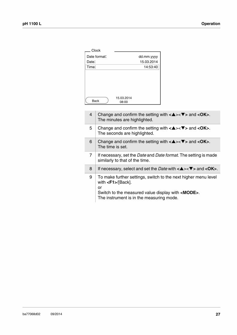
4 Change and confirm the setting with <><> and <OK>.The minutes are highlighted.
5 Change and confirm the setting with <><> and <OK>.The seconds are highlighted.
6 Change and confirm the setting with <><> and <OK>.The time is set.
7 If necessary, set the Date and Date format. The setting is made similarly to that of the time.
8 If necessary, select and set the Date with <><> and <OK>.
9 To make further settings, switch to the next higher menu level with <F1>/[Back].orSwitch to the measured value display with <MODE>. The instrument is in the measuring mode.
Date format: dd.mm.yyyy
Date: 15.03.2014Time: 14:53:40
Clock
15.03.201408:00Back
27ba77068d02 09/2014

Operation pH 1100 L
5.3 Sensor-independent settings
The Storage & config menu comprises the following settings:
System (see section 5.3.1).
Data storage (see section 5.3.2)
5.3.1 System
Overview The following sensor-independent meter characteristics can be adjusted in the Storage & config/System menu:
Menu language
Beep on keystroke
Illumination
Display contrast
Interval of the automatic switch-off function
Data interface
Clock and date function
Reset of all sensor-independent system settings to the default con-dition
Settings To open the Storage & config menu, press the <F1_>/[Menu] key in the measured value display. After completing the settings, switch to the measured value display with <MODE>.
Menu item Setting Explanation
System / General / Language
DeutschEnglish(more)
Selects the menu lan-guage
System / General / Beep
OnOff
Switches on/off the beep on keystroke
System / General / Illu-mination
AutoOnOff
Switches the display illumi-nation on/off
System / General / Contrast
0 ... 100 % Changes the display con-trast
System / General / Switchoff time
10 min ... 24 h Adjusts the switch-off time
System / Interface / Baud rate
1200, 2400, 4800, 9600, 19200
Baud rate of the data inter-face
28 ba77068d02 09/2014

pH 1100 L Operation
5.3.2 Data storage
This menu contains all functions to display, edit and erase stored mea-sured values and calibration records.
NoteDetailed information on the memory functions of the pH 1100 L is given in section 5.5.
5.3.3 Automatic Stability control
The automatic Stability control (AutoRead) function continuously checks the stability of the measurement signal. The stability has a con-siderable impact on the reproducibility of measured values.
You can activate or switch off the automatic Stability control function (see section 5.4.4).
The measured parameter flashes on the display
as soon as the measured value is outside the stability range
when the automatic Stability control is switched off.
System / Interface / Output format
ASCIICSV
Output format for data transmissionFor details, see section 5.6
System / Interface / Decimal separator
Dot (xx.x)Comma (xx,x)
Decimal separator
System / Interface / Output header
Output of a header for Out-put format: CSV
System / Clock TimeDateDate format
Settings of time and date. For details, see section 5.2.4
System / Service infor-mation
Hardware version and soft-ware version of the meter are displayed.
System / Reset - Resets the system settings to the default values. For details, see section 5.8.2
Menu item Setting Explanation
29ba77068d02 09/2014

Operation pH 1100 L
5.4 pH value / ORP voltage
5.4.1 General information
You can measure the following parameters:
pH value [ ]
ORP [mV]
AttentionWhen a grounded PC is connected, measurements cannot be per-formed in grounded media as incorrect values would result.The USB-A (Device) is not galvanically isolated.
Temperaturemeasurement
For reproducible pH measurements, it is essential to measure the tem-perature of the test sample. You have the following options to measure the temperature:
Automatic measurement of the temperature by the temperature sen-sor (NTC30 or Pt1000) integrated in electrode.
Measurement by an external temperature sensor.
Manual determination and input of the temperature.
The measuring instrument recognizes whether a suitable sensor is connected and automatically switches on the temperature measure-ment.
The display of the temperature indicates the active temperature mea-suring mode:
Preparatory activities Perform the following preparatory activities when you want to measure:
Temperature sensor
Resolution of the temp. display
Mode
yes 0.1 °C Automatic with temperature sensor
- 1 °C Manual
1 Connect a pH or ORP electrode to the meter.The pH measuring window is displayed.
2 If necessary, select the pH or mV display with <MODE>.
3 Adjust the temperature of the solutions and measure the cur-rent temperature if the measurement is made without a temper-ature sensor.
4 Calibrate or check the meter with the electrode.
30 ba77068d02 09/2014

pH 1100 L Operation
5.4.2 Measuring the pH value
Stability control(AutoRead )
The stability control function (AutoRead) continually checks the stability of the measurement signal. The stability has a considerable impact on the reproducibility of measured values.
The measured parameter flashes on the display
as soon as the measured value is outside the stability range
when the automatic Stability control is switched off.
Criteria for a stablemeasured value
The Stability control function checks whether the measured values are stable within the monitored time interval.
The minimum duration until a measured value is assessed as stable is the monitored time interval. The actual duration is mostly longer.
HOLD function
1 Perform the preparatory activities according to section 5.4.1.
2 Immerse the pH electrode in the test sample.
3 Select the pH or mV display with <MODE>.
pH
6.94925.0 °C
15.03.201408:00
Menu USB output
Measured parameter
Time interval Stability during the time interval
pH value 15 seconds Δ : better than 0.01 pH
Temperature 15 seconds Δ : better than 0.5 °C
1 Freeze the measured value with <HOLD>.The [HOLD] status indicator is displayed.The HOLD function is active.
31ba77068d02 09/2014

Operation pH 1100 L
5.4.3 Measuring the ORP
NoteORP electrodes are not calibrated. However, you can check ORP elec-trodes using a test solution.
Stability control(AutoRead )
The stability control function (AutoRead) continually checks the stability of the measurement signal. The stability has a considerable impact on the reproducibility of measured values.
The measured parameter flashes on the display
as soon as the measured value is outside the stability range
when the automatic Stability control is switched off.
Criteria for a stablemeasured value
The Stability control function checks whether the measured values are stable within the monitored time interval.
2 Release the frozen measured value again with <HOLD> or <MODE>.The [HOLD] status display disappears. The display switches back to the previous indication.
1 Perform the preparatory activities according to section 5.4.1.
2 Submerse the ORP electrode in the sample.
3 Select the mV display with <MODE>.
U
157.0 mV24.8 °C
15.03.201408:00Menu USB output
Measured parameter
Time interval Stability during the time interval
ORP 15 seconds Δ : better than 0.3 mV
32 ba77068d02 09/2014

pH 1100 L Operation
The minimum duration until a measured value is assessed as stable is the monitored time interval. The actual duration is mostly longer.
HOLD function
5.4.4 Settings for pH and ORP measurements
Overview The following settings are possible for pH and ORP measurements:
Resolution
Calibration interval
Buffers for calibration
Unit of the temperature
Automatic stability control
Unit for slope
Calibration record (display)
Settings The settings are made in the menu for calibration and measurement settings of the pH/ORP measurement. To open the settings, display the required parameter in the measured value display and press the <F1>/[menu] or <OK> key. After completing the settings, switch to the mea-sured value display with <MODE>.
Temperature 15 seconds Δ : better than 0.5 °C
Measured parameter
Time interval Stability during the time interval
1 Freeze the measured value with <HOLD>.The [HOLD] status indicator is displayed.The HOLD function is active.
2 Release the frozen measured value again with <HOLD> or <MODE>.The [HOLD] status display disappears. The display switches back to the previous indication.
Menu item Possible setting
Explanation
Calibration / Calibra-tion record
- Displays the calibration record of the last calibra-tion.
33ba77068d02 09/2014

Operation pH 1100 L
Calibration / Buffer TECAnyCalNIST/DIN TEC 2...
Buffer sets to be used for pH calibration.More buffers and details, see section 5.4.5.
Calibration / Calibra-tion data storage
- Displays the last calibra-tion records.
Calibration / One point calibration
YesNo
Quick calibration with 1 buffer
Calibration / Serial number (sen-sor)
- Entry of the serial number of the connected sensor. The serial number is out-put in the calibration record.
Change the contents of the highlighted position with <><>.
Go to the next position with <F2>/[].
When the serial number has been completely entered, confirm with <OK>.
Calibration / Calibra-tion interval
1 ... 999 d Calibration interval for the pH electrode (in days).The meter reminds you to calibrate regularly by the flashing sensor symbol in the measuring screen.
Calibration / Unit for slope
mV/pH%
Unit of the slope.The % display refers to the Nernst slope of -59.2 mV/pH (100 x determined slope/Nernst slope).
Man. temperature -25 ... +130 °C Entry of the manually determined temperature. For measurements without temperature sensor only.
Menu item Possible setting
Explanation
34 ba77068d02 09/2014

pH 1100 L Operation
5.4.5 pH calibration
Why calibrate? pH electrodes age. This changes the zero point (asymmetry) and slope of the pH electrode. As a result, an inexact measured value is dis-played. Calibration determines and stores the current values of the zero point and slope of the electrode. Thus, you should calibrate at regular intervals.
When do you have tocalibrate?
After connecting another combination electrode
When the calibration interval has expired
Buffer sets forcalibration
You can use the buffer sets quoted in the table for an automatic calibra-tion. The pH values are valid for the specified temperature values. The temperature dependence of the pH values is taken into consideration during calibration.
Temperature unit °C °F
Temperature unit,degrees Celsius or degrees Fahrenheit.All temperature values are displayed with the selected unit.
Resolution pH 0.0010.010.1
Resolution of the pH dis-play:
Resolution mV 0.11
Resolution of the mV dis-play:
Stability control On / Off Switches on or off the automatic stability control during measurement (see section 5.3.3)
Reset - Resets all sensor settings to the delivery condition (see section 5.8.1).
Menu item Possible setting
Explanation
35ba77068d02 09/2014

Operation pH 1100 L
* Brand names or trade names are trademarks of their respective owners protected by law.
NoteThe buffers are selected in the menu, pH / <F1>/[Menu] / Calibration / Buffer (see page 33).
Calibration points Calibration can be performed using one to five buffer solutions in any order (single-point to five-point calibration). The meter determines the following values and calculates the calibration line as follows:
No. Buffer set * pH values at
1 TECTechnical buffers
2.004.007.0010.00
20 °C
2 AnyCal Any Any
3 NIST/DINDIN buffers according to DIN 19266 and NIST Traceable Buffers
1.6794.0066.8659.18012.454
25 °C
4 TEC 2Technical buffers
2.0004.0107.00010.011
25 °C
5 Merck 1* 4.0007.0009.000
20°C
6 Merck 2 * 1.0006.0008.00013.000
20°C
7 Merck 3 * 4.6606.8809.220
20°C
8 Merck 4 * 2.0004.0007.00010.000
20°C
9 Merck 5 * 4.0107.00010.000
25 °C
36 ba77068d02 09/2014

pH 1100 L Operation
NoteYou can display the slope in the units, mV/pH or % (see page 33).
Stability control The calibration procedure automatically activates the stability control function. The current measurement with stability control can be termi-nated at any time (accepting the current value).
Calibration record The new calibration values are displayed when the calibration is fin-ished.
Display calibration dataand output to interface
You can have the data of the last calibration displayed (see page 46). Subsequently, you can transmit the displayed calibration data to the interface, e.g. to a PC, with the <F2>/[USB output] key.
NoteThe calibration record is automatically transmitted to the interface after calibrating.
Sample record
Determined values Displayed calibration data
1-point Asy Zero point = Asy
Slope = Nernst slope (-59.2 mV/pH at 25 °C)
2-point AsySlp.
Zero point = Asy
Slope = Slp.
3-point to 5-point
AsySlp.
Zero point = Asy
Slope = Slp.
The calibration line is calcu-lated by linear regression.
30.03.2014 15:55pH 1100 LSer. no. 08502113
CALIBRATION pH
AutoCal TECBuffer 1 4.00Buffer 2 7.00Buffer 3 10.00Voltage 1 184.0 mVVoltage 2 3.0 mVVoltage 3 -177.0 mVTemperatur 1 24.0 øCTemperatur 2 24.0 øCTemperatur 3 24.0 øCSlope -60.2 mV/pHAsymmetry 4.0 mVSensor +++
etc...
37ba77068d02 09/2014

Operation pH 1100 L
Calibration evaluation After calibrating, the meter automatically evaluates the calibration.The zero point and slope are evaluated separately. The worse evaluation of both is taken into account. The evaluation appears on the display and in the calibration record.
Preparatory activities Perform the following preparatory activities when you want to calibrate:
5.4.6 Calibration interval
The calibration evaluation is displayed as a sensor symbol.
The sensor symbol flashes after the adjusted calibration interval has expired. It is still possible to measure.
Display Calibration record
Zero point [mV]
Slope [mV/pH]
+++ -15 ... +15 -60,5 ... -58
++ -20 ... +20 -58 ... -57
+ -25 ... +25 -61 ... -60.5 or -57 ... -56
- -30 ... +30 -62 ... -61 or -56 ... -50
Clean the electrode according to the electrode operating manual
Error Error < -30 or > 30
... -62 or
... -50
Eliminate the error according to chapter 7 WHAT TO DO IF... (page 62)
1 Connect the pH electrode to the meter.The pH measuring window is displayed.
2 Keep the buffer solutions ready. Adjust the temperature of the buffer solutions, or measure the current temperature, if you measure without a temperature sensor.
38 ba77068d02 09/2014
pH 1100 L Operation
NoteTo ensure the high measuring accuracy of the measuring system, cal-ibrate after the calibration interval has expired.
Setting the calibrationinterval
The calibration interval is set to 7 days (d7) in the factory. You can change the interval (1 ... 999 days):
5.4.7 Carrying out automatic calibration (AutoCal)
Make sure that in the sensor menu, Buffer menu, the buffer set is cor-rectly selected (see page 33).
Use any one to five buffer solutions of the selected buffer set in ascend-ing or descending order.
Below, calibration with Technical buffers (TEC) is described. When other buffer sets are used, other nominal buffer values are displayed. Apart from that, the procedure is identical.
NoteIf single-point calibration was set in the menu, the calibration procedure is automatically finished with the measurement of buffer solution 1 and the calibration record is displayed.
1 Open the menu for measurement settings with <F1>/[Menu].
2 In the Calibration / Calibration interval menu, set the calibration interval with <><>.
3 Confirm the setting with <OK>.
4 Quit the menu with <MODE>.
1 In the measured value display, select the measured parameter pH or mV with <MODE>.
2 Start the calibration with <CAL>.The calibration display for the first buffer appears (voltage dis-play).
39ba77068d02 09/2014

Operation pH 1100 L
NoteFor single-point calibration, the instrument uses the Nernst slope (-59.2 mV/pH at 25 °C) and determines the zero point of the electrode.
Continuing with two-point calibration
3 Thoroughly rinse the electrode with deionized water.
4 Immerse the electrode in buffer solution 1.
5 When measuring without temperature sensor:Measure the temperature of the buffer manually and enter it with <><>.
6 Start the measurement with <OK>.The measured value is checked for stability (stability control). The [AR] status indicator is displayed. The measured parame-ter flashes.
7 Wait for the end of the measurement with stability control or accept the calibration value with <OK>.
8 If necessary, finish the calibration procedure as a single-point calibration with <MODE>.The calibration record is displayed.
pH 1
-180.024.8 °C
AutoCal TEC
15.03.201408:00
Buffer
mV
pH
-180.024.8 °C
AutoCal TEC
10.000
15.03.201408:00
AR
Buffer
mV
9 Thoroughly rinse the electrode with deionized water.
40 ba77068d02 09/2014

pH 1100 L Operation
Continuing with three-to five-point calibration
10 Immerse the electrode in buffer solution 2.
11 When measuring without temperature sensor:Measure the temperature of the buffer manually and enter it with <><>.
12 Start the measurement with <OK>.The measured value is checked for stability (stability control). The [AR] status indicator is displayed. The measured parame-ter flashes.
13 Wait for the measurement with stability control to be completed or terminate the stability control and take over the calibration value with <OK>. The calibration display for the next buffer appears (voltage dis-play).
14 If necessary, finish the calibration procedure as a two-point cal-ibration with <MODE>.The calibration record is displayed.
pH
0.024.8 °C
AutoCal TEC
7.000
15.03.201408:00
AR
Buffer
mV
15 Thoroughly rinse the electrode with deionized water.
16 Immerse the electrode in the next buffer solution.
17 When measuring without temperature sensor:Measure the temperature of the buffer manually and enter it with <><>.
18 Start the measurement with <OK>.The measured value is checked for stability (stability control). The [AR] status indicator is displayed. The measured parame-ter flashes.
41ba77068d02 09/2014

Operation pH 1100 L
NoteCalibration is automatically completed after the last buffer of a buffer set has been measured. Then the calibration record is displayed.
The calibration line is determined by linear regression.
5.4.8 Carrying out a manual calibration (AnyCal)
Make sure that in the sensor menu, Buffer menu, the AnyCal buffer set is correctly selected (see page 33).
Use any one to five buffer solutions in ascending or descending order.
NoteIf single-point calibration was set in the menu, the calibration procedure is automatically finished with the measurement of buffer solution 1 and the calibration record is displayed.
19 Wait for the measurement with stability control to be completed or terminate the stability control and take over the calibration value with <OK>. The calibration display for the next buffer appears (voltage dis-play).
20 If necessary, use <MODE> to finish calibration or switch to calibration with the next buffer with <OK>.
1 In the measured value display, select the measured parameter pH or mV with <MODE>.
2 Start the calibration with <CAL>.The calibration display appears.
pH
180.024.8 °C
AutoCal TEC
4.000
15.03.201408:00
AR
Buffer
mV
42 ba77068d02 09/2014

pH 1100 L Operation
3 Thoroughly rinse the electrode with deionized water.
4 Immerse the electrode in buffer solution 1.
5 When measuring without temperature sensor:Measure the temperature of the buffer manually and enter it with <><>.
6 Start the measurement with <OK>.The measured value is checked for stability (stability control). The [AR] status indicator is displayed. The measured parame-ter flashes.
7 Wait for the end of the measurement with stability control or accept the calibration value with <OK>.
pH
0.024.8 °C
AnyCal
1
15.03.201408:00
Buffer
mV
pH
0.024.8 °C
AnyCal
7.000
15.03.201408:00
Buffer
mV
AR
pH
7.00024.8 °C
AnyCal
1
15.03.201408:00
Buffer
43ba77068d02 09/2014

Operation pH 1100 L
NoteFor single-point calibration, the instrument uses the Nernst slope (-59.2 mV/pH at 25 °C) and determines the zero point of the electrode.
Continuing with two-point calibration
8 Set the nominal buffer value for the measured temperature with <><>.
9 Accept the calibration value with <OK>. The calibration display for the next buffer appears (voltage dis-play).
10 If necessary, finish the calibration procedure as a single-point calibration with <MODE>.The calibration record is displayed.
11 Thoroughly rinse the electrode with deionized water.
12 Immerse the electrode in buffer solution 2.
13 When measuring without temperature sensor:Measure the temperature of the buffer manually and enter it with <><>.
14 Start the measurement with <OK>.The measured value is checked for stability (stability control). The [AR] status indicator is displayed. The measured parame-ter flashes.
15 Wait for the measurement with stability control to be completed or terminate the stability control and take over the calibration value with <OK>.
16 Set the nominal buffer value for the measured temperature with <><>.
pH
4.03524.8 °C
AnyCal
2
15.03.201408:00
Buffer
44 ba77068d02 09/2014

pH 1100 L Operation
Continuing with three-to five-point calibration
NoteAfter the fifth buffer has been measured the calibration is automatically finished. Then the calibration record is displayed.
17 Accept the calibration value with <OK>. The calibration display for the next buffer appears (voltage dis-play).
18 Finish the calibration procedure as a two-point calibration with <MODE>.The calibration record is displayed.
19 Thoroughly rinse the electrode with deionized water.
20 Immerse the electrode in the next buffer solution.
21 When measuring without temperature sensor:Measure the temperature of the buffer manually and enter it with <><>.
22 Start the measurement with <OK>.The measured value is checked for stability (stability control). The [AR] status indicator is displayed. The measured parame-ter flashes.
23 Wait for the measurement with stability control to be completed or terminate the stability control and take over the calibration value with <OK>.
24 Set the nominal buffer value for the measured temperature with <><>.
25 Accept the calibration value with <OK>. The calibration display for the next buffer appears (voltage dis-play).
26 Use <MODE> to finish calibration or switch to calibration with the next buffer with <OK>.
pH
9.95824.8 °C
AnyCal
3
15.03.201408:00
Buffer
45ba77068d02 09/2014
Operation pH 1100 L
The calibration line is determined by linear regression.
5.4.9 Displaying calibration records
The calibration data can be displayed and then output to the interface
Displaying thecalibration record
The calibration record of the last calibration is to be found under the menu item, Calibration / Calibration record. To open it in the measured value display, press the <CAL_> key.
The calibration records of the last calibration procedures are available in the <F1>/[Menu] / Calibration / Calibration data storage and <F1_>/[Menu] / Storage & config/Data storage / Calibration data storage menu.
Menu item Setting/function
Explanation
Calibration / Calibration data stor-age / Display
or
Data storage / Calibration data stor-age / Display
- Displays the calibration record.
Further options: Scroll through the calibration
records with <><>.
Output the displayed calibra-tion record to the interface with <F2>/[USB output].
Quit the display with <F1>/[Back] or <OK>.
Switch directly to the mea-sured value display with <MODE>.
Calibration / Calibration data stor-age / Output to USBor
Data storage / Calibration data stor-age / Output to USB
- Outputs the calibration records to the interface.
46 ba77068d02 09/2014

pH 1100 L Operation
Example
5.5 Data memory
You can transmit measured values (datasets) to the data memory:
Manual storage (see section 5.5.1)
Automatic storage at intervals (see section 5.5.2)
Each data storage process transmits the current dataset to the inter-face at the same time.
Measurement dataset A complete dataset consists of:
ID number
Date/time
Measured value of the connected sensor
Measured temperature value of the connected sensor or manually set temperature
AutoRead info: AR appears with the measured value if the AutoRead criterion was met while storing (stable measured value). Otherwise, the AR display is missing.
Calibration evaluation: +++, ++, +, -, or no evaluation
Storage locations The pH 1100 L meter has two measurement data memories. The mea-sured values recorded either manually or automatic are stored sepa-rately in individual measurement data memories.
30.03.2014 15:55pH 1100 LSer. no. 08502113
CALIBRATION pH
AutoCal TECBuffer 1 4.00Buffer 2 7.00Buffer 3 10.00Voltage 1 184.0 mVVoltage 2 3.0 mVVoltage 3 -177.0 mVTemperatur 1 24.0 øCTemperatur 2 24.0 øCTemperatur 3 24.0 øCSlope -60.2 mV/pHAsymmetry 4.0 mVSensor +++
etc...
47ba77068d02 09/2014

Operation pH 1100 L
5.5.1 Manual storage
You can store a measurement dataset to the data memory as follows. The dataset is at the same time output to the interface:
If the memory is full The following window appears if all 200 storage locations are occupied:
You have the following options:
To erase the entire storage, confirm Yes.
Data memory Maximum number of datasets
Manual data storage 200
Automatic data storage 5000
1 Press the <STR> key shortly.The menu for manual data storage appears.
2 If necessary, change and confirm the ID number (1 ... 10000) with <><> and <OK>.The dataset is stored. The meter switches to the measured value display.
15.03.2014 11:24:16pH 7.000 24.8 °C AR +++
ID number: 1
Continue
Manual data storage 4 From 200
15.03.201408:00
Back
Data storage full. Erase?
YesNo
Warning
15.03.201408:00
Back
48 ba77068d02 09/2014

pH 1100 L Operation
To cancel the storage process and switch to the measured value display, confirm No. Then you can e.g. store the data from the mem-ory to a PC (see section 5.5.3) and subsequently erase the memory (see section 5.5.4).
5.5.2 Automatic storage at intervals
The storage interval (Interval) determines the time interval between automatic data storage processes. Each data storage process trans-mits the current dataset to the interface at the same time.
Configuring theautomatic storage
function
Settings You can configure the automatic data storage function with the follow-ing settings:
1 Press the <STR_> key.The menu for automatic data storage appears.
Adjusted entire storage duration
Max. available storage duration
Graphical display of the memory usage
ID number 1Interval 30 s
Duration 180 min
Continue 0d03h00min
0 1d17h33min
Automatic data storage
15.03.201408:00
Back
Menu item Possible setting Explanation
ID number 1 ... 10000 ID number for the dataset series.
Interval 1 s, 5 s, 10 s, 30 s, 1 min, 5 min, 10 min, 15 min, 30 min, 60 min
Storage interval.
The lower limit of the stor-age interval can be restricted by the number of free storage locations.The upper limit is restricted by the storage duration.
49ba77068d02 09/2014

Operation pH 1100 L
Starting the automaticstorage function
To start the automatic storage function, select Continue with <><> and confirm with <OK>. The meter switches to the measured value dis-play.
The active automatic data storage function can be recognized by the progress bar in the status line. The progress bar indicates the remain-ing storage duration.
NoteIf the automatic storage function is activated, only the following keys are active: Softkeys, <MODE>, <STR_> and <On/Off>. The other keys and the automatic switch-off function are deactivated.
Energy saving mode([Eco mode])
If the automatic storing function is active, the meter provides an energy saving mode ([Eco mode]) to avoid unnecessary energy consumption. The energy saving mode switches off functions of the meter that are not required for the automatic storage of measurement data (such as the display). By pressing any key the energy saving mode is switched off again.
Duration 1 min ... x min Storing duration.Specifies after which time the automatic data storage should be terminated.
The lower limit of the stor-age duration is restricted by the storage interval.The upper limit is restricted by the number of free stor-age locations.
Menu item Possible setting Explanation
pH
6.94925.0 °C
0d03h00min
15.03.201408:00
Remaining storage duration
Graphical display of the storage duration
Eco mode
50 ba77068d02 09/2014
pH 1100 L Operation
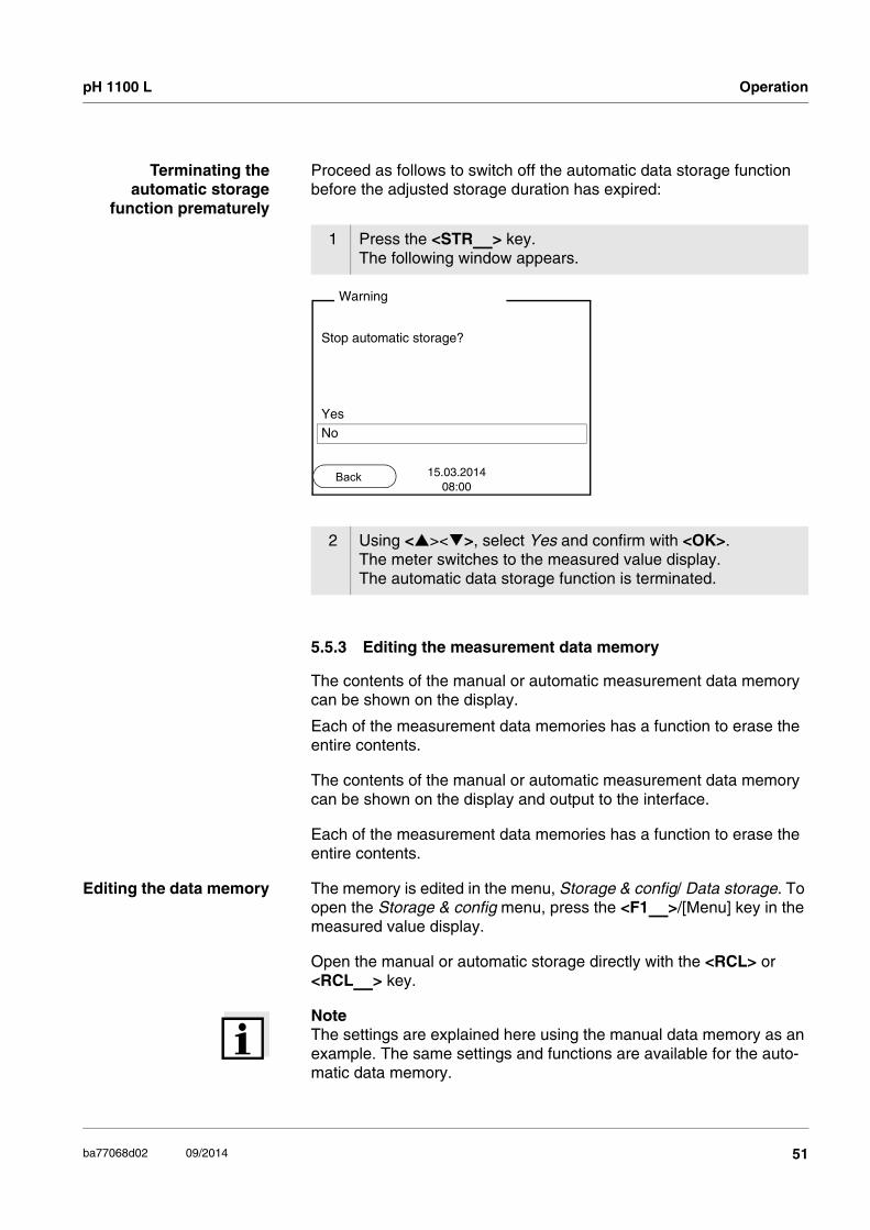
Terminating theautomatic storage
function prematurely
Proceed as follows to switch off the automatic data storage function before the adjusted storage duration has expired:
5.5.3 Editing the measurement data memory
The contents of the manual or automatic measurement data memory can be shown on the display.
Each of the measurement data memories has a function to erase the entire contents.
The contents of the manual or automatic measurement data memory can be shown on the display and output to the interface.
Each of the measurement data memories has a function to erase the entire contents.
Editing the data memory The memory is edited in the menu, Storage & config/ Data storage. To open the Storage & config menu, press the <F1_>/[Menu] key in the measured value display.
Open the manual or automatic storage directly with the <RCL> or <RCL_> key.
NoteThe settings are explained here using the manual data memory as an example. The same settings and functions are available for the auto-matic data memory.
1 Press the <STR_> key.The following window appears.
2 Using <><>, select Yes and confirm with <OK>.The meter switches to the measured value display.The automatic data storage function is terminated.
Stop automatic storage?
Yes
No
Warning
15.03.201408:00
Back
51ba77068d02 09/2014

Operation pH 1100 L
Settings
Display presentation ofa dataset
Menu item Setting/function
Explanation
Data storage / Manual data storage / Display
- Displays all measurement datasets page by page.
Further options: Scroll through the datas-
ets with <><>.
Output the displayed data-set to the interface with <F2>/[USB output].
Quit the display with <F1>/[Back].
Data storage / Manual data storage / Erase
- Erases the entire manual measurement data memory.
Note:All calibration data remain stored when this action is performed.
Data storage / Manual data storage / Output to USB
- Outputs all stored measure-ment data to the interface.
Manual data storage 3 of 64
15.03.2014 11:24:16 ID number: 1
pH 7.000 24.8 °C AR +++
15.03.201408:00
Back USB output
52 ba77068d02 09/2014

pH 1100 L Operation
Example
Quitting the display To quit the display of stored measurement datasets, you have the fol-lowing options:
Switch directly to the measured value display with <MODE>.
Quit the display and move to the next higher menu level with <F1>/[Back].
5.5.4 Erasing the measurement data memory
How to erase the measurement data memory is described in section 5.5.3 EDITING THE MEASUREMENT DATA MEMORY.
30.03.2014 09:56:20pH 1100 L Ser. no. 08502113
ID number 2pH 6.012 24.8 °C, AR, +++________________________________________
30.03.2014 10:56:20pH 1100 L Ser. no. 08502113
ID number 2pH 6.012 24.8 °C, AR, +++________________________________________
53ba77068d02 09/2014

Operation pH 1100 L
5.6 Transmitting data (USB interface)
5.6.1 Options for data transmission
Via the USB interface you can transmit data to a PC. The following table shows which data are transmitted to the interface in which way:
NoteThe following rule applies: With the exception of the menus, shortly pressing the <F2>/[USB output] key generally outputs the display con-tents to the interface (displayed measured values, measurement data-sets, calibration records).
Data Control Operation / descriptionCurrentmeasured values of all connected sensors
Manual With <F2>/[USB output].
Simultaneously with every manual storage process (see section 5.5.1).
Automatic, at intervals
With <F2_>/[USB output]. Then you can set the trans-mission interval.
Note:For operation with MultiLab pilot: set the Send ID option to No (see section 5.7).
Simultaneously with every automatic storage process (see section 5.5.2).
Stored measured values
Manual Displayed dataset with <F2>/[USB output] after calling up from the memory.
All datasets with the Output to USB function.
For details, see section 5.5.3.Calibration records
Manual Calibration record with <F2>/[USB output].
For details, see section 5.6.Automatic At the end of a calibration
procedure.
54 ba77068d02 09/2014

pH 1100 L Operation
5.6.2 Connecting a PC
Connect the pH 1100 L to the PC via the USB interface.
AttentionThe USB interface is not galvanically isolated. When a grounded PC is connected, measurements cannot be per-formed in grounded media as incorrect values would result.
Installation of the USBdriver on the PC
System requirements of the PC for installation of the USB driver:
PC with USB port and CD-ROM drive
Microsoft Windows (for details, see enclosed installation CD, Driver directory)
5.7 MultiLab Importer
With the aid of the MultiLab Importer software, you can record and eval-uate measurement data with a PC.
1 Insert the supplied installation CD in the CD drive of your PC.
2 Install the driver from the CD.Follow the Windows installation instructions as necessary.
3 Connect the pH 1100 L to the PC via the USB interface.The meter is listed as a virtual COM interface among the con-nections in the Windows instrument manager.
More detailed information can be found in the MultiLab Importer operating manual.
55ba77068d02 09/2014

Operation pH 1100 L
5.8 Reset
You can reset (initialize) all sensor settings and sensor-independent settings separately from each other.
5.8.1 Resetting the measurement settings
NoteThe calibration data are reset to the default settings together with the measuring parameters. Recalibrate after performing a reset.
pH The following settings for pH measurements are reset to the default settings with the Reset function:
The sensor settings are reset under the Reset menu item in the menu for calibration and measurement settings. To open the settings, display the required parameter in the measured value display and press the <F1>/[Menu] or <OK> key.
Setting Default settings
Buffer TEC
Cal. interval 7 d
Unit for slope mV/pH
Measured parameter pH
Resolution pH 0.001
Resolution mV 0.1
Asymmetry 0 mV
Slope -59.2 mV
Man. temperature 25 °C
One point calibration Off
Stability control On
Temperature unit °C
56 ba77068d02 09/2014

pH 1100 L Operation
5.8.2 Resetting the system settings
The following system settings can be reset to the default status:
The system settings are reset in the menu, Storage & config / System / Reset. To open the Storage & config menu, press the <F1_>/[Menu] key in the measured value display.
Setting Default settings
Language English
Beep On
Baud rate 4800 Baud
Output format ASCII
Contrast 50 %
Illumination Auto
Switchoff time 1 h
57ba77068d02 09/2014

Maintenance, cleaning, disposal, accessories pH 1100 L
6 Maintenance, cleaning, disposal, accessories
6.1 Maintenance
The only maintenance activity required is replacing the batteries.
NoteSee the relevant operating manuals of the electrodes for instructions on maintenance.
6.1.1 Replacing the batteries
CautionMake sure that the poles of the batteries are positioned correctly.The ± signs on the batteries must correspond to the ± signs in the battery compartment.
NoteAlternatively, you can also use Ni-MH rechargeable batteries (type Mignon AA). In order to charge the batteries, an external charging device is required.
1 Open the battery compartment (1) on the underside of the meter.
2 Remove the batteries from the battery compartment.
1
58 ba77068d02 09/2014

pH 1100 L Maintenance, cleaning, disposal, accessories
6.2 Cleaning
Occasionally wipe the outside of the measuring instrument with a damp, lint-free cloth. Disinfect the housing with isopropanol as required.
CautionThe housing is made of synthetic material (ABS). Thus, avoid con-tact with acetone or similar detergents that contain solvents. Re-move any splashes immediately.
6.3 Packing
This meter is sent out in a protective transport packing. We recommend: Keep the packing material. The original packing pro-tects the meter against damage during transport.
6.4 Disposal
This equipment is marked with the crossed out wheeled bin symbol to indicate that this equipment must not be disposed of with unsorted waste.
Instead it's your responsibility to correctly dispose of your equipment at lifecycle -end by handling it over to an authorized facility for separate collection and recycling. It's also your responsibility to decontaminate the equipment in case of biological, chemical and/or radiological con-tamination, so as to protect from health hazards the persons involved in the disposal and recycling of the equipment.
For more information about where you can drop off your waste of equip-ment, please contact your local dealer from whom you originally pur-chased this equipment.
By doing so, you will help to conserve natural and environmental resources and you will ensure that your equipment is recycled in a man-ner that protects human health.
Thank you
3 Place four batteries (type Mignon AA) in the battery compart-ment.
4 Close the battery compartment.
59ba77068d02 09/2014
Maintenance, cleaning, disposal, accessories pH 1100 L
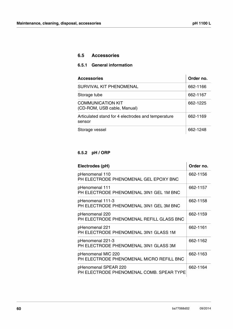
6.5 Accessories
6.5.1 General information
6.5.2 pH / ORP
Accessories Order no.
SURVIVAL KIT PHENOMENAL 662-1166
Storage tube 662-1167
COMMUNICATION KIT(CD-ROM, USB cable, Manual)
662-1225
Articulated stand for 4 electrodes and temperature sensor
662-1169
Storage vessel 662-1248
Electrodes (pH) Order no.
pHenomenal 110PH ELECTRODE PHENOMENAL GEL EPOXY BNC
662-1156
pHenomenal 111PH ELECTRODE PHENOMENAL 3IN1 GEL 1M BNC
662-1157
pHenomenal 111-3PH ELECTRODE PHENOMENAL 3IN1 GEL 3M BNC
662-1158
pHenomenal 220PH ELECTRODE PHENOMENAL REFILL GLASS BNC
662-1159
pHenomenal 221PH ELECTRODE PHENOMENAL 3IN1 GLASS 1M
662-1161
pHenomenal 221-3PH ELECTRODE PHENOMENAL 3IN1 GLASS 3M
662-1162
pHenomenal MIC 220PH ELECTRODE PHENOMENAL MICRO REFILL BNC
662-1163
pHenomenal SPEAR 220PH ELECTRODE PHENOMENAL COMB. SPEAR TYPE
662-1164
60 ba77068d02 09/2014

pH 1100 L Maintenance, cleaning, disposal, accessories
Electrodes (ORP) Order no.
pHenomenal ORP 220REDOX ELECTRODE PHENOMENAL KOMB. 1M BNC
662-1165
Solutions Order no.
Buffer pH 4 AVS TITRINORM, 100 ml 32095.184
Buffer pH 7 AVS TITRINORM, 100 ml 32096.187
Buffer pH 10 AVS TITRINORM, 100 ml 32040.185
Buffer NIST pH 4.01, 30 x 30 ml 1.99001.0001
Buffer NIST pH 7, 30 x 30 ml 1.99002.0001
Buffer NIST pH 10, 30 x 30 ml 1.99004.0001
Storage Solution (3 moles/l KCl), 100 ml 83605.180
Cleaning Solution Pepsine/Hydrochloric acid, 100 ml 83603.180
61ba77068d02 09/2014

What to do if... pH 1100 L
7 What to do if...
Error messageOFL, UFL
Error message,Error
Cause Remedy
pH electrode:
– Measured value outside the measuring range
– Use suitable electrode
– Air bubble in front of the junc-tion
– Remove air bubble
– Air in the junction – Extract air or moisten junc-tion
– Cable broken – Replace the electrode
– Gel electrolyte dried out – Replace the electrode
Cause Remedy
pH electrode:
– The values determined for zero point and slope of the electrode are outside the allowed limits.
– Recalibrate
– Junction contaminated – Clean the junction
– Electrode broken – Replace the electrode
Buffer solutions:
– Incorrect buffer solutions – Change calibration proce-dure
– Buffer solutions too old – Use only once.Note the shelf life
– Buffer solutions depleted – Change solutions
62 ba77068d02 09/2014

pH 1100 L What to do if...
No stable measuredvalue
Sensor symbol flashes
Display
Cause Remedy
pH electrode:
– Junction contaminated – Clean the junction
– Membrane contaminated – Clean membrane
Test sample:
– pH value not stable – Measure with air excluded if necessary
– Temperature not stable – Adjust temperature if nec-essary
Electrode + test sample:
– Conductivity too low – Use suitable electrode
– Temperature too high – Use suitable electrode
– Organic liquids – Use suitable electrode
Cause Remedy
– Calibration interval expired – Recalibrate the measuring system
Cause Remedy
– Batteries almost empty – Replace the batteries (see section 6.1 MAINTENANCE)
63ba77068d02 09/2014

What to do if... pH 1100 L
Obviously incorrectmeasured values
Meter does not react tokeystroke
You want to know whichsoftware
version is in the meter
Cause Remedy
pH electrode:
– pH electrode unsuitable – Use suitable electrode
– Temperature difference between buffer and test sam-ple too great
– Adjust temperature of buf-fer or sample solutions
– Measurement procedure not suitable
– Follow special procedure
Cause Remedy
– Operating condition unde-fined or EMC load unallowed
– Processor reset:Press the <OK> and <On/Off> key simultaneously
Cause Remedy
– E.g., a question by the ser-vice department
– Switch on the meter.Open the menu, <F1_> / [Menu] / Storage & config / SystemService informa-tion. The instrument data are displayed.
64 ba77068d02 09/2014
pH 1100 L Firmware update
65ba77068e02 09/2014
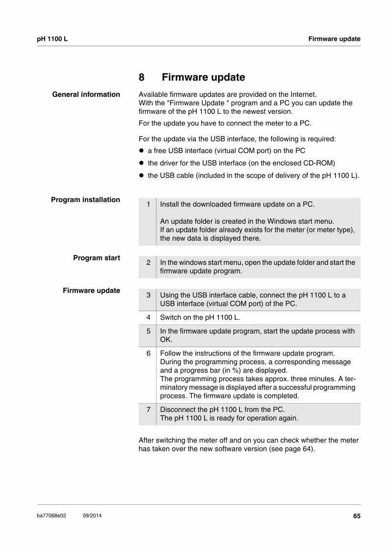
8 Firmware update
General information Available firmware updates are provided on the Internet.With the "Firmware Update " program and a PC you can update the firmware of the pH 1100 L to the newest version.
For the update you have to connect the meter to a PC.
For the update via the USB interface, the following is required:
a free USB interface (virtual COM port) on the PC
the driver for the USB interface (on the enclosed CD-ROM)
the USB cable (included in the scope of delivery of the pH 1100 L).
Program installation
Program start
Firmware update
After switching the meter off and on you can check whether the meter has taken over the new software version (see page 64).
1 Install the downloaded firmware update on a PC.
An update folder is created in the Windows start menu. If an update folder already exists for the meter (or meter type), the new data is displayed there.
2 In the windows start menu, open the update folder and start the firmware update program.
3 Using the USB interface cable, connect the pH 1100 L to a USB interface (virtual COM port) of the PC.
4 Switch on the pH 1100 L.
5 In the firmware update program, start the update process with OK.
6 Follow the instructions of the firmware update program.During the programming process, a corresponding message and a progress bar (in %) are displayed. The programming process takes approx. three minutes. A ter-minatory message is displayed after a successful programming process. The firmware update is completed.
7 Disconnect the pH 1100 L from the PC. The pH 1100 L is ready for operation again.

Lists pH 1100 L
9 Lists
This chapter provides additional information and orientation aids.
Specialist terms The glossary briefly explains the meaning of the specialist terms. How-ever, terms that should already be familiar to the target group are not described here.
Index The index will help you to find the topics that you are looking for.
Glossary
Adjusting To manipulate a measuring system so that the relevant value (e.g. the displayed value) differs as little as possible from the correct value or a value that is regarded as correct, or that the difference remains with-in the tolerance.
Asymmetry see zero point
AutoRange Name of the automatic selection of the measuring range.
Calibration Comparing the value from a measuring system (e.g. the displayed val-ue) to the correct value or a value that is regarded as correct. Often, this expression is also used when the measuring system is adjusted at the same time (see adjusting).
Electromotive force ofan electrode
The electromotive force U of the combination electrode is the measur-able electromotive force of an electrode in a solution. It equals the sum of all the galvanic voltages of the combination electrode. Its de-pendency on the pH results in the electrode function, which is charac-terized by the parameters, slope and zero point.
JunctionThe junction is a porous body in the housing wall of reference elec-trodes or electrolyte bridges. It arranges the electrical contact be-tween two solutions and makes the electrolyte exchange more difficult. The expression, junction, is also used for ground or junction-less transitions.
Measured parameter The measured parameter is the physical dimension determined by measuring, e.g. pH, conductivity or D.O. concentration.
Measured value The measured value is the special value of a measured parameter to be determined. It is given as a combination of the numerical value and unit (e. g. 3 m; 0.5 s; 5.2 A; 373.15 K).
66 ba77068d02 09/2014

pH 1100 L Lists
ORP The ORP is caused by oxidizing or reducing substances dissolved in water if these substances become effective on an electrode surface (e.g. a gold or platinum surface).
pH value The pH value is a measure of the acidic or basic effect of an aqueous solution. It corresponds to the negative decadic logarithm of the molal hydrogen ions activity divided by the unit of the molality. The practical pH value is the value of a pH measurement.
Potentiometry Name of a measuring technique. The signal (depending on the mea-sured parameter) of the electrode is the electrical potential. The elec-trical current remains constant.
Reset Restoring the original condition of all settings of a measuring system.
Resolution Smallest difference between two measured values that can be dis-played by a meter.
Slope The slope of a linear calibration function.
Stability control(AutoRead )
Function to control the measured value stability.
Standard solution The standard solution is a solution where the measured value is known by definition. It is used to calibrate a measuring system.
Test sample Designation of the test sample ready to be measured. Normally, a test sample is made by processing the original sample. The test sample and original sample are identical if the test sample was not processed.
Zero point The zero point of a pH combination electrode is the pH value at which the electromotive force of the pH combination electrode at a specified temperature is zero. Normally, this is at 25 °C.
67ba77068d02 09/2014

Lists pH 1100 L
68 ba77068d02 09/2014

pH 1100 L Lists
Index
AAuthorized use . . . . . . . . . . . . . . . . . . . . . . . 7Automatic switch-off function . . . . . . . . . . . 20AutoRead
pH . . . . . . . . . . . . . . . . . . . . . . 31, 32, 33
BBattery compartment . . . . . . . . . . . . . . 17, 58
CCalibration
pH . . . . . . . . . . . . . . . . . . . . . . . . . . . . 35Calibration evaluation
pH . . . . . . . . . . . . . . . . . . . . . . . . . . . . 38Calibration interval . . . . . . . . . . . . . . . . . . . 38Calibration points
pH . . . . . . . . . . . . . . . . . . . . . . . . . . . . 36Calibration records . . . . . . . . . . . . . . . . . . . 46Connect the power pack . . . . . . . . . . . . . . 17Connecting a PC . . . . . . . . . . . . . . . . . . . . 55
Connectors . . . . . . . . . . . . . . . . . . . . . . 12
DDataset . . . . . . . . . . . . . . . . . . . . . . . . . . . . 47Date and time . . . . . . . . . . . . . . . . . . . . . . . 26Default settings
Measured parameter . . . . . . . . . . . . . . 56System settings . . . . . . . . . . . . . . . . . . 57
Display . . . . . . . . . . . . . . . . . . . . . . . . . . . . 11
EEnergy saving feature . . . . . . . . . . . . . . . . 18Energy saving mode . . . . . . . . . . . . . . . . . 50
FFirmware update . . . . . . . . . . . . . . . . . . . . 65
IInitial commissioning . . . . . . . . . . . . . . 16, 18Initialize . . . . . . . . . . . . . . . . . . . . . . . . . . . 56Interval for calibration . . . . . . . . . . . . . . . . . 38
KKeys . . . . . . . . . . . . . . . . . . . . . . . . . . . . . . 10
MMeasured value display . . . . . . . . . . . . . . . 22Measurement accuracy . . . . . . . . . . . . . . . 39Measurement data memory
Edit . . . . . . . . . . . . . . . . . . . . . . . . . . . . 51Erase . . . . . . . . . . . . . . . . . . . . . . . . . . 51Storage locations . . . . . . . . . . . . . . . . . 47
Measurement dataset . . . . . . . . . . . . . . . . 47Measuring
ORP . . . . . . . . . . . . . . . . . . . . . . . . . . . 32pH . . . . . . . . . . . . . . . . . . . . . . . . . . . . 31
Menu for calibration and measurement settingspH/ORP . . . . . . . . . . . . . . . . . . . . . . . . 33
Menus (navigation) . . . . . . . . . . . . . . . . . . 22Messages . . . . . . . . . . . . . . . . . . . . . . . . . 23
OOperational safety . . . . . . . . . . . . . . . . . . . . 7
PpH buffer sets . . . . . . . . . . . . . . . . . . . . . . 35Precautions . . . . . . . . . . . . . . . . . . . . . . . . . 6Print . . . . . . . . . . . . . . . . . . . . . . . . . . . . . . 54
RReset . . . . . . . . . . . . . . . . . . . . . . . . . . . . . 56
SSafety . . . . . . . . . . . . . . . . . . . . . . . . . . . . . . 6Scope of delivery . . . . . . . . . . . . . . . . . . . . 16Setting the date . . . . . . . . . . . . . . . . . . . . . 18Setting the time . . . . . . . . . . . . . . . . . . . . . 18Single-point calibration
pH . . . . . . . . . . . . . . . . . . . . . . . . . 40, 44Slope
pH . . . . . . . . . . . . . . . . . . . . . . . . . . . . 35Stability control
Automatic . . . . . . . . . . . . . . . . . . . . . . . 29Storage interval . . . . . . . . . . . . . . . . . . . . . 49Storing in memory . . . . . . . . . . . . . . . . . . . 47
Automatic . . . . . . . . . . . . . . . . . . . . . . . 49
69ba77068e02 09/2014

Lists pH 1100 L
Manual . . . . . . . . . . . . . . . . . . . . . . . . 48
TTemperature measurement
pH . . . . . . . . . . . . . . . . . . . . . . . . . . . . 30Three-point calibration
pH . . . . . . . . . . . . . . . . . . . . . . . . . 41, 45Transmitting data . . . . . . . . . . . . . . . . . . . 54Transmitting measured values . . . . . . . . . 54Two-point calibration
pH . . . . . . . . . . . . . . . . . . . . . . . . . 40, 44
ZZero point of pH electrode . . . . . . . . . . . . . 35
70 ba77068e02 09/2014
pH 1100 L Technical service
10 Technical service
Web resources
Visit the VWR website at www.vwr.com for:
Complete technical service contact information
Access to VWR’s Online Catalogue, and information about accesso-ries and related products
Additional product information and special offers
Contact us: For information or technical assistance contact your local VWR representative or visitwww.vwr.com.
11 Warranty
VWR International warrants that this product will be free from defects in material and workmanship for a period of three (3) years from date of delivery. If a defect is present, VWR will, at its option and cost, repair, replace, or refund the purchase price of this product to the customer, provided it is returned during the warranty period. This warranty does not apply if the product has been damaged by accident, abuse, misuse, or misapplication, or from ordinary wear and tear. If the required main-tenance and inspection services are not performed according to the manuals and any local regulations, such warranty turns invalid, except to the extent, the defect of the product is not due to such non-perfor-mance.
Items being returned must be insured by the customer against possible damage or loss. This warranty shall be limited to the aforementioned remedies. IT IS EXPRESSLY AGREED THAT THIS WARRANTY WILL BE IN LIEU OF ALL WARRANTIES OF FITNESS AND IN LIEU OF THE WARRANTY OF MERCHANTABILITY.
12 Compliance with local laws and regula-tions
The customer is responsible for applying for and obtaining the neces-sary regulatory approvals or other authorizations necessary to run or use the Product in its local environment. VWR will not be held liable for any related omission or for not obtaining the required approval or authorization, unless any refusal is due to a defect of the product.
71ba77068e02 09/2014

Compliance with local laws and regulations pH 1100 L
72 ba77068e02 09/2014


Austria
VWR International GmbHGraumanngasse 71150 ViennaTel.: +43 1 97 002 0Fax: +43 1 97 002 600E-mail: [email protected]
Belgium
VWR International bvbaResearchpark Haasrode 2020Geldenaaksebaan 4643001 LeuvenTel.: 016 385 011Fax: 016 385 385E-mail: [email protected]
Czech Republic
VWR International s. r. o.Veetee Business ParkPražská 442CZ - 281 67 Stříbrná SkaliceTel.: +420 321 570 321Fax: +420 321 570 320E-mail: [email protected]
Denmark
VWR - Bie & BerntsenTransformervej 82730 HerlevTel.: 43 86 87 88Fax: 43 86 87 90E-mail: [email protected]
Finland
VWR International OyValimotie 900380 HelsinkiTel.: 09 80 45 51Fax: 09 80 45 52 00E-mail: [email protected]
France
VWR International S.A.S.Le Périgares – Bâtiment B201, rue Carnot94126 Fontenay-sous-Bois cedexTel.: 0 825 02 30 30 (0,15 € TTC/min)
Fax: 0 825 02 30 35 (0,15 € TTC/min)
E-mail: [email protected]
Germany
VWR International GmbHHilpertstraße 20aD - 64295 DarmstadtFreecall: 0800 702 00 07Fax: 0180 570 22 22*Email: [email protected]*0,14 €/Min. aus d. dt. Festnetz
Hungary
VWR International Kft.Simon László u. 4.4034 DebrecenTel.: (52) 521-130Fax: (52) 470-069E-mail: [email protected]
Ireland / Northern Ireland
VWR International Ltd /VWR International (Northern Ireland) LtdOrion Business CampusNorthwest Business ParkBallycoolinDublin 15Tel.: 01 88 22 222Fax: 01 88 22 333E-mail: [email protected]
Italy
VWR International PBI S.r.l.Via San Giusto 8520153 Milano (MI)Tel.: 02-3320311/02-487791Fax: 800 152999/02-40090010E-mail: [email protected]
The Netherlands
VWR International B.V.Postbus 81981005 AD AmsterdamTel.: 020 4808 400Fax: 020 4808 480E-mail: [email protected]
Norway
VWR International ASHaavard Martinsens vei 300978 OsloTel.: 02290Fax: 815 00 940E-mail: [email protected]
Poland
VWR International Sp. z o.o.Limbowa 580-175 GdanskTel.: 058 32 38 200 do 204Fax. 058 32 38 205E-mail: [email protected]
Portugal
VWR International -Material de Laboratório, LdaEdifício NeoparkAv. Tomás Ribeiro, 43- 3 D2790-221 CarnaxideTel.: 21 3600 770Fax: 21 3600 798/9E-mail: [email protected]
Spain
VWR International Eurolab S.L.C/ Tecnología 5-17A-7 Llinars Park08450 - Llinars del VallèsBarcelonaTel.: 902 222 897Fax: 902 430 657E-mail: [email protected]
Sweden
VWR International ABFagerstagatan 18a163 94 StockholmTel.: 08 621 34 00Fax: 08 621 34 66E-mail: [email protected]
Switzerland
VWR International GmbHLerzenstrasse 16/188953 DietikonTel.: 044 745 13 13Fax: 044 745 13 10E-mail: [email protected]
TurkeyPro Lab Laboratuar Teknolojileri Ltd.Şti.a VWR International CompanyOrta Mah. Cemal Gürsel CaddesiÖrdekcioglu Işmerkezi No.32/134896 Pendik - IstanbulTel.: +90216 598 2900Fax: +90216 598 2907Email: [email protected]
UK
VWR International LtdCustomer Service CentreHunter Boulevard - Magna ParkLutterworthLeicestershireLE17 4XNTel.: 0800 22 33 44Fax: 01455 55 85 86E-mail: [email protected]
Australia
VWR International, Pty Ltd.Unit 1/31 Archimedes PlaceMurarrie, Queensland 4172Tel.: 1300 727 696Fax: 1300 135 123
China
VWR International China Co., LtdRm.219, 2100 Dongming RoadPudong New DistrictShanghai 200123Tel.:+86-21-5898 6888Fax:+86-21-5855 8801E-mail: [email protected]
India
VWR Lab Products Private Limited135/12, Brigade Towers, 2nd FloorFront wing, Brigade Road,Bengaluru, India – 560 025Tel.: +91-80-41117125/26 (Bengaluru)Tel.: +91-2522-647911/922 (Mumbai)Fax: +91-80-41117120E-mail: [email protected]
New Zealand
Global Science - A VWR Company241 Bush RoadAlbany 0632, AucklandTel.: 0800 734 100Fax: 0800 999 002E-mail: [email protected]
Singapore
VWR Singapore Pte Ltd18 Gul DriveSingapore 629468Tel.: +65 6505 0760Fax: +65 6264 3780E-mail: [email protected]