ph circuit 5 - atlas scientific one character ascii commands. the ph circuit provides scientific ......
TRANSCRIPT

pH Circuit
AtlasScientificBiology • Technology
Hardware V5.0Firmware V5.0
Features• Full range pH reading from .01 to 14.00• Accuracy within two significant figures (XX.XX)• Single reading or continuous reading modes• Temperature dependent or independent readings• Simple calibration protocol• Simple asynchronous serial connectivity (voltage swing 0-VCC)• Simple asynchronous serial connectivity with 8 different baud rates• Automatic baud rate detection• Simple instruction set consisting of only 14 commands• Debugging LED's• 3.3V to 5.5V operational voltage• Low power consumption• ROHS compliant
2 mA at 3.3V in active mode*1.89 mA at 3.3V in quiescent mode**LED's off
DescriptionThe pH Circuit is a highly compact pH monitoring system that fits into any breadboard. This design configuration allows the user to accurately monitor pH without having to add any additional circuitry or components to your design. Communication with the pH Circuit is done using only 14 simple one character ASCII commands. The pH Circuit provides scientific grade readings to any embedded system that has an asynchronous serial connection interface (voltage swing 0-VCC, not +/- 12 volts).
1Atlas-Scientific.com Copyright © Atlas Scientific LLC All Rights Reserved
as of 4/23/13DISCONTINUED

AtlasScientificBiology • Technology
ContentsSystem Overview .................................................................. Pin Out ................................................................................. Absolute Maximum Ratings .................................................. Device operation .................................................................. L1 ......................................................................................... L0 ......................................................................................... R ........................................................................................... C ........................................................................................... TT.TT ..................................................................................... E ........................................................................................... X ........................................................................................... I ............................................................................................ S ...........................................................................................F ........................................................................................... T ...........................................................................................# ...........................................................................................Z0 ........................................................................................Z(1-8) ...................................................................................Calibration instructions ....................................................... Wiring ................................................................................. Footprint ............................................................................Known issues ......................................................................Warranty .............................................................................
3345666777888899
10101112131414
2Atlas-Scientific.com Copyright © Atlas Scientific LLC All Rights Reserved

AtlasScientificBiology • Technology
Atlas-Scientific.com 3
System OverviewStandard pH circuitry can be bulky and complex, often operating at voltages outside of the typical logic level realm. Atlas Scientific has reinvented the way pH monitoring is done. The pH Circuit is an embedded solution designed to output quick, calibration free, scientific grade pH readings in a simple asynchronous serial data transmission. From a single “as needed” pH reading to an infinite number of readings, the pH Circuit will deliver an accurate reading in just 378 milliseconds.
It is important to keep in mind that only temperature dependent readings can be considered scientific grade pH readings. Without adding temperature information to your reading request the pH Circuit will use a default temperature of 25 C°. See page 7 for more information.
Pin Out
RX
Return for the DC power supply. GND (& Vcc)must be ripple and noise free for best operation.
GND
Vcc Operates on 3.3V – 5.5V
TX output delivers asynchronous serial data in a TTL RS-232 format, except voltagesare 0-Vcc. The output is (up to twelve) ASCII characters representing the pHor status messages; all ending with a carriage return (ASCII 13).
Example
4.60<CR>
The default baud rate is: 38400, 8 bits, no parity, with one stop bit.The voltage swing 0-VCC, not +/- 12 voltsIf standard voltage level RS232 is desired, connect an RS232 converter such as a MAX232.
TX
TTL RS-232 receive pin
PRB pH Sensor connection*For best results use an Atlas Scientific pH Sensor
Copyright © Atlas Scientific LLC All Rights Reserved

Atlas-Scientific.com 4
AtlasScientificBiology • Technology
Absolute Maximum Ratings*
Power Consumption
Parameter MIN TYP MAX Units
Storage temperature(pH Circuit)
-40 125 C°
1 3525
3.3
C°
3.3 5.5 V
Storage temperature(pH probe)
VCC
Parameter 5V 3.3V
LED on (Active) 14 mA 4 mA
2.3 mA 2 mA
7.6 mA 3.6 mA
1.89 mA2 mA
LED off (Active)
LED on (Quiescent)
LED off (Quiescent)
*Note: Stresses above those listed under “Absolute Maximum Ratings” may cause permanent damage to the device. Exposure to maximum rating conditions for extended periods may affect device reliability
Copyright © Atlas Scientific LLC All Rights Reserved

AtlasScientificBiology • Technology
Atlas-Scientific.com 5
Device operation
Command list Quick reference
When the pH Circuit is connected to a power supply (3.3v to 5.5v) the green “Active Mode” indicator LED will begin blinking with transmission. The device will immediately enter continuous mode and begintransmitting pH data.
There are a total of 14 different commands that can be given to the pH Circuit.All commands must be followed by a carriage return <CR>.Commands are not case sensitive.
Command Function Default state
L1 Enables debugging LEDs Enabled
L0 Disables debugging LEDs Disabled
R Takes one pH reading N/A
C Takes continuous pH readings every 378 Milliseconds. N/A
E Stops all readings. Enter standby/quiescent mode. N/A
S Calibration at pH Seven N/A
F Calibration at pH Four N/A
T Calibration at pH Ten N/A
X Return Circuit to factory settings N/A
I Information: Type of Circuit • firmware version • firmware creation date N/A
# (xxxx, !, ?) Set Device ID No ID Set
TT.TT Take temperature dependent reading. 25 C°
Copyright © Atlas Scientific LLC All Rights Reserved
Z0 Change baud rate 38,400 bps
Z(1-8) Set fixed baud rate Z6 (38,400 bps)

AtlasScientificBiology • Technology
Atlas-Scientific.com 6
Command DefinitionsL1 This will enable both debugging LED's.
The pH Circuit has two LED'sGreen LED ..............................Data TXRed LED ..................................Unknown instruction received
By default, the LED's are enabled.These LED's are designed to help the user determine that the pH Circuit is operating properly.
Changes to this setting are written to EEPROM memoryand therefore will be retained even if the power is cut.
Full proper syntax: l1<cr> or L1<CR>
L0 This will disable both debugging LED's.
Changes to this setting are written to EEPROM memory and thereforewill be retained even if the power is cut.
Full proper syntax: l0<cr> or L0<CR>
R Instructs the pH Circuit to return a single pH reading.
*This instruction takes 378 milliseconds to complete
Full proper syntax: r<cr> or R<CR>
The pH Circuit will respond: XX.XX<CR>
If the pH Circuit reads a pH that is out of range (i.e. a pH of 76.2)The pH Circuit will respond with the error message “check probe”
check probe <CR>
Copyright © Atlas Scientific LLC All Rights Reserved

AtlasScientificBiology • Technology
Atlas-Scientific.com 7
C The pH-Circuit will operate in continuous mode and deliver a pH reading every 378 milliseconds until the “e” command is transmitted.
Full proper syntax: c<cr> or C<CR>
The pH Circuit will respond: pH.pH ( where pH.pH represents a pH reading)
Delivering the “E” (END) instruction when not in continuous modewill have no effect on the pH Circuit.
The pH Circuit will respond by ceasing data transmission.There is no ASCII response to this instruction.
pH.pH<CR> (378 milliseconds)pH.pH<CR> (756 milliseconds)pH.pH<CR> (1134 milliseconds)pH.pH<CR> (n+ 378 milliseconds)
If pH Circuit detects that a pH sensor is not connected or damaged it will not transmit a pH reading.Instead it will respond with the error message “check probe”
check probe <CR>
Temperature data will be lost if Circuit is powered off. When the pH Circuitis powered on again temperature will go back to its default of 25°C
tt.tt (where “t” is temperature in °C) By transmitting a temperature to the pH Circuit a temperature compensated pH reading will be returned. The temperature entered will now be the new default temperature. Therefore it is not necessary to transmit a temperature each time a reading is taken.
Full proper syntax: 35<CR> or 35.67<CR>
Full proper syntax: e<CR> or E<CR>
E This instructs the pH Circuit to end continuous mode and enter its standby/quiescent mode.
Copyright © Atlas Scientific LLC All Rights Reserved

AtlasScientificBiology • Technology
Atlas-Scientific.com 8
X Instructs the pH Circuit to return to its original factory settings.
Transmitting this command will:
Reset calibration off set back to 0.Reset default temperature back to 25°CSet debugging LED to on.
Full proper syntax: x<cr> or X<CR>
The pH Circuit will respond: reset<CR>
I Instructs the pH Circuit to transmit it version number.
A comma separated string will be transmitted that will contain 3 values.1. The type of device: 2. The firmware version number: 3. The firmware version date:
Full proper syntax: i<cr> or I<CR>
The pH Circuit will respond: P,V5.0,5/13<CR>
“P” (for pH)“V5.0”“5/13” (May / 2013)
S This instructs the pH Circuit to calibrate itself to a pH7 solution.
Full proper syntax: s<CR> or S<CR>
The pH Circuit will respond with a calibrated pH reading:
7.00<CR>
Sending the S command when the pH sensor is not immersed in a pH 7 solutionwill calibrate the pH Circuit to see that whatever it was reading to now be a pH 7and could lead to significant errors. Do not do this.
F This instructs the pH Circuit to calibrate itself to a pH4 solution.
Full proper syntax: f<CR> or F<CR>
The pH Circuit will respond with a calibrated pH reading:
4.00<CR>
Sending the S command when the pH sensor is not immersed in a pH 4 solutionwill calibrate the pH Circuit to see that whatever it was reading to now be a pH 4and could lead to significant errors. Do not do this.
Copyright © Atlas Scientific LLC All Rights Reserved

AtlasScientificBiology • Technology
Atlas-Scientific.com 9
T This instructs the pH Circuit to calibrate itself to a pH10 solution.
Full proper syntax: t<CR> or T<CR>
The pH Circuit will respond with a calibrated pH reading:
10.00<CR>
Sending the S command when the pH sensor is not immersed in a pH 10 solutionwill calibrate the pH Circuit to see that whatever it was reading to now be a pH 10and could lead to significant errors. Do not do this.
Copyright © Atlas Scientific LLC All Rights Reserved
Example:
Full proper syntax: #nnnn<cr>
Setting the device ID number to “12AB”#12AB<cr>
The pH Circuit will respond:Set 12AB<cr>
#nnnn
#!
#?
Set 4 digit programmable ID number
Reset ID number
Query ID number
Where nnnn is an ID number consisting of numbers 0-9 and letters A-Z.
Setting the pH Circuit ID number is done by issuing the # commandfollowed by any combination of 4 ASCII letters or numbers.The ID does not come set. A factory reset will NOT clear the ID number.
Full proper syntax#!<cr>
The pH Circuit will respond:clr<cr>
Full proper syntax#?<cr>
The pH Circuit will respond with the ID number that it has been given.nnnn<cr>
If the ID number has not been set the pH Circuit will respondNo ID set<cr>

AtlasScientificBiology • Technology
Atlas-Scientific.com 10Copyright © Atlas Scientific LLC All Rights Reserved
Example
Example
Setting baud rate
Transmitting the “Z0<cr>” command will set the pH Circuit to auto baud detection mode.The red/green LEDs will rapidly blink, the pH Circuit will be waiting to receive the letter “U” (Ascii 85) followed by a <cr> at one of the eight possible baud rates.
(at default baud rate 38.4k bps)Z0<CR> or z0<cr>The pH circuit will now begin rapid red/green LED blinking
Change your TX baud rate to your desired setting - i.e. 9600 baud and send the “U” commandU<CR>
The pH Circuit will now operate at 9600 baud
The Atlas Scientific pH circuit is set to a default rate of 38,400 bps. This baud rare can be changedto one of eight possible different baud rates.
1: 300 baud2: 1200 baud3: 2400 baud4: 9600 baud5: 19.2k baud6: 38.4k baud7: 57.6k baud8: 115.2k baud
Z0 Set the auto baud rate
Z(1-8) Set fixed baud rate
(at default baud rate 38.4k bps)
z4<cr> OR Z4<CR>
The pH Circuit baud rate has now been changed from 38.4k bps to 9600 bpsThe baud rate can be changed at any time, and as many times as you like.
Sending the Z(1-8) command will instantly set the pH Circuit to a new baud rate. This new baud rate will be stored to EEPROM and will be retained even if the pH Circuit is powered off.
* By using the Z0 command the pH circuit will enter baud rate detection mode each time it is powered up. If this is not desired simply use the Z(1-8) command
AtlasScientificBiology • Technology
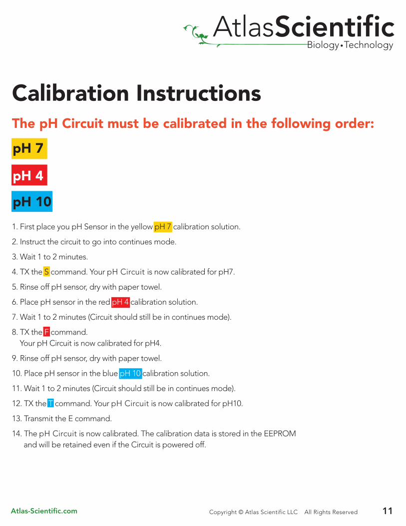
Calibration InstructionsThe pH Circuit must be calibrated in the following order:
1. First place you pH Sensor in the yellow pH 7 calibration solution.
2. Instruct the circuit to go into continues mode.
3. Wait 1 to 2 minutes.
4. TX the S command. Your pH Circuit is now calibrated for pH7.
5. Rinse off pH sensor, dry with paper towel.
6. Place pH sensor in the red pH 4 calibration solution.
7. Wait 1 to 2 minutes (Circuit should still be in continues mode).
8. TX the F command. Your pH Circuit is now calibrated for pH4.
9. Rinse off pH sensor, dry with paper towel.
10. Place pH sensor in the blue pH 10 calibration solution.
11. Wait 1 to 2 minutes (Circuit should still be in continues mode).
12. TX the T command. Your pH Circuit is now calibrated for pH10.
13. Transmit the E command.
14. The pH Circuit is now calibrated. The calibration data is stored in the EEPROM and will be retained even if the Circuit is powered off.
Atlas-Scientific.com 11Copyright © Atlas Scientific LLC All Rights Reserved
pH 7
pH 4
pH 10

AtlasScientificBiology • Technology
Atlas-Scientific.com 12
REMEMBER ALL TRANSMITION ARE TERMANATED WITH A <CR>. THEY ARE NOT TERMANATED WITH A <CR><LF>.MAKE SURE YOUR CODE DOES NOT INADVERTENTLY SEND <CR><LF> AT THE END OF A TRANSMITION.
OK= I<CR> NOT OK = I<CR><LF>
*A pH sensor will typically last between three and four years*A pH sensor should be considered inaccurate if it has been frozen*A pH sensor should be considered inaccurate if it has been allowed to dry*A pH sensor should be considered inaccurate if it has been boiled
*The Wire length from the pH sensor to the pH Circuit should be as short as possible to reduce noise.
Do not use this type of connection
14.00 mm
20.16 mm
Copyright © Atlas Scientific LLC All Rights Reserved
Do not use protoboard
AtlasScientificBiology • Technology
Atlas-Scientific.com 13Copyright © Atlas Scientific LLC All Rights Reserved
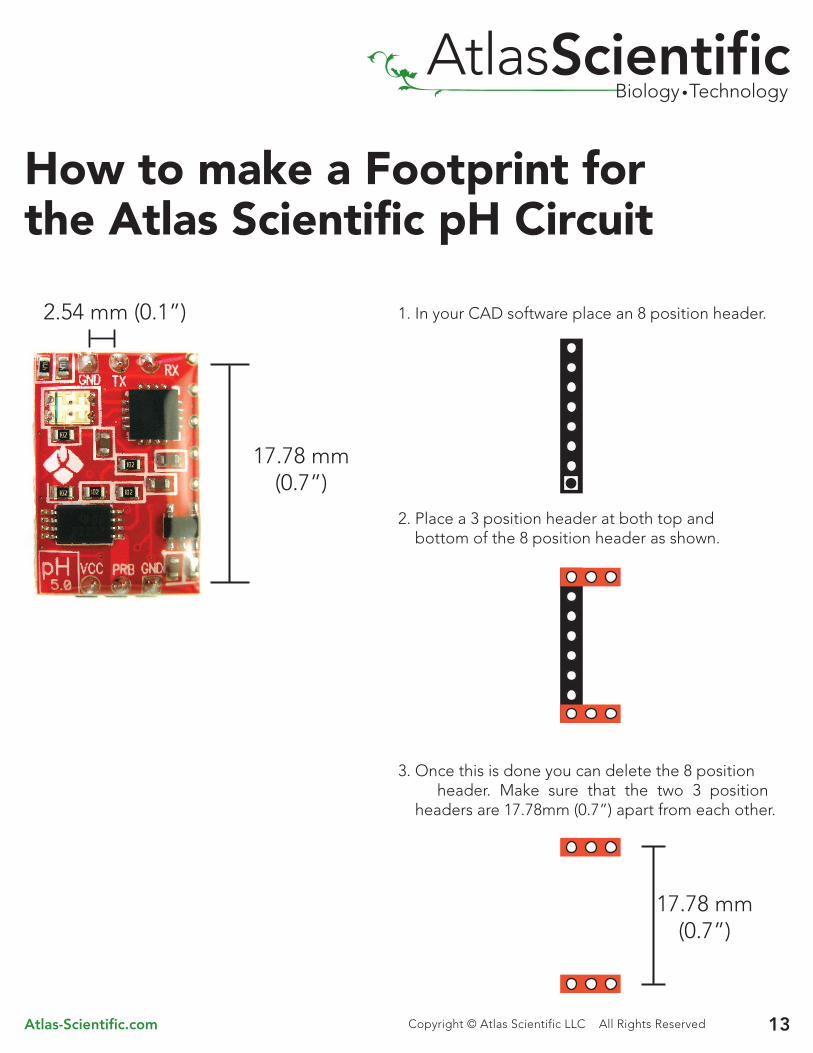
How to make a Footprint forthe Atlas Scientific pH Circuit
1. In your CAD software place an 8 position header.
2. Place a 3 position header at both top and bottom of the 8 position header as shown.
3. Once this is done you can delete the 8 position header. Make sure that the two 3 position headers are 17.78mm (0.7”) apart from each other.
2.54 mm (0.1”)
17.78 mm(0.7”)
17.78 mm(0.7”)

AtlasScientificBiology • Technology
Known IssuesDuring calibration; rapidly switching the pH sensor from a pH 4 to a pH 10 when the pH Circuit is in continues mode can cause a device reset. This will NOT damage the pH Circuit. Simply re-send the “c” command and continue with calibration.
Touching the pH Circuit can cause false readings; these readings can last as long as 5 minutes. As the pH Circuit returns to normal operation the pH readings will progressively return to normal.
Uneven heating can cause the pH Circuit to return false readings. Thermal stability should be considered when using this product.
Atlas-Scientific.com 14Copyright © Atlas Scientific LLC All Rights Reserved
Warranty
The debugging phase
Atlas Scientific warranty’s the pH Circuit to be free of defect during the debugging phase of device implementation, or 30 days after receiving the pH Circuit (which ever comes first).
The debugging phase is defined by Atlas Scientific as the time period when the pH Circuit is inserted into a bread board or shield and is connected to a microcontroller according to this wiring diagram. Reference this wiring diagram for a connection to USB debugging device, or if a shield is being used, when it is connected to its carrier board.
If the pH Circuit is being debugged in a bread board, the bread board must be devoid of other components. If the pH Circuit is being connected to a microcontroller, the microcontroller must be running code that has been designed to drive the pH Circuit exclusively and output the pH Circuit’s data as a serial string.
It is important for the embedded systems engineer to keep in mind that the following activities will void the pH Circuit’s warranty:
• Soldering any part of the pH Circuit• Running any code that does not exclusively drive the pH Circuit and output its data in a serial string• Embedding the pH Circuit into a custom made device • Removing any potting compound

AtlasScientificBiology • Technology
Atlas-Scientific.com 15Copyright © Atlas Scientific LLC All Rights Reserved
Reasoning behind this warranty Because Atlas Scientific does not sell consumer electronics; once the device has been embedded into a custom made system, Atlas Scientific cannot possibly warranty the pH Circuit against the thousands of possible variables that may cause the pH Circuit to no longer function properly.
Please keep this in mind:
*Atlas Scientific is simply stating that once the device is being used in your application, Atlas Scientific can no longer take responsibility for the pH Circuit continued operation. This is because that would be equivalent to Atlas Scientific taking responsibility over the correct operation of your entire device.
1. All Atlas Scientific devices have been designed to be embedded into a custom made system by you, the embedded systems engineer.
2. All Atlas Scientific devices have been designed to run indefinitely without failure in the field. 3. All Atlas Scientific devices can be soldered into place. however you do so at your own risk.
