pg 1934-1951 coolingandheatinginthecementgrindingprocess text
TRANSCRIPT

"Holderbank" Cement Seminar 2000
Process Technology I - Cement Grinding Systems
"HOLDERBANK"
Cooling and Heating in the Cement Grinding Process
Hp. Fisch
PT99/14489/E
1. Introduction 612
2. Cooling and heating possibilities 613
3. Mill ventilation and dedusting 614
3.1 Mill air cooling 614
3.2 Mill heating for blended cements 615
4. Filter technology ....617
5. Water injection 618
6. Cooling in the separator 621
7. Cement coolers 622
8. Heat balance (energy balance) 624
© Holderbank Management & Consulting, 2000 Page 61
1

"Holderbank" Cement Seminar 2000 =Process Technology 1 - Cement Grinding Systems
1. INTRODUCTION
Cooling and heating in the cement grinding process becomes more and more important. Onone hand the market demands in many areas cool cement (e.g. < 60 °C) and on the other
hand the cement manufacturing process requires an accurate balancing of the material
temperature. The grinding process does not only require cooling but also heating is
necessary in many cases to keep the process optimal and to assure a determined cement
quality. Specially with the increasing production of blended cements with moist additives, the
temperature must be neatly monitored and assured to efficiently produce a good quality
product.
The following paper deals with cooling and heating of tube mill systems. Someconsiderations are also valid in an adapted way to other mill principles such as roller
presses, vertical and horizontal roller mills.
What refers to drying and heat balances for various materials is dealt with in the paper
"Drying Technology PT 96/14027/E". The heat balance at the end of this paper is adapted
for a cement grinding system.
Page 612 © Holderbank Management & Consulting, 2000

"Holderbank" Cement Seminar 2000Process Technology I - Cement Grinding Systems
'HOLDERBANK'
2. COOLING AND HEATING POSSIBILITIES
Fig.1 Cooling / heating possibilities
H20 H20
Cooling and HeatingProeasa Technology
There are and were many possibilities for cooling and heating in the cement grinding
process. The main possibilities are:
Cooling
Air cooling of the mill (mill ventilation), where the air has a combined function of cooling
and to some extent material transport through the mill.
Air cooling in the separator by using an adjustable amount of ambient air to cool the mill
discharge product which will be divided into finish product and separator returns.
Water spray into the mill, depending on the conditions into the 1stand/or the 2
nd
compartment, to keep the mill discharge temperature within limits.
Cement cooling with a cement cooler. The cement slides over a water cooled cylindrical
surface and is cooled by convection.
Heating
Hot gases/air can be used to evaporate the moisture in the mill feed and to keep the
temperature profile within the mill above determined levels. Hot gas may be supplied byhot gas generators or kiln exhaust gases as well as clinker cooler exhaust air used.
© Holderbank Management & Consulting, 2000 Page 613
"Hoiderbank" Cement Seminar 2000Process Technology I - Cement Grinding Systems
'HOLDERBANK'
3. MILL VENTILATION AND DEDUSTING
3.1 Mill air cooling
Purpose
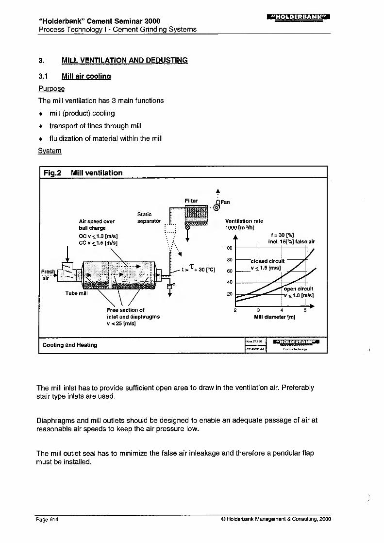
The mill ventilation has 3 main functions
mill (product) cooling
transport of fines through mill
fluidization of material within the mill
System
Fig.2 Mill ventilation
Filter
Air speed over
ball charge
OCv<1.0[m/s]CCv<1.5[m/s]
Static
separator
J Fa"
t «
ta^+sorc]
Free section of
inlet and diaphragms
v«25[m/s]
Ventilation rate
1000 [m 3/h]
f = 30 [%]
incl. 15[%] false air
3 4 5
Mill diameter [m]
Cooling and Heating «^.!J'iU.:ljj;.).!.M;i;.<^
Process Technology
The mill inlet has to provide sufficient open area to draw in the ventilation air. Preferably
stair type inlets are used.
Diaphragms and mill outlets should be designed to enable an adequate passage of air at
reasonable air speeds to keep the air pressure low.
The mill outlet seal has to minimize the false air inleakage and therefore a pendular flap
must be installed.
Page 614 © Hoiderbank Management & Consulting, 2000
"Holderbank" Cement Seminar 2000
Process Technology I - Cement Grinding Systems
"HOLDERBANK'
The static separator is still used in older mill systems. For new installations the static
separator is no more used as the new dynamic separators are more efficient.
Dimensioning of mill ventilation
Air flow rate
The installed air flow rate is only based on the air speed over the ball charge. Fig 2
shows the values based on nominal mill diameters, 30 [%] ball filling and 1 5 [%] false air.
The air flow rates are therefore nominal fan volumes.
Air speeds for system dimensioning are:
• closed circuit mills < 1 .5 [m/s] over ball charge
• open circuit mills < 1 .0 [m/s] over ball charge
Inlet, outlet and diaphragms, maximum air speeds of < 25 [m/s] related to gross open
area.
A false air rate of -15 [%] has to be considered between mill outlet and fan. This results
normally in air temperature of 5 [°C] below cement temperature at mill discharge. Higher
temperature differences point to higher false air rates.
The mill exhaust air temperature must always be kept > 30 [°C] above the dew point
temperature (t) to avoid condensation problems. Excessive false air favors
condensation.
3.2 Mill heating for blended cements
In many cases, specially when grinding blended cements with moist additives, heating is
required instead of cooling.
Up to a certain moisture content in the feed, clinker and grinding heat are sufficient to
evaporate the moisture. However often additional heat is required for drying. This heat can
be taken from kiln exhaust gases, clinker cooler exhaust air or be generated by an auxiliary
furnace (hot gas generator).
As a general rule it can be said, that the material fed to the mill must be dry at the
intermediate diaphragm. If not, severe operating problems may arrive e.g. clogging of
diaphragm, bad material flow behaviour etc.
The experience has shown, that material temperature below -100 [°C] at the intermediate
diaphragm reduces the grinding efficiency and the mill production (due to moist material and
poor material flow). With such conditions, due to grinding heat of the 2ndcompartment, the
mill discharge temperature increases and must be cooled down again by water injection in
the mill outlet to reach the appropriate product temperature at the mill discharge.
© Holderbank Management & Consulting, 2000 Page 61
5

"Holderbank" Cement Seminar 2000
Process Technology I - Cement Grinding Systems
'HOLDERBANK'
Fig.3 Mill heating for blended cements
_^_ Product
Air
Oust ladden air
H2OHot air
Recirculating air Cooling by
water injection
Cooling and Heating "ii-lVHri-Mi'lProcass Tachndogy
In cases of drying needs, all separating air in the separator must be recirculated to keep the
maximum temperature of the separator grits returning to the mill inlet and keep the
maximum heat within the mill system.
For blended cements with lower moisture contents, drying can take place directly in the first
grinding compartment. With higher moisture contents a drying compartment is necessary or
the additives must be dried before feeding to the mill. The limit for drying in the grinding
compartment is approx. 4 [%] mixed moisture in the mill feed, but depending on the clinker
temperature and clinker proportion in the mix, as well as the available hot gas temperature.
The mill inlet temperature with hot gases should not exceed 300 [°C], as above this
temperature adverse effects on gypsum dehydration will take place.
Special attention should be paid to dimensioning of the hot gas generator. Many times hot
gas generators are sized for the maximum drying needs plus reserve. In these cases the
turn down ratio must be such, that also minor moisture contents can correctly be dried with a
good and stable operation of the furnace.
Bag filters for dedusting of the mill system must be insulated and cold spots avoided to
eliminate the risk of condensation.
Page 616 © Holderbank Management & Consulting, 2000
"Holderbank" Cement Seminar 2000Process Technology I - Cement Grinding Systems
"HOLDERBANK"
4. FILTER TECHNOLOGY
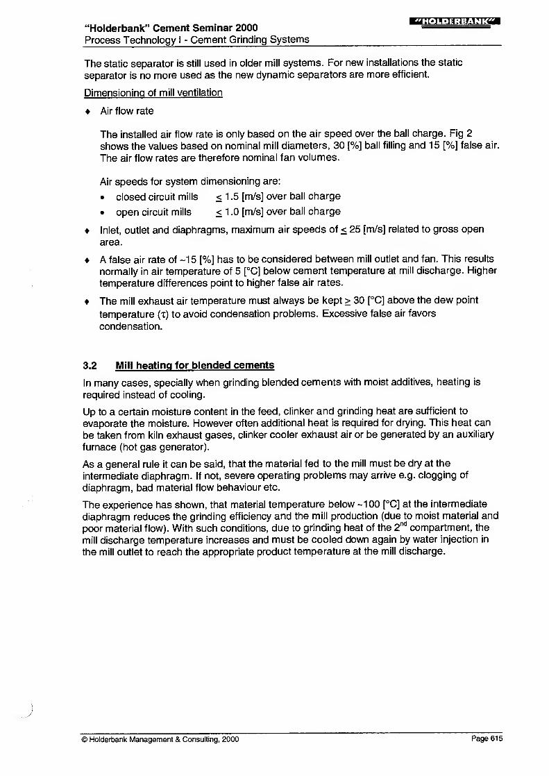
For dedusting of mills and separators only bag filters are used today, regardless of the fact
that ordinary portland or blended cements are produced. Electrostatic precipitators are no
more applied due to operational and environmental reasons.
The mill bag filter should only be used for mill ventilation and not additionally dedust other
equipment. Also mill dedusting air drawn through the dynamic separator must be avoided
due to operational difficulties.
Filter sizing
Fig.4 Filter technology
plenum clean gas
exhaust
raw gas
from mill
drop out boxdust discharge
raw gas dust content 300 - 800 [g/m3]
clean gas dust content < 25 [mg/m3]
Ap filter =5-14[mbar]
Filter sizing
Air cloth ratio
80 [m3/m2 x h] without grinding aid
60 [m3/m2 x h] with grinding aid
Bag dimensions
bag 140-160 [mm]bag lengths <-4.5 [m]
Filter cloth
- needle felt/polyester
- Dolomite
PEAC - mixed needle felt
- new products
(e.g.teflon treated fibres)
Compressed air
i 0.13- 0.19 [m3/hxm2]
- general purpose
>- drying/grinding
applications
Cooling and Heating Hil-iViliWiHIJ*Process Technology
A properly sized and well engineered filter avoids a lot of operating problems and saves
costs.
Filter design
There are many different types, makes and philosophies to design and install bag filters.
Preferred filters are pulse jet types. It is important to install a properly sized filter with
sufficient compressed air. The compressed air must have decent air dryers, specially in
tropic countries to avoid contact of moist air with cement and hence clogging of the bags.
In case of higher dew points and installations outside of buildings an insulation of the filter is
necessary.
A dust drop-out box can be installed at raw gas dust contents > 300 [g/m3], however not all
suppliers favor such installations.
Walk-in plenums present advantages with regard to tight housings (less false air) and can
be installed outdoors without problems.
© Holderbank Management & Consulting, 2000 Page 617

"Holderbank" Cement Seminar 2000Process Technology 1 - Cement Grinding Systems
».».H;i:M?na
Filter operation
Special attention should be paid to the shut down procedure:
Continue cleaning the filter bags for a couple of cleaning cycles before allowing the
temperature to drop below the dew point. As the filter cools, moisture may condense on
the bags once the dew point is reached.
Do not store dust in the hopper. The presence of any moisture will cause it to set,
requiring manual work for its removal.
Allow bags to clean down after dust has stopped entering the hopper, but do not over
clean.
Check to see that all components are in the proper shut down mode.
5. WATER INJECTION
Purpose
Tube mills generate a lot of heat and together with hot clinker increase the product
/temperature along the mill axis. Too high material temperatures in the mill may cause
coating (hampering fluidization of material)
false set of cement (by dehydration of gypsum to soluble anhydrite and then
recrystallization to gypsum)
cement storage problems in silo (lump formation).
If the cooling by fresh air and radiation/convection is not sufficient, water injection into the
mill is necessary. The aim of water injection is to evaporate water and so to extract heat
from the material.
Water injection systems
Fig.5 Water injection - systems
counter currentProduct
temp. [°C]
Air from
H2O blower
(Double)
Rotary union
no water
injection
•H2O 2nd Comp,
H2O 1st Comp.
counter
current
co-current
Cooling and HeatingPtoc«s Technology
Page 618 © Holderbank Management & Consulting, 2000

"Holderbank" Cement Seminar 2000
Process Technology I - Cement Grinding Systems
!MI.»:iiM?fT
Fig.6 Water injection - devices
Mill InletMill trunnion
detail A detail B
Material feed /
Mill OutletWater
Material discharge
Operating Pressures
min 3
normal 4-6
max 9
Air blower>50
Compressed
air ~5[bar]
Cooling and HeatingKJ
ili
,
l V<:|
i l
:UtLf^Process Technology
Water can be injected into the
1stcompartment
2ndcompartment
• from inlet (co-current)
• from outlet (counter-current)
The co-current injection into the 2ndcompartment requires an installation of the water pipe
from the center of the inlet around the shell of the first compartment to the center of the
intermediate diaphragm. The installation is more complex but the cooling effect is morefavorable, as the temperature increase is slight and the temperature level is lower than for
counter-current installations (graph, of Fig. 5). The injection should be in form of a spray
rather than a jet to keep the evaporation in the first part of the compartment.
Counter-current injections are easy installations (except with central drives) and cool down
rapidly the last part of the compartment. In general, the temperature level over the second
compartment is higher than with co-current injections. The injection should be a jet reaching
far into the grinding compartment.
Counter-current systems are easy to install in mills with pinion or side drives. With central
drives, injection glands around the central drive shaft have to be fitted. Many poor
experiences with the tightness of these glands have been made and therefore it is not
recommended to adopt such solutions.
If ever possible the water spray nozzles should be surrounded by tubes, carrying air from a
blower to keep the nozzle always clean (Fig. 6). Leading compressed air together to the
water pipe and to the spray nozzle is an other solution.
© Holderbank Management & Consulting, 2000 Page 619

"Holderbank" Cement Seminar 2000
Process Technology I - Cement Grinding Systems
Operation
Every time the cement mill is running or the mill ventilation is on, the cleaning air of the
water injection system must be running. After a mill stop, the air cleaning system must
continue for a few minutes.
Water is in general first injected into the second compartment and only when the cement
temperature at the mill discharge exceeds 100 [°C]. Injection into the first compartment is
only allowed when feeding hot clinker (mixed temperature > 100 [°C]). Below these
temperatures there is a risk of not sufficient evaporation of the water and clogging of
diaphragms.
Water injection acts like grinding aid in the mill and fluidizes the material. The control of
water injection should therefore always gradually be changed (no steps) to avoid rapid
emptying or filling of the mill.
When no water is injected the solenoid valves must be closed and tight to avoid water from
dripping into the mill.
In most cases the max. portion of water injected into the first and second compartment is
done according to their percentage in length e.g. max 1/3 into the first and 2/3 into the
second compartment.
Control
Fig.7 Water injection - control
Compressed air Index
Air blower
control
loop
setpoint
fH^N cement^ s temperature/
mill exhaust
temperature
Water tank
(2) Floater valve
(3) Shut-off valve
Filter
(?) Water pump
(?) Contact pressure gauge
(7) Pressure relieve valve
(5) Pressure regulator
(9) Flow control valve
@ Flowmeter
@ Pressure gauge
@ Solenoid valve
@ Injection nozzle
(fi) Shut-off valve
(j5) Pressure regulator
@ Solenoid valve
67) Check valve
Cooling and HeatingKm* 27.1.00
Proem Technology
The water injection is controlled with a control loop in function of the clinker or cement
temperature.
In the first compartment either the clinker temperature of the mill feed or the cement
temperature at the intermediate diaphragm are the process values measured.
In the second compartment either the cement (mill discharge) or the exhaust gas/air
temperature can be taken. The exhaust air temperature is normally min. 5 [°C] below the
cement temperature, depending on the false air rate.
Page 620 © Holderbank Management & Consulting, 2000

"Holderbank" Cement Seminar 2000Process Technology I - Cement Grinding Systems
The control loop consists of a water flow meter which value is compared to the set point of
the controller (based on measured temperature). Any change is transmitted the water flow
control valve for a corresponding adjustment.
COOLING IN THE SEPARATOR
Fig.8 Cooling in the separator
Single-pass separator recirculating air
[m3/h] 85 [°C]
65'000 [m3/h]
fresh air .\> . Tan r°n ^30 [°C]
Mill feed:
95 [%] Clinker 130 [°C]
5 [%] Gypsum 20 [°C]
50 [t/h]
. Product
Air
. Oust ladder! air
85 [°C]
Fan75'800 [m3/h]
80 [°C]
50 [t/h] OPC
95 [°C]
(example)
Cooling and HeatingCC-99036.d$l Procvsa Technology
Cooling of the cement, finish product and separator grits, can be done in the separator, in
case the separator system allows for.
New separators can be fitted with bag filters as single pass separators. The air passes
through the separator, filter and fan. The clean fan exhaust air can be blown to the
atmosphere or recirculated to the separator inlet. Fresh air substitutes the exhausted air and
does the cooling in the separator. The more fresh air with ambient temperature is used the
higher is the cooling effect. The more air is recirculated the lower the cooling.
At least 5 [%] of the total separating air is always fresh air in form of false air inleakage. Thecooling level is adjusted by the recirculating and the fresh air flap.
A cold mill should always be started up with a maximum amount of recirculating air to heat
up the mill system. As soon as the operating temperatures of the mill system are reached
then fresh air can be used to cool down the material to the target temperatures.
A maximum cement cooling capacity of a separator, cooling with fresh air is around 25 - 30
[°C]. For higher cooling needs, additional cooling facilities e.g. cement coolers have to be
used.
Besides cooling the finish cement to the silo, this cooling method also cools down the
separator grits returning to the mill inlet. Cool separator grits have on one hand a cooling
effect in the first mill compartment but can on the other hand cool down too much. At too low
material temperatures at the intermediate mill diaphragm the mill production is reduced. In
this case the temperature level of the separator grits must be increased again by
recirculating more warm separating air back to the separator inlet.
© Holderbank Management & Consulting, 2000 Page 621

"Holderbank" Cement Seminar 2000Process Technology I
- Cement Grinding Systems
!r.».»:i:M?rrai
In any case a detailed heat balance must be calculated to give the necessary information for
the prevailing situation and the cooling/heating needs.
Fig. 8 shows a tube mill system with a singlepass separator. The example shows the cooling
effect at maximum fresh air amount used at the separator inlet. As a result, the material
temperature at the intermediate diaphragm is low and leads to reduced mill production rate.
CEMENT COOLERS
Fig.9 Cement coolers
manhole
Cooling diagram
Temperature [°C]
120
Cement Inlet
Water Outlet
Outlet
Inlet
Cooling and HeatingEC
Proous Technology
Purpose
Cylindrical cement coolers are efficient and low energy consuming solutions to cool downthe cement after the grinding process. Reasons for cooling may be
customer requirement
cement bagging and bag handling at low temperature
avoid lump formation in the cement silos (<70 [°C]: reduction of water release from
gypsum dehydration)
Principle
Water cascades in a thin layer over a cylindrical body from the top to the bottom and cools
down the cooler shell. Hot cement is introduced to a type of screw conveyor at the bottom
and conveyed up along the cooler shell to the discharge at the top. Intense heat transfer
occurs from the cement powder at the inside of the shell, through the shell wall to the water
layer at the outside. The cooling occurs in counter current, that means the best cooling is
done with the lower water temperature at the cement discharge at the top of the cylinder.
The cooling water recirculates in a closed water circuit. A water cooler reduces the water
temperature before feeding it again to the top of the cylinder.
Page 622 © Holderbank Management & Consulting, 2000
"Holderbank" Cement Seminar 2000
Process Technology I - Cement Grinding Systems
'HOLDERBANK'
Performance
Cement coolers exist up to 200 [t/h] for a single cylinder.
The cylinder size varies with the cement throughput and the cooling capacity.
Cooling the cement from 1 20 [°C] down to -60 [°C] is common.
The spec, cooling rate is approx. 1 .25 [kJ/m °C h].
Typically the cooing water is heated up from 25 - 40 [°C] along the cylinder.
Spec, electrical energy consumption of cooler and water treatment plant is approx. 1
[kWh/t] cement.
Increasing ovality of the cylindrical shell decreases the efficiency. A minimum clearance
between screw flights and shell has to be aimed at.
Water treatment
The water must have an acceptable quality, often the water must be softened by
decalcifying units to avoid lime furring on the cooling surfaces.
Lime furring can also be reduced through a cathodic protection of the shell.
The water consumption in a closed water circuit refers only to the make-up water due to
the losses in the water cooling units.
© Holderbank Management & Consulting, 2000 Page 623

"Holder-bank" Cement Seminar 2000
Process Technology I - Cement Grinding Systems
"HOLDERBANK"
HEAT BALANCE (ENERGY BALANCE)
Fig.10 Heat balance - system
Heat Input
Separator
Feed material (sensible heat)
Motors (separ+fan)
Fresh air
X Input
Mill
Grinding heat
Feed materials
Separator tailings
Water (total)
GasesVentilation air
(incl.false air)
X Input
Heat Output
Separator
Cement heat
Tailings heat
Separator exhaust
Radiation / convection
X,Output
exhaust air
Mill
Cement heat
Radiation / convection
Evaporated water
Exhaust air / gas
2 Output
water
injectionradiation
convection
Cooling and HeatingProcess Taerwciogy
If ever cooling or heating needs must be calculated, the appropriate model is a heat balance
calculation. The aim of such a calculation is to check the temperatures at the critical points
and the quantities of cooling air, water or hot gases needed to fulfil the requirements.
In principle all heat inputs (energy) have to be equal to the heat outputs of the system in
question.
Heatbaiance:
X Inputs = X Outputs
Procedure
1
)
Define borders of the system(s); for cement grinding systems it is recommended to
define two systems, separator and mill part.
2) Define inputs and outputs for each system.
3) Compute the balances based on
Heat inputs = outputs
Air/gas flows inputs = outputs
4) Observe the restrictions
- max. gas/air speeds in mill, mill inlet/outlet
- max. gas temperature at mill inlet (available and recommended)
- max. possible water injection rate for 1sland 2
ndcompartment
[kJ/kg product]
[Nm3/h]
Page 624 © Holderbank Management & Consulting, 2000

"Holderbank" Cement Seminar 2000Process Technology I
- Cement Grinding Systems
- plant altitude (density of air)
Hints
The balance can be equally done for any grinding equipment (tube mill, vertical mill,
roller press, horizontal mill etc.) based on the same principle and adapting the systems
according to the features of the equipment.
The heat is always related to 1 [kg] of finish cement at the system outlet.
The heat balance is based on the reference temperature of 20 [°C], therefore the At is
always (t-20) and negative heats are possible.
All grinding heats of the major electrical consumers are referred to their motor shafts
and have to be converted to the mechanical power absorbed of this equipment if
necessary.
The evaporation heat of water consists of heating up the water to the operating
temperature an the subsequent portion of evaporation energy.
The radiation/convection losses are often assumed and are related to an estimated
surface (e.g. mill surface times factor x) at an estimated surface temperature (e.g. t-10
[°C]).
Heat balance example
Fig. 11 Heat Balance Cement Mill Example ajMKid-fcT.rrea
HealBalahie MiB. :
Grinding heat Pa-.," r, ' 3.6 " 1000 10 ' 1000 5000 " 0.91 " 3.6 1000 /(180 " 1000) 91 D [kJ*g] 33.4 i%)
Separator tailings G • (u-1)) "cp "(t-20)" 1000 IG ' 1000 180 ' (2-1)" 0.819 "(104-20) /(160 ' 1000) 68.8 |kj*g] 2SJ2 [%1
Feed m aterial heat O cp * (t-20) / G " 1 000 180" 0.806 " (110-20) /(180 1000) 73 2 |kJ*g] 26.9 [%l
Water (teed + injection) W;„" 4.2* (t-20) 10 « 1000 S410 « 4.2 " (15-20) /(160 " 1000) -0.7 [kJAgl -0.2 [%l
Gases Va • cp (t-20) / G • 1 000 11 •000" 1 .529 • (4S0-20) /(180 1000) 40 2 [kJAcg] 14.8 [%l
Air (including false air) V.. • cp • (t-20) IO " 1000 IS^SO "13" (20-20) /(180 ' 1000) 0.0 [kJ*g] 0.0 [%i
INPUT: 272.5 [kJ/kgl 100 l%l
Cem ent heat ex m iD G u cp " (t-20) " 1 000 10 " 1000 1S0 " 2 " 0.822 " (110-20) /(180 ' 1000) 148.0 |kJ*g) 54.3 t%]
Radiation / convection fc' A " (t-20) " 3.6 10 1000 14.15" 1030 ' (110-20)" 3.6 /(180 " 1000) 26.2 [kJ/kg] 9.6 [%]
W ater (evaporated) W,,' q IG • 1000 5'410 • (2501 + (1.86 105))/(180 1000) 81.1 [kJ*g] 29.8 [%l
Exhaust aw /gas V... " cp * (t-20) IG " 1000 26'850 " 1 358 (105-20) /(180 " 1000) 172 |kj*g] 6.3 [%]
OUTPUT
:
272.5 IkJ/kg] 100 i*i
HeatBalante Separator
Separator Feed G " u " cp" (t-20)" 1000 /G " 1000 180 "2 " 0522 * (110-20) " 1000 /(180 " 1000) 148.0 (kjflcgj 97.0 I*]
Motors separator + fan P „„ " 11 » 3 .6 " 1 000 /G • 1000 282 "0.8 "3.6 /(180-1000) 4.5 |kj*g] 3.0 [%]
Separating air (fresh) Vt'1 .3 " (t-20) / G " 1 000 3'032 " 1.3 "(20-20) /(180 "1000) 0.0 IkJfcg] 0.0 [%]
INPUT: 1S2.5 (hj/kg) 100 1*1
Talings G " (u-1)" cp ' (t-20)" 1000 /G " 1000 180 ' (2-1)* 0.819 " (104-20) / (180 "1000) 68.8 |W*g] 45.1 1%)
Radiation /convection k " A "(t-20)" 3.6 /G " 1000 14.15" 550 * (104-20) "3.6 /(180 ' 1000) 13.1 [W*g] 8.6 I%]
System exhaust air V«„"cp"(t-20) / G " 1 000 3,032" 1.3 " (104-20) /(180 " 1000) 1.8 IkJ/kg] 1.2 [%]
Cem ent heat G " cp " (t-20)" 1000 IG " 1000 180 " 0.819 " (104-20) /(180 " 1000) 68.8 [kjftgj 45.1 I%]
OUTPUT
:
152.5 IkJ/kg) 100 [%]
Heat o federation q = 250 1 + (1 .33 " t) frJ/kg H*0J heal of evaporation 3t exhaust temperature
Radraiion /convection factor k = ((At^-tO) 055) 6.75 (kJ/m'^Ch]
Balance related to : 1 [kg] of cement
Reference temperature 20 |"C]
© Holderbank Management & Consulting, 2000 Page 625

"Holderbank" Cement Seminar 2000
Process Technology I- Cement Grinding Systems
'HOLDERBANK'
Cement grinding system
System:
[%]
Tube mill with separator
Mill diameter
Mill length
Motor power
Overall drive eff.
Operating data:
Production
Composition Clinker
Gypsum
Pozzolana
Clinker temperature
Ambient temperature
Water temperature
Hot gas temperature
Mill inlet temperature
Mill discharge temp, (cement)
Mill discharge temp, (gas)
Finish product temperature
Mill fan flow rate
4.6 [m]
15.5 [m]
5000 [kW] abs.
91 [%]
180 [t/h] Pozzolana cement
71 [%] gypsum
4 [%] 4 [%] H2
25 [%] 8 [%] H2
150 [°C]
20 [°C]
15 [°C]
450 [°C]
-200 [°C]
110 [°C]
105 [°C]
104 [°C]
33000 [Nm3/h]
Index
G [t/h] mill production
u [-] circulation factor (feed/product)
t [°C] Temperature
Pabs. [kW] absorbed power (counter)
Tl [-] efficiency of drives
cp [kJ/kg]
[kJ/Nm3]
spec, heat value (related to reference temperature)
W [l/h] water to be evaporated
index: in moisture in feed material (incl. water injected)
ev evaporated water
V [Nm3/h] air/gas flow rate
index: g gas
a fresh air
ex exhaust air
s fresh air separator
k [kJ/m2°C h] radiation/convection factor
A [m2]
radiation surface
q [kJ/kg H20] heat of evaporation
Page 626 © Holderbank Management & Consulting, 2000
"Holderbank" Cement Seminar 2000
Process Technology I - Cement Grinding Systems
wuiii-»'U:i:tAt\nm
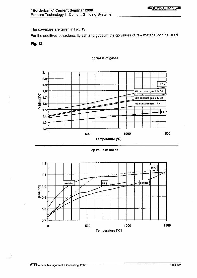
The cp-values are given in Fig. 12.
For the additives pozzolana, fly ash and gypsum the cp-values of raw material can be used.
Fig. 12
cp value of gases
500 1000
Temperature [°C]
1500
cp value of solids
1.2
1.1
5" 1-0o
t-0.9
0.8
0.7
- Si02
2
•
*
~~^7*
,«.---
rawmeal slag ^* clinker
- *
*
/t^
/r
500 1000
Temperature [°C]
1500
© Holderbank Management & Consulting, 2000 Page 627
"Holderbank" Cement Seminar 2000
Process Technology I - Cement Grinding Systems
Page 628 © Holderbank Management & Consulting, 2000