petrobras well technology - brazil oil and...
TRANSCRIPT

Petrobras Well Technology
Brazil oil & gas
Norway oil & gas
Saudi Arabia oil & gas
EPRASHEEDsignature seri�
www.eprasheed.com
Brazil oil & gas
Norway oil & gas
Saudi Arabia oil & gas
Supplement to

Petrobras Well Technology
Accenture
Emerson
Bearing Point
BJ
Weatherford
Impact
Marintek
Halliburton
Perbras
Fugro
Sintef
9
11
15
25
29
39
49
55
61
65
ADVERTISERS
Felipe RegoDrilling Engineering and
Special Operation ManagerPetrobras
Braulio Bastos General Manager of
Well Technology Petrobras
Wajid RasheedCEO & Founder
EPRasheed
Antonio LageWell Technology Manager
CENPES, Petrobras
Joao Carlos PlacidoPetroleum Engineer CENPES, Petrobras
Contributing EditorsAdolfo Polillo Filho, Agostinho Calderon, A. Leibsohn Martins, Alex McKellar, Allen D. Gabrysch, Andrea Sa, Antonio Lage, A.T. Borges, Atila Fernando Lima, C.A.Pedroso, C.J.M. Junior, C.M. Chagas, E.F. Nogueira, Emmanuel Franco, Erdem Catak, Fernando Antônio Medeiros, Gilson Campos, Helder Pinheiro, Helio Santos, Humberto Maia, J.A. Melo, João Carlos Plácido, Joe Kinder, José Eduardo de Lima Garcia, L.C.A. Paixão, L.C.C. Marques, L.H.C. Fernandes, Lirio Quintero, M.O.Martins, N.J. Denadai, Paul Sonnemann, Paulo Barata, Pedro Paulo, Raimundo dos Anjos, R.D. Machado, Renato Pinheiro, Rui Passarelli, Valdo Ferreira Rodrigues, V.P. Barbosa.
CEOWajid [email protected]
Managing EditorMajid [email protected]
66-67
Petrobras Well Technology
Wajid RasheedCEO & Founder
EPRasheed
WELL TECHNOLOGY
200 Horizontal Open-Hole Gravel Packs in the Campos Basin: A Milestone in the History of Petrobras Completion in Ultra-deepwaters
Casing and Liner Drilling in Brazil
First Field Applications of Microflux Control Show Very Positive Results
A Novel Approach for Drilling and Gravel Packing Horizontal Wells in the Presence of Reactive Shales Using a Solid-Free Synthetic Fluid
Torpedo Base - A New Conductor Installation Process
Intelligent Wells in Petrobras
PROPOÇO
Petrobras’ Propoço Looks to Top Quartile Performance
Information Management and Performance Evaluation (INF)
Continuous Process Management and Standardization (PROC)
Project Management, Planning and Control (PROJ)
Knowledge and Workforce Management (CON)
Contents...
4
6
8
12
14
16
26
32
40
50
56

Petrobras’ Propoço Looks to Top Quartile Performance
A ‘roadmap’ for realising top performance, Propoço em-phasizes extensive planning,
best practices and information shar-ing as the way forward. Consequent-ly, it applies ‘thresholds’ or minimal requirements and ‘benchmarks’ or standards for projects, personnel, wells and documents. By propagat-ing best practices it promotes effi -ciency.
By looking at the processes and fl ow of information behind planning, drilling and completing an Oil or Gas well, Propoço will help engineers plan wells from inception to drilling
and completion. Not just by using chronograms but detailed well engi-neering studies including all neces-sary calculations and designs for a specifi c well.
Th e backbone of the program is a comprehensive analysis of Petro-bras well engineering activities and recommendations on areas for im-provement. Propoço is based on four distinct programs with the overall Propoço management plan consid-ered separately.
Th e second program – Information Management and Performance
Evaluation (INF) – seeks to recommend KPI and adopt minimum performance standards. It also seeks to permanently and systematically compare Petrobras well engineering with other oil companies and as a result identify and adopt best practices. It also aims to defi ne a standard well-engineering documentation system.
Th e third program – Continuous Process Management and Standard-ization (PROC) - seeks to review the management of well-engineering processes especially those related to standardization, in order to develop
6 • Petrobras Technology
I n t r o d u c t i o n
Petrobras’ Propoço Looks to Top Quartile Performance
a system that is less bureaucratic and fi t-for-purpose based on critical suc-cess factors and the actual needs of users. It also seeks to review the way ‘lessons learned’ and non-confor-mance are applied.
Based on a simplifi ed operational version of Petrobras’ PRODEP model – Project Management, Planning and Controls (PROJ) -- is the fourth pro-gram within Propoço. PROJ focuses
on implementing a well design and approval system using an integrated management approach. Th e well design and approval system is split into three stages – concept, draft and management plan – combining scope, cost, quality, risk, team, sup-ply/procurement and communica-tion.
Th e fi fth program – Knowledge and Workforce Management (CON) -- is
concerned with attracting, training and retaining technically capable people within well-engineering func-tions. It also identifi es needs for well engineering competency areas as well as allocating technical person-nel where necessary. Additionally, it develops specialists, integrates tech-nical communities as well as creating tools and standards for engineering processes.
Key Performance Indicators
(KPI) are routinely used by Oil
companies to measure oper-
ational performance. In drill-
ing, for example, a common
indicator is a Depth v Days
curve. Using a graph, specific
well construction events are
plotted against the duration
or time taken per event. This
highlights ‘flat-spots’ show-
ing the occurrence of down-
time or NPT (non-productive
time). Worldwide, the average
value for NPT varies between
20-30% of overall well con-
struction time. Oil companies
with the highest performance levels typically exhibit NPT between 10-15%.
Petrobras launched the Propo-
ço program which aims to place the company in the top quartile of well construction performance by improving the well planning process and reducing NPT associated with well construction and mainte-nance.
The potential gains are clear; reduced NPT means more wells completed with fewer rigs. For example, achieving a
reduction of 10% NPT from
an overall NPT of 20% trans-
lates into a net saving of 10% of
rig-time and consequently rig-
cost. When the NPT reduc-
tions are applied across more
rigs the savings soon stack up.
10 or more rigs, the perfor-
mance gains effectively mean
an extra rig, free-of-cost. For
an oil company that has 30 rigs
and manages to reduce NPT
by 10%, this effectively means
3 fewer rigs which lowers de-
mand for rigs while construct-
ing wells more quickly.
Petrobras Technology • 7
Propoço – Petrobras’ program for Excellence in Well-Engineering
8 • Petrobras Technology
P r o p o ç o I N F
Information Management and Performance Evaluation (INF)
The second program – Infor-mation Management and Per-formance Evaluation (INF) –
seeks to recommend KPI and adopt minimum performance standards. It also seeks to permanently and systematically compare Petrobras well engineering performance with other oil companies and as a result identify and adopt best practices. It also aims to define a standard well-engineering documentation system. The INF program is divided into 6 sub-projects which range from the management of sub-projects, diag-nostics, documentation, well-engi-neering KPI, offshore and onshore benchmarking.
INF ManagementThis sub-project covers initial diag-nostics that are used to identify all potential areas of improvement as well as drawing up detailed work-plans for sub-projects. It also covers internal and external communica-tion procedures and content.
Diagnostic Analysis of Current PracticesCo-ordinated by Paulo Barata, this sub-project focuses on analysing cur-
rent well-engineering INF practices as related to information and docu-mentation systems and finding so-lutions that guarantee standardized and integrated practices, databases and applications across all Petrobras well-engineering operations. It in-cludes but is not limited to the struc-tures and ways in which information is collected and documented.
It specifically covers areas such as:
Wellfile, SEP, DIMS, Open wells (structures, licences etc), SAP, Stan-dards and directives (SINPEP), SI-TOP, SIGA, Well Portal, Norms (NORTEC), Instruction Manuals, Technical Reports based on missions or congresses, PRODEP and SIN-DOTEC reports and HP Intranet.
Results of the diagnosis will enable Petrobras well-engineering informa-tion and documentation systems to be restructured in a standard inte-grated format.
Implementation of Information and Documentation SystemsOnce diagnostics have been carried out, information and documenta-
tion systems will be restructured to ensure standardization and integra-tion of practices, databases and ap-plications across the company’s well engineering operations. This sub-project is also coordinated by Paulo Barata and covers the implementa-tion of well-engineering informa-tion and documentation systems co-herent with directives and planning proposed in the earlier diagnostic stage.
Designed specifically to effectively capture all necessary well-engineer-ing information, the new integrated system will store and handle infor-mation and documents in a standard format.
Well Engineering KPI Coordinated by Joao Carlos Ribeiro Placido, this sub-project assesses pro-cess performance indicators used in well-engineering. The program seeks to redefine both final and interim KPI across all well-engineering pro-cesses ensuring minimal standards or ‘threshold’ are met. It also includes input, result indicators and a thresh-old, which covers cost, timeline and conformance with specifications and
Petrobras Technology • 9
P r o p o ç o I N F
model to accompany corrective and other actions within each process. External benchmarking includes a contract with companies for bench-marking analysis.
The Onshore benchmarking system covers all well-engineering processes related to land rigs and modules. It is based on similar processes to those of Offshore benchmarking in terms of internal and external benchmark-ing, with the only difference being that the nature of the information collected is from Onshore assets. Again, the system allows for perfor-mance comparisons between differ-ent assets, identifying improvement actions and best practices managed by Petrobras ENGP.
quality standards. The program will result in a number of standardized Petrobras KPI for well-engineering across all assets.
Offshore and Onshore BenchmarkingBy establishing two separate well-engineering performance evaluation processes for Offshore and Onshore assets respectively, Petrobras will be able to ‘benchmark’ process perfor-mance through a series of audits. This will clearly identify and prior-itise areas of improvement enabling best practices to be subsequently implemented across all offshore and onshore assets.
Coordinated by Renato Pinheiro, the Offshore Benchmarking project encompasses all Well Engineering processes in floating rigs and fixed platforms. The project distinguishes between internal and external bench-marks. For internal benchmarks, procedures are drawn up for the in-formation that needs to be captured. This information is used to form the basis of a benchmark that is imple-mented in all well-engineering assets managed by each business unit. In order to compare performance be-tween different assets, the system will check, rank and identify improve-ments and best practices managed by Petrobras ENGP. The system also incorporates a planning and control
10 • Petrobras Technology
P r o p o ç o P R O C
Continuous Process Management and Standardization (PROC)
Coordinated by Helder Pinheiro, the third Propo-ço program – Continuous
Process Management and Standard-ization (PROC) - will review the management of current well-engi-neering processes, especially those related to standardization. It is struc-tured in 5 sub-projects and will be based on the actual needs of users as well as critical tasks and will deliver a less bureaucratic and fit-for-purpose system. By reviewing the way ‘les-sons learned’ are applied and non-conformance events are handled, it will improve the overall efficiency of well-engineering processes.
Processes, Specialities and Critical Tasks PSCTCoordinated by Raimundo dos An-jos, this sub-project focuses on map-ping and validating different well engineering processes. It also breaks down the complex interaction and interdependencies between these processes so that they can be better understood and managed from a
performance perspective. Typically, such processes cover information flow, well engineering specialities such as directional drilling, the in-teraction between Petrobras and its suppliers and processes linked to critical tasks such as landing BOPs. In doing so, Petrobras will be able to clearly determine critical tasks, different well engineering processes and their interaction.
Process and Execution Standards and Standardization SystemCoordinated by Gilson Campos, this sub-project will evaluate current standardization procedures allowing Petrobras to visualise where changes are necessary. As a result the new system will be tailored according to the needs and specifications of well engineering using software solutions and flow-charts.
This sub-project will evaluate Petro-bras’ philosophy of establishing and using standards. This methodology will be applied to all processes and
relationships that are associated with the development of the detailed con-tent of the well plan, the operational needs of technical applications as well as knowledge levels of the user. It will also evaluate the management of standards in interfaces with tech-nical service providers by considering factors such as accessibility, updates, common standards and responsibil-ity. The new system will be adjusted according to the needs and specifica-tions of Well Engineering. This in-volves a complete review of process and execution standards, manage-ment standards in well engineering and will result in the restructuring in format and/or content of standards.
Non-Conformance and Final Well Evaluation systemCoordinated by Pedro Paulo this sub-project will evaluate existing well engineering system in terms of handling non-conformance. It will also evaluate suggested revisions and their suitability of content fo-
Petrobras Technology • 11
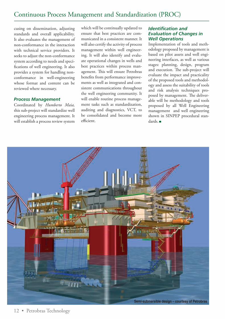
Semi-submersible design – courtesy of Petrobras
12 • Petrobras Technology
cusing on dissemination, adjusting standards and overall applicability. It also evaluates the management of non-conformance in the interaction with technical service providers. It seeks to adjust the non-conformance system according to needs and speci-fications of well engineering. It also provides a system for handling non-conformance in well-engineering whose format and content can be reviewed where necessary.
Process ManagementCoordinated by Humberto Maia, this sub-project will standardize well engineering process management. It will establish a process review system
which will be continually updated to ensure that best practices are com-municated in a consistent manner. It will also certify the activity of process management within well engineer-ing. It will also identify and evalu-ate operational changes in wells and best practices within process man-agement. This will ensure Petrobras benefits from performance improve-ments as well as integrated and con-sistent communications throughout the well engineering community. It will enable routine process manage-ment tasks such as standardization, auditing and diagnostics, VCT, to be consolidated and become more efficient.
Identification and Evaluation of Changes in Well OperationsImplementation of tools and meth-odology proposed by management is based on pilot assets and well engi-neering interfaces, as well as various stages: planning, design, program and execution. The sub-project will evaluate the impact and practicality of the proposed tools and methodol-ogy and assess the suitability of tools and risk analysis techniques pro-posed by management. The deliver-able will be methodology and tools proposed by all Well Engineering management and well engineering shown in SINPEP procedural stan-dards.
Continuous Process Management and Standardization (PROC)
14 • Petrobras Technology
P r o p o ç o P R O J
Project Management, Planning and Control (PROJ)
Deepwater projects are be-coming ever more com-plex. Gone are the days
when risks were ‘known’ and highly profitable giant fields could be de-veloped using conventional off-the-shelf technology. Large Oil compa-nies today face a series of deepwater production challenges created by smaller and more remote offshore oil and gas fields, lower permeabili-ty, and at times, higher temperatures and pressures also. In such circum-stances, it is vital for the Oil compa-ny to apply knowledge in three key areas: engineering, new technologies and project management.
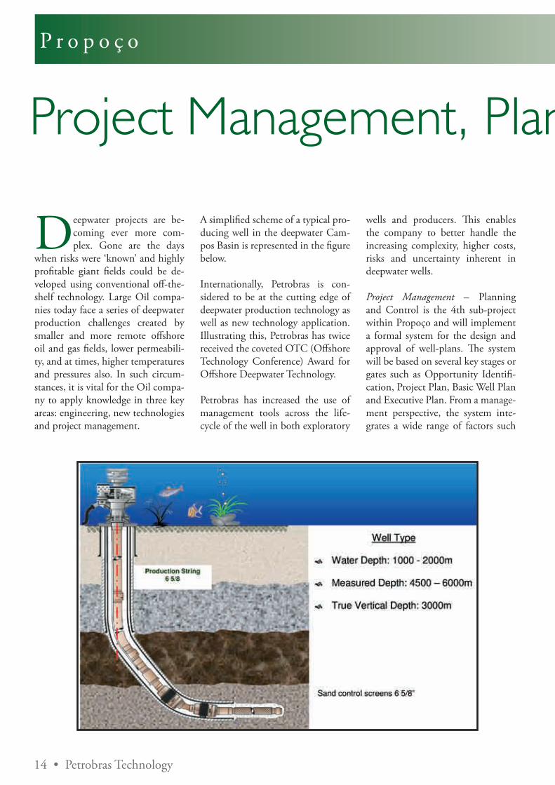
A simplified scheme of a typical pro-ducing well in the deepwater Cam-pos Basin is represented in the figure below.
Internationally, Petrobras is con-sidered to be at the cutting edge of deepwater production technology as well as new technology application. Illustrating this, Petrobras has twice received the coveted OTC (Offshore Technology Conference) Award for Offshore Deepwater Technology.
Petrobras has increased the use of management tools across the life-cycle of the well in both exploratory
wells and producers. This enables the company to better handle the increasing complexity, higher costs, risks and uncertainty inherent in deepwater wells.
Project Management – Planning and Control is the 4th sub-project within Propoço and will implement a formal system for the design and approval of well-plans. The system will be based on several key stages or gates such as Opportunity Identifi-cation, Project Plan, Basic Well Plan and Executive Plan. From a manage-ment perspective, the system inte-grates a wide range of factors such
Petrobras Technology • 15
P r o p o ç o P R O J
Project Management, Planning and Control (PROJ)as scope, timescale, cost, quality, risk, team, supply/procurement and communication.
Supported by broad participation from specialised business areas, well services and corporate functions, the PROJ project team has produced re-sults such as the following:
- Defining Front End Loading (FEL) needs for the well and personnel re-sponsible for different stages or gates of the well-plan.
International experience confirms that projects based on good reservoir
characterisation – seismic, rock and fluid analysis – linked with a detailed well-plan, show fewer time and cost deviations. The sub-project will look next at standardizing the contents of all well-engineering documents.
Further results include:
- Predicting probabilistic demand for well intervention. This allows production assets to estimate re-source usage for example rigs that are necessary to workover wells that show a drop in either productivity, or injectivity as in the case of water injectors.
- Planning and managing well cam-paigns within specific field develop-ments. Essentially this is a best prac-tices manual for well-engineering.
- Standardizing analytical procedures for well planning and construction. This enables costs to be allocated properly, increases the control of performance indicators and identi-fies priority tasks thereby improving process performance.
PROJ themes are shown below and are expected to be completed by the end of 2008.
16 • Petrobras Technology
P r o p o ç o C O N
Coordinated by Adolfo Polillo Filho, the fifth Propoço program is Knowledge and
Workforce Management (CON).
By attracting staff and developing their technical capabilities, Petrobras will be guaranteed a core of techni-cal and functional specialists irre-spective of future market conditions. Enabling this is the task of CON which will identify needs and de-velop competences within well engi-neering. It will utilize newly created mechanisms to post functional staff where required as well as develop technical specialists. Additionally, it will increase knowledge sharing by integrating technical communities, information databases and technical standards. The CON is structured in 6 sub-projects. Three sub-projects are currently underway – Critical Competences, HR Attraction & Reten-tion and Project Directives. Another related to ‘best practices within the community’ has been completed. A further two sub-projects are yet to commence – firstly consolidating di-rectives for projects, well plans and engineering methods and secondly automating well plans.
Coordinated by Valdo Ferreira Ro-drigues, Critical Competences will se-lect and help develop a broad range of skills and competences critical to Well Engineering. By considering present and future workforce require-ments, this sub-project will meet me-dium and long needs generated by diverse well engineering specialities.
Furthermore, it will generate career paths and professional development plans that offer specialized training courses corresponding to Master or Doctorate qualifications.
Development is based on existing concepts of Knowledge Management within Petrobras’ program for Top HR competence. Principal compe-tences were highlighted from various technology intelligence networks and requirements generated by well directives. The project will guarantee staff training over the next 10 to 15 years, considering short, medium and long term objectives in order to create a critical mass of talent that will be unaffected by cyclical market conditions. Deliverables will include a career plan for each speciality that includes formal courses and on-the-job training.
Coordinated by Rui Passarelli the HR Attraction & Retention project is tasked with assessing labour require-ments for well engineering activities based on different technical func-tions and the nature of each task at hand – whether it is routine or spe-cial. As a result, the process of de-fining personnel needs and posting staff will become more efficient and less subjective. For instance, in the wells area, the process considers the numbers of rig-based personnel and the need for specialized personnel.
Coordinated by José Eduardo de Lima Garcia the Directives sub-proj-ect will find the most efficient way of
well construction by standardizing corporate directives. Standardiza-tion will be readily applied to well construction projects where similar scenarios exist, in accordance with Petrobras’ best practices.
The fourth sub-project ‘Implemen-tation of best engineering practices with the well engineering com-munity’ includes a total of 15 well construction directives that have been established. Of these, 10 have already been validated within the company, in the following areas:
Geomechanics, Well Control, Well start-up, Directional Drilling, Bits, Drilling Fluids, Casing and Cementing, Well Geometry and Drillstring, Completion Fluids, Sand Control.
5 further directives are currently be-ing evaluated:
Formation Stimulation, Completion, Formation Evaluation, Well Abandonment,Intelligent Completions.
Upon conclusion of the sub-project, all 15 Directives will become com-pany wide standards for well con-struction.
Knowledge and Workforce Management (CON)
Petrobras Technology • 17
Sponsored by Bear ingPoint
Business Process Management: a key requirement to achieve results in the Oil & Gas Industry
The profi tability of oil & gas companies is subject to two
great risks that contribute toward the volatility of fi nancial performance. Th e fi rst risk is the variation of the price of the “commodity”, which is regulated by the market and interna-tional policies. Th e second risk is the operational effi ciency which is infl u-enced by the operational resources restrictions, technological barriers and management diffi culties.
As the organizations have very lit-tle infl uence on the price, the focus should be aimed at the pursuit of op-erational effi ciency. It is even more critical in the Exploration & Pro-duction area where the operational complexity, the level of uncertainty and restriction are much higher.
What are the “globally integrated companies” doing to improve their operational effi ciency? Th e main initiatives are related to: Cost Op-timization, Asset Management, In-tegration of Technologies, Business Intelligence, “Digital Oil Field of the Future (DOFF)” and Optimization of Operational Critical Resources.
Among the initiatives’ key success factors, there is an essential and common element to them all: the need to standardize, optimize and manage the business processes. Th is
practice is known as BPM – Busi-ness Process Management.
A complete BPM solution is a struc-tured approach employing methods, policies, metrics, management prac-tices and software tools to manage and continuously optimize an or-ganization’s activities and processes.
Th e employment of BPM technology allows management, at any point of the value chain, to understand the process fl ow and existing rules in application, infrastructure and operational processes as well as manage them directly with a unifi ed vision allowing for an adaptive management that takes into consideration the new technologies and market demands.
BPM enables agility in business in the following:
1. Real time availability of informa-tion that increases c-level manage-ment reliability and accuracy in the rapid decision making process.
2. Signifi cant time reduction in busi-ness process revision due to the clear defi nition of responsibilities and re-quirements.
3. Agility in process changes due to consensus, collaboration and visibility obtained.
With the objective of providing the necessary agility in business and as well as the expected benefi ts, BPM uses tools that integrate the diff erent technologies supporting the entire life cycle of the process in its phases of defi nition, development, execution, maintenance, analysis and optimization, and is named BPMS (Business Process Management Suite). Th ese tools make mapping, reproducing, simulation and analysis possible, allowing for anticipated and eff ective action.
Th e profi tability of oil & gas companies is directly related to the operational effi ciency that must be supported by an optimized management of the business processes. An optimized business process management depends fundamentally on the adoption and usage of the BPM concepts and tools implementation.
By Eduardo Raffaini, Senior Manager - Oil&Gas - E&P Practice Leader and Fabiano Sannino, Manager - Oil&Gas - E&P Practice
BearingPoint, Inc. (NYSE: BE) is one of
the world´'’s largest providers of manage-
ment and technology consulting services
to Global 2000 companies and government
organizations in 60 countries worldwide and
has over 17,000 employees. For nearly 100
years, BearingPoint professionals have built
a reputation for knowing what it takes to
help clients achieve their goals, and work-
ing closely with them to get the job done.
For more information, visit the Company’
website at www.BearingPoint.com.
18 • Petrobras Technology
We l l Te c h n o l o g y
The 200th Horizontal Open-Hole Gravel Packing Operation in the Campos Basin: A Milestone in the History of Petrobras Completion Practices in Ultra-deepwatersL.C.C. Marques, L.C.A.Paixão, V.P.Barbosa, M.O.Martins, A.Calderon, C. A. Pedroso, L.H.C. Fernandes, J.A. Melo, C. M. Chagas, N. J. Denadai, Petrobras SA.
The most prolific reservoirs in the CB (Campos Basin) are the Upper Cretaceous and
Tertiary turbidites. These high-per-meability (circa 1000 - 8000 mD), stacked and amalgamated reservoirs are spread over in shallow, deep and ultra-deepwater within the Basin as shown in Figure 1. Dictated by the depositional model associated to turbidites, the sand uniformity of these poorly or un-consolidated sand lenses vary quite a bit. The presence of reactive shale streaks is recurrent in some of these turbidites.
As a trend in many other offshore basins in the world, the first oil dis-coveries (in the early 1980s) in tur-bidites were located in shallow wa-ters of CB. These good exploratory results have propelled us to move progressively from shallow to ultra-deepwater scenarios. However, since the pioneer oil discoveries we have realized that a sand management strategy was necessary to achieve the desirable levels of production.
In fact, sand control is an umbrella term comprising different approach-es to dealing with sand production problems. Different sand control methods are known: frac-pack, chemical consolidation of sand grains, use of screens: sintered mesh, conventional and expandable (ESS), use of slotted liners, gravel packing, inter alia.
Figure 1 – Main Oilfields in Campos Basin
Petrobras philosophy is one of zero tolerance concerning sand produc-tion in offshore fields lest the gov-erning parameters for sand produc-tion are not well established for the vast majority of actual field situa-tions and they may change along the life-span of the wells. Should there be the slightest chance of sand production, a sand control method is installed in our wells. In essence, this preventive approach to sand exclusion stems from the following
facts: wellbore integrity concerns, prohibitively high well intervention costs, the need to maximize produc-tion rates, to achieve a maximum completion efficiency index, safety concerns, payback economics, and incapability of sand-dealing in top-side equipments. In fact, our off-shore production facilities have not been designed to process sand-bear-ing crude oils.
Even though there is no such a thing as a panacea to deal with all sand con-
Petrobras Technology • 19
The 200th Horizontal Open-Hole Gravel Packing Operation in the Campos Basin: A Milestone in the History of Petrobras Completion Practices in Ultra-deepwaters
trol problems, gravel packing has es-tablished something of a reputation along the years. It is considered the vintage alternative for sand control in horizontal open-hole wells with good vertical permeability, non-uni-form sands and no lamination. In addition to that, filling up the screen - wellbore annulus of an open-hole horizontal well - with properly sized gravel, creates a secondary barrier to the migrating sand grains, thus in-creasing the longevity of the gravel pack screens.
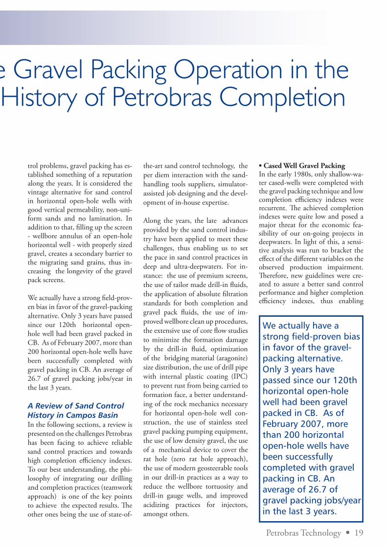
We actually have a strong field-prov-en bias in favor of the gravel-packing alternative. Only 3 years have passed since our 120th horizontal open-hole well had been gravel packed in CB. As of February 2007, more than 200 horizontal open-hole wells have been successfully completed with gravel packing in CB. An average of 26.7 of gravel packing jobs/year in the last 3 years.
A Review of Sand Control History in Campos BasinIn the following sections, a review is presented on the challenges Petrobras has been facing to achieve reliable sand control practices and towards high completion efficiency indexes. To our best understanding, the phi-losophy of integrating our drilling and completion practices (teamwork approach) is one of the key points to achieve the expected results. The other ones being the use of state-of-
the-art sand control technology, the per diem interaction with the sand-handling tools suppliers, simulator-assisted job designing and the devel-opment of in-house expertise.
Along the years, the late advances provided by the sand control indus-try have been applied to meet these challenges, thus enabling us to set the pace in sand control practices in deep and ultra-deepwaters. For in-stance: the use of premium screens, the use of tailor made drill-in fluids, the application of absolute filtration standards for both completion and gravel pack fluids, the use of im-proved wellbore clean up procedures, the extensive use of core flow studies to minimize the formation damage by the drill-in fluid, optimization of the bridging material (aragonite) size distribution, the use of drill pipe with internal plastic coating (IPC) to prevent rust from being carried to formation face, a better understand-ing of the rock mechanics necessary for horizontal open-hole well con-struction, the use of stainless steel gravel packing pumping equipment, the use of low density gravel, the use of a mechanical device to cover the rat hole (zero rat hole approach), the use of modern geosteerable tools in our drill-in practices as a way to reduce the wellbore tortuosity and drill-in gauge wells, and improved acidizing practices for injectors, amongst others.
• Cased Well Gravel PackingIn the early 1980s, only shallow-wa-ter cased-wells were completed with the gravel packing technique and low completion efficiency indexes were recurrent. The achieved completion indexes were quite low and posed a major threat for the economic fea-sibility of our on-going projects in deepwaters. In light of this, a sensi-tive analysis was run to bracket the effect of the different variables on the observed production impairment. Therefore, new guidelines were cre-ated to assure a better sand control performance and higher completion efficiency indexes, thus enabling
We actually have a strong field-proven bias in favor of the gravel-packing alternative. Only 3 years have passed since our 120th horizontal open-hole well had been gravel packed in CB. As of February 2007, more than 200 horizontal open-hole wells have been successfully completed with gravel packing in CB. An average of 26.7 of gravel packing jobs/year in the last 3 years.
20 • Petrobras Technology
The 200th Horizontal Open-Hole Gravel Packing Operation
us to handle the more challenging problems associated with deep and ultra-deepwaters.
• Frac PacksThe frac pack technique is our first sand control option to complete ver-tical and low-angle-deviated-cased-wells where neither mechanical re-strictions nor a near gas-oil and/or water-oil contact exists.
As anticipated by a suite of studies, the use of the frac pack technique in Marlim field (CB) has produced completion efficiency indexes of up to 100 % in several situations. This is because the creation of a high-conductive fracture in the formation counterbalances the flow restrictions that take place in the perforations. However, HOHGP wells have been adopted as the best-in-class well ar-chitecture to our newest sand control projects in CB. Due to that, the frac pack applications have been limited to some very specific cased-well ap-plications. For instance, in vertical or slightly deviated re-completion jobs or when two or more pay zones are to be re-completed for selective production.
Among the technology innovations that have been introduced to our frac pack operations are the follow-ing: washpipeless frac pack tools for 7” casing (to reduce the threats of getting the washpipe stuck at the end of the pumping job), large bore frac pack tools, and intelligent and selective completions with three in-tervals being completed with remote control over two.
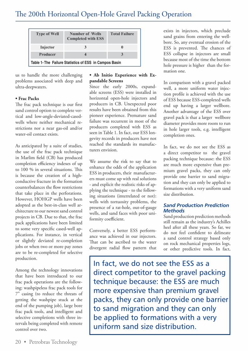
• Ab Initio Experience with Ex-pandable Screens Since the early 2000s, expand-able screens (ESS) were installed in horizontal open-hole injectors and producers in CB. Unexpected poor results have been obtained from this pioneer experience. Premature sand failure was recurrent in most of the producers completed with ESS as seen in Table 1. In fact, our ESS lon-gevity records in producers have not reached the standards its manufac-turers envision.
We assume the risk to say that to enhance the odds of the application ESS in producers, their manufactur-ers must come up with real solutions - and explicit the realistic risks of ap-plying the technique - to the follow-ing situations (interrelated or not): wells with tortuosity problems, the presence of a rat-hole, out-of-gauge wells, and sand faces with poor uni-formity coefficient.
Conversely, a better ESS perform-ance was achieved in our injectors. That can be ascribed to the water divergent radial flow pattern that
exists in injectors, which preclude sand grains from entering the well-bore. So, any eventual erosion of the ESS is prevented. The chances of ESS collapse in injectors are small because most of the time the bottom hole pressure is higher than the for-mation one.
In comparison with a gravel packed well, a more uniform water injec-tion profile is achieved with the use of ESS because ESS-completed wells end up having a larger wellbore. Another advantage of the ESS over gravel pack is that a larger wellbore diameter provides more room to run in hole larger tools, e.g. intelligent completion ones.
In fact, we do not see the ESS as a direct competitor to the gravel packing technique because: the ESS are much more expensive than pre-mium gravel packs, they can only provide one barrier to sand migra-tion and they can only be applied to formations with a very uniform sand size distribution.
Sand Production Prediction Methods Sand production prediction methods still remain as the industry’s Achilles heel after all these years. So far, we do not feel confident to delineate a sand control strategy based only on rock mechanical properties logs, or other predictive tools. In fact,
Table 1- The Failure Statistics of ESS in Campos Basin
In fact, we do not see the ESS as a direct competitor to the gravel packing technique because: the ESS are much more expensive than premium gravel packs, they can only provide one barrier to sand migration and they can only be applied to formations with a very uniform sand size distribution.
Petrobras Technology • 21
The 200th Horizontal Open-Hole Gravel Packing Operation
little does one realize how these interdependent properties can change over time. For instance, when the reservoir pressure depletes or the water-cut builds up. No logs can really predict time-dependent properties at all. Literature data corroborates that attempts to create a sand control policy based solely on logs have not provided good results. We are also aware that a consistent sand production simulator (if it ever exists) would require a list of “not-so-easy-to-get” input parameters, or “ad hoc” boundary conditions, such as: characterization of the time-dependent mechanical properties of the rock, the erosion and sand grain transport in formation and through the well by the percolating fluids, the sand production dependence on reservoir depletion, and thermo hydraulics, just to name a few. The reality is that in the vast majority of situations the input data required to properly run the “simulation” is neither available nor easy to attain.
A recent paper published by Het-tema et al reports the use of an empirical method to predict sand production behavior in the Statfjord field, North Sea, where in the past 10 years none of the wells have been completed with sand control devices. It is also reported that the Statfjord topside facilities can handle quite a large amount of produced sand from the wells. Yet, the yearly sand pro-duction on each field platform hov-ers around 50 to 100 metric tons. Among the conclusions of those au-thors is that for the late-life of the field, the majority of the wells to be drilled will demand a sand control method. It is also reported that the results of the sand production simu-lation have to be matched with field data and tempered with sound engi-neering judgment. Amazingly, there is no mention on cased-well collapse in the field.
In fact, we have a bias against this sand management strategy because: our top-sides were not designed to
handle much sand; concerns that the abrasive moving sand grains can erode the sub-surface safety valve, the choke and top-side valves, thus rendering the well uncontrolled and fears that the void in the formation around the casing, created by the sand grains migration, can promote the formation collapse thus leading to a catastrophic casing failure.
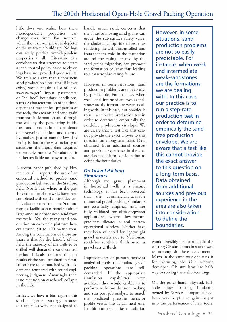
However, in some situations, sand production problems are not so eas-ily predictable. For instance, when weak and intermediate weak-sand-stones are the formations we are deal-ing with. In this case, our practice is to run a step-rate production test in order to determine empirically the sand-free production envelope. We are aware that a test like this can-not provide the exact answer to this question on a long-term basis. Data obtained from additional sources and previous experience in the area are also taken into consideration to define the boundaries.
On Gravel Packing Simulators Although the gravel placement in horizontal wells is a mature technology, it has been observed that the commercially-available numerical gravel packing simulators are essentially empirical and not fully validated for ultra-deepwater applications where low-fracture gradients dictates a real narrow operational window. Neither have they been validated for lightweight gravel materials nor to Newtonian solid-free synthetic fluids used as gravel carrier fluids.
Improvements of pressure-behavior analytical tools to simulate gravel packing operations are still demanded. If the appropriate simulation capabilities were available, they would enable us to perform real-time decision making and run post-job analysis to match the predicted pressure behavior profile versus the actual field one. In this context, a faster solution
would possibly be to upgrade the existing GP simulators in such a way to accomplish these assignments. Much in the same way one uses it for fracturing jobs. Our in-house developed GP simulator are half-way to solving these shortcomings.
On the other hand, physical, full-scale, gravel packing simulators owned by Service Companies have been very helpful to gain insight into the performance of new tools,
However, in some situations, sand production problems are not so easily predictable. For instance, when weak and intermediate weak-sandstones are the formations we are dealing with. In this case, our practice is to run a step-rate production test in order to determine empirically the sand-free production envelope. We are aware that a test like this cannot provide the exact answer to this question on a long-term basis. Data obtained from additional sources and previous experience in the area are also taken into consideration to define the boundaries.
22 • Petrobras Technology
The 200th Horizontal Open-Hole Gravel Packing Operation
placement techniques, to optimize pumping schedules and to validate our numerical gravel packing simu-lators as well. Different simulations have been run to shed light on very specific problems. For instance: the use of lightweight gravel materials, to evaluate the performance of vis-cous and viscoelastic fluids, diverter valves and to optimize the alpha-wave height when the screens are centralized (or not).
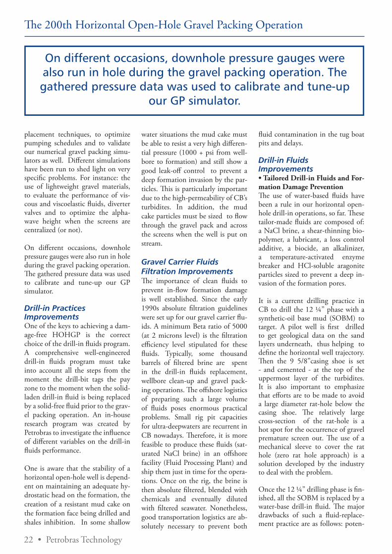
On different occasions, downhole pressure gauges were also run in hole during the gravel packing operation. The gathered pressure data was used to calibrate and tune-up our GP simulator.
Drill-in Practices ImprovementsOne of the keys to achieving a dam-age-free HOHGP is the correct choice of the drill-in fluids program. A comprehensive well-engineered drill-in fluids program must take into account all the steps from the moment the drill-bit tags the pay zone to the moment when the solid-laden drill-in fluid is being replaced by a solid-free fluid prior to the grav-el packing operation. An in-house research program was created by Petrobras to investigate the influence of different variables on the drill-in fluids performance.
One is aware that the stability of a horizontal open-hole well is depend-ent on maintaining an adequate hy-drostatic head on the formation, the creation of a resistant mud cake on the formation face being drilled and shales inhibition. In some shallow
water situations the mud cake must be able to resist a very high differen-tial pressure (1000 + psi from well-bore to formation) and still show a good leak-off control to prevent a deep formation invasion by the par-ticles. This is particularly important due to the high-permeability of CB’s turbidites. In addition, the mud cake particles must be sized to flow through the gravel pack and across the screens when the well is put on stream.
Gravel Carrier Fluids Filtration Improvements The importance of clean fluids to prevent in-flow formation damage is well established. Since the early 1990s absolute filtration guidelines were set up for our gravel carrier flu-ids. A minimum Beta ratio of 5000 (at 2 microns level) is the filtration efficiency level stipulated for these fluids. Typically, some thousand barrels of filtered brine are spent in the drill-in fluids replacement, wellbore clean-up and gravel pack-ing operations. The offshore logistics of preparing such a large volume of fluids poses enormous practical problems. Small rig pit capacities for ultra-deepwaters are recurrent in CB nowadays. Therefore, it is more feasible to produce these fluids (sat-urated NaCl brine) in an offshore facility (Fluid Processing Plant) and ship them just in time for the opera-tions. Once on the rig, the brine is then absolute filtered, blended with chemicals and eventually diluted with filtered seawater. Nonetheless, good transportation logistics are ab-solutely necessary to prevent both
fluid contamination in the tug boat pits and delays.
Drill-in Fluids Improvements• Tailored Drill-in Fluids and For-mation Damage PreventionThe use of water-based fluids have been a rule in our horizontal open-hole drill-in operations, so far. These tailor-made fluids are composed of: a NaCl brine, a shear-thinning bio-polymer, a lubricant, a loss control additive, a biocide, an alkalinizer, a temperature-activated enzyme breaker and HCl-soluble aragonite particles sized to prevent a deep in-vasion of the formation pores.
It is a current drilling practice in CB to drill the 12 ¼” phase with a synthetic-oil base mud (SOBM) to target. A pilot well is first drilled to get geological data on the sand layers underneath, thus helping to define the horizontal well trajectory. Then the 9 5/8”casing shoe is set - and cemented - at the top of the uppermost layer of the turbidites. It is also important to emphasize that efforts are to be made to avoid a large diameter rat-hole below the casing shoe. The relatively large cross-section of the rat-hole is a hot spot for the occurrence of gravel premature screen out. The use of a mechanical sleeve to cover the rat hole (zero rat hole approach) is a solution developed by the industry to deal with the problem.
Once the 12 ¼” drilling phase is fin-ished, all the SOBM is replaced by a water-base drill-in fluid. The major drawbacks of such a fluid-replace-ment practice are as follows: poten-
On different occasions, downhole pressure gauges were also run in hole during the gravel packing operation. The gathered pressure data was used to calibrate and tune-up
our GP simulator.
Petrobras Technology • 23
The 200th Horizontal Open-Hole Gravel Packing Operation
tial to formation damage, involves complex logistics, and is time-con-suming. In fact, the rig’s drilling system must be meticulously clean after the SOBM has been sent to a mud re-processing facility onshore. It takes circa 2-3 days for the whole fluid replacement to be carried-out. Just after that, the new water-base drill-in fluid can prepared onboard - or brought onboard - to drill the 8 ½”phase to the final depth. Be-fore running in hole the gravel pack screens, another drill string, equipped with riser and casing-scrappers, magnets and a junk-bas-ket, is run in hole to wellbore clean-up and displace the water-based drill-in fluid by an absolute filtered completion brine. During this dis-placement, annular fluid velocities of circa 300 ft/minute are applied to create a real fine mud cake (less than 1 mm thick). By applying an optimized fluid velocity, a trade-off between no formation damage and no significant fluid losses to forma-tion (during the gravel pump job) is achieved.
• SOBM for Drill-in-Fluids and a Solid-Free Synthetic Fluid for Gravel-PackingThe practice of using SOBM to drill-in the 8 ½” phase to con-struct a horizontal open-hole well to be gravel packed, presents a series of advantages over the current field practice of replacing this fluid by a water-based drill-in one, as follows: superior wellbore stability, better lu-bricity, higher ROP, better shale in-hibition, and rig time optimization.
A suite of laboratory experiments and full-scale simulations were car-
ried out to specify the SOBM for-mulation to drill-in the 8 ½” phase. In this study the following issues were investigated: optimum parti-cle size distribution, lubricity, shale inhibition, wellbore cleanup proce-dures, optimum rheological prop-erties, and mechanical plugging of screen weaves by the SOBM sized particles. By the same token, tests and simulations were carried out with the so-called solid-free syn-thetic fluid (SFSF) to be used as a gravel carrier fluid. The goal was to optimize its Newtonian behavior, to check for its incompatibilities with both the drill-in fluid and reactive shales, to minimize formation dam-age, dune creation, and to verify its wetting properties. Martins et al. de-scribe the approaches used to tailor both a SOBM and a SFSF for our gravel packing operations in Marlim field.
Horizontal Wells Acidizing ConcernsDiversion is a key point for the ef-ficiency of the post gravel packing acid-treatments of long horizontal open-hole wells to achieve either the desired seawater injection quotas or the maximum productivity.
A technical agreement was signed by Petrobras and a Service Company to develop a gravel packing tool that can be converted to an acidizing one after the gravel packing job has been performed. This one-trip tool shows a good mechanical diversion for the treating fluids. Its use has enhanced the efficiency of our acid treatments. Pereira et al. also describe the de-velopment of a tailored coiled-tub-ing-conveyed acidizing tool for post-gravel packing applications.
Another matter of concern is the excessive corrosion of the screens that may take place in acidizing operations. Therefore, care must be taken to prevent the screens from being damaged during the acid treat-ments.
Corrosion tests carried out in our laboratory have shown that the al-loys the majority of the commer-cial gravel pack screens are made of - 13Cr stainless steel - are very sen-sitive to concentrated inorganic acid contact. These corrosion tests have also allowed us to conclude that just a few commercial acid inhibitors are able to provide the adequate protec-tion to the screens.
Our injectors are not flowed back prior to water injection, so they (all) require a treatment to dissolve the thin mud cake and to remove the formation damage. Preventing the injector screens from being corroded by the acidizing fluids is simple. This can be achieved by preventing a long contact-time of these fluids with the screens. The use of high acid pump rates and over flush means the screens with non-acidic fluids can overcome the corrosion problem.
In general, our prod ucers have achieved high completion efficien-cies thus not demanding post-treat-ments for damage removal. On a few occasions, however, our producers had to be acidized.
However, acidizing a producer can be tricky. One must take into con-sideration that, under actual down
Another matter of concern is the excessive corrosion of the screens that may take place in acidizing operations.
Therefore, care must be taken to prevent the screens from being damaged during the acid treatments.
24 • Petrobras Technology
The 200th Horizontal Open-Hole Gravel Packing Operation
hole conditions, the contact-time of the bottom side of the screens with the partially-spent acid can be long enough to promote excessive cor-rosion. One also has to realize that dog legs and tortuosities (hills and valleys) are frequent features in the geometry of horizontals. Besides, a horizontal producer starts clean up from the heel side to the toe side and this process can take a long time. In fact, doubts remain whether the par-tially-spent acid accumulated in the lowermost valleys of the horizontal well is actually produced or not.
sion to be completed, and fluids re-turns are not apt enough; the use of lightweight proppant (1.25 g/cm3 specific gravity, 0,85 g/cm3 bulk density), as a gravel material, has positively widened the operational window of our HOHGP operations. The advantages of using lightweight proppant over the conventional one are briefly described in the follow-ing lines. The settling velocity of a given particle in a Newtonian fluid is directly proportional to the spe-cific gravity contrast (SGparticle mi-nus SGcarrier fluid), the lightweight proppant has a pretty much smaller
conclusions of those authors is that the ultra-lightweight proppant can overcome the vast majority of the problems associated with HOHGP operations in long horizontal wells and/or in ultra-deepwaters.
• Performing the Gravel Packing Job with Fluid Returns Lined-up into the FlowlineLow fracture gradient formations are typical in ultra-deepwaters and demand low bottom hole pumping pressures to prevent the formation from being fractured along the grav-el packing pumping job. We have On the other hand, the
(drill-in) mud cake lift-off pressure is designed to be as low as possible to enhance the clean up process by the producing fluids. In labora-tory conditions lift-off pres-sures as low as 10 psi can be achieved.
Ways to Reduce the Bottom Hole Pressure During Gravel Packing Operations• Use of Lightweight Gravel MaterialsCommercially-available high-per-meability synthetic proppants (16-20 and 20-40 US mesh, specific gravity ranging from 2.65 to 2.73 g/cm3) have established a good rep-utation as a gravel material in our conventional horizontal open-hole gravel packing operations. The com-bination of Tiffin et al. criteria for gravel size selection, the use of larger gauge 13Cr premium screen gauges (170 – 250 microns), and synthetic gravel has provided excellent results (high productivity and high longev-ity) where fine migration is not an important issue.
On the other hand, where real con-cerns exist in terms of conventional-gravel placement, viz., the existence of a washed-out zone, a low fracture gradient, a long open hole exten-
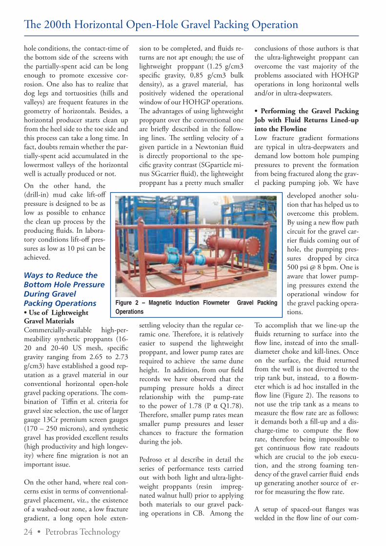
Figure 2 – Magnetic Induction Flowmeter Gravel Packing Operations
settling velocity than the regular ce-ramic one. Therefore, it is relatively easier to suspend the lightweight proppant, and lower pump rates are required to achieve the same dune height. In addition, from our field records we have observed that the pumping pressure holds a direct relationship with the pump-rate to the power of 1.78 (P α Q1.78). Therefore, smaller pump rates mean smaller pump pressures and lesser chances to fracture the formation during the job.
Pedroso et al describe in detail the series of performance tests carried out with both light and ultra-light-weight proppants (resin impreg-nated walnut hull) prior to applying both materials to our gravel pack-ing operations in CB. Among the
developed another solu-tion that has helped us to overcome this problem. By using a new flow path circuit for the gravel car-rier fluids coming out of hole, the pumping pres-sures dropped by circa 500 psi @ 8 bpm. One is aware that lower pump-ing pressures extend the operational window for the gravel packing opera-tions.
To accomplish that we line-up the fluids returning to surface into the flow line, instead of into the small-diameter choke and kill-lines. Once on the surface, the fluid returned from the well is not diverted to the trip tank but, instead, to a flowm-eter which is ad hoc installed in the flow line (Figure 2). The reasons to not use the trip tank as a means to measure the flow rate are as follows: it demands both a fill-up and a dis-charge-time to compute the flow rate, therefore being impossible to get continuous flow rate readouts which are crucial to the job execu-tion, and the strong foaming ten-dency of the gravel carrier fluid ends up generating another source of er-ror for measuring the flow rate.
A setup of spaced-out flanges was welded in the flow line of our com-
Petrobras Technology • 25
The 200th Horizontal Open-Hole Gravel Packing Operation
pletion rigs to which the flow meter of the Service Company can be at-tached just prior to the gravel pack-ing operation. Adequate flow meters have been designed to operate from these floating rigs without compro-mising the quality of information because the chosen devices are not much affected by the sea heave.
To our best understanding, the way we (successfully) have applied the flowmeter to the flow line, as a means to extend the window of our gravel packing operations in ultra-deepwaters, is a technology innova-tion that has never been used by the industry before.
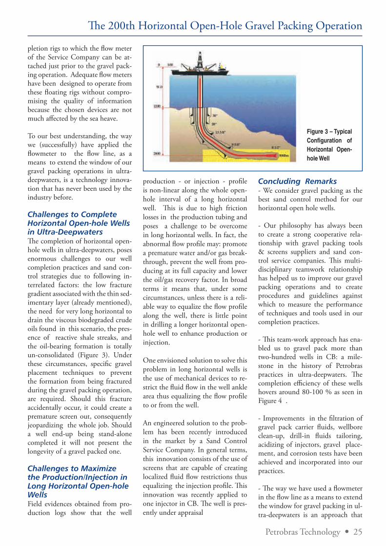
Challenges to Complete Horizontal Open-hole Wells in Ultra-Deepwaters The completion of horizontal open-hole wells in ultra-deepwaters, poses enormous challenges to our well completion practices and sand con-trol strategies due to following in-terrelated factors: the low fracture gradient associated with the thin sed-imentary layer (already mentioned), the need for very long horizontal to drain the viscous biodegraded crude oils found in this scenario, the pres-ence of reactive shale streaks, and the oil-bearing formation is totally un-consolidated (Figure 3). Under these circumstances, specific gravel placement techniques to prevent the formation from being fractured during the gravel packing operation, are required. Should this fracture accidentally occur, it could create a premature screen out, consequently jeopardizing the whole job. Should a well end-up being stand-alone completed it will not present the longevity of a gravel packed one.
Challenges to Maximize the Production/Injection in Long Horizontal Open-hole Wells Field evidences obtained from pro-duction logs show that the well
production - or injection - profile is non-linear along the whole open-hole interval of a long horizontal well. This is due to high friction losses in the production tubing and poses a challenge to be overcome in long horizontal wells. In fact, the abnormal flow profile may: promote a premature water and/or gas break-through, prevent the well from pro-ducing at its full capacity and lower the oil/gas recovery factor. In broad terms it means that, under some circumstances, unless there is a reli-able way to equalize the flow profile along the well, there is little point in drilling a longer horizontal open-hole well to enhance production or injection.
One envisioned solution to solve this problem in long horizontal wells is the use of mechanical devices to re-strict the fluid flow in the well ankle area thus equalizing the flow profile to or from the well.
An engineered solution to the prob-lem has been recently introduced in the market by a Sand Control Service Company. In general terms, this innovation consists of the use of screens that are capable of creating localized fluid flow restrictions thus equalizing the injection profile. This innovation was recently applied to one injector in CB. The well is pres-ently under appraisal
Concluding Remarks - We consider gravel packing as the best sand control method for our horizontal open hole wells.
- Our philosophy has always been to create a strong cooperative rela-tionship with gravel packing tools & screens suppliers and sand con-trol service companies. This multi-disciplinary teamwork relationship has helped us to improve our gravel packing operations and to create procedures and guidelines against which to measure the performance of techniques and tools used in our completion practices.
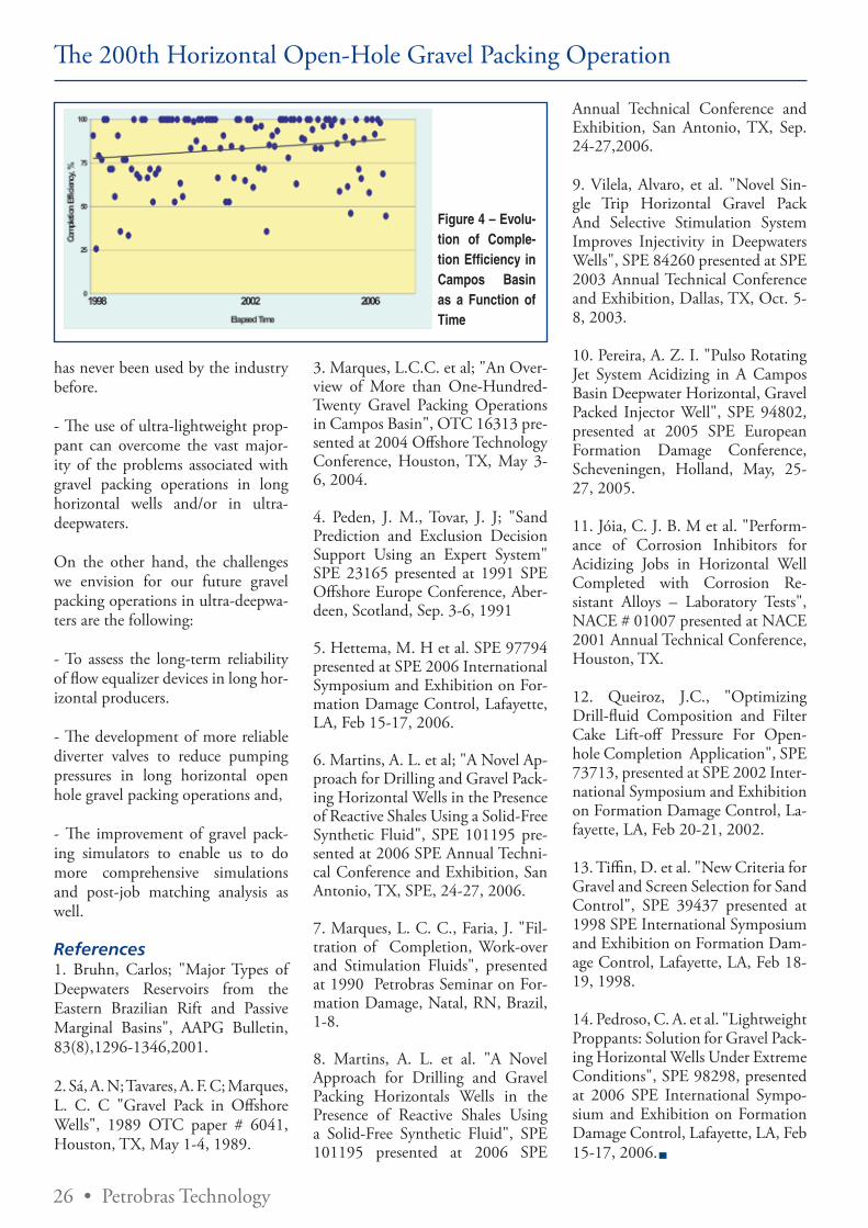
- This team-work approach has ena-bled us to gravel pack more than two-hundred wells in CB: a mile-stone in the history of Petrobras practices in ultra-deepwaters. The completion efficiency of these wells hovers around 80-100 % as seen in Figure 4 .
- Improvements in the filtration of gravel pack carrier fluids, wellbore clean-up, drill-in fluids tailoring, acidizing of injectors, gravel place-ment, and corrosion tests have been achieved and incorporated into our practices.
- The way we have used a flowmeter in the flow line as a means to extend the window for gravel packing in ul-tra-deepwaters is an approach that
Figure 3 – Typical Configuration of Horizontal Open-hole Well
26 • Petrobras Technology
The 200th Horizontal Open-Hole Gravel Packing Operation
has never been used by the industry before.
- The use of ultra-lightweight prop-pant can overcome the vast major-ity of the problems associated with gravel packing operations in long horizontal wells and/or in ultra-deepwaters.
On the other hand, the challenges we envision for our future gravel packing operations in ultra-deepwa-ters are the following:
- To assess the long-term reliability of flow equalizer devices in long hor-izontal producers.
- The development of more reliable diverter valves to reduce pumping pressures in long horizontal open hole gravel packing operations and,
- The improvement of gravel pack-ing simulators to enable us to do more comprehensive simulations and post-job matching analysis as well.
References1. Bruhn, Carlos; "Major Types of Deepwaters Reservoirs from the Eastern Brazilian Rift and Passive Marginal Basins", AAPG Bulletin, 83(8),1296-1346,2001.
2. Sá, A. N; Tavares, A. F. C; Marques, L. C. C "Gravel Pack in Offshore Wells", 1989 OTC paper # 6041, Houston, TX, May 1-4, 1989.
Figure 4 – Evolu-tion of Comple-tion Efficiency in Campos Basin as a Function of Time
3. Marques, L.C.C. et al; "An Over-view of More than One-Hundred-Twenty Gravel Packing Operations in Campos Basin", OTC 16313 pre-sented at 2004 Offshore Technology Conference, Houston, TX, May 3-6, 2004.
4. Peden, J. M., Tovar, J. J; "Sand Prediction and Exclusion Decision Support Using an Expert System" SPE 23165 presented at 1991 SPE Offshore Europe Conference, Aber-deen, Scotland, Sep. 3-6, 1991
5. Hettema, M. H et al. SPE 97794 presented at SPE 2006 International Symposium and Exhibition on For-mation Damage Control, Lafayette, LA, Feb 15-17, 2006.
6. Martins, A. L. et al; "A Novel Ap-proach for Drilling and Gravel Pack-ing Horizontal Wells in the Presence of Reactive Shales Using a Solid-Free Synthetic Fluid", SPE 101195 pre-sented at 2006 SPE Annual Techni-cal Conference and Exhibition, San Antonio, TX, SPE, 24-27, 2006.
7. Marques, L. C. C., Faria, J. "Fil-tration of Completion, Work-over and Stimulation Fluids", presented at 1990 Petrobras Seminar on For-mation Damage, Natal, RN, Brazil, 1-8.
8. Martins, A. L. et al. "A Novel Approach for Drilling and Gravel Packing Horizontals Wells in the Presence of Reactive Shales Using a Solid-Free Synthetic Fluid", SPE 101195 presented at 2006 SPE
Annual Technical Conference and Exhibition, San Antonio, TX, Sep. 24-27,2006.
9. Vilela, Alvaro, et al. "Novel Sin-gle Trip Horizontal Gravel Pack And Selective Stimulation System Improves Injectivity in Deepwaters Wells", SPE 84260 presented at SPE 2003 Annual Technical Conference and Exhibition, Dallas, TX, Oct. 5-8, 2003.
10. Pereira, A. Z. I. "Pulso Rotating Jet System Acidizing in A Campos Basin Deepwater Horizontal, Gravel Packed Injector Well", SPE 94802, presented at 2005 SPE European Formation Damage Conference, Scheveningen, Holland, May, 25-27, 2005.
11. Jóia, C. J. B. M et al. "Perform-ance of Corrosion Inhibitors for Acidizing Jobs in Horizontal Well Completed with Corrosion Re-sistant Alloys – Laboratory Tests", NACE # 01007 presented at NACE 2001 Annual Technical Conference, Houston, TX.
12. Queiroz, J.C., "Optimizing Drill-fluid Composition and Filter Cake Lift-off Pressure For Open-hole Completion Application", SPE 73713, presented at SPE 2002 Inter-national Symposium and Exhibition on Formation Damage Control, La-fayette, LA, Feb 20-21, 2002.
13. Tiffin, D. et al. "New Criteria for Gravel and Screen Selection for Sand Control", SPE 39437 presented at 1998 SPE International Symposium and Exhibition on Formation Dam-age Control, Lafayette, LA, Feb 18-19, 1998.
14. Pedroso, C. A. et al. "Lightweight Proppants: Solution for Gravel Pack-ing Horizontal Wells Under Extreme Conditions", SPE 98298, presented at 2006 SPE International Sympo-sium and Exhibition on Formation Damage Control, Lafayette, LA, Feb 15-17, 2006.

Petrobras Technology • 27
S p o n s o r e d b y
New technologies meet offshore challengesBy Ricardo Aboud, BJ Services Company
As part of a long-term energy plan, Petrobras has fast-tracked the development
of gas fields while maintaining traditional oil production. The most prominent of the new gas fields are in the offshore Espírito Santo and Santos basins, mostly in water depths greater than 1,000 m. Of course, interest in the reliable Campos basin will continue, and Petrobras is also exploring some new onshore frontiers, where tight gas is expected.
The drilling and completion challenges in these major offshore basins include geological uncertainties, a narrow operational window for drilling (low absorption pressure and elevated pore pressure), presence of reactive shales (which require high-performance drilling and completion fluids), and special well requirements (to improve reservoir drainage and compensate for low oil mobility).
In all three basins, Petrobras also expects to increase oil reserves from zones below thick (up to 2,000 ft) salt formations. The challenge in drilling through the salts is to maintain hole stability as salts (mainly tachyhydrites) tend to move after drilling. BJ Services has helped to overcome this problem by designing and pumping heavy (18.5 ppg) cement spacers and slurries with desired spacer stability (30 days with no settling) and slurry setting time.
Technical hurdlesIn the Campos basin, most sandstones (turbidites) have low pay zone heights, poor consolidation, median to fine sands, high porosity and permeability, low fracture gradients (<0.57 psi/ft), and heavy
oil. Most oil wells in Campos and Espírito Santo basins are completed as horizontal open-hole gravel packs, with more than 200 completed this way to date. In Santos basin, however, most wells will be gas wells - with bottomhole temperatures from 350 to 400 °F.
Completion tools for these wells must have noble metallurgy and sand control screens with high flow efficiency in order to provide long well life. Effective controls are required for water injection and production, especially careful zonal isolation.
With such a combination of challenging fields and expensive operations, the offshore scenario in Brazil calls for state-of-the-art research and technologies. Petrobras and other major companies operating in Brazil are promoting research programs on the most significant issues. However, many new high-performance technologies already can save time while maintaining a high benefit-to-cost ratio. Examples of novel technologies that BJ Services is using offshore Brazil include:
• Single-trip horizontal sand control completion tools that provide gravel and frac pack with stimulation in one trip, reducing rig time;
• Ultra-lightweight proppants for sand control, extending the window for effective horizontal well packing beyond 1,200 m;
• Coiled tubing rotating and pres-sure-cycling jetting tools, replacing coiled tubing straddle packers on long horizontal wells and reducing treatment time by a factor of 300 to 400%;
• Updated DP-2 stimulation vessels capable of operations from simple pumping jobs to complex hydraulic fracturing, as fast as 50 bpm;
• State-of-the-art, fit-for-purpose ce-menting units with high standards of HSE, including sound enclosures, fewer rotating parts, and remote control;
• Innovative acid systems with rela-tively neutral pH (~3), allowing wells to be treated via FPSO because of minimized corrosion effects;
• A full set of environmentally friendly cementing additives, in-cluding additives for gas-tight ce-ment slurries;
• Automated make-up rig equip-ment for making up well tubulars being run in the well, saving rig time and increasing safety;
• Efficient wellbore cleaning tools, minimizing formation damage;
• Effective completion fluid filtration systems, minimizing the amount of solids that could plug the formation and screens;
• Geosteering pipeline pigging, enhancing monitoring and helping establish pigging efficiency.
28 • Petrobras Technology
IntroductionCasing or liner drilling technique consists of drilling and casing si-multaneously. The casing or liner is used to transmit mechanical and hydraulic energy to the drill bit or to the drill shoe. The main reasons to use this technique are to reduce trip time, eliminate well conditioning time before running casing or liner into the well, overcome troublesome formations with well instability and loss circulation problems, and im-prove well control.
Casing and liner drilling techniques have been used mainly to solve well instabilities. In Brazil some tests have been done1. The main scenario to apply this technique is from land rig or offshore fixed platforms such as jack-up rig and TLP. Casing and lin-er drilling can also be applied from floating rig with surface BOP2.
There are basically three primary cas-ing drilling techniques available in the market. Casing Drilling® allows the BHA to be changed without tripping the casing. The others are Drilling with Casing® and EZCase®, which use a fixed cutter drill shoe.
This paper describes these techniques and the results of Casing Drilling® tests performed in Brazil
As most of the scenarios in Brazil are offshore deep water, the applica-tion of casing drilling techniques is strongly limited. That is the main reason liner drilling is being con-
sidered to solve well instabilities in this scenario. Then, this paper will also present the planning to apply, for the first time, liner drilling tech-nique in Brazil.
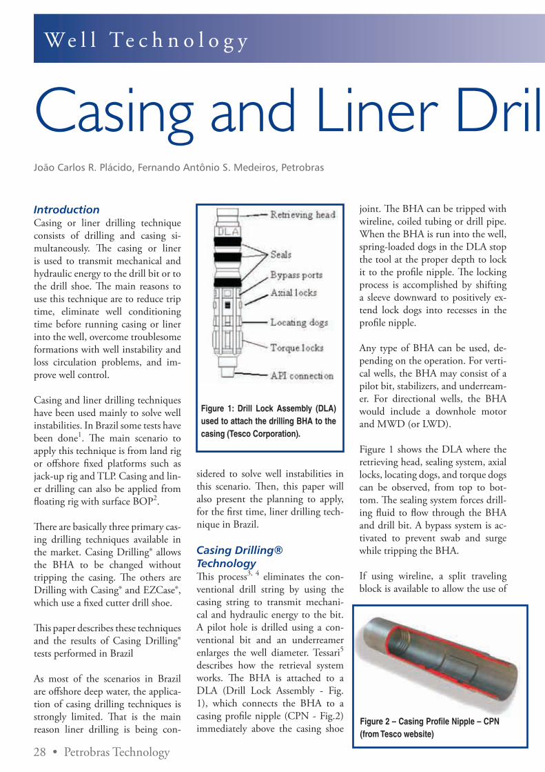
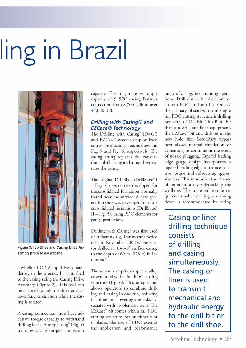
Casing Drilling® TechnologyThis process3, 4 eliminates the con-ventional drill string by using the casing string to transmit mechani-cal and hydraulic energy to the bit. A pilot hole is drilled using a con-ventional bit and an underreamer enlarges the well diameter. Tessari5 describes how the retrieval system works. The BHA is attached to a DLA (Drill Lock Assembly - Fig. 1), which connects the BHA to a casing profile nipple (CPN - Fig.2) immediately above the casing shoe
Figure 1: Drill Lock Assembly (DLA) used to attach the drilling BHA to the casing (Tesco Corporation).
joint. The BHA can be tripped with wireline, coiled tubing or drill pipe. When the BHA is run into the well, spring-loaded dogs in the DLA stop the tool at the proper depth to lock it to the profile nipple. The locking process is accomplished by shifting a sleeve downward to positively ex-tend lock dogs into recesses in the profile nipple.
Any type of BHA can be used, de-pending on the operation. For verti-cal wells, the BHA may consist of a pilot bit, stabilizers, and underream-er. For directional wells, the BHA would include a downhole motor and MWD (or LWD).
Figure 1 shows the DLA where the retrieving head, sealing system, axial locks, locating dogs, and torque dogs can be observed, from top to bot-tom. The sealing system forces drill-ing fluid to flow through the BHA and drill bit. A bypass system is ac-tivated to prevent swab and surge while tripping the BHA.
If using wireline, a split traveling block is available to allow the use of
Figure 2 – Casing Profile Nipple – CPN (from Tesco website)
We l l Te c h n o l o g y
Casing and Liner Drilling in BrazilJoão Carlos R. Plácido, Fernando Antônio S. Medeiros, Petrobras
Petrobras Technology • 29
Casing and Liner Drilling in Brazil
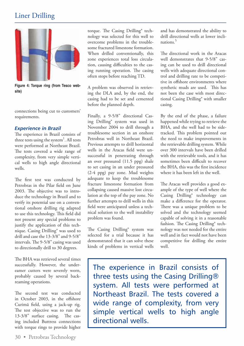
a wireline BOP. A top drive is man-datory in the process. It is attached to the casing using the Casing Drive Assembly (Figure 2). This tool can be adapted to any top drive and al-lows fluid circulation while the cas-ing is rotated.
A casing connection must have ad-equate torque capacity to withstand drilling loads. A torque ring6 (Fig. 4) increases casing torque connection
Figure 3: Top Drive and Casing Drive As-sembly (from Tesco website)
capacity. This ring increases torque capacity of 9 5/8” casing Buttress connection from 8,700 ft-lb to over 44,000 ft-lb.
Drilling with Casing® and EZCase® TechnologyThe Drilling with Casing® (DwC®) and EZCase® systems employ fixed cutters on a casing shoe, as shown in Fig. 5 and Fig. 6, respectively. The casing string replaces the conven-tional drill string and a top drive ro-tates the casing.
The original DrillShoe (DrillShoe® I – Fig. 5) uses cutters developed for unconsolidated formation normally found near the surface. A new gen-eration shoe was developed for more consolidated formations (DrillShoe® II – Fig. 5), using PDC elements for gauge protection.
Drilling with Casing® was first used on a floating rig, Transocean’s Sedco 601, in November 2002 where San-tos drilled in 13-3/8” surface casing to the depth of 69 m (228 ft) in In-donesia2.
The system comprises a special alloy crown fitted with a full PDC cutting structure (Fig. 6). This unique tool allows operators to combine drill-ing and casing in one run, reducing flat time and lowering the risks as-sociated with problematic wells. The EZCase® bit comes with a full PDC cutting structure. Set on either 4 or 6 blades, the use of PDC extends the application and performance
range of casing/liner running opera-tions. Drill out with roller cone or custom PDC drill out bit. One of the primary obstacles to utilizing a full PDC cutting structure is drilling out with a PDC bit. This PDC bit that can drill out float equipment, the EZCase® bit and drill on in the new hole size. Secondary bypass port allows normal circulation or cementing to continue in the event of nozzle plugging. Tapered leading edge gauge design incorporates a tapered leading edge to reduce reac-tive torque and sidecutting aggres-siveness. This minimizes the chance of unintentionally sidetracking the wellbore. The increased torque re-quirement when drilling or reaming down is accommodated by casing
Casing or liner drilling technique consists of drilling and casing simultaneously. The casing or liner is used to transmit mechanical and hydraulic energy to the drill bit or to the drill shoe.
30 • Petrobras Technology
connections being cut to customers’ requirements.
Experience in BrazilThe experience in Brazil consists of three tests using the system1. All tests were performed at Northeast Brazil. The tests covered a wide range of complexity, from very simple verti-cal wells to high angle directional wells.
The first test was conducted by Petrobras in the Pilar field on June 2003. The objective was to intro-duce the technology in Brazil and to verify its potential use on a conven-tional onshore drilling rig adapted to use this technology. This field did not present any special problems to justify the application of this tech-nique. Casing Drilling® was used to drill and case the 13-3/8” and 9-5/8” intervals. The 9-5/8” casing was used to directionally drill to 30 degrees.
The BHA was retrieved several times successfully. However, the under-eamer cutters were severely worn, probably caused by several back-reaming operations.
The second test was conducted in October 2003, in the offshore Curimã field, using a jack-up rig. The test objective was to run the 13-3/8” surface casing. The cas-ing included Buttress connections with torque rings to provide higher
torque. The Casing Drilling® tech-nology was selected for this well to overcome problems in the trouble-some fractured limestone formation. When drilled conventionally, this zone experiences total loss circula-tion, causing difficulties to the cas-ing running operation. The casing often stops before reaching TD.
A problem was observed in retriev-ing the DLA and, by the end, the casing had to be set and cemented before the planned depth.
Finally, a 9-5/8” directional Cas-ing Drilling® system was used in November 2004 to drill through a troublesome section in an onshore Petrobras well in Northeast Brazil. Previous attempts to drill horizontal wells in the Aracas field were un-successful in penetrating through an over pressured (11.5 ppg) shale to set casing in an under pressured (2-4 ppg) pay zone. Mud weights adequate to keep the troublesome fracture limestone formation from collapsing caused massive lost circu-lation at the top of the pay zone. No further attempts to drill wells in this field were anticipated unless a tech-nical solution to the well instability problem was found.
The Casing Drilling® system was selected for a trial because it has demonstrated that it can solve these kinds of problems in vertical wells
and has demonstrated the ability to drill directional wells at lower incli-nations.5
The directional work in the Aracas well demonstrates that 9-5/8” cas-ing can be used to drill directional wells with adequate directional con-trol and drilling rate to be competi-tive in offshore environments where synthetic muds are used. This has not been the case with most direc-tional Casing Drilling® with smaller casing.
By the end of the phase, a failure happened while trying to retrieve the BHA, and the well had to be side-tracked. This problem pointed out the need to make improvements in the retrievable drilling system. While over 300 intervals have been drilled with the retrievable tools, and it has sometimes been difficult to recover the BHA, this was the first incidence where it has been left in the well.
The Aracas well provides a good ex-ample of the type of well where the Casing Drilling® technology can make a difference for the operator. There was a unique problem to be solved and the technology seemed capable of solving it in a reasonable fashion. The Casing Drilling® tech-nology was not needed for the entire well and in fact would not have been competitive for drilling the entire well.
Figure 4: Torque ring (from Tesco web-site)
The experience in Brazil consists of three tests using the Casing Drilling® system. All tests were performed at Northeast Brazil. The tests covered a wide range of complexity, from very simple vertical wells to high angle directional wells.
Liner Drilling
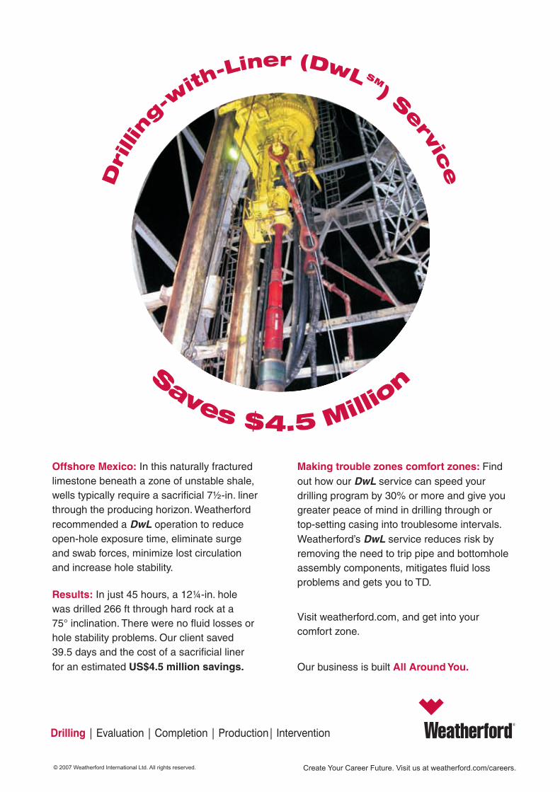
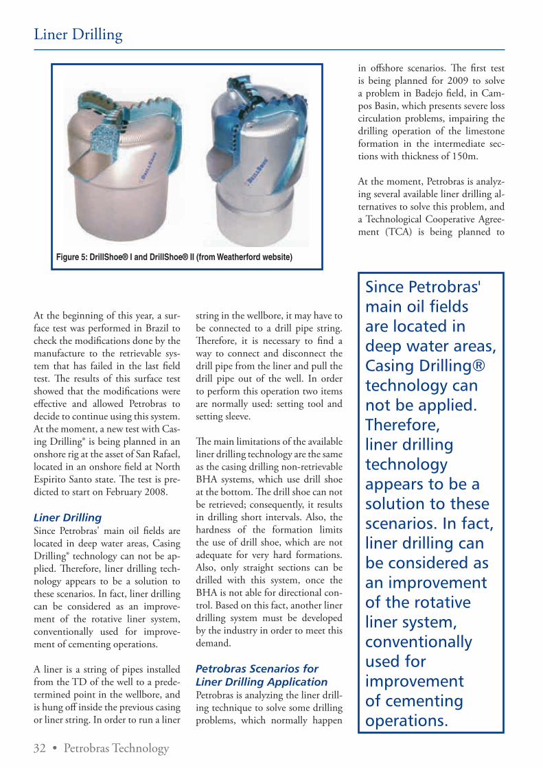
32 • Petrobras Technology
Figure 5: DrillShoe® I and DrillShoe® II (from Weatherford website)
Liner Drilling
At the beginning of this year, a sur-face test was performed in Brazil to check the modifications done by the manufacture to the retrievable sys-tem that has failed in the last field test. The results of this surface test showed that the modifications were effective and allowed Petrobras to decide to continue using this system. At the moment, a new test with Cas-ing Drilling® is being planned in an onshore rig at the asset of San Rafael, located in an onshore field at North Espirito Santo state. The test is pre-dicted to start on February 2008.
Liner DrillingSince Petrobras' main oil fields are located in deep water areas, Casing Drilling® technology can not be ap-plied. Therefore, liner drilling tech-nology appears to be a solution to these scenarios. In fact, liner drilling can be considered as an improve-ment of the rotative liner system, conventionally used for improve-ment of cementing operations.
A liner is a string of pipes installed from the TD of the well to a prede-termined point in the wellbore, and is hung off inside the previous casing or liner string. In order to run a liner
string in the wellbore, it may have to be connected to a drill pipe string. Therefore, it is necessary to find a way to connect and disconnect the drill pipe from the liner and pull the drill pipe out of the well. In order to perform this operation two items are normally used: setting tool and setting sleeve.
The main limitations of the available liner drilling technology are the same as the casing drilling non-retrievable BHA systems, which use drill shoe at the bottom. The drill shoe can not be retrieved; consequently, it results in drilling short intervals. Also, the hardness of the formation limits the use of drill shoe, which are not adequate for very hard formations. Also, only straight sections can be drilled with this system, once the BHA is not able for directional con-trol. Based on this fact, another liner drilling system must be developed by the industry in order to meet this demand.
Petrobras Scenarios for Liner Drilling ApplicationPetrobras is analyzing the liner drill-ing technique to solve some drilling problems, which normally happen
in offshore scenarios. The first test is being planned for 2009 to solve a problem in Badejo field, in Cam-pos Basin, which presents severe loss circulation problems, impairing the drilling operation of the limestone formation in the intermediate sec-tions with thickness of 150m.
At the moment, Petrobras is analyz-ing several available liner drilling al-ternatives to solve this problem, and a Technological Cooperative Agree-ment (TCA) is being planned to
Since Petrobras' main oil fields are located in deep water areas, Casing Drilling® technology can not be applied. Therefore, liner drilling technology appears to be a solution to these scenarios. In fact, liner drilling can be considered as an improvement of the rotative liner system, conventionally used for improvement of cementing operations.
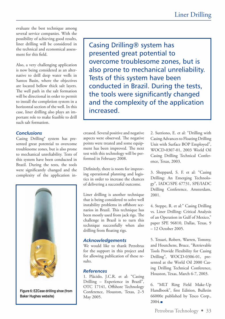
Petrobras Technology • 33
Liner Drilling
Figure 6: EZCase drilling shoe (from Baker Hughes website)
evaluate the best technique among several service companies. With the possibility of achieving good results, liner drilling will be considered in the technical and economical assess-ment for this field.
Also, a very challenging application is now being considered as an alter-native to drill deep water wells in Santos Basin, where the objectives are located bellow thick salt layers. The well path in the salt formation will be directional in order to permit to install the completion system in a horizontal section of the well. In this case, liner drilling also plays an im-portant role to make feasible to drill such salt formation.
ConclusionsCasing Drilling® system has pre-sented great potential to overcome troublesome zones, but is also prone to mechanical unreliability. Tests of this system have been conducted in Brazil. During the tests, the tools were significantly changed and the complexity of the application in-
creased. Several positive and negative aspects were observed. The negative points were treated and some equip-ment has been improved. The next test with this technology will be per-formed in February 2008.
Definitely, there is room for improv-ing operational planning and logis-tics in order to increase the chances of delivering a successful outcome.
Liner drilling is another technique that is being considered to solve well instability problems in offshore sce-narios in Brazil. This technique has been mostly used from jack rigs. The challenge in Brazil is to turn this technique successfully when also drilling from floating rigs.
AcknowledgementsWe would like to thank Petrobras for the support in this project and for allowing publication of these re-sults.
References1. Plácido, J.C.R. et al: “Casing Drilling – Experience in Brazil”, OTC 17141, Offshore Technology Conference, Houston, Texas, 2–5 May 2005.
2. Sutriono, E. et al: “Drilling with Casing Advances to Floating Drilling Unit with Surface BOP Employed”, WOCD-0307-01, 2003 World Oil Casing Drilling Technical Confer-ence, Texas, 2003.
3. Sheppard, S. F. et al: “Casing Drilling: An Emerging Technolo-gy”, IADC/SPE 67731, SPE/IADC Drilling Conference, Amsterdam, 2001.
4. Steppe, R. et al:” Casing Drilling vs. Liner Drilling: Critical Analysis of an Operation in Gulf of Mexico,” paper SPE 96810, Dallas, Texas, 9 – 12 October 2005.
5. Tessari, Robert, Warren, Tommy, and Houtchens, Bruce, “Retrievable Tools Provide Flexibility for Casing Drilling”, WOCD-0306-01, pre-sented at the World Oil 2000 Cas-ing Drilling Technical Conference, Houston, Texas, March 6-7, 2003.
6. “MLT Ring Field Make-Up Handbook”, first Edition, Bulletin 66000e published by Tesco Corp., 2004.
Casing Drilling® system has presented great potential to overcome troublesome zones, but is also prone to mechanical unreliability. Tests of this system have been conducted in Brazil. During the tests, the tools were significantly changed and the complexity of the application increased.
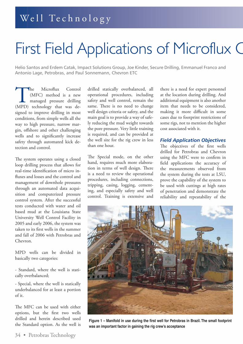
34 • Petrobras Technology
We l l Te c h n o l o g y
First Field Applications of Microflux Control Show Very Positive ResultsHelio Santos and Erdem Catak, Impact Solutions Group, Joe Kinder, Secure Drilling, Emmanuel Franco and Antonio Lage, Petrobras, and Paul Sonnemann, Chevron ETC
The Microflux Control (MFC) method is a new managed pressure drilling
(MPD) technology that was de-signed to improve drilling in most conditions, from simple wells all the way to high pressure, narrow mar-gin, offshore and other challenging wells and to significantly increase safety through automated kick de-tection and control.
The system operates using a closed loop drilling process that allows for real-time identification of micro in-fluxes and losses and the control and management of downhole pressures through an automated data acqui-sition and computerized pressure control system. After the successful tests conducted with water and oil based mud at the Louisiana State University Well Control Facility in 2005 and early 2006, the system was taken to its first wells in the summer and fall of 2006 with Petrobras and Chevron.
MPD wells can be divided in basically two categories:
- Standard, where the well is stati-cally overbalanced;
- Special, where the well is statically underbalanced for at least a portion of it.
The MFC can be used with either options, but the first two wells drilled and herein described used the Standard option. As the well is
drilled statically overbalanced, all operational procedures, including safety and well control, remain the same. There is no need to change well design criteria or safety, and the main goal is to provide a way of safe-ly reducing the mud weight towards the pore pressure. Very little training is required, and can be provided at the well site for the rig crew in less than one hour.
The Special mode, on the other hand, requires much more elabora-tion in terms of well design. There is a need to review the operational procedures, including connections, tripping, casing, logging, cement-ing, and especially safety and well control. Training is extensive and
there is a need for expert personnel at the location during drilling. And additional equipment is also another item that needs to be considered, making it more difficult in some cases due to footprint restrictions of some rigs, not to mention the higher cost associated with it.
Field Application ObjectivesThe objectives of the first wells drilled for Petrobras and Chevron using the MFC were to confirm in field applications the accuracy of the measurements observed from the system during the tests at LSU, prove the capability of the system to be used with cuttings at high rates of penetration and demonstrate the reliability and repeatability of the
Figure 1 – Manifold in use during the first well for Petrobras in Brazil. The small footprint was an important factor in gaining the rig crew’s acceptance
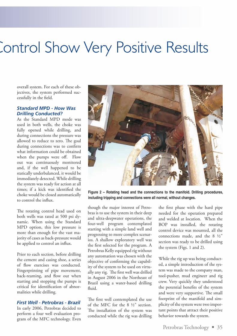
Petrobras Technology • 35
First Field Applications of Microflux Control Show Very Positive Results
overall system. For each of these ob-jectives, the system performed suc-cessfully in the field.
Standard MPD - How Was Drilling Conducted?As the Standard MPD mode was used in both wells, the choke was fully opened while drilling, and during connections the pressure was allowed to reduce to zero. The goal during connections was to confirm what information could be obtained when the pumps were off. Flow out was continuously monitored and, if the well happened to be statically underbalanced, it would be immediately detected. While drilling the system was ready for action at all times; if a kick was identified the choke would be closed automatically to control the influx.
The rotating control head used on both wells was rated at 500 psi dy-namic. When using the Standard MPD option, this low pressure is more than enough for the vast ma-jority of cases as back-pressure would be applied to control an influx.
Prior to each section, before drilling the cement and casing shoe, a series of flow exercises was conducted. Fingerprinting of pipe movement, back-reaming, and flow out when starting and stopping the pumps is critical for identification of abnor-malities while drilling.
First Well - Petrobras - BrazilIn early 2006, Petrobras decided to perform a four well evaluation pro-gram of the MFC technology. Even
though the major interest of Petro-bras is to use the system in their deep and ultra-deepwater operations, the four-well program contemplated starting with a simple land well and progressing to more complex scenar-ios. A shallow exploratory well was the first selected for the program. A Petrobras Kelly equipped rig without any automation was chosen with the objective of confirming the capabil-ity of the system to be used on virtu-ally any rig. The first well was drilled in August 2006 in the Northeast of Brazil using a water-based drilling fluid.
The first well contemplated the use of the MFC for the 8 ½” section. The installation of the system was conducted while the rig was drilling
the first phase with the hard pipe needed for the operation prepared and welded at location. When the BOP was installed, the rotating control device was mounted, all the connections made, and the 8 ½” section was ready to be drilled using the system (Figs. 1 and 2).
While the rig up was being conduct-ed, a simple introduction of the sys-tem was made to the company man, tool-pusher, mud engineer and rig crew. Very quickly they understood the potential benefits of the system and were very supportive. The small footprint of the manifold and sim-plicity of the system were two impor-tant points that attract their positive behavior towards the system.
Figure 2 – Rotating head and the connections to the manifold. Drilling procedures, including tripping and connections were all normal, without changes.
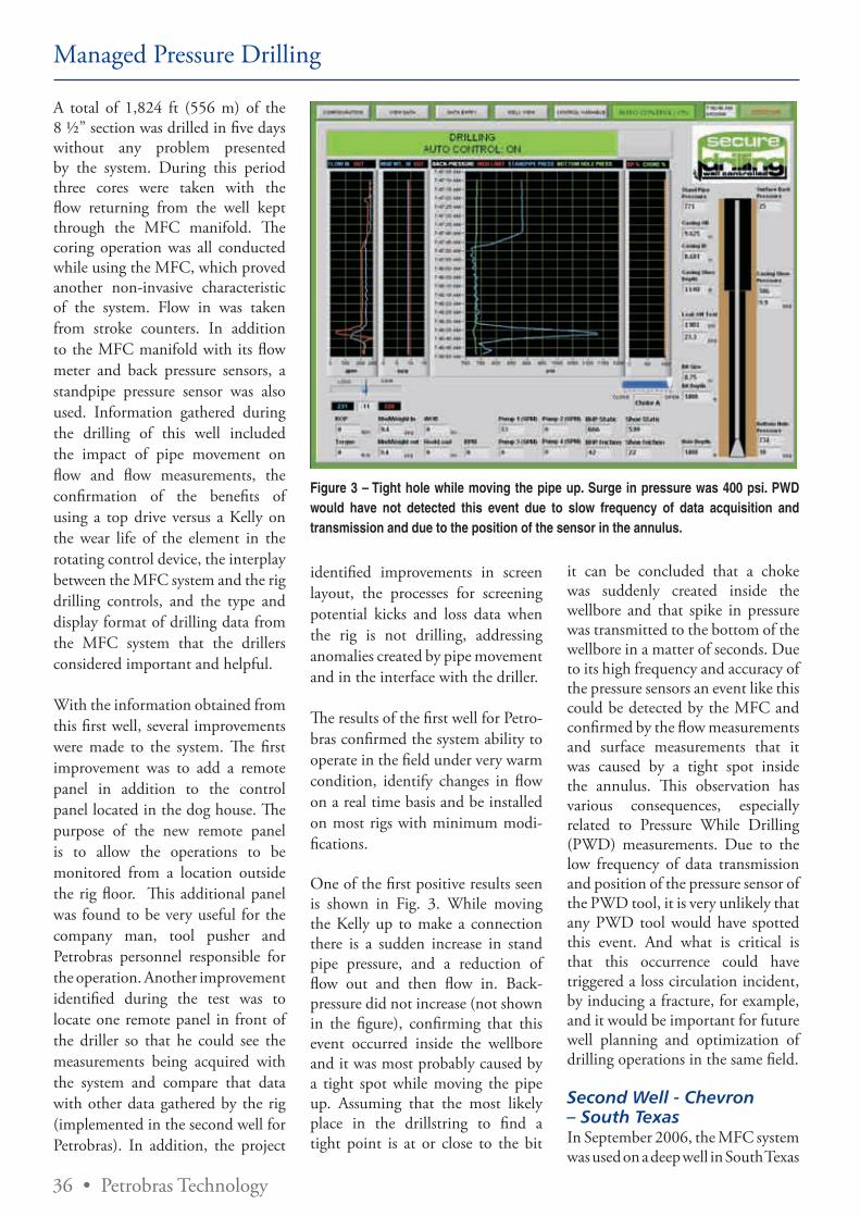
36 • Petrobras Technology
Managed Pressure Drilling
A total of 1,824 ft (556 m) of the 8 ½” section was drilled in five days without any problem presented by the system. During this period three cores were taken with the flow returning from the well kept through the MFC manifold. The coring operation was all conducted while using the MFC, which proved another non-invasive characteristic of the system. Flow in was taken from stroke counters. In addition to the MFC manifold with its flow meter and back pressure sensors, a standpipe pressure sensor was also used. Information gathered during the drilling of this well included the impact of pipe movement on flow and flow measurements, the confirmation of the benefits of using a top drive versus a Kelly on the wear life of the element in the rotating control device, the interplay between the MFC system and the rig drilling controls, and the type and display format of drilling data from the MFC system that the drillers considered important and helpful.
With the information obtained from this first well, several improvements were made to the system. The first improvement was to add a remote panel in addition to the control panel located in the dog house. The purpose of the new remote panel is to allow the operations to be monitored from a location outside the rig floor. This additional panel was found to be very useful for the company man, tool pusher and Petrobras personnel responsible for the operation. Another improvement identified during the test was to locate one remote panel in front of the driller so that he could see the measurements being acquired with the system and compare that data with other data gathered by the rig (implemented in the second well for Petrobras). In addition, the project
identified improvements in screen layout, the processes for screening potential kicks and loss data when the rig is not drilling, addressing anomalies created by pipe movement and in the interface with the driller.
The results of the first well for Petro-bras confirmed the system ability to operate in the field under very warm condition, identify changes in flow on a real time basis and be installed on most rigs with minimum modi-fications.
One of the first positive results seen is shown in Fig. 3. While moving the Kelly up to make a connection there is a sudden increase in stand pipe pressure, and a reduction of flow out and then flow in. Back-pressure did not increase (not shown in the figure), confirming that this event occurred inside the wellbore and it was most probably caused by a tight spot while moving the pipe up. Assuming that the most likely place in the drillstring to find a tight point is at or close to the bit
Figure 3 – Tight hole while moving the pipe up. Surge in pressure was 400 psi. PWD would have not detected this event due to slow frequency of data acquisition and transmission and due to the position of the sensor in the annulus.
it can be concluded that a choke was suddenly created inside the wellbore and that spike in pressure was transmitted to the bottom of the wellbore in a matter of seconds. Due to its high frequency and accuracy of the pressure sensors an event like this could be detected by the MFC and confirmed by the flow measurements and surface measurements that it was caused by a tight spot inside the annulus. This observation has various consequences, especially related to Pressure While Drilling (PWD) measurements. Due to the low frequency of data transmission and position of the pressure sensor of the PWD tool, it is very unlikely that any PWD tool would have spotted this event. And what is critical is that this occurrence could have triggered a loss circulation incident, by inducing a fracture, for example, and it would be important for future well planning and optimization of drilling operations in the same field.
Second Well - Chevron – South TexasIn September 2006, the MFC system was used on a deep well in South Texas
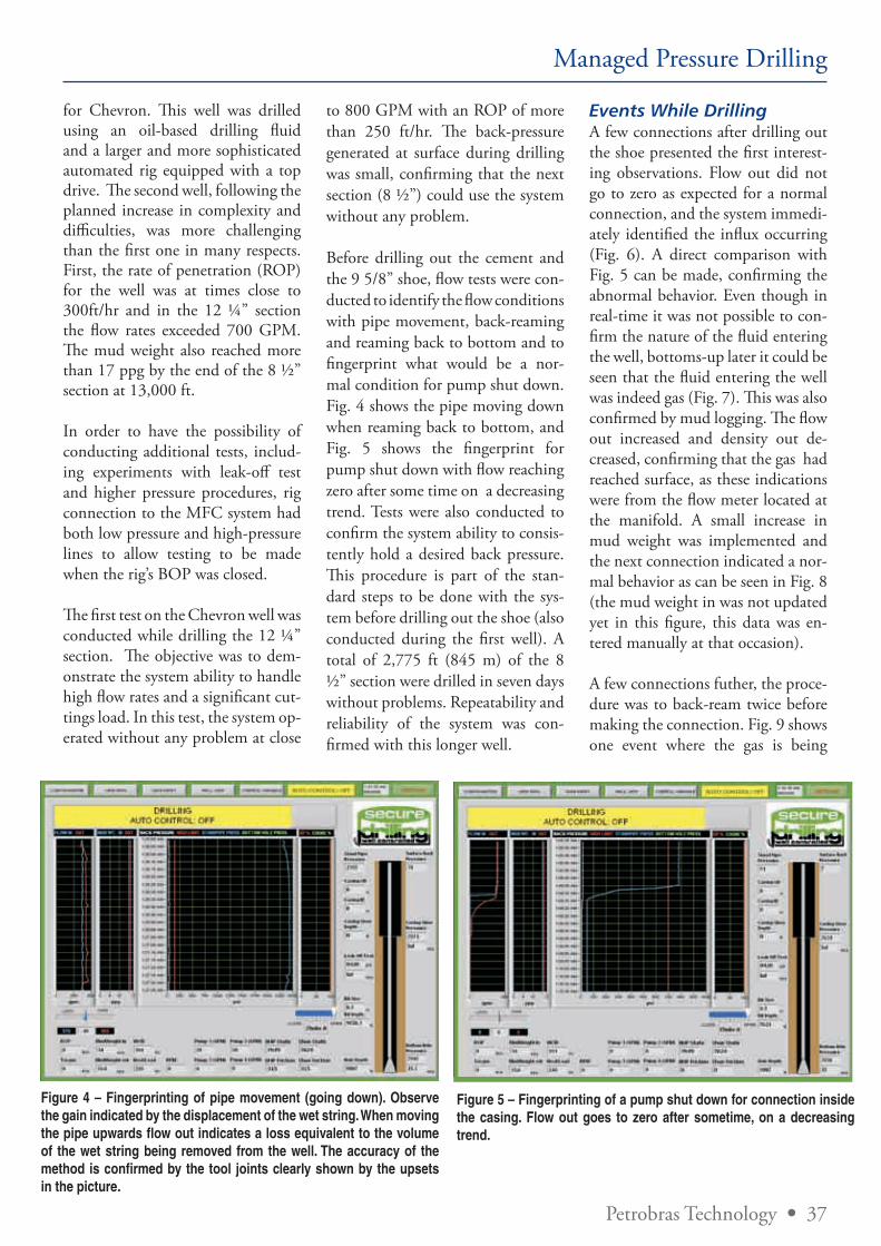
Petrobras Technology • 37
Managed Pressure Drilling
for Chevron. This well was drilled using an oil-based drilling fluid and a larger and more sophisticated automated rig equipped with a top drive. The second well, following the planned increase in complexity and difficulties, was more challenging than the first one in many respects. First, the rate of penetration (ROP) for the well was at times close to 300ft/hr and in the 12 ¼” section the flow rates exceeded 700 GPM. The mud weight also reached more than 17 ppg by the end of the 8 ½” section at 13,000 ft.
In order to have the possibility of conducting additional tests, includ-ing experiments with leak-off test and higher pressure procedures, rig connection to the MFC system had both low pressure and high-pressure lines to allow testing to be made when the rig’s BOP was closed.
The first test on the Chevron well was conducted while drilling the 12 ¼” section. The objective was to dem-onstrate the system ability to handle high flow rates and a significant cut-tings load. In this test, the system op-erated without any problem at close
Figure 4 – Fingerprinting of pipe movement (going down). Observe the gain indicated by the displacement of the wet string. When moving the pipe upwards flow out indicates a loss equivalent to the volume of the wet string being removed from the well. The accuracy of the method is confirmed by the tool joints clearly shown by the upsets in the picture.
Figure 5 – Fingerprinting of a pump shut down for connection inside the casing. Flow out goes to zero after sometime, on a decreasing trend.
to 800 GPM with an ROP of more than 250 ft/hr. The back-pressure generated at surface during drilling was small, confirming that the next section (8 ½”) could use the system without any problem.
Before drilling out the cement and the 9 5/8” shoe, flow tests were con-ducted to identify the flow conditions with pipe movement, back-reaming and reaming back to bottom and to fingerprint what would be a nor-mal condition for pump shut down. Fig. 4 shows the pipe moving down when reaming back to bottom, and Fig. 5 shows the fingerprint for pump shut down with flow reaching zero after some time on a decreasing trend. Tests were also conducted to confirm the system ability to consis-tently hold a desired back pressure. This procedure is part of the stan-dard steps to be done with the sys-tem before drilling out the shoe (also conducted during the first well). A total of 2,775 ft (845 m) of the 8 ½” section were drilled in seven days without problems. Repeatability and reliability of the system was con-firmed with this longer well.
Events While DrillingA few connections after drilling out the shoe presented the first interest-ing observations. Flow out did not go to zero as expected for a normal connection, and the system immedi-ately identified the influx occurring (Fig. 6). A direct comparison with Fig. 5 can be made, confirming the abnormal behavior. Even though in real-time it was not possible to con-firm the nature of the fluid entering the well, bottoms-up later it could be seen that the fluid entering the well was indeed gas (Fig. 7). This was also confirmed by mud logging. The flow out increased and density out de-creased, confirming that the gas had reached surface, as these indications were from the flow meter located at the manifold. A small increase in mud weight was implemented and the next connection indicated a nor-mal behavior as can be seen in Fig. 8 (the mud weight in was not updated yet in this figure, this data was en-tered manually at that occasion).
A few connections futher, the proce-dure was to back-ream twice before making the connection. Fig. 9 shows one event where the gas is being
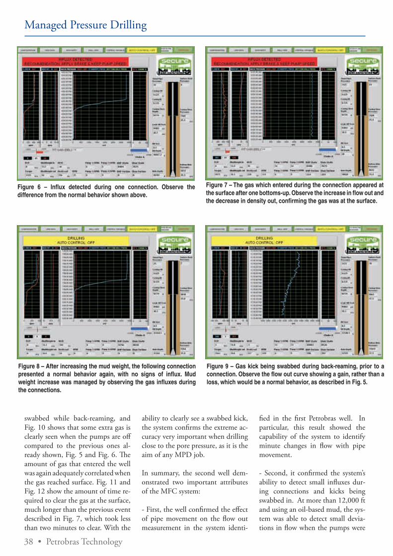
38 • Petrobras Technology
Managed Pressure Drilling
swabbed while back-reaming, and Fig. 10 shows that some extra gas is clearly seen when the pumps are off compared to the previous ones al-ready shown, Fig. 5 and Fig. 6. The amount of gas that entered the well was again adequately correlated when the gas reached surface. Fig. 11 and Fig. 12 show the amount of time re-quired to clear the gas at the surface, much longer than the previous event described in Fig. 7, which took less than two minutes to clear. With the
Figure 6 – Influx detected during one connection. Observe the difference from the normal behavior shown above.
Figure 7 – The gas which entered during the connection appeared at the surface after one bottoms-up. Observe the increase in flow out and the decrease in density out, confirming the gas was at the surface.
Figure 8 – After increasing the mud weight, the following connection presented a normal behavior again, with no signs of influx. Mud weight increase was managed by observing the gas influxes during the connections.
Figure 9 – Gas kick being swabbed during back-reaming, prior to a connection. Observe the flow out curve showing a gain, rather than a loss, which would be a normal behavior, as described in Fig. 5.
ability to clearly see a swabbed kick, the system confirms the extreme ac-curacy very important when drilling close to the pore pressure, as it is the aim of any MPD job.
In summary, the second well dem-onstrated two important attributes of the MFC system:
- First, the well confirmed the effect of pipe movement on the flow out measurement in the system identi-
fied in the first Petrobras well. In particular, this result showed the capability of the system to identify minute changes in flow with pipe movement.
- Second, it confirmed the system’s ability to detect small influxes dur-ing connections and kicks being swabbed in. At more than 12,000 ft and using an oil-based mud, the sys-tem was able to detect small devia-tions in flow when the pumps were
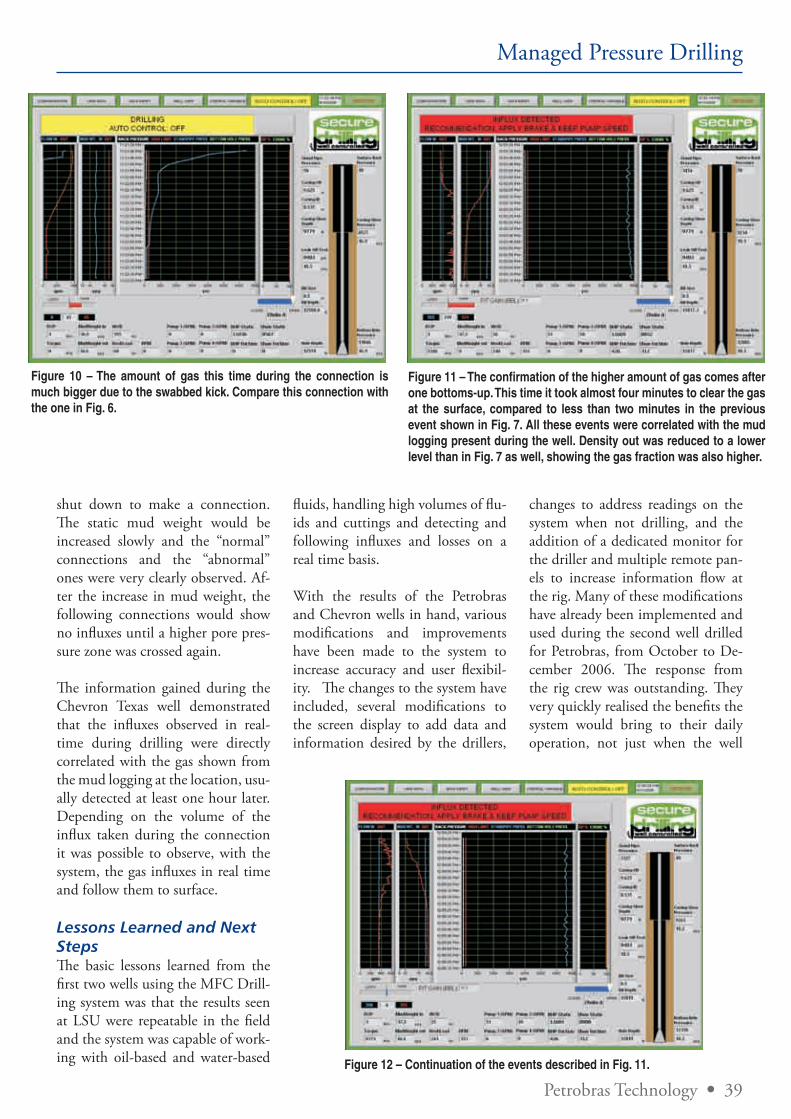
Petrobras Technology • 39
Managed Pressure Drilling
Figure 10 – The amount of gas this time during the connection is much bigger due to the swabbed kick. Compare this connection with the one in Fig. 6.
Figure 11 – The confirmation of the higher amount of gas comes after one bottoms-up. This time it took almost four minutes to clear the gas at the surface, compared to less than two minutes in the previous event shown in Fig. 7. All these events were correlated with the mud logging present during the well. Density out was reduced to a lower level than in Fig. 7 as well, showing the gas fraction was also higher.
Figure 12 – Continuation of the events described in Fig. 11.
shut down to make a connection. The static mud weight would be increased slowly and the “normal” connections and the “abnormal” ones were very clearly observed. Af-ter the increase in mud weight, the following connections would show no influxes until a higher pore pres-sure zone was crossed again.
The information gained during the Chevron Texas well demonstrated that the influxes observed in real-time during drilling were directly correlated with the gas shown from the mud logging at the location, usu-ally detected at least one hour later. Depending on the volume of the influx taken during the connection it was possible to observe, with the system, the gas influxes in real time and follow them to surface.
Lessons Learned and Next StepsThe basic lessons learned from the first two wells using the MFC Drill-ing system was that the results seen at LSU were repeatable in the field and the system was capable of work-ing with oil-based and water-based
fluids, handling high volumes of flu-ids and cuttings and detecting and following influxes and losses on a real time basis.
With the results of the Petrobras and Chevron wells in hand, various modifications and improvements have been made to the system to increase accuracy and user flexibil-ity. The changes to the system have included, several modifications to the screen display to add data and information desired by the drillers,
changes to address readings on the system when not drilling, and the addition of a dedicated monitor for the driller and multiple remote pan-els to increase information flow at the rig. Many of these modifications have already been implemented and used during the second well drilled for Petrobras, from October to De-cember 2006. The response from the rig crew was outstanding. They very quickly realised the benefits the system would bring to their daily operation, not just when the well
40 • Petrobras Technology
Managed Pressure Drilling
is a diffi cult one. Th e simplicity of the system, small footprint, and by keeping all operational procedures the same as conventional drilling made the rig crew accept the system extremely well.
Another well using the Standard mode and another using the Spe-cial MPD mode have already been drilled to date. Results were re-peatable and new lessons were also learned. Results from these wells will be presented in future publications.
A series of new wells will be drilled in the coming months, including both modes, Standard and Special. Combination of the MFC with other emerging technologies is also planned for the near future, in an at-tempt to make the most of the col-lection of MPD tools available to the drilling engineer.
ConclusionsDrilling the fi rst wells with the MFC provided the following conclusions:
- Th e system proved to be very ac-curate, with the confi rmation of the possibility of “seeing” the tool joints passing through the rotating control head while moving the pipe up or down;
- Th e system confi rmed all the ca-pabilities shown during the tests at LSU, this time with cuttings and pipe movement;
- Th e chokes and fl ow meter did not have any plugging problems, even drilling the 12 ¼” section with al-most 800 GPM and close to 300 ft/hr of ROP;
- Th e system’s electronics were tested under very warm conditions, and they did not present a problem. Th e system confi rmed it can work under fi eld conditions without problems;
- All the infl uxes observed during connections were detected in real-time by the system. Th e infl uxes were confi rmed by the MFC when reaching surface, with the combina-tion of higher fl ow rate and reduc-tion of density observed from the fl ow meter;
- All the infl uxes observed by the sys-tem in real-time during connections were only detected by the mud log-ging one bottoms-up later;
- Surface data collected from the system provides a more realistic pic-ture of the downhole events than the ones provided by PWD, due to the high frequency and accuracy;
- Another interesting event detect-ed by the system was a kick being swabbed in. Th is confi rms the mud weight is very close to the pore pres-sure, one of the goals of any MPD job. Th e events detected by the MFC should be used to manage the mud weight increase along the well, to maintain the mud weight as close as possible to the pore pressure curve;
- Th e small footprint and simplicity of the system were two of the main points considered by the rig crew as very positive;
- It was confi rmed that the Standard MPD mode requires very little train-ing and all operational procedures, including drilling, tripping, con-nection, casing, logging, cementing, safety and well control do not need to change from the conventional ones. Well design does not need any change either;
- Several suggestions and feed-back were collected from the rig personnel at location from both wells. Some of them have been already implemented for the second well drilled for Petro-bras, and were very well received by the rig crew and company man.
References
1. Santos, H, Reid, P., Leuchten-berg, C, Jones, C, Lage, A., Nogueira, E. and Kozicz, J.: “Micro-Flux Control Method Combined with Surface BOP Creates Enabling Opportunity for Deepwater and Off shore Drilling,” paper OTC 17451, presented at the 2005 Off shore Technology Conference, Hous-ton, TX, 2–5 May 2005.
2. Santos, H, Leuchtenberg, C, Reid, P. and Lage, A.: “Open-ing New Exploration Frontiers with the Micro-Flux Control Method for Well Design,” pa-per OTC 16622, presented at the 2004 Off shore Technology Conference, Houston, Texas, 3–6 May 2004.
3. Santos, H., Leuchtenberg, C, and Shayegi, S.: “Micro-Flux Control: Th e Next Gen-eration in Drilling,” paper SPE 81183, presented at the SPE Latin American and Caribbean Petroleum Engineering Con-ference, Port-of-Spain, Trini-dad, West Indies, 27-30 April 2003.
4. Catak, E. and Santos, H.: “Secure Drilling System Op-erational Manual, version 1.0,” Houston, TX, 30 April 2006.
5. Santos, H., Catak, E., Kind-er, J. & Sonnemann, P.: “Kick Detection and Control in Oil-based Mud: Real Well Test Re-sults Using Micro-Flux Control Equipment”, paper SPE/IADC 105454, presented at the 2007 SPE/IADC Drilling Confer-ence held in Amsterdam, Th e Netherlands, 20–22 February 2007.
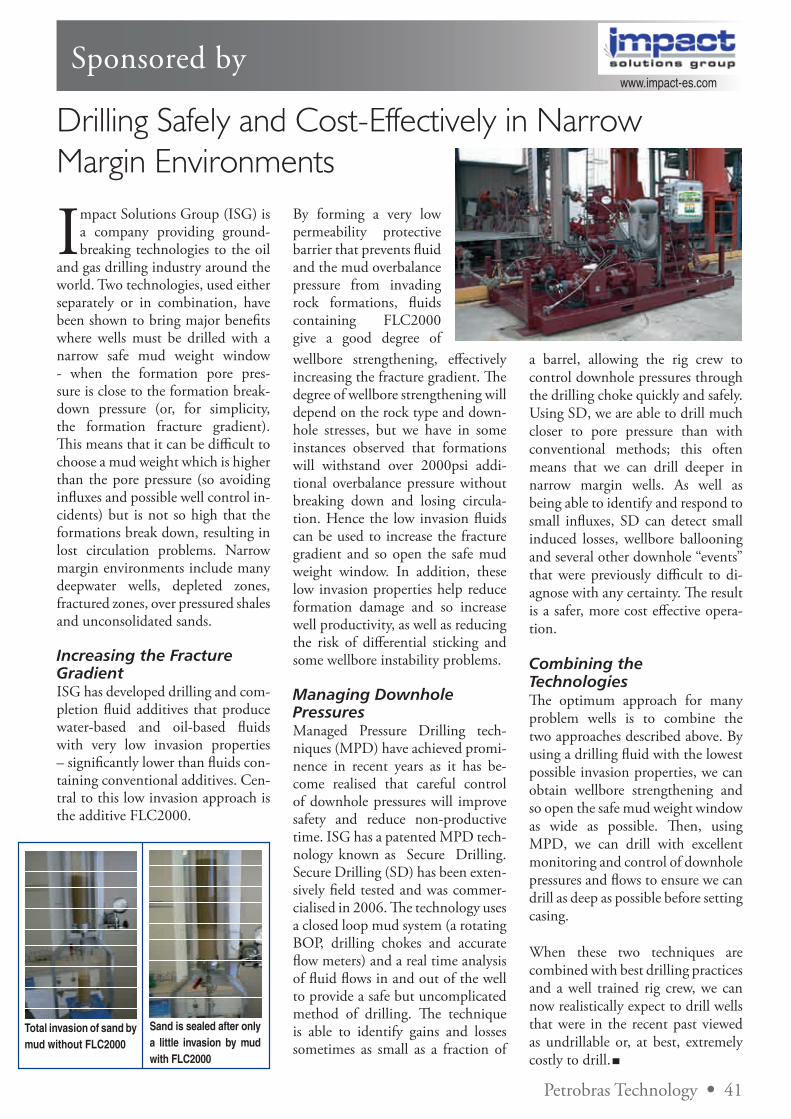
Sponsored by
Drilling Safely and Cost-Effectively in Narrow Margin Environments
Impact Solutions Group (ISG) is a company providing ground-breaking technologies to the oil
and gas drilling industry around the world. Two technologies, used either separately or in combination, have been shown to bring major benefits where wells must be drilled with a narrow safe mud weight window - when the formation pore pres-sure is close to the formation break-down pressure (or, for simplicity, the formation fracture gradient). This means that it can be difficult to choose a mud weight which is higher than the pore pressure (so avoiding influxes and possible well control in-cidents) but is not so high that the formations break down, resulting in lost circulation problems. Narrow margin environments include many deepwater wells, depleted zones, fractured zones, over pressured shales and unconsolidated sands.
Increasing the Fracture GradientISG has developed drilling and com-pletion fluid additives that produce water-based and oil-based fluids with very low invasion properties – significantly lower than fluids con-taining conventional additives. Cen-tral to this low invasion approach is the additive FLC2000.
By forming a very low permeability protective barrier that prevents fluid and the mud overbalance pressure from invading rock formations, fluids containing FLC2000 give a good degree of
a barrel, allowing the rig crew to control downhole pressures through the drilling choke quickly and safely. Using SD, we are able to drill much closer to pore pressure than with conventional methods; this often means that we can drill deeper in narrow margin wells. As well as being able to identify and respond to small influxes, SD can detect small induced losses, wellbore ballooning and several other downhole “events” that were previously difficult to di-agnose with any certainty. The result is a safer, more cost effective opera-tion.
Combining the TechnologiesThe optimum approach for many problem wells is to combine the two approaches described above. By using a drilling fluid with the lowest possible invasion properties, we can obtain wellbore strengthening and so open the safe mud weight window as wide as possible. Then, using MPD, we can drill with excellent monitoring and control of downhole pressures and flows to ensure we can drill as deep as possible before setting casing.
When these two techniques are combined with best drilling practices and a well trained rig crew, we can now realistically expect to drill wells that were in the recent past viewed as undrillable or, at best, extremely costly to drill.
wellbore strengthening, effectively increasing the fracture gradient. The degree of wellbore strengthening will depend on the rock type and down-hole stresses, but we have in some instances observed that formations will withstand over 2000psi addi-tional overbalance pressure without breaking down and losing circula-tion. Hence the low invasion fluids can be used to increase the fracture gradient and so open the safe mud weight window. In addition, these low invasion properties help reduce formation damage and so increase well productivity, as well as reducing the risk of differential sticking and some wellbore instability problems.
Managing Downhole PressuresManaged Pressure Drilling tech-niques (MPD) have achieved promi-nence in recent years as it has be-come realised that careful control of downhole pressures will improve safety and reduce non-productive time. ISG has a patented MPD tech-nology known as Secure Drilling. Secure Drilling (SD) has been exten-sively field tested and was commer-cialised in 2006. The technology uses a closed loop mud system (a rotating BOP, drilling chokes and accurate flow meters) and a real time analysis of fluid flows in and out of the well to provide a safe but uncomplicated method of drilling. The technique is able to identify gains and losses sometimes as small as a fraction of
Total invasion of sand by mud without FLC2000
Sand is sealed after only a little invasion by mud with FLC2000
www.impact-es.com
Petrobras Technology • 41

42 • Petrobras Technology
We l l Te c h n o l o g y
A Novel Approach for Drilling and Gravel Packing Horizontal Wells in the Presence of Reactive Shales Using a Solid-Free Synthetic FluidA. Leibsohn Martins, SPE; Atila Fernando Lima Aragao, Agostinho Calderon, Andrea Sa/Petrobras; Lirio Quintero, SPE and Alex. McKellar, SPE/ Baker Hughes Drilling Fluids and Allen D. Gabrysch, SPE/ Baker Oil Tools
Drilling build-up and hori-zontal sections in a single step is an attractive design
approach aimed at cost reduction and increased performance efficien-cy in offshore field development, in-cluding the re-entry of old wells in mature fields – infill drilling. Con-structing the well using a solid-free synthetic fluid can reduce total rig time, in addition to saving casing costs.
Most of the production wells in sandstone reservoirs require sand control due to poorly consolidated formations. OHGP is still the most popular solution for sand control in offshore deepwater reservoirs.1 The petroleum industry has developed a number of fluid systems for a suc-cessful OHGP using water-based drill-in fluid (DIF) and gravel car-rier fluid, or a synthetic DIF and water based gravel carrier fluid.2,3,4
In addition, some efforts have been made to develop an oil-based carrier fluid.5,6,7,8
The petroleum industry has made efforts to develop high performance water-based fluids; however, the use of synthetic fluids guarantees supe-rior wellbore stability, lubricity, inhi-bition and drilling performance.
One important case, where DIF shale inhibition is critical, is in the
drilling of horizontal sections, where the reservoir zone contains interlay-ers of reactive shales. Displacing of synthetic DIF for water-based gravel carrier fluids is a complex operation, due to the potential for fluid inter-action, formation damage and prob-lems of offshore logistics.
Another challenging case is to pro-vide a reliable sand control tech-nique in the horizontal section with operational safety and minimum formation damage.
This article proposes a new approach, in which synthetic fluids are used for all steps of the well construction (drilling and completion). Using a solid-free invert emulsion synthetic
fluid as the carrier medium to pack the gravel in a conventional alpha-beta wave deposition technique eliminates the need for introduction of a water-based gravel pack fluid. This approach would be useful in the two cases previously mentioned.
The goal was to optimize the syn-thetic fluid to provide Newtonian behavior, especially at low-shear rate, minimum viscosity for a given den-sity, compatibility with the drilling fluid, minimum formation damage, wellbore stability, and gravel wetta-bility.
Experiments were conducted using a large-scale acrylic flow loop to evalu-ate the performance of the synthetic
Drilling build-up and horizontal sections in a single step is an attractive design approach aimed at cost reduction and increased performance efficiency in offshore field development, including the re-entry of old wells in mature fields – infill drilling.Constructing the well using a solid-free synthetic fluid can reduce total rig time, in addition to saving casing costs.
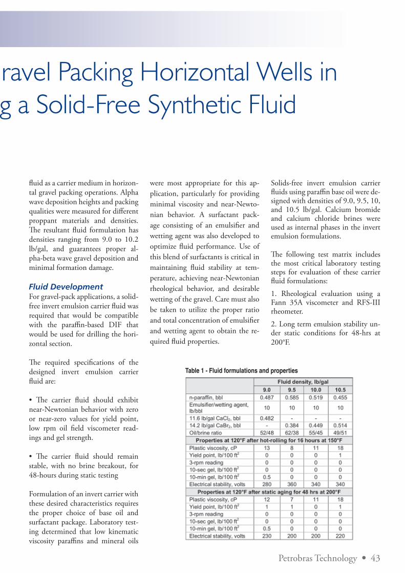
Petrobras Technology • 43
A Novel Approach for Drilling and Gravel Packing Horizontal Wells in the Presence of Reactive Shales Using a Solid-Free Synthetic Fluid
fluid as a carrier medium in horizon-tal gravel packing operations. Alpha wave deposition heights and packing qualities were measured for different proppant materials and densities. The resultant fluid formulation has densities ranging from 9.0 to 10.2 lb/gal, and guarantees proper al-pha-beta wave gravel deposition and minimal formation damage.
Fluid DevelopmentFor gravel-pack applications, a solid-free invert emulsion carrier fluid was required that would be compatible with the paraffin-based DIF that would be used for drilling the hori-zontal section.
The required specifications of the designed invert emulsion carrier fluid are:
• The carrier fluid should exhibit near-Newtonian behavior with zero or near-zero values for yield point, low rpm oil field viscometer read-ings and gel strength.
• The carrier fluid should remain stable, with no brine breakout, for 48-hours during static testing
Formulation of an invert carrier with these desired characteristics requires the proper choice of base oil and surfactant package. Laboratory test-ing determined that low kinematic viscosity paraffins and mineral oils
were most appropriate for this ap-plication, particularly for providing minimal viscosity and near-Newto-nian behavior. A surfactant pack-age consisting of an emulsifier and wetting agent was also developed to optimize fluid performance. Use of this blend of surfactants is critical in maintaining fluid stability at tem-perature, achieving near-Newtonian rheological behavior, and desirable wetting of the gravel. Care must also be taken to utilize the proper ratio and total concentration of emulsifier and wetting agent to obtain the re-quired fluid properties.
Solids-free invert emulsion carrier fluids using paraffin base oil were de-signed with densities of 9.0, 9.5, 10, and 10.5 lb/gal. Calcium bromide and calcium chloride brines were used as internal phases in the invert emulsion formulations.
The following test matrix includes the most critical laboratory testing steps for evaluation of these carrier fluid formulations:
1. Rheological evaluation using a Fann 35A viscometer and RFS-III rheometer.
2. Long term emulsion stability un-der static conditions for 48-hrs at 200°F.
Table 1 - Fluid formulations and properties
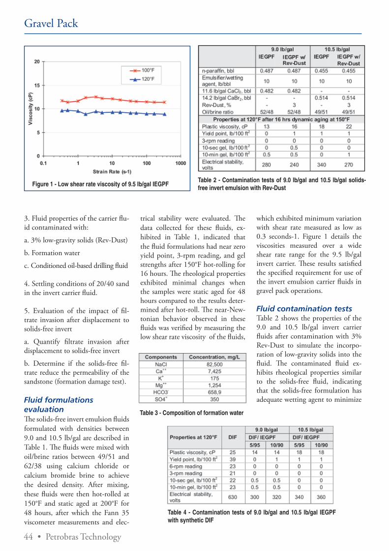
44 • Petrobras Technology
3. Fluid properties of the carrier flu-id contaminated with:
a. 3% low-gravity solids (Rev-Dust)
b. Formation water
c. Conditioned oil-based drilling fluid
4. Settling conditions of 20/40 sand in the invert carrier fluid.
5. Evaluation of the impact of fil-trate invasion after displacement to solids-free invert
a. Quantify filtrate invasion after displacement to solids-free invert
b. Determine if the solids-free fil-trate reduce the permeability of the sandstone (formation damage test).
Fluid formulations evaluationThe solids-free invert emulsion fluids formulated with densities between 9.0 and 10.5 lb/gal are described in Table 1. The fluids were mixed with oil/brine ratios between 49/51 and 62/38 using calcium chloride or calcium bromide brine to achieve the desired density. After mixing, these fluids were then hot-rolled at 150°F and static aged at 200°F for 48 hours, after which the Fann 35 viscometer measurements and elec-
Figure 1 - Low shear rate viscosity of 9.5 lb/gal IEGPF
trical stability were evaluated. The data collected for these fluids, ex-hibited in Table 1, indicated that the fluid formulations had near zero yield point, 3-rpm reading, and gel strengths after 150°F hot-rolling for 16 hours. The rheological properties exhibited minimal changes when the samples were static aged for 48 hours compared to the results deter-mined after hot-roll. The near-New-tonian behavior observed in these fluids was verified by measuring the low shear rate viscosity of the fluids,
Table 2 - Contamination tests of 9.0 lb/gal and 10.5 lb/gal solids-free invert emulsion with Rev-Dust
Table 3 - Composition of formation water
Table 4 - Contamination tests of 9.0 lb/gal and 10.5 lb/gal IEGPF with synthetic DIF
which exhibited minimum variation with shear rate measured as low as 0.3 seconds-1. Figure 1 details the viscosities measured over a wide shear rate range for the 9.5 lb/gal invert carrier. These results satisfied the specified requirement for use of the invert emulsion carrier fluids in gravel pack operations.
Fluid contamination testsTable 2 shows the properties of the 9.0 and 10.5 lb/gal invert carrier fluids after contamination with 3% Rev-Dust to simulate the incorpo-ration of low-gravity solids into the fluid. The contaminated fluid ex-hibits rheological properties similar to the solids-free fluid, indicating that the solids-free formulation has adequate wetting agent to minimize
Gravel Pack
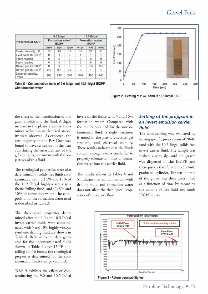
Petrobras Technology • 45
the effect of the introduction of low gravity solids into the fluid. A slight increase in the plastic viscosity and a minor reduction in electrical stabil-ity were observed. As expected, the vast majority of the Rev-Dust was found to have settled out in the heat cup during the measurement of the gel strengths, consistent with the ob-jectives of this fluid.
The rheological properties were also determined for solids-free fluids con-taminated with: (1) 5% and 10% of the 10.5 lb/gal highly-viscous syn-thetic drilling fluid; and (2) 5% and 10% of formation water. The com-position of the formation water used is described in Table 3.
The rheological properties deter-mined after the 9.0 and 10.5 lb/gal invert carrier fluids were contami-nated with 5 and 10% highly-viscous synthetic drilling fluid are shown in Table 4. Relative to the data gath-ered for the uncontaminated fluids shown in Table 1 after 150°F hot-rolling for 16 hours, the rheological properties determined for the con-taminated fluids change very little.
Table 5 exhibits the effect of con-taminating the 9.0 and 10.5 lb/gal
Table 5 - Contamination tests of 9.0 lb/gal and 10.5 lb/gal IEGPF with formation water
Gravel Pack
invert carrier fluids with 5 and 10% formation water. Compared with the results obtained for the uncon-taminated fluid, a slight variation is noted in the plastic viscosity, gel strength, and electrical stability. These results indicate that the fluids contain enough excess emulsifier to properly tolerate an influx of forma-tion water into the carrier fluid.
The results shown in Tables 4 and 5 indicate that contamination with drilling fluid and formation water does not affect the rheological prop-erties of the carrier fluid.
Figure 2 - Settling of 20/40 sand in 10.5 lb/gal IEGPF
Settling of the proppant in an invert emulsion carrier fluidThe sand settling was evaluated by mixing specific proportions of 20/40 sand with the 10.5 lb/gal solids-free invert carrier fluid. The sample was shaken vigorously until the gravel was dispersed in the IEGPF, and then quickly transferred to a 500-mL graduated cylinder. The settling rate of the gravel was then determined as a function of time by recording the volume of free fluid and sand/IEGPF slurry.
Figure 3 - Return permeability test
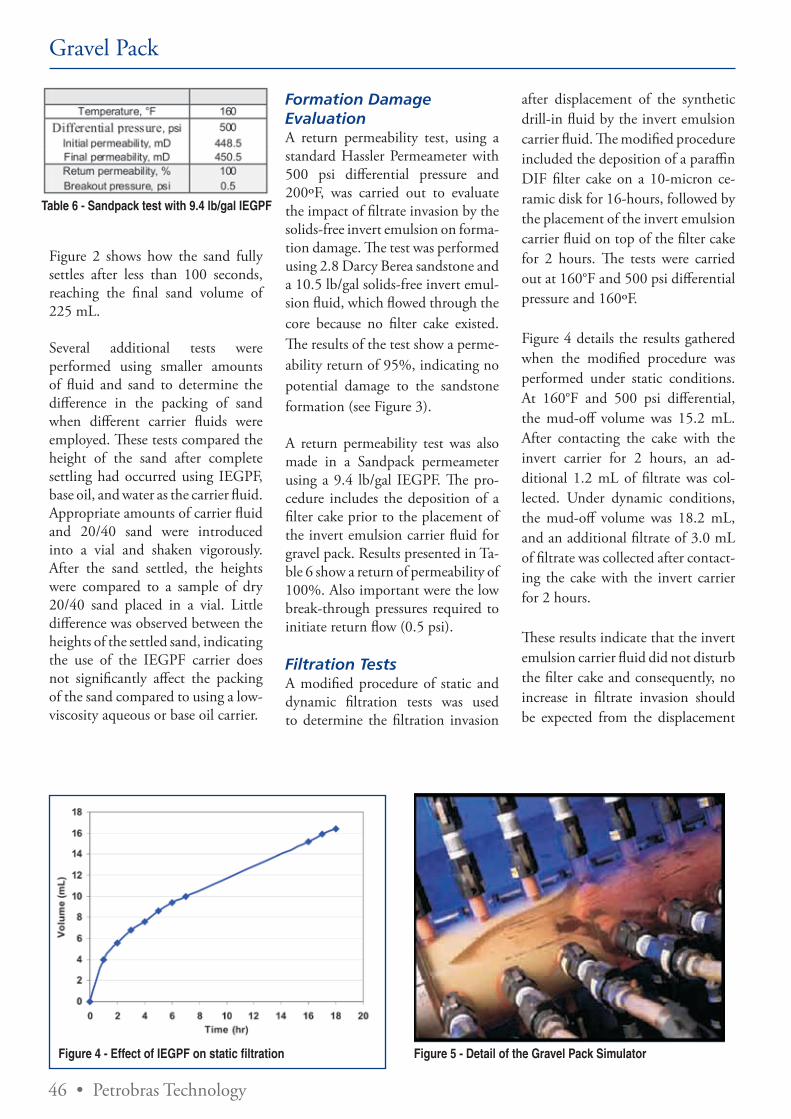
46 • Petrobras Technology
Gravel Pack
Table 6 - Sandpack test with 9.4 lb/gal IEGPF
Figure 2 shows how the sand fully settles after less than 100 seconds, reaching the final sand volume of 225 mL.
Several additional tests were performed using smaller amounts of fluid and sand to determine the difference in the packing of sand when different carrier fluids were employed. These tests compared the height of the sand after complete settling had occurred using IEGPF, base oil, and water as the carrier fluid. Appropriate amounts of carrier fluid and 20/40 sand were introduced into a vial and shaken vigorously. After the sand settled, the heights were compared to a sample of dry 20/40 sand placed in a vial. Little difference was observed between the heights of the settled sand, indicating the use of the IEGPF carrier does not significantly affect the packing of the sand compared to using a low-viscosity aqueous or base oil carrier.
Figure 4 - Effect of IEGPF on static filtration
Formation Damage Evaluation A return permeability test, using a standard Hassler Permeameter with 500 psi differential pressure and 200ºF, was carried out to evaluate the impact of filtrate invasion by the solids-free invert emulsion on forma-tion damage. The test was performed using 2.8 Darcy Berea sandstone and a 10.5 lb/gal solids-free invert emul-sion fluid, which flowed through the core because no filter cake existed. The results of the test show a perme-ability return of 95%, indicating no potential damage to the sandstone formation (see Figure 3).
A return permeability test was also made in a Sandpack permeameter using a 9.4 lb/gal IEGPF. The pro-cedure includes the deposition of a filter cake prior to the placement of the invert emulsion carrier fluid for gravel pack. Results presented in Ta-ble 6 show a return of permeability of 100%. Also important were the low break-through pressures required to initiate return flow (0.5 psi).
Filtration TestsA modified procedure of static and dynamic filtration tests was used to determine the filtration invasion
after displacement of the synthetic drill-in fluid by the invert emulsion carrier fluid. The modified procedure included the deposition of a paraffin DIF filter cake on a 10-micron ce-ramic disk for 16-hours, followed by the placement of the invert emulsion carrier fluid on top of the filter cake for 2 hours. The tests were carried out at 160°F and 500 psi differential pressure and 160ºF.
Figure 4 details the results gathered when the modified procedure was performed under static conditions. At 160°F and 500 psi differential, the mud-off volume was 15.2 mL. After contacting the cake with the invert carrier for 2 hours, an ad-ditional 1.2 mL of filtrate was col-lected. Under dynamic conditions, the mud-off volume was 18.2 mL, and an additional filtrate of 3.0 mL of filtrate was collected after contact-ing the cake with the invert carrier for 2 hours.
These results indicate that the invert emulsion carrier fluid did not disturb the filter cake and consequently, no increase in filtrate invasion should be expected from the displacement
Figure 5 - Detail of the Gravel Pack Simulator
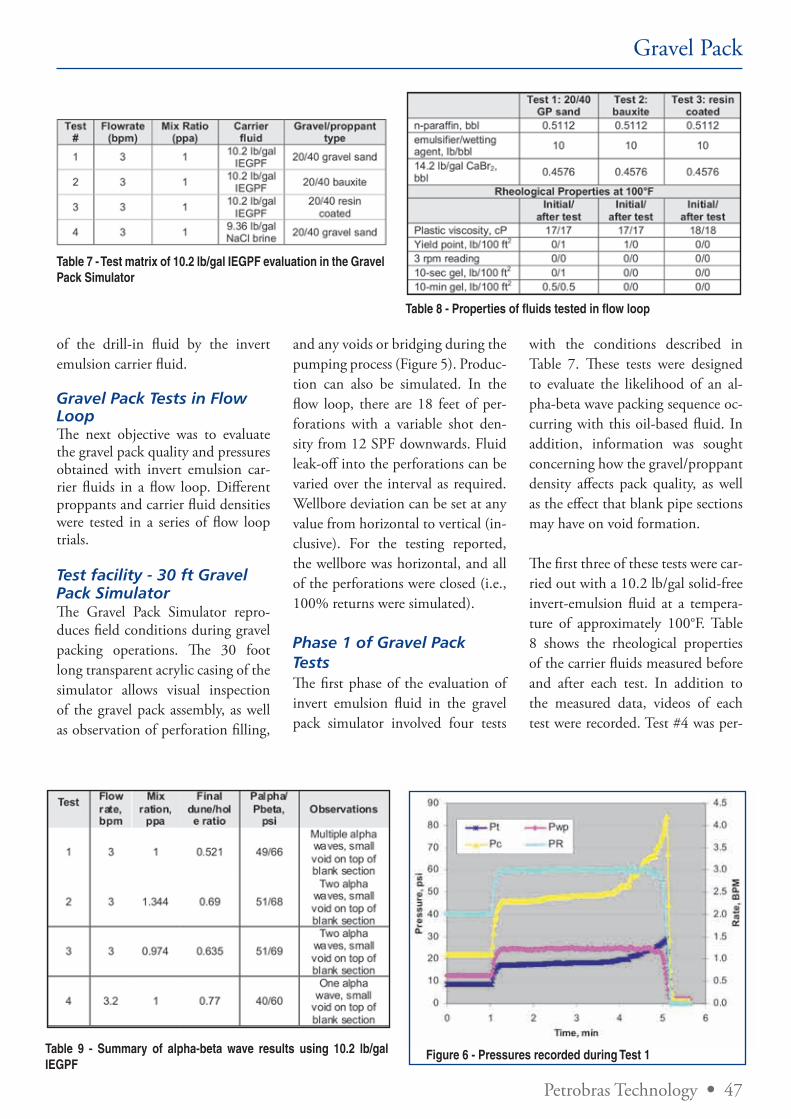
Petrobras Technology • 47
Gravel Pack
Table 7 - Test matrix of 10.2 lb/gal IEGPF evaluation in the Gravel Pack Simulator
Table 8 - Properties of fluids tested in flow loop
of the drill-in fluid by the invert emulsion carrier fluid.
Gravel Pack Tests in Flow LoopThe next objective was to evaluate the gravel pack quality and pressures obtained with invert emulsion car-rier fluids in a flow loop. Different proppants and carrier fluid densities were tested in a series of flow loop trials.
Test facility - 30 ft Gravel Pack SimulatorThe Gravel Pack Simulator repro-duces field conditions during gravel packing operations. The 30 foot long transparent acrylic casing of the simulator allows visual inspection of the gravel pack assembly, as well as observation of perforation filling,
Table 9 - Summary of alpha-beta wave results using 10.2 lb/gal IEGPF
Figure 6 - Pressures recorded during Test 1
and any voids or bridging during the pumping process (Figure 5). Produc-tion can also be simulated. In the flow loop, there are 18 feet of per-forations with a variable shot den-sity from 12 SPF downwards. Fluid leak-off into the perforations can be varied over the interval as required. Wellbore deviation can be set at any value from horizontal to vertical (in-clusive). For the testing reported, the wellbore was horizontal, and all of the perforations were closed (i.e., 100% returns were simulated).
Phase 1 of Gravel Pack TestsThe first phase of the evaluation of invert emulsion fluid in the gravel pack simulator involved four tests
with the conditions described in Table 7. These tests were designed to evaluate the likelihood of an al-pha-beta wave packing sequence oc-curring with this oil-based fluid. In addition, information was sought concerning how the gravel/proppant density affects pack quality, as well as the effect that blank pipe sections may have on void formation.
The first three of these tests were car-ried out with a 10.2 lb/gal solid-free invert-emulsion fluid at a tempera-ture of approximately 100°F. Table 8 shows the rheological properties of the carrier fluids measured before and after each test. In addition to the measured data, videos of each test were recorded. Test #4 was per-
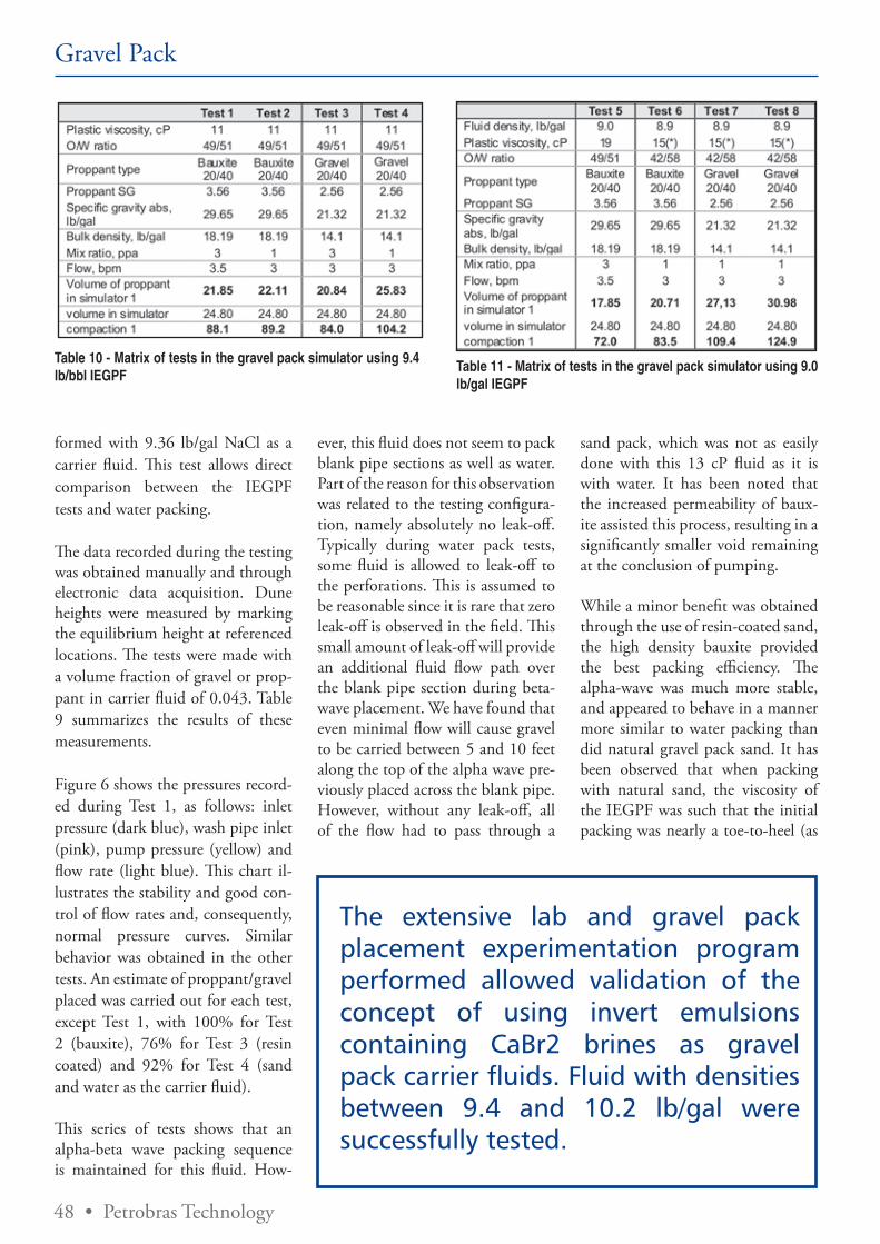
48 • Petrobras Technology
Gravel Pack
formed with 9.36 lb/gal NaCl as a carrier fluid. This test allows direct comparison between the IEGPF tests and water packing.
The data recorded during the testing was obtained manually and through electronic data acquisition. Dune heights were measured by marking the equilibrium height at referenced locations. The tests were made with a volume fraction of gravel or prop-pant in carrier fluid of 0.043. Table 9 summarizes the results of these measurements.
Figure 6 shows the pressures record-ed during Test 1, as follows: inlet pressure (dark blue), wash pipe inlet (pink), pump pressure (yellow) and flow rate (light blue). This chart il-lustrates the stability and good con-trol of flow rates and, consequently, normal pressure curves. Similar behavior was obtained in the other tests. An estimate of proppant/gravel placed was carried out for each test, except Test 1, with 100% for Test 2 (bauxite), 76% for Test 3 (resin coated) and 92% for Test 4 (sand and water as the carrier fluid).
This series of tests shows that an alpha-beta wave packing sequence is maintained for this fluid. How-
ever, this fluid does not seem to pack blank pipe sections as well as water. Part of the reason for this observation was related to the testing configura-tion, namely absolutely no leak-off. Typically during water pack tests, some fluid is allowed to leak-off to the perforations. This is assumed to be reasonable since it is rare that zero leak-off is observed in the field. This small amount of leak-off will provide an additional fluid flow path over the blank pipe section during beta-wave placement. We have found that even minimal flow will cause gravel to be carried between 5 and 10 feet along the top of the alpha wave pre-viously placed across the blank pipe. However, without any leak-off, all of the flow had to pass through a
sand pack, which was not as easily done with this 13 cP fluid as it is with water. It has been noted that the increased permeability of baux-ite assisted this process, resulting in a significantly smaller void remaining at the conclusion of pumping.
While a minor benefit was obtained through the use of resin-coated sand, the high density bauxite provided the best packing efficiency. The alpha-wave was much more stable, and appeared to behave in a manner more similar to water packing than did natural gravel pack sand. It has been observed that when packing with natural sand, the viscosity of the IEGPF was such that the initial packing was nearly a toe-to-heel (as
Table 10 - Matrix of tests in the gravel pack simulator using 9.4 lb/bbl IEGPF
Table 11 - Matrix of tests in the gravel pack simulator using 9.0 lb/gal IEGPF
The extensive lab and gravel pack placement experimentation program performed allowed validation of the concept of using invert emulsions containing CaBr2 brines as gravel pack carrier fluids. Fluid with densities between 9.4 and 10.2 lb/gal were successfully tested.
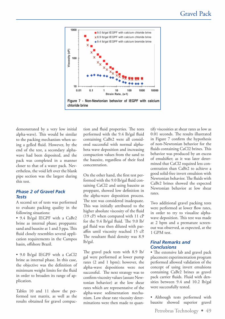
Petrobras Technology • 49
Figure 7 - Non-Newtonian behavior of IEGPF with calcium chloride brine
Gravel Pack
demonstrated by a very low initial alpha-wave). This would be similar to the packing mechanism when us-ing a gelled fluid. However, by the end of the test, a secondary alpha-wave had been deposited, and the pack was completed in a manner closer to that of a water pack. Nev-ertheless, the void left over the blank pipe section was the largest during this test.
Phase 2 of Gravel Pack TestsA second set of tests was performed to evaluate packing quality in the following situations: • 9.4 lb/gal IEGPF with a CaBr2 brine as internal phase; proppants: sand and bauxite at 1 and 3 ppa. This fluid closely resembles several appli-cation requirements in the Campos basin, offshore Brazil.
• 9.0 lb/gal IEGPF with a CaCl2 brine as internal phase. In this case, the objective was the definition of minimum weight limits for the fluid in order to broaden its range of ap-plication.
Tables 10 and 11 show the per-formed test matrix, as well as the results obtained for gravel compac-
tion and fluid properties. The tests performed with the 9.4 lb/gal fluid containing CaBr2 were all consid-ered successful with normal alpha-beta wave deposition and increasing compaction values from the sand to the bauxite, regardless of their feed concentration.
On the other hand, the first test per-formed with the 9.0 lb/gal fluid con-taining CaCl2 and using bauxite as proppant, showed low definition in the alpha-wave deposition process. The test was considered inadequate. This was initially attributed to the higher absolute viscosity of the fluid (19 cP) when compared with 11 cP for the 9.4 lb/gal fluid. The 9.0 lb/gal fluid was then diluted with par-affin until viscosity reached 15 cP. The resultant fluid density was 8.9 lb/gal.
The gravel pack tests with 8.9 lb/gal were performed at lower pump rates (2 and 1 bpm); however, the alpha-wave depositions were not successful. The next strategy was to confirm viscosity values (assure New-tonian behavior) at the low shear rates which are representative of the alpha-wave sedimentation mecha-nism. Low shear rate viscosity deter-minations were then made to quan-
tify viscosities at shear rates as low as 0.01 seconds. The results illustrated in Figure 7 confirm the hypothesis of non-Newtonian behavior for the fluids containing CaCl2 brines. This behavior was produced by an excess of emulsifier; as it was later deter-mined that CaCl2 required less con-centration than CaBr2 to achieve a good solid-free invert emulsion with Newtonian behavior. The fluids with CaBr2 brines showed the expected Newtonian behavior at low shear rates.
Two additional gravel packing tests were performed at lower flow rates, in order to try to visualize alpha-wave deposition. This test was made at 2 bpm and a premature screen-out was observed, as expected, at the 1 GPM test.
Final Remarks and Conclusions• The extensive lab and gravel pack placement experimentation program performed allowed validation of the concept of using invert emulsions containing CaBr2 brines as gravel pack carrier fluids. Fluid with den-sities between 9.4 and 10.2 lb/gal were successfully tested.
• Although tests performed with bauxite showed superior gravel
50 • Petrobras Technology
• IEGPF = Invert emulsion gravel pack fluid• OHGP = open-hole gravel pack • DIF = drill-in fluid• WBM = Water Based Mud• OBM = Oil Based Mud• CaBr2 = calcium bromide• CaCl2 = calcium chloride• NaCl = sodium chloride• bpm = barrels per minute• Palpha = casing pressure at conclusion of alpha wave• Pbeta = casing pressure at conclusion of beta wave• lb/bbl = pounds per barrel• lb/gal = pounds per gallon• ft = feet• °F = temperature in Fahrenheit• °C = temperature in Celsius
Nomenclature
placement, all proppants achieved satisfactory results. The pumping of 3 ppa proppant concentration seemed to be an interesting alterna-tive for the reduction of operational time and of fluid volume require-ments.
• Tests performed with the 9.0 lb/gal IEGPF with calcium chloride brine showed poor alpha-wave deposition due to the non-Newtonian behavior at low shear rates of the fluid formu-lation. The types of brine and sur-factant concentration are important parameters that affect the low shear rate viscosity.
• The extension of the concept for fluids designed with densities in the range of 9 lb/gal is certainly possible, but still requires some future lab ef-fort.
• The strategy for implementation of this technology in the field includes the following steps:
1. Perform three gravel pack opera-tions at wells with conventional de-signs, utilizing the IEGP fluid con-taining CaBr2
2. With the operational success of the conventional well designs, per-form gravel pack operations with the proposed fluid in wells where the buildup and reservoir sections have been drilled in a single phase
(new development wells or re-entry wells).
References1. Mathis, S.P., Costa, L.A.G., De Sa, A.N., Calderon, A., Arango, J.C., Macdonald, K., and Hebert, S. A., “Horizontal Gravel Packing Suc-cessfully Moved to Deepwater Float-ing Rig Environment”, SPE 56783, presented at the 1999 SPE Annual Technical Conference and Exhibit, Houston, Texas, 3-6 October, 1999.
2. McKay G., Benett C.L., and Gil-christ, J.M., “High Angle OHGP’s in Sand/shale Sequences: a Case His-tory Using a Formate Drill-in” SPE 58731 presented at the SPE Inter-national Symposium on Formation Damage Control, Lafayette,LA, Feb. 23-24 2000.
3. Scheuerman, R.F., “A New Look at Gravel-Pack Carrier fluids”, SPE 12476, SPE Production Engineer-ing, January 1986, pp 9-16.
4. Penberthy, W.L.Jr., Bickham, K.L., Nguyen, H.T., Paulley, T.A., “Gravel Placement in Horizontal Wells”, SPE 31147, presented at the SPE Asia Pacific Oil and Gas Con-ference and Exhibition, Brisbane, Australia, 16-18 October 2000.
5. Chambers, M.R., Hebert, D.B., and Shuchart, C.E., “Successful Application of Oil-Based Drilling Fluids in Subsea, Horizontal Gravel-Packed Wells in West Africa”, SPE 58743, presented at the SPE Inter-national Symposium on Formation Damage Control, Lafayette, LA, Feb. 23-24, 2000.
6. Gilchrist, J.M., Sutton, L.W.Jr., and Elliott, F.J., “Advancing Hori-zontal Well Sand Control Technol-ogy: An OHGP Using Synthetic OBM”, SPE 48976 in Proceedings of SPE Annual Meeting, New Or-leans, LA, Sep. 27-30, 1998.
7. Wagner, M., Webb, T., Maharaj, M., Twynam, A., Green, T., Sala-mat, G., and Parlar, M., “Horizontal Drilling and Openhole Gravel Pack-ing With Oil-Based Fluids – An In-dustry Milestone”, SPE 87648-PA, SPE Drilling and Completion Vol. 21 No. 1 pp. 32-43, March 2006.
8. Donalson. A.; Vitthal, S., Welch, J.C., and Nguyen, P.D., “Invert Gravel Pack Carrier Fluid”, SPE 71669, presented at the Annual Technical Conference and Exhibi-tion, New Orleans, LA, 30 Septem-ber -3 October 2001.
The extension of the concept for fluids designed with densities in the range of 9 lb/gal is certainly possible, but still requires some fu-ture lab effort.
Gravel Pack
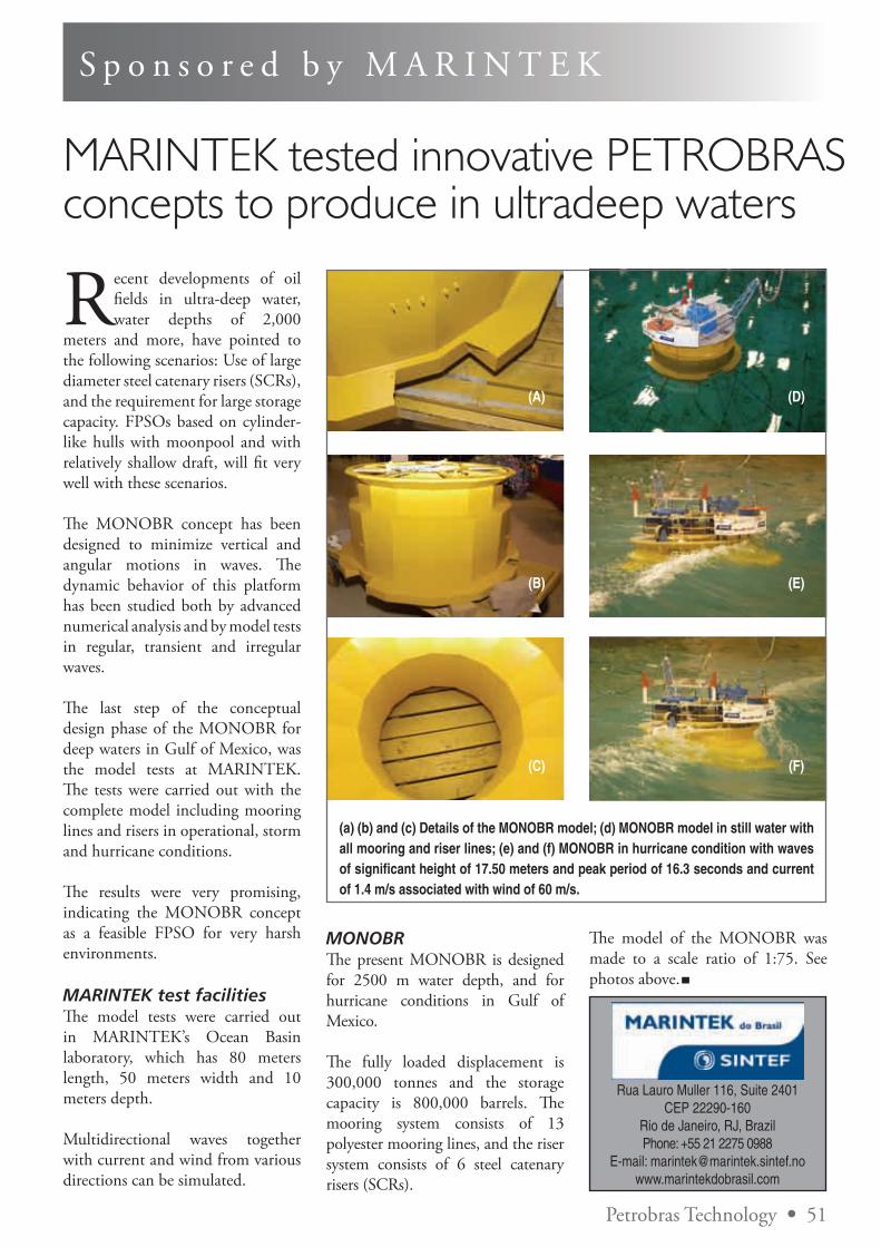
Petrobras Technology • 51
S p o n s o r e d b y M A R I N T E K
MARINTEK tested innovative PETROBRAS concepts to produce in ultradeep waters
Recent developments of oil fields in ultra-deep water, water depths of 2,000
meters and more, have pointed to the following scenarios: Use of large diameter steel catenary risers (SCRs), and the requirement for large storage capacity. FPSOs based on cylinder-like hulls with moonpool and with relatively shallow draft, will fit very well with these scenarios.
The MONOBR concept has been designed to minimize vertical and angular motions in waves. The dynamic behavior of this platform has been studied both by advanced numerical analysis and by model tests in regular, transient and irregular waves.
The last step of the conceptual design phase of the MONOBR for deep waters in Gulf of Mexico, was the model tests at MARINTEK. The tests were carried out with the complete model including mooring lines and risers in operational, storm and hurricane conditions.
The results were very promising, indicating the MONOBR concept as a feasible FPSO for very harsh environments.
MARINTEK test facilities The model tests were carried out in MARINTEK’s Ocean Basin laboratory, which has 80 meters length, 50 meters width and 10 meters depth.
Multidirectional waves together with current and wind from various directions can be simulated.
MONOBR The present MONOBR is designed for 2500 m water depth, and for hurricane conditions in Gulf of Mexico.
The fully loaded displacement is 300,000 tonnes and the storage capacity is 800,000 barrels. The mooring system consists of 13 polyester mooring lines, and the riser system consists of 6 steel catenary risers (SCRs).
The model of the MONOBR was made to a scale ratio of 1:75. See photos above.
(a) (b) and (c) Details of the MONOBR model; (d) MONOBR model in still water with all mooring and riser lines; (e) and (f) MONOBR in hurricane condition with waves of significant height of 17.50 meters and peak period of 16.3 seconds and current of 1.4 m/s associated with wind of 60 m/s.
(A)
(B)
(C)
(D)
(E)
(F)
Rua Lauro Muller 116, Suite 2401 CEP 22290-160
Rio de Janeiro, RJ, BrazilPhone: +55 21 2275 0988
E-mail: [email protected]
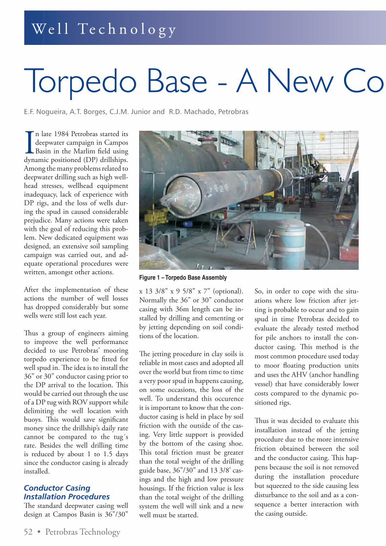
52 • Petrobras Technology
We l l Te c h n o l o g y
Torpedo Base - A New Conductor Installation ProcessE.F. Nogueira, A.T. Borges, C.J.M. Junior and R.D. Machado, Petrobras
In late 1984 Petrobras started its deepwater campaign in Campos Basin in the Marlim field using
dynamic positioned (DP) drillships. Among the many problems related to deepwater drilling such as high well-head stresses, wellhead equipment inadequacy, lack of experience with DP rigs, and the loss of wells dur-ing the spud in caused considerable prejudice. Many actions were taken with the goal of reducing this prob-lem. New dedicated equipment was designed, an extensive soil sampling campaign was carried out, and ad-equate operational procedures were written, amongst other actions.
After the implementation of these actions the number of well losses has dropped considerably but some wells were still lost each year.
Thus a group of engineers aiming to improve the well performance decided to use Petrobras' mooring torpedo experience to be fitted for well spud in. The idea is to install the 36” or 30” conductor casing prior to the DP arrival to the location. This would be carried out through the use of a DP tug with ROV support while delimiting the well location with buoys. This would save significant money since the drillship’s daily rate cannot be compared to the tug´s rate. Besides the well drilling time is reduced by about 1 to 1.5 days since the conductor casing is already installed.
Conductor Casing Installation ProceduresThe standard deepwater casing well design at Campos Basin is 36”/30”
x 13 3/8” x 9 5/8” x 7” (optional). Normally the 36” or 30” conductor casing with 36m length can be in-stalled by drilling and cementing or by jetting depending on soil condi-tions of the location.
The jetting procedure in clay soils is reliable in most cases and adopted all over the world but from time to time a very poor spud in happens causing, on some occasions, the loss of the well. To understand this occurence it is important to know that the con-ductor casing is held in place by soil friction with the outside of the cas-ing. Very little support is provided by the bottom of the casing shoe. This total friction must be greater than the total weight of the drilling guide base, 36”/30” and 13 3/8’ cas-ings and the high and low pressure housings. If the friction value is less than the total weight of the drilling system the well will sink and a new well must be started.
So, in order to cope with the situ-ations where low friction after jet-ting is probable to occur and to gain spud in time Petrobras decided to evaluate the already tested method for pile anchors to install the con-ductor casing. This method is the most common procedure used today to moor floating production units and uses the AHV (anchor handling vessel) that have considerably lower costs compared to the dynamic po-sitioned rigs.
Thus it was decided to evaluate this installation instead of the jetting procedure due to the more intensive friction obtained between the soil and the conductor casing. This hap-pens because the soil is not removed during the installation procedure but squeezed to the side causing less disturbance to the soil and as a con-sequence a better interaction with the casing outside.
Figure 1 – Torpedo Base Assembly
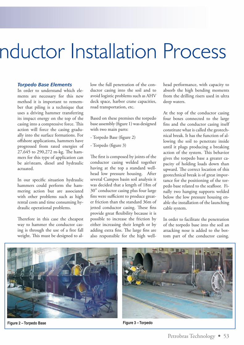
Petrobras Technology • 53
Torpedo Base - A New Conductor Installation ProcessTorpedo Base ElementsIn order to understand which ele-ments are necessary for this new method it is important to remem-ber that piling is a technique that uses a driving hammer transferring its impact energy on the top of the casing into a compressive force. This action will force the casing gradu-ally into the surface formations. For offshore applications, hammers have progressed from rated energies of 27,645 to 290,272 m-kg. The ham-mers for this type of application can be air/steam, diesel and hydraulic actuated.
In our specific situation hydraulic hammers could perform the ham-mering action but are associated with other problems such as high rental costs and time consuming hy-draulic operational problems.
Therefore in this case the cheapest way to hammer the conductor cas-ing is through the use of a free fall weight. This must be designed to al-
low the full penetration of the con-ductor casing into the soil and to avoid logistic problems such as AHV deck space, harbor crane capacities, road transportation, etc.
Based on these premises the torpedo base assembly (figure 1) was designed with two main parts:
- Torpedo Base (figure 2)
- Torpedo (figure 3)
The first is composed by joints of the conductor casing welded together having at the top a standard well-head low pressure housing. After several Campos basin soil analysis it was decided that a length of 18m of 30” conductor casing plus four large fins were sufficient to produce great-er friction than the standard 36m of jetted conductor casing. These fins provide great flexibility because it is possible to increase the friction by either increasing their length or by adding extra fins. The large fins are also responsible for the high well-
Figure 2 – Torpedo Base Figure 3 – Torpedo
head performance, with capacity to absorb the high bending moments from the drilling risers used in ultra deep waters.
At the top of the conductor casing four boxes connected to the large fins and the conductor casing itself constitute what is called the geotech-nical break. It has the function of al-lowing the soil to penetrate inside until it plugs producing a breaking action of the system. This behavior gives the torpedo base a greater ca-pacity of holding loads down than upward. The correct location of this geotechnical break is of great impor-tance for the positioning of the tor-pedo base related to the seafloor. Fi-nally two hanging supports welded below the low pressure housing en-able the installation of the launching cable system.
In order to facilitate the penetration of the torpedo base into the soil an attacking nose is added to the bot-tom part of the conductor casing.
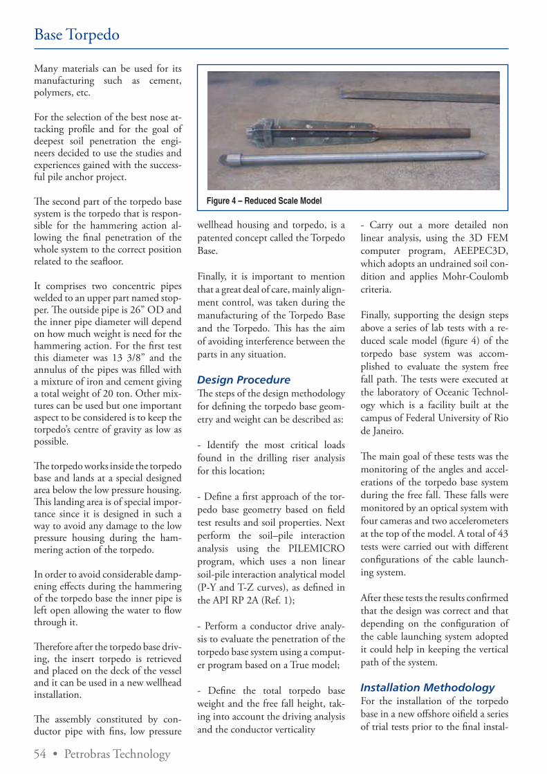
54 • Petrobras Technology
Base Torpedo
Many materials can be used for its manufacturing such as cement, polymers, etc.
For the selection of the best nose at-tacking profile and for the goal of deepest soil penetration the engi-neers decided to use the studies and experiences gained with the success-ful pile anchor project.
The second part of the torpedo base system is the torpedo that is respon-sible for the hammering action al-lowing the final penetration of the whole system to the correct position related to the seafloor.
It comprises two concentric pipes welded to an upper part named stop-per. The outside pipe is 26” OD and the inner pipe diameter will depend on how much weight is need for the hammering action. For the first test this diameter was 13 3/8” and the annulus of the pipes was filled with a mixture of iron and cement giving a total weight of 20 ton. Other mix-tures can be used but one important aspect to be considered is to keep the torpedo’s centre of gravity as low as possible.
The torpedo works inside the torpedo base and lands at a special designed area below the low pressure housing. This landing area is of special impor-tance since it is designed in such a way to avoid any damage to the low pressure housing during the ham-mering action of the torpedo.
In order to avoid considerable damp-ening effects during the hammering of the torpedo base the inner pipe is left open allowing the water to flow through it.
Therefore after the torpedo base driv-ing, the insert torpedo is retrieved and placed on the deck of the vessel and it can be used in a new wellhead installation.
The assembly constituted by con-ductor pipe with fins, low pressure
wellhead housing and torpedo, is a patented concept called the Torpedo Base.
Finally, it is important to mention that a great deal of care, mainly align-ment control, was taken during the manufacturing of the Torpedo Base and the Torpedo. This has the aim of avoiding interference between the parts in any situation.
Design ProcedureThe steps of the design methodology for defining the torpedo base geom-etry and weight can be described as:
- Identify the most critical loads found in the drilling riser analysis for this location;
- Define a first approach of the tor-pedo base geometry based on field test results and soil properties. Next perform the soil–pile interaction analysis using the PILEMICRO program, which uses a non linear soil-pile interaction analytical model (P-Y and T-Z curves), as defined in the API RP 2A (Ref. 1);
- Perform a conductor drive analy-sis to evaluate the penetration of the torpedo base system using a comput-er program based on a True model;
- Define the total torpedo base weight and the free fall height, tak-ing into account the driving analysis and the conductor verticality
- Carry out a more detailed non linear analysis, using the 3D FEM computer program, AEEPEC3D, which adopts an undrained soil con-dition and applies Mohr-Coulomb criteria.
Finally, supporting the design steps above a series of lab tests with a re-duced scale model (figure 4) of the torpedo base system was accom-plished to evaluate the system free fall path. The tests were executed at the laboratory of Oceanic Technol-ogy which is a facility built at the campus of Federal University of Rio de Janeiro.
The main goal of these tests was the monitoring of the angles and accel-erations of the torpedo base system during the free fall. These falls were monitored by an optical system with four cameras and two accelerometers at the top of the model. A total of 43 tests were carried out with different configurations of the cable launch-ing system.
After these tests the results confirmed that the design was correct and that depending on the configuration of the cable launching system adopted it could help in keeping the vertical path of the system.
Installation MethodologyFor the installation of the torpedo base in a new offshore oifield a series of trial tests prior to the final instal-
Figure 4 – Reduced Scale Model
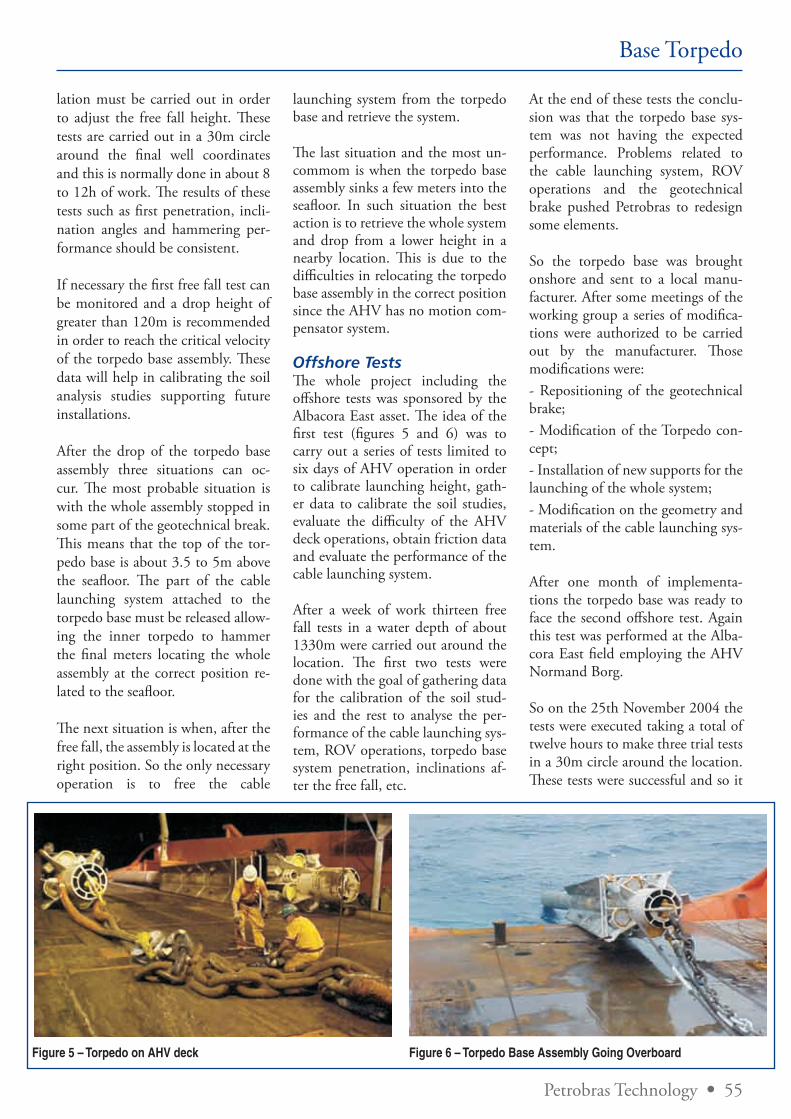
Petrobras Technology • 55
Base Torpedo
lation must be carried out in order to adjust the free fall height. These tests are carried out in a 30m circle around the final well coordinates and this is normally done in about 8 to 12h of work. The results of these tests such as first penetration, incli-nation angles and hammering per-formance should be consistent.
If necessary the first free fall test can be monitored and a drop height of greater than 120m is recommended in order to reach the critical velocity of the torpedo base assembly. These data will help in calibrating the soil analysis studies supporting future installations.
After the drop of the torpedo base assembly three situations can oc-cur. The most probable situation is with the whole assembly stopped in some part of the geotechnical break. This means that the top of the tor-pedo base is about 3.5 to 5m above the seafloor. The part of the cable launching system attached to the torpedo base must be released allow-ing the inner torpedo to hammer the final meters locating the whole assembly at the correct position re-lated to the seafloor.
The next situation is when, after the free fall, the assembly is located at the right position. So the only necessary operation is to free the cable
launching system from the torpedo base and retrieve the system.
The last situation and the most un-commom is when the torpedo base assembly sinks a few meters into the seafloor. In such situation the best action is to retrieve the whole system and drop from a lower height in a nearby location. This is due to the difficulties in relocating the torpedo base assembly in the correct position since the AHV has no motion com-pensator system.
Offshore TestsThe whole project including the offshore tests was sponsored by the Albacora East asset. The idea of the first test (figures 5 and 6) was to carry out a series of tests limited to six days of AHV operation in order to calibrate launching height, gath-er data to calibrate the soil studies, evaluate the difficulty of the AHV deck operations, obtain friction data and evaluate the performance of the cable launching system.
After a week of work thirteen free fall tests in a water depth of about 1330m were carried out around the location. The first two tests were done with the goal of gathering data for the calibration of the soil stud-ies and the rest to analyse the per-formance of the cable launching sys-tem, ROV operations, torpedo base system penetration, inclinations af-ter the free fall, etc.
At the end of these tests the conclu-sion was that the torpedo base sys-tem was not having the expected performance. Problems related to the cable launching system, ROV operations and the geotechnical brake pushed Petrobras to redesign some elements.
So the torpedo base was brought onshore and sent to a local manu-facturer. After some meetings of the working group a series of modifica-tions were authorized to be carried out by the manufacturer. Those modifications were:- Repositioning of the geotechnical brake;- Modification of the Torpedo con-cept;- Installation of new supports for the launching of the whole system;- Modification on the geometry and materials of the cable launching sys-tem.
After one month of implementa-tions the torpedo base was ready to face the second offshore test. Again this test was performed at the Alba-cora East field employing the AHV Normand Borg.
So on the 25th November 2004 the tests were executed taking a total of twelve hours to make three trial tests in a 30m circle around the location. These tests were successful and so it
Figure 5 – Torpedo on AHV deck Figure 6 – Torpedo Base Assembly Going Overboard
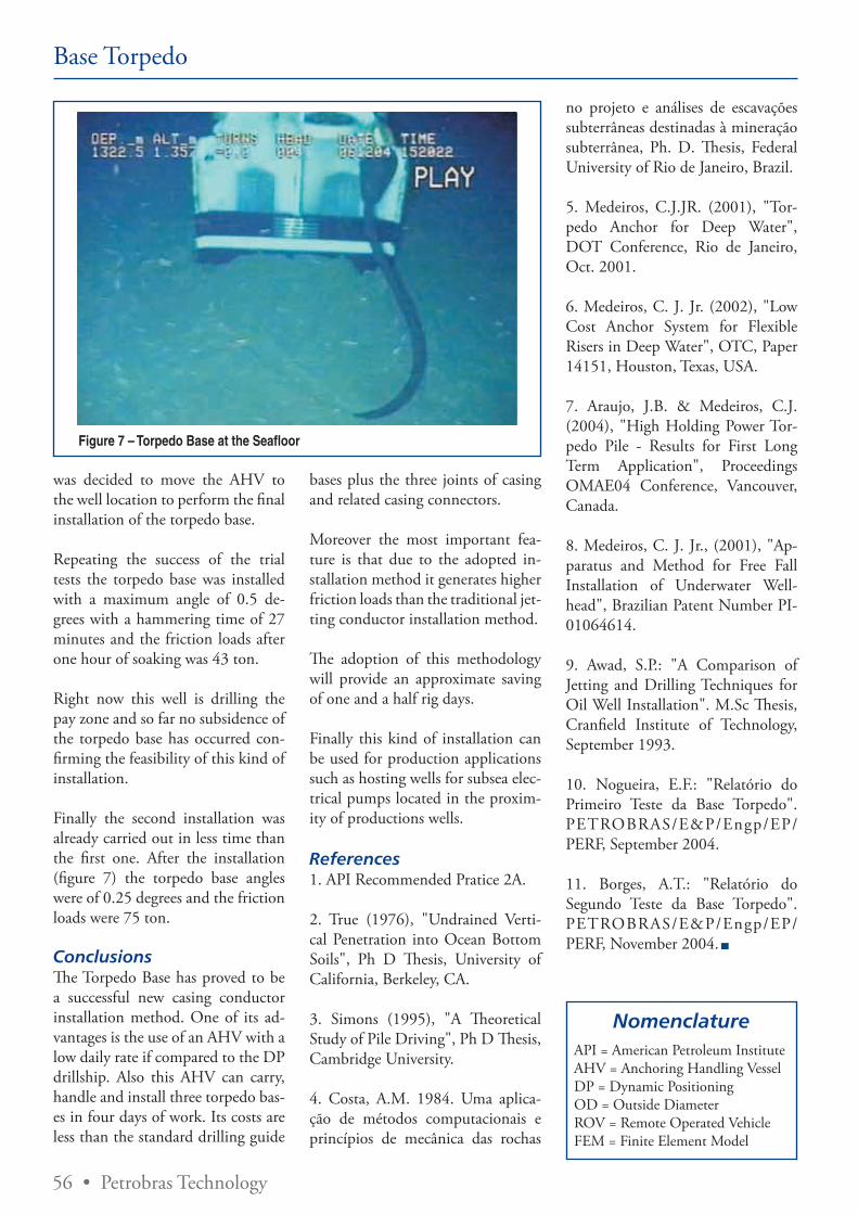
56 • Petrobras Technology
Base Torpedo
was decided to move the AHV to the well location to perform the final installation of the torpedo base.
Repeating the success of the trial tests the torpedo base was installed with a maximum angle of 0.5 de-grees with a hammering time of 27 minutes and the friction loads after one hour of soaking was 43 ton.
Right now this well is drilling the pay zone and so far no subsidence of the torpedo base has occurred con-firming the feasibility of this kind of installation.
Finally the second installation was already carried out in less time than the first one. After the installation (figure 7) the torpedo base angles were of 0.25 degrees and the friction loads were 75 ton.
ConclusionsThe Torpedo Base has proved to be a successful new casing conductor installation method. One of its ad-vantages is the use of an AHV with a low daily rate if compared to the DP drillship. Also this AHV can carry, handle and install three torpedo bas-es in four days of work. Its costs are less than the standard drilling guide
bases plus the three joints of casing and related casing connectors.
Moreover the most important fea-ture is that due to the adopted in-stallation method it generates higher friction loads than the traditional jet-ting conductor installation method.
The adoption of this methodology will provide an approximate saving of one and a half rig days.
Finally this kind of installation can be used for production applications such as hosting wells for subsea elec-trical pumps located in the proxim-ity of productions wells.
References1. API Recommended Pratice 2A.
2. True (1976), "Undrained Verti-cal Penetration into Ocean Bottom Soils", Ph D Thesis, University of California, Berkeley, CA.
3. Simons (1995), "A Theoretical Study of Pile Driving", Ph D Thesis, Cambridge University.
4. Costa, A.M. 1984. Uma aplica-ção de métodos computacionais e princípios de mecânica das rochas
no projeto e análises de escavações subterrâneas destinadas à mineração subterrânea, Ph. D. Thesis, Federal University of Rio de Janeiro, Brazil.
5. Medeiros, C.J.JR. (2001), "Tor-pedo Anchor for Deep Water", DOT Conference, Rio de Janeiro, Oct. 2001.
6. Medeiros, C. J. Jr. (2002), "Low Cost Anchor System for Flexible Risers in Deep Water", OTC, Paper 14151, Houston, Texas, USA.
7. Araujo, J.B. & Medeiros, C.J. (2004), "High Holding Power Tor-pedo Pile - Results for First Long Term Application", Proceedings OMAE04 Conference, Vancouver, Canada.
8. Medeiros, C. J. Jr., (2001), "Ap-paratus and Method for Free Fall Installation of Underwater Well-head", Brazilian Patent Number PI-01064614.
9. Awad, S.P.: "A Comparison of Jetting and Drilling Techniques for Oil Well Installation". M.Sc Thesis, Cranfield Institute of Technology, September 1993.
10. Nogueira, E.F.: "Relatório do Primeiro Teste da Base Torpedo". PETROBRAS/E&P/Engp/EP/PERF, September 2004.
11. Borges, A.T.: "Relatório do Segundo Teste da Base Torpedo". PETROBRAS/E&P/Engp/EP/PERF, November 2004.
Figure 7 – Torpedo Base at the Seafloor
API = American Petroleum InstituteAHV = Anchoring Handling VesselDP = Dynamic PositioningOD = Outside DiameterROV = Remote Operated VehicleFEM = Finite Element Model
Nomenclature

Desde 1957 quando chegou ao Brasil, a Halliburton vem prestando serviços vitais para a indústria nacional de petróleo e gás.
Atualmente com mais de 1.000 empregados nacionais e servindo em várias partes do país, a Halliburton sente um grande orgulho
em contribuir para o progresso de nossa nação e bem-estar de nossos cidadãos. Ao contar com nossas tecnologias inovadoras e
extensa experiência, você tem certeza que conta com uma empresa que prima pela segurança, saúde e qualidade e que tem um
enorme respeito pelo meio-ambiente.
Halliburton do Brasil. Aqui para ficar. Aqui para servir. HALLIBURTON
© 2007 Halliburton. All rights reserved.
H176B-07 BOG Petrobras.qxd:H176B-07 BOG Petrobras.qxd 8/31/07 9:31 AM Page 1
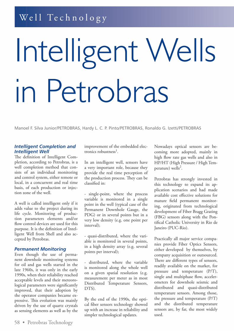
58 • Petrobras Technology
We l l Te c h n o l o g y
Intelligent Wells in PetrobrasManoel F. Silva Junior/PETROBRAS, Hardy L. C. P. Pinto/PETROBRAS, Ronaldo G. Izetti/PETROBRAS
Intelligent Completion and Intelligent Well Th e defi nition of Intelligent Com-pletion, according to Petrobras, is a well completion method that con-sists of an individual monitoring and control system, either remote or local, in a concurrent and real time basis, of each production or injec-tion zone of the well.
A well is called intelligent only if it adds value to the project during its life cycle. Monitoring of produc-tion parameters elements and/or fl ow control devices are used for this purpose. It is the defi nition of Intel-ligent Well from Shell and also ac-cepted by Petrobras.
Permanent MonitoringEven though the use of perma-nent downhole monitoring systems for oil and gas wells started in the late 1960s, it was only in the early 1990s, when their reliability reached acceptable levels and their meteoro-logical parameters were signifi cantly improved, that their adoption by the operator companies became ex-pressive. Th is evolution was mainly driven by the use of quartz crystals as sensing elements as well as by the
improvement of the embedded elec-tronics robustness1.
In an intelligent well, sensors have a very important role, because they provide the real time perception of the production process. Th ey can be classifi ed in:
- single-point, where the process variable is monitored in a single point in the well (typical case of the Permanent Downhole Gauge, the PDG) or in several points but in a very low density (e.g. one point per interval);
- quasi-distributed, where the vari-able is monitored in several points, in a high density array (e.g. several points per interval);
- distributed, where the variable is monitored along the whole well on a given spatial resolution (e.g. measurement per meter as in most Distributed Temperature Sensors, DTS).
By the end of the 1990s, the opti-cal fi ber sensors technology showed up with an increase in reliability and simpler technological updates.
Nowadays optical sensors are be-coming more adopted, mainly in high fl ow rate gas wells and also in HP/HT (High Pressure / High Tem-perature) wells2.
Petrobras has strongly invested in this technology to expand its ap-plication scenarios and had made available cost eff ective solutions for mature fi eld permanent monitor-ing, originated from technological development of Fiber Bragg Grating (FBG) sensors along with the Pon-tifi cal Catholic University in Rio de Janeiro (PUC-Rio).
Practically all major service compa-nies provide Fiber Optics Sensors, either developed by themselves, by company acquisition or outsourced. Th ere are diff erent types of sensors, readily available on the market, for pressure and temperature (P/T), single and multiphase fl ow, acceler-ometers for downhole seismic and distributed and quasi-distributed temperature sensors. Among those, the pressure and temperature (P/T) and the distributed temperature sensors are, by far, the most widely used.

Petrobras Technology • 59
EPRasheed offers specialized services for the Oil and Gas Industry:• Marketing, Media Management,
Supplements and Advertising
• Technical Ghost Writing of company, SPE and industry articles
• Technical Translation of company brochures, product information, technical data, instruction manuals and field applications
• In English, Portuguese, Arabic, Russian and Spanish
Trinidad48-50 Sackville St, Port of SpainTlf: + 1 868 730 6443
London11 Murray St, Camden, NW1 3RETlf + 44 207 193 1602
BrazilAv. Prado Junior, 48 Sala 210 Copacabana Rio de Janeiro Tlf: + 55 21 2510 6238
EPRasheed offers specialized services
Saudi ArabiaPO BOX 3260, Jeddah 21471Tlf + 966 557 276 426
Saudi Arabia c/o FuturewareKingdom of Saudi ArabiaPO BX 705 Al-Khobar 31952Tlf + 44 966 3 8977166
Th e cables used for sensor installa-tion are greatly responsible for the installation success. Th ey need to be chemically protected against the harsh environmental conditions found downhole (high salinity and acidity) and also resist mechanical damage such as shocks against the casing that might happen during in-stallations and workovers. Typically a stainless steel or Inconel tubing is used for protecting the electrical or optical conductor, but other mate-rials can also be used, according to the environmental conditions of the well. Externally to the tubing, a polymeric encapsulation is used to off er chemical protection as well as better anchor points between the
production tubing and the cable protectors.
Optical and electrical cables are very similar regarding chemical and me-chanical protections. In optical ca-bles specifi cally, the hydrogen pres-ence in the environment, associated with higher temperatures can lead to a darkening process of the fi ber for the infrared light usually used. In this case, special fi ber coating and hydrogen scavenging gel can be used in the cable.
Th e connectors and penetrators also play a major role in the permanent monitoring systems.
Remote Flow controlTh e remote fl ow control valves are responsible for allowing selective control of production or injection. Th ey can be actuated hydraulically, electrically or a combination of both (multiplexed). Th e most common type is the hydraulically actuated, in which a balanced piston is used to shift a sliding sleeve to restrict the passage through the valve. Usually, it is used with one opening control line for each valve and a common close control line for the system, to reduce the number of hydraulic lines installed. In electrically actuated valves, an electrical motor is respon-sible for the shifting of the sleeve.
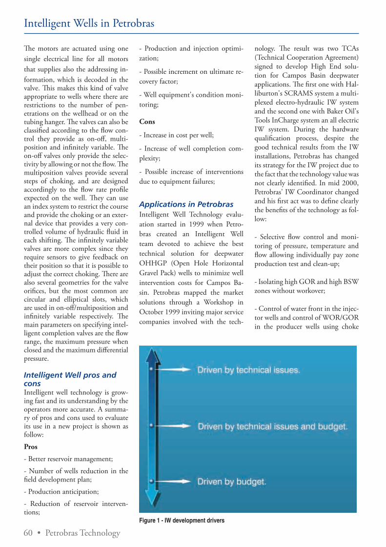
60 • Petrobras Technology
Intelligent Wells in Petrobras
The motors are actuated using one single electrical line for all motors that supplies also the addressing in-formation, which is decoded in the valve. This makes this kind of valve appropriate to wells where there are restrictions to the number of pen-etrations on the wellhead or on the tubing hanger. The valves can also be classified according to the flow con-trol they provide as on-off, multi-position and infinitely variable. The on-off valves only provide the selec-tivity by allowing or not the flow. The multiposition valves provide several steps of choking, and are designed accordingly to the flow rate profile expected on the well. They can use an index system to restrict the course and provide the choking or an exter-nal device that provides a very con-trolled volume of hydraulic fluid in each shifting. The infinitely variable valves are more complex since they require sensors to give feedback on their position so that it is possible to adjust the correct choking. There are also several geometries for the valve orifices, but the most common are circular and elliptical slots, which are used in on-off/multiposition and infinitely variable respectively. The main parameters on specifying intel-ligent completion valves are the flow range, the maximum pressure when closed and the maximum differential pressure.
Intelligent Well pros and consIntelligent well technology is grow-ing fast and its understanding by the operators more accurate. A summa-ry of pros and cons used to evaluate its use in a new project is shown as follow:
Pros
- Better reservoir management;
- Number of wells reduction in the field development plan;
- Production anticipation;
- Reduction of reservoir interven-tions;
- Production and injection optimi-zation;
- Possible increment on ultimate re-covery factor;
- Well equipment's condition moni-toring;
Cons
- Increase in cost per well;
- Increase of well completion com-plexity;
- Possible increase of interventions due to equipment failures;
Applications in PetrobrasIntelligent Well Technology evalu-ation started in 1999 when Petro-bras created an Intelligent Well team devoted to achieve the best technical solution for deepwater OHHGP (Open Hole Horizontal Gravel Pack) wells to minimize well intervention costs for Campos Ba-sin. Petrobras mapped the market solutions through a Workshop in October 1999 inviting major service companies involved with the tech-
nology. The result was two TCAs (Technical Cooperation Agreement) signed to develop High End solu-tion for Campos Basin deepwater applications. The first one with Hal-liburton's SCRAMS system a multi-plexed electro-hydraulic IW system and the second one with Baker Oil's Tools InCharge system an all electric IW system. During the hardware qualification process, despite the good technical results from the IW installations, Petrobras has changed its strategy for the IW project due to the fact that the technology value was not clearly identified. In mid 2000, Petrobras' IW Coordinator changed and his first act was to define clearly the benefits of the technology as fol-low:
- Selective flow control and moni-toring of pressure, temperature and flow allowing individually pay zone production test and clean-up;
- Isolating high GOR and high BSW zones without workover;
- Control of water front in the injec-tor wells and control of WOR/GOR in the producer wells using choke
Figure 1 - IW development drivers
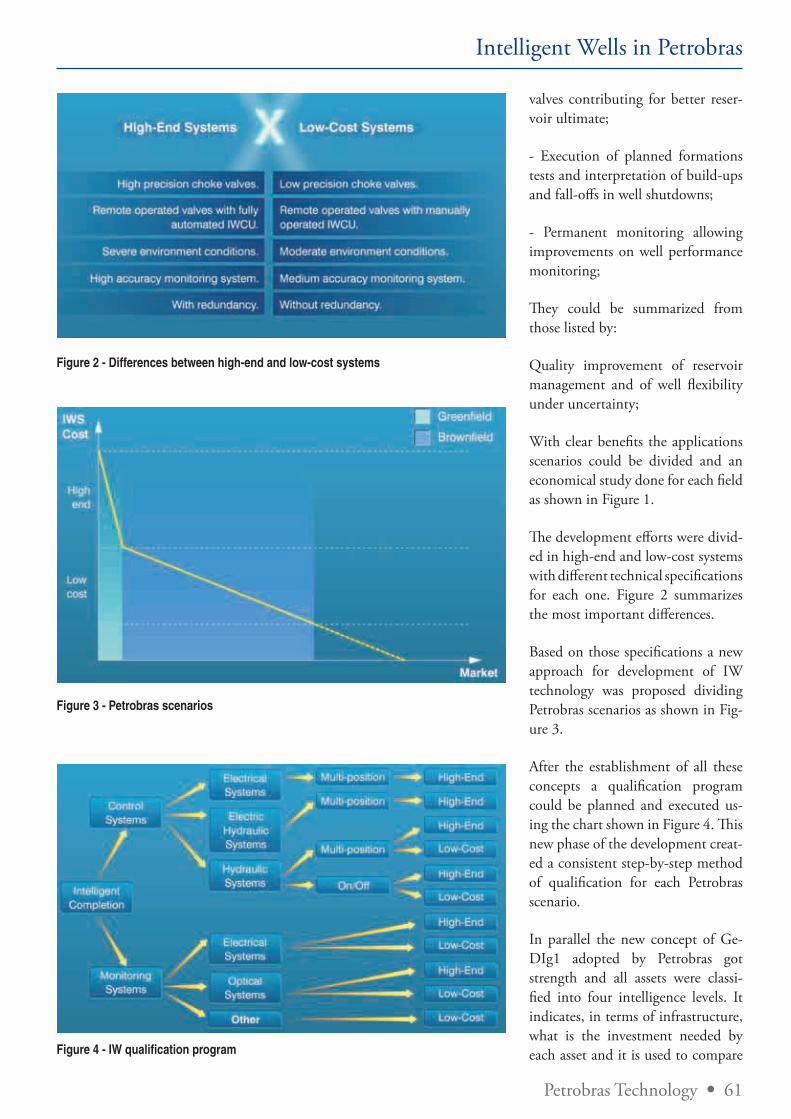
Petrobras Technology • 61
Intelligent Wells in Petrobras
Figure 2 - Differences between high-end and low-cost systems
Figure 3 - Petrobras scenarios
valves contributing for better reser-voir ultimate;
- Execution of planned formations tests and interpretation of build-ups and fall-offs in well shutdowns;
- Permanent monitoring allowing improvements on well performance monitoring;
They could be summarized from those listed by:
Quality improvement of reservoir management and of well flexibility under uncertainty;
With clear benefits the applications scenarios could be divided and an economical study done for each field as shown in Figure 1.
The development efforts were divid-ed in high-end and low-cost systems with different technical specifications for each one. Figure 2 summarizes the most important differences.
Based on those specifications a new approach for development of IW technology was proposed dividing Petrobras scenarios as shown in Fig-ure 3.
After the establishment of all these concepts a qualification program could be planned and executed us-ing the chart shown in Figure 4. This new phase of the development creat-ed a consistent step-by-step method of qualification for each Petrobras scenario.
In parallel the new concept of Ge-DIg1 adopted by Petrobras got strength and all assets were classi-fied into four intelligence levels. It indicates, in terms of infrastructure, what is the investment needed by each asset and it is used to compare Figure 4 - IW qualification program
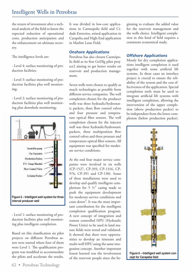
62 • Petrobras Technology
Intelligent Wells in Petrobras
the return of investment after a tech-nical analysis of the field to know the expected reduction of operational costs, production anticipation and the enhancement on ultimate recov-ery.
The intelligence levels are:
- Level 4: surface monitoring of pro-duction facilities;
- Level 3: surface monitoring of pro-duction facilities plus well monitor-ing;
- Level 2: surface monitoring of pro-duction facilities plus well monitor-ing plus downhole monitoring;
Figure 5 – Intelligent well system for three interval producer well
- Level 1: surface monitoring of pro-duction facilities plus well monitor-ing plus intelligent completion.
Based on this classification six pilot projects on different Petrobras as-sets were started where four of them were Level 1. The qualification pro-gram was modified to accommodate the pilots and accelerate the results.
It was divided in low-cost applica-tions in Carmopolis field and Ci-dade Entrerios, mixed application in Carapeba and High-End application in Marlim Leste Field.
Onshore ApplicationsPetrobras has also chosen Carmópo-lis field as its first GeDIg pilot proj-ect2 aiming to get better results on reservoir and production manage-ment.
Seven wells were chosen to qualify as much technologies as possible from different service companies. The well completion chosen for the producer wells was three hydraulic/hydrostat-ic packers, three flow control valves and four pressure and tempera-ture optical fiber sensors. The well completion chosen for the injector well was three hydraulic/hydrostatic packers, three multiposition flow control valves and three pressure and temperature optical fiber sensors. All equipment was specified for moder-ate service conditions.
At the end four major service com-panies were involved in six wells (CP-1527, CP-393, CP-1316, CP-976, CP-391 and CP-130). Some of these installations were used to develop and qualify intelligent com-pletions for 5 ½” casing made to push the equipment development for moderate service conditions and costs down3. It was the most impor-tant contribution for the intelligent completion qualification program. A new concept of integration and remote controlled HPU (Hydraulic Power Units) to be used in land ma-ture fields were tested and validated. It showed that there were opportu-nities to develop an itinerant and multi-well HPU using the same inte-gration concept. Another important lesson learned was the involvement of the reservoir people since the be-
ginning to evaluate the added value for the reservoir management and the wells choice. Intelligent comple-tion in this kind of field requires a consistent economical study.
Offshore ApplicationsMostly for dry completion applica-tions intelligent completion is used together with some artificial lift systems. In these cases an interface project is crucial to ensure the reli-ability of the system and the cost ef-fectiveness of the application. Special completion tools must be used to integrate artificial lift systems with intelligent completion, allowing the intervention of the upper comple-tion (above production packer) to be independent from the lower com-pletion (below production packer).
Figure 6 – Intelligent well system con-cept for Carapeba field
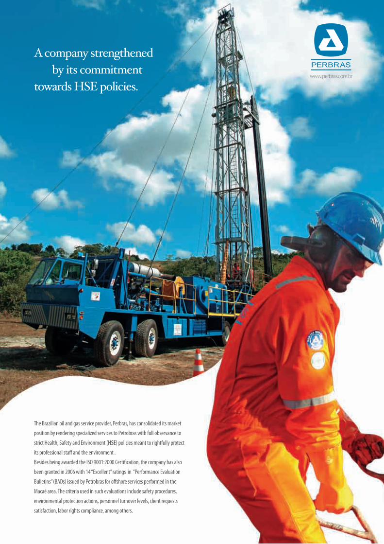
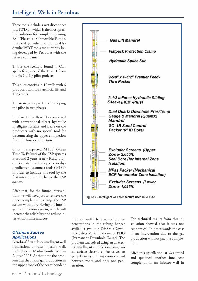
64 • Petrobras Technology
Intelligent Wells in Petrobras
These tools include a wet disconnect tool (WDT), which is the most prac-tical solution for completions using ESP (Electrical Submersible Pump). Electric-Hydraulic and Optical-Hy-draulic WDT tools are currently be-ing developed by Petrobras with the service companies.
This is the scenario found in Car-apeba field, one of the Level 1 from the six GeDIg pilot projects.
This pilot consists in 10 wells with 6 producers with ESP artificial lift and 4 injectors.
The strategy adopted was developing the pilot in two phases.
In phase 1 all wells will be completed with conventional direct hydraulic intelligent systems and ESP’s on the producers with no special tool for disconnecting the upper completion from the lower completion.
Once the expected MTTF (Mean Time To Failure) of the ESP systems is around 2 years, a new R&D proj-ect is created to develop electric-hy-draulic wet disconnect tools (WDT) in order to include this tool by the first intervention to change the ESP system.
After that, for the future interven-tions we will need just to retrieve the upper completion to change the ESP system without retrieving the intelli-gent completion system, which will increase the reliability and reduce in-tervention time and cost.
Offshore Subsea ApplicationsPetrobras' first subsea intelligent well installation, a water injector well, took place at Marlin South Field in August 2003. At that time the prob-lem was the risk of gas production in the upper zone of the correspondent
Figure 7 – Intelligent well architecture used in MLS-67
producer well. There was only three penetrations in the tubing hanger available: two for DHSV (Down-hole Safety Valve) and one for PDG (Permanent Downhole Gauge). The problem was solved using an all elec-tric intelligent completion using two subsurface electric choke valves to get selectivity and injection control between zones and only one pen-etration.
The technical results from this in-stallation showed that it was not economical. In other words the cost of an intervention due to the gas production will not pay the comple-tion.
After this installation, it was tested and qualified another intelligent completion in an injector well in

Petrobras Technology • 65
Intelligent Wells in Petrobras
Figure 8 – Intelligent well used in RO-35 , Roncador field
Roncardor field. RO-35, was located 14.5km far from FPSO Brazil and 1890m of water depth. This distance for direct hydraulic systems was not appropriated due to response time and the risk of control line plugging. Based on this, a multiplexed electro-hydraulic system was chosen for this application with a continuous vari-able choke for both zones. Due to the distance, a booster was needed to amplify the electrical signals for monitoring and control purposes. A canister was installed in the WCT (Wet Christmas Tree) to accommo-date the booster between the pro-duction facility and the well.
RO-35 was a complicated interven-tion even though there was success for the intelligent completion it was not so for the well. After the frac-pack job, the pac valve could not be
opened and the upper zone could not be injected.
This problem still remains and an in-tervention will be made to solve the problem. The most important lesson learned from this installation was the need for a multidisciplinary team to revise the completion integration to avoid misunderstandings.
Due to a specific need another well in Bicudo field was completed us-ing intelligent well technology. It was expected in BC-21 premature water production in the lower pay zone and an economical evaluation proved that without a need for a res-ervoir intervention this well was via-ble. Today it is an example for use in intelligent completion in marginal wells.
Marlin Leste field was chosen recent-ly as a new GeDIg pilot. Even though the intelligent wells there have been proposed to get well flexibility to control WOR/GOR it is also expect-ing an increase on reservoir ultimate recovery due to intelligent comple-tion. An optimization algorithm for the valves position during the reservoir life cycle developed specifi-cally to this application showed this benefit. There will be five producers equipped with electric/hydraulic in-telligent completion. All intelligent wells are equipped with two valves and two pressure and temperature gauges and due to restrictions on tubing hanger/WCT penetrations there are also a hydraulic multiplex-er. After this deployment it will the first GeDIg level 1 in a subsea envi-ronment of Petrobras.
Lessons learnedInfinite variable valves are not worth their cost.
Figure 9 - Proposed Marlin Leste intel-ligent well
66 • Petrobras Technology
well system creates a flexibility that achieves technical and economical needs for each project.
The moderate service conditions required by Petrobras effectively re-duced costs of the completion equip-ment, although it is still high.
Intelligent well system provides tools to increase ultimate recovery and provide more precise diagnostics of failures in equipment and produc-tion processes.
GeDIg pilots are the appropriate application to evaluate the value of intelligent completion.
References1. SILVA JR, M. F. et al. Technolo-gies trials of Intelligent Field imple-mentation in Carmópolis Field. In: SPE ATCE, 2005, Dallas Oct 9-12 (SPE 95917).
2. OPTICAL Sensing Systems, Weatherford 2006.
3. PEREIRA PINTO, H. L. C et al. Integrated Multi-Zone Low Cost Intelligent Completion for Ma-ture Fields. In: Intelligent Energy 2006, Amsterdam April 11-13 (SPE 99948).
Intelligent Wells in Petrobras
Strong standards for subsea equip-ment and intelligent wells suppliers might be used;
The most potential benefit of intel-ligent use is in field development plan phase;
WDT (Wet Disconnect Tool) might be used to guarantee independency of the upper completion;
In wells equipped with ESP (Elec-tric Submersible Pump) and SESP (Subsea Electric Submersible Pump) intelligent completion is not eco-nomical;
Technical Specifications for intelli-gent completions might avoid pre-defined components;
Expected application demand error (eg.: full electric system)
SWOT analysis
StrengthsLow cost flow control systems for moderate service conditions;
Fiber Optic Sensors for moderate service conditions applicable for ar-tificial lift optimization and reservoir surveillance.
Carmópolis GeDIg Pilot Proj-ect (planning and excution in 18 months)
WeaknessLack of integrated solutions
Wet Disconnect Tools for electric/hydraulic or optic/hydraulic intelli-gent completions
Even for moderate conditions cost is issue for land mature field applica-tions
OpportunitiesMake single or multiple secondary or marginal targets economical;
Itinerant or remote surface control systems for multiple well;
Remote well operation (subsea to shore concept);
Number of wells in the field devel-opment plan;
Integrate transient analysis and res-ervoir management in real time;
ThreatsEquipment over-specifications;
Does not take full advantage of the technology (> cost/benefit);
Inversion on price x demand curve motivated by a strong technology interest and by reaching over pro-duction capacity;
Lower reliability due to new un-known suppliers;
ConclusionsIntelligent completion allows quality improvement on reservoir manage-ment due to the real time subsurface production parameters monitoring and control.
The multiple technologies used in the development of an intelligent
The moderate service conditions required by Petrobras effectively reduced costs of the completion equipment, although it is still high.
Intelligent well system provides tools to increase ultimate recovery and provide more precise diagnostics of failures in equipment and production processes.
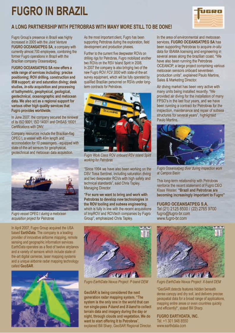
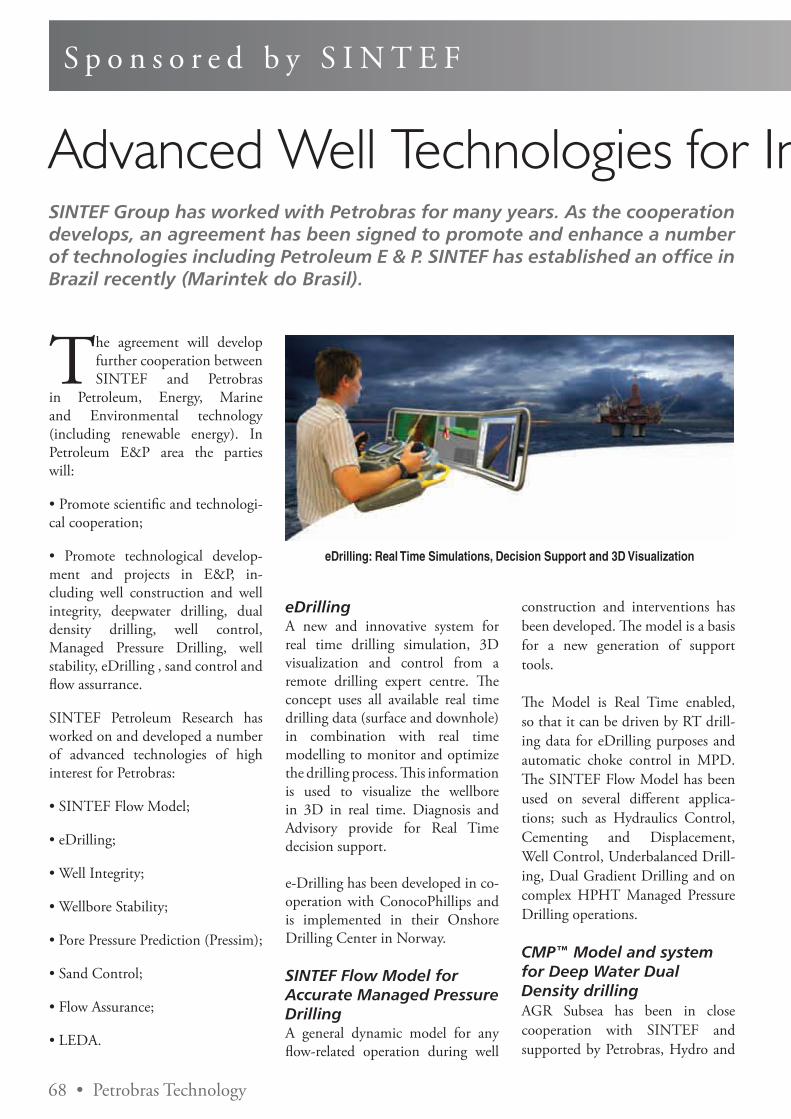
S p o n s o r e d b y S I N T E F
SINTEF Group has worked with Petrobras for many years. As the cooperation develops, an agreement has been signed to promote and enhance a number of technologies including Petroleum E & P. SINTEF has established an office in Brazil recently (Marintek do Brasil).
The agreement will develop further cooperation between SINTEF and Petrobras
in Petroleum, Energy, Marine and Environmental technology (including renewable energy). In Petroleum E&P area the parties will:
• Promote scientific and technologi-cal cooperation;
• Promote technological develop-ment and projects in E&P, in-cluding well construction and well integrity, deepwater drilling, dual density drilling, well control, Managed Pressure Drilling, well stability, eDrilling , sand control and flow assurrance.
SINTEF Petroleum Research has worked on and developed a number of advanced technologies of high interest for Petrobras:
• SINTEF Flow Model;
• eDrilling;
• Well Integrity;
• Wellbore Stability;
• Pore Pressure Prediction (Pressim);
• Sand Control;
• Flow Assurance;
• LEDA.
eDrillingA new and innovative system for real time drilling simulation, 3D visualization and control from a remote drilling expert centre. The concept uses all available real time drilling data (surface and downhole) in combination with real time modelling to monitor and optimize the drilling process. This information is used to visualize the wellbore in 3D in real time. Diagnosis and Advisory provide for Real Time decision support.
e-Drilling has been developed in co-operation with ConocoPhillips and is implemented in their Onshore Drilling Center in Norway.
SINTEF Flow Model for Accurate Managed Pressure DrillingA general dynamic model for any flow-related operation during well
construction and interventions has been developed. The model is a basis for a new generation of support tools.
The Model is Real Time enabled, so that it can be driven by RT drill-ing data for eDrilling purposes and automatic choke control in MPD. The SINTEF Flow Model has been used on several different applica-tions; such as Hydraulics Control, Cementing and Displacement, Well Control, Underbalanced Drill-ing, Dual Gradient Drilling and on complex HPHT Managed Pressure Drilling operations.
CMP™ Model and system for Deep Water Dual Density drillingAGR Subsea has been in close cooperation with SINTEF and supported by Petrobras, Hydro and
eDrilling: Real Time Simulations, Decision Support and 3D Visualization
Advanced Well Technologies for Increased Safety and Cost Efficiency
68 • Petrobras Technology
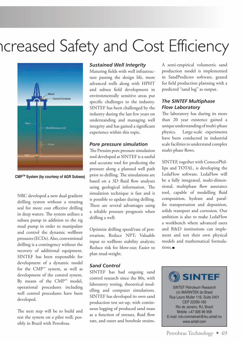
A semi-empirical volumetric sand production model is implemented in SandPredictor software, geared for fi eld production planning with a predicted “sand log” as output.
The SINTEF Multiphase Flow LaboratoryTh e laboratory has during its more than 20 year existence gained a unique understanding of multi-phase physics. Large-scale experiments have been conducted in industrial scale facilities to understand complex multi-phase fl ows.
SINTEF, together with ConocoPhil-lips and TOTAL, is developing the LedaFlow software. LedaFlow will be a fully integrated, multi-dimen-sional, multiphase fl ow assurance tool, capable of modelling fl uid composition, hydrate and paraf-fi n transportation and deposition, solids transport and corrosion. Our ambition is also to make LedaFlow a workbench where advanced users and R&D institutions can imple-ment and test their own physical models and mathematical formula-tions.
Advanced Well Technologies for Increased Safety and Cost Efficiency
NRC developed a new dual gradient drilling system without a rotating seal for more cost eff ective drilling in deep waters. Th e system utilizes a subsea pump in addition to the rig mud pump in order to manipulate and control the dynamic wellbore pressures (ECDs). Also, conventional drilling is a contingency without the recovery of additional equipment. SINTEF has been responsible for development of a dynamic model for the CMP™ system, as well as development of the control system. By means of the CMP™ model, operational procedures including well control procedures have been developed.
Th e next step will be to build and test the system on a pilot well; pos-sibly in Brazil with Petrobras.
CMPTM System (by courtesy of AGR Subsea)
Sustained Well IntegrityMaturing fi elds with well infrastruc-ture passing the design life, more advanced wells along with HPHT and subsea fi eld development in environmentally sensitive areas put specifi c challenges to the industry. SINTEF has been challenged by the industry during the last few years on understanding and managing well integrity and has gained a signifi cant experience within this topic.
Pore pressure simulationTh e Pressim pore pressure simulation tool developed at SINTEF is a useful and accurate tool for predicting the pressure along a planned well path prior to drilling. Th e simulations are based on a 3D fl uid fl ow analyses using geological information. Th e simulation technique is fast and it is possible to update during drilling. Th ere are several advantages using a reliable pressure prognosis when drilling a well:
Optimize drilling speed/rate of pen-etration; Reduce NPT; Valuable input to wellbore stability analysis; Reduce risk for blow-out; Easier to plan mud-weight.
Sand ControlSINTEF has had ongoing sand control research since the 80s, with laboratory testing, theoretical mod-elling and computer simulations. SINTEF has developed its own sand production test set-up, with contin-uous logging of produced sand mass as a function of stresses, fl uid fl ow rate, and outer and borehole strains.
Petrobras Technology • 69
SINTEF Petroleum Researchc/o MARINTEK do Brasil
Rua Lauro Muller 116, Suite 2401CEP 22290-160
Rio de Janeiro, RJ, BrazilMobile: +47 926 96 958
E-mail: [email protected]