pesticide handling areas and biobeds a presentation for farmers, operators and advisers ver1.4...
TRANSCRIPT
Pesticide Handling Areas and Biobeds
A presentation for farmers, operators and
advisers
Ver1.4
Developed for the Crop Protection Association and Agricultural Industries Confederation by ADAS. The assistance of the Environment Agency, SEPA & the Farming Unions is also acknowledged. This is part of the voluntary initiative to minimise the environmental impact of pesticides
CAUTION
Seek Regulatory Advice Before Building a Biobed
Contact the Environment Agency's Agricultural Waste Line for advice
0845 6033113

2
Contents
Main issues Options for Pesticide Handling AreasSizingManagement and operationLikely costsFinal water disposal
3
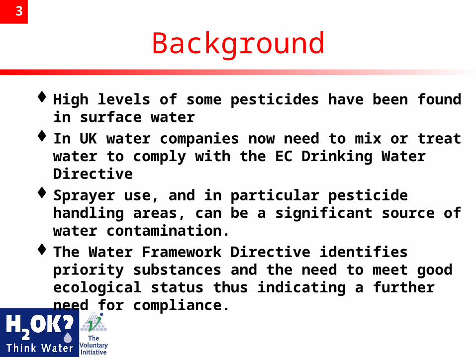
Background
High levels of some pesticides have been found in surface water
In UK water companies now need to mix or treat water to comply with the EC Drinking Water Directive
Sprayer use, and in particular pesticide handling areas, can be a significant source of water contamination.
The Water Framework Directive identifies priority substances and the need to meet good ecological status thus indicating a further need for compliance.
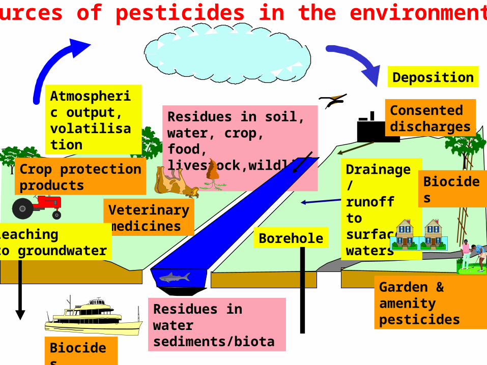
Sources of pesticides in the environment
Biocides
Atmospheric output,volatilisation
Deposition
Garden & amenity pesticides
Borehole
Residues in water sediments/biota
Residues in soil, water, crop, food, livestock,wildlife
Veterinarymedicines
Sources of pesticides in the environment
Drainage/runoff to surfacewaters
Biocides
Leachingto groundwater
Crop protectionproducts
Consenteddischarges
5
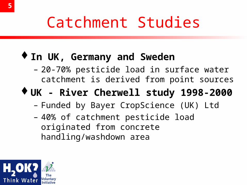
Catchment Studies
In UK, Germany and Sweden– 20-70% pesticide load in surface water
catchment is derived from point sources
UK - River Cherwell study 1998-2000– Funded by Bayer CropScience (UK) Ltd– 40% of catchment pesticide load originated
from concrete handling/washdown area
6
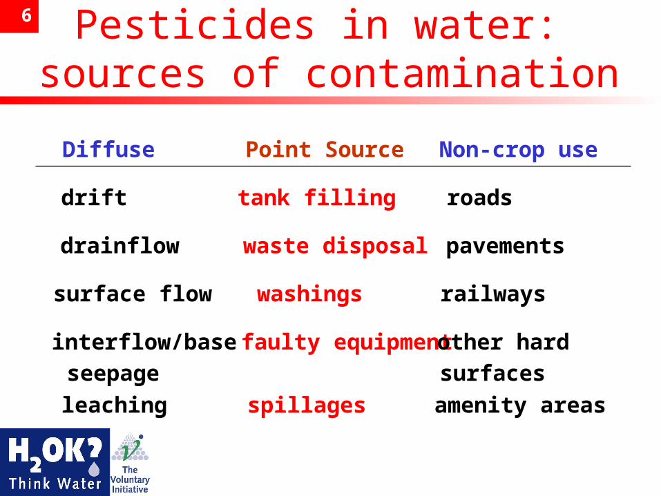
Pesticides in water
Pesticides in water: sources of contamination
Diffuse Point Source Non-crop use
drift tank filling roads
drainflow waste disposal pavements
surface flow washings railways
interflow/baseseepage
faulty equipmentother hardsurfaces
leaching spillages amenity areas
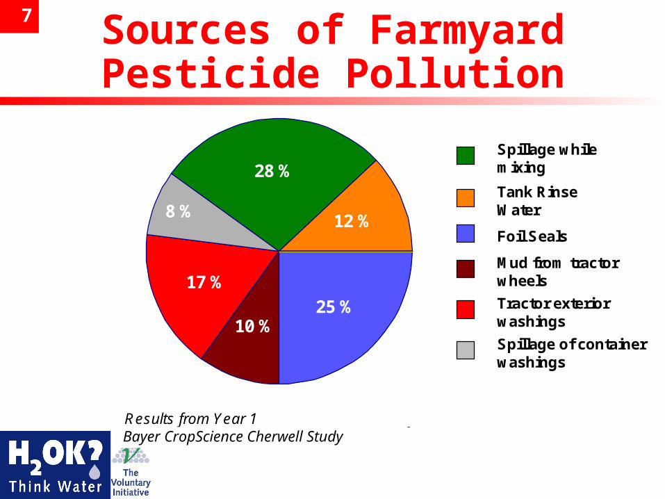
7 Sources of FarmyardPesticide Pollution
17 %
8 %
28 %
12 %
10 %25 %
Mud from tractorwheels
Tractor exteriorwashings
Spillage of containerwashings
Spillage whilemixing
Tank RinseWater
Foil Seals
Results from Year 1 Aventis Cherwell StudyBayer CropScience Cherwell Study
8
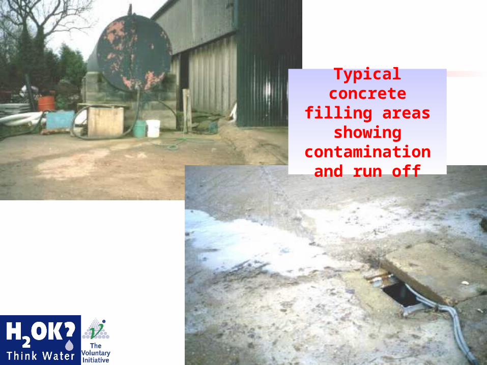
Concrete Filling Areas
Typical concrete filling areas showing contamination
and run off
9
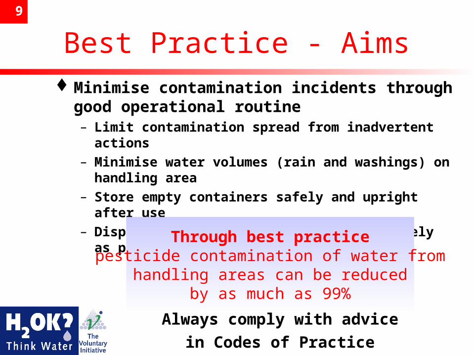
Best Practice - AimsMinimise contamination incidents through
good operational routine– Limit contamination spread from inadvertent
actions– Minimise water volumes (rain and washings) on
handling area– Store empty containers safely and upright after
use– Dispose of containers frequently and safely as
permitted.Through best practice
pesticide contamination of water fromhandling areas can be reduced
by as much as 99%
Always comply with advice
in Codes of Practice
10
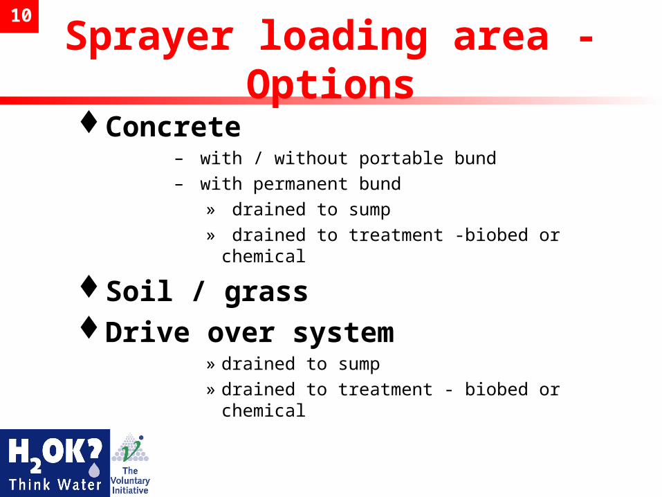
Sprayer loading area - Options
Concrete – with / without portable bund– with permanent bund
» drained to sump» drained to treatment -biobed or chemical
Soil / grassDrive over system
» drained to sump» drained to treatment - biobed or chemical
11
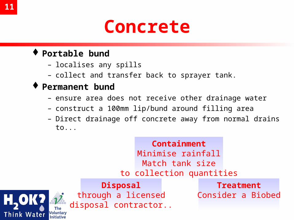
ConcretePortable bund
– localises any spills– collect and transfer back to sprayer tank.
Permanent bund – ensure area does not receive other drainage water– construct a 100mm lip/bund around filling area– Direct drainage off concrete away from normal drains to...
ContainmentMinimise rainfallMatch tank size
to collection quantities
Disposalthrough a licensed
disposal contractor..
TreatmentConsider a Biobed
12
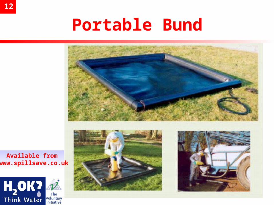
Portable Bund
Available from www.spillsave.co.uk
13
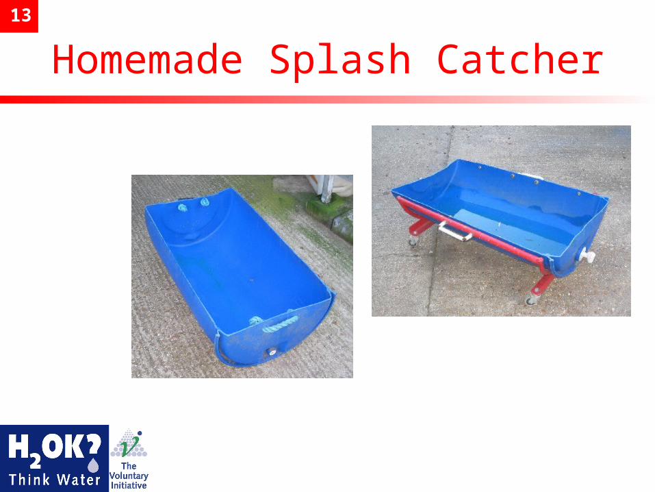
Homemade Splash Catcher
14
Soil / GrassWhere site allows, filling the sprayer over a
permeable surface can be useful. Natural breakdown of the pesticides is achieved by microbial action in the soil
BUT– Site >10m away from field drains and
watercourses;>50m from springs, wells and boreholes– Prevent soil compaction by use of drive over grid or
hardcore– May need to move site around periodically if compaction
occurs– Avoid use on heavy clay
15
Handling Area - with a biobed
A well planned, designed and operated area linked to a biobed will allow pesticides to be retained and degraded by a considerable amount (10,000 -100,000 fold reduction)
A pesticide handling area (mixing and sprayer loading only) may be linked to a biobed without the need for a Groundwater Authorisation from the local environment agency.(See sprayer washing note on next slide)
16
Sprayer Washdown - Special note
Best Practice for tank washings and sprayer exterior surfaces is to carry this out in the field– Any washings should be discharged onto the
previously sprayed cropped area– Observing maximum dose for that area– Follow Statutory (Green) Code advice
If sprayer washdown is intended at the pesticide handlingarea with disposal to land elsewhere, unless a lined
biobed is being used, a Groundwater Authorisation must be obtained from the your local environment agency
17
Biobeds and The Law EA and SEPA support Lined Biobeds as
significant improvement over current practice
NEW Regulatory advice for England and Wales from EA – Groundwater Authorisation (GWA) not required for
lined Biobed– Water from lined Biobed can be “irrigated” or re-
used without GWA – Site will have to be registered with EA in the future
but is expected that registration will be free and can be done on line
– Scotland check with SEPA– Northern Ireland check with EHS
Biobeds
Design, Construction, Use and Maintenance
19
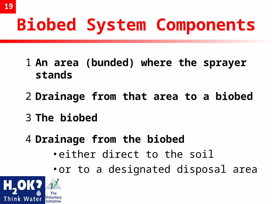
Biobed System Components
1 An area (bunded) where the sprayer stands
2 Drainage from that area to a biobed
3 The biobed
4 Drainage from the biobed•either direct to the soil•or to a designated disposal area
20
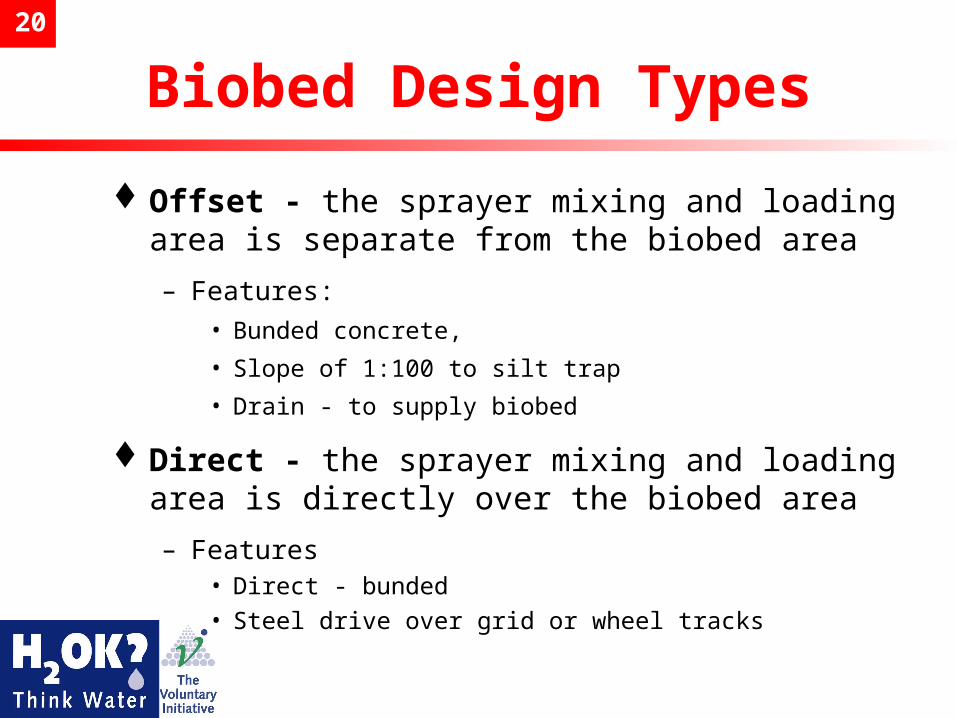
Biobed Design Types
Offset - the sprayer mixing and loading area is separate from the biobed area
– Features:
• Bunded concrete,
• Slope of 1:100 to silt trap
• Drain - to supply biobed
Direct - the sprayer mixing and loading area is directly over the biobed area
– Features• Direct - bunded
• Steel drive over grid or wheel tracks

21Pesticide Handling Areas
linked to BiobedsWhat do the designs look
like?
– Offset - A separate area, bunded concrete, where the sprayer stands and any liquids drain to a biobed
– Direct - A drive over grid all liquids drain directly to the biobed below the grid.
Both designs may use lined or unlined biobeds; but only lined biobeds are suitable for washdown
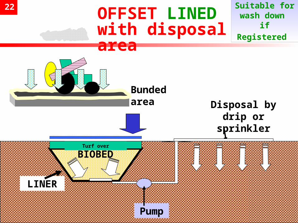
22
Offset Biobed with Disposal Area
BIOBED
LINER
Bunded area
OFFSET LINEDwith disposal area
Turf over
Disposal by drip or
sprinkler
Pump
Suitable for wash down if Registered
23
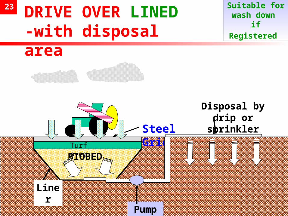
Direct Lined Biobed with drive over
BIOBED
DRIVE OVER LINED-with disposal area
Turf over
Steel Grid
Pump
Disposal by drip or
sprinkler
Liner
Suitable for wash down if Registered
24
Location.. Location.. Location..
Close to sprayer water filling point, chemical store and electricity supply
Away from other traffic / access routes, footpaths etc.
Avoiding collecting extra rainfall - check yard contours, other drain routes and overflow issues
Separate from other drains / watercourses (>10m;>50m)
Groundwater Risks?

25
Pesticide Handling Area Dimensions
300 mm
100 mm Drain via silt trap to pump
chamber
W
L
W = Sprayer transport width + 2 m
L = Sprayer length + 1.5 m
Concrete pad
Bund
26
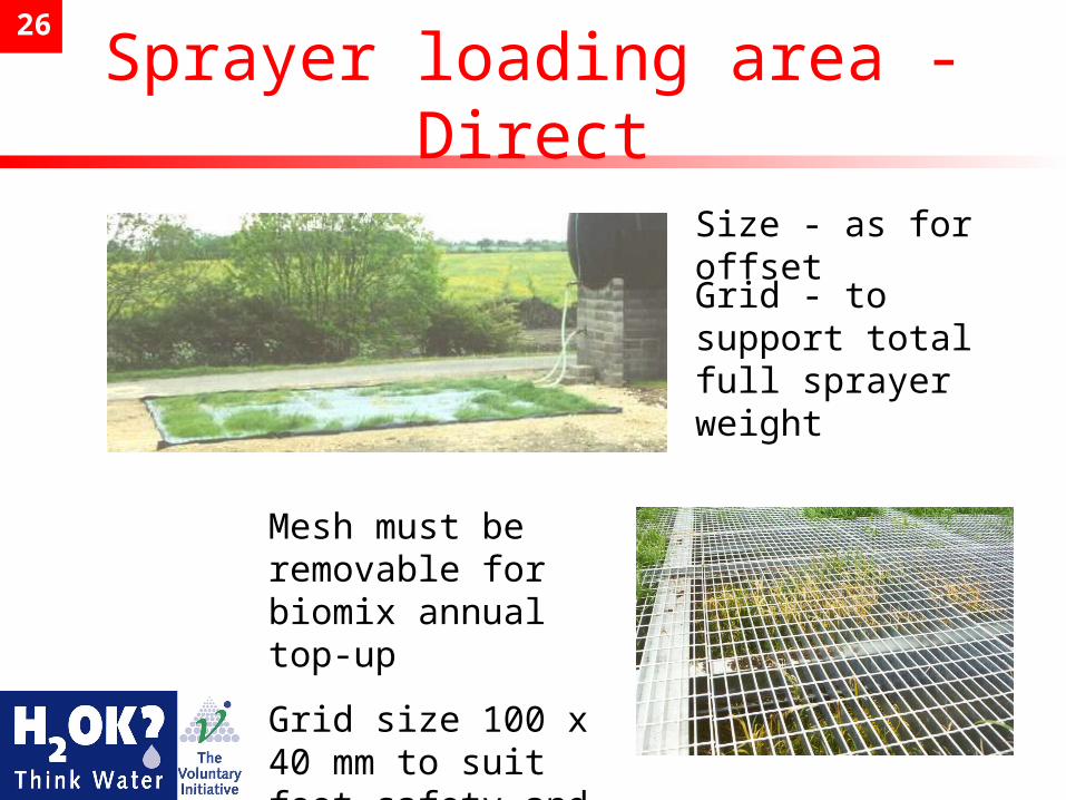
Sprayer loading area - Direct
Size - as for offset
Grid - to support total full sprayer weight
Mesh must be removable for biomix annual top-up
Grid size 100 x 40 mm to suit foot safety and soil/mud flow through
27
The Biobed -What is it?
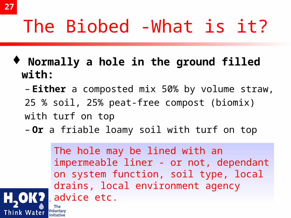
Normally a hole in the ground filled with:– Either a composted mix 50% by volume straw,25 % soil, 25% peat-free compost (biomix)with turf on top– Or a friable loamy soil with turf on top
The hole may be lined with an impermeable liner - or not, dependant on system function, soil type, local drains, local environment agency advice etc.
28
Biobeds - Function, location and size
How do they work?– By locking up the pesticides and then providing
conditions for enhanced microbial degradation of the active ingredients over time
Location– A biobed can be sited independently from the loading
area, taking account of local drainage, access, groundwater risks, contours etc.
Size– Where a 24 m, 3000 l sprayer has been used then 5 x 4 x 1 m deep bed has been satisfactory, though
local rainfall and frequency of use will influence final size.
Biobeds should always be at least 1m deep
29
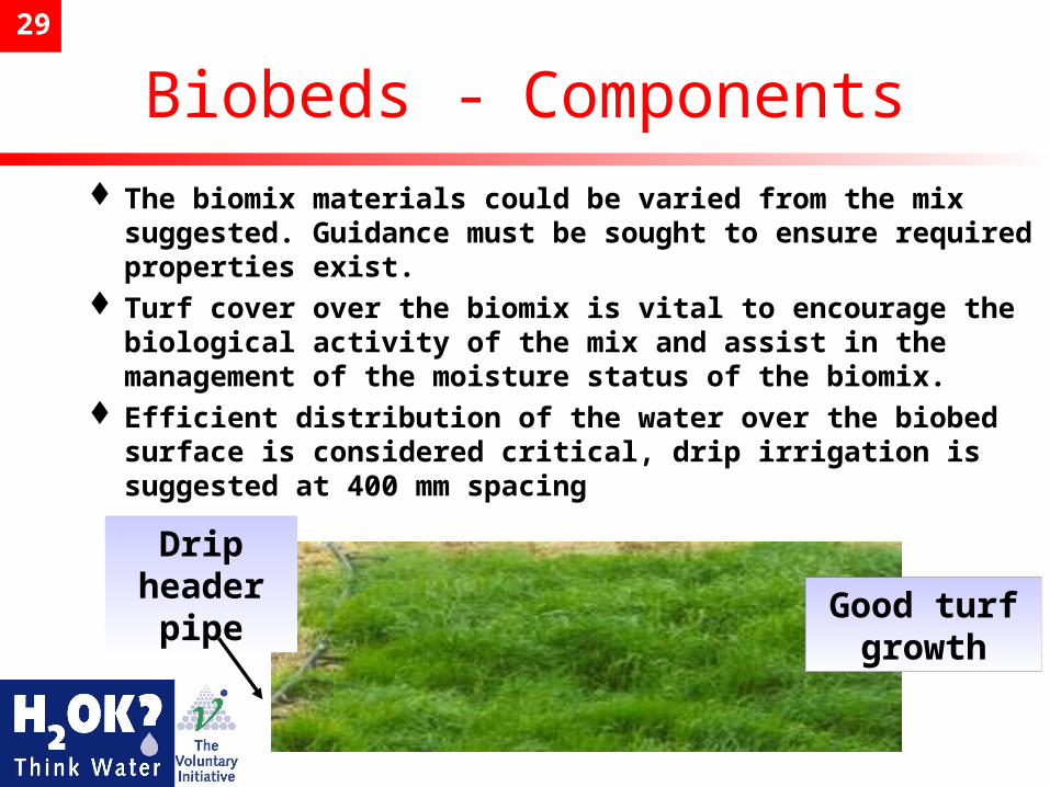
Biobeds - Components The biomix materials could be varied from the mix
suggested. Guidance must be sought to ensure required properties exist.
Turf cover over the biomix is vital to encourage the biological activity of the mix and assist in the management of the moisture status of the biomix.
Efficient distribution of the water over the biobed surface is considered critical, drip irrigation is suggested at 400 mm spacing
Drip header
pipeGood turf growth
30
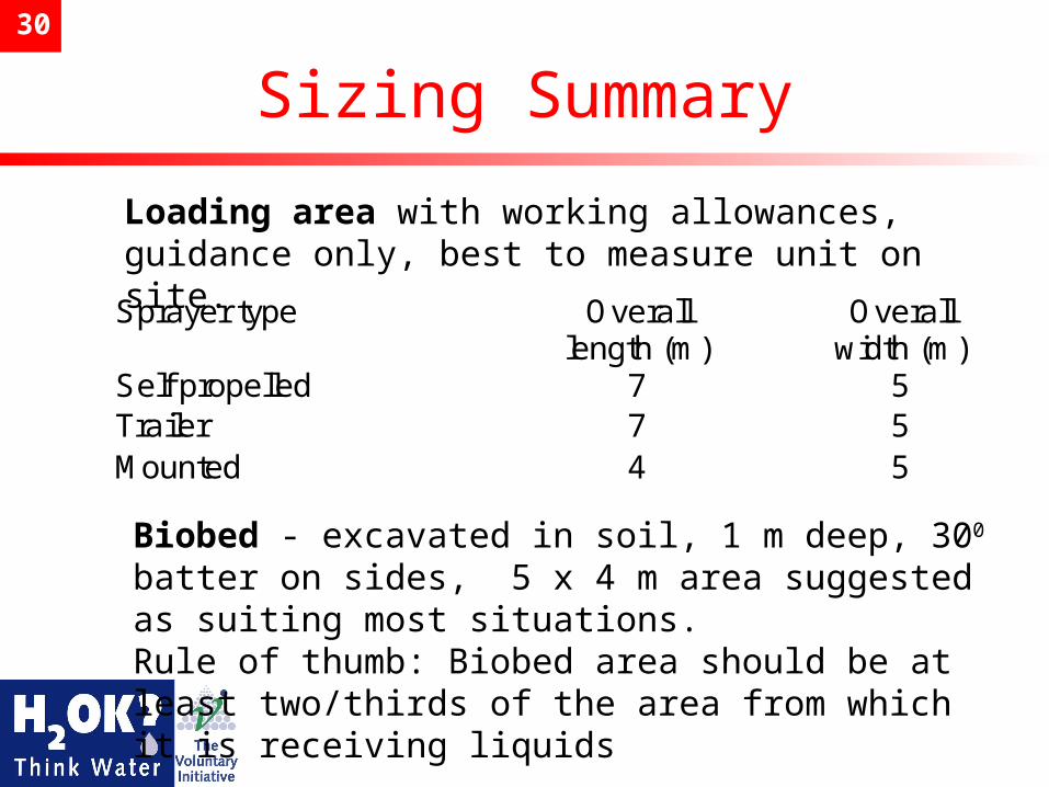
Sizing Summary
Sprayer type Overalllength (m)
Overallwidth (m)
Self propelled 7 5Trailer 7 5Mounted 4 5
Loading area with working allowances, guidance only, best to measure unit on site.
Biobed - excavated in soil, 1 m deep, 300 batter on sides, 5 x 4 m area suggested as suiting most situations.Rule of thumb: Biobed area should be at least two/thirds of the area from which it is receiving liquids
31
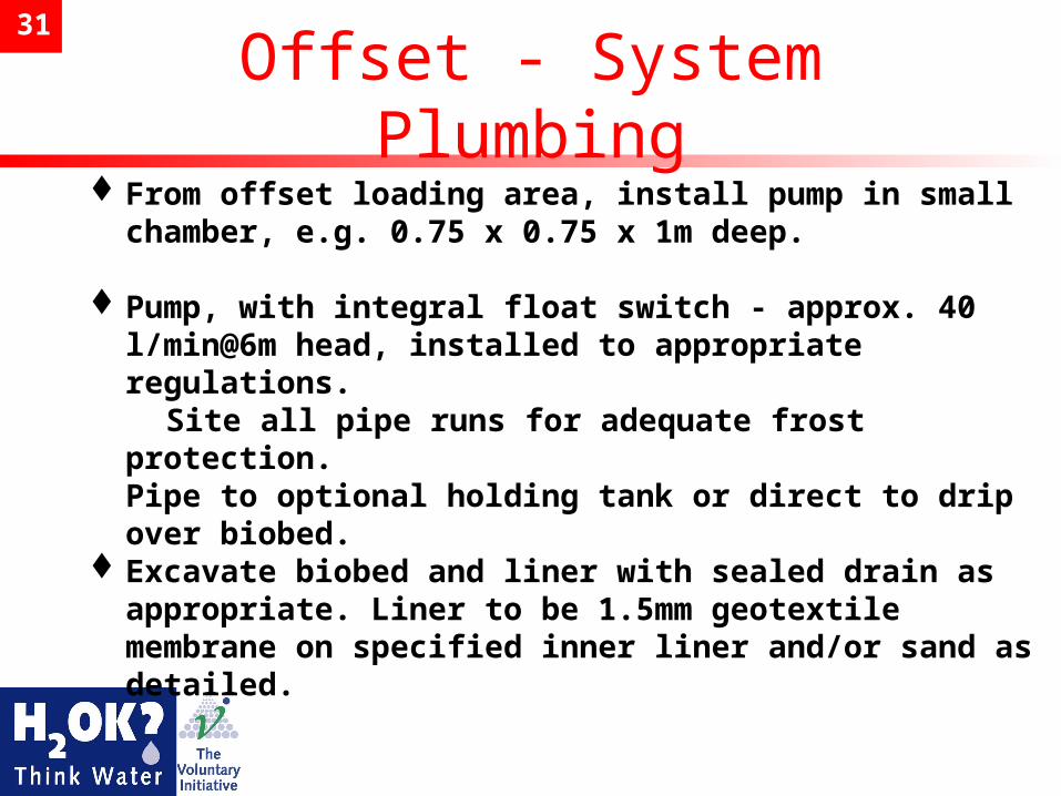
Offset - System PlumbingFrom offset loading area, install pump in small
chamber, e.g. 0.75 x 0.75 x 1m deep.
Pump, with integral float switch - approx. 40 l/min@6m head, installed to appropriate regulations.
Site all pipe runs for adequate frost protection.Pipe to optional holding tank or direct to drip over biobed.
Excavate biobed and liner with sealed drain as appropriate. Liner to be 1.5mm geotextile membrane on specified inner liner and/or sand as detailed.
32
Direct System Design
Design and construct grid to adequately support spray vehicle and ensure safe operator use.– Operator should be kept off biobed surface for
functional and safety reasons. – Allow for grid to be removed in sections for annual
biomix top-up.Construct foundations, as appropriate,
avoiding support on biobed liner if used.Excavate biobed and liner with sealed
drain as appropriate.Liner to be 1.5 mm geotextile membrane
on specified inner liner and/or sand as detailed.See further biobed installation notes
33
Biobed - Installation 1Biobed can either be a biomix - straw, soil and
peat-free compost, or loamy soilBiobed will need lining where washdown is to be
practised (with Groundwater Authorisation)Lining must be sealed to outlet drain effectively
with coarse filter over drain inlet, e.g. 6 mm mesh
Where unlined, ensure that subsoil is uncompacted
Lining should overlap top of side batter by approx. 300 mm thereby preventing unnecessary rainfall reaching biobed
34
Biobed Installation - 2Direct drain to optional tank or small pump
chamber as before, or to pump to final disposal area
Biomix must be composted for 4-6 weeks before use and evenly loaded into hole. Overfill hole to allow for early sinkage
Turf should be laid at time of filling to encourage growth. Turf does not need to be high quality and is laid over the surface of the biomix, watering early to encourage growth
Install drip irrigation, hard hose type best, laid onto the biobed turf surface as well as the final disposal area, lightly anchor drip lines
Test pump system before use
35
Biobed Management - short term
Biobed irrigation will maintain regular watering of turf and thus control biomix moisture condition
Grass growth will encourage moisture use and thus evapo-transpiration from biobed
Check weekly for condition and function. Investigate any tendency for waterlogging.
Any foliage cut from biobed turf cover to be mulched over biobed area
36
Biobed management - long term 1
Where biomix is used, material will degrade and level sinks by approx. 300 mm per year
Biomix top-up annually necessary. Dependent on turf growth, turf may be peeled back (with adequate operator protection) and new mix added to restore level, replace turf.
Soil based systems probably will not ‘shrink’ as fast.
Check irrigation function
37
Biomix material in the hole will probably have a life of 6 -8 years before replacement or recycling
Removal of biomix should be done carefully (with appropriate operator protection) to a concrete area for further composting for one year. Research suggests any pesticides remaining are fully degraded in that period.
Drainage from this area should be preferentially routed to the replenished biobed.
Final disposal of the spent biomix material must be in accordance with advice from local environment agency.
Biobed management - long term 2
38
Water distribution - disposal area
Where drip irrigation used, lay hard hose pipes at 400 mm spacing with drippers at around 1.5 l/h flow rate.– 1-1.5 running hours per day applies 2-4 mm
of water, dependant on equipment used.
Set controls, e.g. level switch and any timers, to achieve this, allowing for override in intense rainfall – buffer available from optional tank if installed
39
Typical Costs - OffsetSprayer loading area - depends on
whether adequate concrete present with bund added or new material - range £300 - £850
Each chamber £140, pump £60Biobed, excavation and materials £500Liner, if needed with drain £1000Drip irrigation to biobed and final
disposal, depends on areas £200- £400

40
Typical Costs - Direct
Sprayer vehicle grid - range £2000 - £5000
Biobed, excavation and materials / foundations £800
Liner, if needed, with drain £1000Each chamber £140, pump £60Drip irrigation to final disposal,
depends on area £300
41
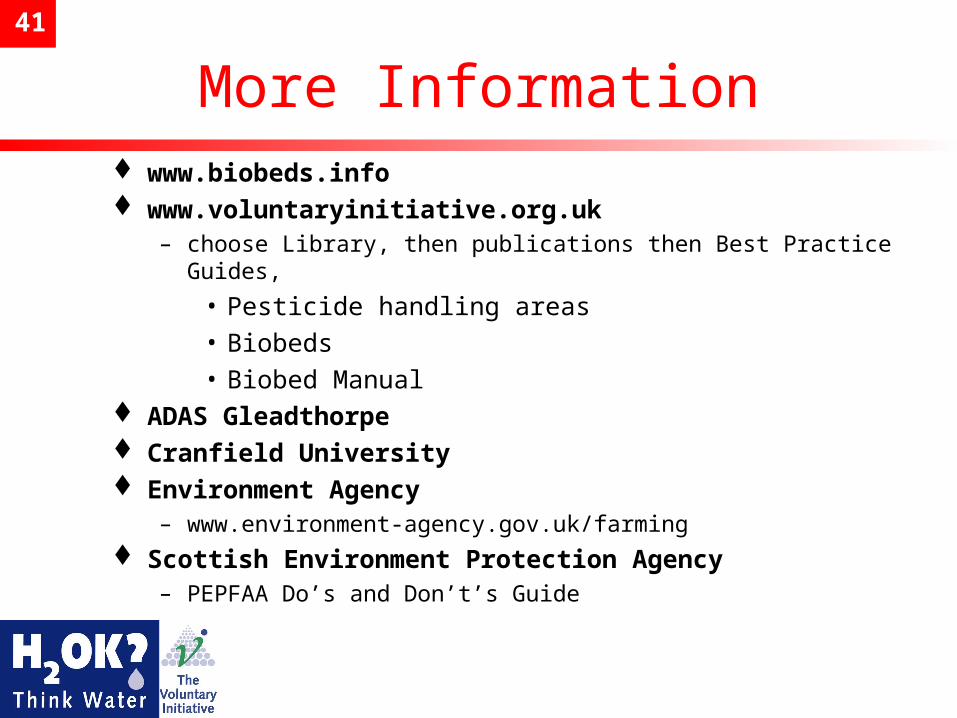
More Information www.biobeds.info www.voluntaryinitiative.org.uk
– choose Library, then publications then Best Practice Guides,
• Pesticide handling areas • Biobeds• Biobed Manual
ADAS Gleadthorpe Cranfield University Environment Agency
– www.environment-agency.gov.uk/farming
Scottish Environment Protection Agency– PEPFAA Do’s and Don’t’s Guide
42
CPD
BASIS CPD Points AP/032/034/d = 1APNRoSO CPD Points N0340530c = 1AP
Practical Simple Solutions
Protecting the Environment