personal computer data acquisition a/d...
TRANSCRIPT

2002 Microchip Technology Inc. DS21478B-page 1
TC835
Features
• Upgrade of Pin-Compatible TC7135, ICL7135
• 200kHz Operation
• Single 5V Operation With TC7660
• Multiplexed BCD Data Output
• UART and Microprocessor Interface
• Control Outputs for Auto-Ranging
• Input Sensitivity: 100µV
• No Sample and Hold Required
Applications
• Personal Computer Data Acquisition
• Scales, Panel Meters, Process Controls
• HP-IL Bus Instrumentation
Device Selection Table
General Description
The TC835 is a low power, 4-1/2 digit (0.005%resolution), BCD analog to digital converter (ADC) thathas been characterized for 200kHz clock rate opera-tion. The five conversions per second rate is nearlytwice as fast as the ICL7135 or TC7135. The TC835,like the TC7135, does not use the external diode resis-tor rollover error compensation circuits required by theICL7135.
The multiplexed BCD data output is perfect for interfac-ing to personal computers. The low cost, greater than14-bit high-resolution and 100µV sensitivity makes theTC835 exceptionally cost-effective.
Microprocessor-based data acquisition systems aresupported by the BUSY and STROBE outputs, alongwith the RUN/HOLD input of the TC835. TheOVERRANGE, UNDERRANGE, BUSY and RUN/HOLD control functions, plus multiplexed BCD dataoutputs, make the TC835 the ideal converter for µP-based scales, measurement systems and intelligentpanel meters.
The TC835 interfaces with full function LCD and LEDdisplay decoder/drivers. The UNDERRANGE andOVERRANGE outputs may be used to implement anauto-ranging scheme or special display functions.
Part Number Package Temperature Range
TC835CBU 64-PinPQFP 0°C to +70°CTC835CKW 44-PinPQFP 0°C to +70°CTC835CPI 28-Pin PDIP 0°C to +70°CNote: Tape and Reel available for 44-Pin PQFP
package.
Personal Computer Data Acquisition A/D Converter

TC835
DS21478B-page 2 2002 Microchip Technology Inc.
Package Type
NOTES: 1. NC = No internal connection.2. Pins 9, 25, 40 and 56 are connected to the die substrate. The potential at these pins is approximately V+. No external connections should be made.
64-Pin PQFP
63
4
3
2
1
16
15
14
10
9
8
7
6
5
12
11
40
41
42
43
44
45
46
34
35
36
37
38
39
48
33
17 18 19 20 21 22 23 24 25 26 27 28 29 30 31
61 60 59 58 57 56 55 54 53 52 51 50 4964
TC835CBU
INT
OU
T
NC
AZ
IN V+
NC
+IN
PU
T
NC
BU
FF
OU
T
BU
F C
AP
–
NC
SU
B
BU
F C
AP
+
NC
–IN
PU
T
NC
NC
NC
NC
NC
NC
D1
DG
ND
PO
L
SU
B
CLK
IN
BU
SY
D2
32
NC
62
NC
13
47
NC
NC
NC
NC
NC
NC
NC
NC
NC
OVERRANGE
UNDERRANGE
SUB
V–
REF IN
ANALOG COM
NC
NC
D3
NC
NC
NC
NC
D4
B3
B4
B2
SUB
B1
D5
NC
NC NC
NC
ST
RO
BE
RU
N/H
OLD
TC835CPI
28-Pin PDIP
1
2
3
4 RUN/HOLD
5
6
7
8
9
10
11
12
13
14
28
27
26
25
24
23
22
21
20
19
18
17
16
15
STROBE
OVERRANGE
B4
D3
D2
D1 (LSD)
BUSY
CLOCK IN
POLARITY
DIGTAL GND
UNDERRANGE
B2
(LSB) B1
(MSD) D5
V+
+INPUT
–INPUT
CREF+
CREF-
BUFF OUT
AZ IN
INT OUT
ANALOGCOM
REF IN
V-
D4
B8 (MSD)
27
28
29
30
31
32
33
7
4
3
2
1
TC835CKW
12 13 14 15 17 18
44 43 42 41 39 3840
16
37 36 35 34
19 20 21 22
268
259
2410
2311
5
6
NC
NC
NC
AN
ALO
G
RE
F IN
V–
UR
OR
NC
NC
NC
NC
DGND
POLARITY
D2
NC
NC
CLK IN
NC
INT OUT
AZ IN
BUFF OUT
REF CAP–
–INPUT
+INPUT
V+
NC
NC
REF CAP+
NC
NC
(MS
D)
D5
(LS
B)
B1
B2
B4
(MS
B)
B8
D4
D3
NC
NC
D1 (LSD)
BUSY
RUN/HOLD
ST
RO
BE
44-Pin PQFP
CO
MM
ON

2002 Microchip Technology Inc. DS21478B-page 3
TC835
Typical Application
Channel 1
Channel 2
Channel 3
Channel 4
Data Bus
Control
Address Bus
R 6522 P
PA0PA1PA2
PA3PA4PA5PA6PA7CA1CA2
PB0 PB3PB2PB1
Channel Selection
1Y2Y3Y
1B2B3BS
1A2A3A
HCTS157POLORURD5B8B4B2
B1D1D2D3D4STBR/H
V+ REF CAP
BUFAZ
INT
INPUT+
VR
InputAnalog
Common
DGND
5V
REF Voltage
+15V -15V
DifferentialMultiplexer
DG529
DA
DB
WR
A1 A0 EN
5V+
-FIN
FIN
TC835

TC835
DS21478B-page 4 2002 Microchip Technology Inc.
1.0 ELECTRICALCHARACTERISTICS
Absolute Maximum Ratings*
Positive Supply Voltage......................................... +6VNegative Supply Voltage ........................................ -9VAnalog Input Voltage (Pin 9 or 10) ... V+ to V– (Note 2)Reference Input Voltage (Pin 2) ..................... V+ to V–Clock Input Voltage ........................................ 0V to V+
Operating Temperature Range................0°C to +70°CStorage Temperature Range ............. -65°C to +150°CPackage Power Dissipation (TA ≤ 70°C)
28-Pin Plastic DIP ............................ 1.14Ω44-Pin PQFP .................................... 1.00Ω64-Pin PQFP .................................... 1.14Ω
*Stresses above those listed under "Absolute Maximum Rat-ings" may cause permanent damage to the device. These arestress ratings only and functional operation of the device atthese or any other conditions above those indicated in theoperation sections of the specifications is not implied. Expo-sure to Absolute Maximum Rating conditions for extendedperiods may affect device reliability.
TC835 ELECTRICAL SPECIFICATIONS
Electrical Characteristics: TA = +25°C, FCLOCK = 200kHz, V+ = +5V, V- = -5V, unless otherwise specified.
Symbol Parameter Min Typ Max Unit Test Conditions
Analog
Display Reading with Zero Volt Input -0.0000 ±0.0000 +0.0000 Display Reading Note 3, Note 4
TCZ Zero Reading Temperature Coefficient — 0.5 2 µV/°C VIN = 0V, (Note 5)
TCFS Full-Scale Temperature Coefficient — — 5 ppm/°C VIN = 2V;(Note 5, Note 6
NL Nonlinearity Error — 0.5 1 Count Note 7
DNL Differential Linearity Error — 0.01 — LSB Note 7
Display Reading in Ratiometric Operation +0.9996 +0.9998 +1.0000 Display Reading VIN = VREF, (Note 3)
±FSE ± Full Scale Symmetry Error (Rollover Error) — 0.5 1 Count –VIN = +VIN, (Note 8)
IIN Input Leakage Current — 1 10 pA Note 4
eN Noise — 15 — µVP-P Peak to Peak Value notExceeded 95% of Time
Digital
IIL Input Low Current — 10 100 µA VIN = 0V
IIH Input High Current — 0.08 10 µA VIN = +5V
VOL Output Low Voltage — 0.2 0.4 V IOL = 1.6mA
VOH Output High Voltage;B1, B2, B4, B8, D1 –D5Busy, Polarity, Overrange,Underrange, Strobe
2.4 4.4 5 V IOH = 1mA
4.9 4.99 5 V IOH = 10µA
fCLK Clock Frequency 0 200 1200 kHz Note 10
Note 1: Functional operation is not implied.2: Limit input current to under 100 µA if input voltages exceed supply voltage.3: Full scale voltage = 2V.4: VIN = 0V.5: 0°C ≤ TA ≤ +70°C.6: External reference temperature coefficient less than 0.01ppm/°C.7: -2V ≤ VIN ≤ +2V. Error of reading from best fit straight line.8: |VIN| = 1.9959.9: Test circuit shown in Figure 1-1.10: Specification related to clock frequency range over which the TC835 correctly performs its various functions. Increased
errors result at higher operating frequencies.

2002 Microchip Technology Inc. DS21478B-page 5
TC835
Power Supply
V+ Positive Supply Voltage 4 5 6 V
V– Negative Supply Voltage -3 -5 -8 V
I+ Positive Supply Current — 1 3 mA fCLK = 0Hz
I– Negative Supply Current — 0.7 3 mA fCLK = 0Hz
PD Power Dissipation — 8.5 30 mΩ fCLK = 0Hz
TC835 ELECTRICAL SPECIFICATIONS (CONTINUED)
Electrical Characteristics: TA = +25°C, FCLOCK = 200kHz, V+ = +5V, V- = -5V, unless otherwise specified.
Symbol Parameter Min Typ Max Unit Test Conditions
Note 1: Functional operation is not implied.2: Limit input current to under 100 µA if input voltages exceed supply voltage.3: Full scale voltage = 2V.4: VIN = 0V.5: 0°C ≤ TA ≤ +70°C.6: External reference temperature coefficient less than 0.01ppm/°C.7: -2V ≤ VIN ≤ +2V. Error of reading from best fit straight line.8: |VIN| = 1.9959.9: Test circuit shown in Figure 1-1.10: Specification related to clock frequency range over which the TC835 correctly performs its various functions. Increased
errors result at higher operating frequencies.

TC835
DS21478B-page 6 2002 Microchip Technology Inc.
2.0 PIN DESCRIPTIONS
The descriptions of the pins are listed in Table 2-1.
TABLE 2-1: PIN FUNCTION TABLE
Pin Number28-Pin PDIP
Symbol Description
1 V- Negative power supply input.
2 REF IN External reference input.
3 ANALOG COMMON Reference point for REF IN.
4 INT OUT Integrator output. Integrator capacitor connection.
5 AZ IN Auto zero input. Auto zero capacitor connection.
6 BUFF OUT Analog input buffer output. Integrator resistor connection.
7 CREF- Reference capacitor input. Reference capacitor negative connection.
8 CREF+ Reference capacitor input. Reference capacitor positive connection.
9 -INPUT Analog input. Analog input negative connection.
10 +INPUT Analog input. Analog input positive connection.
11 V+ Positive power supply input.
12 D5 Digit drive output. Most Significant Digit (MSD)
13 B1 Binary Coded Decimal (BCD) output. Least Significant Bit (LSB)
14 B2 BCD output.
15 B4 BCD output.
16 B8 BCD output. Most Significant Bit (MSB)
17 D4 Digit drive output.
18 D3 Digit drive output.
19 D2 Digit drive output.
20 D1 Digit drive output. Least Significant Digit (LSD)
21 BUSY Busy output. At the beginning of the signal-integration phase, BUSY goes High andremains High until the first clock pulse after the integrator zero crossing.
22 CLOCK IN Clock input. Conversion clock connection.
23 POLARITY Polarity output. A positive input is indicated by a logic High output. The polarity output isvalid at the beginning of the reference integrate phase and remains valid until determinedduring the next conversion.
24 DGND Digital logic reference input.
25 RUN/HOLD Run / Hold input. When at a logic High, conversions are performed continuously. A logicLow holds the current data as long as the Low condition exists.
26 STROBE Strobe output. The STROBE output pulses low in the center of the digit drive outputs.
27 OVERRANGE Over range output. A logic High indicates that the analog input exceeds the full scale inputrange.
28 UNDERRANGE Under range output. A logic High indicates that the analog input is less than 9% of the fullscale input range.

2002 Microchip Technology Inc. DS21478B-page 7
TC835
3.0 DETAILED DESCRIPTION
(All Pin Designations Refer to 28-Pin DIP)
3.1 Dual Slope Conversion Principles
The TC835 is a dual slope, integrating analog to digitalconverter. An understanding of the dual slope conver-sion technique will aid in following the detailed TC835operational theory.
The conventional dual slope converter measurementcycle has two distinct phases:
1. Input signal integration
2. Reference voltage integration (de-integration)
The input signal being converted is integrated for a fixedtime period, with time being measured by counting clockpulses. An opposite polarity constant reference voltageis then integrated until the integrator output voltagereturns to zero. The reference integration time is directlyproportional to the input signal.
In a simple dual slope converter, a completeconversion requires the integrator output to "ramp-up"and "ramp-down."
A simple mathematical equation relates the input sig-nal, reference voltage and integration time:
EQUATION 3-1:
For a constant VIN:
EQUATION 3-2:
The dual slope converter accuracy is unrelated to theintegrating resistor and capacitor values, as long asthey are stable during a measurement cycle. Aninherent benefit is noise immunity. Noise spikes areintegrated, or averaged, to zero during the integrationperiods. Integrating ADCs are immune to the largeconversion errors that plague successive approxima-tion converters in high noise environments (seeFigure 3-1).
FIGURE 3-1: BASIC DUAL SLOPECONVERTER
3.2 TC835 Operational Theory
The TC835 incorporates a system zero phase andintegrator output voltage zero phase to the normal twophase dual slope measurement cycle. Reduced sys-tem errors, fewer calibration steps and a shorter over-range recovery time result.
The TC835 measurement cycle contains four phases:
1. System zero
2. Analog input signal integration
3. Reference voltage integration
4. Integrator output zero
Internal analog gate status for each phase is shown inTable 3-1.
3.2.1 SYSTEM ZERO
During this phase, errors due to buffer, integrator andcomparator offset voltages are compensated for bycharging CAZ (auto zero capacitor) with a compensat-ing error voltage. With a zero input voltage theintegrator output will remain at zero.
The external input signal is disconnected from the inter-nal circuitry by opening the two SWI switches. Theinternal input points connect to ANALOG COMMON.The reference capacitor charges to the referencevoltage potential through SWR. A feedback loop,closed around the integrator and comparator, chargesthe CAZ capacitor with a voltage to compensate forbuffer amplifier, integrator and comparator offsetvoltages (see Figure 3-2).
1RINTCINT
∫TINT
0VIN(T)DT =
VREF TDEINTRINTCINT
where:
VREF = Reference voltage
TINT = Signal integration time (fixed)
TDEINT = Reference voltage integration time(variable).
VIN = VREF TDEINT
tINT
+
-
REFVoltage
Analog InputSignal
+
-
Display
SwitchDrive
ControlLogic
Inte
grat
orO
utpu
t
Clock
Counter
Polarity Control
PhaseControl
VIN ≈ VREF
VariableReferenceIntegrateTime
FixedSignal
IntegrateTime
IntegratorComparator
VIN ≈ 1/2 VREF

TC835
DS21478B-page 8 2002 Microchip Technology Inc.
FIGURE 3-2: SYSTEM ZERO PHASE
3.2.2 ANALOG INPUT SIGNALINTEGRATION
The TC835 integrates the differential voltage betweenthe +INPUT and -INPUT pins. The differential voltagemust be within the device Common mode range (-1Vfrom either supply rail, typically). The input signal polarityis determined at the end of this phase (see Figure 3-3).
FIGURE 3-3: INPUT SIGNALINTEGRATION PHASE
3.2.3 REFERENCE VOLTAGEINTEGRATION
The previously charged reference capacitor is con-nected with the proper polarity to ramp the integratoroutput back to zero (see Figure 3-4). The digital readingdisplayed is:
FIGURE 3-4: REFERENCE VOLTAGEINTEGRATION CYCLE
3.2.4 INTEGRATOR OUTPUT ZERO
This phase guarantees the integrator output is at 0Vwhen the system zero phase is entered and that thetrue system offset voltages are compensated for. Thisphase normally lasts 100 to 200 clock cycles. If anoverrange condition exists, the phase is extended to6200 clock cycles (see Figure 3-5).
FIGURE 3-5: INTEGRATOR OUTPUTZERO PHASE
TABLE 3-1: INTERNAL ANALOG GATE STATUS
+
-+
-
+
-
+IN
REF IN
AnalogCommon
– IN
SWR
SWIZ SWZ
SWZIntegrator
Switch ClosedSwitch Open
SWRI+
Comparator
To DigitalSection
AnalogInput Buffer
RINT CINT
CREF
CSZ
SWRI-
SWI
SWZ
SWRI+ SWRI-
SWISW1
+
-+
-
+
-
AnalogCommon
– IN
Integrator
Switch ClosedSwitch Open
Comparator
ToDigitalSection
AnalogInput Buffer
RINT CINT
CREF
CSZ
SWI
+IN
SWRI+SWRI-
REF IN
SWR
SWZ
SWISW1
SWRI+ SWRI-
SWIZ
SWZ
SWZ
Reading = 10,000[Differential Input]
VREF
+
-+
-
+
-
REF IN
AnalogCommon
– IN
Integrator
Switch ClosedSwitch Open
Comparator
To DigitalSection
AnalogInput Buffer
RINT CINT
CREF
CSZ
SWRI+
SWRI+ SWRI-
SWRI-
SWI
SWISW1
SWR
SWZ
SWIZ SWZ
SWZ
+IN
+
-+
-
+
-
+IN
AnalogCommon
– IN
Integrator
Switch ClosedSwitch Open
Comparator
To DigitalSection
AnalogInput Buffer
CREF
SWI
SWRI+SWRI-
REF IN
SWR
SWZ
SWI
SWRI+ SWRI-
SW1
SWIZ
SWZ
RINT CINT
CSZ
SWZ
Conversion Cycle Phase SWI SWRI+ SWRI- SWZ SWR SW1 SWIZ Reference Figures
System Zero Closed Closed Closed Figure 3-2
Input Signal Integration Closed Figure 3-3
Reference Voltage Integration Closed* Closed Figure 3-4
Integrator Output Zero Closed Closed Figure 3-5
*Note: Assumes a positive polarity input signal. SWRI would be closed for a negative input signal.

2002 Microchip Technology Inc. DS21478B-page 9
TC835
4.0 ANALOG SECTIONFUNCTIONAL DESCRIPTION
(In Reference to the 28-Pin Plastic Package)
4.1 Differential Inputs(+INPUT (Pin 10) and–INPUT (Pin 9))
The TC835 operates with differential voltages withinthe input amplifier Common mode range. The inputamplifier Common mode range extends from 0.5Vbelow the positive supply to 1V above the negativesupply. Within this Common mode voltage range, an86dB Common mode rejection ratio is typical.
The integrator output also follows the Common modevoltage. The integrator output must not be allowed tosaturate. An example of a worst case condition wouldbe when a large positive Common mode voltage with anear full scale negative differential input voltage isapplied. The negative input signal drives the integratorpositive when most of its swing has been used up bythe positive Common mode voltage. For these criticalapplications, the integrator swing can be reduced toless than the recommended 4V full scale swing, withthe effect of reduced accuracy. The integrator outputcan swing within 0.3V of either supply without loss oflinearity.
4.2 Analog Common Input (Pin 3)
ANALOG COMMON is used as the -INPUT return dur-ing auto zero and de-integrate. If -INPUT is differentfrom ANALOG COMMON, a Common mode voltageexists in the system. This signal is rejected by theexcellent CMRR of the converter. In most applications,-INPUT will be set at a fixed, known voltage (powersupply common, for instance). In this application,ANALOG COMMON should be tied to the same point,thus removing the common-mode voltage from theconverter. The reference voltage is referenced toANALOG COMMON.
4.3 Reference Voltage Input(REF IN (Pin 2))
The REF IN input must be a positive voltage withrespect to ANALOG COMMON. A reference voltagecircuit is shown in Figure 4-1.
FIGURE 4-1: USING AN EXTERNALREFERENCE
MCP15252.5 VREF
V+10k
10k
V+
REFIN
ANALOGCOMMON
Analog Ground
TC835
1µF

TC835
DS21478B-page 10 2002 Microchip Technology Inc.
5.0 DIGITAL SECTIONFUNCTIONAL DESCRIPTION
The major digital subsystems within the TC835 areillustrated in Figure 5-1, with timing relationshipsshown in Figure 5-2. The multiplexed BCD output datacan be displayed on LCD or LED. The digital section isbest described through a discussion of the control sig-nals and data outputs.
FIGURE 5-1: DIGITAL SECTION FUNCTIONAL DIAGRAM
Latch Latch Latch Latch Latch
Counters
Control Logic
Multiplexer
Polarity D5 D4 D3 D2 D1
13 B114 B215 B416 B8
PolarityFF
MSB Digit Drive Signal LSB
DataOutput
24 22 25 27 28 26 21
DGND ClockIn
RUN/HOLD
Overrange STROBE BusyUnderrange
ZeroCross Detect
FromAnalogSection

2002 Microchip Technology Inc. DS21478B-page 11
TC835
FIGURE 5-2: TIMING DIAGRAMS FOROUTPUTS
5.1 RUN/HOLD Input (Pin 25)
When left open, this pin assumes a logic "1" level. Witha RUN/HOLD = 1, the TC835 performs conversionscontinuously, with a new measurement cycle beginningevery 40,002 clock pulses.
When RUN/HOLD changes to a logic "0," the measure-ment cycle in progress will be completed, and data heldand displayed as long as the logic "0" condition exists.
A positive pulse (>300nsec) at RUN/HOLD initiates anew measurement cycle. The measurement cycle inprogress when RUN/HOLD initially assumed the logic"0" state must be completed before the positive pulsecan be recognized as a single conversion runcommand.
The new measurement cycle begins with a 10,001-count auto zero phase. At the end of this phase, thebusy signal goes high.
5.2 STROBE Output (Pin 26)
During the measurement cycle, the STROBE controlline is pulsed low five times. The five low pulses occurin the center of the digit drive signals (D1, D2, D3, D5)(see Figure 5-3).
D5 (MSD) goes high for 201 counts when the measure-ment cycles end. In the center of the D5 pulse, 101clock pulses after the end of the measurement cycle,the first STROBE occurs for one-half clock pulse. Afterthe D5 digit strobe, D4 goes high for 200 clock pulses.The STROBE goes low 100 clock pulses after D4 goeshigh. This continues through the D1 digit drive pulse.
The digit drive signals will continue to permit displayscanning. STROBE pulses are not repeated until a newmeasurement is completed. The digit drive signals willnot continue if the previous signal resulted in anoverrange condition.
The active low STROBE pulses aid BCD data transferto UARTs, processors and external latches.
FIGURE 5-3: STROBE SIGNAL LOWFIVE TIMES PERCONVERSION
5.3 BUSY Output
At the beginning of the signal integration phase, BUSYgoes high and remains high until the first clock pulseafter the integrator zero crossing. BUSY returns to thelogic "0" state after the measurement cycle ends in anoverrange condition. The internal display latches areloaded during the first clock pulse after BUSY and arelatched at the clock pulse end. The BUSY signal doesnot go high at the beginning of the measurement cycle,which starts with the auto zero cycle.
IntegratorOutput
Overrange whenApplicable
Underrange whenApplicable
SystemZero
10,001Counts
SignalIntegrate10,000Counts(Fixed)
ReferenceIntegrate20,001
Counts (Max)Full Measurement Cycle
40,002 Counts
Busy
Expanded Scale Below
D5
D4
D3D2
D1100
Counts
Digit Scan
STROBE
Auto Zero SignalIntegrate
ReferenceIntegrate
D5
D4
D3
D2
D1
Digit Scanfor Overrange
First D5 of System Zero andReference Integrate One CountLonger
*
*
*
End of Conversion
D5 (MSD)Data
Busy
B1–B8
STROBE
D5
D4
D3
D2
D1
D4Data
D3Data
D2Data
D1 (LSD)Data
D5Data
Note Absence ofSTROBE
201Counts
200Counts
200Counts
200Counts
200Counts
200Counts
200Counts
*
*Delay between Busy going Low and First STROBE pulse is dependent on Analog Input.
TC835Outputs

TC835
DS21478B-page 12 2002 Microchip Technology Inc.
5.4 OVERRANGE Output
If the input signal causes the reference voltage integra-tion time to exceed 20,000 clock pulses, theOVERRANGE output is set to a logic "1." The over-range output register is set when BUSY goes low, andis reset at the beginning of the next referenceintegration phase.
5.5 UNDERRANGE Output
If the output count is 9% of full scale or less (-1800counts), the underrange register bit is set at the end ofBUSY. The bit is set low at the next signal integrationphase.
5.6 POLARITY Output
A positive input is registered by a logic "1" polaritysignal. The POLARITY bit is valid at the beginning ofReference Integrate and remains valid until determinedduring the next conversion.
The POLARITY bit is valid even for a zero reading.Signals less than the converter's LSB will have the sig-nal polarity determined correctly. This is useful in nullapplications.
5.7 Digit Drive Outputs
Digit drive signals are positive going signals. The scansequence is D5 to D1. All positive pulses are 200 clockpulses wide, except D5, which is 201 clock pulses wide.
All five digits are scanned continuously, unless an over-range condition occurs. In an overrange condition, alldigit drives are held low from the final STROBE pulseuntil the beginning of the next reference integratephase. The scanning sequence is then repeated. Thisprovides a blinking visual display indication.
5.8 BCD Data Outputs
The binary coded decimal (BCD) bits B8, B4, B2, B1 arepositive-true logic signals. The data bits become activesimultaneously with the digit drive signals. In anoverrange condition, all data bits are at a logic "0" state.
6.0 TYPICAL APPLICATIONS
6.1 Component Value Selection
The integrating resistor is determined by the full-scaleinput voltage and the output current of the buffer usedto charge the integrator capacitor. Both the bufferamplifier and the integrator have a class A outputstage, with 100µA of quiescent current. A 20µA drivecurrent gives negligible linearity errors. Values of 5µAto 40µA give good results. The exact value of anintegrating resistor for a 20µA current is easily calcu-lated.
EQUATION 6-1:
6.1.1 INTEGRATING CAPACITOR
The product of integrating resistor and capacitor shouldbe selected to give the maximum voltage swing thatensures the tolerance buildup will not saturate the inte-grator swing (approximately 0.3V from either supply).For ±5V supplies and ANALOG COMMON tied to sup-ply ground, a ±3.5V to ±4V full-scale integrator swing isadequate. A 0.10µF to 0.47µF is recommended. Ingeneral, the value of CINT is given by:
EQUATION 6-2:
A very important characteristic of the integrating capac-itor is that it has low dielectric absorption to preventrollover or ratiometric errors. A good test for dielectricabsorption would be to use the capacitor with the inputtied to the reference. This ratiometric condition shouldread half scale 0.9999, with any deviation probably dueto dielectric absorption. Polypropylene capacitors giveundetectable errors at reasonable cost. Polystyreneand polycarbonate capacitors may also be used in lesscritical applications.
6.1.2 AUTO ZERO AND REFERENCECAPACITORS
The size of the auto zero capacitor has some influenceon the noise of the system. A large capacitor reducesthe noise. The reference capacitor should be largeenough such that stray capacitance to ground from itsnodes is negligible.
The dielectric absorption of the reference capacitor andauto zero capacitor are only important at power-on orwhen the circuit is recovering from an overload.
RINT = Full scale voltage
20µA
CINT =[10,000 x clock period] x IINT
Integrator output voltage swing
=(10,000) (clock period) (20µA)
Integrator output voltage swing

2002 Microchip Technology Inc. DS21478B-page 13
TC835
Smaller or cheaper capacitors can be used if accuratereadings are not required for the first few seconds ofrecovery.
6.1.3 REFERENCE VOLTAGE
The analog input required to generate a full scale out-put is VIN = 2VREF.
The stability of the reference voltage is a major factor inthe overall absolute accuracy of the converter. For thisreason, it is recommended that a high-quality referencebe used where high-accuracy absolute measurementsare being made.
6.2 Conversion Timing
6.2.1 LINE FREQUENCY REJECTION
A signal integration period at a multiple of the 60Hz linefrequency will maximize 60Hz "line noise" rejection. A200kHz clock frequency will reject 60Hz and 400Hznoise. This corresponds to five readings per second(see Table 6-1 and Table 6-2).
TABLE 6-1: CONVERSION RATE VS.CLOCK FREQUENCY
TABLE 6-2: LINE FREQUENCY VS.CLOCK FREQUENCY
The conversion rate is easily calculated:
EQUATION 6-3:
6.3 Power Supplies and Grounds
6.3.1 POWER SUPPLIES
The TC835 is designed to work from ±5V supplies. Forsingle +5V operation, a TC7660 can provide a–5V supply.
6.3.2 GROUNDING
Systems should use separate digital and analogground systems to avoid loss of accuracy.
6.4 High-Speed Operation
The maximum conversion rate of most dual-slope A/Dconverters is limited by the frequency response of thecomparator. The comparator in this circuit follows theintegrator ramp with a 3µsec delay, and at a clock fre-quency of 200kHz (5µsec period), half of the first refer-ence integrate clock period is lost in delay. This meansthat the meter reading will change from 0 to 1 with a50µV input, 1 to 2 with 150µV, 2 to 3 at 250µV, etc. Thistransition at midpoint is considered desirable by mostusers, however, if the clock frequency is increasedappreciably above 200kHz, the instrument will flash "1"on noise peaks even when the input is shorted.
For many dedicated applications where the input signalis always of one polarity, the delay of the comparatorneed not be a limitation. Since the nonlinearity andnoise do not increase substantially with frequency,clock rates of up to ~1MHz may be used. For a fixedclock frequency, the extra count or counts caused bycomparator delay will be a constant and can besubtracted out digitally.
The clock frequency may be extended above 200kHzwithout this error, however, by using a low-value resis-tor in series with the integrating capacitor. The effect ofthe resistor is to introduce a small pedestal voltage ontothe integrator output at the beginning of the referenceintegrate phase. By careful selection of the ratiobetween this resistor and the integrating resistor (a fewtens of ohms in the recommended circuit), the compar-ator delay can be compensated and the maximumclock frequency extended by approximately a factor of3. At higher frequencies, ringing and second-orderbreaks will cause significant nonlinearities in the firstfew counts of the instrument.
The minimum clock frequency is established by leak-age on the auto zero and reference capacitors. Withmost devices, measurement cycles as long as 10 sec-onds give no measurable leakage error.
Oscillator Frequency(kHz)
Conversion Rate(Conv./Sec.)
100 2.5
120 3
200 5
300 7.5
400 10
800 20
1200 30
Oscillator Frequency(kHz)
Line Frequency Rejection
60Hz 50Hz 400Hz
50.000 • • •
53.333 — — •
66.667 • — •
80.000 — — •
83.333 — • •
100.000 • • •
125.000 — • •
133.333 — — •
166.667 — — •
200.000 • — •
250.000
Reading 1/sec =Clock Frequency (Hz)
4000

TC835
DS21478B-page 14 2002 Microchip Technology Inc.
The clock used should be free from significant phase orfrequency jitter. Several suitable low-cost oscillatorsare shown in Section 6.0, Typical Applications. Themultiplexed output means that if the display takes sig-nificant current from the logic supply, the clock shouldhave good PSRR.
6.5 Zero Crossing Flip-Flop
The flip flop interrogates the data once every clockpulse after the transients of the previous clock pulseand half-clock pulse have died down. False zero cross-ings caused by clock pulses are not recognized. Of
course, the flip flop delays the true zero crossing by upto one count in every instance. If a correction were notmade, the display would always be one count too high.
Therefore, the counter is disabled for one clock pulseat the beginning of the reference integrate (de-inte-grate) phase. This one-count delay compensates forthe delay of the zero crossing flip flop and allows thecorrect number to be latched into the display. Similarly,a one-count delay at the beginning of auto zero givesan overload display of 0000 instead of 0001. No delayoccurs during signal integrate, so that true ratiometricreadings result.
FIGURE 6-1: 4-1/2 DIGIT ADC MULTIPLEXED COMMON ANODE LED DISPLAY
20 19 18 17 12
23
7
8
16151413
1121
3
9
10
22
6
5
4
6217
5 9–15
16
b c 7 7 7 7
DM7447A
Blank MSD On Zero
D1 D2 D3 D4 D5INT OUT
AZ IN
BUFFOUT
FIN
+INPUT
–INPUT
ANALOGCOMMON
V–REFIN
POL
CREF-
B8B4B2B1
+5V
+5V
X7
0.33µF
200kHz
+
–
AnalogInput 1µF
100kΩ
1µF
4.7kΩ
1µF
1µF
–5V
100kΩ
100kΩ
D
BC
A
RBI
V+
V+
CREF+
TC835
MCP1525
2002 Microchip Technology Inc. DS21478B-page 15
TC835
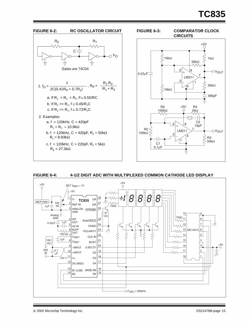
FIGURE 6-2: RC OSCILLATOR CIRCUIT FIGURE 6-3: COMPARATOR CLOCKCIRCUITS
FIGURE 6-4: 4-1/2 DIGIT ADC WITH MULTIPLEXED COMMON CATHODE LED DISPLAY
R2 R1
FO
Gates are 74C04
C
1. fO =1
2C(0.41RP + 0.7R1)
R1 R2
R1 + R2
a. If R1 = R2 = R1, F≅ 0.55/RC
b. If R2 >> R1, f ≅ 0.45/R1C
c. If R2 << R1, f ≅ 0.72/R1C
2. Examples:a. f = 120kHz, C = 420pF
R1 = R2 ≈ 10.9kΩb. f = 120kHz, C = 420pF, R2 = 50kΩ
R1 = 8.93kΩ
c. f = 120kHz, C = 220pF, R2 = 5kΩR1 = 27.3kΩ
, RP =
+5V
VOUT
390pF
30kΩ
7
82
3
16kΩ
0.22µF
16kΩ
4
1kΩ
1
+5V
VOUT
2
3
14
7
6
R2100kΩ
R2100kΩ
R350kΩ
C210pF
R42kΩ
C10.1µF
-
+
LM311
-
+
LM311
56kΩ
28
27
26
25
24
23
22
21
9
8
7
6
5
4
3
2
1
REF IN
ANALOGGND
INTOUT
AZ INBUFFOUT
CREF+
+5V
–5V
UR
DGND
POLARITY
OR
STROBE
RUN/HOLD
CLK IN
BUSY
1
2
3
4
5
6
7
8
9
SET VREF = 1V
100kΩ
AnalogGND
0.33µF
100 kΩ
1µF
1µF
47kΩ
150Ω
+5V
150Ω10
11
12
13
14
15
16
17
18
+5V
MC14513
1µF
20
19
18
17
1615
–INPUT
+INPUT
V+
D5 (MSD)
B1 (LSB)B2
(LSD) D1
D2
D3
D4
B4(MSB) B8
10
11
12
1314
100kΩ
SIGIN
+
–0.1µF
+5V
FOSC = 200kHz
CREF-
V - TC835MCP1525

TC835
DS21478B-page 16 2002 Microchip Technology Inc.
FIGURE 6-5: TEST CIRCUIT
1
2
3
4
56
7
89
1011
12
13
14
28
27
26
25
24
23
22
21
20
19
18
17
16
15
100kΩ
ANALOG GND
100 kΩ
SignalInput
0.1µF
SET VREF = 1V
V-
REF IN
ANALOG COMMON
INT OUT
AZ IN BUFF OUT
CREF-
CREF+
–INPUT
+INPUT
D5 (MSD)
B1 (LSB)
B2
V+
UNDERRANGE
OVERRANGE
STROBE
RUN/HOLD
DIGTAL GND
POLARITY
CLOCK IN
BUSY
(LSD) D1
D2
D4
(MSB) B8
B4
D3+5V
1µF 100 kΩ
1µF 0.47µF
VREF IN
ClockInput120kHz
–5V TC835

2002 Microchip Technology Inc. DS21478B-page 17
TC835
7.0 PACKAGING INFORMATION
7.1 Package Marking Information
Package marking data not available at this time.
7.2 Taping Forms
Component Taping Orientation for 64-Pin PQFP Devices
W
User Direction of Feed
PIN 1
Standard Reel Component Orientationfor TR Suffix Device
P
Package Carrier Width (W) Pitch (P) Part Per Full Reel Reel Size
64-Pin PQFP 32 mm 24 mm 250 13 in
Carrier Tape, Number of Components Per Reel and Reel Size
NOTE: Drawing does not represent total number of pins.
Component Taping Orientation for 44-Pin PQFP Devices
W
User Direction of Feed
PIN 1
Standard Reel Component Orientationfor TR Suffix Device
P
Package Carrier Width (W) Pitch (P) Part Per Full Reel Reel Size
44-Pin PQFP 24 mm 16 mm 500 13 in
Carrier Tape, Number of Components Per Reel and Reel Size
NOTE: Drawing does not represent total number of pins.

TC835
DS21478B-page 18 2002 Microchip Technology Inc.
7.3 Package Dimensions
1.465 (37.21)1.435 (36.45)
.022 (0.56)
.015 (0.38).110 (2.79).090 (2.29)
.150 (3.81)
.115 (2.92)
.070 (1.78)
.045 (1.14)
.555 (14.10)
.530 (13.46)
.200 (5.08)
.140 (3.56)
.015 (0.38)
.008 (0.20)
.700 (17.78)
.610 (15.50)
.610 (15.49)
.590 (14.99)
.040 (1.02)
.020 (0.51)
28-Pin PDIP (Wide) PIN 1
3˚MIN.
Dimensions: inches (mm)
.557 (14.15)
.537 (13.65)
.398 (10.10).390 (9.90)
.031 (0.80) TYP.
.018 (0.45)
.012 (0.30) .398 (10.10).390 (9.90)
.010 (0.25) TYP.
.096 (2.45) MAX.
.557 (14.15)
.537 (13.65)
.083 (2.10)
.075 (1.90)
.041 (1.03)
.026 (0.65)
7 ˚MAX.
.009 (0.23)
.005 (0.13)
44-Pin PQFP
PIN 1
Dimensions: inches (mm)

2002 Microchip Technology Inc. DS21478B-page 19
TC835
7.3 Package Dimensions (Continued)
.018 (0.45)
.012 (0.30)
.031 (0.80) TYP.
.555 (14.10)
.547 (13.90)
.555 (14.10)
.547 (13.90)
.687 (17.45)
.667 (16.95)
.687 (17.45)
.667 (16.95)
.010 (0.25) TYP.
.130 (3.30) MAX.
.120 (3.05)
.100 (2.55)
.041 (1.03)
.031 (0.78)
7˚ MAX.
.009 (0.23)
.005 (0.13)PIN 1
64-Pin PQFP
Dimensions: inches (mm)

TC835
DS21478B-page 20 2002 Microchip Technology Inc.
NOTES:
2002 Microchip Technology Inc. DS21478B-page 21
TC835
SALES AND SUPPORT
Data SheetsProducts supported by a preliminary Data Sheet may have an errata sheet describing minor operational differences and recom-mended workarounds. To determine if an errata sheet exists for a particular device, please contact one of the following:
1. Your local Microchip sales office2. The Microchip Corporate Literature Center U.S. FAX: (480) 792-72773. The Microchip Worldwide Site (www.microchip.com)
Please specify which device, revision of silicon and Data Sheet (include Literature #) you are using.
New Customer Notification SystemRegister on our web site (www.microchip.com/cn) to receive the most current information on our products.

TC835
DS21478B-page 22 2002 Microchip Technology Inc.
NOTES:

2002 Microchip Technology Inc. DS21478B-page 23
TC835
Information contained in this publication regarding deviceapplications and the like is intended through suggestion onlyand may be superseded by updates. It is your responsibility toensure that your application meets with your specifications.No representation or warranty is given and no liability isassumed by Microchip Technology Incorporated with respectto the accuracy or use of such information, or infringement ofpatents or other intellectual property rights arising from suchuse or otherwise. Use of Microchip’s products as critical com-ponents in life support systems is not authorized except withexpress written approval by Microchip. No licenses are con-veyed, implicitly or otherwise, under any intellectual propertyrights.
Trademarks
The Microchip name and logo, the Microchip logo, FilterLab,KEELOQ, microID, MPLAB, PIC, PICmicro, PICMASTER,PICSTART, PRO MATE, SEEVAL and The Embedded ControlSolutions Company are registered trademarks of Microchip Tech-nology Incorporated in the U.S.A. and other countries.
dsPIC, ECONOMONITOR, FanSense, FlexROM, fuzzyLAB,In-Circuit Serial Programming, ICSP, ICEPIC, microPort,Migratable Memory, MPASM, MPLIB, MPLINK, MPSIM,MXDEV, PICC, PICDEM, PICDEM.net, rfPIC, Select Modeand Total Endurance are trademarks of Microchip TechnologyIncorporated in the U.S.A.
Serialized Quick Turn Programming (SQTP) is a service markof Microchip Technology Incorporated in the U.S.A.
All other trademarks mentioned herein are property of theirrespective companies.
© 2002, Microchip Technology Incorporated, Printed in theU.S.A., All Rights Reserved.
Printed on recycled paper.
Microchip received QS-9000 quality systemcertification for its worldwide headquarters,design and wafer fabrication facilities inChandler and Tempe, Arizona in July 1999and Mountain View, California in March 2002.The Company’s quality system processes andprocedures are QS-9000 compliant for itsPICmicro® 8-bit MCUs, KEELOQ® code hoppingdevices, Serial EEPROMs, microperipherals,non-volatile memory and analog products. Inaddition, Microchip’s quality system for thedesign and manufacture of developmentsystems is ISO 9001 certified.

DS21478B-page 24 2002 Microchip Technology Inc.
AMERICASCorporate Office2355 West Chandler Blvd.Chandler, AZ 85224-6199Tel: 480-792-7200 Fax: 480-792-7277Technical Support: 480-792-7627Web Address: http://www.microchip.comRocky Mountain2355 West Chandler Blvd.Chandler, AZ 85224-6199Tel: 480-792-7966 Fax: 480-792-7456
Atlanta500 Sugar Mill Road, Suite 200BAtlanta, GA 30350Tel: 770-640-0034 Fax: 770-640-0307Boston2 Lan Drive, Suite 120Westford, MA 01886Tel: 978-692-3848 Fax: 978-692-3821Chicago333 Pierce Road, Suite 180Itasca, IL 60143Tel: 630-285-0071 Fax: 630-285-0075Dallas4570 Westgrove Drive, Suite 160Addison, TX 75001Tel: 972-818-7423 Fax: 972-818-2924DetroitTri-Atria Office Building32255 Northwestern Highway, Suite 190Farmington Hills, MI 48334Tel: 248-538-2250 Fax: 248-538-2260Kokomo2767 S. Albright RoadKokomo, Indiana 46902Tel: 765-864-8360 Fax: 765-864-8387Los Angeles18201 Von Karman, Suite 1090Irvine, CA 92612Tel: 949-263-1888 Fax: 949-263-1338New York150 Motor Parkway, Suite 202Hauppauge, NY 11788Tel: 631-273-5305 Fax: 631-273-5335San JoseMicrochip Technology Inc.2107 North First Street, Suite 590San Jose, CA 95131Tel: 408-436-7950 Fax: 408-436-7955Toronto6285 Northam Drive, Suite 108Mississauga, Ontario L4V 1X5, CanadaTel: 905-673-0699 Fax: 905-673-6509
ASIA/PACIFICAustraliaMicrochip Technology Australia Pty LtdSuite 22, 41 Rawson StreetEpping 2121, NSWAustraliaTel: 61-2-9868-6733 Fax: 61-2-9868-6755China - BeijingMicrochip Technology Consulting (Shanghai)Co., Ltd., Beijing Liaison OfficeUnit 915Bei Hai Wan Tai Bldg.No. 6 Chaoyangmen BeidajieBeijing, 100027, No. ChinaTel: 86-10-85282100 Fax: 86-10-85282104China - ChengduMicrochip Technology Consulting (Shanghai)Co., Ltd., Chengdu Liaison OfficeRm. 2401, 24th Floor,Ming Xing Financial TowerNo. 88 TIDU StreetChengdu 610016, ChinaTel: 86-28-86766200 Fax: 86-28-86766599China - FuzhouMicrochip Technology Consulting (Shanghai)Co., Ltd., Fuzhou Liaison OfficeUnit 28F, World Trade PlazaNo. 71 Wusi RoadFuzhou 350001, ChinaTel: 86-591-7503506 Fax: 86-591-7503521China - ShanghaiMicrochip Technology Consulting (Shanghai)Co., Ltd.Room 701, Bldg. BFar East International PlazaNo. 317 Xian Xia RoadShanghai, 200051Tel: 86-21-6275-5700 Fax: 86-21-6275-5060China - ShenzhenMicrochip Technology Consulting (Shanghai)Co., Ltd., Shenzhen Liaison OfficeRm. 1315, 13/F, Shenzhen Kerry Centre,Renminnan LuShenzhen 518001, ChinaTel: 86-755-2350361 Fax: 86-755-2366086China - Hong Kong SARMicrochip Technology Hongkong Ltd.Unit 901-6, Tower 2, Metroplaza223 Hing Fong RoadKwai Fong, N.T., Hong KongTel: 852-2401-1200 Fax: 852-2401-3431IndiaMicrochip Technology Inc.India Liaison OfficeDivyasree Chambers1 Floor, Wing A (A3/A4)No. 11, O’Shaugnessey RoadBangalore, 560 025, IndiaTel: 91-80-2290061 Fax: 91-80-2290062
JapanMicrochip Technology Japan K.K.Benex S-1 6F3-18-20, ShinyokohamaKohoku-Ku, Yokohama-shiKanagawa, 222-0033, JapanTel: 81-45-471- 6166 Fax: 81-45-471-6122
KoreaMicrochip Technology Korea168-1, Youngbo Bldg. 3 FloorSamsung-Dong, Kangnam-KuSeoul, Korea 135-882Tel: 82-2-554-7200 Fax: 82-2-558-5934SingaporeMicrochip Technology Singapore Pte Ltd.200 Middle Road#07-02 Prime CentreSingapore, 188980Tel: 65-6334-8870 Fax: 65-6334-8850TaiwanMicrochip Technology Taiwan11F-3, No. 207Tung Hua North RoadTaipei, 105, TaiwanTel: 886-2-2717-7175 Fax: 886-2-2545-0139
EUROPEDenmarkMicrochip Technology Nordic ApSRegus Business CentreLautrup hoj 1-3Ballerup DK-2750 DenmarkTel: 45 4420 9895 Fax: 45 4420 9910FranceMicrochip Technology SARLParc d’Activite du Moulin de Massy43 Rue du Saule TrapuBatiment A - ler Etage91300 Massy, FranceTel: 33-1-69-53-63-20 Fax: 33-1-69-30-90-79GermanyMicrochip Technology GmbHGustav-Heinemann Ring 125D-81739 Munich, GermanyTel: 49-89-627-144 0 Fax: 49-89-627-144-44ItalyMicrochip Technology SRLCentro Direzionale ColleoniPalazzo Taurus 1 V. Le Colleoni 120041 Agrate BrianzaMilan, ItalyTel: 39-039-65791-1 Fax: 39-039-6899883United KingdomMicrochip Ltd.505 Eskdale RoadWinnersh TriangleWokinghamBerkshire, England RG41 5TUTel: 44 118 921 5869 Fax: 44-118 921-5820
04/20/02
*DS21478B*
WORLDWIDE SALES AND SERVICE