permold series maintenance manual · federal aviation regulations far 43.13 and far 145.57 specify...
TRANSCRIPT
Permold SeriesMaintenance
Manual
MODELS I0-550-ABCGNPR
FORM NO. X30634A FAA APPROVED
© 2001 APRIL 2001
Courtesy of Bomar Flying Service www.bomar.biz

ii
CURRENT STATUS OF PAGES AS OF:APRIL 2001
See “Manual Revisions,” in the introduction section for distribution procedure.
THE ORIGINAL DATE OF THIS PUBLICATION IS FEBRUARY 1996. INSERT LATEST PAGES;DESTROY SUPERSEDED PAGES.
WARNINGIf the user of this manual is uncertain whether all current revisions have beenincorporated into the manual, contact Teledyne Continental Motors. Do notperform any operation, maintenance, installation or other operation until themanual is confirmed current.MODEL: I0-550-A,B,C,G, N, P & R FORM X30634A
Cover APRIL 2001ii ORIGINALiii APRIL 2001iv APRIL 1998v APRIL 2001vi APRIL 2001vii APRIL 1998viii ORIGINAL1-1 APRIL 20011-2 ORIGINAL1-3 APRIL 20011-4 APRIL 20011-5 APRIL 20011-6 ORIGINAL1-7 APRIL 20011-8 APRIL 19981-9 APRIL 20011-10 APRIL 19981-11 APRIL 19981-12 APRIL 20011-13 APRIL 20011-14 APRIL 20011-15 APRIL 19981-16 APRIL 19981-17 APRIL 20011-18 APRIL 20011-19 APRIL 20011-20 APRIL 20011-21 APRIL 19981-22 APRIL 20012-1 ORIGINAL2-2 APRIL 19982-3 APRIL 2001
2-4 through4-1 APRIL 19984-2 ORIGINAL5-1 APRIL 20015-2 through5-4 APRIL 19985-5 APRIL 20015-6 through6-1 APRIL 19986-2 ORIGINAL7-1 through7-7 APRIL 20017-8 APRIL 20017-9 APRIL 20017-10 ORIGINAL8-1 APRIL 20018-2 ORIGINAL9-1 APRIL 20019-2 APRIL 19989-3 ORIGINAL9-4 ORIGINAL9-5 APRIL 19989-6 APRIL 20019-7 APRIL 20019-8 ORIGINAL10-1 APRIL 200110-2 ORIGINAL11-1 APRIL 200111-2 ORIGINAL12-1 APRIL 200112-2 ORIGINAL12-3 APRIL 200112-4 APRIL 2001
12-5 APRIL 200112-6 APRIL 199812-7 through12-10 APRIL 200112-11 APRIL 199812-12 ORIGINAL13-1 APRIL 200113-2 APRIL 199813-3 through13-15 APRIL 200113-16 APRIL 199813-17 through13-19 APRIL 200113-20 APRIL 199813-21 APRIL 200113-22 APRIL 200113-23 APRIL 199813-24 APRIL 200113-25 APRIL 200113-26 APRIL 200114-1 APRIL 200114-2 APRIL 200114-3 APRIL 200114-4 APRIL 200114-5 APRIL 199814-6 ORIGINAL15-1 APRIL 199815-2 ORIGINAL15-3 APRIL 199815-4 APRIL 199815-5 ORIGINAL15-6 ORIGINAL16-1 ORIGINAL
16-2 APRIL 200116-3 APRIL 199816-4 APRIL 199817-1 through17-3 APRIL 199817-4 APRIL 200117-5 APRIL 199817-6 APRIL 200117-7 APRIL 199817-8 APRIL 199817-9 APRIL 200117-10 ORIGINAL18-1 APRIL 200118-2 through18-5 APRIL 199818-6 ORIGINAL18-7 ORIGINAL18-8 APRIL 200118-9 APRIL 200118-10 through18-12 APRIL 199818-13 APRIL 200118-14 APRIL 200119-1 through19-3 APRIL 200119-4 APRIL 199819-5 APRIL 199819-6 APRIL 200119-7 APRIL 199819-8 APRIL 200119-9 ORIGINAL19-10 through19-12 APRIL 2001
APRIL 2001
iii
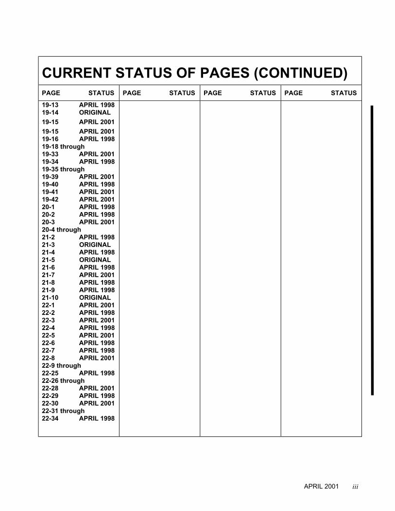
CURRENT STATUS OF PAGES (CONTINUED)PAGE STATUS PAGE STATUS PAGE STATUS PAGE STATUS
19-13 APRIL 199819-14 ORIGINAL19-15 APRIL 200119-15 APRIL 200119-16 APRIL 199819-18 through19-33 APRIL 200119-34 APRIL 199819-35 through19-39 APRIL 200119-40 APRIL 199819-41 APRIL 200119-42 APRIL 200120-1 APRIL 199820-2 APRIL 199820-3 APRIL 200120-4 through21-2 APRIL 199821-3 ORIGINAL21-4 APRIL 199821-5 ORIGINAL21-6 APRIL 199821-7 APRIL 200121-8 APRIL 199821-9 APRIL 199821-10 ORIGINAL22-1 APRIL 200122-2 APRIL 199822-3 APRIL 200122-4 APRIL 199822-5 APRIL 200122-6 APRIL 199822-7 APRIL 199822-8 APRIL 200122-9 through22-25 APRIL 199822-26 through22-28 APRIL 200122-29 APRIL 199822-30 APRIL 200122-31 through22-34 APRIL 1998
APRIL 2001
iv
WARNINGUse only parts meeting the engine type design.
Replacement PartsBeware of replacement parts, materials and accessories that may be sold as aircraft quality butwhose origin and quality are not known. These parts may be deceptively advertised as "unused,""like new," or "remanufactured," and purchasers are often unaware that they are not eligible for useon certificated aircraft. The hazards involved in installing these types of parts on your aircraft areobvious.
Know Your SupplierMany original parts and components are copied and the copies are sold at discounted prices forinstallation on U.S. certified aircraft. An original manufacturer's part is often used as a guide to makeduplicates that appear to be as good as the original, but there are many unknowns about the qualityof design, materials, and workmanship. Other factors that go into quality parts are the degree of heattreating and plating, and inspections, tests, and calibrations. Unfortunately, a cheaply produced partthat looked "as good as the original" is usually found out too late.Federal Aviation Regulations FAR 43.13 and FAR 145.57 specify performance rules for replacementof parts and materials used in the maintenance and alteration of United States certificated aircraft.FAR 91.403, FAR 121.363, FAR 123.45, and FAR 135.143 (a) holds the owner/operator responsiblefor the continued airworthiness of the aircraft, and that includes the quality of replacement parts.
Identifying Approved PartsApproved serviceable replacement parts are identified by:1. Federal Aviation Administration (FAA) Form 8130-3 Airworthiness Approval Tag. An
Airworthiness Approval Tag identifies a part or group of parts that have been approved by anauthorized FAA representative.
2. FAA Technical Standard Order (TSO) number and identification mark indicating that the part orappliance was manufactured in accordance with the requirements of FAR 21 Subpart O.
3. FAA Parts Manufacturer Approval (PMA) symbol with the manufacturer's name, part number,make and model of the type certified product on which the part can legally be installed stampedon the part. An FAA/PMA is issued under FAR 21.305. Make and model information may be on atag attached to the part.
4. Shipping ticket, invoice, or other document which verifies that the part was manufactured by afacility that was holding an FAA Approved Production Inspection System Certificate issued underFAR 21 Subpart F, or by a manufacturer holding an FAA Production Certificate issued underFAR 21 Subpart G.
5. Certificate of airworthiness for export issued by governments in countries other than the UnitedStates of America under the provisions of FAR 21 Subpart N.
It's Your ResponsibilityThe owner/operator is responsible for the continued airworthiness of the aircraft. In accordance withFAR, certification of materials, parts and appliances for return to service for use on aircraft is theresponsibility of the person/agency who signs the approval. To insure the continued safe operationof your aircraft, you must exercise great care when inspecting, testing, and determining theacceptability of all parts and materials. A very important part of this is verifying the origin of allmaterials, parts, and accessories that are used on your aircraft .
APRIL 1998
v
Notice to all usersThis manual does not contain maintenance information for supplemental type certificatedcomponents or systems. This manual contains information on engines, components and systemsdesigned, tested and certified by TCM in accordance with the pertinent type design data.
This manual contains maintenance information only. All personnel involved with these functionsmust thoroughly read and understand the information provided; these instructions provide theprocedures necessary to operate, maintain and install an engine and they must be followedcarefully.
This manual contains no warranties, either expressed or implied.
Publication Format
This publication is formatted for practical use and ease of reference. Due to the large volume ofinformation necessary for maintenance, chapters are independently numbered. For example,chapter 1 begins on page 1; chapter 2 begins again with page 1, etc. To locate information easily,use the Publication Table of Contents and the Chapter Contents provided at each division.
WARNINGThe Operator and Installation manual, Maintenance, manual, Overhaul manual,Service Documents and the Parts Catalog constitute the instructions for ContinuedAirworthiness prepared by TCM as approved by the FAA, pursuant to FAR Part 33. Asrequired by FAR § 43.13, each person performing overhaul, maintenance, alterationor preventive maintenance on the engine or accessories must use the methods,techniques and practices prescribed in the Instructions for Continued Airworthiness.Failure to comply with the Instructions for Continued Airworthiness may result inengine malfunction, engine failure, injury or death.
To The MechanicPrior to performing, maintenance, alteration, overhaul or preventive maintenance the mechanicmust meet requirements of FAR 65 and must follow FAR Parts 43, 91 and 145 as applicable. Usethis manual in conjunction with Teledyne Continental Motors (TCM) service documents, relatedpublications, accessory manufacturer’s instructions, FAR and FAA Advisory Circulars.
APRIL 2001

vi
Notes, Cautions and Warnings…
NOTE...Special interest information which may facilitate performance of a procedure or operation ofequipment.
CAUTION...Used to emphasize certain information or instructions which if disregarded may result in damage toengine or accessories.
WARNINGUsed to provide warning and/or instructions which if disregarded, will endangerpersonnel and/or severely damage the engine resulting in subsequent enginemalfunction or failure.
Notes, cautions and warnings do not impose undue restrictions. They are inserted to obtainmaximum safety, efficiency and performance. Abuse, misuse or neglect of equipment can causeeventual engine malfunction or failure.
APRIL 2001

vii
CHAPTER INDEXCOVER PAGES PAGE
Status Page...................................................................................................................... iiiWARNING ........................................................................................................................ivNotice To All Users...........................................................................................................vNotes, Cautions and Warnings.........................................................................................vi
CHAPTER ............................................................................................................................ PAGE1 Introduction............................................................................................................... 1-32 Tools (Maintenance)................................................................................................. 2-13 Approved Products .................................................................................................. 3-14 Airworthiness Limitations.......................................................................................... 4-15 Time Limits/Operational Inspection/Troubleshooting .............................................. 5-16 Unpacking/De-inhibiting/lnstallation & Test ............................................................. 6-17 Servicing, Fluids ...................................................................................................... 7-18 Engine Preservation and Storage ............................................................................ 8-19 Standard Practices .................................................................................................. 9-110 Engine Maintenance ................................................................................................ 10-111 Exhaust System ....................................................................................................... 11-112 Ignition System ........................................................................................................ 12-113 Fuel System ............................................................................................................. 13-114 Induction System ..................................................................................................... 14-115 Air Conditioning System .......................................................................................... 15-116 Electrical Charging System ...................................................................................... 16-117 Starter & Starter Adapter .......................................................................................... 17-118 Lubrication System................................................................................................... 18-119 Cylinder Assembly ................................................................................................... 19-120 Crankcase ................................................................................................................ 20-121 Engine Drive Train.................................................................................................... 21-122 Post Maintenance Adjustment And Test ................................................................. 22-1
APRIL 1998

viii
INTENTIONALLY
LEFT
BLANK
1-1
CHAPTER 1
SECTION PAGE1-1 Introduction ................................................................................................... 1-31-2 Scope............................................................................................................ 1-31-3 Definition of Terms........................................................................................ 1-31-4 Manual Revisions ......................................................................................... 1-31-5 Related Publications ..................................................................................... 1-41-6 Service Documents....................................................................................... 1-51-7 Service Reports and Inquiries....................................................................... 1-51-8 Description of Engine Model Code ............................................................... 1-71-9 Engine Design Features ............................................................................... 1-71-10 General ......................................................................................................... 1-201-11 Engine Specifications ................................................................................... 1-201-12 Operating Limits............................................................................................ 1-20
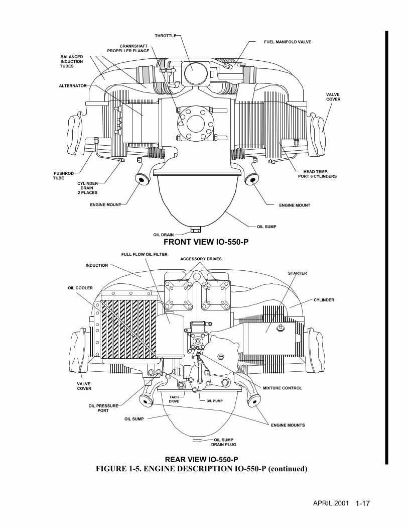
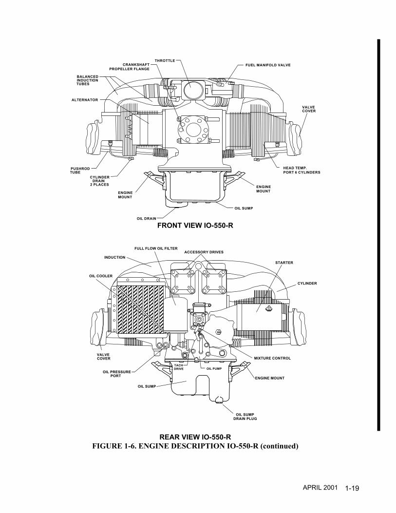
FIGURE PAGE1-1 Engine Description I0-550-A......................................................................... 1-81-2 Engine Description I0-550-B......................................................................... 1-101-3 Engine Description I0-550-C......................................................................... 1-121-4 Engine Description I0-550-G & N ................................................................. 1-141-5 Engine Description I0-550-P......................................................................... 1-161-6 Engine Description I0-550-R......................................................................... 1-18
APRIL 2001

1-2
INTENTIONALLY
LEFT
BLANK
1-3
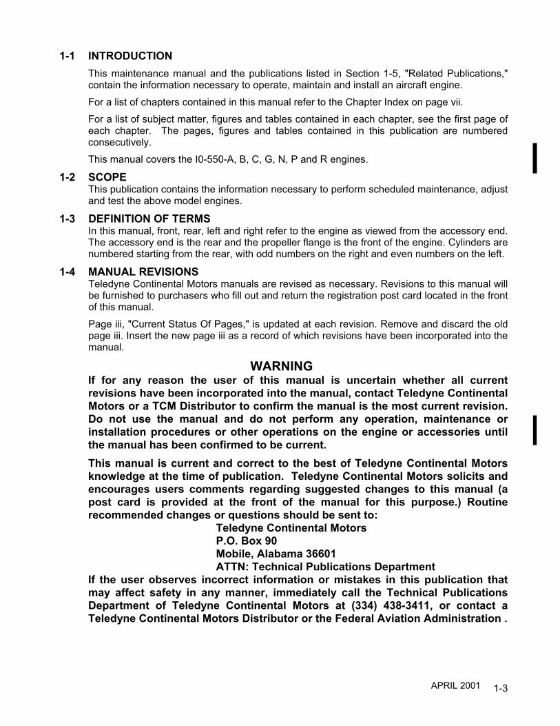
1-1 INTRODUCTIONThis maintenance manual and the publications listed in Section 1-5, "Related Publications,"contain the information necessary to operate, maintain and install an aircraft engine.For a list of chapters contained in this manual refer to the Chapter Index on page vii.For a list of subject matter, figures and tables contained in each chapter, see the first page ofeach chapter. The pages, figures and tables contained in this publication are numberedconsecutively.This manual covers the I0-550-A, B, C, G, N, P and R engines.
1-2 SCOPEThis publication contains the information necessary to perform scheduled maintenance, adjustand test the above model engines.
1-3 DEFINITION OF TERMSIn this manual, front, rear, left and right refer to the engine as viewed from the accessory end.The accessory end is the rear and the propeller flange is the front of the engine. Cylinders arenumbered starting from the rear, with odd numbers on the right and even numbers on the left.
1-4 MANUAL REVISIONSTeledyne Continental Motors manuals are revised as necessary. Revisions to this manual willbe furnished to purchasers who fill out and return the registration post card located in the frontof this manual.Page iii, "Current Status Of Pages," is updated at each revision. Remove and discard the oldpage iii. Insert the new page iii as a record of which revisions have been incorporated into themanual.
WARNINGIf for any reason the user of this manual is uncertain whether all currentrevisions have been incorporated into the manual, contact Teledyne ContinentalMotors or a TCM Distributor to confirm the manual is the most current revision.Do not use the manual and do not perform any operation, maintenance orinstallation procedures or other operations on the engine or accessories untilthe manual has been confirmed to be current.This manual is current and correct to the best of Teledyne Continental Motorsknowledge at the time of publication. Teledyne Continental Motors solicits andencourages users comments regarding suggested changes to this manual (apost card is provided at the front of the manual for this purpose.) Routinerecommended changes or questions should be sent to:
Teledyne Continental MotorsP.O. Box 90Mobile, Alabama 36601ATTN: Technical Publications Department
If the user observes incorrect information or mistakes in this publication thatmay affect safety in any manner, immediately call the Technical PublicationsDepartment of Teledyne Continental Motors at (334) 438-3411, or contact aTeledyne Continental Motors Distributor or the Federal Aviation Administration .
APRIL 2001
1-4
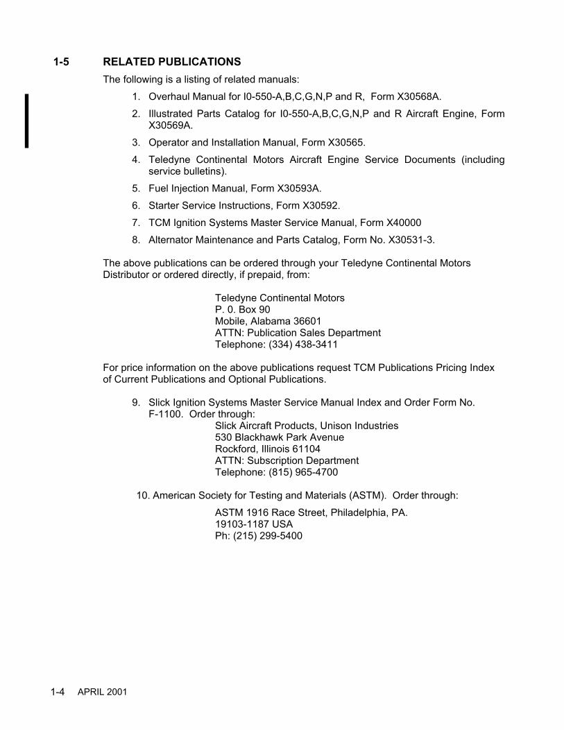
1-5 RELATED PUBLICATIONSThe following is a listing of related manuals:
1. Overhaul Manual for I0-550-A,B,C,G,N,P and R, Form X30568A.2. Illustrated Parts Catalog for I0-550-A,B,C,G,N,P and R Aircraft Engine, Form
X30569A.3. Operator and Installation Manual, Form X30565.4. Teledyne Continental Motors Aircraft Engine Service Documents (including
service bulletins).5. Fuel Injection Manual, Form X30593A.6. Starter Service Instructions, Form X30592.7. TCM Ignition Systems Master Service Manual, Form X400008. Alternator Maintenance and Parts Catalog, Form No. X30531-3.
The above publications can be ordered through your Teledyne Continental MotorsDistributor or ordered directly, if prepaid, from:
Teledyne Continental MotorsP. 0. Box 90Mobile, Alabama 36601ATTN: Publication Sales DepartmentTelephone: (334) 438-3411
For price information on the above publications request TCM Publications Pricing Indexof Current Publications and Optional Publications.
9. Slick Ignition Systems Master Service Manual Index and Order Form No.F-1100. Order through:
Slick Aircraft Products, Unison Industries530 Blackhawk Park AvenueRockford, Illinois 61104ATTN: Subscription DepartmentTelephone: (815) 965-4700
10. American Society for Testing and Materials (ASTM). Order through:ASTM 1916 Race Street, Philadelphia, PA.19103-1187 USAPh: (215) 299-5400
APRIL 2001

1-5
1-6 SERVICE DOCUMENTSTeledyne Continental Motors service documents are divided into six categories: (1) MandatoryService Bulletin, (2) Critical Service Bulletin, (3) Service Bulletin, (4) Service InformationDirective (5) Service Information Letter and (6) Special Service Notice (SSN). See Section 1-5,"Related Publications," for service document ordering information.
SERVICE DOCUMENT CATEGORY DEFINITIONSCATEGORY 1: "MANDATORY SERVICE BULLETIN" (MSB)- Service documents relating toknown or suspected hazards to safety that have been incorporated in whole or in part in anAirworthiness Directive (AD) issued by the FAA or have been issued, at the direction of FAA, bythe manufacturer in order to require compliance with an already issued AD (or an equivalentissued by another country's airworthiness authority).
CATEGORY 2: "CRITICAL SERVICE BULLETIN" (CSB)- Service documents (not included inCategory 1) that have been determined by the product manufacturer to constitute a threat tocontinued safe operation of an aircraft or to persons or property on the ground unless somespecific action (inspection, repair, replacement, etc..) is taken by the product owner or operator.Documents in this category may be incorporated in an Airworthiness Directive issued by theFAA.
CATEGORY 3: "SERVICE BULLETIN" (SB)- Service documents (not included in Categories 1and 2) considered by the product manufacturer to constitute a substantial improvement to theinherent safety of an aircraft or component of an aircraft. This "Service Bulletin" category alsoincludes updates of instructions for continued airworthiness.
CATEGORY 4: "SERVICE INFORMATION DIRECTIVE" (SID)- Service documents (notincluded in Categories 1, 2 or 3) that have been determined by the manufacturer to be of valueto an owner/operator in the use of a product by enhancing safety, maintenance or economy.
CATEGORY 5: "SERVICE INFORMATION LETTER" (SIL)- This category includes allinformation (not included in Categories 1 through 4) that may be of use to the owner/operator ormaintainer of the aircraft.
CATEGORY 6 “SPECIAL SERVICENOTICE” (SSN)-TCM may issue a Special Service Notice when a product condition can berectified by direct contact with each customer to whom the product was delivered. Specialservice notices will be upgraded to Service Bulletins if confirmation of compliance with theSpecial Service Notice cannot be verified by TCM.
1-7 SERVICE REPORTS AND INQUIRIESIf for any reason you have an inquiry or require technical assistance, contact your local TCMdistributor or TCM field representative. Requests for copies of Teledyne Continental AircraftEngine service publications should be made through your distributor or Teledyne ContinentalMotors, P. 0. Box 90, Mobile, AL 36601, ATTN: Publications Sales Department.
1-8 TCM INTERNET SITEAccess the TCM internet site at WWW.TCMLINK.COM
APRIL 2001

1-6
INTENTIONALLY
LEFT
BLANK
1-7
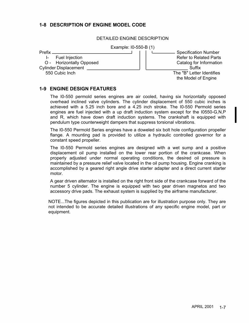
1-8 DESCRIPTION OF ENGINE MODEL CODE
DETAILED ENGINE DESCRIPTION
Example: I0-550-B (1)Prefix Specification Number
I- Fuel Injection Refer to Related PartsO - Horizontally Opposed Catalog for Information
Cylinder Displacement Suffix 550 Cubic Inch The "B" Letter Identifies
the Model of Engine
1-9 ENGINE DESIGN FEATURESThe I0-550 permold series engines are air cooled, having six horizontally opposedoverhead inclined valve cylinders. The cylinder displacement of 550 cubic inches isachieved with a 5.25 inch bore and a 4.25 inch stroke. The I0-550 Permold seriesengines are fuel injected with a up draft induction system except for the I0550-G,N,Pand R, which have down draft induction systems. The crankshaft is equipped withpendulum type counterweight dampers that suppress torsional vibrations.The I0-550 Permold Series engines have a doweled six bolt hole configuration propellerflange. A mounting pad is provided to utilize a hydraulic controlled governor for aconstant speed propeller.The I0-550 Permold series engines are designed with a wet sump and a positivedisplacement oil pump installed on the lower rear portion of the crankcase. Whenproperly adjusted under normal operating conditions, the desired oil pressure ismaintained by a pressure relief valve located in the oil pump housing. Engine cranking isaccomplished by a geared right angle drive starter adapter and a direct current startermotor.A gear driven alternator is installed on the right front side of the crankcase forward of thenumber 5 cylinder. The engine is equipped with two gear driven magnetos and twoaccessory drive pads. The exhaust system is supplied by the airframe manufacturer.
NOTE...The figures depicted in this publication are for illustration purpose only. They arenot intended to be accurate detailed illustrations of any specific engine model, part orequipment.
APRIL 2001

1-8
#5 #3 #1
#6 #4 #2
ALTERNATOR
INDUCTIONBALANCE TUBE
FUELMANIFOLDVALVE
OIL FILLER & CRANKCASEBREATHER
1200 SERIES MAGNETO
OIL COOLER
INDUCTION TUBE
OIL FILTER
FUEL PUMP
STARTER ADAPTER
ENGINE MOUNT
STARTER MOTOR
TOP VIEW IO-550-A
Continental Continental Continental
SPARK PLUG
FUEL MANIFOLD VALVE
OIL FILLER & DIPSTICK
MAGNETOS
OIL COOLER
OIL FILTER
FUEL PUMP
FUELMETERING
UNIT
OIL PRESSURECONNECTION
INDUCTION TUBEOIL SUMPDRAIN
OIL SUMPENGINEMOUNT
INDUCTIONBALANCE
TUBE
PROPGOVERNOR
PAD
OIL TEMPERATURECONNECTION
SIDE VIEW IO-550-A
FIGURE 1-1. ENGINE DESCRIPTION I0-550-A
APRIL 1998

1-9
STARTERMOTOR
FUEL RETURNFROM METERING UNIT
VAPOR RETURN TOTANK
VACUUM PUMPRETURNAND 20000
DRIVE PADFUEL INLET
FROM FUEL TANK
ENGINE MOUNT4 PLACES
ELECTRICAL TACHDRIVE AND 20005
MAGNETO SWITCHCONNECTION
RETARDCONNECTION
OIL SUMP DRAININTAKE MANIFOLDDRAIN
INTAKE MANIFOLDDRAIN
MANIFOLD PRESSURE REFERENCE
FUEL PUMP OUTLETTO FUEL CONTROL
ALTERNATOR
INDUCTION MANIFOLDBALANCE TUBE
PUSHRODHOUSING
ROCKERCOVER
CYLINDER HEAD
CYLINDER BARREL
OIL TEMPERATURECONTROL VALVE(VERNATHERM)
FUEL PUMP
OIL COOLER
STARTER ADAPTEROIL FILTER
HEAD TEMP.PORT 6 CYLINDERS
THROTTLE ASSEMBLY
FIGURE 1-1. ENGINE DESCRIPTION IO-550-A (continued)
APRIL 2001
FRONT VIEW IO-550-A
REAR VIEW IO-550-A

1-10
#5 #3 #1
#6 #4 #2
ALTERNATOR
INDUCTIONBALANCE TUBE
FUELMANIFOLDVALVE
OIL FILLER &CRANKCASEBREATHER
MAGNETO
OIL COOLER
INDUCTION TUBE
OIL FILTER
FUEL PUMP
STARTER ADAPTER
ENGINE MOUNT
STARTER MOTOR
TOP VIEW IO-550-B
Continental Continental Continental
SPARK PLUG
FUEL MANIFOLD VALVE
OIL FILLER & DIPSTICK
MAGNETOS
OIL COOLER
OIL FILTER
FUEL METERING UNIT
INDUCTION TUBE
OIL SUMP
ENGINEMOUNT
INDUCTIONBALANCE
TUBE
PROPGOVERNOR
PAD
OIL TEMPERATURECONNECTION
OIL PRESSURECONNECTION
SIDE VIEW IO-550-B
FIGURE 1-2. ENGINE DESCRIPTION I0-550-B
APRIL 1998

1-11
MAGNETO SWITCHCONNECTION
RETARDCONNECTION
ENGINEMOUNT
ALTERNATORCYLINDER BARREL
CYLINDER HEAD
ROCKERCOVER PUSHROD
HOUSING
OIL SUMP
MANIFOLDDRAIN
INDUCTIONBALANCE TUBE
HEAD TEMP.PORT 6 CYLINDERS
FRONT VIEW IO-550-B
�������������������������������������������������������������������������������������������
�������������������������������������������������������������������������������������������
������������������������������������������������������������������������������
�������������������������������������������������������������������������������������������
�������������������������������������������������������������������������������������������
�������������������������������������������������������������������������������������������
������������������������������������������������������������������������������
�������������������������������������������������������������������������������������������
�������������������������������������������������������������������������������������������
FUEL OUTLETTO FUEL CONTROL
FUEL INLET FROMFUEL TANK
VACUUM PUMPRETURN
AND 20000DRIVE PAD
VAPOR RETURN TOTANK
FUEL RETURN FROM FUELCONTROL
STARTER MOTOR
TACH DRIVE
SEAL DRAIN
INTAKE MANIFOLD DRAIN
OIL FILTER
FUEL PUMP
STARTER ADAPTER
MANIFOLD PRESSURE REFERENCE
INTAKE MANIFOLD DRAIN
THROTTLE
FUEL CONTROLUNIT
OIL TEMPERATURECONTROL VALVE(VERNATHERM)
OIL PUMP
REAR VIEW IO-550-BFIGURE 1-2. ENGINE DESCRIPTION I0-550-B (continued )
APRIL 1998

1-12
ALTERNATOR
VALVE COVERS
FUEL INJECTORS
CRANKCASE
INDUCTION SYSTEMBALANCE TUBE
OIL COOLER
OIL FILTER
THROTTLE &FUEL CONTROL
CYLINDERASSEMBLY
MAGNETOS
OIL FILLER ANDCRANKCASE BREATHER
FUEL MANIFOLD VALVE
STARTERMOTOR
#6 #4 #2
#5 #3 #1
CRANKSHAFTAND PROPFLANGE
STARTER ADAPTER
TOP VIEW IO-550-C
Continental Continental Continental
SPARK PLUG
FUEL MANIFOLD VALVE
OIL FILLER & DIPSTICK
MAGNETOS
OIL COOLER
OIL FILTER
FUEL PUMP
FUELMETERING
UNIT
INDUCTION TUBE
OIL SUMPDRAIN
OIL SUMP
ENGINEMOUNT
INDUCTIONBALANCE
TUBE
PROPGOVERNOR
PAD
ENGINEMOUNT
OIL PRESSUREPORT
OIL TEMPERATUREPORT
SIDE VIEW IO-550-CFIGURE 1-3. ENGINE DESCRIPTION I0-550-C
APRIL 2001

1-13
OIL FILTER
OIL COOLER
ROCKER COVER
CYLINDER HEAD
PUSHRODHOUSING
ENGINEMOUNT STARTER ADAPTER
INLET FROM FUEL PUMPTHROTTLE
MAGNETO SWITCHCONNECTIONRETARD
CONNECTION
OIL SUMP DRAIN
INTAKEMANIFOLDDRAIN
ALTERNATOR
INDUCTIONMANIFOLDBALANCETUBE
PUSHRODHOUSING
ROCKERCOVER
CYLINDER HEADCYLINDER BARREL
HEAD TEMP.PORT 6 CYLINDERS
REAR VIEW IO-550-C
FIGURE 1-3. ENGINE DESCRIPTION I0-550-C (continued)
FRONT VIEW IO-550-C
APRIL 2001

1-14
CRANKSHAFTAND FLANGE
ALTERNATOR
VALVE COVERS
SPARK PLUGS
FUEL MANIFOLDVALVE
CRANKCASE
INDUCTIONTUBES
OIL COOLER
OIL FILTER
FUEL PUMP
STARTER
CYLINDERASSEMBLY
MAGNETOS
OIL FILLER ANDCRANKCASE BREATHER
STARTERADAPTER
TOP VIEW IO-550-G & N
OIL COOLER
FUEL MANIFOLDVALVE
MAGNETOSINDUCTION SYSTEM
VERNATHERM
OIL FILLER& DIPSTICK
ENGINE MOUNTS
PROP GOVERNORDRIVE PAD
CRANKSHAFTPROPFLANGE OIL FILTER
90o TACH DRIVE
FUEL CONTROL& THROTTLE
SPARKPLUG
OIL TEMP.PORT
SIDE VIEW IO-550-G & N*
*The IO-550-N is externally identical to the IO-550-G except fortapered cylinder barrel fins
FIGURE 1-4. ENGINE DESCRIPTION I0-550-G & N
APRIL 2001

1-15
FUEL MANIFOLD VALVETHROTTLE
ALTERNATOR
BALANCEDINDUCTIONTUBES
CRANKSHAFTPROPELLER FLANGE
ENGINE MOUNT ENGINE MOUNT
OIL SUMP
OIL DRAIN
CYLINDERDRAIN
2 PLACES
PUSHRODTUBE
VALVE COVER
HEAD TEMP.PORT 6 CYLINDERS
SIDE VIEW IO-550-G & N
OIL COOLER
����������������������������������������������������������������������������������������������������������������
��������������������������������������������������������������������������������������������������������������������������������
��������������������������������������������������������������������������������������������������������������������������������
��������������������������������������������������������������������������������������������������������������������������������
��������������������������������������������������������������������������������������������������������������������������������
����������������������������������������������������������������������������������������������������������������
����������������������������������������������������������������������������������������������������������������
����������������������������������������������������������������������������������������������������������������
��������������������������������������������������������������������������������������������������������������������������������
FULL FLOW OIL FILTER
OIL SUMP
OIL SUMPDRAIN PLUG
ACCESSORY DRIVES
ENGINE MOUNTS
STARTER
MIXTURE CONTROL
INDUCTION
VALVECOVER
CYLINDER
OIL PUMPTACHDRIVE
OIL PRESSUREPORT
REAR VIEW IO-550-G & NFIGURE 1-4. ENGINE DESCRIPTION I0-550-G & N (continued)
APRIL 1998
Courtesy of Bomar Flying Service www.bomar.biz

1-16
FUEL MANIFOLDVALVE
MAGNETOS
INDUCTIONSYSTEM
VERNATHERM
OIL FILLER& DIPSTICK
PROP GOVERNORDRIVE PAD
CRANKSHAFTPROP FLANGE
OIL COOLER
OIL FILTER
FUEL CONTROL& THROTTLE
SPARKPLUG
OIL TEMPERATUREPORT
ENGINE MOUNTS
90o TACH DRIVE
SUMPPLUG
SIDE VIEW IO-550-PFigure 1-5. ENGINE DESCRIPTION IO-550-P
CRANKSHAFTAND FLANGE
ALTERNATOR
VALVE COVERS
SPARK PLUGS
FUEL MANIFOLDVALVE
CRANKCASE
INDUCTIONTUBES
OIL COOLER
OIL FILTER
FUEL PUMP
STARTER
CYLINDERASSEMBLY
MAGNETOS
OIL FILLER ANDCRANKCASE BREATHER
STARTERADAPTER
TOP VIEW IO-550-P
APRIL 1998
1-17
FUEL MANIFOLD VALVETHROTTLE
ALTERNATOR
BALANCEDINDUCTIONTUBES
CRANKSHAFTPROPELLER FLANGE
ENGINE MOUNT ENGINE MOUNT
OIL SUMP
OIL DRAIN
CYLINDERDRAIN
2 PLACES
PUSHRODTUBE
VALVECOVER
HEAD TEMP.PORT 6 CYLINDERS
FRONT VIEW IO-550-P
OIL COOLER
FULL FLOW OIL FILTER
OIL SUMP
OIL SUMPDRAIN PLUG
ACCESSORY DRIVES
ENGINE MOUNTS
STARTER
MIXTURE CONTROL
INDUCTION
VALVECOVER
CYLINDER
OIL PUMPTACHDRIVE
OIL PRESSUREPORT
REAR VIEW IO-550-PFIGURE 1-5. ENGINE DESCRIPTION IO-550-P (continued)
APRIL 2001

1-18
CRANKSHAFTAND FLANGE
ALTERNATOR
VALVE COVERS
SPARK PLUGS
FUEL MANIFOLDVALVE
CRANKCASE
INDUCTIONTUBES
OIL COOLER
OIL FILTER
FUEL PUMP
STARTER
CYLINDERASSEMBLY
MAGNETOS
OIL FILLER ANDCRANKCASE BREATHER
TOP VIEW IO-550-R
OIL COOLER
FUEL MANIFOLDVALVE
MAGNETOSINDUCTION SYSTEM
VERNATHERM
OIL FILLER& DIPSTICK
PROP GOVERNORDRIVE PAD
CRANKSHAFTPROPFLANGE OIL FILTER
90 o TACH DRIVE
FUEL CONTROL& THROTTLE
SPARKPLUG
OIL TEMP.PORT
ENGINEMOUNTS
SIDE VIEW IO-550-RFIGURE 1-6. ENGINE DESCRIPTION IO-550-R
APRIL 2001
STARTERADAPTER
1-19
FUEL MANIFOLD VALVETHROTTLE
ALTERNATOR
BALANCEDINDUCTIONTUBES
CRANKSHAFTPROPELLER FLANGE
CYLINDERDRAIN
2 PLACES
PUSHRODTUBE
VALVE COVER
HEAD TEMP.PORT 6 CYLINDERS
OIL SUMP
OIL DRAIN
ENGINEMOUNT
ENGINEMOUNT
FRONT VIEW IO-550-R
OIL COOLER
FULL FLOW OIL FILTERACCESSORY DRIVES
STARTERINDUCTION
CYLINDER
OIL SUMP
OIL SUMPDRAIN PLUG
ENGINE MOUNT
MIXTURE CONTROLVALVECOVER
OIL PUMPTACHDRIVE
OIL PRESSUREPORT
REAR VIEW IO-550-RFIGURE 1-6. ENGINE DESCRIPTION IO-550-R (continued)
APRIL 2001

1-20
1-10 GENERAL
The operating limits and specifications listed in this section are applicable to the I0-550Permold Series aircraft engines. Consult the I0-550 Operator And Installation Manual, FormX30565 for additional operating procedures.
For time between overhaul (T80) for I0-550 Permold Series engines see section 5-3 and thelatest TBO Service Bulletin (Revised Overhaul Periods For All Teledyne Continental AircraftEngines). Accessories supplied with engine by TCM have the same TBO; with criteria forservice and longevity outlined in current TCM TBO Service Bulletins, unless otherwisespecified.
1-11 ENGINE SPECIFICATIONSManufacturer Teledyne Continental MotorsModels I0-550-A, B, C, G, N, P & RCylinders
Arrangement.................................................................................... horizontally opposedCompression Ratio ................................................................................................... 8.5:1Firing Order .................................................................................................... 1-6-3-2-5-4Number of cylinders........................................................................................................ 6Bore (Inches) ..............................................................................................................5.25Stroke (Inches) ...........................................................................................................4.25Piston Displacement (cu in ) ....................................................................................... 550
Brake HorsepowerRated Maximum Continuous Operation (I0-550-A,B&C)............................................. 300Rated Maximum Continuous Operation (I0-550-G)..................................................... 280Rated Maximum Continuous Operation (I0-550-N, P, R) ............................................ 310
1-12 OPERATING LIMITSNOTE...The following specifications apply to all I0-550 Permold Series engines unless otherwisespecified.
Crankshaft Speed - RPMRated Maximum Continuous Operation (I0550-A,B,C,N,P,R) ....................................2700Rated Maximum Continuous Operation (I0550-G) .....................................................2500Idle........................................................................................................................600 Min.
Intake Manifold Pressure At Idle (In. Hg.) ................................................................ 18.5 Max.Fuel Control System..................................................... Continental Continuous Flow InjectorFuel ........................................................................ For Fuel grade, see Chapter 7, ServicingOil ............................................................For Oil grade & capacity, see Chapter 7, Servicing
Oil PressureIdle, Minimum, psi @75° F ............................................................................................10Normal Operation, psi @ 200° F .........................................................................30 to 60
Oil Sump Capacity (U.S. Quarts) I0-550-A,B,C,R ...............................................................12Oil Sump Capacity (U.S. Quarts) I0-550- G & N .................................................................. 8Oil Sump Capacity (U.S. Quarts) I0-550- P.........................................................................10Oil Consumption (Lb /BHP/Hr. Max.)..............................................................006 X % Power
100
APRIL 2001

1-21
Oil Temperature LimitsMinimum for Take-Off ..............................................................................................75°FLimit ....................................................................................................................... 240°FRecommended Operational.......................................................................... 170°-220°F
Ignition Timing (Compression stroke, breaker opens)Right Magneto, degrees BTC ...............................................................................22° ± 1°Left Magneto, degrees BTC..................................................................................22° ± 1°
The following spark plugs are approved for use in engine models according to the followinglisting:I0-550 Permold Series:
Use: TCM 634675Champion RHB32E
Spark Plug Gap ...............................................Use spark plug manufacturer's specified gap
APRIL 1998
1-22
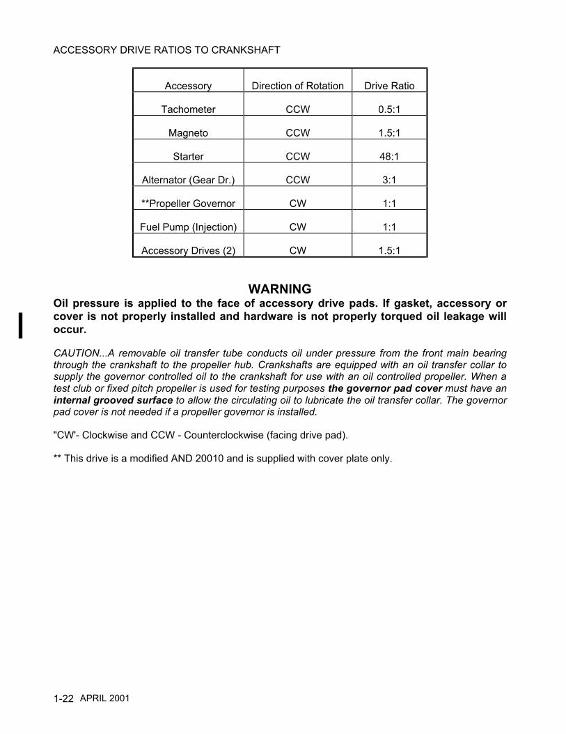
ACCESSORY DRIVE RATIOS TO CRANKSHAFT
Accessory Direction of Rotation Drive Ratio
Tachometer CCW 0.5:1
Magneto CCW 1.5:1
Starter CCW 48:1
Alternator (Gear Dr.) CCW 3:1
**Propeller Governor CW 1:1
Fuel Pump (Injection) CW 1:1
Accessory Drives (2) CW 1.5:1
WARNINGOil pressure is applied to the face of accessory drive pads. If gasket, accessory orcover is not properly installed and hardware is not properly torqued oil leakage willoccur.
CAUTION...A removable oil transfer tube conducts oil under pressure from the front main bearingthrough the crankshaft to the propeller hub. Crankshafts are equipped with an oil transfer collar tosupply the governor controlled oil to the crankshaft for use with an oil controlled propeller. When atest club or fixed pitch propeller is used for testing purposes the governor pad cover must have aninternal grooved surface to allow the circulating oil to lubricate the oil transfer collar. The governorpad cover is not needed if a propeller governor is installed.
"CW'- Clockwise and CCW - Counterclockwise (facing drive pad).
** This drive is a modified AND 20010 and is supplied with cover plate only.
APRIL 2001
2-1
CHAPTER 2
TOOLS AND EQUIPMENT
Section Page
2-1 General Information........................................................................... 2-22-2 Possible Special Tool Procurement Sources .................................... 2-32-3 Special Tools..................................................................................... 2-4

2-2
2-1 GENERAL INFORMATIONThe mechanic should be equipped with a complete set of the necessary tools that include thefollowing:
1. Wrenches - 1/4” through 1 1/4"
2. Common and Philips Head Screwdrivers
3. Pliers - Common, Diagonal Cutters, Needle Nose, Duck Bill, Snap Ring , Safety Wire
4. Ratchets 1/4", 3/8", 1/2" Drive
5. Sockets - 1/4”' Drive 5/32" through 1/2",- 3/8" Drive 3/8" through 1" - 1/2" Drive 7/16" through1-1/ 4"
6. Sockets (Deepwell) -1/2" Drive, 7/6" through 1"
7. Feeler Gauges
8. Leather or Soft Plastic Mallet
9. Torque Wrenches* 0-500 In. Lbs. and 0-100 Ft. Lbs.
10. Micrometers*
11. Slide Hammer
12. Pullers
13. Thickness Gauges
14. Vernier Calipers*
15. Small Hole Gauges
* Must be currently calibrated, and the calibration must be traceable to the National Bureau ofStandards.
APRIL 1998

2-3
2-2 POSSIBLE SPECIAL TOOL PROCUREMENT SOURCES—NOTICE—
All tools in the "Special Tool" list are for reference only, and not for the purpose of promoting orsuggesting tools to be purchased from the indicated sources. The following information is given as anaid for special tool procurement purposes.
COMPANY GENERAL PRODUCT SUMMARYALCOR AVIATION INC.2043 ColwickSan Antonio, TX 78216 Ph.210/349-6491
Instruments for Light Powered AircraftSpecial Tools
SPX KENT- MOORE28635 Mound Rd.Warren, Ml 48092 Ph. 800/253-0138
Precision InstrumentsMeasuring InstrumentsPrecision Tools, Special Tools
FEDERAL MOGUL AVIATION PRODUCTS1230 Old Norris Rd.P.O. Box 686 Liberty SC 29657-0686
Spark Plugs, lgnitors, Oil FiltersSpecial Tools
EASTERN TECHNOLOGY CORP.180 Roberts St.East Hartford, CT 06108 Ph. 860/528-9821
Fuel Pressure Test EquipmentMeasuring InstrumentsPrecision ToolsPiston Position Indicators
MAHR FEDERAL2828-L I85 So.Charlotte, N.C. 28208 Ph:704/398-2298
Precision Inspection InstrumentsSpecial Tools
AIRCRAFT TOOL SUPPLYP.O. Box 4525, 2840 Breard St.Monroe, LA 71201 Ph. 507/451 -5310
Precision ToolsSpecial Tools
McMASTER-CARR SUPPLY CO.P.O. Box 4355Chicago, Illinois 60680 Ph. 312/833-0300
Precision ToolsSpecial Tools
SNAP ON TOOLSP.O. Box 6900Norcross, Ga. 30091 Ph. 800/947-6655
Precision ToolsSpecial Tools
KELL-STROM TOOL COMPANY, INC.214 Church St.Wethersfield, CT 06109 Ph:860/529-6851
Ignition Test Equipment
KRAUTKRAMER BRANSONP.O. Box 350Lewistown, PA 17044 Ph. 717/242/0327
Ultrasonic Test Equipment
MERRIT ABRASIVES201 W. Mansville or P.O. Box 5447Compton, California 90224 Ph. 310/639-4242
Special Tools
APPROVED AIRCRAFT ACCESSORIES, INC./AERO TEST©P.O. Box 666Taylor, Michigan 48174 Ph. 734/946-7777
Model 20 ATM-C Porta-Test Unit
PARKER RESEARCH CORPORATIONP.O. Box 1406 Dunedin Fla.34697 Ph. 1-800-525-3935 Fax. 813-797-3941
Model DA-200 Contour Probe
APRIL 2001

2-4
2-3 SPECIAL TOOLSSpecific tools listed or equivalent tools marketed by other manufacturers are necessary for overhauland maintenance of the aircraft engine.
ITEMNO.
TOOL SEESECTION
1.
2.
3.
4. 5.
6.
7.
8. 9. 10. 11. 12.
13. 14.
15. 16.
17.
18. 19. 20. 21. 22. 23. 24. 25. 26. 27.
28. 29.
30.
31.
32.
GENERAL ENGINE RECIPROCATING646953 Master Orifice Tool for cylinder compression test available from Kent -Moore.7251 Differential Pressure Cylinder Checker available from Kent - Moore.IGNITION SYSTEMBorrough's 3608A Protractor/Timing Indicator Disc or equivalent for settingengine timing.Model E25 Timing Indicator available from Eastern Electronics, Inc.11-9110-1 Magneto Timing Light available from KELL-STROM Tool CompanyInc.FUEL INJECTIONBorrough's 8165 Injector Nozzle Remover and Installer or equivalent.CHARGING SYSTEMBorrough's 7726 Tork Band Tension Adjuster or equivalent for Gen./Alt. BeltTensioning.BT-33-73F Belt Tension Gauge available from Kent - Moore.Borrough's 4973 Generator Drive Holders or equivalent.Borrough's 61-5 Pulley Puller or equivalent for gen./alt. sheave removalBorrough's 8091 GEN./ALT. Output Tester or equivalent.647 Alternator Analyzer Voltage Regulator Tester available from EasternElectronics, Inc.E100 Alternator/Regulator/Battery Tester available from Eastern Electronics, Inc.Model 29 Voltage & Circuit Tester available from Eastern Electronics, Inc.STARTING SYSTEMBorrough's 8093C Bearing Puller or equivalent for needle bearing removal.Borroughs 23-1 Needle Bearing Installer or equivalent.LUBRICATION SYSTEM8048 Oil Pressure Relief Spot Facer available from Kent - Moore.CYLINDERS68-3 Push Rod Spring Compressor available from Kent - Moore.5203, 5204 &8158A Cylinder Base Nut Wrenches available from Kent - Moore.Borrough's 8079 Cylinder Base Nut Wrenches or equivalent.3882, 3882-2 Cylinder Base Nut Wrenches available from Kent - Moore.3601 Ring Compressor for cylinder installation available from Kent - Moore.8121 Piston Pin Removers available from Kent - Moore. 24.3602 Valve Spring Compressor available from Kent - Moore.545-116 Dial Bore Gauges available from Federal Tool Supply Co., Inc.CFL10 Cylinder Hone available from Snap On Tools.No. 1675 Valve Seat Grinder Set "Sioux Brand" available from Aircraft ToolSupply.AEX 437 Valve Seat Grinder Pilot .437 Dia. available from Aircraft Tool Supply.K106 Intake Valve Seat Grinding Stone (Roughening 45°) available from AircraftTool Supply.K46 Intake Valve Seat Grinding Stone (Finishing 45°) available from Aircraft ToolSupply.K95 Exhaust Valve Seat Grinding Stone (Roughening 45°) available from AircraftTool Supply.K25 Exhaust Valve Seat Grinding Stone (Finishing 45°) available from AircraftTool Supply.
5-45-4
12-6
12-712-7
13-3
16-5
16-516-516-516-5
16-516-516-5
17-517-5
18-3
19-6
19-6
NOTE…See possible sources on page 2-3 for tool procurement.
APRIL 1998

2-5
ITEMNO
TOOL SEESECTION
33. Borrough's 5221A Holding Fixture Adapters or equivalent. 19-634. 35. 36. 37. 38. 39. 40. 41. 42. 43.
44.
45. 46. 47. 48. 49. 50. 51. 52.
53. 54. 55. 56. 57.
58. 59. 60. 61. 62. 63.
64. 65. 66.
67. 68.
Borrough's 5221 13A Cylinder Holding Fixture or equivalent.Borrough's 8156 Cylinder Heating Stand or equivalent.Borrough's 8086 Valve Seat Insert Remover & Replacer or equivalent.Borrough's 4910 Installer Valve Seat Insert or equivalent.Borrough's 4956 Installer Valve Seat Insert or equivalent.Borrough's 8116 Common Parts Kit or equivalent.Borrough's 8116-1 B through 15B Boring Bars or equivalent.Borrough's 8116-1 R through 15R Reamers or equivalent.Borrough's 8116-1 through 16 Expanding Guide Bodies or equivalent.4909 Valve Seat (Straight Side) Insert Cutters available from Kent - Moore.4954 Valve Seat (Straight Side) Insert Cutters available from Kent - Moore.4985 Valve Seat (Straight Side) Insert Cutters available from Kent - Moore.5224 Valve Seat (Straight Side) Insert Cutters available from Kent - Moore.5225 Valve Seat (Straight Side) Insert Cutters available from Kent - Moore.8135 Valve Seat (Step Side) Insert Cutters available from Kent - Moore.8136 Valve Seat (Step Side) Insert Cutters available from Kent - Moore.8138 Valve Seat (Step Side) Insert Cutters available from Kent - Moore.Borrough's 8122A Common Drive Handle or equivalent.122 Valve Guide Cleaner available from Kent - Moore.4981 Valve Guide Remover available from Kent - Moore.2842 Valve Guide Replacer available from Kent - Moore.Borrough's 3170 Floating Holder or equivalent.4981 Valve Guide Remover available from Kent - Moore.Borrough's 8116-24 through 29 Valve Stem Hole Reamers or equivalent.2847-2CP Reamer (Carbide Tipped) available from Kent - Moore.2847-1CP Reamer (Carbide Tipped) available from Kent - Moore.2847-1HP Reamer (High Speed Steel) available from Kent - Moore2847-2HP Reamer (High Speed Steel) available from Kent - Moore2848-1 Plug Gauge for valve guide inspection available from Kent - Moore.4943-1 HS through 5HS Reamers, Valve Guide Boss available from Kent - Moore.Borrough's 4918 Spark Plug Insert Replacer or equivalent.Borrough's 4919 Spark Plug Insert Remover or equivalent.Borrough's 445, 18mm Spark Plug Tap or equivalent for straightening outdamaged2769A13 Rosan® Stud Remover available from McMASTER-CARR Supply Co.Rosan® is a registered trademark of Fairchild Aerospace Fastener Division. .8074 Rosan® Lock Ring Installer available from Kent - Moore.8118 Rocker Arm Bushing Remover/lnstaller available from Kent - Moore.7232 Reamer Rocker Arm Bushing available from Kent- Moore.DA-200 Contour Probe available from Parker Research CorporationCRANKCASEBorrough's 8114 Crankcase Through Bolt Removers or equivalent.L423 Crankcase Splitter available from Kent - Moore.Borrough's 505 Stud Drivers or equivalent.ENGINE DRIVE TRAINBorrough's 8117A Runout Block Set or equivalent for crankshaft inspection.Wheel Fax Jr. Mark IV Model O for Crankshaft Ultrasonic Testing available fromFax Corporation. Operator must be certified by TCM standards.
19-6
20-520-520-5
21-521-5
NOTE...See possible sources on page 2-3 for tool procurement .
APRIL 1998
2-6
ITEMNO.
TOOL SEESECTION
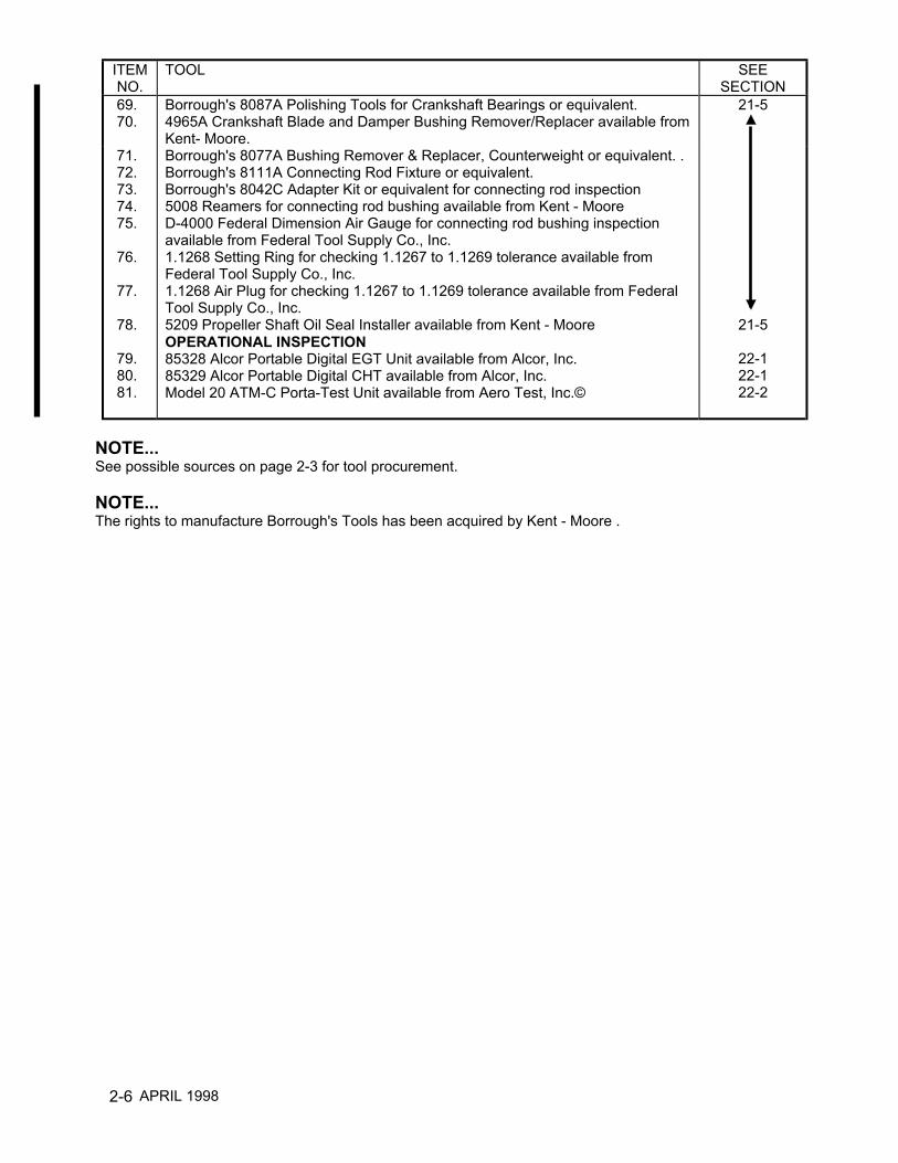
69. 70.
Borrough's 8087A Polishing Tools for Crankshaft Bearings or equivalent.4965A Crankshaft Blade and Damper Bushing Remover/Replacer available fromKent- Moore.
21-5
71. 72. 73. 74. 75.
76.
77.
78.
79. 80. 81.
Borrough's 8077A Bushing Remover & Replacer, Counterweight or equivalent. .Borrough's 8111A Connecting Rod Fixture or equivalent.Borrough's 8042C Adapter Kit or equivalent for connecting rod inspection5008 Reamers for connecting rod bushing available from Kent - MooreD-4000 Federal Dimension Air Gauge for connecting rod bushing inspectionavailable from Federal Tool Supply Co., Inc.1.1268 Setting Ring for checking 1.1267 to 1.1269 tolerance available fromFederal Tool Supply Co., Inc.1.1268 Air Plug for checking 1.1267 to 1.1269 tolerance available from FederalTool Supply Co., Inc.5209 Propeller Shaft Oil Seal Installer available from Kent - MooreOPERATIONAL INSPECTION85328 Alcor Portable Digital EGT Unit available from Alcor, Inc.85329 Alcor Portable Digital CHT available from Alcor, Inc.Model 20 ATM-C Porta-Test Unit available from Aero Test, Inc.©
21-5
22-122-122-2
NOTE...See possible sources on page 2-3 for tool procurement.
NOTE...The rights to manufacture Borrough's Tools has been acquired by Kent - Moore .
APRIL 1998
3-1
CHAPTER 3
SEALANTS AND LUBRICANTS
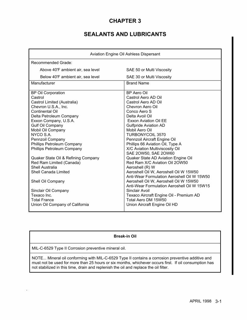
Aviation Engine Oil Ashless Dispersant
Recommended Grade:
Above 40'F ambient air, sea level
Below 40'F ambient air, sea level
SAE 50 or Multi Viscosity
SAE 30 or Multi ViscosityManufacturer Brand Name
BP Oil CorporationCastrolCastrol Limited (Australia)Chevron U.S.A., Inc.Continental OilDelta Petroleum CompanyExxon Company, U.S.A.Gulf Oil CompanyMobil Oil CompanyNYCO S.A.Pennzoil CompanyPhillips Petroleum CompanyPhillips Petroleum Company
Quaker State Oil & Refining CompanyRed Ram Limited (Canada)Shell AustraliaShell Canada Limited
Shell Oil Company
Sinclair Oil CompanyTexaco Inc.Total FranceUnion Oil Company of California
BP Aero OilCastrol Aero AD OilCastrol Aero AD OilChevron Aero OilConco Aero SDelta Avoil Oil Exxon Aviation Oil EEGulfpride Aviation ADMobil Aero OilTURBONYCOIL 3570Pennzoil Aircraft Engine OilPhillips 66 Aviation Oil, Type AX/C Aviation Multiviscosity OilSAE 2OW50, SAE 2OW60Quaker State AD Aviation Engine OilRed Ram X/C Aviation Oil 2OW50Aeroshell (R) WAeroshell Oil W, Aeroshell Oil W 15W50Anti-Wear Formulation Aeroshell Oil W 15W50Aeroshell Oil W, Aeroshell Oil W 15W50Anti-Wear Formulation Aeroshell Oil W 15W15Sinclair AvoilTexaco Aircraft Engine Oil - Premium ADTotal Aero DM 15W50Union Aircraft Engine Oil HD
Break-in Oil
MIL-C-6529 Type II Corrosion preventive mineral oil.
NOTE... Mineral oil conforming with MIL-C-6529 Type II contains a corrosion preventive additive andmust not be used for more than 25 hours or six months, whichever occurs first. If oil consumption hasnot stabilized in this time, drain and replenish the oil and replace the oil filter.
.
APRIL 1998
3-2
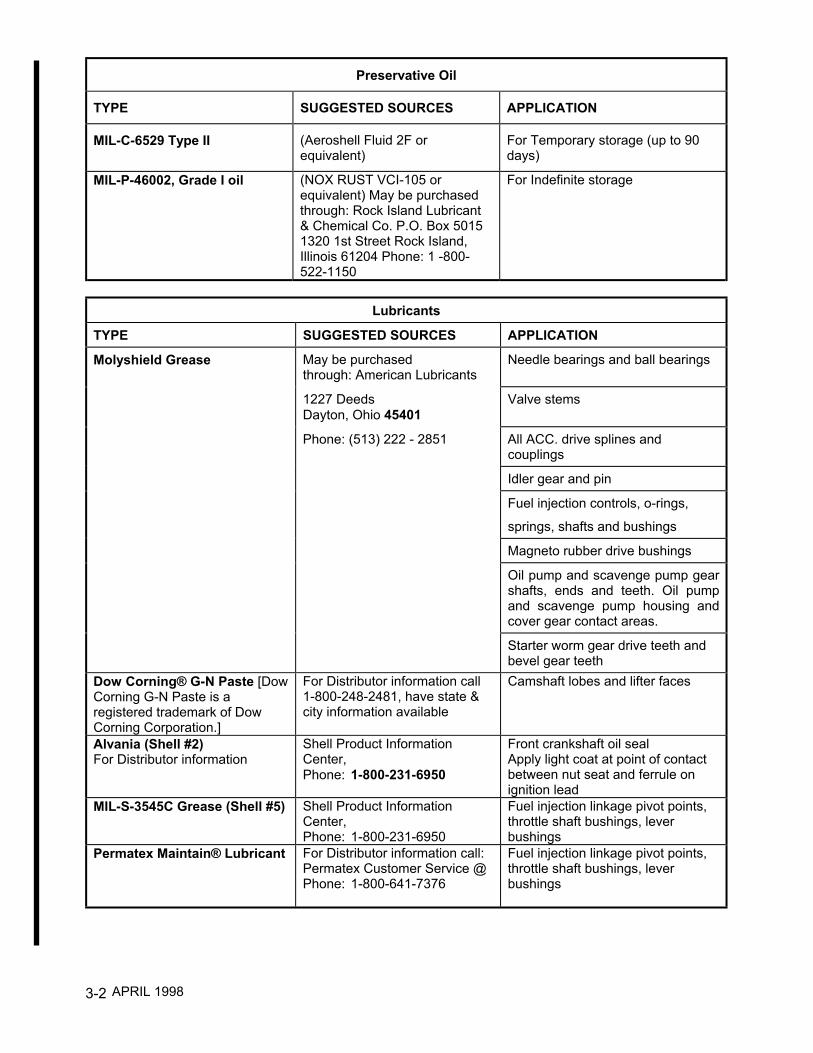
Preservative Oil
TYPE SUGGESTED SOURCES APPLICATION
MIL-C-6529 Type II (Aeroshell Fluid 2F orequivalent)
For Temporary storage (up to 90days)
MIL-P-46002, Grade I oil (NOX RUST VCI-105 orequivalent) May be purchasedthrough: Rock Island Lubricant& Chemical Co. P.O. Box 50151320 1st Street Rock Island,Illinois 61204 Phone: 1 -800-522-1150
For Indefinite storage
Lubricants
TYPE SUGGESTED SOURCES APPLICATION
Molyshield Grease May be purchasedthrough: American Lubricants
Needle bearings and ball bearings
1227 DeedsDayton, Ohio 45401
Valve stems
Phone: (513) 222 - 2851 All ACC. drive splines andcouplings
Idler gear and pin
Fuel injection controls, o-rings,
springs, shafts and bushings
Magneto rubber drive bushings
Oil pump and scavenge pump gearshafts, ends and teeth. Oil pumpand scavenge pump housing andcover gear contact areas.
Starter worm gear drive teeth andbevel gear teeth
Dow Corning® G-N Paste [DowCorning G-N Paste is aregistered trademark of DowCorning Corporation.]
For Distributor information call1-800-248-2481, have state &city information available
Camshaft lobes and lifter faces
Alvania (Shell #2)For Distributor information
Shell Product InformationCenter,Phone: 1-800-231-6950
Front crankshaft oil sealApply light coat at point of contactbetween nut seat and ferrule onignition lead
MIL-S-3545C Grease (Shell #5) Shell Product InformationCenter,Phone: 1-800-231-6950
Fuel injection linkage pivot points,throttle shaft bushings, leverbushings
Permatex Maintain® Lubricant For Distributor information call:Permatex Customer Service @Phone: 1-800-641-7376
Fuel injection linkage pivot points,throttle shaft bushings, leverbushings
APRIL 1998
3-3
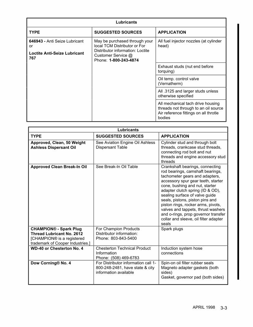
Lubricants
TYPE SUGGESTED SOURCES APPLICATION
646943 - Anti Seize Lubricantor
Loctite Anti-Seize Lubricant767
May be purchased through yourlocal TCM Distributor or ForDistributor information: LoctiteCustomer Service @Phone: 1-800-243-4874
All fuel injector nozzles (at cylinderhead)
Exhaust studs (nut end beforetorquing)
Oil temp. control valve(Vernatherm)
All .3125 and larger studs unlessotherwise specified
All mechanical tach drive housingthreads not through to an oil sourceAir reference fittings on all throtlebodies
LubricantsTYPE SUGGESTED SOURCES APPLICATIONApproved, Clean, 50 WeightAshless Dispersant Oil
See Aviation Engine Oil AshlessDispersant Table
Cylinder stud and through boltthreads, crankcase stud threads,connecting rod bolt and nutthreads and engine accessory studthreads
Approved Clean Break-In Oil See Break-In Oil Table Crankshaft bearings, connectingrod bearings, camshaft bearings,tachometer gears and adapters,accessory spur gear teeth, startercone, bushing and nut, starteradapter clutch spring (ID & OD),sealing surface of valve guideseals, pistons, piston pins andpiston rings, rocker arms, pivots,valves and tappets, thrust washersand o-rings, prop governor transfercollar and sleeve, oil filter adapterseals
CHAMPION® - Spark PlugThread Lubricant No. 2612[CHAMPION® is a registeredtrademark of Cooper Industries.]
For Champion ProductsDistributor information:Phone: 803-843-5400
Spark plugs
WD-40 or Chesterton No. 4 Chesterton Technical ProductInformationPhone: (508) 469-6783
Induction system hoseconnections
Dow Corning® No. 4 For Distributor information call 1-800-248-2481, have state & cityinformation available
Spin-on oil filter rubber sealsMagneto adapter gaskets (bothsides)Gasket, governor pad (both sides)
APRIL 1998
3-4
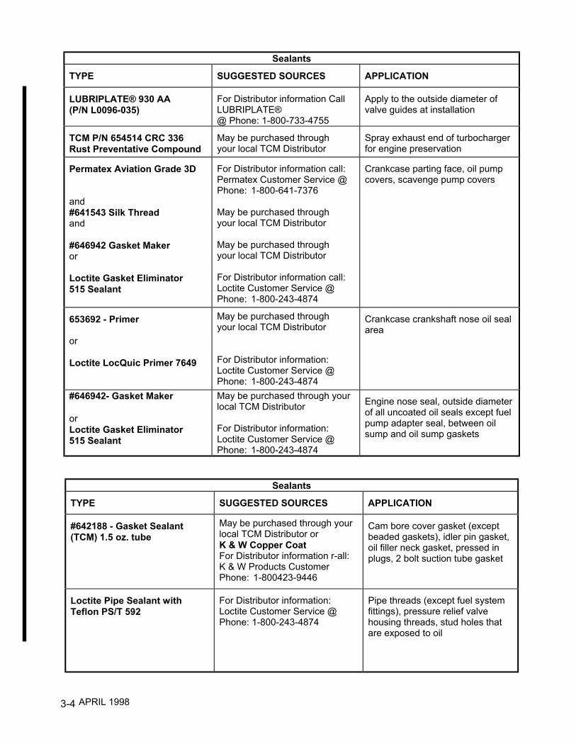
Sealants
TYPE SUGGESTED SOURCES APPLICATION
LUBRIPLATE® 930 AA(P/N L0096-035)
For Distributor information CallLUBRIPLATE®@ Phone: 1-800-733-4755
Apply to the outside diameter ofvalve guides at installation
TCM P/N 654514 CRC 336Rust Preventative Compound
May be purchased throughyour local TCM Distributor
Spray exhaust end of turbochargerfor engine preservation
Permatex Aviation Grade 3D
and#641543 Silk Threadand
#646942 Gasket Makeror
Loctite Gasket Eliminator515 Sealant
For Distributor information call:Permatex Customer Service @Phone: 1-800-641-7376
May be purchased throughyour local TCM Distributor
May be purchased throughyour local TCM Distributor
For Distributor information call:Loctite Customer Service @Phone: 1-800-243-4874
Crankcase parting face, oil pumpcovers, scavenge pump covers
653692 - Primer
or
Loctite LocQuic Primer 7649
May be purchased throughyour local TCM Distributor
For Distributor information:Loctite Customer Service @Phone: 1-800-243-4874
Crankcase crankshaft nose oil sealarea
#646942- Gasket Maker
orLoctite Gasket Eliminator515 Sealant
May be purchased through yourlocal TCM Distributor
For Distributor information:Loctite Customer Service @Phone: 1-800-243-4874
Engine nose seal, outside diameterof all uncoated oil seals except fuelpump adapter seal, between oilsump and oil sump gaskets
Sealants
TYPE SUGGESTED SOURCES APPLICATION
#642188 - Gasket Sealant(TCM) 1.5 oz. tube
May be purchased through yourlocal TCM Distributor orK & W Copper CoatFor Distributor information r-all:K & W Products CustomerPhone: 1-800423-9446
Cam bore cover gasket (exceptbeaded gaskets), idler pin gasket,oil filler neck gasket, pressed inplugs, 2 bolt suction tube gasket
Loctite Pipe Sealant withTeflon PS/T 592
For Distributor information:Loctite Customer Service @Phone: 1-800-243-4874
Pipe threads (except fuel systemfittings), pressure relief valvehousing threads, stud holes thatare exposed to oil
APRIL 1998

3-5
Sealants
TYPE SUGGESTED SOURCES APPLICATION
#646940 - F/I Sealant
or
Loctite Hydraulic Sealant 569
May be purchased throughyour local TCM Distributor
For Distributor information:Loctite Customer Service,Phone: 1-800-243-4874
All pipe thread fittings in fuelinjection system (use sparingly onmale threads only)
Miller StephensonMS 122/CO2 Spray
For Distributor information:Miller-Stephenson CustomerService,Phone: 1-800-992-2424
Ignition harness terminals atmagnetoblock end
Adhesives
TYPE SUGGESTED SOURCES APPLICATION
646941 High StrengthAdhesiveSealant or Loctite 271
653696 Primer or LoctiteLocQuic Primer 7471
May be purchased through yourlocal TCM Distributor
For Distributor information:Loctite Customer Service,Phone: 1-800-243-4874
Cylinder deck studs, squirt nozzles,fuel manifold valve diaphragm andplunger assembly, crankshaft noseseal retainer bolts, studs on coolantmanifold
649306 Sealant (optional646940) or Loctite AdhesiveSealant 222 (optional LoctiteHydraulic Sealant 569)
May be purchased throughyour local TCM
For Distributor information:Loctite Customer Service,Phone: 1-800-243-4874
Through stud holes on accessoryend of crankcase, manifold valve tobracket screws
3M Brand EC1252 White SpotPutty 3M Cylinder deck stud nuts, through
bolt nuts, magneto flanges, throttlebody and fuel metering unit
APRIL 1998
3-6
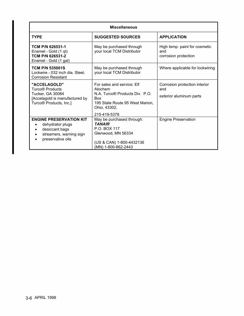
Miscellaneous
TYPE SUGGESTED SOURCES APPLICATION
TCM P/N 626531-1Enamel - Gold (1 qt)TCM P/N 626531-2Enamel - Gold (1 gal)
May be purchased throughyour local TCM Distributor
High temp. paint for cosmeticandcorrosion protection
TCM P/N 535001SLockwire -.032 inch dia. Steel,Corrosion Resistant
May be purchased throughyour local TCM Distributor
Where applicable for lockwiring
"ACCELAGOLD"Turco® ProductsTucker, GA 30084[Accelagold is manufactured byTurco® Products, Inc.]
For sales and service: ElfAtochemN.A. Turco® Products Div. P.O.Box195 State Route 95 West Marion,Ohio, 43302,
215-419-5376
Corrosion protection interiorand
exterior aluminum parts
ENGINE PRESERVATION KIT• dehydrator plugs• desiccant bags• streamers, warning sign• preservative oils
May be purchased through:TANAIRP.O. BOX 117Glenwood, MN 56334
(US & CAN) 1-800-4432136(MN) 1-800-862-2443
Engine Preservation
APRIL 1998
4-1
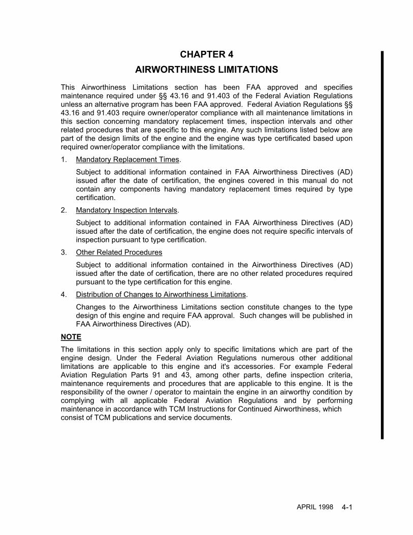
CHAPTER 4AIRWORTHINESS LIMITATIONS
This Airworthiness Limitations section has been FAA approved and specifiesmaintenance required under §§ 43.16 and 91.403 of the Federal Aviation Regulationsunless an alternative program has been FAA approved. Federal Aviation Regulations §§43.16 and 91.403 require owner/operator compliance with all maintenance limitations inthis section concerning mandatory replacement times, inspection intervals and otherrelated procedures that are specific to this engine. Any such limitations listed below arepart of the design limits of the engine and the engine was type certificated based uponrequired owner/operator compliance with the limitations.1. Mandatory Replacement Times.
Subject to additional information contained in FAA Airworthiness Directives (AD)issued after the date of certification, the engines covered in this manual do notcontain any components having mandatory replacement times required by typecertification.
2. Mandatory Inspection Intervals.Subject to additional information contained in FAA Airworthiness Directives (AD)issued after the date of certification, the engine does not require specific intervals ofinspection pursuant to type certification.
3. Other Related ProceduresSubject to additional information contained in the Airworthiness Directives (AD)issued after the date of certification, there are no other related procedures requiredpursuant to the type certification for this engine.
4. Distribution of Changes to Airworthiness Limitations.Changes to the Airworthiness Limitations section constitute changes to the typedesign of this engine and require FAA approval. Such changes will be published inFAA Airworthiness Directives (AD).
NOTEThe limitations in this section apply only to specific limitations which are part of theengine design. Under the Federal Aviation Regulations numerous other additionallimitations are applicable to this engine and it's accessories. For example FederalAviation Regulation Parts 91 and 43, among other parts, define inspection criteria,maintenance requirements and procedures that are applicable to this engine. It is theresponsibility of the owner / operator to maintain the engine in an airworthy condition bycomplying with all applicable Federal Aviation Regulations and by performingmaintenance in accordance with TCM Instructions for Continued Airworthiness, whichconsist of TCM publications and service documents.
APRIL 1998

4-2
INTENTIONALLY
LEFT
BLANK
5-1
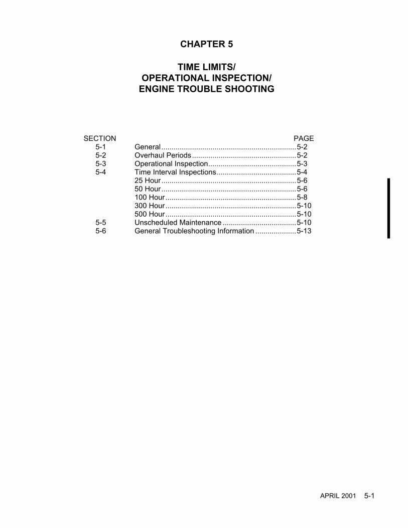
CHAPTER 5
TIME LIMITS/OPERATIONAL INSPECTION/
ENGINE TROUBLE SHOOTING
SECTION PAGE5-1 General..................................................................5-25-2 Overhaul Periods...................................................5-25-3 Operational Inspection...........................................5-35-4 Time Interval Inspections.......................................5-4
25 Hour..................................................................5-650 Hour..................................................................5-6100 Hour................................................................5-8300 Hour................................................................5-10500 Hour................................................................5-10
5-5 Unscheduled Maintenance ....................................5-105-6 General Troubleshooting Information ....................5-13
APRIL 2001

5-2
5-1 GENERAL
The scheduled inspection and maintenance described in this section must be complied with inaddition to all aircraft manufacturer and accessory manufacturer inspection and maintenancerequirements. This manual does not contain inspection or maintenance requirements forsupplemental type certificated engines, components or systems. Such information must beobtained from the supplemental type certificate holder.
Safety, efficiency and engine service life is predicated on compliance with the aircraft and enginemanufacturer's required instructions, inspections and maintenance schedule. The owner/operatoris primarily responsible for maintaining the engine in an airworthy condition, including compliancewith applicable Airworthiness Directives as specified in Part 39 of the Federal Aviation Regulations(FAR); reference FAR 91.163. The owner/operator is responsible for assuring the engine meetsthe conformity requirements as specified by the original Type Certificate (TC) or any SupplementalType Certificate (STC) that may apply to modifications or alterations accomplished after theissuance of the original TC.
NOTE…Engine operational inspection must be performed before and after any 50 or 100-hourinspections or maintenance in accordance with "Operational Inspection" requirements described inthis Chapter.
During engine 50 and 100-hour inspections, if engine components must be replaced or repaired,refer to the applicable system maintenance chapter. Corrections and adjustments will be found inthe individual system chapters.
WARNINGWhen performing any inspection or maintenance, always treat the engine as if theignition switch was on. Do not stand or allow anyone else to stand within the arc ofthe propeller. A loose or broken wire or a component malfunction could cause theengine and propeller to rotate and/or start.
Engines operated in extremely humid locations or in exceptionally cold, damp climates or coastalareas may require more frequent inspections. If the engine is operated in excess of 100 hours peryear, the engine should be inspected at each 100-hour interval in addition to an annual inspection.
5-2 OVERHAUL PERIODEngine Model Overhaul Period
I0-550-A, B, C Permold Series ................................................ 1700 HOURS or 12YearsI0-550-G, N, P & R Permold Series......................................... 2000 HOURS or 12Years
NOTE…Overhaul periods for the engine include all engine accessories.
APRIL 2001

5-3
5-3 OPERATIONAL INSPECTIONAn operational inspection must be performed prior to and after 50/100-hour inspections.
STARTINGStart engine using the starting procedure given in the airframe manufacturers Airplane FlightManual (AFM).
Oil Pressure - Check, If no oil pressure is noted within 30 seconds, shut engine down andinvestigate.
OPERATIONAL CHECK LIST
Check and record the following system data :
Starter................................................................................................................................__________*Record RPM Drop for each magneto at 1700 (150 RPM MAXIMUM AND 50 RPM SPREAD MAXIMUM) .........................................__________*Propeller Operation at 1700 ............................................................................................__________*Or as specified in aircraft manufacturer's instructions.Increase engine to full power and record:Manifold Pressure .............................................................................................................__________RPM...................................................................................................................................__________Fuel Flow...........................................................................................................................__________Oil Pressure.......................................................................................................................__________Oil Temperature ................................................................................................................__________Cylinder Head Temperature..............................................................................................__________Alternator Output...............................................................................................................__________Reduce engine to idle and record:Manifold Pressure .............................................................................................................__________RPM...................................................................................................................................__________Oil Pressure.......................................................................................................................__________Oil Temperature ................................................................................................................__________Cylinder Head Temperature..............................................................................................__________Magneto System Grounding Check..................................................................................__________
CAUTION…The magneto system grounding check must be accomplished at idle RPM only.Damage to the engine may result at engine speeds above idle RPM.
With engine speed at idle rpm, quickly turn both magnetos off then back on. The engine shouldcease running momentarily indicating both magnetos are properly grounded. If engine continuesto run, one or both magneto ground circuits is faulty and must be repaired prior to furtheroperation.
Slowly move mixture control to IDLE CUT OFF and record:Mixture RPM Rise ( 25 to 50 RPM ) ............................................................................... __________
APRIL 1998

5-4
Positive Fuel Cutoff ........................................................................................................__________When propeller stops rotating, place ignition switch, master switch and fuel selector in off position.
TEST OPERATING LIMITSRPM:
MODEL RecommendedMin. for Idle
Recommended Max.for Cruising
Rated MaximumContinuous Operation
I0-550-A 600 RPM 225 BHP @ 2500 300 BHP @ 2700 RPM I0-550-B 600 RPM 235 HP @ 2500 300 BHP @ 2700 RPM I0-550-C 600 RPM 235 HP @ 2500 300 BHP @ 2700 RPM I0-550-G 600 RPM 240 HP @ 2500 280 BHP @ 2500 RPMI0-550-N,P,R 600 RPM 240 HP @ 2500 310 BHP @ 2700 RPM
NOTE: May not be obtainable with aircraft static.
Manifold Air Pressure at Idle (Inches Hg) Max.............................................................18.5
Fuel - aviation gasoline - minimum grade ..............................100LL (Blue) or 100 (Green)
Fuel Flow at Full Throttle (Lbs./hr.) MODEL POUNDS PER HOUR GALLONS PER HOUR I0-550-A 142-150 24.2-25.6 I0-550-B 146-156 24.9-26.6 I0-550-C 152-160 25.9-27.3 I0-550-G 125-130 21.3-22.1 I0-550-N,P,R 150-160 25.6-27.3
Metered Fuel Pressure MODEL At Idle At Full Throttle I0-550-A 3.9-4.5 17.7-20.0 I0-550-B 3.9-4.5 16.5-18.4 I0-550-C 3.9-4.5 17.6-19.6 I0-550-G 3.9-4.5 14.7-16.0 I0-550-N,P,R 3.9-4.5 19.0-21.3
Unmetered Fuel Pressure MODEL At Idle At Full Throttle I0-550-A 8.0-10.0 32.0-36.0 I0-550-B 8.0-10.0 29.2-36.2 I0-550-C 8.0-10.0 31.6-37.8 I0-550-G 8.0-10.0 22.0-26.0 I0-550-N,P,R 8.0-10.0 28.0-32.0
APRIL 2001

5-5
Mixture Rise at Idle Cutoff-RPM ................................................................................ 25-50 Oil Temperature Minimum for takeoff ...................................................................................................75º F. Limit .........................................................................................................................240º F. Recommended operational range................................................................. 170º - 220º F. Oil Pressure Idle, minimum psi ............................................................................................................ 10 Normal operation, psi............................................................................................... 30 - 60 Max. (Oil Cold) .............................................................................................................. 100 Oil Sump Capacity (Quarts)
IO-550-A, B, C & R ...................................................................................................... 12IO-550-G & N ................................................................................................................. 8IO-550-P ....................................................................................................................... 10
Magneto Drop (Max.) ........................................................................................... 150 RPM Magneto Spread (Max.) ......................................................................................... 50 RPM Cylinder head temperaturewith Bayonet Thermocouple (Limit) ...........................................................................460°F Recommended Operational Maximum ......................................................................420°F
5-4 TIME INTERVAL INSPECTIONS
Engine mounted accessories not supplied by TCM may require servicing at specific intervals;some of these are alternators, pneumatic pumps, air/oil separators and stand-by generators. Referto the instructions provided by the aircraft manufacturer, accessory manufacturer or STC holderfor detailed information.
CAUTION…New, rebuilt and overhauled engines or engines that have had overhauled or newcylinders and new piston rings installed must be given a 100-hour inspection after 25 hours ofoperation.
Oil and Filter Change Interval ........................................................................... 50 hoursOr six months, whichever comes first
.CAUTION…Use only TCM approved oils. See TCM approved oils in chapter 3, “Table of Sealantsand Lubricants.”
APRIL 2001

5-6
25-HOUR INSPECTION
NOTE…Research and comply with all applicable Service Publications and Airworthiness Directives.
1. After the first 25 hours of operation on new, rebuilt or overhauled engines, perform a complete100-hour inspection. Drain the oil used for engine break-in. If engine oil consumption has stabilized,service the engine with TCM approved oil. If oil consumption has not stabilized, service engine witha mineral oil conforming to MIL-C-6529 Type II.
NOTE…Mineral oil conforming to MIL-C-6529 Type II is a straight mineral oil with a corrosionpreventive additive. This oil must not be operated in excess of 25 hours or 6 months, whicheveroccurs first. If oil consumption has not stabilized within the first 25 hours of engine operation, drainand replenish the oil and replace the filter.
Approved Oil Grade: All Temperatures .............................. TCM Approved Multi ViscosityBelow 40° F. Ambient Air (Sea Level ).............................. TCM Approved SAE 30 or Multi ViscosityAbove 40° F. Ambient Air (Sea Level ) .............................. TCM Approved SAE 50 or Multi Viscosity
2. Visually inspect the engine and nacelle for fuel, oil leaks and other discrepancies. 3. Correct any discrepancies noted during this inspection prior to returning the engine to service
50-HOUR INSPECTION
NOTE…Research and comply with any applicable Service Publications and AirworthinessDirectives.
1. Thoroughly inspect the engine for any signs of leakage. Clean engine exterior by spraying orbrushing with a flame resistant solvent used for general cleaning of engine parts.
NOTE…Any environmentally hazardous materials used in cleaning must be caught and disposed ofin accordance with Environmental Protection Agency regulations.
CAUTION…Do not use any alkaline cleaning solutions for external engine cleaning, these solutionswill remove the “alodized" finish of aluminum parts.
CAUTION…Do not use Kerosene or Gasoline for cleaning.
2. A pre-inspection operational run-up must be performed. See "Operational Inspection" of thischapter.
(a) Record the engine operating parameters.(b) Verify the recorded parameters meet the published specifications for the engine as provided inthe aircraft or engine manufacturer's Maintenance, Operator's and Overhaul Manuals.
After the operational inspection, inspect, isolate and repair any leaks found.
3. Reference the applicable Airplane Flight Manual for operational values.
APRIL 1998

5-7
4. Remove and inspect induction air filter. Clean or replace as instructed by the filtermanufacturer. Inspect induction system ducts, seals and gaskets for condition, deteriorationand obstructions in accordance with the aircraft manufacturer's instructions. With induction airfilter installed:
(a) Verify the induction air filter retainer is properly installed and the attaching hardware issecure in accordance with the aircraft manufacturer's instructions.
(b) Replace any questionable components as required in accordance with the aircraftmanufacturer's instructions.
(c) Inspect all engine controls for proper travel, freedom of movement, wear, correct riggingand correct attachment in accordance with the aircraft manufacturer's instructions.
CAUTION…Failure to properly install the induction air filter will result in unfiltered air beingingested into the engine which will accelerate engine wear and reduce engine service life.
5. Inspect induction air box for security and deterioration in accordance with the aircraftmanufacturer's instructions.
WARNING
Insure the fuel selector is in the off position prior to servicing fuel filters.
6. Drain the fuel filter and if sediment was noted, remove it. Service as required and reinstall inaccordance with the aircraft manufacturer's instructions.
7. Visually inspect engine and nacelle for fuel, oil leaks and other discrepancies. 8. Drain engine oil. During engine oil change, oil must be drained into an appropriate container
and disposed of properly. Reinstall oil drain plug with new gasket, torque and safety. 9. Remove oil filter. Inspect filter element. See "Oil Filter Element Inspection, Oil Analysis and
Spectrographic Oil Analysis" in chapter 7, “Servicing Fluids.” 10. Place a thin film of Dow Corning® DC-4 compound on new oil filter gasket. Install new oil filter.
Torque filter to values as directed by filter manufacturer and safety wire. 11. Inspect all induction system or cylinder drain(s) for clogging or restriction. 12. Inspect ignition leads for chafing, deterioration and proper routing. 13. Visually inspect magnetos for condition. Inspect, repair and adjust as required if magneto drop
or spread was not within published limits. 14. Correct all discrepancies noted .
APRIL 1998

5-8
WARNINGOperation of a malfunctioning engine can result in additional engine damage, bodilyinjury or death.
15. At the completion of any maintenance event the engine must be given a complete andthorough operational run-up. A test flight will be required if any engine adjustments have beenmade which affect flight characteristics or operation; this test flight is required by FAR 91.167.
(a) Record all engine parameters.(b) Verify recorded parameters are within the specifications published for the engine and
aircraft.
WARNINGFailure to identify and correct fuel or oil leaks can result in engine/nacelle fire, lossof engine power, engine failure, bodily injury or death.
16. Correct any discrepancies noted during operational run-up prior to returning aircraft to service.
100-HOUR INSPECTION
NOTE…Research and comply with the Service Publications and Airworthiness Directives.
In addition to the items listed in 50 Hour inspection, the following inspections and maintenancemust be performed.
1. Drain engine oil. Reinstall oil drain plug with new gasket, torque and safety. 2. Inspect the cylinder barrels and cylinder heads for cracks, leaks rust and pitting. Inspect
cylinder head and barrel cooling fins for any restriction of cooling airflow. 3. Inspect all inner cylinder and peripheral baffling for correct installation, proper positioning,
deterioration and missing or broken sections. 4. Perform a cylinder compression test in accordance with chapter 19 5. Inspect the entire engine, accessory section and nacelle for indications of fuel or oil leaks.
Inspect all wiring, fluid lines, hoses and electrical connections for proper routing, support andevidence of deterioration.
6. Visually inspect all cylinder and accessory to engine attaching hardware for security.Visually inspect airframe to engine connections for security and corrosion.
7. Inspect the induction and exhaust system for leaks, cracks, deterioration, broken, missing or
loose brackets, clamps and hardware. 8. Insure magneto to engine timing is within specifications in accordance with chapter 12 .
CAUTION…Magnetos using riveted type impulse coupling require repetitive 100-hour inspectionin accordance with the manufacturer’s instructions.
APRIL 1998
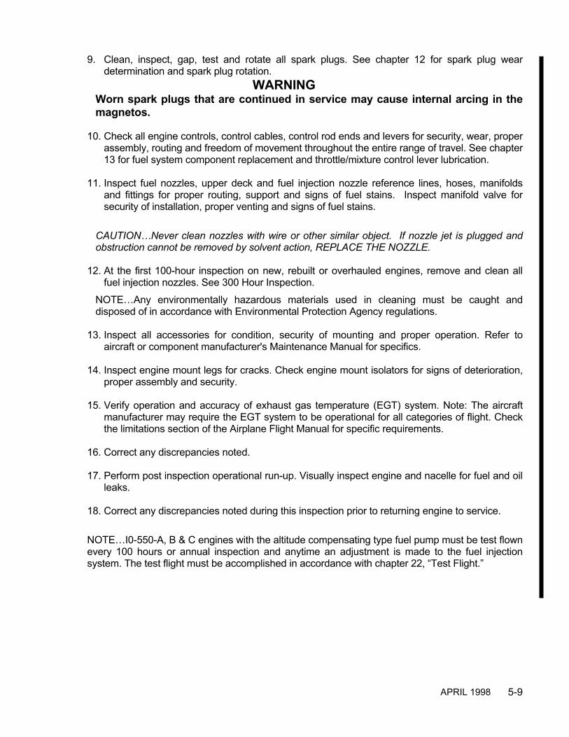
5-9
9. Clean, inspect, gap, test and rotate all spark plugs. See chapter 12 for spark plug weardetermination and spark plug rotation.
WARNINGWorn spark plugs that are continued in service may cause internal arcing in themagnetos.
10. Check all engine controls, control cables, control rod ends and levers for security, wear, properassembly, routing and freedom of movement throughout the entire range of travel. See chapter13 for fuel system component replacement and throttle/mixture control lever lubrication.
11. Inspect fuel nozzles, upper deck and fuel injection nozzle reference lines, hoses, manifoldsand fittings for proper routing, support and signs of fuel stains. Inspect manifold valve forsecurity of installation, proper venting and signs of fuel stains.
CAUTION…Never clean nozzles with wire or other similar object. If nozzle jet is plugged andobstruction cannot be removed by solvent action, REPLACE THE NOZZLE.
12. At the first 100-hour inspection on new, rebuilt or overhauled engines, remove and clean all
fuel injection nozzles. See 300 Hour Inspection.NOTE…Any environmentally hazardous materials used in cleaning must be caught anddisposed of in accordance with Environmental Protection Agency regulations.
13. Inspect all accessories for condition, security of mounting and proper operation. Refer toaircraft or component manufacturer's Maintenance Manual for specifics.
14. Inspect engine mount legs for cracks. Check engine mount isolators for signs of deterioration,
proper assembly and security. 15. Verify operation and accuracy of exhaust gas temperature (EGT) system. Note: The aircraft
manufacturer may require the EGT system to be operational for all categories of flight. Checkthe limitations section of the Airplane Flight Manual for specific requirements.
16. Correct any discrepancies noted. 17. Perform post inspection operational run-up. Visually inspect engine and nacelle for fuel and oil
leaks. 18. Correct any discrepancies noted during this inspection prior to returning engine to service.
NOTE…I0-550-A, B & C engines with the altitude compensating type fuel pump must be test flownevery 100 hours or annual inspection and anytime an adjustment is made to the fuel injectionsystem. The test flight must be accomplished in accordance with chapter 22, “Test Flight.”
APRIL 1998

5-10
300-HOUR INSPECTIONIn addition to the items listed for 100-hour inspections, perform the following inspection andmaintenance every 300 hours of engine operation.Remove and clean all fuel nozzles by soaking in lacquer thinner, acetone or methyl ethyl ketone(MEK). Fuel nozzles must be cleaned every 300-hours and annual inspection.
500-HOUR INSPECTIONIn addition to the items listed for 100-hour inspections, perform the following inspections andmaintenance every 500 hours of engine operation.
1. Magnetos require a thorough, detailed inspection. Refer to the applicable service andoverhaul information published by the manufacturer of the magneto. Magnetos must beoverhauled or replaced at the same intervals as the engine. TCM magnetos must beoverhauled or replaced every four years regardless of total operating hours since lastoverhaul or replacement.
2. Engine mounted accessories not supplied by TCM such as alternators, stand-by generators,
etc., may require servicing at specific intervals. Refer to the instructions provided by theaircraft manufacturer, accessory manufacturer or STC holder for detailed information.
3. TCM gear driven alternators require inspection and testing at 500-hour intervals. Refer to the
applicable alternator manufacturer's instructions. See "Related Publications" in theIntroduction section of this manual.
ANNUAL INSPECTIONPerform all requirements of 25, 50, 100, 200, 300 hour and any calendar inspections due.Comply with any 500 hour inspections that will come due before the next regularly scheduledmaintenance event.
5-5 UNSCHEDULED MAINTENANCEUnscheduled maintenance events include but are not limited to:
PROPELLER STRIKESA propeller strike is any incident, whether or not the engine is operating, that requires repair to thepropeller or any incident while the engine is operating in which the propeller makes contact withany object that results in a loss of engine RPM. Propeller strikes against the ground or any object,can cause engine and component damage even though the propeller may continue to rotate. Thisdamage can result in engine failure.When the propeller is damaged by a small object during operation, such as a small stone,inspection and repair must be accomplished in accordance with the propeller manufacturer'spublished instructions. Any time damage from an object strike requires propeller removal forrepairs the incident is considered a propeller strike.Following any propeller strike a complete engine disassembly and inspection is mandatory andmust be accomplished prior to further operation. Inspect all engine accessories in accordancewith the manufacturer's instructions.
APRIL 1998

5-11
HYDRAULIC LOCKGeneral InformationHydraulic lock is defined as a condition in which a volume of liquid, equal to or greater than theclearance volume of the combustion chamber is present in the cylinder during starting.Incompressible liquid restricts piston travel during the compression stroke. Damage occurs afterthe preceding cylinder or cylinders in the firing order have fired providing the required force to drivethe piston of the fluid filled cylinder through the compression stroke.Hydraulic locks in horizontally opposed aircraft engines are due to excess fuel accumulation in theinduction system and/or cylinder assembly or failure to properly drain preservation oil.Damage from a hydraulic lock can be extensive. Engine components such as connecting rods,cylinder assemblies, pistons, piston pins, crankcase and crankshaft can be damaged due tooverstress.In the event the operator starts an over-primed/flooded engine, hydraulic lock may result.Indications of hydraulic lock are difficult to detect since the engine will not normally exhibit anyunusual operation once the fuel-air mixture stabilizes. Therefore, the operator must be cognizantof the fact that a hydraulic lock can occur during an attempt to start an over-primed/floodedengine.In the event of a hydraulic lock perform the following inspection:
1. Remove all cylinders and connecting rods in accordance with the current TCM OverhaulManual. Inspect the connecting rods in accordance with the current TCM Overhaul Manual.
2. If all connecting rods meet the criteria specified by TCM, reassemble the engine in accordance
with the current TCM Overhaul Manual.
3. If any connecting rod does not meet TCM specifications, remove and disassemble the engineto allow inspection of the crankcase and crankshaft in accordance with the current TCMOverhaul Manual. Replace any part that does not meet TCM specifications. Replace eachnon-conforming connecting rod and its associated piston, piston pin and cylinder assembly.
CAUTION…Any parts that require replacement must be destroyed to prevent future installation.
4. Clean, inspect, repair, reassemble and test the engine in accordance with the current TCMOverhaul Manual.
ENGINE OVERSPEED INSPECTIONEngine operation at engine speeds in excess of rated RPM limitations can cause damage to theengine and can result in subsequent engine failure.If an engine overspeed occurs determine the cause for overspeed and correct it. The airframemanufacturer's instructions on engine and propeller overspeed must also be referenced andfollowed.If an engine overspeed occurs use the following procedures:RPM TO 30001. Less than one minute - No action required
APRIL 1998

5-12
2. More than one minute - Proceed as follows:a. Drain oil through a fine mesh screen and inspect for debris.b. Remove oil filter and inspect filter element for debris.c. Remove and inspect inside of rocker covers for debris. Inspect valve stem (keeper
grooves) and valve keepers for condition, security and proper installation. Inspect valvesprings, rocker arms, spring retainers, rotocoils, pushrods, etc.
d. Perform a borescope inspection on all cylinders.e. If no discrepancies are noted, re-service engine, perform operational inspection and
correct any discrepancies noted prior to returning the engine to service.f. If discrepancies are found a decision must be made, based on the evidence, as to the
extent of the corrective action required.
RPM TO 3300In addition to action required for "" above proceed as follows:1. Remove all cylinder assemblies including rods and pistons. Clean, inspect, repair or replace all components removed from the engine in accordance with the
manufacturer's current overhaul manual. Using new connecting rod bolts and nuts,reassemble, service and test the engine in accordance with the current overhaul manual.
2. After five and ten hours of engine operation remove oil filter and inspect filter element fordebris.
RPM EXCEEDING 33001. Remove engine and clearly identify "Removal For Overspeed".2. Engine and accessories must be completely overhauled in accordance with the respective
manufacturer's current overhaul instructions or replaced with certified airworthy components.
LIGHTNING STRIKEIt is impossible to assess internal damage that may result from a lightning strike. A completedisassembly and inspection of the engine must be accomplished in accordance with the currentoverhaul manual.
CONTAMINATED FUEL INCORRECT FUEL GRADEIf the aircraft is inadvertently serviced with the wrong grade of fuel or jet fuel, the fuel must becompletely drained and the tank properly serviced.Any engine operated on fuel of lower grade than approved for the engine, or jet fuel, must becompletely disassembled, cleaned, inspected, repaired, reassembled and tested in accordancewith the manufacturer's current overhaul manual.
APRIL 1998

5-13
5-6 GENERAL TROUBLESHOOTING INFORMATIONThe troubleshooting chart which follows discusses symptoms which can be diagnosed and interprets theprobable causes and the appropriate corrective actions to be taken.Troubleshooting for individual systems follow the engine troubleshooting chart.
WARNINGAny attempt by unqualified personnel to adjust, repair or replace any parts, may result inengine malfunction or failure.
WARNINGOperation of a malfunctioning engine can cause further damage to a disabledcomponent and possible injury to personnel.
ENGINE TROUBLESHOOTINGTROUBLE PROBABLE CAUSE CORRECTIONEngine Will Not Start No fuel to engine Service aircraft fuel system in
accordance with the airframemanufacturer's instructions
Improper starting procedure Refer to the airframemanufacturer's Airplane FlightManual (AFM) for engine startingprocedures. Check for performanceof each item
Cylinder overprimed. Engineflooded
Allow fuel to drain from intakesystem. WARNING…Starting anengine with a flooded intakesystem may result in hydrostaticlock and subsequent enginemalfunction.
Induction system leak Torque or replace loose ordamaged hose connection
Excessive Starter slippage Replace starter adapterFuel system malfunction Isolate cause and correctIgnition system malfunction See "Ignition Troubleshooting
Engine Will Not RunAt Idling Speed
Fuel injection system improperlyadjusted
See "Fuel Injection SystemTroubleshooting
Air leak in intake manifold Torque loose connection or replacemalfunctioning part
Rough Idling Fuel injection system improperlyadjusted
Adjust fuel system in accordancewith chapter 22 "Fuel SystemAdjustment."
Mixture levers set for impropermixture
Adjust the manual mixture controlin accordance with the airframemanufacturer's Airplane FlightManual (AFM)
Fouled Spark Plugs Remove, clean and adjust gaps inaccordance with the spark plugmanufacturer's instructions
APRIL 1998

5-14
ENGINE TROUBLESHOOTING (continued)TROUBLE PROBABLE CAUSE CORRECTIONRough Idling (continued) Hydraulic tappets fouled Replace fouled tappets. Inspect
and clean oil filter at more frequentintervals
Burned or warped exhaustvalves worn seat, scored valveguides
Inspect, repair or replace cylinder.Replace any burned, warped orworn exhaust valves
Manifold valve vent obstruction Repair or replace manifold valveEngine Runs Too LeanAt Cruising Power
Improper manual leaningprocedure
Refer to the airframemanufacturer's Airplane FlightManual (AFM) for engine operatinginstructions
Fuel injection systemmaladjusted
Adjust fuel system in accordancewith chapter 22, "Fuel SystemAdjustment
Engine Runs Too RichAt Cruising Power
Restrictions in air intakepassages
Check passages and removerestrictions
Improper manual leaning offuel/Air mixture
See the airframe manufacturer'sAirplane Flight Manual (AFM) forcorrect leaning procedure
Engine Runs Too Lean Or TooRich At Throttle Setting OtherThan Cruise
Fuel injection systemmaladjusted
See "Fuel Injection SystemTroubleshooting”
Continuous Fouling OfSpark Plugs
Piston rings excessively worn orbroken
Replace rings. Replace cylinder ifdamaged
Piston rings are not seated Hone cylinder walls, replace ringsNOTE…Cylinder grinding andhoning must be done by a qualifiedFAA approved rework facility
Engine Runs Rough AtHigh Speed
Loose mounting bolts ordamagedmount pads
Torque mounting bolts. Replacemount pads
Plugged fuel nozzle jet Clean. Replace nozzle ifobstruction cannot be cleared bysolvent action. Never use wire orany other object to clear nozzle jet
Propeller out of balance Remove and repair in accordancewith airframe manufacturer'sinstructions
Ignition system malfunction See "Ignition Troubleshooting"Continuous Missing AtHigh Speed
Broken valve spring Inspect, repair or replace cylinder.Replace valve springs
APRIL 1998

5-15
ENGINE TROUBLESHOOTING (continued)TROUBLE PROBABLE CAUSE CORRECTIONContinuous Missing AtHigh Speed (continued)
Plugged fuel nozzle jet Clean. Replace nozzle ifobstruction cannot be cleared bysolvent action. Never use wire orany other object to clear nozzlejet
Burned or warped valve Inspect, repair or replacecylinder. Replace any burned,warped or worn exhaust valves
Hydraulic tappet dirty or worn Remove and replaceSluggish Operation AndLow Power
Throttle not full open Check and adjust linkage. SeeRigging of Mixture and ThrottleControls in the applicableairframe manufacturer'sinstructions
Restrictions in air intakepassages
Inspect air intake and removerestrictions
Ignition system malfunction See "Ignition Troubleshooting”Fuel injection systemmaladjusted
See "Fuel Injection SystemTroubleshooting”
High Cylinder HeadTemperature
Lean fuel/air mixture See the airframe manufacturer'sAirplane Flight Manual (AFM) forcorrect leaning procedure
Debris between cylinder fins Clean thoroughlyIncorrect engine timing Adjust engine timing in
accordance with chapter 12Exhaust system gas leakage Locate and correct in
accordance with the airframemanufacturer’s instructions
Exhaust valve leaking Repair cylinder. See chapter 19,“Cylinder assemblyMaintenance.”
Baffle seals leakingor mispositioned
Repair or replace baffle seals
APRIL 1998
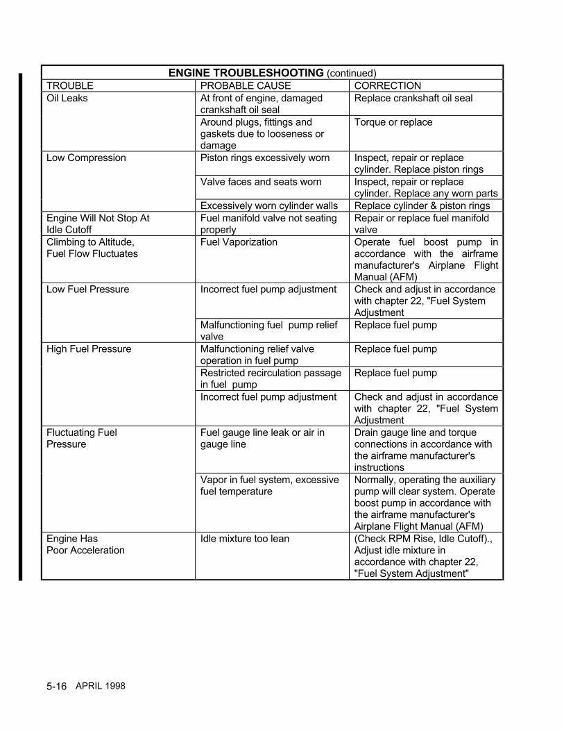
5-16
ENGINE TROUBLESHOOTING (continued)TROUBLE PROBABLE CAUSE CORRECTIONOil Leaks At front of engine, damaged
crankshaft oil sealReplace crankshaft oil seal
Around plugs, fittings andgaskets due to looseness ordamage
Torque or replace
Low Compression Piston rings excessively worn Inspect, repair or replacecylinder. Replace piston rings
Valve faces and seats worn Inspect, repair or replacecylinder. Replace any worn parts
Excessively worn cylinder walls Replace cylinder & piston ringsEngine Will Not Stop AtIdle Cutoff
Fuel manifold valve not seatingproperly
Repair or replace fuel manifoldvalve
Climbing to Altitude,Fuel Flow Fluctuates
Fuel Vaporization Operate fuel boost pump inaccordance with the airframemanufacturer's Airplane FlightManual (AFM)
Low Fuel Pressure Incorrect fuel pump adjustment Check and adjust in accordancewith chapter 22, "Fuel SystemAdjustment
Malfunctioning fuel pump reliefvalve
Replace fuel pump
High Fuel Pressure Malfunctioning relief valveoperation in fuel pump
Replace fuel pump
Restricted recirculation passagein fuel pump
Replace fuel pump
Incorrect fuel pump adjustment Check and adjust in accordancewith chapter 22, "Fuel SystemAdjustment
Fluctuating FuelPressure
Fuel gauge line leak or air ingauge line
Drain gauge line and torqueconnections in accordance withthe airframe manufacturer'sinstructions
Vapor in fuel system, excessivefuel temperature
Normally, operating the auxiliarypump will clear system. Operateboost pump in accordance withthe airframe manufacturer'sAirplane Flight Manual (AFM)
Engine HasPoor Acceleration
Idle mixture too lean (Check RPM Rise, Idle Cutoff).,Adjust idle mixture inaccordance with chapter 22,"Fuel System Adjustment"
APRIL 1998
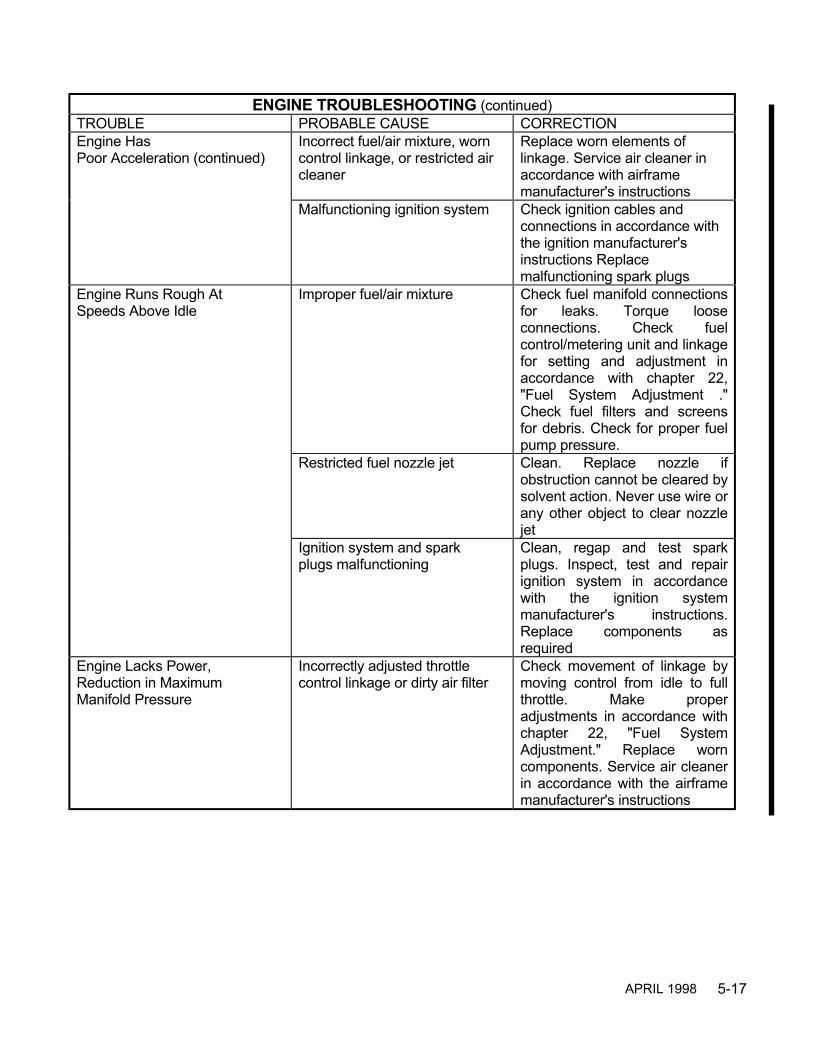
5-17
ENGINE TROUBLESHOOTING (continued)TROUBLE PROBABLE CAUSE CORRECTIONEngine HasPoor Acceleration (continued)
Incorrect fuel/air mixture, worncontrol linkage, or restricted aircleaner
Replace worn elements oflinkage. Service air cleaner inaccordance with airframemanufacturer's instructions
Malfunctioning ignition system Check ignition cables andconnections in accordance withthe ignition manufacturer'sinstructions Replacemalfunctioning spark plugs
Engine Runs Rough AtSpeeds Above Idle
Improper fuel/air mixture Check fuel manifold connectionsfor leaks. Torque looseconnections. Check fuelcontrol/metering unit and linkagefor setting and adjustment inaccordance with chapter 22,"Fuel System Adjustment ."Check fuel filters and screensfor debris. Check for proper fuelpump pressure.
Restricted fuel nozzle jet Clean. Replace nozzle ifobstruction cannot be cleared bysolvent action. Never use wire orany other object to clear nozzlejet
Ignition system and sparkplugs malfunctioning
Clean, regap and test sparkplugs. Inspect, test and repairignition system in accordancewith the ignition systemmanufacturer's instructions.Replace components asrequired
Engine Lacks Power,Reduction in MaximumManifold Pressure
Incorrectly adjusted throttlecontrol linkage or dirty air filter
Check movement of linkage bymoving control from idle to fullthrottle. Make properadjustments in accordance withchapter 22, "Fuel SystemAdjustment." Replace worncomponents. Service air cleanerin accordance with the airframemanufacturer's instructions
APRIL 1998

5-18
ENGINE TROUBLESHOOTING (continued)TROUBLE PROBABLE CAUSE CORRECTIONEngine Lacks Power,Reduction in MaximumManifold Pressure (continued)
Malfunctioning ignition systemcomponent
Inspect spark plugs for fouledelectrodes, heavy carbon deposits,erosion of electrodes, improperlyadjusted electrode gaps, andcracked porcelains. Test plugs forregular firing under pressure.Replace damaged or misfiringplugs. Gap spark plugs to sparkplug manufacturer's specifications.
Loose or damaged intakemanifold
Inspect entire manifold system forpossible leakage at connections.Replace damaged components,torque all connections and clampsto specifications
Fuel nozzles restricted Clean nozzles. Replace nozzle ifobstruction cannot be cleared bysolvent action. Never use wire orany other object to clear nozzle jet
Low Oil PressureIndication OnEngine Gauge
Insufficient oil in oil sump, oildilution or using improper gradeoil for prevailing ambienttemperature
Add oil, or change oil to properviscosity. Inspect for possible oildilution, repair as required
High oil temperature Malfunctioning oil temperaturecontrol valve in oil cooler; oil coolerrestriction. Replace valve and cleanoil cooler
Restricted oil filter. Leaking,damaged or loose oil lineconnections
Check for restricted lines, looseconnections, and for partiallyplugged oil filter. Replace oil filter.Clean parts, torque connections,and replace malfunctioning parts
Oil pressure gauge malfunction Check oil pressure gaugecalibration in accordance with theairframe manufacturer's instructions
Engine oil pressure maladjusted Adjust oil pressure in accordancewith chapter 22, "Oil PressureAdjustment”
APRIL 1998

5-19
ENGINE TROUBLESHOOTING (continued)TROUBLE PROBABLE CAUSE CORRECTIONLow Oil Pressure Indication OnEngine Gauge (continued)
Low oil supply. Oil viscosity toolow
Replenish. Drain and refill withcorrect viscosity
Malfunctioning oil pump Repair or replace oil pumpWeak or broken oil pressurerelief valve spring
Replace spring. Adjust oilpressure in accordance withchapter 22, "Oil PressureAdjustment."
High Oil Temperature Indication Prolonged ground operation Limit ground operation to aminimum
Malfunctioning gauge or bulbunit
Check wiring. Check bulb unit.Check gauge. Replacemalfunctioning parts inaccordance with the airframemanufacturer's instructions
FUEL INJECTIONTROUBLE PROBABLE CAUSE CORRECTIONFluctuating Fuel FlowIndications
Fuel vapor as a result of highambient temperatures
If not cleared with auxiliarypump, check for clogged vent infuel pump vapor separatorcover. Clean only with solvent,no wires. Refer to airframemanufacturer's instruction
Air in fuel flow gauge line. Leakat gauge connection
Repair leak and purge line.Refer to airframe manufacturer'sinstruction
Poor Idle Cutoff Engine getting fuel Check mixture control is in fullidle cutoff. Check auxiliary pumpis OFF. If neither, replacemanifold valve.
Unmetered Fuel Pressure tooHigh
Internal orifices plugged Clean internal orifices injectorpump. Refer to Fuel InjectionService Manual, Form X30593A
Unmetered Fuel Pressure Drop Relief valve stuck open Repair or replace fuel pumpVery High Idle And Full ThrottleFuel Pressure Present
Relief valve stuck closed Repair or replace fuel pump
No Fuel Pressure Check valve stuck open Repair or replace fuel pump
APRIL 1998

5-20
FUEL INJECTION (continued)TROUBLE PROBABLE CAUSE CORRECTION
Engine Will Not Start And NoFuel Flow Gauge Indication
No fuel to engine Check tank fuel level
Mixture control improperlyrigged
Check mixture control for properrigging. Refer to airframemanufacturer's instruction
Engine not primed Check auxiliary pump switchposition. Refer to airframemanufacturer's instruction
Selector valve in wrong position Position selector valve to MAINTANK position. Refer to airframemanufacturer's instruction
Engine Will Not Start WithFuel Flow Gauge Indication
Engine flooded Allow all fuel to drain from intakesystem.WARNING…Starting anengine with a flooded intakesystem may result inhydrostatic lock andsubsequent enginemalfunction
No fuel to engine Loosen one line at nozzle. If nofuel shows, with fuel flow ongauge, replace fuel manifoldvalve
Rough Idle Nozzle restricted Clean. Replace nozzle ifobstruction cannot be cleared bysolvent action. Never use wire orany other object to clear nozzlejet
APRIL 1998

5-21
FUEL INJECTION (continued)TROUBLE PROBABLE CAUSE CORRECTION
Rough Idle (continued) Improper idle mixture Adjust fuel mixture in accordancewith chapter 22, "Fuel SystemAdjustment”
Poor Acceleration Idle mixture incorrect Adjust fuel mixture in accordancewith chapter 22, "Fuel SystemAdjustment”
Unmetered fuel pressure toohigh
Lower unmetered fuel pressure.Adjust in accordance withchapter 22, "Fuel SystemAdjustment."
Worn linkage Replace worn elements oflinkage. in accordance with theairframe manufacturer'sinstruction
Engine Runs Rough Restricted nozzle Clean. Replace nozzle ifobstruction cannot be cleared bysolvent action. Never use wire orany other object to clear nozzlejet.
Improper mixture Adjust fuel mixture in accordancewith chapter 22, "Fuel SystemAdjustment
Low Fuel Flow Gauge Indication Restricted flow to metering unit Check for restriction betweenfuel pump and fuel metering unit
Inadequate flow from fuel pump Adjust engine-driven fuel pumpin accordance with chapter 22,"Fuel System Adjustment”
High Fuel Flow Gauge Indication Restricted flow beyond meteringvalve
Check for restricted nozzles orfuel manifold valve. Clean orreplace as required
Restricted recirculation passagein fuel pump
Replace engine driven fuel pump
APRIL 1998

5-22
INDUCTIONTROUBLE PROBABLE CAUSE CORRECTIONEngine Will Not Start Induction system intake
obstructedLocate and remove obstruction
Engine Will Not Run At IdlingSpeed
Induction system leakage See chapter 14
Engine Runs Too Rich At CruisePower
Restrictions in air intakepassages
Check air passages removerestriction
Sluggish Operation And LowPower
Throttle not opening wide Check and adjust controlconnections in accordance withthe airframe manufacturer’sinstructions.
IGNITIONTROUBLE PROBABLE CAUSE CORRECTIONEngine Fails To Start Ignition switch OFF or grounded
switch wiresTurn switch On. Check forgrounded wires
Spark plugs fouled, improperlygapped, or loose
Remove and clean. Adjust toproper gap in accordance withspark plug manufacturer'sspecifications. Torque sparkplugs in accordance withchapter 12
Magnetos improperly timed toengine
Refer to chapter 12, IgnitionTiming for timing procedures
Shorted condenser Replace condenser inaccordance with magnetomanufacturer's instructions
Magneto internal timing incorrector timed for opposite rotation
Install correctly timed magneto
Rough Idling Spark plugs fouled or improperlygapped
Clean spark plugs. Adjust toproper gap in accordance withspark plug manufacturer'sspecifications
Weak condenser Replace condenser inaccordance with magnetomanufacturer's instructions
Rough At Speeds Above Idle Loose or improperly gappedspark plugs
Adjust to proper gap inaccordance with spark plugmanufacturer's specifications.Torque spark plugs inaccordance with chapter 12
APRIL 1998
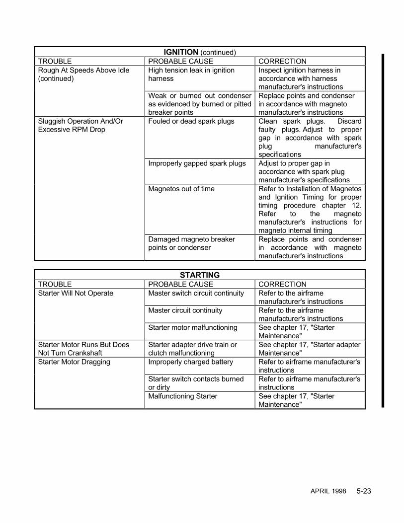
5-23
IGNITION (continued)TROUBLE PROBABLE CAUSE CORRECTIONRough At Speeds Above Idle(continued)
High tension leak in ignitionharness
Inspect ignition harness inaccordance with harnessmanufacturer's instructions
Weak or burned out condenseras evidenced by burned or pittedbreaker points
Replace points and condenserin accordance with magnetomanufacturer's instructions
Sluggish Operation And/OrExcessive RPM Drop
Fouled or dead spark plugs Clean spark plugs. Discardfaulty plugs. Adjust to propergap in accordance with sparkplug manufacturer'sspecifications
Improperly gapped spark plugs Adjust to proper gap inaccordance with spark plugmanufacturer's specifications
Magnetos out of time Refer to Installation of Magnetosand Ignition Timing for propertiming procedure chapter 12.Refer to the magnetomanufacturer's instructions formagneto internal timing
Damaged magneto breakerpoints or condenser
Replace points and condenserin accordance with magnetomanufacturer's instructions
STARTINGTROUBLE PROBABLE CAUSE CORRECTIONStarter Will Not Operate Master switch circuit continuity Refer to the airframe
manufacturer's instructionsMaster circuit continuity Refer to the airframe
manufacturer's instructionsStarter motor malfunctioning See chapter 17, "Starter
Maintenance"Starter Motor Runs But DoesNot Turn Crankshaft
Starter adapter drive train orclutch malfunctioning
See chapter 17, "Starter adapterMaintenance"
Starter Motor Dragging Improperly charged battery Refer to airframe manufacturer'sinstructions
Starter switch contacts burnedor dirty
Refer to airframe manufacturer'sinstructions
Malfunctioning Starter See chapter 17, "StarterMaintenance"
APRIL 1998

5-24
LUBRICATIONTROUBLE PROBABLE CAUSE CORRECTIONExcessive Oil Consumption Oil leakage Replace leaking oil lines, torque
loose connectionsGasket or seal leakage Replace gasket or oil sealsImproper seasonal weight orgrade oil
Service engine with proper oil,see chapter 7
Worn piston rings or valveguides
Inspect, repair or replacecylinder. Replace piston rings
Excessive crankcase pressure Stuck rings or worn piston ringsor cylinder. Valve guide leakageexcessive. Worn or leakingcrankshaft oil seal
High Oil Temperature Indication Low oil supply Replenish, see chapter 7Cooler air passages clogged Clean thoroughlyCooler core plugged Remove cooler and flush
thoroughlyThermostat damaged or heldopen by solid matter
Remove clean valve and seat. Ifstill inoperative, replace
Oil Viscosity too high Drain and refill with correctviscosity. See chapter 7
Prolonged ground operation Limit ground operation to aminimum. Refer to the airframemanufacturer's operatinginstructions
Malfunctioning gauge or bulbunit
Check wiring. Check bulb unit.Check gauge. Refer to theAirframe Manufacturer'sInstructions
Exhaust leak Replace malfunctioningcomponent, insure exhaustsystem is installed properly,replace any leaking gaskets
Low Oil Pressure Indication Low oil supply. Oil viscosity toolow
Replenish. Drain and refill withcorrect seasonal weight. Seechapter 7
Malfunctioning oil pump Replace pumpMalfunctioning pressure gauge Check gauge. Clean plumbing.
Replace if required inaccordance with the AirframeManufacturer's Instructions
Weak or broken oil pressurerelief valve spring
Replace spring. Adjust pressureto 30-60 psi. in accordance withchapter 22
APRIL 1998

5-25
CYLINDERSTROUBLE PROBABLE CAUSE CORRECTIONRough Idling Hydraulic tappets fouled See chapter 19, Cylinder
Assembly Maintenance"Hydraulic Tappets"
Burned or warped exhaustvalves, worn valve seats.Scored valve guides
See chapter 19, CylinderAssembly Maintenance"Cylinders"
Valve seats worn and leaking,piston rings worn or stuck in ringlands
See chapter 19, CylinderAssembly Maintenance"Cylinders"
High Cylinder HeadTemperature
Exhaust valve leaking, cylinderbaffles loose or bent. Coolingarea between cylinder finsobstructed
See chapter 19, CylinderAssembly Maintenance"Cylinders"
Exhaust gasket leaking Replace gasketValve seats worn and leaking,piston rings worn or stuck in ringlands
See chapter 19, CylinderAssembly Maintenance"Cylinders"
Baffle seals leakingor mispositioned
Repair or replace baffle seals
Low Compression Piston rings excessively worn See chapter 19, CylinderAssembly Maintenance"Cylinders"
Valve faces and seats worn See chapter 19, CylinderAssembly Maintenance"Cylinders"
Excessively worn cylinder walls See chapter 19, CylinderAssembly Maintenance"Cylinders"
Valve seats worn and leaking,piston rings worn or stuck in ringlands
See chapter 19, CylinderAssembly Maintenance"Cylinders"
Continuous Fouling Of SparkPlugs
Piston rings excessively worn orbroken
See chapter 19, CylinderAssembly Maintenance"Cylinders"
Piston rings not seated See chapter 19, CylinderAssembly Maintenance"Cylinders"
Cylinder has been overheated See chapter 19, CylinderAssembly Maintenance"Cylinders"
Cylinder bore out of round See chapter 19, CylinderAssembly Maintenance"Cylinders"
Valve seats worn and leaking,piston rings worn or stuck in ringlands
See chapter 19, CylinderAssembly Maintenance"Cylinders"
APRIL 1998
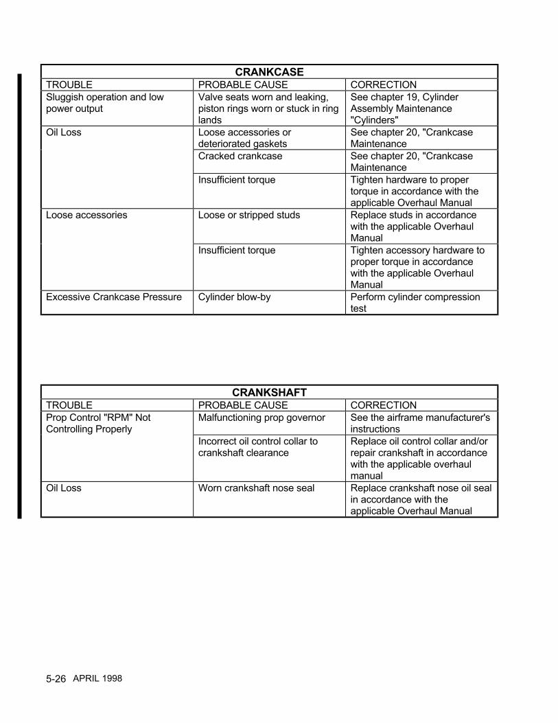
5-26
CRANKCASETROUBLE PROBABLE CAUSE CORRECTIONSluggish operation and lowpower output
Valve seats worn and leaking,piston rings worn or stuck in ringlands
See chapter 19, CylinderAssembly Maintenance"Cylinders"
Oil Loss Loose accessories ordeteriorated gaskets
See chapter 20, "CrankcaseMaintenance
Cracked crankcase See chapter 20, "CrankcaseMaintenance
Insufficient torque Tighten hardware to propertorque in accordance with theapplicable Overhaul Manual
Loose accessories Loose or stripped studs Replace studs in accordancewith the applicable OverhaulManual
Insufficient torque Tighten accessory hardware toproper torque in accordancewith the applicable OverhaulManual
Excessive Crankcase Pressure Cylinder blow-by Perform cylinder compressiontest
CRANKSHAFTTROUBLE PROBABLE CAUSE CORRECTIONProp Control "RPM" NotControlling Properly
Malfunctioning prop governor See the airframe manufacturer'sinstructions
Incorrect oil control collar tocrankshaft clearance
Replace oil control collar and/orrepair crankshaft in accordancewith the applicable overhaulmanual
Oil Loss Worn crankshaft nose seal Replace crankshaft nose oil sealin accordance with theapplicable Overhaul Manual
APRIL 1998

5-27
INTENTIONALLY
LEFT
BLANK
6-1
CHAPTER 6
Unpacking, Deinhibiting, Installationand Testing
Engine unpacking, deinhibiting, installation and testing must be performed in accordance with theinstructions in the I0-550-A,B,C,G, N, P and R Operation and Installation Manual, Form X30565 andthe airframe manufacturer’s instructions.
APRIL 2001

6-2
INTENTIONALLY
LEFT
BLANK
7-1
CHAPTER 7
SERVICING FLUIDS
SECTION PAGE7-1 Servicing, Oil .............................................................................7-27-2 Oil Filter Element Inspection .....................................................7-77-3 Spectrographic Oil Analysis ......................................................7-77-4 Servicing Fuel ...........................................................................7-9
FIGURE PAGE7-1 IO-550-A, B, C Oil Servicing Points ..........................................7-37-2 IO-550-G, N Oil Servicing Points ..............................................7-47-3 IO-550-P Oil Servicing Points ...................................................7-57-4 IO-550-R Oil Servicing Points ...................................................7-6
APRIL 2001
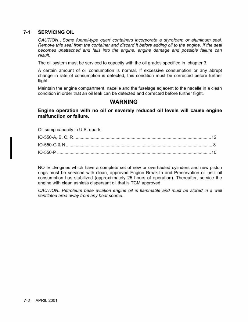
7-2
7-1 SERVICING OILCAUTION…Some funnel-type quart containers incorporate a styrofoam or aluminum seal.Remove this seal from the container and discard it before adding oil to the engine. If the sealbecomes unattached and falls into the engine, engine damage and possible failure canresult.
The oil system must be serviced to capacity with the oil grades specified in chapter 3.A certain amount of oil consumption is normal. If excessive consumption or any abruptchange in rate of consumption is detected, this condition must be corrected before furtherflight.Maintain the engine compartment, nacelle and the fuselage adjacent to the nacelle in a cleancondition in order that an oil leak can be detected and corrected before further flight.
WARNINGEngine operation with no oil or severely reduced oil levels will cause enginemalfunction or failure.
Oil sump capacity in U.S. quarts:IO-550-A, B, C, R...............................................................................................................12IO-550-G & N ...................................................................................................................... 8IO-550-P ............................................................................................................................10
NOTE...Engines which have a complete set of new or overhauled cylinders and new pistonrings must be serviced with clean, approved Engine Break-In and Preservation oil until oilconsumption has stabilized (approxi-mately 25 hours of operation). Thereafter, service theengine with clean ashless dispersant oil that is TCM approved.CAUTION...Petroleum base aviation engine oil is flammable and must be stored in a wellventilated area away from any heat source.
APRIL 2001

7-3
FIGURE 7-1. IO-550-A, B, C OIL SERVICING POINTS
APRIL 2001

7-4
OilFilter
OilCooler
Oil SumpDrains
Oil PressureConnection
Oil Filler & Dipstick
OilTemperatureConnection
OilCooler
FIGURE 7-2. IO-550-G, N OIL SERVICING POINTS
APRIL 2001

7-5
Oil SumpDrain
Oil PressureConnection
OilCooler
Oil Filter
Oil Filler & Dipstick
OilTemperatureConnection
OilCooler
Oil SumpDrain
FIGURE 7-3. IO-550-P OIL SERVICING POINTS
APRIL 2001

7-6
IO-550-R
OilFilter
OilCooler
Oil SumpDrain
Oil PressureConnection
Oil SumpDrain
Oil Filler & Dipstick
OilTemperatureConnection
OilCooler
FIGURE 7-4. IO-550-R OIL SERVICING POINTS
APRIL 2001
7-7
7-2 OIL FILTER ELEMENT INSPECTIONOil filter element inspection is recommended at each oil and filter change even if oil analysisis being used. Filter element inspection may identify internal engine wear that will not beidentified through oil analysis.New, rebuilt, overhauled engines or engines that have had cylinders replaced will generallyexhibit noticeable amounts of normal wear material at the first and second oil and filterchange. The amount of material present should significantly decrease between the first andsecond oil and filter change if the engine and or cylinders have been properly operatedduring the break-in period.As with oil analysis, oil filter element inspection provides maintenance personnel withadditional information on the wear characteristics of a specific engine. Sudden, unexplainedincreases in concentration of wear material in a filter element should alert maintenancepersonnel to investigate the source and cause of the material.Material Identification:Ferrous—attracts to magnet.Aluminum—will "sizz" or bubble when placed in a 50 % solution of muriatic acid.Bronze or Copper—will turn bright green when placed in nitric acid.Carbon—will disintegrate when rubbed between index finger and thumb.Sand—will not disintegrate when rubbed between two hard surfaces and will scratch glasswhen pressure is applied.Nickel—will not be magnetically attracted but looks similar to ferrous material.Tin—will not be attracted magnetically. It looks similar to nickel but is soft and malleable.
7-3 SPECTROGRAPHIC OIL ANALYSISSpectrographic oil analysis has become popular with the owners and operators of generalaviation piston powered aircraft. This process was developed more than 35 years ago by therailroads as a method of identifying wear characteristics in large diesel engines. Eventuallyoil analysis was adopted by the military and then by commercial and general aviation.Engines are designed and manufactured using various materials and alloys. The enginelubrication system is designed to provide either pressure or splash oil to areas of the enginesubjected to frictional loading. During normal operation these areas undergo minute,continuous wear; sub microscopic material is released from these contact surfaces and aresuspended in the lubricating oil. Spectrographic oil analysis identifies these materials andtheir level of concentration in parts per million (PPM).There are two accepted methods of performing oil analysis: atomic absorption and atomicemissions.Atomic absorption will identify suspended wear material that is five micron in size or smaller,while atomic emissions will identify suspended wear material that is ten micron in size orsmaller. Since engine oil analysis is used as a tool to establish engine wear trends anddeviations from the established norm, either method is acceptable; however, it is important torealize the oil analysis program must utilize the same laboratory for all sample analysis.Comparing an oil analysis report from a separate laboratory will have little meaning if eachlaboratory uses a different analysis method.
APRIL 2001

7-8
A proper spectrographic oil analysis program should begin with the first engine oil change.Establishing a wear trend data base for an engine will require analysis of at least three oilsamples. As the engine accumulates operating time and additional oil samples are analyzed,a definitive wear trend can be identified. Unexplained deviations from normal wear trendpatterns should be investigated using accepted, conventional inspection methods.Spectrographic oil analysis must be accomplished according to a set protocol to provide anyuseful information. Even if done properly, spectrographic oil analysis will rarely provide anyprior indication of a fatigue type failure. A single spectrographic oil sample will usually notprovide a high level of useful information since there is no established wear breed data onthat specific engine for comparison.Spectrographic oil analysis will assist in the identification of an internal engine problem. Ifsamples are properly taken at regular intervals, it should provide the owner / operator and oilanalysis technician with information relative to normal or abnormal wear that occurs duringthe course of engine operation. Deviations from an established wear trend pattern shouldalert the owner / operator and oil analysis technician to further investigate.LimitationsVariations in operation, use and maintenance may be reflected in the parts per millioncontent reported. Deviations from standard or previously used sampling procedures mayresult in variations to the parts per million content in the sample report.General ProceduresTo establish a data base for comparison and analysis, oil samples must be taken on aregular schedule using the same sampling techniques and laboratory. The engine must havebeen operated long enough to obtain normal operational temperatures and the oil sampletaken within 30 minutes after engine shut down. The tube or funnels used to drain the oilfrom the sump must be clean and free of any debris or residue. If the oil sample is taken fromthe oil as it drains from the sump, allow approximately 1/3 of the oil drain prior to taking thesample. If the sample is taken via the oil filler or other location using a sampling tube, it iscritical the sample be taken from two or three inches above the bottom of the oil sump, notfrom the bottom. Do not take an oil sample from the oil filter canister.
APRIL 1998
7-9
7-4 SERVICING FUELAviation Min. Grade .................................................................. 100LL (Blue) or 100(Green)See the applicable airframe manufacturer’s instructions for aircraft Fueling Procedure andFueling Points.
WARNINGThe use of lower octane rated fuel or jet fuel will result in damage ordestruction of an engine the first time high power is applied. This would mostlikely occur on takeoff. If the aircraft is inadvertently serviced with the wronggrade of fuel or jet fuel the fuel must be completely drained and the tankproperly serviced.Any engine operated on fuel of lower grade than approved for the engine or jet fuel must becompletely disassembled, cleaned, inspected, repaired, reassembled and tested in accordancewith the current overhaul manual.
APRIL 1998

7-10
INTENTIONALLY
LEFT
BLANK

8-1
CHAPTER 8
Engine Preservation and Storage
Engine engine preservation and storage must be performed in accordance with the instructions inthe I0-550-A,B,C,G,N,P and R Operation and Installation Manual, Form X30565.
APRIL 2001

8-2
INTENTIONALLY
LEFT
BLANK

9-1
CHAPTER 9
STANDARD PRACTICES
SECTION PAGE9-1 General .............................................................................................9-29-2 Lockwire Procedure..........................................................................9-39-3 Tab Washer Procedure ....................................................................9-59-4 Cotter Pin Procedure ........................................................................9-59-5 Application Of Adhesives..................................................................9-69-6 Installation Of Gaskets......................................................................9-69-7 Hose And Tubing Installation........................................................ 9-6
FIGURE PAGE9-1 General Lockwire Procedure............................................................9-39-2 General Lockwire Patterns ...............................................................9-49-3 Tab Washer Installation Procedure..................................................9-59-4 General Cotter Pin Installation Procedure........................................9-69-5 Torquing Hose Fittings .....................................................................9-79-6 Torquing Hose Fittings .....................................................................9-7
APRIL 2001

9-2
9-1 GENERAL
To facilitate and insure proper reinstallation, tag or mark all parts and hardware as they areremoved or disassembled.
Tag any unserviceable parts or units for investigation and possible repair. Take extreme care toprevent lockwire, nuts, washers, dirt, etc., from entering the engine on or off the aircraft. Makeuse of protective caps, plugs and covers to insure openings are unexposed.
CAUTION…Dust caps used to protect open lines must be installed OVER the tube ends andNOT IN the tube ends. Flow through the lines will be blocked if lines are inadvertently installedwith the dust caps in the tube ends.
If anything is dropped into the engine work must be stopped immediately and the itemremoved.
Insure all parts are thoroughly clean and lubricated as specified before assembling.
All lockwire and cotter pins must fit snugly in holes drilled in specific hardware. On castellatednuts, unless otherwise specified, the cotter pin head must fit into a recess of the nut with theother end bent such that one leg is back over the stud and the other is down flat against the nutin accordance with Section 9-4. Use only manufacturer specified corrosion resistant steel cotterpins. All lockwire utilized on TCM engines must conform to MS20995 Condition A.
When replacing gaskets, packings, or rubber parts use the type or composition specified by themanufacturer.Make sure replacement nonmetallic and metallic parts show no sign of storage deterioration.Parts exceeding specified shelf life limitations must not be used.
When a hammer is required to come in direct contact with an engine part during assembly ordisassembly, use a mallet made of plastic or rawhide material only.
Parts removed from the engine must be cleaned and inspected in accordance with thespecified instructions located in the applicable system chapter.
APRIL 1998

9-3
9-2 LOCKWIRE PROCEDURE
Lockwiring is the securing together of two or more parts with lockwire installed in such amanner that any tendency for a part to loosen will be counteracted by additional tightening ofthe lockwire.
All lockwire utilized on TCM engines must conform to MS20995 Condition A. Most bolts utilizedin TCM engines that require lockwiring will use .032 lockwire and require twisting at a rate of 7to 10 twists per inch. Smaller lockwire (when specified or required) will require twisting at a rateof 9 to 12 twists per inch. Lockwire must be new at each application.
Lockwire must be pulled taut while being twisted and caution must be exercised during thetwisting operation to keep the lockwire tight without overstressing. See Figure 9-1, "GeneralLockwire Procedure," for steps in applying lockwire.
FIGURE 9-1. GENERAL LOCKWIRE PROCEDURE

9-4
Various examples of lockwiring are shown in Figure 9-2, "General Lockwire Patterns."
1. Check the units to be lockwired to insure they have been correctly torqued. Applying torquethat is above or below specified limits to obtain alignment of the holes is not permitted.
2. It is desirable to have the holes parallel, but this is not a necessity. For right hand threads, the
lockwire shall be installed in such a manner that the strand through the hole will have atendency to pull the unit clockwise.
3. Insert half of the required lengh of lockwire through the first unit and bend around the head of
the unit. The direction of wraps and twist of strands shall be such that the loop around the unitcomes under the strand protruding from the hole so that the loop will stay down and will nottend to slip up and leave a slack loop.
4. Twist the strands while taut until the twisted part is just short of a hole in the next unit. Thetwisted portion should be within one-eighth (1/8) inch from the hole in either unit.
5. Insert the uppermost strand through the hole in the second unit and follow the rules inParagraph three.
1. After lockwiring the last unit continue twisting the lockwire to form a pigtail, providing sufficient
twists (four minimum) to assure that the pigtail will not unravel. Cut off the excess lockwire andbend the pigtail toward the part and against the bolt head flats. DO NOT ALLOW THE PIGTAILTO EXTEND ABOVE THE BOLT HEAD.
FIGURE 9-2. GENERAL LOCKWIRE PATTERNS
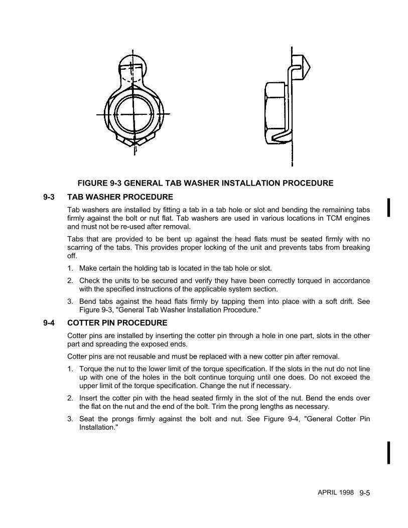
9-5
9-3 TAB WASHER PROCEDURETab washers are installed by fitting a tab in a tab hole or slot and bending the remaining tabsfirmly against the bolt or nut flat. Tab washers are used in various locations in TCM enginesand must not be re-used after removal.Tabs that are provided to be bent up against the head flats must be seated firmly with noscarring of the tabs. This provides proper locking of the unit and prevents tabs from breakingoff.1. Make certain the holding tab is located in the tab hole or slot.2. Check the units to be secured and verify they have been correctly torqued in accordance
with the specified instructions of the applicable system section.3. Bend tabs against the head flats firmly by tapping them into place with a soft drift. See
Figure 9-3, "General Tab Washer Installation Procedure."
9-4 COTTER PIN PROCEDURECotter pins are installed by inserting the cotter pin through a hole in one part, slots in the otherpart and spreading the exposed ends.Cotter pins are not reusable and must be replaced with a new cotter pin after removal.1. Torque the nut to the lower limit of the torque specification. If the slots in the nut do not line
up with one of the holes in the bolt continue torquing until one does. Do not exceed theupper limit of the torque specification. Change the nut if necessary.
2. Insert the cotter pin with the head seated firmly in the slot of the nut. Bend the ends overthe flat on the nut and the end of the bolt. Trim the prong lengths as necessary.
3. Seat the prongs firmly against the bolt and nut. See Figure 9-4, "General Cotter PinInstallation."
FIGURE 9-3 GENERAL TAB WASHER INSTALLATION PROCEDURE
APRIL 1998

9-6
9-5 APPLICATION OF ADHESIVESAdhesives and sealants will be used only in specific applications outlined in Chapter 3, "TableOf Sealants and Lubricants."
WARNINGThe improper use of sealants and lubricants may cause engine malfunction orfailure.Gasket Maker P/N 646942 - Surfaces must be clean and free of nicks, burrs, oil and grit. Applya thin translucent coat of Gasket Maker not to exceed .010 inch thick to the surface specified inChapter 3, "Table Of Sealants Sealants and Lubricants."Gasket Maker is an easily workable tacky gel which can be extruded onto one side of a flangesurface from a tube and evenly spread. Small parts can be covered adequately by pressingthem into a saturated polyester urethane sponge or by roll coating them with a short nap roller.Once Gasket Maker has been applied evenly torque assembly into place. Excess material canbe cleaned by wiping with chlorinated solvent. Material on hands can be cleaned with waterlessmechanics hand soap followed by soap and water.
NOTE…TCM general purpose primer P/N 653160 must be used for surface preparationbefore applying Gasket Maker at the engine nose seal area.
9-6 INSTALLATION OF GASKETSAll gaskets must be new, of the proper material and visually inspected prior to installation.Following visual inspection, if the gasket shows any indication of gouges, nicks, cuts or bendand fatigue marks replace with a new manufacturer specified gasket.Gasket surfaces must be clean and free of nicks, burrs, oil and grit. Apply a thin coat of TCMGasket Sealant P/N #642188-1 to both sides of gasket unless otherwise specified. SeeChapter 3, "Table Of Sealants and Lubricants," for application of gasket sealant. Once TCMGasket Sealant has been applied install gasket. Install assembly and evenly torque hardwareto specified value. This will prevent over stressing gasket.
WARNINGGaskets and components must be properly positioned, hardware torqued andsafetied as required during assembly to prevent oil loss.
9-7 HOSE AND TUBING INSTALLATIONIt is required that the following procedure be used when hoses and tubing are removed,attached and torqued to fittings contained on components such as fuel, induction, lubricationand turbocharger systems.
FIGURE 9-4. GENERAL COTTER PIN INSTALLATION
APRIL 2001

9-7
WARNINGFailure to properly support component fittings can result in fitting and/orcomponent damage and a resulting loss of system pressure.1. See Figures 9-5 and 9-6.2. Select the proper size open end wrenches that will fit the fitting body and hose or tubing
end fitting.3. Torque or loosen (as required) the hose or tubing end fitting while maintaining sufficient
force on the component fitting to prevent twisting and shear loads.4. Components that contain multiple fittings coupled in one location must have the last fitting
in the assembly properly supported as indicated in the preceding paragraphs.5. DO NOT over torque fittings. Consult the appropriate manufacturer's manual for specific
installation procedures and torque values.
APRIL 2001

9-8
INTENTIONALLY
LEFT
BLANK
10-1
CHAPTER 10
ENGINE MAINTENANCE
10-1 GENERALDuring engine 50 and 100 hour inspections, if engine components must be removed andreplaced, refer to the applicable disassembly/reassembly instructions found in the IO-550Permold Series Overhaul Manual, Form X30568A as outlined in Maintenance Section ofeach system.NOTE...Engine operational inspection must be performed prior to any 50 or 100 hour staticinspections. See Chapter 5 "Operational Inspecton."Corrections and adjustments will be found in the individual system chapters of this manualunder "Maintenance," and Chapter 22, "Post Maintenance Adjustment And Test."At the completion of all 50/100 hour inspection procedures, see Chapter 22 and perform thepost maintenance operational test.
APRIL 1998

10-2
INTENTIONALLY
LEFT
BLANK
11-1
CHAPTER 11
EXHAUST SYSTEM
11-1 EXHAUST SYSTEMThis chapter is reserved for engines utilizing an exhaust system and components supplied onsome engine models by Teledyne Continental Motors. For I0-550-A, B, C, G, N, P & Rexhaust system maintenance, see the airframe manufacturer's instructions.
APRIL 2001

11-2
INTENTIONALLY
LEFT
BLANK
12-1
CHAPTER 12
IGNITION SYSTEM
SECTION PAGE12-1 TCM Ignition System Description ...............................................12-212-2 Slick Ignition System Description ...............................................12-312-3 Ignition System Component Detailed Description......................12-312-4 Spark Plugs.................................................................................12-412-5 Magneto to Engine Timing..........................................................12-512-6 Ignition System Maintenance .....................................................12-10
FIGURE PAGE12-1 Spark Plug Rotation....................................................................12-412-2 Spark Plug Wear.........................................................................12-512-3 Timing Position Step 1................................................................12-712-4 Timing Position Step 2................................................................12-812-5 Timing Position Step 3................................................................12-812-6 Timing Position Step 4................................................................12-912-7 Timing Position Step 5................................................................12-912-8 Service Limits..............................................................................12-1012-9 Ignition Wiring Diagram ..............................................................12-11
APRIL 2001

12-2
12-1 TCM IGNITION SYSTEM DESCRIPTIONDual ignition is provided by two magnetos. The left magneto fires 1-3-5 lower and 2-4-6 upperspark plugs, while the right magneto fires the 1-3-5 upper and 2-4-6 lower spark plugs.The TCM S6RN-201, -205, 1201, 1205 series magnetos are designed to provide ignition for sixcylinder aircraft engines. The magnetos generate and distribute high tension current throughhigh tension leads to the spark plugs. Because of the one piece housing design, these hightension magnetos are comparatively easy to maintain between overhauls. The magnetos mustbe overhauled at engine overhaul or four calendar year interval in accordance with theapplicable Magneto Service Manual.To obtain the retard spark necessary for starting, the S-20 series magnetos and some S-1200series magnetos employ an impulse coupling. The purpose of the impulse coupling is to: (1)rotate the magneto between impulse trips faster than the engine cranking speed thusgenerating a better spark for starting the engine, (2) automatically retard the spark duringengine cranking, and (3) act as a drive coupling for the magneto. S-200 series magnetos andsome S-1200 series magnetos employ the "shower of sparks" ignition system, including astarter vibrator. The purpose of the "shower of sparks" is to: (1) boost ignition energy by feedingpulsating battery voltage to the magneto primary circuit during starting and (2) automaticallyretard the spark during engine cranking.The following detailed explanation gives the meaning of the various letters and numbersappearing in the type designations:
S 6 R N - 1201
Magneto ConfigurationS = Single Type Magneto:
one drive, one output distributorD = Dual Type Magneto:
one drive, two output distributors
Cylinders Fired4 = Four Cylinders6 = Six Cylinders8 = Eight Cylinders
Rotatlon As ViewedLooking At Drive End
L = Left (counterclockwise)R = Right (clockwise)
DesignatorN = Scintilla DesignSC = Short Cover
Model NumberS-20 Serles20: Dog-Ear Mount, No Impulse Coupling21: Dog-Ear Mount, Impulse Coupled23: Dog-Ear Mount, Impulse Coupled, MilitaryShielding25: Deep Flange Mount, Impulse Coupled25P:Deep Flange Mount, Impulse Coupled,PressurizedS-200 Serles200: Dog Ear Mount, With Retard Breaker201: Deep Flange Mount, With Retard Breaker204: Dog Ear Mount, Without Retard Breaker205: Deep Flange Mount, Without Retard BreakerS-1200 Serles1201: Deep Flange Mount, With Retard Breaker1205: Deep Flange Mount, Without Retard Breaker1208: Short Flange Mount, With Retard Breaker1209: Short Flange Mount, Without Retard Breaker1225: Deep Flange Mount, lrnpulse Couple1227: Short Flange Mount, Impulse Coupled1251: Pressurized Version of 12011255: Pressurized Version of 12051258: Pressurized Version of 12081259: Pressurized Version of 1209D-3000 Serles3000: Impulse Coupled3200: With Retard Breaker

12-3
The following detailed explanation gives the meaning of the various letters and numbers appearing inthe TCM magneto serial number (Manufacturing Number). Example: B138901FR
B 13 89 01 F R
Month
A. JanuaryB. FebruaryC. MarchD. AprilE. MayF. JuneG. JulyH. AugustI. SeptemberJ. OctoberK. NovemberL. December
Day ofMonth
Year(1989)
SequentialNumber for unit
begins with"01" each day
ProductCode:
D: S-20E: S200F: S1200G: D3000
FactoryRebuilt
(No letterfor new)
12-2 SLICK IGNITION SYSTEM COMPONENT DETAILED DESCRIPTIONConventional dual ignition is provided by two magnetos. The left magneto fires the 1-3-5- lowerand the 2-4-6 upper spark plugs, while the right magneto fires the 1-3-5 upper and 2-4-6 lowerspark plugs.The Slick 6210 Series Magnetos, manufactured by Unison Industries, 530 Blackhawk ParkAvenue, Rockford, Illinois 61101, are designed to provide ignition for six cylinder light aircraftengines. The magnetos generate and distribute high tension current through high tension leadsto the spark plugs.To obtain the retard spark necessary for starting, the magnetos employ an impulse coupling.The purpose of the impulse coupling is to: (1) rotate the magneto between impulse trips fasterthan engine cranking speed, thus generating a better spark for starting the engine; (2)automatically retard the spark during engine cranking, and (3) act as a drive coupling for themagneto.The following detailed explanation gives the meaning of the various numbers appearing in theSlick serial number.
EG-2 03 132
12-3 IGNITION SYSTEM COMPONENT DETAILED DESCRIPTIONFor a detailed description of magnetos and harnesses see TCM Ignition System MasterService Manual Form X40000 or Slick Ignition Systems Master Service Manual Form F-1100as applicable. See Related Publications section 1-5 for ordering information.Magneto Accessory Drive Adapter - Each magneto is driven by a magneto drive shaft,retainer and bushings housed inside a magneto and accessory drive adapter. The adapters areattached to the upper rear portion of the crankcase and secured by four studs, washers andnuts. The magneto drive shafts are installed in the front of the adapter and meshed in theproper position with the idler gear. Two rubber bushings (per magneto) are installed within a
The year of manufacture(2=1982)
The month of manufacture(03=March)
The number of aparticular modelmanufactured in themonth specified
APRIL 2001

12-4
retainer on the drive shaft. The rubber bushings provide a shock absorbing engagementbetween magneto and engine drive train.
12-4 Spark PlugsRemove spark plugs for cleaning or replacement in accordance with the applicabledisassembly/reassembly instructions in the IO-550-A,B,C,G, N, P & R Overhaul Manual, FormX30568A.After spark plugs are removed:1. Clean and gap or replace in accordance with the spark plug manufacturer’s specifications.2. Test spark firing under pressure using a Champion® cleaner/tester or equivalent.3. Replace any spark plug that does not fire properly. Insure that each spark plug is free ofresidue from the cleaning process.4. Apply Champion® thread lubricant to all spark plugs in accordance with themanufacturer’s instructions and reinstall spark plugs in the reverse spark plug installationorder. Do not torque spark plugs at this time.
CAUTION...Never install a spark plug that has been dropped, discard it.
Use Figure 12-2 to help you make an informed decision whether to clean, regap, and reuse aspark plug or discard it.
135
246
T B T B T B
T BT BT B
C YLIN D ERN U M B ER
C YLIN D ERN U M B ER
FR O M TO
1 TO P 6 B O TTO M
1 B O TTO M 6 TO P
C YLIN D ER R O TA TIO N
2 TO P 5 B O TTO M
2 B O TTO M 5 TO P
3 TO P 4 B O TTO M
3 B O TTO M 4 TO P
4 TO P 3 B O TTO M
4 B O TTO M 3 TO P
5 TO P 2 B O TTO M
5 B O TTO M 2 TO P
6 TO P 1 B O TTO M
6 B O TTO M 1 TO P
FIGURE 12-1. SPARK PLUG ROTATION
APRIL 2001

12-5
12-5 Magneto to Engine Timing
WARNINGTo prevent possibility of serious bodily injury or death, before moving thepropeller accomplish the following:
a. Disconnect all spark plug leads.b. Verify magneto switches are connected to magnetos, that they are in
the "OFF" Position and "P" leads are grounded.c. Throttle position "CLOSED."d. Mixture control "IDLE-CUT-OFF."e. Set brakes and block aircraft wheels. Insure that aircraft tie-downs are
installed and verify that the cabin door latch is open.f. Do not stand within the arc of the propeller blades while turning the
propeller.
NORMAL ELECTRODE CONDITIONInsulator tip gray, tan or light brown. Few combustiondeposits. Electrodes not burned or eroded. Propertype heat range plug for engine and service. Sparkplug should be cleaned regapped and tested beforereinstallation.
NORMAL WORN-OUT CONDITIONElectrodes eroded by high-voltage sparking and bycorrosive gases formed during combustion to lessthan 1/2 original thickness. More voltage needed tofire spark plugs - often more than ignition system canproduce. Discard and replace with new spark plugs.
SEVERE WORN-OUT CONDITIONExcessively eroded center and ground electrodesplus extensive necking of fine wire ground electrodesindicate abnormal engine power or plugs long over-due for replacement. Check fuel metering and magnetotiming. Discard spark plugs and check heat rangebefore installing new ones.
ELECTRODE WEAR PATTERNSConstant polarity occurs with even-numbered cylindermagnetos. One plugs fires with positive polarity, causingexcessive ground-electrode wear, while the next plug firesnegatively, causing excessive center electrode wear. Toequalize this, rotate as indicated in Figure 12-1.
FIGURE 12-2. SPARK PLUG WEAR
APRIL 2001

12-6
WARNINGMagneto-to-engine timing does not insure magneto, harness, and spark plugperformance. Failure to properly maintain the magneto, harness, and sparkplugs may lead to internal engine damage and failure. Magneto, ignition harness,and spark plugs must be maintained in accordance with the manufacturer’sinstructions.CAUTION...A single severe kickback while cranking the engine can cause failure ofcomponents in the cranking system. Kickback can be caused by intermittent operation of theimpulse couplings. Perform the following operational test at the specified intervals to insure thatthese systems are functioning properly.
Magneto Impulse Coupling Test
WARNINGFailure to properly ground magnetos may result in engine ignition and possibleinjury to personnel.1. Insure that both magnetos are properly grounded and that all spark plugs are installed in all
cylinders. Remove all spark plug harness lead ends from the spark plugs and ground themto the engine to prevent ignition.
2. Before cranking engine perform the following:a. Magneto switch, if separate from starter switch .........................................................OFFb. Mixture ..................................................................................................... IDLE CUT OFFc. Throttle ...............................................................................................................CLOSEDd. Fuel selector ...............................................................................................................OFFe. Master switch .................................................................................................... ON
3. Crank engine several revolutions.
WARNINGUse extreme caution in the area of the propeller while performing this test. Donot stand or allow anyone else to stand in the propeller arc area.
a. Impulse coupling operation is audible and can be felt through the magneto housings.The impulse couplings should consistently click together while the engine is beingcranked.
b. If no clicking or if only intermittent clicking is heard, remove the magnetos and servicethem in accordance with the magneto manufacturer's instructions.
APRIL 1998

12-7
When performing a magneto timing check, use the following tools:
• Top dead center locator• Protractor and Pointer The Eastern Electronics Model E25 Timing Indicator kit or equivalent is recommended.Use the following timing procedure to insure correct engine timing.
NOTE...Whenever setting or checking timing, always turn the crankshaft steadily in the direction ofrotation to eliminate backlash error.
Timing Steps
1. Remove all top spark plugs. Rotate the crankshaft in the direction of normal rotation untilthe number one piston is at top dead center on the compression stroke. Rotate thecrankshaft in the opposite direction of normal rotation until the piston is far enough downthe barrel to allow the TDC locator to be installed.
2. Install the top dead center locator into No. 1 cylinder top spark plug hole.3. Install timing disc of indicator being used on the crankshaft flange.4. Turn crankshaft slowly in direction of normal rotation until piston lightly touches TDC
locator.5. Rotate disc of timing indicator until the 0 degree mark aligns with the pointer.6. Slowly turn crankshaft in opposite direction of normal rotation until the piston lightly
touches TDC locator.
FIGURE 12-3. TIMING PROCEDURE STEP 1
APRIL 2001
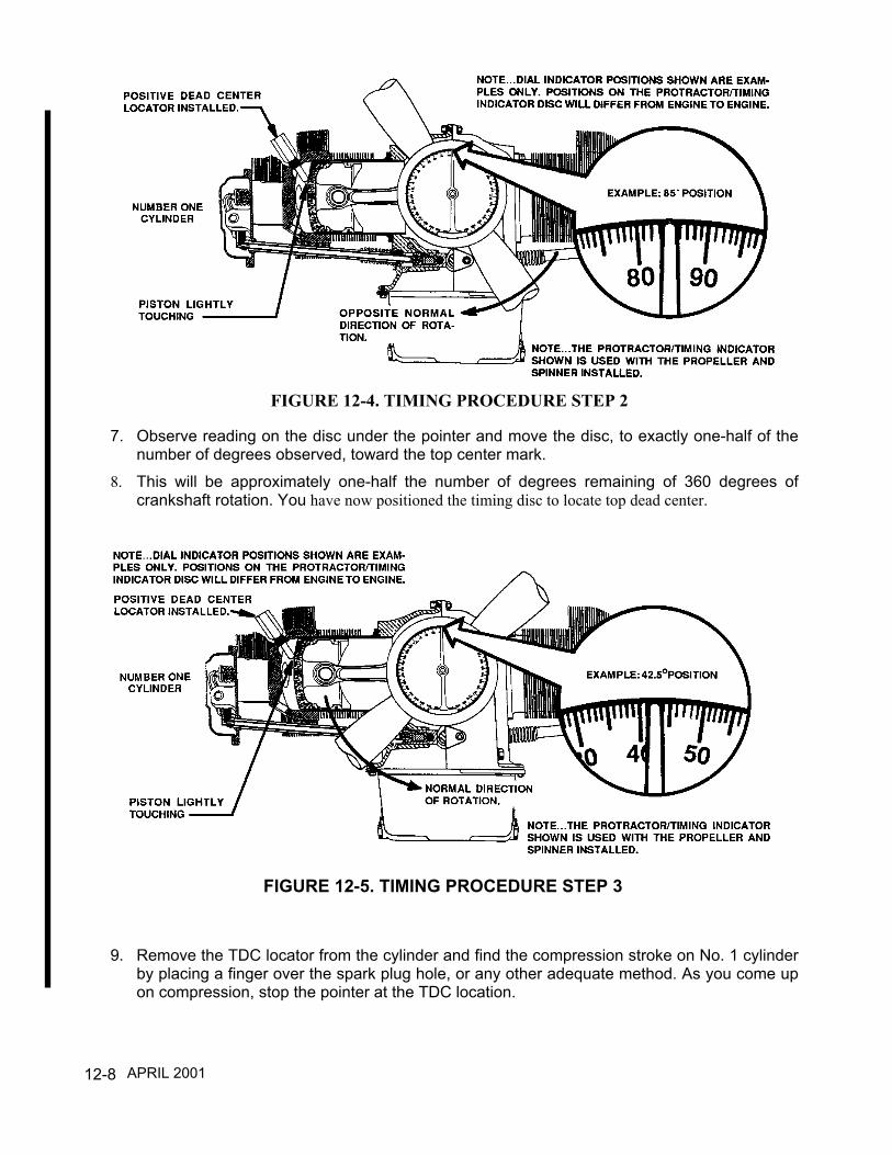
12-8
7. Observe reading on the disc under the pointer and move the disc, to exactly one-half of thenumber of degrees observed, toward the top center mark.
8. This will be approximately one-half the number of degrees remaining of 360 degrees ofcrankshaft rotation. You have now positioned the timing disc to locate top dead center.
9. Remove the TDC locator from the cylinder and find the compression stroke on No. 1 cylinderby placing a finger over the spark plug hole, or any other adequate method. As you come upon compression, stop the pointer at the TDC location.
FIGURE 12-4. TIMING PROCEDURE STEP 2
FIGURE 12-5. TIMING PROCEDURE STEP 3
APRIL 2001
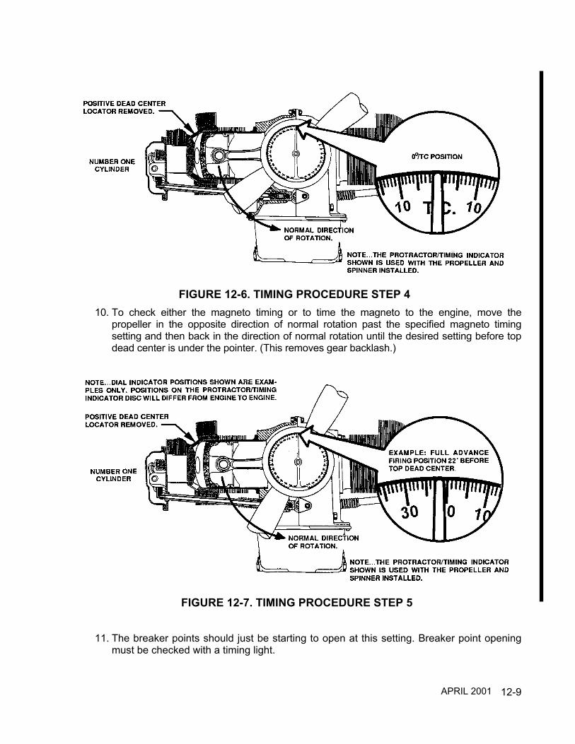
12-9
10. To check either the magneto timing or to time the magneto to the engine, move thepropeller in the opposite direction of normal rotation past the specified magneto timingsetting and then back in the direction of normal rotation until the desired setting before topdead center is under the pointer. (This removes gear backlash.)
11. The breaker points should just be starting to open at this setting. Breaker point openingmust be checked with a timing light.
FIGURE 12-6. TIMING PROCEDURE STEP 4
FIGURE 12-7. TIMING PROCEDURE STEP 5
APRIL 2001
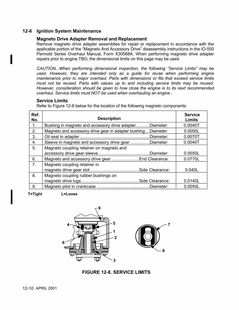
12-10
12-6 Ignition System MaintenanceMagneto Drive Adapter Removal and ReplacementRemove magneto drive adapter assemblies for repair or replacement in accordance with theapplicable portion of the “Magneto And Accessory Drive” disassembly instructions in the IO-550Permold Series Overhaul Manual, Form X30568A. When performing magneto drive adapterrepairs prior to engine TBO, the dimensional limits on this page may be used.
CAUTION...When performing dimensional inspection, the following “Service Limits” may beused. However, they are intended only as a guide for reuse when performing enginemaintenance prior to major overhaul. Parts with dimensions or fits that exceed service limitsmust not be reused. Parts with values up to and including service limits may be reused.However, consideration should be given to how close the engine is to its next recommendedoverhaul. Service limits must NOT be used when overhauling an engine .
Service LimitsRefer to Figure 12-8 below for the location of the following magneto components:
Ref.No. Description
ServiceLimits
1. Bushing in magneto and accessory drive adapter............Diameter: 0.0040T2. Magneto and accessory drive gear in adapter bushing....Diameter: 0.0050L3. Oil seal in adapter ..........................................................Diameter: 0.0070T4. Sleeve in magneto and accessory drive gear ................Diameter: 0.0040T5. Magneto coupling retainer on magneto and
accessory drive gear sleeve...........................................Diameter: 0.0550L6. Magneto and accessory drive gear .......................End Clearance: 0.0770L7. Magneto coupling retainer in
magneto drive gear slot.........................................Side Clearance: 0.040L8. Magneto coupling rubber bushings on
magneto drive lugs ................................................Side Clearance: 0.0140L9. Magneto pilot in crankcase ............................................Diameter: 0.0050L
T=Tight L=Loose
8
7
���������������������������������������������������������������������������������������������������������������������������������������������������������������������������������������������������������������������������������������������������������������������������������������������������������������������������������������������������������������
������������������������������������������������������������������������������������������������������������������������������������������������������������������������������������������������������������������������������������������������������������
������������������������������������������������������������������������������������������������������������������������������������������������������������������������������������������������������������������������������������������������������������������������������������������������������������������������������������������������������������������������������������������
������������������������������������������������������������������������������������������������������������������������������������������������������������������������������������������������������������������������������������������������������������
4 ����������������������������������������������������������������������������������������������������������������������������������������������������������������������������������������������������������������������������������������������������������������������������������������
��������������������������������������������������
��������������������������������������������������������
������������������������������������������������������������������������������������������������������������������������������������������������������������������������������������������������������������������������������������������������������������
��������������������������������������������������������������������������������������������������������������������������������������������������������������������������������������������������������������������������������������������������������������������������������������������������������������������
9
5
12
3
6
�������������������������������������������������
FIGURE 12-8. SERVICE LIMITS
APRIL 2001

12-11
Magneto Removal and ReplacementRemove the magnetos for repair or replacement in accordance with “Ignition SystemDisassembly/Reassembly” in the IO-550 Permold Series Overhaul Manual, Form X30568A.Magneto maintenance such as point replacement, condenser replacement, impulse couplingreplacement or internal magneto timing must be performed in accordance with the magnetomanufacturer's instructions.
Ignition Harness Removal and ReplacementRemove the harness assemblies for repair or replacement in accordance with the applicable“Ignition System Disassembly/Reassembly instructions” in the IO-550 Permold SeriesOverhaul Manual, Form X30568A.Any harness assembly maintenance such as single lead replacement must be performed inaccordance with the harness manufacturer’s instructions.
2 4
51
3
624
5 1
3
6
RIGHT MAG LEFT MAG
MAGNETO FIRING ORDERENGINE FIRING ORDER 1 6 3 2 5 4
1 2 3 4 5 6
1
3
5
5
3
1
6
4
2
6
2
4
UPPERSPARK PLUGS
UPPERSPARK PLUGS
FIGURE 12-9. IGNITION WIRING DIAGRAM
APRIL 1998

12-12
INTENTIONALLY
LEFT
BLANK
13-1
CHAPTER 13
FUEL SYSTEM
SECTION PAGE13-1 Engine Fuel System Description ..................................... 13-213-2A Altitude Compensating Fuel Pump I0-550-A, B, C.......... 13-413-2B Standard Fuel Pump I0-550-A, B, C................................ 13-613-3 Fuel Pump I0-550-G, N, P, R .......................................... 13-813-4 Throttle and Fuel Control Unit I0-550-A, B, C ................. 13-1013-5 Throttle and Fuel Metering Unit I0-550-G, N, P, R.......... 13-1113-6 Fuel Control Unit I0-550-A, B, C...................................... 13-1213-7 Fuel Metering Unit I0-550-G, N, P, R .............................. 13-1313-8 Fuel Manifold Valve ......................................................... 13-1313-9 Fuel Nozzle...................................................................... 13-1413-10 Fuel System Maintenance............................................... 13-15
FIGURE PAGE13-1 Fuel System Schematic IO-550-A, B, C.......................... 13-213-2 Fuel System Schematic IO-550-G, N, P, R..................... 13-313-3A Altitude Compensating Fuel Pump
Description IO-550-A, B, C.............................................. 13-513-3B Standard Fuel Pump Description IO-550-A, B, C ........... 13-713-4 Fuel Pump Description IO-550-G, N, P, R ...................... 13-913-5 Air Throttle & Fuel Control General
Description IO-550-A, B, C.............................................. 13-1013-6 Throttle And Fuel Metering Unit
Description IO-550-G, N, P, R......................................... 13-1113-7 Fuel Control Unit General Description
IO-550-A, B, C ................................................................. 13-1213-8 Fuel Metering Unit Description IO-550-G, N, P, R .......... 13-1313-9 Fuel Manifold Valve General Description........................ 13-1313-10 Fuel Nozzle General Description..................................... 13-1413-11 Throttle and Fuel Control Unit
Lubrication IO-550-A, B, C .............................................. 13-1713-12 Throttle and Fuel Control Unit
Lubrication IO-550-G, N, P, R ......................................... 13-1713-13 Fuel Pump Drive Fits and Limits ..................................... 13-2013-14A General F / I Sealant Application..................................... 13-2513-14B General Fuel Nozzle Anti-Seize Application................. 13-25
TABLE PAGE1 Torque Specifications For Fittings................................... 13-262 Torque Specifications For Hose Fittings ......................... 13-26
APRIL 2001
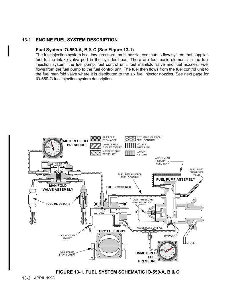
13-2
13-1 ENGINE FUEL SYSTEM DESCRIPTION
Fuel System IO-550-A, B & C (See Figure 13-1)The fuel injection system is a low pressure, multi-nozzle, continuous flow system that suppliesfuel to the intake valve port in the cylinder head. There are four basic elements in the fuelinjection system: the fuel pump, fuel control unit, fuel manifold valve and fuel nozzles. Fuelflows from the fuel pump to the fuel control unit. The fuel then flows from the fuel control unit tothe fuel manifold valve where it is distributed to the six fuel injector nozzles. See next page forIO-550-G fuel injection system description.
�������������������������������������������������������������������������������������������������������������������������������������������������������������������������������������������������������������������������������������������������������������������������������������������������������������������������������������������������������������������������������������������������
��������������������������������������������������������������������������������
����������������������������������������������������������������������������������������������������������������������������������������������������������������������������������������������������������������������������������������������������������������������������������������������������������������������������������������������������������������������������������������������������������������������������������������������������������������������������������������������������������������������������������������������������������������������������������������������������������������������������������������������������������������������������������������������������������������������������������������������������������������������������������������������������������������������������������������������������������������������������������������������������� ��������������������������������������������������������������
��������������������������������������������������������������������������������������������������������������������������������������������������������������������������������������������������������������������������������������������������������������������������������������������������������������������������������������������������������������������������������������������������������������������������������������������������������������������������������������������������������������������������������������������������������������������������������������������������������������������������������������������
��������������������������������������������������������������������������������������������������������������������������������������������������������������������������������������������������������������������������������������������������������������������������������������������������������������������������������������������������������������������������������������������������������������������������������������������������������������������������������������������������������������������������������������������������������������������������������������������������������������������������������������������������������������������������������������������������������������������������������������������������������������������������������������������������������������������������������������������������������������������������������������������������������������������������������������������������������������������������������������������������������������������������������������������������������������������������������������������������������������������������������������������������������������������������������������������������������������������������������������������������������������������������������������������������������������������������������������������������������������������������������������������������������������������������������������������������������������������������������������������������������������������������������������������������������������������������������������������������������������������������������������������������������������������������������������������������������������������������������������������������������������������������������������������������������������������������������������������������������������������������������������������������������������������������������������������������������������������������������������������������������������������������������������������������������������������������������������������������������������������������������������������������������������������������������������������������������������������������������������������������������������������������������������������������������������������������������������������������������������������������������������������������������������������������������������������������������������������������������������������������������������������������������������������������������������������������������������������������������������������������������������������������
����������������������������������������������������������������������������������������������������������������������������������������������������������������������������������������������������������������������������������������������������������
��������������������������������������������������������������������������������������������������������������������������������������������������������������������������������������������������������������������������������������������������������������������������������������������������������������������������������������������������������������������������������������������������������������������������������������������������������������������������������������������������������������������������������������������������������������������������������������������������������������������������������������������������������
������
4 68
10
12
141618
20
2
FUELPRESSURE P.S.I.
4 68
10
12
141618
20
2
FUELPRESSURE P.S.I.
METERED FUELPRESSURE
MANIFOLDVALVE ASSEMBLY
UNMETEREDFUEL
PRESSURE
THROTTLE BODY
FUEL CONTROL
FUEL PUMP ASSEMBLY
FUEL INJECTORS
IDLE MIXTUREADJUST
IDLE SPEEDSTOP SCREW
VAPOR VENTRETURN TOFUEL TANK
FUEL INLETFROM FUEL
TANK
DRAIN
ADJUSTABLE ORIFICE
LOW PRESSURERELIEF VALVE
FUEL RETURN FROMFUEL CONTROL
u
INLET FUELFROM ACFT
UNMETEREDFUEL PRESSUREMETERED FUELPRESSURE
RETURN FUEL FROMFUEL CONTROL
NOZZLEPRESSURE
VAPORRETURN
BYPASS
���������������������������������������������������������������������������������������
���������������������������������������������������������������������������������������
���������������������������������������������������������������������������������������
������������������������������������������������������������������������������������
���������������������������������������������������������������������������������������
���������������������������������������������������������������������������������������
������������������������������������������������������������������������
FIGURE 13-1. FUEL SYSTEM SCHEMATIC IO-550-A, B & CAPRIL 1998
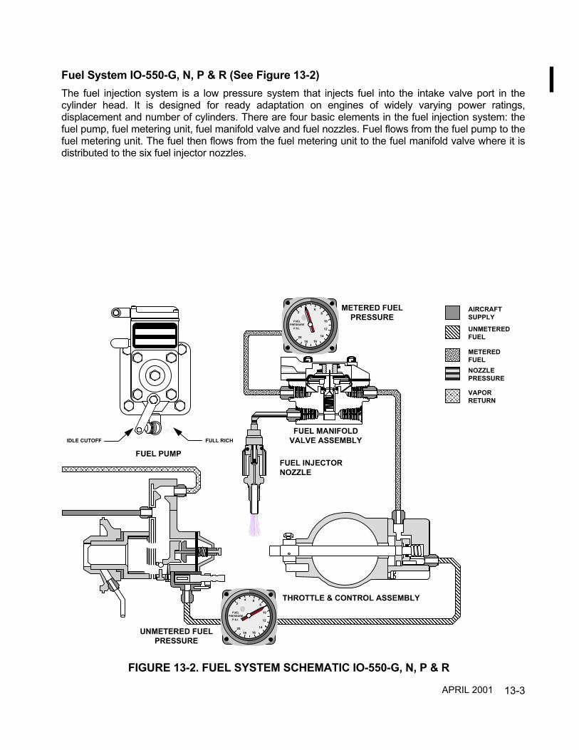
13-3
Fuel System IO-550-G, N, P & R (See Figure 13-2)The fuel injection system is a low pressure system that injects fuel into the intake valve port in thecylinder head. It is designed for ready adaptation on engines of widely varying power ratings,displacement and number of cylinders. There are four basic elements in the fuel injection system: thefuel pump, fuel metering unit, fuel manifold valve and fuel nozzles. Fuel flows from the fuel pump to thefuel metering unit. The fuel then flows from the fuel metering unit to the fuel manifold valve where it isdistributed to the six fuel injector nozzles.
������������������������������������������������������������������������������������������������������������������������������������������������������������������������������������������������������������������������������������������������������������������������������������������������������������������������������������������������������������������������������������������������������������������������������������������������������������������������������������������������������������������������������������������������������������������������������������������������������������������������������������������������������������������������������������������������������������������������������������������������������������������������������������������������������������������������������������������������������������������������������������������������������������������������������������������������
FUEL PUMP
�����������������������������������������������������������������������������������������������������������������������������������������������������������������������������������������������������������������������������������������������������������������������������������������������������������������������������������������������������������������������������������������������������������������������������������������������������������������������������������������������������������������������������������������������������������������������������������������������������������������������������������������������������������������������������������������������������������������������������������������������������������������������������������������������������������������������������������������������������������������������������������������������������������������������������������������������������������������������������������������������������������������������������������������������������������������������������������������������������������������������������������������������������������������������������������������������������������������������������������������������������������������������������������������������������������������������������������������������������������������������������������������������������������������������������������������������������������������������������������������������������������������������������������������������������������������������������������������������������������������������������������������������������������������������������������������������������������������������������������������������������������������������������������������������������������������������������������������������������������������������������������������������������������������������������������������������������������������������������������������������������������������������������������������������������������������������������������������������������������������������������������������������������������������������������������������������������������������������������������������������������������������������������������������������������������������������������������������������������������������������������������������������������������������������������������������������������������������������������������������������������������������������������������������������������������������������������������������������������������������������������������������������������������������������������������������������������������������������������������������������������������������������������������������������������������������������������������������������������������������������������������������������������������������������������������������������������������������������������������������������������������������������������������������������������������������������������������������������������������������������������������������������������������������������������������������������������������������������������������������������������������������������������������������������������������������������������������������������������������������������������������������������������������������������������������������������������������������������������������������������������������������������������������������������������������������������������������������������������������������������������������������������������������������������������������������������������������������������������������������������������������������������������������������������������������������������������������������������������������������������������������������������������������������������������������������������������������������������������������������������������������������������������������������������������������������������������������������������������������������������������
4 68
10
12
141618
20
2
FUELPRESSURE P.S.I.
UNMETERED FUELPRESSURE
IDLE CUTOFF FULL RICH
������������������������������������������������������������������������������������������������������������������������������������������������������������������������������������������������������������������������������������������������������������������������������������������������������������������������������������������������������������������������������������������������������������������������������������������������������������������������������������������������������������������������������������������������������������������������������������������������������������������������������������������������������������������������������������������������������������������������������������������������������������������������������������������������������������������������������������������������������������������������������������������������
����������������������������������������������������������������������������������������������������������������������������������������������������������������
��������������������������������������������������������������������������������������������������������������������������������������������������������������������������������������������������������������������������������������������������������������������������������������������������������������������������������������������������������������������������������������������������������������������������������������������������������������������������������������������������������������������������������������������������������������������������������������������������������������������������������������������������������������������������������������������������������������������������������������������������������������������������������������������������������������������������������������������������������������������������������������������������������������������������������������������������������������������������������������������������������������������������������������������������������������������������������������������������������������������������������������������������������������
4 68
10
12
141618
20
2
FUELPRESSURE P.S.I.
METERED FUELPRESSURE
FUEL MANIFOLDVALVE ASSEMBLY
n
THROTTLE & CONTROL ASSEMBLY
�������������������������������������������������������������������������������������������������������������������������������������������������������������������������������������������
���������������������������������������������������
AIRCRAFTSUPPLY
UNMETEREDFUEL
METEREDFUELNOZZLEPRESSURE
VAPORRETURN
FUEL INJECTORNOZZLE
FIGURE 13-2. FUEL SYSTEM SCHEMATIC IO-550-G, N, P & R
APRIL 2001

13-4
13-2A Altitude Compensating Fuel Pump IO-550-A, B & C (See Figure 13-3A)Fuel enters the fuel pump at the swirl well of the vapor separator. Here, vapor is separatedby a swirling motion so that only liquid fuel is fed to the pump. The vapor is drawn from thetop center of the swirl well by a small pressure-jet of fuel and is fed into the vapor returnline. This line carries the vapor back to the fuel tank. There are no moving parts in thevapor separator, and the only restrictive passage is used in connection with vapor removal.Thus, there is no restriction of main fuel flow.Ignoring the effect of altitude or ambient air conditions for the moment, the use of a positivedisplacement, engine-driven pump means that changes in engine speed affect total pumpflow proportionally. The fuel pump provides greater capacity than is required by the engine.Thus, a recirculation path is provided.By arranging a variable orifice and relief valve in the recirculation path, the pump deliverypressure is maintained proportional to engine speed and ambient air pressure. Thisinsures proper pump pressure and delivery at all engine operating speeds and altitudes.The altitude compensating type fuel pumps utilize an aneroid and rod assembly that assistin controlling fuel flow. The aneroid housing is referenced to ambient air pressure. Theaneroid bellows expands when the air pressure surrounding it decreases. As the aneroidexpands it moves the rod increasing the size of the orifice opening. An increased amountof fuel flows through the orifice to a recirculation path. This decreases fuel flow from thefuel pump to the fuel control unit.A check valve is provided so that boost pressure to the system can by-pass the enginedriven fuel pump during engine starting. This feature also aids in the suppression of vaporformation during high ambient temperature conditions.
APRIL 2001

13-5
FIGURE 13-3A. ALTITUTE COMPENSATING FUEL PUMPDESCRIPTION I0-550-A, B & C
APRIL 2001
13-6
13-2B Standard Fuel Pump IO-550-A, B & C (See Figure 13-3B)Fuel enters the fuel pump at the swirl well of the vapor separator. Here, vapor is separatedby a swirling motion so that only liquid fuel is fed to the pump. The vapor is drawn from thetop center of the swirl well by a small pressure-jet of fuel and is fed into the vapor returnline. This line carries the vapor back to the fuel tank. There are no moving parts in thevapor separator, and the only restrictive passage is used in connection with vapor removal.Thus, there is no restriction of main fuel flow.Ignoring the effect of altitude or ambient air conditions for the moment, the use of a positivedisplacement, engine-driven pump means that changes in engine speed affect total pumpflow proportionally. The fuel pump provides greater capacity than is required by the engine.Thus, a recirculation path is provided.By arranging a variable orifice and relief valve in the recirculation path, the pump deliverypressure is maintained proportional to engine speed. This insures proper pump pressureand delivery at all engine operating speeds.A check valve is provided so that boost pressure to the system can by-pass the enginedriven fuel pump during engine starting. This feature also aids in the suppression of vaporformation during high ambient temperature conditions.
APRIL 2001

13-7
FIGURE 13-3B. STANDARD FUEL PUMP DESCRIPTION I0-550-A, B & C
APRIL 2001

13-8
13-3 Fuel Pump IO-550-G, N, P & R (See Figure 13-4)Fuel enters the fuel pump at the swirl well of the vapor separator. Here, vapor is separatedby a swirling motion so only liquid fuel is fed to the pump. The vapor is drawn from the topcenter of the swirl well by a small pressure-jet of fuel and is fed into the vapor return line.This line carries the vapor back to the fuel tank. There are no moving parts in the vaporseparator, and the only restrictive passage is used in connection with vapor removal. Thus,there is no restriction of main fuel flow.Ignoring the effect of altitude or ambient air conditions for the moment, the use of a positivedisplacement, engine-driven pump means that changes in engine speed affect total pumpflow proportionally. The fuel pump provides greater capacity than is required by the engine.Thus, a recirculation path is provided.The fuel pump incorporates a mixture control valve that routes fuel, through therecirculation path, back to the vapor separator swirl chamber when the mixture controllever is placed in the idle cutoff position. In the idle cutoff position fuel is not allowed to exitthe pump outlet. The recirculation path is blocked in the full rich position. When the mixturecontrol is placed in the full rich position, fuel exits the fuel pump outlet. If the mixturecontrol is placed in an intermediate position fuel flows through the pump outlet and therecirculation path.By arranging a calibrated adjustable orifice and relief valve in the recirculation path, thepump delivery pressure is maintained proportional to engine speed. These provisionsassure proper pump pressure and delivery for all engine operating speeds.A check valve is provided so that boost pressure to the system can by-pass the enginedriven fuel pump during engine starting. This feature also aids in the suppression of vaporformation during high ambient temperature conditions.
APRIL 2001

13-9
FIGURE 13-4. FUEL PUMP DESCRIPTION IO-550-G, N, P & R
APRIL 2001

13-10
13-4 Throttle And Fuel Control Unit IO-550-A, B & C (See Figure 13-5)The function of this assembly is to control engine air intake and to set the metered fuelpressure for proper fuel/air ratio. The air throttle is mounted at the air manifold inlet. Thethrottle valve controls the flow of air to the engine as positioned by the cockpit throttlecontrol lever.Fuel enters the fuel control unit through a strainer and passes to the metering valve. Therotary metering valve has a cam-shaped edge across the fuel delivery port. The position ofthe cam at the port controls fuel flow to the fuel manifold valve and fuel nozzles. The fuelmixture is controlled by the manual mixture control lever in the cockpit that is connected tothe fuel control unit mixture control valve.
FIGURE 13-5. AIR THROTTLE AND FUEL CONTROL GENERAL DESCRIPTIONI0-550-A, B & C
APRIL 2001
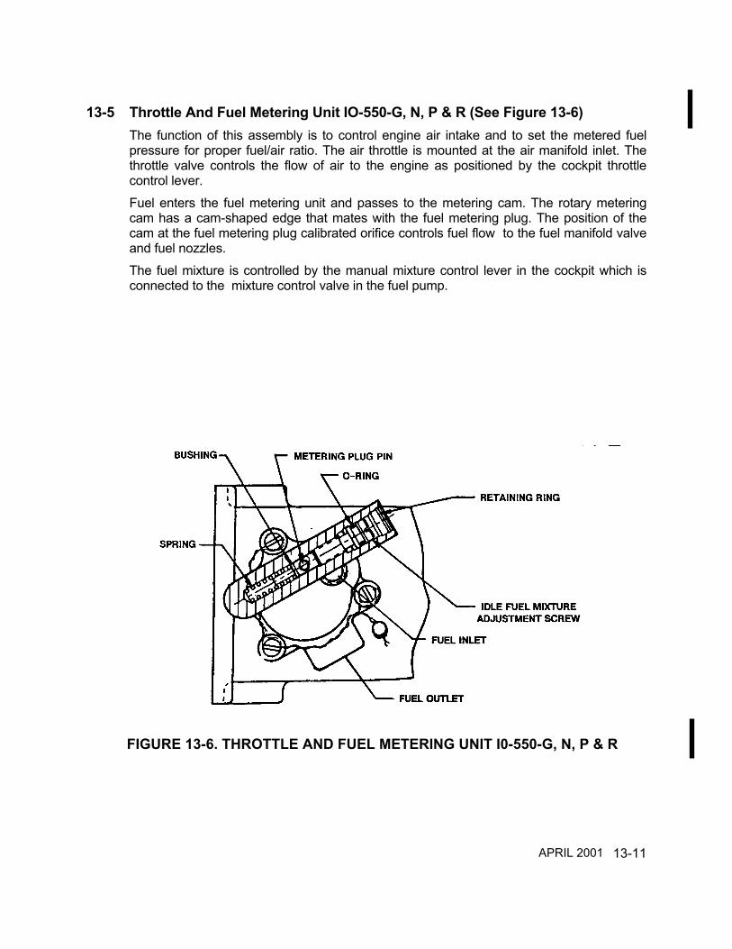
13-11
13-5 Throttle And Fuel Metering Unit IO-550-G, N, P & R (See Figure 13-6)The function of this assembly is to control engine air intake and to set the metered fuelpressure for proper fuel/air ratio. The air throttle is mounted at the air manifold inlet. Thethrottle valve controls the flow of air to the engine as positioned by the cockpit throttlecontrol lever.Fuel enters the fuel metering unit and passes to the metering cam. The rotary meteringcam has a cam-shaped edge that mates with the fuel metering plug. The position of thecam at the fuel metering plug calibrated orifice controls fuel flow to the fuel manifold valveand fuel nozzles.The fuel mixture is controlled by the manual mixture control lever in the cockpit which isconnected to the mixture control valve in the fuel pump.
FIGURE 13-6. THROTTLE AND FUEL METERING UNIT I0-550-G, N, P & R
APRIL 2001

13-12
13-6 Fuel Control Unit IO-550-A, B & C (See Figure 13-7)The fuel control body is made of bronze. The fuel metering shaft and mixture control shaftare made of stainless steel. The metering valve is located at one end and the mixturecontrol valve is located at the other end of the control valve central bore. The valves ride inbushings and are sealed against leakage by o-rings. Loading springs force the valve endsagainst a fixed plug installed in the center of the central bore. This bronze plug has onepassage that mates with the fuel return port and one passage that connects the mixturecontrol valve chamber with the metering valve chamber. O-rings seal this plug in thecentral bore. Each valve includes a groove which forms a fuel chamber. The contouredend face of the mixture control valve aligns with the passages in the metering plug toregulate the fuel flow from the fuel chamber. A control lever is installed on the mixturecontrol valve shaft for connection to the cockpit mixture control. In the metering valve, acam shaped cut is made on the outer part of the end face. A control lever on the meteringvalve shaft is connected to the air throttle valve shaft with linkage. The fuel return port inthe control body connects to the return passage of the metering plug and alignment of themixture control valve face with this passage determines the amount of fuel returned to thefuel pump. A removable plug at the fuel inlet port includes a filter screen to preventadmittance of debris.
FIGURE 13-7. FUEL CONTROL UNIT GENERAL DESCRIPTION I0-550-A, B & C
APRIL 2001
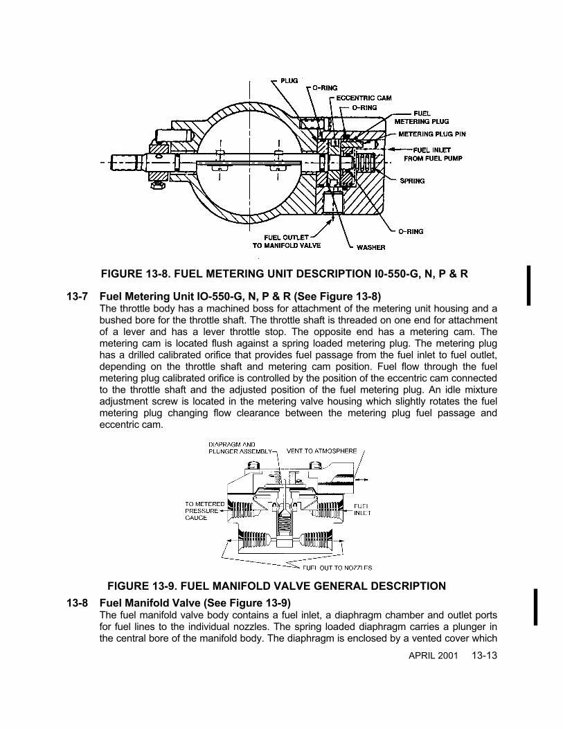
13-13
13-7 Fuel Metering Unit IO-550-G, N, P & R (See Figure 13-8)The throttle body has a machined boss for attachment of the metering unit housing and abushed bore for the throttle shaft. The throttle shaft is threaded on one end for attachmentof a lever and has a lever throttle stop. The opposite end has a metering cam. Themetering cam is located flush against a spring loaded metering plug. The metering plughas a drilled calibrated orifice that provides fuel passage from the fuel inlet to fuel outlet,depending on the throttle shaft and metering cam position. Fuel flow through the fuelmetering plug calibrated orifice is controlled by the position of the eccentric cam connectedto the throttle shaft and the adjusted position of the fuel metering plug. An idle mixtureadjustment screw is located in the metering valve housing which slightly rotates the fuelmetering plug changing flow clearance between the metering plug fuel passage andeccentric cam.
13-8 Fuel Manifold Valve (See Figure 13-9)The fuel manifold valve body contains a fuel inlet, a diaphragm chamber and outlet portsfor fuel lines to the individual nozzles. The spring loaded diaphragm carries a plunger inthe central bore of the manifold body. The diaphragm is enclosed by a vented cover which
FIGURE 13-9. FUEL MANIFOLD VALVE GENERAL DESCRIPTION
FIGURE 13-8. FUEL METERING UNIT DESCRIPTION I0-550-G, N, P & R
APRIL 2001

13-14
retains the diaphragm loading spring. When the plunger is down in the body bore, fuelpassages to the nozzles are closed off. The plunger is drilled for passage of fuel from thediaphragm chamber to its base and the valve within the plunger. As fuel flow increasespressure overcomes diaphragm spring tension causing the plunger to move to the openposition and fuel flows from manifold valve outlets through fuel lines to the fuel nozzleassemblies.
13-9 Fuel Nozzle (See Figure 13-10)The fuel discharge nozzle is located in the cylinder head. The nozzle outlet is screwed intothe tapped fuel nozzle hole in the cylinder head. The nozzle body has a drilled centralpassage with a counterbore at each end. The lower end is the fuel outlet. The upper borecontains a removable jet for calibrating the nozzles. Near the top, radial holes connect theupper counterbore with the outside of the nozzle body for air admission. These holes enterthe counterbore above the orifice and draw outside air through a cylindrical screen fittedover the nozzle body which keeps dirt and foreign material out of the interior of the nozzle.A press-fitted shield is mounted on the nozzle body and extends over the greater part ofthe filter screen, leaving an opening near the bottom. This provides both mechanicalprotection and an air path .Nozzles are calibrated in several ranges and all nozzles furnished for one engine are ofthe same range identified by a letter stamped on the hex of the nozzle body.
FIGURE 13-10. FUEL NOZZLE GENERAL DESCRIPTION
APRIL 2001
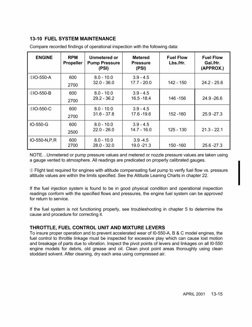
13-15
13-10 FUEL SYSTEM MAINTENANCECompare recorded findings of operational inspection with the following data:
ENGINE RPMPropeller
Unmetered orPump Pressure
(PSI)
MeteredPressure
(PSI)
Fuel FlowLbs./Hr.
Fuel FlowGal./Hr.
(APPROX.)
IO-550-A 6002700
8.0 - 10.032.0 - 36.0
3.9 - 4.517.7 - 20.0 142 - 150 24.2 - 25.6
IO-550-B 6002700
8.0 - 10.029.2 - 36.2
3.9 - 4.516.5 -18.4 146 -156 24.9 -26.6
IO-550-C 6002700
8.0 - 10.031.6 - 37.8
3.9 - 4.517.6 -19.6 152 -160 25.9 -27.3
IO-550-G 6002500
8.0 - 10.022.0 - 26.0
3.9 - 4.514.7 - 16.0 125 - 130 21.3 - 22.1
IO-550-N,P,R 6002700
8.0 - 10.028.0 - 32.0
3.9 -4.519.0 -21.3 150 -160 25.6 -27.3
NOTE…Unmetered or pump pressure values and metered or nozzle pressure values are taken usinga gauge vented to atmosphere. All readings are predicated on properly calibrated gauges.
Flight test required for engines with altitude compensating fuel pump to verify fuel flow vs. pressurealtitude values are within the limits specified. See the Altitude Leaning Charts in chapter 22.
If the fuel injection system is found to be in good physical condition and operational inspectionreadings conform with the specified flows and pressures, the engine fuel system can be approvedfor return to service.
If the fuel system is not functioning properly, see troubleshooting in chapter 5 to determine thecause and procedure for correcting it.
THROTTLE, FUEL CONTROL UNIT AND MIXTURE LEVERSTo insure proper operation and to prevent accelerated wear of I0-550-A, B & C model engines, thefuel control to throttle linkage must be inspected for excessive play which can cause lost motionand breakage of parts due to vibration. Inspect the pivot points of levers and linkages on all I0-550engine models for debris, old grease and oil. Clean pivot point areas thoroughly using cleanstoddard solvent. After cleaning, dry each area using compressed air.
APRIL 2001

13-16
WARNINGWhenever fuel control to throttle linkage, attaching hardware, levers or leverbushings have been replaced or reassembled, the fuel system must be checkedand adjusted in accordance with the "Fuel System Adjustment" chapter and testedin accordance with chapter 22, "Post Maintenance Operational Test". This test isMANDATORY.
NOTE…Linkage connection between the throttle and fuel control unit are the same on the variousI0-550-A, B & C engine models; however, the throttle bodies, throttle levers and fuel control unitlevers used on the different engine models are physically different.
Worn or corroded linkage, attaching hardware, levers or lever bushings must be replaced inaccordance with the IO-550 Permold Series Overhaul Manual, Form X30568A After cleaning,inspection and repair has been accomplished, as required, each pivot point must be lubricatedusing LPS 2, Permatex "Maintain®" Lubricant. If levers, link rods or bushings have been replacedor reassembled, initial lubrication must be accomplished using Shell #5 grease or Lubriplate#630AA or equivalent. Lubrication of levers, link rods or bushings must be performed inaccordance with Figures 13-11, 13-12.Consult the airframe manufacturer and/or their most current published instructions concerningaircraft engine control cable attach point inspection, cleaning, repair, installation and lubrication.After the above procedures have been accomplished verify that each control has full limit of travel,the required safeties are in place, that no binding of levers or linkages is occurring and that controlmovement is unrestricted by contact with other parts or components that are located in closeproximity.
WARNINGWhenever the fuel pump, fuel control unit, fuel manifold valve or fuel injectionnozzles are removed and replaced, the fuel system must be checked and adjustedin accordance with the "Fuel System Adjustment" chapter and tested inaccordance with chapter 22, "Post Maintenance Operational Test" of this manual.
APRIL 1998

13-17
FIGURE 13-11. THROTTLE AND FUEL CONTROL UNIT LUBRICATION I0-550-A, B & C
FIGURE 13-12. THROTTLE AND MIXTURE CONTROL LUBRICATION I0-550-G,N,P & R
APRIL 2001

13-18
Fuel Manifold Valve ReplacementThe fuel manifold valve can be replaced with a new valve, or it can be repaired and calibrated inaccordance with the applicable instructions in the Fuel Injection System Parts And OverhaulManual, Form X30593A, latest revision.
Use the following procedure to remove and replace the fuel manifold valve:1. In accordance with manufacturer’s instructions, remove cowling and any airframe
accessories that may obstruct access to the manifold valve.2. Disconnect the 6 fuel lines from the fuel manifold valve.3. Disconnect the fuel hose from the elbow on the manifold valve.4. Remove the fuel pressure sensing line from its fitting.5. Install protective covers on all open lines and hoses.6. Remove crankcase backbone hardware at manifold bracket.7. Remove the fuel manifold valve and mounting bracket from engine.
CAUTION...Never use Teflon tape on fuel injection system fittings.
8. Fittings from the original manifold valve may be installed and oriented to the same positionin the replacement manifold valve. The fittings must be clean and free of damage and debrisprior to installation. Apply F/I sealant to tapered male threads in accordance with Figure 13-14. Install fittings in fuel manifold valve and orient to the original positions. Torque fittings inaccordance with Table 2, “Torque Specifications For Hose Fittings.”
9. If replacement manifold valve does not include a mounting bracket, remove the existing
bracket from the old manifold valve as follows:10. Cut, remove and discard lockwire.11. Remove 4 screws and 4 lock washers. Discard lock washers.12. Remove bracket and 4 plain washers from old manifold valve.13. Manifold valve bracket and hardware must be cleaned with mineral spirits solvent and dried.
Inspect all screw threads to insure that none are damaged.14. Orient manifold valve bracket on new manifold valve using 4 plain washers and secure with
4 new lock washers and 4 screws.
15. Torque screws to 20 ±1 inch pounds and lockwire in accordance with “Typical LockwireProcedure” in chapter 6.
WARNINGWhile installing the bracket, do not displace or tear manifold valve diaphragm.16. Position manifold and bracket assembly over crankcase backbone mounting holes. Install
manifold/bracket assembly to backbone with 2 screws, washers, and nuts. Torque to 180-220 inch pounds .
APRIL 2001

13-19
17. Remove all protective covers from fuel lines and hoses, and reinstall fuel lines to themanifold valve. Insure that B-nut threads are clean and free of damage.
18. Torque fuel line to nozzle nuts to 40 - 45 inch pounds. Torque fuel line to manifold valvenuts to 55 - 60 inch pounds.
19. Torque fuel inlet hose “B” nut and fuel pressure sensing line “B” nut to manifold valveelbows in accordance with Table 2, “Torque Specifications For Hose Fittings.”
20. Reinstall removed airframe components in accordance with airframe manufacturer’sinstructions.
21. After all requirements of scheduled maintenance have been performed and prior to anyengine operation, a complete fuel system leak check must be performed in accordance withthe aircraft manufacturer or STC holder’s information.
Fuel Nozzle Removal, Cleaning and Replacement1. Remove cowling and any airframe accessories that may obstruct access to the fuel nozzles
in accordance with the airframe manufacturer’s instructions2. Loosen and remove the fuel line from the fuel injector nozzle assembly.3. Loosen and remove the fuel nozzle.4. Clean nozzle by soaking in lacquer thinner, methyl ethyl keytone or acetone for several
hours.5. If a nozzle is obstructed and cannot be cleaned by solvent action, it must be replaced with a
new nozzle. CAUTION...Do not attempt to clear nozzle obstruction with wire.
6. Apply TCM 646943 antiseize lubricant to cylinder end of nozzle threads in accordance withFigure 13-14B. Reinstall the nozzle and torque to 55 - 65 inch pounds.
7. Install fuel line on nozzle.8. Torque the fuel line “B” nut to 40 - 45 inch pounds.9. Reinstall all airframe supplied accessories and cowling in accordance with the airframe
manufacturer’s instructions.10. After all requirements of scheduled maintenance have been performed and prior to any
engine operation, a complete fuel system leak check must be performed in accordance withthe aircraft manufacturer or STC holder’s information.
APRIL 2001
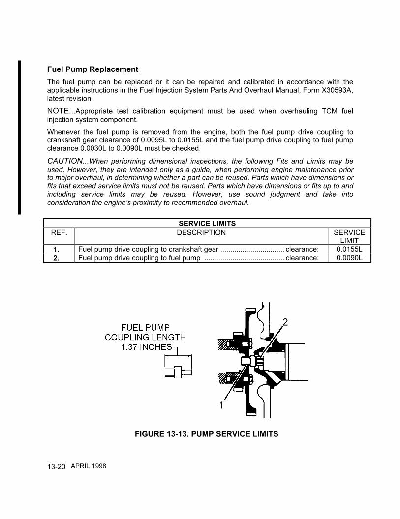
13-20
Fuel Pump ReplacementThe fuel pump can be replaced or it can be repaired and calibrated in accordance with theapplicable instructions in the Fuel Injection System Parts And Overhaul Manual, Form X30593A,latest revision.
NOTE...Appropriate test calibration equipment must be used when overhauling TCM fuelinjection system component.Whenever the fuel pump is removed from the engine, both the fuel pump drive coupling tocrankshaft gear clearance of 0.0095L to 0.0155L and the fuel pump drive coupling to fuel pumpclearance 0.0030L to 0.0090L must be checked.
CAUTION...When performing dimensional inspections, the following Fits and Limits may beused. However, they are intended only as a guide, when performing engine maintenance priorto major overhaul, in determining whether a part can be reused. Parts which have dimensions orfits that exceed service limits must not be reused. Parts which have dimensions or fits up to andincluding service limits may be reused. However, use sound judgment and take intoconsideration the engine’s proximity to recommended overhaul.
SERVICE LIMITSREF. DESCRIPTION SERVICE
LIMIT1. Fuel pump drive coupling to crankshaft gear ................................ clearance: 0.0155L2. Fuel pump drive coupling to fuel pump ........................................ clearance: 0.0090L
FIGURE 13-13. PUMP SERVICE LIMITS
APRIL 1998

13-21
Fuel Pump Replacement (continued)
1. Remove any airframe components required to gain access to the fuel pump in accordancewith the airframe manufacturer’s instructions. Remove the following hoses from their fittingson the fuel pump and install protective covers on the hose ends. Identify fuel line location forproper reinstallation:a. Airframe to engine fuel connections in accordance with the airframe manufacturer’s
instructions.b. Vapor return hosec. Fuel outlet (unmetered pressure) hose.
2. Remove mixture control cable connection in accordance with the airframe manufacturer’sinstructions.
3. Remove the nuts and washers that hold the fuel pump on the crankcase:a. 2 plain nutsb. 2 lock washersc. 2 hold down washersDiscard lock washers.
CAUTION...Do not allow the coupling to fall into the crankcase. If it does, you must retrieve itbefore proceeding.
4. Carefully remove the fuel pump, coupling, and gasket.5. Discard gasket.6. Inspect hoses for condition. Replace any hose that exhibits wear or deterioration.7. Discard worn or damaged parts.8. The fuel pump can be replaced or repaired and calibrated in accordance with the applicable
instructions in the Fuel Injection System Parts And Overhaul Manual, Form X30593A, latestrevision.
9. Fittings from the original fuel pump may be installed and oriented to the same position inthe replacement pump.
CAUTION...Never use Teflon tape on fuel injection system fittings.
10. The fittings must be clean and free of damage and debris prior to installation. Apply F/Isealant to tapered male threads in accordance with Figure 13-14A. Install fittings in fuelpump and orient to the original positions.
11. Apply a small amount of Gasket Maker to the crankcase split lines above and below the fuelpump bore.
12. Apply Molyshield Grease to the coupling receptacle on the fuel pump.13. Insert the fuel pump coupling into the coupling receptacle on the fuel pump. Insure that the
coupling is fully seated .
APRIL 2001
13-22
14. Install the new gasket on the crankcase fuel pump bore studs.15. Install the fuel pump on the crankcase by sliding the fuel pump on the fuel pump mounting
studs while carefully guiding the fuel pump coupling into the square hole in the crankshaftgear.
16. Install hold-down washers, new lock-washers, and nuts on each stud.17. Torque the fuel pump nuts to 180 - 220 inch pounds.18. Flush the fuel supply hose into an appropriate container prior to reconnecting.19. Install fuel hoses on fuel pump. Torque fuel pump hose connections in accordance with
Table 2, “Torque Specifications for Hose Fittings.”20. Reinstall cowling and airframe accessories in accordance with the airframe manufacturer’s
instructions.21. After all requirements of scheduled maintenance have been performed and prior to any
engine operation, a complete fuel system leak check must be performed in accordance withthe aircraft manufacturer or STC holder’s information.
Throttle and Fuel Control Unit/Throttle and Fuel Metering Unit Replacement1. I0-550-A throttle and fuel control units must be replaced in accordance with the airframe
manufacturer’s instructions.2. On I0-550-B, C, G, P & R model engines, remove any airframe components required to gain
access to the throttle and fuel control unit/throttle and fuel metering unit in accordance withthe airframe manufacturer’s instructions. Remove the following hoses from their fittings.a. Fuel hose from fuel control unit/fuel metering unit to manifold valve.b. Fuel hose(s) from fuel pump to fuel control unit/fuel metering unit.
3. Install protective covers on all loose hose ends.4. On I0-550-B model engines, remove the throttle to induction manifold clamp and hose.
Remove two bolts and washers and remove throttle and fuel control as a unit. On I0-550-Cmodel engines, remove the throttle to induction elbow clamps and hoses. Loosen andremove upper throttle support brackets and hardware in accordance with the airframemanufacturer’s instructions. Remove nut from lower throttle body support bracket andremove throttle and fuel control as a unit. On I0-550-G, N, P and R model engines removefour bolts, two washers, two lock washers and separate throttle from intake manifold.Remove and discard throttle gasket and discard lock washers.
5. Inspect hoses for condition. Replace any hose that exhibits wear, damage, or deterioration.6. Remove and inspect all fittings for cleanliness and damaged threads. Replace fittings that
are damaged.7. TCM offers rebuilt fuel injection system components as an alternative to field repair of
components. The throttle and fuel metering unit can be repaired and calibrated inaccordance with the applicable instructions in the Fuel Injection System Parts And OverhaulManual, Form X30593, latest revision.
APRIL 2001

13-23
8. Fittings from the original fuel control unit/fuel metering unit may be installed and oriented tothe same positions in the new or replacement fuel assembly. The fittings must be clean andfree of damage and debris prior to installation. Apply F/I sealant to tapered male threads inaccordance with Figure 13-14. Install fittings and orient to the original positions. Torquefittings in accordance with Table 2, “Torque Specifications For Hose Fittings.”
CAUTION...Never use Teflon tape on fuel injection system fittings.
9. Install I0-550-A model engine throttle and control assembly in accordance with the airframemanufacturer’s instructions.
10. On I0-550-B and C model engines, using serviceable hoses and clamp assemblies, installthe throttle and fuel control unit/throttle and metering unit on the intake manifold. Tightenhose clamps sufficiently to insure complete engagement and security of hose. Do not overtighten clamps to the point of cold flow.
11. On I0-550-B engines, install serviceable throttle and control unit on oil sump and secure withtwo washers and bolts. Torque bolts to 155-175 inch pounds. Install lock wire on bolts inaccordance with chapter 9.
12. On I0-550-C model engines, align throttle stud with lower support bracket and install nut.Torque nut to 90-110 inch pounds. Install upper throttle support brackets and hardware inaccordance with the airframe manufacturer’s instructions.
13. On I0-550-G, N, P and R model engines, using a new gasket, install serviceable throttle andfuel metering unit on the intake manifold. Secure using four washers, four new lock washersand four bolts. Torque bolts to 75-85 inch pounds.
CAUTION...Torque all hose connections and fittings in accordance with Table 2, “TorqueSpecifications For Hose Fittings” later in this chapter.
14. Install the following hoses:
a. Remove protective cover and install fuel hose from throttle and fuel control unit/throttleand fuel metering unit to manifold valve.
b. Remove protective cover and install fuel hose(s) from fuel pump to throttle and meteringunit.
15. Reinstall cowling and airframe accessories in accordance with the airframe manufacturer’sinstructions.
16. After all requirements of scheduled maintenance have been performed and prior to anyengine operation, a complete fuel system leak check must be performed in accordance withthe aircraft manufacturer or STC holder’s information .
APRIL 1998

13-24
Fuel Line ReplacementUse the following procedure to remove and replace an existing manifold valve to nozzle fuelline:1. Separate fuel line from fuel line support bracket and clamp.2. Disconnect the fuel line at the manifold valve.3. Disconnect the fuel line at the fuel nozzle and remove fuel line.4. Position a new or existing serviceable fuel line on the engine and connect it to the fuel
manifold valve. Torque to 55 - 60 inch pounds.5. Install the fuel line on the fuel nozzle. Torque B-nut to 40 - 45 inch pounds.6. Install the fuel line into the fuel line support bracket and clamp.7. If the rubber fuel line protector is damaged, replace it with a new protector.8. After all requirements of scheduled maintenance have been performed and prior to any
engine operation, a complete fuel system leak check must be performed in accordance withthe aircraft manufacturer or STC holder’s information.
Fuel Hose ReplacementIf a fuel hose is damaged, worn, chaffed, or deteriorated, replace it in accordance with the followingprocedure:1. Remove any airframe supplied support hardware from fuel hose in accordance with the airframe
manufacturer’s instructions. Remove fuel hose from its elbows. Drain fuel into a suitablecontainer.
2. Inspect elbow threads for damage. Remove and replace elbow in accordance with thepreceding component fitting installation instructions if damaged or worn.
3. Install new, clean fuel hose on elbows. The fuel hose must be routed in it’s original positionaway from any heat source and any airframe support hardware that was removed must bereinstalled in accordance with the airframe manufacturer’s instructions.
4. Torque hose fittings in accordance with Table 2, “Torque Specifications For Hose Fittings5. After all requirements of scheduled maintenance have been performed and prior to any engine
operation, a complete fuel system leak check must be performed in accordance with the aircraftmanufacturer or STC holder’s information.
APRIL 1998

13-25
FIGURE 13-14A. GENERAL F/I SEALANT APPLICATION
FIGURE 13-14B. GENERAL FUEL NOZZLE ANTI-SEIZE APPLICATION
APRIL 2001

13-26
TABLE 1. TORQUE SPECIFICATIONS FOR FITTINGSSIZE FITTING AND MATERIAL TUBE O.D. INCH POUNDS
5/16-24 #2 (Brass/Aluminum) .125 15-305/16-24 #2 (Steel) .125 15-503/8-24 #3 (Brass/Aluminum) .188 40-653/8-24 #3 (Steel) .188 50-907/16-20 #4 (Brass/Aluminum) .250 60-807/16-20 (Steel) .250 70-1207/16-24 #4 (Steel) .190 60-809/16-18 #6 (Brass/Aluminum) .375 75-1259/16-18 #6 (Steel) .375 90-1503/4-16 #8 (Brass/Aluminum) .500 150-2503/4-16 #8 (Steel) .500 135-2507/8-14 #10 (Brass/Aluminum) .625 200-3507/8-14 #10 (Steel) .625 300-400
TABLE 2. TORQUE SPECIFICATIONS FOR HOSE FITTINGS
HOSE SIZE THREAD SIZE FITTING MATERIAL INCH POUNDS
# 2 (5/16-24) Hose End Fitting To Brass/Allum. FittingHose End Fitting To Steel Fitting
50-8075-120
# 3 (3/8-24) Hose End Fitting To Brass/Allum. FittingHose End Fitting To Steel Fitting
70-10595-140
# 4 (7/16-20) Hose End Fitting To Brass/Allum. FittingHose End Fitting To Steel Fitting
100-140135-190
# 5 (1/2-20) Hose End Fitting To Brass/Allum. FittingHose End Fitting To Steel Fitting
130-180170-240
# 6 (9/16-18) Hose End Fitting To Brass/Allum. FittingHose End Fitting To Steel Fitting
150-195215-280
# 8 (3/4-16) Hose End Fitting To Brass/Allum. FittingHose End Fitting To Steel Fitting
270-350470-550
# 10 (7/8-14) Hose End Fitting To Brass/Allum. FittingHose End Fitting To Steel Fitting
360-430620-745
# 12 (1-1/16-12) Hose End Fitting To Brass/Allum. FittingHose End Fitting To Steel Fitting
460-550855-1055
APRIL 2001

13-27
INTENTIONALLY
LEFT
BLANK
14-1
CHAPTER 14
INDUCTION SYSTEM
SECTION PAGE14-2 Induction System Description I0-550-A, B & C ............ 14-214-3 Induction System Description I0-550-G, N, P & R ....... 14-314-3 Induction System Maintenance .................................... 14-414-4 Induction System Maintenance .................................... 14-5
FIGURE PAGE14-1 General Induction System Schematic
I0-550-A, B & C.......................................................... 14-214-2 General Induction System Schematic
I0-550-G, N, P & R..................................................... 14-314-3 General Air Throttle Assembly Description
I0-550-A, B & C.......................................................... 14-4
APRIL 2001

14-2
14-1 INDUCTION SYSTEM DESCRIPTION I0-550-A, B & CEngine components through which air flows following the aircraft air inlet filter/alternate air doorare: throttle assembly, manifold, induction tubes and cylinder intake ports. Air flows throughthese components in the order they are listed.Refer to the aircraft manufacturer's Airplane Flight Manual (AFM) for alternate air dooroperations.The intake manifold is an air distribution system mounted below the engine cylinders. It servesto carry induction air to the individual cylinder intake ports.The cylinder intake ports are cast into the cylinder head assembly. Air from the manifold iscarried into the intake ports, mixed with fuel from the injector nozzles where it enters thecylinder as a combustible mixture when the intake valve opens.
FIGURE 14-1. GENERAL INDUCTION SYSTEM SCHEMATIC I0-550-A, B & C
APRIL 2001

14-3
14-2 INDUCTION SYSTEM DESCRIPTION I0-550-G, N, P & REngine components through which air flows following the aircraft air inlet filter/alternate air doorare: throttle assembly, manifold, induction tubes and cylinder intake ports. Air flows throughthese components in the order they are listed.Refer to the aircraft manufacturer's Airplane Flight Manual (AFM) for alternate air dooroperations.The intake manifold is an air distribution system mounted above the engine cylinders. It servesto carry induction air to the individual cylinder intake ports.The cylinder intake ports are cast into the cylinder head assembly. Air from the manifold iscarried into the intake ports, mixed with fuel from the injector nozzles where it enters thecylinder as a combustible mixture when the intake valve opens.
AIRCRAFTINLET AIR IN
TOP VIEW OF ENGINEWITH INDUCTION
MANIFOLD INSTALLED
CLAMPS ANDHOSES
#5
#3
#1
#6
#2
#4
THROTTLE ANDMETERING UNIT
THROTTLEBUTTERFLY
AIRFLOW
FIGURE 14-2. GENERAL INDUCTION SYSTEM SCHEMATIC I0-550-G, N, P & R
APRIL 2001

14-4
14-3 INDUCTION SYSTEM COMPONENT DETAILED DESCRIPTIONAir Throttle Assembly I0-550-A, B & C - The air throttle assembly is an aluminum casting thatcontains the shaft and throttle valve assembly. The throttle bore area is tailored to the enginesize. No venturi or other restriction is used. The shaft bosses contain bushings in which theshaft rides. Wave washers provide protection against vibration. An idle speed adjusting screwis provided in one of the throttle valve shaft levers and bears against a stop pin installed in thethrottle body.NOTE…See chapter 13 for a detail description of the I0-550-G, N, P & R throttle and meteringunit.
���������������������������������������������������
STOP PINLEVER
THROTTLE PLATEPLAINWASHER
PLAINWASHER
WAVEWASHER COLLAR
THROTTLESHAFT
THROTTLE BUSHING
FIGURE 14-3. GENERAL AIR THROTTLE ASSEMBLY DESCRIPTION I0-550-A, B & C
APRIL 2001
14-5
14-4 INDUCTION SYSTEM MAINTENANCEInduction System - Induction system maintenance is limited to removal and replacement ofmalfunctioning components and tightening loose connections in accordance with the applicableportions of the IO-550 Permold Overhaul Manual, Form X30568A Induction Systemdisassembly and reassembly procedures.Lubrication - Throttle linkage, levers, and bushings must be cleaned, inspected and lubricatedin accordance with the instructions in chapter 13, "Throttle, Fuel Control Unit And MixtureLevers. "
APRIL 1998

14-6
INTENTIONALLY
LEFT
BLANK

15-1
CHAPTER 15
OPTIONAL EQUIPMENT
SECTION PAGE15-1 Air Conditioning System Description .........................15-215-2 Air Conditioning System Component.........................15-215-3 Detail Description .......................................................15-215-4 Maintenance...............................................................15-3
FIGURE PAGE15-1 Optional Freon Compressor Drive .............................15-215-2 Checking Sheave Alignment......................................15-315-3 Sheave Alignment ......................................................15-415-4 Belt Tensioning ..........................................................15-5
APRIL 1998
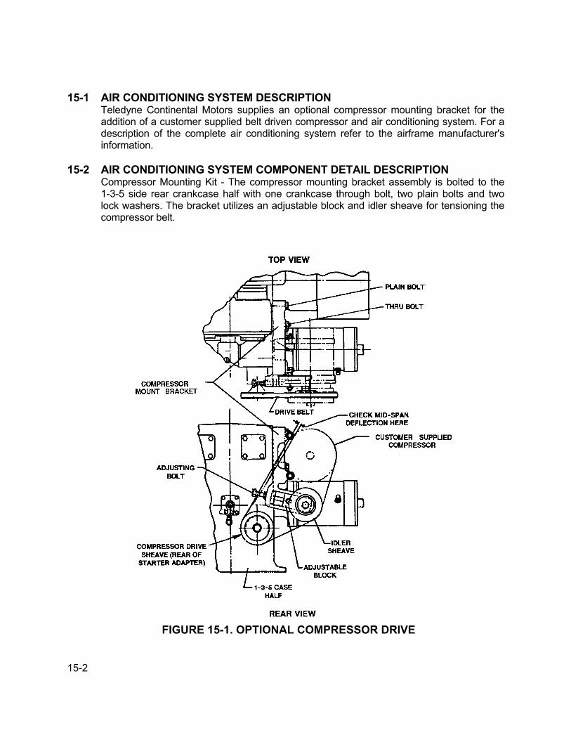
15-2
15-1 AIR CONDITIONING SYSTEM DESCRIPTIONTeledyne Continental Motors supplies an optional compressor mounting bracket for theaddition of a customer supplied belt driven compressor and air conditioning system. For adescription of the complete air conditioning system refer to the airframe manufacturer'sinformation.
15-2 AIR CONDITIONING SYSTEM COMPONENT DETAIL DESCRIPTIONCompressor Mounting Kit - The compressor mounting bracket assembly is bolted to the1-3-5 side rear crankcase half with one crankcase through bolt, two plain bolts and twolock washers. The bracket utilizes an adjustable block and idler sheave for tensioning thecompressor belt.
FIGURE 15-1. OPTIONAL COMPRESSOR DRIVE

15-3
15-3 MAINTENANCERemove and replace worn or malfunctioning components in accordance with applicableportions of disassembly, reassembly in the IO-550 Permold Series Overhaul Manual,Form X30568A, Chapter 11 and the following:Premature belt replacement can usually be attributed to improper alignment of thesheaves, bent sheaves and/or improper belt tensioning. Use the following instructions tocorrect this problem.The alignment of compressor, starter adapter and idler sheaves must be checked usingBorroughs Tool Number 8082 alignment tool. Check tool flatness (calibration) by laying iton a surface table. Place the alignment tool around the drive sheave with the extendedend overlaying the upper portion of the compressor sheave. When the alignment is correctthe alignment tool extended end (bar center) will fall within 0.020 inch of the center of thesheave. Use this same procedure to check the idler sheave, except the extended end ofalignment tool will overlay the lower portion of the compressor sheave. See Figure 15-2,"Checking Sheave Alignment." Repeat each step with drive sheave rotated approximately90° to insure drive sheave is not warped.If drive sheave or idler are not in alignment, remove sheaves and install up to but do notexceed five 0.020 shims [P/N 643956-20] to achieve the correct alignment. See Figure15-3, "Sheave Alignment." When idler sheave is properly adjusted torque sheave screw to300-350 inch pounds torque. When drive sheave is properly adjusted, torque sheave12-point, self- locking nut to 450-500 inch pounds. Nuts must be lubricated with cleanaviation engine oil. All threads of sheave nut must be engaged.
FIGURE 15-2. CHECKING SHEAVE ALIGNMENT
APRIL 1998

15-4
CAUTION…Prevent engine from turning when torquing nut.
See Figure 15-4, "Belt Tensioning," on next page. Loosen the jam nut, adjusting bolt andslide nut. The slide nut should be loosened only enough to allow the slide to move freelyand the adjusting bolt should be turned out far enough to allow installation of the belt.
Install the drive belt. Slide the idler pulley snugly against the belt and tighten the adjustingbolt finger tight into its socket. In this position the idler sheave should be rotatable by handunder the belt. Tighten the adjusting bolt two full turns. Torque the adjusting bolt jam nut to275-375 inch pounds torque. Torque the idler sheave screw to 300-350 inch pounds.Confirm belt tension is 50-70 pounds by one of the following methods:
1. Use a direct reading belt tension gage such as Borroughs Tool NumberBT-33-73F.
2. Measure belt deflection under a five pound load at the center of the longest beltspan. Correct deflection is 0.30- 0.40 inch.
If belt tension is not within the above tolerance, loosen jam nut and slidenut, readjust belttension. One full turn of adjusting screw will give approximately ten pounds change in belttension.CAUTION…Do not over tighten drive belt.
After approximately five hours of operation, recheck belt tension and adjust as required tomaintain 50-70 pounds belt tension.
FIGURE 15-3. SHEAVE ALIGNMENT
APRIL 1998
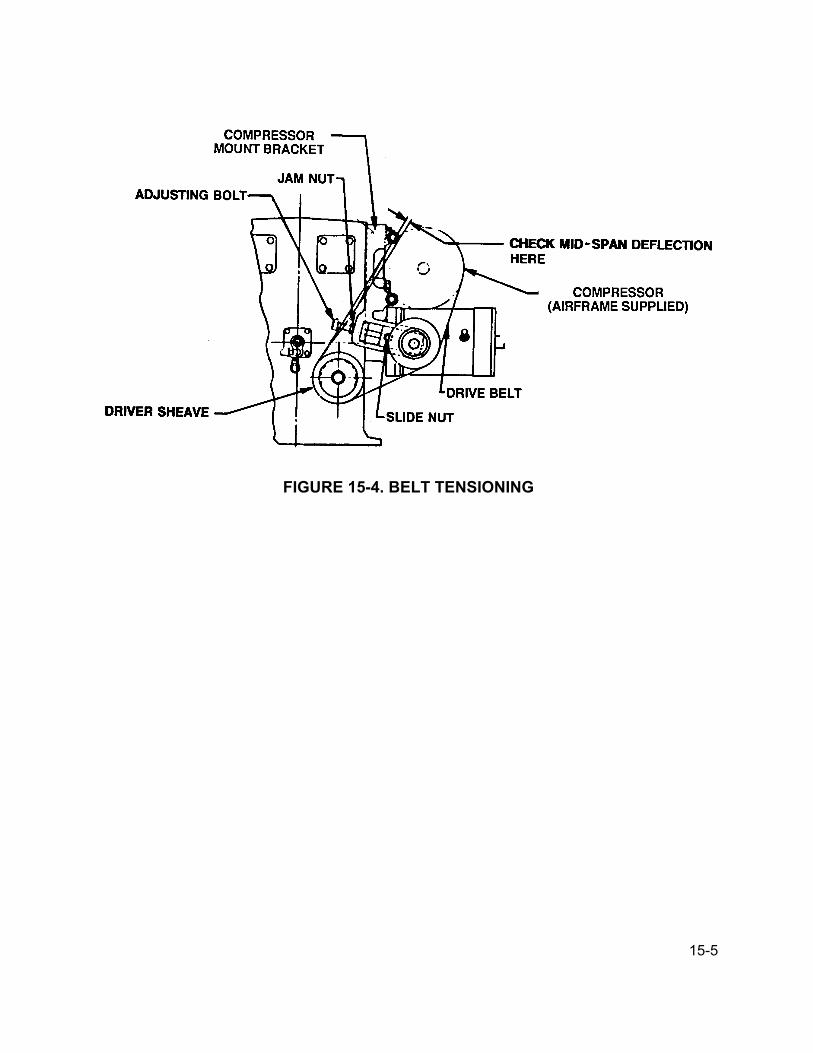
15-5
FIGURE 15-4. BELT TENSIONING

15-6
INTENTIONALLY
LEFT
BLANK

16-1
CHAPTER 16
ELECTRICAL CHARGING SYSTEM
SECTION PAGE16-1 Electrical Charging System Description ...............................16-216-2 Electrical Charging System Component
Detailed Description .............................................................16-316-3 Electrical Charging System Maintenance.............................16-3
FIGURE PAGE16-1 General Alternator Location..................................................16-2
APRIL 1998
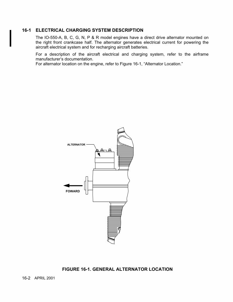
16-2
16-1 ELECTRICAL CHARGING SYSTEM DESCRIPTIONThe IO-550-A, B, C, G, N, P & R model engines have a direct drive alternator mounted onthe right front crankcase half. The alternator generates electrical current for powering theaircraft electrical system and for recharging aircraft batteries.For a description of the aircraft electrical and charging system, refer to the airframemanufacturer’s documentation.For alternator location on the engine, refer to Figure 16-1, “Alternator Location.”
ALTERNATOR
FOWARD
FIGURE 16-1. GENERAL ALTERNATOR LOCATION
APRIL 2001

16-3
16-2 ELECTRICAL CHARGING SYSTEM COMPONENT DETAILED DESCRIPTIONFor detailed information about TCM alternators, refer to “Alternator Service Instructions,”Form X30531-3.
16-3 ELECTRICAL CHARGING SYSTEM MAINTENANCEFor maintenance or repair of TCM alternators, refer to TCM Form X30531-3, “AlternatorService Instructions.” The alternators may be removed for repair or replacement inaccordance with the following removal and replacement instructions.CAUTION...When an alternator is removed that has a grounding strap, the strap must bereinstalled with the new or rebuilt alternator.
Direct Drive AlternatorRemoval and Replacement
Removal1. Disconnect electrical connections from alternator in accordance with airframe
manufacturer’s instructions.2. Remove plain washer, lock washer, and nut from the four mounting studs.3. Discard lockwashers.
4. Remove the alternator from the mounting studs.
5. Remove gasket from mounting studs
Alternator Drive HubSlippage InspectionWhenever the alternator is removed, perform the following drive gear hub slippageinspection.1. The torque required to slip the elastomer coupling when new must be 180 inch pounds
(15 foot pounds) torque minimum measured after 45° of revolution at a rate of 1 to 2degrees per second.
2. Slippage must occur at the outside diameter of elastomer with no damage to theelastomer.
3. On couplings which have been in service for more than 25 hours, slippage torque mustnot be less than 140 inch pounds (11.7 foot pounds) torque.
4. Drive hubs that do not conform with the above specifications must be discarded.
APRIL 1998
16-4
Repair/Replacement1. Alternator repair/replacement must be performed in accordance with TCM Alternator
Maintenance and Parts Catalog, Form X30531A.Installation1. Install new gasket on new or rebuilt alternator.2. Install alternator assembly on mounting studs with four plain washers, four new lock
washers, and four plain nuts.3. Torque nuts to 180 - 220 inch pounds.4. Install all electrical connections in accordance with airframe manufacturer’s instructions.
APRIL 1998

17-1
CHAPTER 17
STARTING SYSTEM
SECTION PAGE17-1 Starter And Starter Adapter Description ....................... 17-217-2 Starting System Component Detail Description ........... 17-317-3 Starting System Maintenance....................................... 17-4
FIGURE PAGE17-1 Starter And Starter Drive Adapter Description.............. 17-217-2 Starter Adapter Description .......................................... 17-317-3 Starter Adapter Fits And Limits..................................... 17-517-4 Customer Spec. Starter Adapter Fits and Limits .......... 17-717-5 Shaftgear Drum Dimensions ........................................ 17-817-6 Worm Wheel Drum Dimensions ................................... 17-8
APRIL 1998

17-2
17-1 STARTER AND STARTER ADAPTER DESCRIPTIONThe I0-550 Permold Series engines utilize a starting system that employs an electric startermotor mounted on a right angle starter to engine adapter. The right angle drive adapterserves to shorten engine overall length. As the starter motor is electrically energized, theadapter worm shaft and gear engage the starter shaftgear by means of a spring and clutchassembly. As the shaftgear rotates, it in turn rotates the crankshaft gear and crankshaft.When the engine starts and accelerates, the gripping action of the clutch spring is relieved,disengaging the shaftgear from the worm shaft and electric starter motor.
FIGURE 17-1. STARTER AND STARTER ADAPTER DESCRIPTION
APRIL 1998

17-3
17-2 STARTING SYSTEM COMPONENT DETAIL DESCRIPTIONStarter - For a detailed description of TCM electric starter motors See TCM Form X30592,Starter Service InstructionsStarter Adapter - The starter adapter assembly uses a worm drive gear shaft and worm gearto transfer torque from the starter motor to the clutch assembly. The shaft is supported in thehousing at the starter end by a ball bearing and retaining ring, the opposite end is supportedby a needle bearing pressed into the adapter housing. As the worm gear rotates the wormwheel and clutch spring, the clutch spring is tightened around the drum of the startershaftgear. As the shaftgear turns, its torque is transmitted directly to the crankshaft gear. Thestarter shaftgear is supported at the adapter cover by a pressed in ball bearing, and issupported at the opposite end by a needle bearing pressed into the 1-3-5 crankcase half.
FIGURE 17-2. STARTER ADAPTER DESCRIPTION
APRIL 1998

17-4
17-3 STARTING SYSTEM MAINTENANCEThe starter motor may be removed for repair or maintenance in accordance with applicableportions of starter and starter adapter disassembly/ reassembly instructions in the I0-550Permold Series Overhaul Manual, Form X30568A.Disassembly, maintenance and reassembly of the starter motor must be performed inaccordance with the Starter Service Instructions, Form X30592.
When performing starter adapter repairs prior to engine TBO the following dimensional limitsmay be used.
CAUTION...When performing dimensional inspection the following "Service Limits" may beused. However, they are only intended as a guide for re-use when performing maintenanceof the engine prior to major overhaul. Parts with dimensions or fits that exceed service limitsmust not be re-used. Parts with values up to and including service limits may be re-used,however, judgment should be exercised considering the PROXIMITY of the engine to itsrecommended overhaul time.
SERVICE LIMITS
REF. DESCRIPTION SERVICELIMIT
1. Starter shaftgear needle bearinq hole crankcase ....................... Diameter: 1.00052. Starter shaft gear front (bearinq) journal ..................................... Diameter: 0.74803. Starter shaftgear in clutch drum bearinq..................................... Diameter: 1.0000L4. Clutch spring sleeve in starter adapter........................................ Diameter: 0.0050T5. Starter shaft gear in ball bearing................................................. Diameter: 0.0005L6. Bearing in starter adapter cover.................................................. Diameter: 0.0010L7. Worm wheel gear .............................................................. End Clearance: 0.02508. Worm wheel drum ...................................................................... Diameter: See Figure
17-69. Starter Shaft gear drum............................................................... Diameter: See Figure
17-510. Clutch spring in clutch sprinq sleeve ......................................... Diameter: 0.0030T11. From center line of worm gearshaft to starter adapter thrust pads ............ : 0.252012. Needle bearing hole starter adapter ........................................... Diameter: 0.749513. Ball bearing in starter adapter ..................................................... Diameter: 0.0010L14. Worm gearshaft in needle bearing area...................................... Diameter: 0.560015. Worm gearshaft in ball bearing ................................................... Diameter: 0.0007L16. Starter worm gear on shaft.......................................................... Diameter: 0.0040L17. Starter spring on worm drive shaft .............................................. Diameter: 0.0250L18. Starter pilot to starter drive adapter............................................. Diameter: 0.0070L19. Starter drive tongue to worm shaft drive slot..................... Side Clearance: 0.0340L20. Starter worm wheel gear and worm gear ................................... Backlash: 0.020021. Starter adapter Cover Pilot In Adapter Housing ......................... Diameter: 0.0040L
T=Tight L=Loose When sand blasted diameter finish is smoother than 75 RMS, replace sleeve.
APRIL 2001

17-5
FIGURE17-3. STARTER ADAPTER FITS AND LIMITS
APRIL 1998
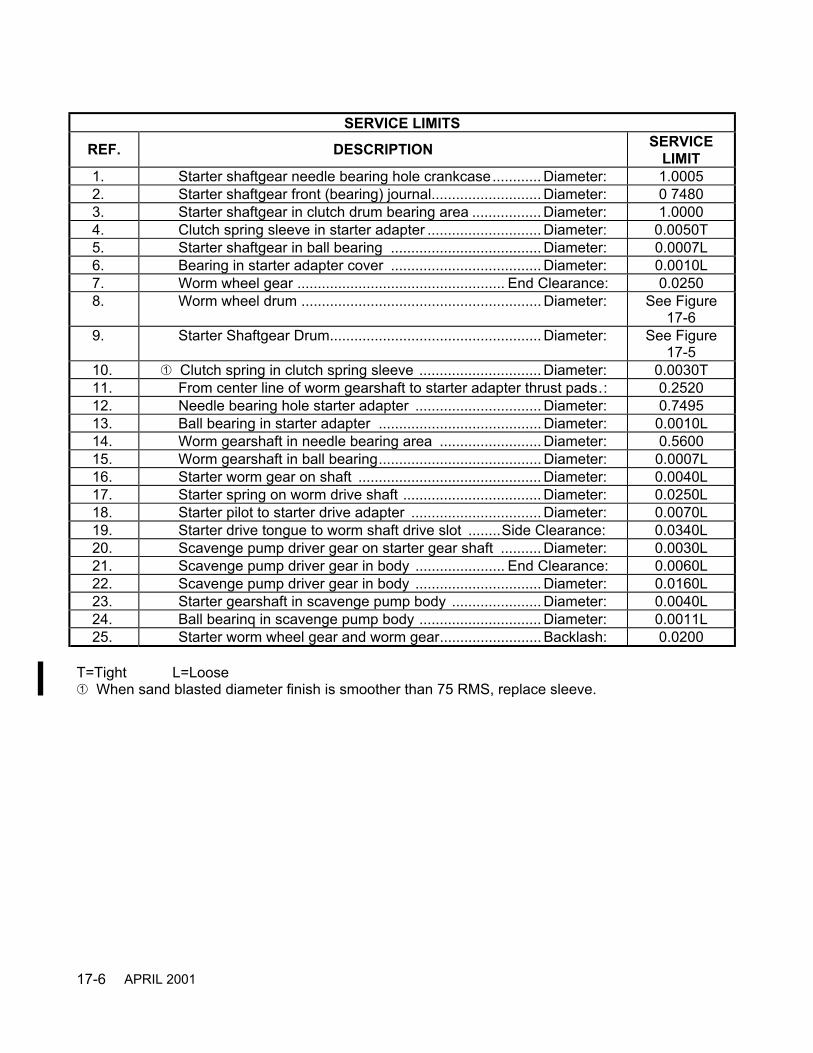
17-6
SERVICE LIMITS
REF. DESCRIPTION SERVICELIMIT
1. Starter shaftgear needle bearing hole crankcase............ Diameter: 1.00052. Starter shaftgear front (bearing) journal........................... Diameter: 0 74803. Starter shaftgear in clutch drum bearing area ................. Diameter: 1.00004. Clutch spring sleeve in starter adapter ............................ Diameter: 0.0050T5. Starter shaftgear in ball bearing ..................................... Diameter: 0.0007L6. Bearing in starter adapter cover ..................................... Diameter: 0.0010L7. Worm wheel gear ................................................... End Clearance: 0.02508. Worm wheel drum ........................................................... Diameter: See Figure
17-69. Starter Shaftgear Drum.................................................... Diameter: See Figure
17-510. Clutch spring in clutch spring sleeve .............................. Diameter: 0.0030T11. From center line of worm gearshaft to starter adapter thrust pads.: 0.252012. Needle bearing hole starter adapter ............................... Diameter: 0.749513. Ball bearing in starter adapter ........................................ Diameter: 0.0010L14. Worm gearshaft in needle bearing area ......................... Diameter: 0.560015. Worm gearshaft in ball bearing........................................ Diameter: 0.0007L16. Starter worm gear on shaft ............................................. Diameter: 0.0040L17. Starter spring on worm drive shaft .................................. Diameter: 0.0250L18. Starter pilot to starter drive adapter ................................ Diameter: 0.0070L19. Starter drive tongue to worm shaft drive slot ........Side Clearance: 0.0340L20. Scavenge pump driver gear on starter gear shaft .......... Diameter: 0.0030L21. Scavenge pump driver gear in body ...................... End Clearance: 0.0060L22. Scavenge pump driver gear in body ............................... Diameter: 0.0160L23. Starter gearshaft in scavenge pump body ...................... Diameter: 0.0040L24. Ball bearinq in scavenge pump body .............................. Diameter: 0.0011L25. Starter worm wheel gear and worm gear......................... Backlash: 0.0200
T=Tight L=Loose When sand blasted diameter finish is smoother than 75 RMS, replace sleeve.
APRIL 2001
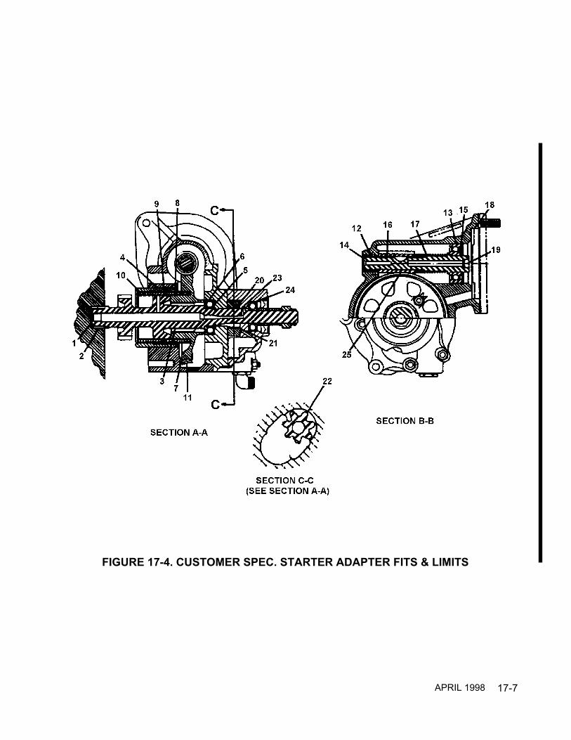
17-7
FIGURE 17-4. CUSTOMER SPEC. STARTER ADAPTER FITS & LIMITS
APRIL 1998
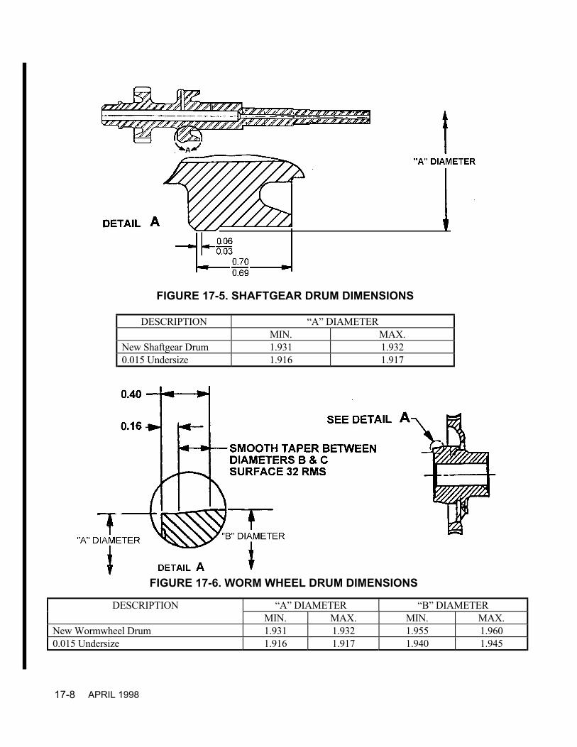
17-8
DESCRIPTION “A” DIAMETERMIN. MAX.
New Shaftgear Drum 1.931 1.9320.015 Undersize 1.916 1.917
DESCRIPTION “A” DIAMETER “B” DIAMETERMIN. MAX. MIN. MAX.
New Wormwheel Drum 1.931 1.932 1.955 1.9600.015 Undersize 1.916 1.917 1.940 1.945
FIGURE 17-5. SHAFTGEAR DRUM DIMENSIONS
FIGURE 17-6. WORM WHEEL DRUM DIMENSIONS
APRIL 1998
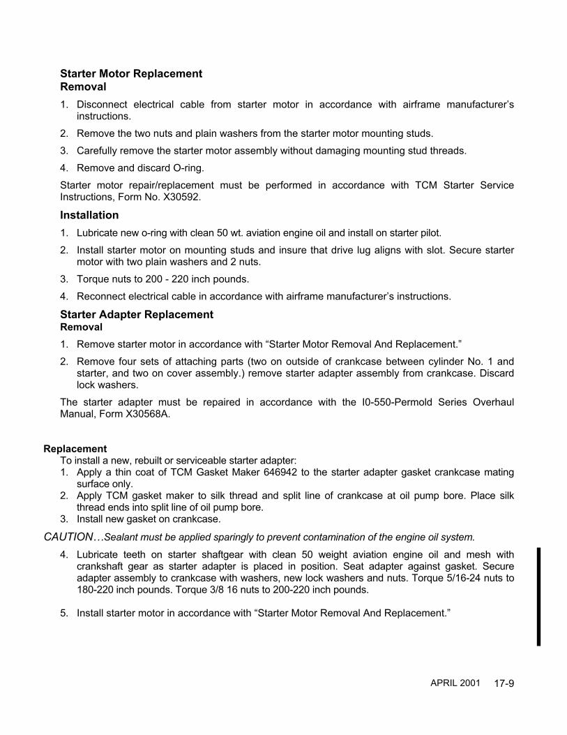
17-9
Starter Motor ReplacementRemoval1. Disconnect electrical cable from starter motor in accordance with airframe manufacturer’s
instructions.2. Remove the two nuts and plain washers from the starter motor mounting studs.3. Carefully remove the starter motor assembly without damaging mounting stud threads.4. Remove and discard O-ring.Starter motor repair/replacement must be performed in accordance with TCM Starter ServiceInstructions, Form No. X30592.
Installation1. Lubricate new o-ring with clean 50 wt. aviation engine oil and install on starter pilot.2. Install starter motor on mounting studs and insure that drive lug aligns with slot. Secure starter
motor with two plain washers and 2 nuts.3. Torque nuts to 200 - 220 inch pounds.4. Reconnect electrical cable in accordance with airframe manufacturer’s instructions.
Starter Adapter ReplacementRemoval1. Remove starter motor in accordance with “Starter Motor Removal And Replacement.”2. Remove four sets of attaching parts (two on outside of crankcase between cylinder No. 1 and
starter, and two on cover assembly.) remove starter adapter assembly from crankcase. Discardlock washers.
The starter adapter must be repaired in accordance with the I0-550-Permold Series OverhaulManual, Form X30568A.
ReplacementTo install a new, rebuilt or serviceable starter adapter:1. Apply a thin coat of TCM Gasket Maker 646942 to the starter adapter gasket crankcase mating
surface only.2. Apply TCM gasket maker to silk thread and split line of crankcase at oil pump bore. Place silk
thread ends into split line of oil pump bore.3. Install new gasket on crankcase.
CAUTION…Sealant must be applied sparingly to prevent contamination of the engine oil system.
4. Lubricate teeth on starter shaftgear with clean 50 weight aviation engine oil and mesh withcrankshaft gear as starter adapter is placed in position. Seat adapter against gasket. Secureadapter assembly to crankcase with washers, new lock washers and nuts. Torque 5/16-24 nuts to180-220 inch pounds. Torque 3/8 16 nuts to 200-220 inch pounds.
5. Install starter motor in accordance with “Starter Motor Removal And Replacement.”
APRIL 2001

17-10
INTENTIONALLY
LEFT
BLANK

18-1
CHAPTER 18
LUBRICATION SYSTEM
SECTION PAGE18-1 Lubrication System Description ............................. 18-218-2 Lubrication System Component
Detailed Description ............................................... 18-418-3 Lubrication System Maintenance .......................... 18-10
FIGURE PAGE18-1 Lubrication System Schematic .............................. 18-318-2 Oil Pump Description ............................................. 18-518-3 Oil Cooler And Oil Temperature Control
Valve Description.................................................... 18-718-4A Oil Sump And Suction Tube Description ................ 18-818-4B IO-550 Permold Oil Sumps..................................... 18-918-5 Stud Identification ................................................... 18-1018-6 Oil Filter Stud Inspection ........................................ 18-1118-7 Lubrication System Service Limits.......................... 18-14
APRIL 2001

18-2
18-1 LUBRICATION SYSTEM DESCRIPTIONThe engine oil supply is contained in the oil sump. The oil is drawn from the sump throughthe oil suction tube to the intake side of the engine driven, gear type, oil pump. From theoutlet side of the pump, oil is directed to the full flow, replaceable oil filter. A by-pass valve isincorporated in the oil filter. An oil pressure relief valve is incorporated in the oil pumphousing. The valve opens when the pump pressures exceed the adjusted limit and oil isdirected back to the intake side of the oil pump gears.From the oil filter discharge port, oil is directed through a crankcase passage to the oil cooler.In addition to facilities for oil cooling, the oil cooler incorporates an oil temperature controlvalve. Oil passing by the oil temperature control valve cavity directs oil either through the oilcooler core and or through the oil cooler by-pass to the crankcase passage at the reardepending on the oil temperature. If engine oil temperature is above 180°F, all oil is directedthrough the oil cooler.Oil entering the engine is directed to the hollow camshaft which serves as the engine main oilgallery. Grooves and drilled holes in the camshaft are located so as to afford properlubrication through a system of orifices to the main bearings, hydraulic valve tappets, idlergear bushing, accessory drive gear bushings and the starter drive gear bearing.Oil leaving the camshaft interior at the front of the crankcase is directed to the left maincrankcase gallery, from there it is directed upward through crankcase oil passages to themain thrust bearing and to the governor drive gear and accessory pad.
WARNINGOil pressure is applied to the face of the accessory drive pads. If gaskets,accessory or covers are not properly installed and hardware is not properlytorqued oil leakage will occur.From the governor drive gear lubricating oil is directed from the left main gallery through thepropeller governor to the drilled crankcase passages and oil transfer collar to the crankshaft.Oil then travels through a transfer plug installed in the inside diameter of the crankshaft andis routed to the variable pitch propeller. Hydraulic valve tappets transfer oil from the main oilgalleries to the cylinder overhead through the hollow pushrods to a drilled oil passage in therocker arms. Oil exiting the rocker arms lubricates the valve stems, springs and rotocoils.The oil then falls to the lower rocker cavity and returns to the crankcase and sump throughthe pushrod housings.Oil from the left main crankcase gallery is also directed upward through crankcase oilpassages to the crankshaft main bearings and idler gear bushing. Oil is directed upward fromthe idler gear bushing to both accessory drive bushings. Oil lubricating the crankshaft mainsis directed through the upper main bearing oil holes, through crankcase passages to oil squirtnozzles that spray oil onto the underside of the pistons for heat dissipation and lubrication.Oil falls from the pistons through the crankcase cavity back to the oil sump.
APRIL 1998
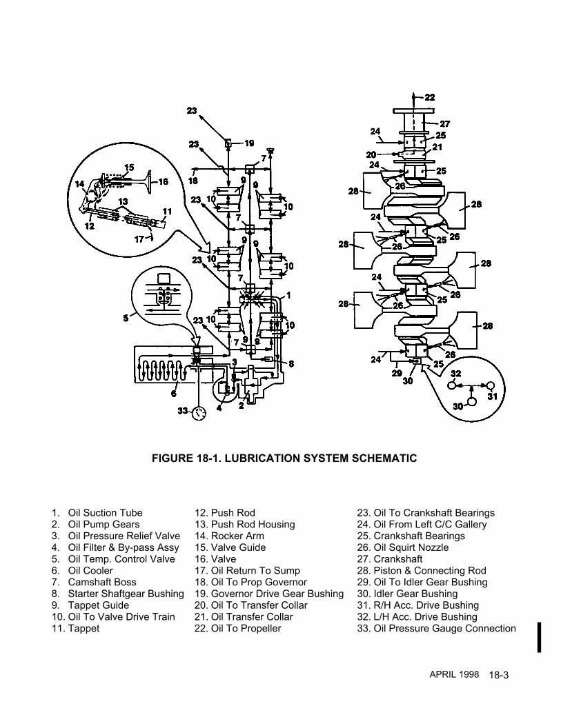
18-3
1. Oil Suction Tube 12. Push Rod 23. Oil To Crankshaft Bearings2. Oil Pump Gears 13. Push Rod Housing 24. Oil From Left C/C Gallery3. Oil Pressure Relief Valve 14. Rocker Arm 25. Crankshaft Bearings4. Oil Filter & By-pass Assy 15. Valve Guide 26. Oil Squirt Nozzle5. Oil Temp. Control Valve 16. Valve 27. Crankshaft6. Oil Cooler 17. Oil Return To Sump 28. Piston & Connecting Rod7. Camshaft Boss 18. Oil To Prop Governor 29. Oil To Idler Gear Bushing8. Starter Shaftgear Bushing 19. Governor Drive Gear Bushing 30. Idler Gear Bushing9. Tappet Guide 20. Oil To Transfer Collar 31. R/H Acc. Drive Bushing10. Oil To Valve Drive Train 21. Oil Transfer Collar 32. L/H Acc. Drive Bushing11. Tappet 22. Oil To Propeller 33. Oil Pressure Gauge Connection
FIGURE 18-1. LUBRICATION SYSTEM SCHEMATIC
APRIL 1998

18-4
18-2 LUBRICATION SYSTEM COMPONENT DETAILED DESCRIPTIONOil PumpThe positive displacement oil pump consists of two meshed gears that revolve inside thepump housing cavity. The clearance between the oil pump cavity and oil pump gear teeth issmall.The camshaft drives the oil pump drive gear, which drives the oil pump driven gear. The oilpump driven gear is supported by a shaft pressed into the oil pump housing.The oil pump drive gear shaft is supported by the tach drive housing on one end and the oilpump housing at the opposite end. The oil pump drive gear may have a tachometer drivegear attached to its end which drives a tachometer shaftgear inside the tach drive housing foreither electrical or mechanical tachometers.As the engine starts rotating, the oil pump drive gear turns (looking from the rear of theengine forward) counterclockwise, this drives the driven gear in a clockwise direction. Thetwo gears turning create a suction that draws oil from the sump, through the oil suction tubeto the pump gears. The oil is then forced around the outside of the gears and directedthrough a gallery to the oil filter adapter and pressure relief valve. Oil that flows past thepressure relief valve is directed through a passage back to the inlet side of the pump gears.The adjustable oil pressure relief valve maintains oil pressure to a preset value, this insuresadequate lubrication to the engine and its accessories at high engine RPM. Oil pressure isadjusted by turning the oil pressure relief valve adjusting screw.During normal operation oil flows from the by-pass to an area between the oil filter housingand filter element. The oil is then directed through the element and down to a gallery in thefilter adapter through a passage in the oil pump housing and out to the engine. The oil filterincorporates a by-pass in the event the filter element becomes clogged.
APRIL 1998

18-5
OIL FILTERELEMENT
OIL FILTERHOUSING
OIL PUMPHOUSING
OIL PUMPDRIVE GEAR
OIL PUMPDRIVEN GEAR
OIL SUCTIONTUBE PLUG
OIL FROMOIL SUMPOIL PRESSURE
RELIEF VALVE
RECIRCULATIONBACK TO INLET SIDE OF PUMP GEARS
OIL FLOWTO ENGINE
OIL FILTERADAPTER
FIGURE 18-2. OIL PUMP DESCRIPTION
APRIL 1998

18-6
18-2 LUBRICATION SYSTEM COMPONENT DETAILED DESCRIPTION (continued)Oil Cooler And Oil Temperature Control ValveOil flowing from the oil pump enters the oil cooler inlet where it is directed upward throughthe cooler core by the cast oil gallery. When the oil is below normal operating temperature,the oil temperature control valve (vernatherm) is open allowing oil to flow through the centerby-pass portion of the cooler. Oil flowing through the by-pass flows past the oil temperaturecontrol valve and out to the crankcase main oil galleries and camshaft.When oil temperature reaches 180°F the oil temperature control valve closes forcing the oilto flow through the oil cooler. As the oil flows through the cooler core cooling air fins betweenthe core oil passages dissipate excess heat from the oil maintaining normal operational oiltemperatures.
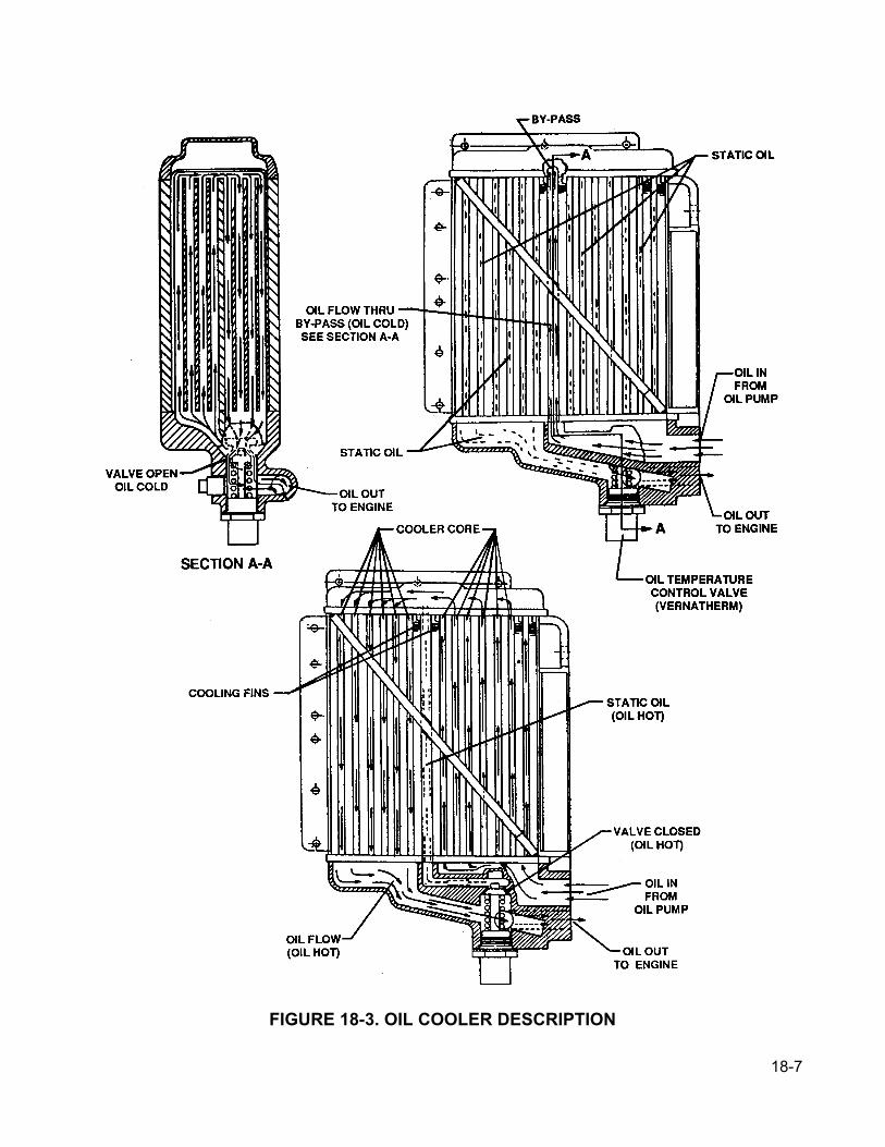
18-7
FIGURE 18-3. OIL COOLER DESCRIPTION

18-8
18-2 LUBRICATION SYSTEM COMPONENT DETAILED DESCRIPTION (continued)Oil SumpThe oil sump used on I0-550-A,C,G, N & P model engines is a stamp-pressed aluminumalloy assembly. The oil sump used on the I0-550-B & R model engines is cast aluminum withprovisions for attaching engine mount legs. The sump is held to the crankcase sump mountflange with 32 bolts, washers and lock washers. The oil sump assembly incorporates atapped drain plug boss, a plug and crush washer to facilitate draining of engine oil. The drainplug boss has provisions for safety wiring of the oil drain plug.
Oil Suction TubeThe oil suction tube extends from the oil sump to the oil pump inlet providing oil pick-up andflow path. The pick-up tube entrance is screened. On I0-550-A,C,G, N & P engines the pick-up end is supported by welded brackets bolted to the crankcase spine below the camshaft.On I0-550-B & R engines the pick-up end is supported by welded brackets bolted to twocrankcase bolt bosses. The opposite end with a crush washer installed protrudes through thecrankcase into the oil pump inlet. The threaded tube end is held and sealed to the oil pumphousing by a crush washer and a plug.
FIGURE 18-4A. OIL SUMP AND SUCTION TUBE DESCRIPTION
APRIL 2001

18-9
FIGURE 18-4B. IO-550 PERMOLD OIL SUMPS
APRIL 2001
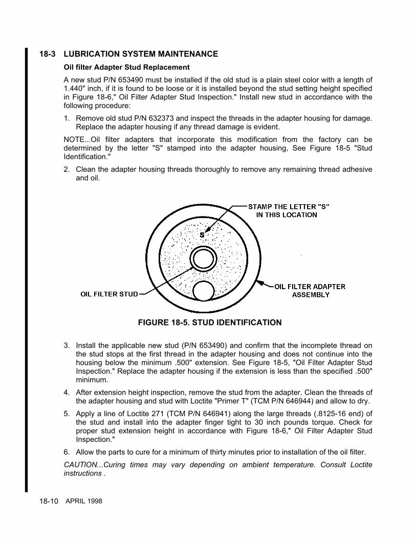
18-10
18-3 LUBRICATION SYSTEM MAINTENANCEOil filter Adapter Stud ReplacementA new stud P/N 653490 must be installed if the old stud is a plain steel color with a length of1.440" inch, if it is found to be loose or it is installed beyond the stud setting height specifiedin Figure 18-6," Oil Filter Adapter Stud Inspection." Install new stud in accordance with thefollowing procedure:1. Remove old stud P/N 632373 and inspect the threads in the adapter housing for damage.
Replace the adapter housing if any thread damage is evident.NOTE...Oil filter adapters that incorporate this modification from the factory can bedetermined by the letter "S" stamped into the adapter housing, See Figure 18-5 "StudIdentification."2. Clean the adapter housing threads thoroughly to remove any remaining thread adhesive
and oil.
3. Install the applicable new stud (P/N 653490) and confirm that the incomplete thread onthe stud stops at the first thread in the adapter housing and does not continue into thehousing below the minimum .500" extension. See Figure 18-5, "Oil Filter Adapter StudInspection." Replace the adapter housing if the extension is less than the specified .500"minimum.
4. After extension height inspection, remove the stud from the adapter. Clean the threads ofthe adapter housing and stud with Loctite "Primer T" (TCM P/N 646944) and allow to dry.
5. Apply a line of Loctite 271 (TCM P/N 646941) along the large threads (.8125-16 end) ofthe stud and install into the adapter finger tight to 30 inch pounds torque. Check forproper stud extension height in accordance with Figure 18-6," Oil Filter Adapter StudInspection."
6. Allow the parts to cure for a minimum of thirty minutes prior to installation of the oil filter.CAUTlON...Curing times may vary depending on ambient temperature. Consult Loctiteinstructions .
FIGURE 18-5. STUD IDENTIFICATION
APRIL 1998

18-11
After installation of a new oil filter adapter stud, stamp a .125" high letter "s" in the locationshown in Figure 18-5 Stud Identification
Oil PumpMalfunctioning oil pumps or oil pump components must be removed and discarded.The oil pump may be removed in accordance with oil pump disassembly/reassemblyinstructions in the IO-550 Permold Series Overhaul Manual, Form No. X30568A.Repairs other than smoothing nicks on parting surfaces, replacing studs and worn parts, andrefacing the oil pressure relief valve seat on the oil pump housing are not possible.The pump driven gear shaft is pressed into the pump housing and is not field replaceable.The pump gear chamber must not be enlarged. If it becomes scored, the pump housing mustbe discarded. Scoring on the gear contact area of the oil pump cover renders itunserviceable unless the parting surfaces can be lapped smooth and perfectly flat.If required, replace oil pump housing studs in accordance with the IO-550 Permold SeriesOverhaul Manual, Form X30568A.
Oil Filter AdapterDiscard oil filter adapters that are cracked or that are worn beyond specified limits. Smoothsmall nicks on parting surface. No other repairs are possible.
Oil SumpIf the oil sump must be removed for repair or replacement, see the I0-550 Permold SeriesOverhaul Manual, Form X30568A. Any airframe components that obstruct removal must beremoved in accordance with the airframe manufacturer’s instructions.Whenever the oil sump is removed, the oil suction tube screen must be cleaned and all lowerinternal hardware must be inspected for secure installation and safetying.
Discard any oil sump that is warped or cracked.
FIGURE 18-6. OIL FILTER ADAPTER STUD INSPECTION
APRIL 1998

18-12
Oil Suction TubeThe oil suction tube to oil pump housing plug gasket can be removed and replaced.To gain access to the oil suction tube assembly, the oil sump assembly must be removed.
Oil CoolerThe oil cooler or its components may be removed for replacement and repair in accordancewith applicable portions of oil cooler disassembly/reassembly instructions in the I0550Permold Series Overhaul Manual, Form X30568A.
Oil Pressure Relief ValveCut safety wire, remove the oil pressure relief valve and inspect the plunger for scoring,nicks, and the conical face for roughening. Oil pressure relief valves with scoring, nicks,roughening of the conical face or that exceed the specified limits must be discarded andreplaced with new. Inspect the oiI pressure relief valve seat for scoring, nicks or roughening.Seats with these indications must be refaced. Using the specified oil pressure relief spotfacer, reface the pressure relief valve seat in the oil pump housing.CAUTION... Reface pressure relief valve seat using light finger pressure when turningrefacing tool.
After the refacing procedure, the depth from the top of the oil pump housing to the seat facemust not exceed the specified limit item (2) in Figure 18-7," Lubrication System ServiceLimits. "Oil pump housings exceeding specified limits must be discarded.CAUTION... Thoroughly clean oil pressure relief valve cavity after refacing procedure. Alldebris from the refacing procedure must be removed.
Reassemble serviceable or new relief valve housing and adjusting screw. Turn adjustingscrew into housing about halfway. Install new copper washer and nut. Assemble plunger,spring, washer and slide into housing. Coat housing threads with TCM anti-seize lubricant.Insure relief valve components are aligned and install in oil pump housing. Torque housing to240-260 inch pounds. Safety wire oil pressure relief valve housing in accordance withchapter 9," Lockwire Procedure." The engine oil pressure must be adjusted prior to releasefor return to service in accordance with chapter 22, "Oil Pressure Adjustment."
Oil Temperature Control ValveRemove the oil temperature control valve and inspect the valve seat for scoring, nicks,roughness or deterioration. Oil temperature control valves exhibiting any of these indicationsor that exceed specified limits must be discarded and replaced with new. Reinstallserviceable or new oil temperature control valve using new gasket and torque to 440-460inch pounds for the small (639305) control valve and 640-660 inch pounds for the large(649369) control valve. Safety wire oil temperature control valve housing in accordance withchapter 9," Lockwire Procedure."
APRIL 1998
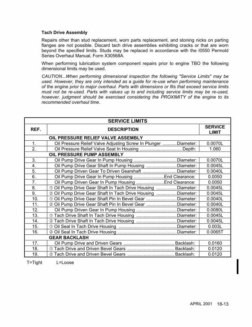
18-13
Tach Drive AssemblyRepairs other than stud replacement, worn parts replacement, and stoning nicks on partingflanges are not possible. Discard tach drive assemblies exhibiting cracks or that are wornbeyond the specified limits. Studs may be replaced in accordance with the I0550 PermoldSeries Overhaul Manual, Form X30568A.When performing lubrication system component repairs prior to engine TBO the followingdimensional limits may be used.CAUTION...When performing dimensional inspection the following "Service Limits" may beused. However, they are only intended as a guide for re-use when performing maintenanceof the engine prior to major overhaul. Parts with dimensions or fits that exceed service limitsmust not be re-used. Parts with values up to and including service limits may be re-used,however, judgment should be exercised considering the PROXIMITY of the engine to itsrecommended overhaul time.
SERVICE LIMITSREF. DESCRIPTION SERVICE
LIMITOIL PRESSURE RELIEF VALVE ASSEMBLY
1. Oil Pressure Relief Valve Adjusting Screw In Plunger ...........Diameter: 0.0070L2. Oil Pressure Relief Valve Seat In Housing ................................. Depth: 1.060
OIL PRESSURE PUMP ASSEMBLY3. Oil Pump Drive Gear In Pump Housing ..................................Diameter: 0.0070L4. Oil Pump Drive Gear Shaft In Pump Housing ........................Diameter: 0.0045L5. Oil Pump Driven Gear To Driven Gearshaft ...........................Diameter: 0.0040L6. Oil Pump Drive Gear In Pump Housing ........................End Clearance: 0.00507. Oil Pump Driven Gear In Pump Housing ......................End Clearance: 0.00508. Oil Pump Drive Gear Shaft In Tach Drive Housing ................Diameter: 0.0045L9. Oil Pump Drive Gear Shaft In Tach Drive Housing ................Diameter: 0.0045L10. Oil Pump Drive Gear Shaft Pin In Bevel Gear ........................Diameter: 0.0040L11. Oil Pump Drive Gear Shaft Pin In Bevel Gear ........................Diameter: 0.0040L12. Oil Pump Driven Gear In Pump Housing ................................Diameter: 0.0080L13. Tach Drive Shaft In Tach Drive Housing ................................Diameter: 0.0045L14. Tach Drive Shaft In Tach Drive Housing ................................Diameter: 0.0045L15. Oil Seal In Tach Drive Housing ..............................................Diameter: 0.003L16. Oil Seal In Tach Drive Housing ...............................................Diameter: 0.0065T
GEAR BACKLASH17. Oil Pump Drive and Driven Gears ........................................ Backlash: 0.016018. Tach Drive and Driven Bevel Gears ..................................... Backlash: 0.012019. Tach Drive and Driven Bevel Gears ..................................... Backlash: 0.0120
T=Tight L=Loose
APRIL 2001

18-14
REF. DESCRIPTION SERVICELIMIT
SPRING TEST DATA20. Oil Pressure Relief Valve Spring
Compressed To 1.25 Inch Length ............................................ Load: 30 Lbs.21.
(639305Valve)
Oil temperature control valve0.090 inches minimum travel at ...................................Oil Temperature:
120°-170°
Oil temperature control valve must close between .......Oil Temperature: 168°-172°21.
(649369Valve)
Oil temperature control valve0.160 inches minimum travel at ...................................Oil Temperature: 135°-175°Oil temperature control valve must close between .......Oil Temperature: 171-175°
Mechanical Tach Drive Electrical Tach Drive
FIGURE 18-7. LUBRICATION SYSTEM SERVICE LIMITS
APRIL 2001

18-15
INTENTIONALLY
LEFT
BLANK

19-1
CHAPTER 19
CYLINDER ASSEMBLY
SECTION PAGE19-1 Cylinder Cooling.......................................................... 19-219-2 Cylinders, Pistons And Overhead Drive Train............ 19-319-3 Cylinder Assembly Detailed Description .................... 19-419-4 Cylinder Assembly Maintenance ................................ 19-10
FIGURE PAGE19-1 General Engine Cooling Airflow Diagram................... 19-219-2 Cylinder Piston And Overhead Drive Train................. 19-319-3 Cylinder Assembly Description IO-550-A,B&C........... 19-419-4 Cylinder Assembly Description IO-550-G, N. P & R... 19-519-5 Piston Assembly Description ...................................... 19-619-6 Overhead Drive Train Description IO-550-A,B&C...... 19-719-7 Overhead Drive Train Description
IO-550-G, N, P & R ..................................................... 19-819-8 Hydraulic Tappet Description...................................... 19-919-9 Master Orifice Tool...................................................... 19-1219-10 Static Seal ................................................................... 19-1319-11 Dynamic Seal .............................................................. 19-1319-12 Differential Pressure Tester Calibration...................... 19-1419-13 Ring Positioning .......................................................... 19-1619-14 Light Rust Formation, Hone Not Affected................... 19-1819-15 Heavy Rust Formation, Surface Pitting Has Altered
Honed Pattern............................................................. 19-1919-16 New Steel Cylinder Bore............................................. 19-2019-17 Typical Cylinder Bore At TBO..................................... 19-2019-18 Heavily Worn Cylinder Bore........................................ 19-2119-19 Baffle Seals Improperly Positioned............................. 19-2519-20 Baffle Seals Not Sealing Properly............................... 19-2619-21 Baffles With Air Gaps.................................................. 19-2719-22 Gaps In Baffle Seal ..................................................... 19-2819-23 Torque Sequence For Single Cylinder ....................... 19-3419-24 Cylinder Assembly Service Limits IO-550-A,B&C ...... 19-3719-25 Cylinder Dimensions IO-550-A,B&C........................... 19-3819-26 Cylinder Assembly Service Limits
I0-550-G, N, P & R...................................................... 19-4119-27 Cylinder Dimensions IO-550-G, N, P & R.................. 19-42
APRIL 2001

19-2
19-1 CYLINDER COOLINGCylinder cooling is accomplished by transferring heat from the cylinder barrel and head coolingfins to the surrounding airflow. Airframe engine cowling and engine/airframe supplied bafflesand baffle seals direct cooling airflow close and evenly around the cylinders. Controlling airflowin this manner contributes to uniform cylinder temperatures. Cooling airflow is generated by airfrom the propeller and ram air induced by the aircraft's forward movement. This airflow isregulated by the size of the cooling air inlets and outlets. Increasing or decreasing outlet sizewith the use of airframe cowl flaps changes airflow and is used as an aid in controlling engineoperating temperatures. Below is a general illustration showing engine cooling airflow.
HIGH PRESSUREAREA
LOW PRESSUREAREA
AIRCRAFT SUPPLIEDCOOLING BAFFLES
COWL FLAPS
RAMAIR
RAMAIR
COOLINGAIR
EXIT
FIGURE 19-1. GENERAL ENGINE COOLING AIRFLOW DIAGRAM
APRIL 2001

19-3
19-2 CYLINDERS, PISTONS AND OVERHEAD DRIVE TRAINThe cylinders, pistons and overhead drive train are the portion of the engine that developpower. The cylinder combustion chamber provides a controlled area for burning fuel/air mixtureand converting that heat energy into mechanical energy. Aviation fuel and air is drawn into acylinder during the intake stroke, compressed by the piston during the compression stroke andthen ignited by a high intensity spark produced across the spark plug electrode air gap duringthe power stroke. As the mixture is ignited, the expanding gases force the piston to moveinward toward the crankshaft.This inward motion acting on the connecting rod and crankshaft throw is converted into circularor rotary motion by the crankshaft. As the crankshaft throw rotates past half of one revolution,the connecting rod and piston start moving outward on the exhaust stroke toward the cylinderhead. During this movement, the exhaust valve begins to open allowing the burned mixture(exhaust) to escape. Momentum from the crankshaft forces the piston toward the cylinder headin preparation of the next intake stroke event.Proper mechanical timing between the crankshaft and camshaft allows the intake and exhaustvalves to open and close in synchronization with piston position in all six cylinders.Proper magneto internal timing and magneto to engine mechanical timing allow precise sparkplug ignition, 22°±1° before top dead center, during the piston's compression stroke.
CAMSHAFT
ROCKER ARM
CYLINDER HEADAND BARREL
PISTON& RINGS
CONNECTINGROD
PUSHROD
VALVES
CRANKSHAFT
HYDRAULICTAPPET
FIGURE 19-2. CYLINDER, PISTON AND OVERHEAD DRIVE TRAIN
APRIL 2001

19-4
19-3 CYLINDER ASSEMBLY DETAILED DESCRIPTION IO-550-A, B & CCylinder, Valve Guides, Valves, Rotocoil And Retainer - The externally finned aluminum alloyhead castings are heated and valve seat inserts installed before the head is screwed andshrunk onto an externally finned steel alloy barrel to make the permanent head and barrelassembly. The cylinder barrel is nitrided for wear resistance. Intake and exhaust valve guidesare pressed into the heated cylinder assembly. Special helical coil thread inserts are installed inupper and lower spark plug holes. The cylinder intake and exhaust ports are located below thecylinder as installed. Valve stems are solid. A rotocoil assembly retains the two concentricsprings surrounding the exhaust valve and is locked to the exhaust valve stem by tapered,semi-circular keys which engage grooves around the stem. The controlled rotating action of thistype retainer helps to prevent burning and eroding of the valve and valve seat. A retainerretains the two concentric springs surrounding the intake valve and is locked to the intake valvestem by tapered, semi-circular keys which engage grooves around the stem. Valve rockercovers are painted diecast aluminum .
FIGURE 19-3. CYLINDER ASSEMBLY DESCRIPTION IO-550-A,B & C
APRIL 1998

19-5
19-3 CYLINDER ASSEMBLY DETAILED DESCRIPTION IO-550-G, N, P & RCylinder, Valve Guides, Valves, Rotocoil And Retainer - The externally finned aluminum alloyhead castings are heated and valve seat inserts installed before the head is screwed andshrunk onto an externally finned steel alloy barrel to make the permanent head and barrelassembly. The cylinder barrel is nitrided for wear resistance. Intake and exhaust valve guidesare pressed into the heated cylinder assembly. Special helical coil thread inserts are installed inupper and lower spark plug holes. The cylinder intake ports are located on the top of thecylinder and exhaust ports are located below the cylinder as installed. Valve stems are solid. Arotocoil assembly retains the two concentric springs surrounding the exhaust valve and islocked to the exhaust valve stem by tapered, semi-circular keys which engage grooves aroundthe stem. The controlled rotating action of this type retainer helps to prevent burning anderoding of the valve and valve seat. A retainer retains the two concentric springs surroundingthe intake valve and is locked to the intake valve stem by tapered, semi-circular keys whichengage grooves around the stem. Valve rocker covers are stamped sheet metal and use twoper cylinder.
FIGURE 19-4. CYLINDER ASSEMBLY DESCRIPTION IO-550-G, N, P & R
APRIL 2001
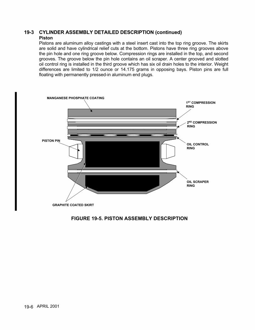
19-6
19-3 CYLINDER ASSEMBLY DETAILED DESCRIPTION (continued)PistonPistons are aluminum alloy castings with a steel insert cast into the top ring groove. The skirtsare solid and have cylindrical relief cuts at the bottom. Pistons have three ring grooves abovethe pin hole and one ring groove below. Compression rings are installed in the top, and secondgrooves. The groove below the pin hole contains an oil scraper. A center grooved and slottedoil control ring is installed in the third groove which has six oil drain holes to the interior. Weightdifferences are limited to 1/2 ounce or 14.175 grams in opposing bays. Piston pins are fullfloating with permanently pressed-in aluminum end plugs.
PISTON PIN
MANGANESE PHOSPHATE COATING
GRAPHITE COATED SKIRT
1ST COMPRESSIONRING
2ND COMPRESSIONRING
OIL CONTROLRING
OIL SCRAPERRING
FIGURE 19-5. PISTON ASSEMBLY DESCRIPTION
APRIL 2001

19-7
19-3 CYLINDER ASSEMBLY DETAILED DESCRIPTION (continued)Valve Rockers, Shafts, Pushrods And Housings (Overhead Drive Train) I0-550-A, B & CValve rockers are steel forgings with hardened sockets, rocker faces and pressed in bronzebushings. They have a drilled oil passage for lubrication. The rocker shafts are held in place inthe rocker bosses by bolts and washers. Pushrods are constructed of steel tubes andpressed-in, hardened, forged steel ball ends, which are center drilled for oil passages. Thepushrod housings are beaded steel tubes. The bead at the cylinder end retains washer, gasketand a second washer. The bead at the crankcase end retains a heavy spring, washer, packingring and second washer.
FIGURE 19-6. OVERHEAD DRIVE TRAIN DESCRIPTION IO-550-A,B & C
APRIL 1998

19-8
19-3 CYLINDER ASSEMBLY DETAILED DESCRIPTION (continued)Valve Rockers, Shafts, Pushrods And Housings (Overhead Drive Train) I0-550-G, N, P & RValve rockers are steel forgings with hardened sockets, rocker faces and pressed in bronzebushings. They have a drilled oil passage for lubrication. The rocker shafts are held in place onthe rocker bosses by retainers, locking tab washers and bolts. Pushrods are constructed ofsteel tubes and pressed-in, hardened, forged steel ball ends, which are center drilled for oilpassages. The pushrod housings are beaded steel tubes. The bead at the cylinder end retainsa gasket. The bead at the crankcase end retains a heavy spring, washer, packing ring andsecond washer.
FIGURE 19-7. OVERHEAD DRIVE TRAIN DESCRIPTION IO-550-G, N, P & R
APRIL 2001
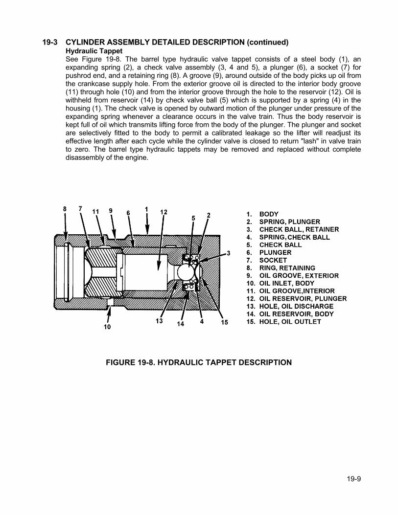
19-9
19-3 CYLINDER ASSEMBLY DETAILED DESCRIPTION (continued)Hydraulic TappetSee Figure 19-8. The barrel type hydraulic valve tappet consists of a steel body (1), anexpanding spring (2), a check valve assembly (3, 4 and 5), a plunger (6), a socket (7) forpushrod end, and a retaining ring (8). A groove (9), around outside of the body picks up oil fromthe crankcase supply hole. From the exterior groove oil is directed to the interior body groove(11) through hole (10) and from the interior groove through the hole to the reservoir (12). Oil iswithheld from reservoir (14) by check valve ball (5) which is supported by a spring (4) in thehousing (1). The check valve is opened by outward motion of the plunger under pressure of theexpanding spring whenever a clearance occurs in the valve train. Thus the body reservoir iskept full of oil which transmits lifting force from the body of the plunger. The plunger and socketare selectively fitted to the body to permit a calibrated leakage so the lifter will readjust itseffective length after each cycle while the cylinder valve is closed to return "lash" in valve trainto zero. The barrel type hydraulic tappets may be removed and replaced without completedisassembly of the engine.
FIGURE 19-8. HYDRAULIC TAPPET DESCRIPTION

19-10
19-4 CYLINDER ASSEMBLY MAINTENANCE
OWNER/OPERATOR OPERATIONAL AWARENESSThe aircraft operator can significantly influence the service life of the cylinders and othercomponents by an increased awareness of engine requirements. Example: Rust prevention byfrequent operation or by following recommended preservation procedures if the aircraft is inactive.
Using the correct type and grade engine oil and requiring frequent oil changes are important areaswhere an informed owner/operator can extend engine life. In general, becoming knowledgeableabout all of your aircraft's maintenance requirements will help you make informed decisions.Membership in TCM LINK Aviator Services provides an outstanding means of obtaining informationand recommendations for operation and maintenance of your engine. For more information aboutTCMLINK visit www.TCMLINK.com online.
The life of cylinders and cylinder components is highly dependent on correct operatingtemperatures. Control of operating temperatures is a function of installation design andmaintenance, and operator control of fuel flow and cowl flaps. During high power and slow speedaircraft operations, the fuel/air mixture must be rich to supplement air cooling. Enriched fuel flow is apowerful way of controlling combustion temperatures and, therefore, cylinder, piston, and ringtemperatures.
The highest combustion temperatures occur near the ideal fuel/air ratio of about one pound of fuelfor 15 pounds of air. Combustion temperatures drop on both the lean side and rich side of this point.However, on the lean side of peak, the reduction in power with leaning is rapid and lean misfireoccurs on many engines about 100 degrees F lean of peak. On the rich side, power is very stablewith changes in fuel flow. This characteristic allows the engine to obtain rated power with richmixtures where the combustion temperatures are substantially reduced. This additional fuel attakeoff is required to maintain control of cylinder structure and oil cooling.
In cruise, operating rich reduces combustion temperatures and should be used to control enginetemperatures. For maximum range, operation on the lean side of peak or at peak is permitted at lowcruise power on some engine models. For normal operation, it is good practice that mixtures becontrolled so that the hot cylinder is 50 to 100 degrees F rich of peak at cruise settings.
In addition, rapid temperature changes should be avoided. Warm-up and cool down periods at thestart and end of flights are also recommended. Leaning recommendations and fuel flow limits arefound in the Airplane Flight Manual, or supplemental Airplane Flight Manual if you have an STCinstallation. These recommendations should be followed with pilot control of fuel flows and cowlflaps used to maintain temperature control.
APRIL 2001

19-11
The following information on cylinder inspection should be performed during regularly scheduledinspection and annually as part of a regularly scheduled inspection to identify cylinder condition andinstallation items which can result in reduced cylinder life.The points of the following inspection are:• Cylinder Differential Compression Check And Trend Monitoring• Cylinder Borescope Inspection, As Required• Oil Consumption Trend Monitoring• Oil Analysis Trend Monitoring• Baffle Condition Inspection• Induction System Examination• Cowling Inspection And Cowl Flap Operational Check• Ignition System Inspection• Fuel System Setup• Verification Of Accuracy Of Engine Gages
Minimum Tool Requirements For Performing The Cylinder Inspection:• Basic Mechanic's Hand Tools• Calibrated Torque Wrench• Inspection Light and Mirror• Calibrated Differential Compression Tester• Master Orifice Tool, P/N 646953• Borescope• Magneto Timing Light, Protractor and TDC Plug• Calibrated Fuel System Adjustment Gages• Tachometer Tester• CHT / EGT Tester
CYLINDER DIFFERENTIAL COMPRESSION CHECKWearing of cylinder walls, ring surfaces, and valve seats occur throughout the life of an engine. Atregular maintenance or when condition inspections are indicated, the following differentialcompression check should be made and recorded for trend monitoring.It is important to note that differential compression checks are used to identify cylinder leakage ratesand the source of the leakage. This check cannot be directly related to engine horsepower. ENGINETESTING HAS SHOWN THAT CERTIFICATION HORSEPOWER RATINGS WILL CONTINUE TOBE DELIVERED EVEN WHEN ALL CYLINDERS ARE AT OR BELOW THE MINIMUMALLOWABLE CALIBRATED COMPRESSION READING AS ESTABLISHED BY THE MASTERORIFICE TOOL.
APRIL 2001
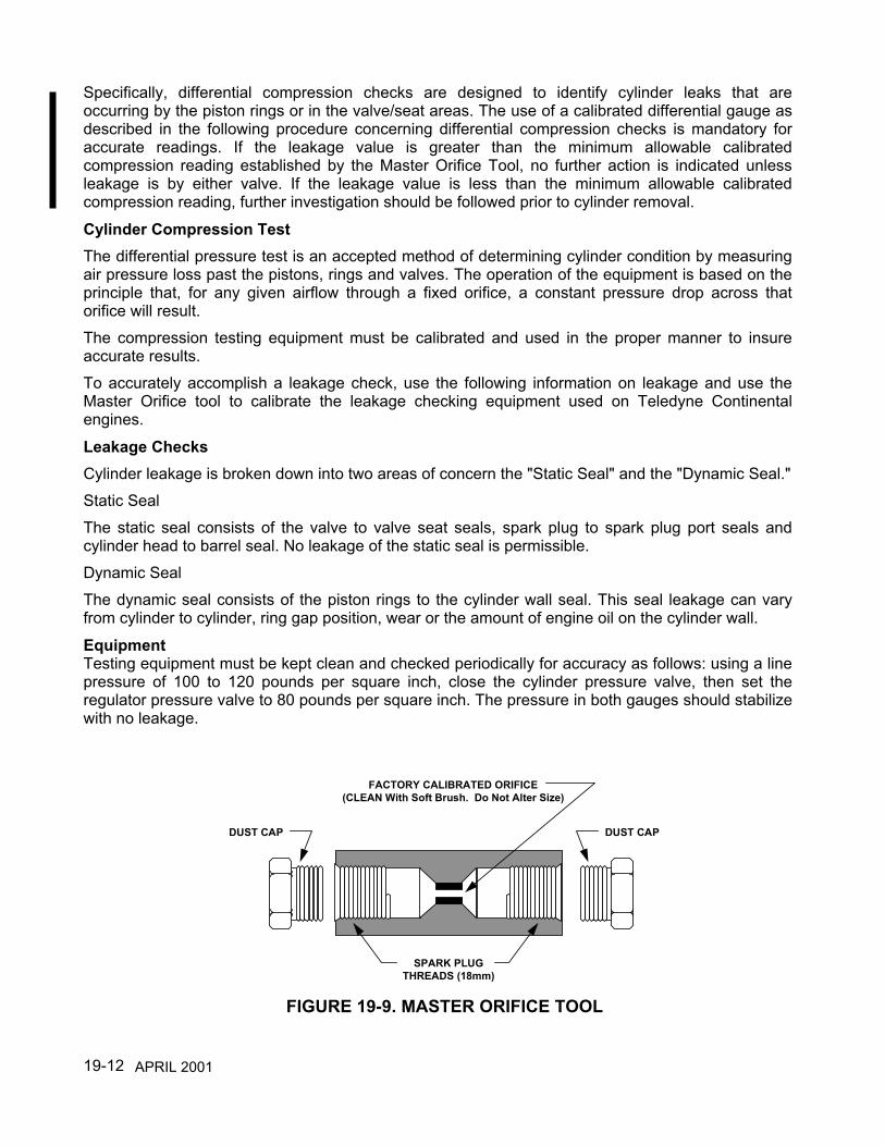
19-12
Specifically, differential compression checks are designed to identify cylinder leaks that areoccurring by the piston rings or in the valve/seat areas. The use of a calibrated differential gauge asdescribed in the following procedure concerning differential compression checks is mandatory foraccurate readings. If the leakage value is greater than the minimum allowable calibratedcompression reading established by the Master Orifice Tool, no further action is indicated unlessleakage is by either valve. If the leakage value is less than the minimum allowable calibratedcompression reading, further investigation should be followed prior to cylinder removal.
Cylinder Compression TestThe differential pressure test is an accepted method of determining cylinder condition by measuringair pressure loss past the pistons, rings and valves. The operation of the equipment is based on theprinciple that, for any given airflow through a fixed orifice, a constant pressure drop across thatorifice will result.The compression testing equipment must be calibrated and used in the proper manner to insureaccurate results.To accurately accomplish a leakage check, use the following information on leakage and use theMaster Orifice tool to calibrate the leakage checking equipment used on Teledyne Continentalengines.
Leakage ChecksCylinder leakage is broken down into two areas of concern the "Static Seal" and the "Dynamic Seal."Static SealThe static seal consists of the valve to valve seat seals, spark plug to spark plug port seals andcylinder head to barrel seal. No leakage of the static seal is permissible.Dynamic SealThe dynamic seal consists of the piston rings to the cylinder wall seal. This seal leakage can varyfrom cylinder to cylinder, ring gap position, wear or the amount of engine oil on the cylinder wall.
EquipmentTesting equipment must be kept clean and checked periodically for accuracy as follows: using a linepressure of 100 to 120 pounds per square inch, close the cylinder pressure valve, then set theregulator pressure valve to 80 pounds per square inch. The pressure in both gauges should stabilizewith no leakage.
FACTORY CALIBRATED ORIFICE(CLEAN With Soft Brush. Do Not Alter Size)
SPARK PLUGTHREADS (18mm)
DUST CAP DUST CAP
FIGURE 19-9. MASTER ORIFICE TOOL
APRIL 2001
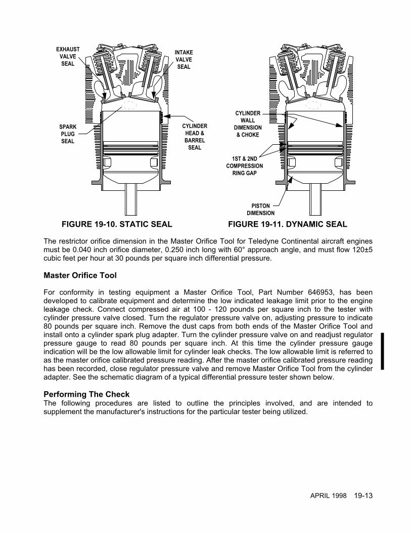
19-13
The restrictor orifice dimension in the Master Orifice Tool for Teledyne Continental aircraft enginesmust be 0.040 inch orifice diameter, 0.250 inch long with 60° approach angle, and must flow 120±5cubic feet per hour at 30 pounds per square inch differential pressure.
Master Orifice Tool
For conformity in testing equipment a Master Orifice Tool, Part Number 646953, has beendeveloped to calibrate equipment and determine the low indicated leakage limit prior to the engineleakage check. Connect compressed air at 100 - 120 pounds per square inch to the tester withcylinder pressure valve closed. Turn the regulator pressure valve on, adjusting pressure to indicate80 pounds per square inch. Remove the dust caps from both ends of the Master Orifice Tool andinstall onto a cylinder spark plug adapter. Turn the cylinder pressure valve on and readjust regulatorpressure gauge to read 80 pounds per square inch. At this time the cylinder pressure gaugeindication will be the low allowable limit for cylinder leak checks. The low allowable limit is referred toas the master orifice calibrated pressure reading. After the master orifice calibrated pressure readinghas been recorded, close regulator pressure valve and remove Master Orifice Tool from the cylinderadapter. See the schematic diagram of a typical differential pressure tester shown below.
Performing The CheckThe following procedures are listed to outline the principles involved, and are intended tosupplement the manufacturer's instructions for the particular tester being utilized.
EXHAUSTVALVESEAL
INTAKEVALVESEAL
SPARKPLUGSEAL
CYLINDERHEAD &BARREL
SEAL
CYLINDERWALL
DIMENSION& CHOKE
PISTONDIMENSION
1ST & 2NDCOMPRESSION
RING GAP
FIGURE 19-10. STATIC SEAL FIGURE 19-11. DYNAMIC SEAL
APRIL 1998

19-14
WARNINGTo prevent possibility of serious bodily injury or death, before moving thepropeller accomplish the following:a. Disconnect all spark plug leads.b. Verify magneto switches are connected to magnetos, that they are in the "OFF"
Position and "P" leads are grounded.c. Throttle position "CLOSED."d. Mixture control "IDLE-CUT-OFF."e. Set brakes and block aircraft wheels.f. Insure that aircraft tie-downs are installed and verify that the cabin door latch
is open.g. Do not stand within the arc of the propeller blades while turning the propeller.
(1) Perform the test as soon as possible after the engine is shut down to insure that the piston rings,cylinder walls, and other engine parts are well lubricated and at operating conditions.
(2) Turn the crankshaft by hand in the direction of rotation until the piston, in the cylinder beingchecked, is coming up on its compression stroke.
CYLINDERPRESSURE
GAUGE
RESTRICTORORIFICE
REGULATORPRESSURE
VALVE
COMPRESSEDAIR SOURCE
CYLINDERPRESSURE
VALVE
CYLINDERADAPTER
CYLINDER
REGULATORPRESSUREGAUGE
CYLINDERPRESSURE
GAUGE
RESTRICTORORIFICE
REGULATORPRESSURE
VALVE
COMPRESSEDAIR SOURCE
CYLINDERPRESSURE
VALVE
REGULATORPRESSUREGAUGE
���������������������������������������������������������������������������
CYLINDERADAPTER
MASTER ORIFICE(HAND TIGHT)
FIGURE 19-12. DIFFERENTIAL PRESSURE TESTER CALIBRATION
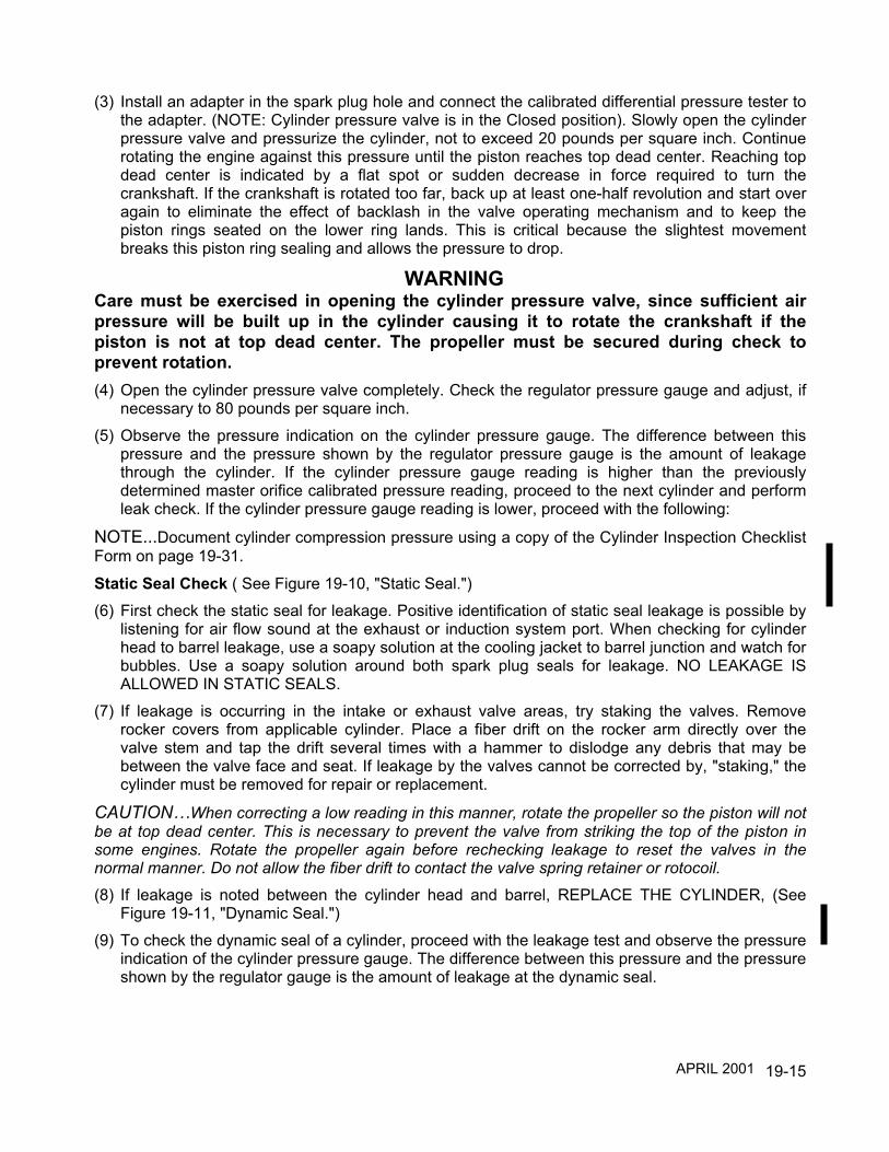
19-15
(3) Install an adapter in the spark plug hole and connect the calibrated differential pressure tester tothe adapter. (NOTE: Cylinder pressure valve is in the Closed position). Slowly open the cylinderpressure valve and pressurize the cylinder, not to exceed 20 pounds per square inch. Continuerotating the engine against this pressure until the piston reaches top dead center. Reaching topdead center is indicated by a flat spot or sudden decrease in force required to turn thecrankshaft. If the crankshaft is rotated too far, back up at least one-half revolution and start overagain to eliminate the effect of backlash in the valve operating mechanism and to keep thepiston rings seated on the lower ring lands. This is critical because the slightest movementbreaks this piston ring sealing and allows the pressure to drop.
WARNINGCare must be exercised in opening the cylinder pressure valve, since sufficient airpressure will be built up in the cylinder causing it to rotate the crankshaft if thepiston is not at top dead center. The propeller must be secured during check toprevent rotation.(4) Open the cylinder pressure valve completely. Check the regulator pressure gauge and adjust, if
necessary to 80 pounds per square inch.(5) Observe the pressure indication on the cylinder pressure gauge. The difference between this
pressure and the pressure shown by the regulator pressure gauge is the amount of leakagethrough the cylinder. If the cylinder pressure gauge reading is higher than the previouslydetermined master orifice calibrated pressure reading, proceed to the next cylinder and performleak check. If the cylinder pressure gauge reading is lower, proceed with the following:
NOTE...Document cylinder compression pressure using a copy of the Cylinder Inspection ChecklistForm on page 19-31.
Static Seal Check ( See Figure 19-10, "Static Seal.")(6) First check the static seal for leakage. Positive identification of static seal leakage is possible by
listening for air flow sound at the exhaust or induction system port. When checking for cylinderhead to barrel leakage, use a soapy solution at the cooling jacket to barrel junction and watch forbubbles. Use a soapy solution around both spark plug seals for leakage. NO LEAKAGE ISALLOWED IN STATIC SEALS.
(7) If leakage is occurring in the intake or exhaust valve areas, try staking the valves. Removerocker covers from applicable cylinder. Place a fiber drift on the rocker arm directly over thevalve stem and tap the drift several times with a hammer to dislodge any debris that may bebetween the valve face and seat. If leakage by the valves cannot be corrected by, "staking," thecylinder must be removed for repair or replacement.
CAUTION…When correcting a low reading in this manner, rotate the propeller so the piston will notbe at top dead center. This is necessary to prevent the valve from striking the top of the piston insome engines. Rotate the propeller again before rechecking leakage to reset the valves in thenormal manner. Do not allow the fiber drift to contact the valve spring retainer or rotocoil.
(8) If leakage is noted between the cylinder head and barrel, REPLACE THE CYLINDER, (SeeFigure 19-11, "Dynamic Seal.")
(9) To check the dynamic seal of a cylinder, proceed with the leakage test and observe the pressureindication of the cylinder pressure gauge. The difference between this pressure and the pressureshown by the regulator gauge is the amount of leakage at the dynamic seal.
APRIL 2001

19-16
WARNINGTo prevent possibility of serious bodily injury or death, before moving thepropeller accomplish the following:a. Disconnect all spark plug leads .b. Verify magneto switches are connected to magnetos, that they are in the "OFF"
Position and "P" leads are grounded .c. Throttle position "CLOSED."d. Mixture control "IDLE-CUT-OFF."e. Set brakes and block aircraft wheels. Insure that aircraft tie-downs are installed
and verify that the cabin door latch is open.f. Do not stand within the arc of the propeller blades while turning the propeller.
(10) If the leakage is below the previously determined low cylinder gauge reading, loss past thedynamic seal may be due to piston ring end gap alignment or by the piston and piston ringsangular direction in the cylinder bore See Figure 19-13, "Ring Positioning." First insure that thepiston and piston rings are centered. This can be accomplished by reducing regulator pressureto 20 pounds per square inch and working piston through top dead center several times bringingthe piston to top dead center in the normal direction of engine rotation. Adjust regulated pressureto 80 pounds per square inch and determine amount of loss. If the gauge reading is higher thanthe previously determined master orifice calibrated reading, proceed to next cylinder to betested.
NOTE...Piston ring rotation within the ring land is a normal design characteristic. As illustrated inFigure 19-13, "Ring Positioning," the compression ring location may have a direct bearing on thedynamic seal pressure check. Therefore, complete the test in the opposite direction if readings arebelow prescribed limits.(11) If recheck of cylinder pressure gauge reading indication remains below allowable loss, engine
may be run up to operating temperature and rechecked prior to cylinder being removed andrepaired. Rework of cylinders must be accomplished in accordance with "Cylinder AssemblyRepair And Replacement" in the I0-550 Permold Series Overhaul Manual, Form X30568A.
TOP COMPRESSIONRING GAP
T.D.C.
DIRECTIONOF
MOVEMENT
T.D.C.
DIRECTIONOF
MOVEMENT
TOP COMPRESSIONRING GAP
FIGURE 19-13. RING POSITIONINGAPRIL 2001

19-17
After cylinder compression test, if all cylinders are within specifications reinstall spark plugs andtorque to 300-360 inch pounds.
Compression Test TroubleshootingUse the following troubleshooting chart as a guide. Review the probable causes and other listings ofproblems that have similar symptoms. The probable causes are listed in order of “easiest to find”which is not necessarily in order of probability of occurrence.
First Check Check For Method DiscrepancyCorrective
Action
Static seal(No leakagePermissible)
Intake valve to seat seal Listen to air flowin intake port
CarbonCracked cylinderSeat worn or burnedValve worn or burned
Stake valveReplace cylinderReface or replaceReface or replace
Exhaust valve to seatseal
Listen for air flowin exhaust port
CarbonCracked cylinderSeat worn or burned
Valve worn or burned
Stake valveReplace cylinderReface or replaceReplace
Spark plug (2) to portseal
Apply soapy solutionaround spark plug
Loose helical coilCracked cylinder
Replace helical coilReplace cylinder
Cylinder head to barrelseal
Apply soapy solutionbetween head andbarrel
Bubbles Replace cylinder
Cylinder head cracks Apply soapy solutionaround cylinder headarea
Bubbles Replace cylinder
Second Check Check For Method Discrepancy Corrective Action
Dynamic sealLeakage by piston ringsremove oil filler cap,listen
Test gauge belowtolerance
Piston cracked or outof limits
Replace piston
Worn rings Replace rings
Cylinder wall dimensionsout of limits
Replace cylinder
Test gauge abovetolerance
None None
Perform all corrective actions in accordance with “Cylinder Assembly Maintenance” in thischapter.
APRIL 1998
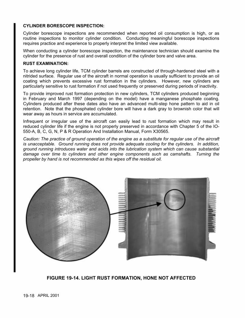
19-18
CYLINDER BORESCOPE INSPECTION:Cylinder borescope inspections are recommended when reported oil consumption is high, or asroutine inspections to monitor cylinder condition. Conducting meaningful borescope inspectionsrequires practice and experience to properly interpret the limited view available.When conducting a cylinder borescope inspection, the maintenance technician should examine thecylinder for the presence of rust and overall condition of the cylinder bore and valve area.
RUST EXAMINATION:To achieve long cylinder life, TCM cylinder barrels are constructed of through-hardened steel with anitrided surface. Regular use of the aircraft in normal operation is usually sufficient to provide an oilcoating which prevents excessive rust formation in the cylinders. However, new cylinders areparticularly sensitive to rust formation if not used frequently or preserved during periods of inactivity.To provide improved rust formation protection in new cylinders, TCM cylinders produced beginningin February and March 1997 (depending on the model) have a manganese phosphate coating.Cylinders produced after these dates also have an advanced multi-step hone pattern to aid in oilretention. Note that the phosphated cylinder bore will have a dark gray to brownish color that willwear away as hours in service are accumulated.Infrequent or irregular use of the aircraft can easily lead to rust formation which may result inreduced cylinder life if the engine is not properly preserved in accordance with Chapter 5 of the IO-550-A, B, C, G, N, P & R Operation And Installation Manual, Form X30565.Caution: The practice of ground operation of the engine as a substitute for regular use of the aircraftis unacceptable. Ground running does not provide adequate cooling for the cylinders. In addition,ground running introduces water and acids into the lubrication system which can cause substantialdamage over time to cylinders and other engine components such as camshafts. Turning thepropeller by hand is not recommended as this wipes off the residual oil.
FIGURE 19-14. LIGHT RUST FORMATION, HONE NOT AFFECTED
APRIL 2001

19-19
Light rust signatures which have not pitted the cylinder wall, or rust indications above the top ringtravel area, are not usually cause for concern. See Figure 19-14. Severe rust will pit the barrel walland can damage rings. See Figure 19-15. Such damage will usually be evident by low differentialcompression checks and high oil consumption. TCM'S WARRANTY DOES NOT COVER DAMAGEFROM RUST. Rust damage must be prevented by the operator and/or maintenance facility.
FIGURE 19-15. HEAVY RUST FORMATION, SURFACE PITTINGHAS ALTERED HONED PATTERN
CYLINDER WALL EXAMINATIONBorescope inspections of the cylinder wall are performed to assess the condition of the hone patternand identify abnormal wear patterns which can contribute to low differential compression readings orincreased oil consumption.The cylinder wall hone pattern consists of a carefully applied pattern of surface "scratches"introduced at the time of manufacture. These scratches aid in ring seating by allowing the ring andwall surface to wear into conformity to each other and provide a reservoir of oil for lubrication duringring travel. The cylinder walls and rings are designed to wear over the life of the engine, particularlyin the high pressure and temperature combustion area. The visible hone pattern in the upper portionof the bore may disappear during normal operation. SUCH NORMAL PATTERNS ARE NOTCAUSE FOR CYLINDER REMOVAL.The following figures show hone patterns in a new cylinder and at TBO for typical TCM cylinders.As can be seen from the photograph at TBO (Figure 19-17), cylinders which have a very light or nohone pattern in the upper portion of the bore can function normally, have normal oil consumptionand have acceptable differential compression checks. For this reason, the borescope inspectionshould be used in conjunction with differential compression checks and oil consumption trends toassess engine condition.
APRIL 2001
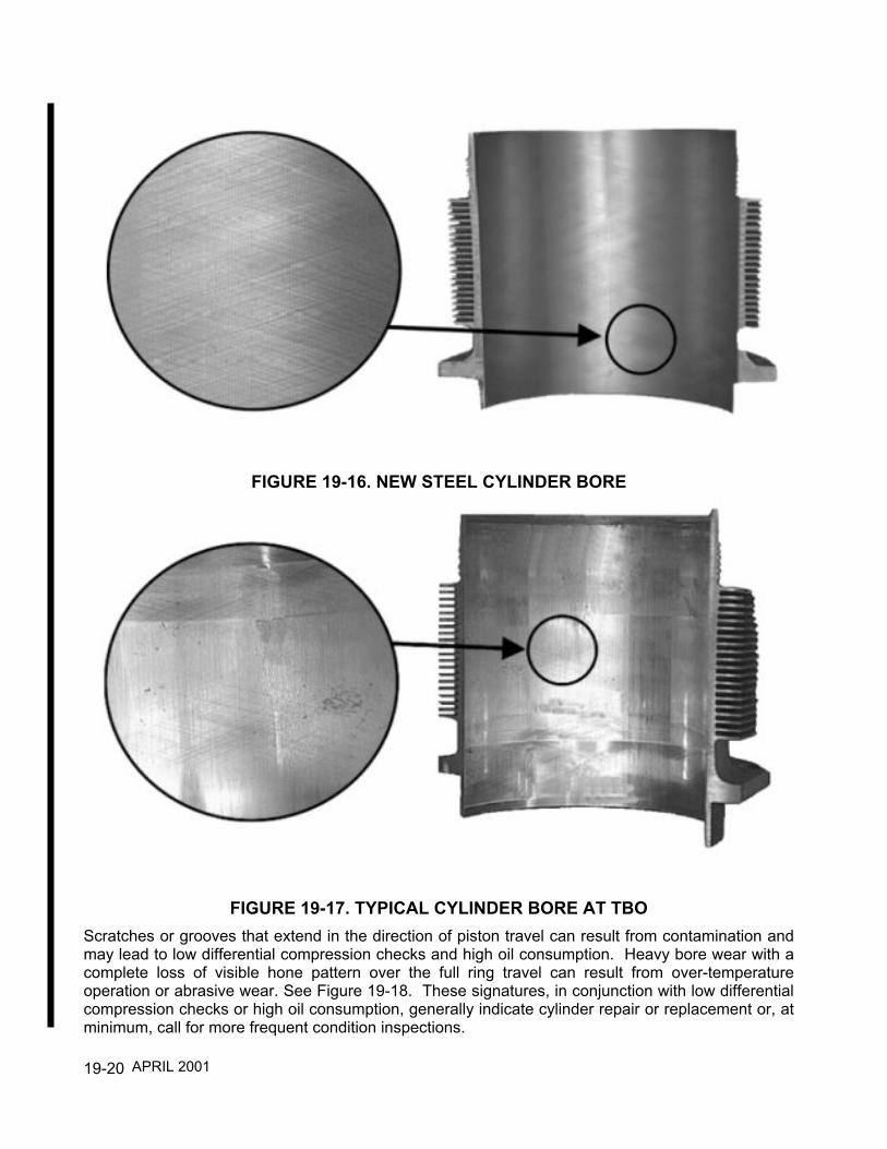
19-20
FIGURE 19-16. NEW STEEL CYLINDER BORE
FIGURE 19-17. TYPICAL CYLINDER BORE AT TBOScratches or grooves that extend in the direction of piston travel can result from contamination andmay lead to low differential compression checks and high oil consumption. Heavy bore wear with acomplete loss of visible hone pattern over the full ring travel can result from over-temperatureoperation or abrasive wear. See Figure 19-18. These signatures, in conjunction with low differentialcompression checks or high oil consumption, generally indicate cylinder repair or replacement or, atminimum, call for more frequent condition inspections.
APRIL 2001

19-21
FIGURE 19-18. HEAVILY WORN CYLINDER BOREOver time, the cylinder wall may develop a glazed coating which is generally beneficial to cylinderlife as a rust inhibitor. The glaze is a residue of hydrocarbon constituents and lead deposits whichserve as both a rust inhibitor and lubricant. Changes and variations in fuel constituents and types ofoil used in recent years may impact this beneficial coating. TCM's revised hone pattern, reduced oilcontrol ring tension and manganese phosphate coating are intended to offset this impact.
CYLINDER BORE INSPECTIONa. Inspect each cylinder for signatures of normal wear. See Figure 19-17. Cylinder walls which
appear to have minimum or no hone pattern are acceptable if the cylinder has acceptabledifferential compression readings and the engine has acceptable oil consumption.
b. Inspect each cylinder for signatures of light rust. See Figure 19-14. Light rust which has notresulted in pitting of the cylinder wall is acceptable. Several small, localized areas less than 1/16inch in diameter are acceptable as long as the total affected areas in any one cylinder does notexceed 1 inch in diameter. The affected areas must be separated by at least 1/2 inch. Rustabove the top ring travel is inconsequential and not cause for cylinder removal. Surfacediscoloration or staining is acceptable and will not result in any damage to the cylinder barrel or tothe piston rings.
c. Inspect each cylinder for signatures of heavy rust. See Figure 19-15. Cylinder walls which showheavy rust as characterized by pitting of the cylinder wall surface should be removed for repair orreplacement if the cylinder has low differential compression or the engine oil consumption is high.Areas of corrosion where the honed surfaces have been altered are of primary concern. Theseareas are normally very dark in contrast to the surrounding areas. Small localized areas less than1/2 inch in diameter are acceptable as long as there are no signatures of scoring or material pickup.
APRIL 2001

19-22
d. Inspect each cylinder for signatures of heavy wear. See Figure 19-18. Heavy bore wear isidentified as a complete loss of visible hone pattern over the full ring travel and will normally haveassociated low cylinder differential compression and/or high oil consumption. This generally willindicate a need for cylinder repair or replacement or, at minimum, call for more frequent conditioninspections.
e. Inspect each cylinder for signatures of scoring. A predominant amount of cylinder bore scratchesor grooves that extend in the direction of piston travel will normally lead to low differentialcompression checks and high oil consumption. This may also be identified by burnt or blisteredpaint on the exterior of the cylinder barrel. This will indicate a need for cylinder repair orreplacement.
OIL CONSUMPTION TREND MONITORINGAircraft piston engines continuously wear over their service life. One indication of the rate of wear,or indication of the need for inspection or service, is found in oil consumption trends. Everyowner/operator and maintenance facility should maintain formal records on oil consumption in theaircraft log book.Oil consumption can be expected to vary with each engine depending on the load, operatingtemperature, type of oil used and condition of the engine. A differential compression check andborescope inspection should be conducted if oil consumption exceeds one quart every three hoursor if any sudden change in oil consumption is experienced and appropriate action taken.It is important to note that the current technology of general aviation aircraft reciprocating enginesrequires a certain level of oil consumption to assure proper lubrication of the cylinder walls and rings.Aircraft engines operate under much greater loads and at higher temperatures than automotiveengines and require correspondingly greater oil use. In addition to lubrication, oil serves as acoolant and as a means to transport contaminants, wear particles, acids and moisture from theengine at oil changes. Frequent oil changes based on operating hours or calendar time are criticalto engine life. Approved oils are listed in Chapter 3.TCM 550 cylinder assemblies produced after February 1997 have revised oil ring tensions toproduce improved cylinder bore lubrication characteristics.The Cylinder Inspection Checklist Form on page 19-31 contains a means to record oil consumption.The Cylinder Inspection Checklist should be completed and maintained with the engine logbook. OILCONSUMPTION TRENDS ARE EXCELLENT INDICATORS OF CYLINDER BORE AND RINGCONDITION.
OIL CONSUMPTION TREND MONITORING PROCEDUREa. A formal oil consumption record should be generated for the engine installation. If oil
consumption is more than one quart every three hours of operation or if the oil consumption trendhas changed substantially, conduct the differential compression and borescope examinations inthis section. If the oil consumption trend is stable and the oil consumption is less than one quartevery three hours, continue with the inspection.
b. Record type of oil used.c. Record the number of quarts of oil added.d. Record oil change interval.
APRIL 2001
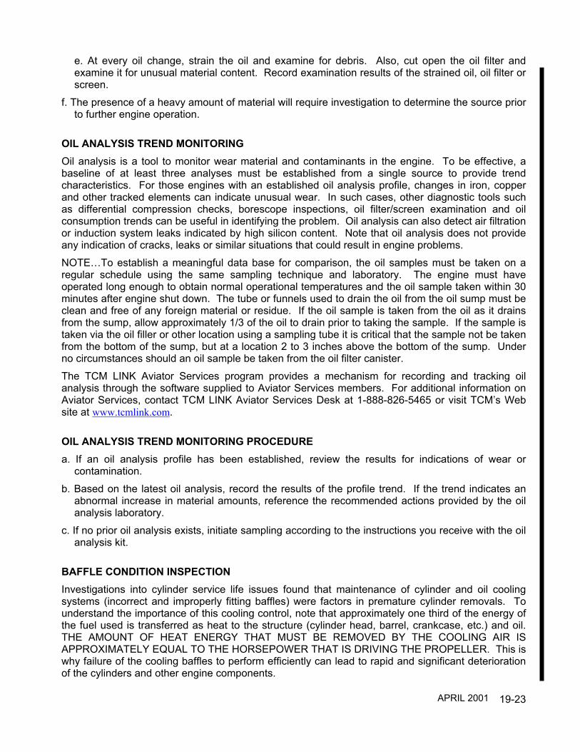
19-23
e. At every oil change, strain the oil and examine for debris. Also, cut open the oil filter andexamine it for unusual material content. Record examination results of the strained oil, oil filter orscreen.
f. The presence of a heavy amount of material will require investigation to determine the source priorto further engine operation.
OIL ANALYSIS TREND MONITORINGOil analysis is a tool to monitor wear material and contaminants in the engine. To be effective, abaseline of at least three analyses must be established from a single source to provide trendcharacteristics. For those engines with an established oil analysis profile, changes in iron, copperand other tracked elements can indicate unusual wear. In such cases, other diagnostic tools suchas differential compression checks, borescope inspections, oil filter/screen examination and oilconsumption trends can be useful in identifying the problem. Oil analysis can also detect air filtrationor induction system leaks indicated by high silicon content. Note that oil analysis does not provideany indication of cracks, leaks or similar situations that could result in engine problems.NOTE…To establish a meaningful data base for comparison, the oil samples must be taken on aregular schedule using the same sampling technique and laboratory. The engine must haveoperated long enough to obtain normal operational temperatures and the oil sample taken within 30minutes after engine shut down. The tube or funnels used to drain the oil from the oil sump must beclean and free of any foreign material or residue. If the oil sample is taken from the oil as it drainsfrom the sump, allow approximately 1/3 of the oil to drain prior to taking the sample. If the sample istaken via the oil filler or other location using a sampling tube it is critical that the sample not be takenfrom the bottom of the sump, but at a location 2 to 3 inches above the bottom of the sump. Underno circumstances should an oil sample be taken from the oil filter canister.The TCM LINK Aviator Services program provides a mechanism for recording and tracking oilanalysis through the software supplied to Aviator Services members. For additional information onAviator Services, contact TCM LINK Aviator Services Desk at 1-888-826-5465 or visit TCM’s Website at www.tcmlink.com.
OIL ANALYSIS TREND MONITORING PROCEDUREa. If an oil analysis profile has been established, review the results for indications of wear or
contamination.b. Based on the latest oil analysis, record the results of the profile trend. If the trend indicates an
abnormal increase in material amounts, reference the recommended actions provided by the oilanalysis laboratory.
c. If no prior oil analysis exists, initiate sampling according to the instructions you receive with the oilanalysis kit.
BAFFLE CONDITION INSPECTIONInvestigations into cylinder service life issues found that maintenance of cylinder and oil coolingsystems (incorrect and improperly fitting baffles) were factors in premature cylinder removals. Tounderstand the importance of this cooling control, note that approximately one third of the energy ofthe fuel used is transferred as heat to the structure (cylinder head, barrel, crankcase, etc.) and oil.THE AMOUNT OF HEAT ENERGY THAT MUST BE REMOVED BY THE COOLING AIR ISAPPROXIMATELY EQUAL TO THE HORSEPOWER THAT IS DRIVING THE PROPELLER. This iswhy failure of the cooling baffles to perform efficiently can lead to rapid and significant deteriorationof the cylinders and other engine components.
APRIL 2001
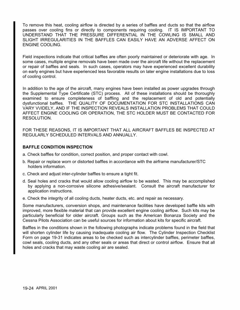
19-24
To remove this heat, cooling airflow is directed by a series of baffles and ducts so that the airflowpasses over cooling fins or directly to components requiring cooling. IT IS IMPORTANT TOUNDERSTAND THAT THE PRESSURE DIFFERENTIAL IN THE COWLING IS SMALL ANDSLIGHT IRREGULARITIES IN THE BAFFLES CAN EASILY HAVE AN ADVERSE AFFECT ONENGINE COOLING.
Field inspections indicate that critical baffles are often poorly maintained or deteriorate with age. Insome cases, multiple engine removals have been made over the aircraft life without the replacementor repair of baffles and seals. In such cases, operators may have experienced excellent durabilityon early engines but have experienced less favorable results on later engine installations due to lossof cooling control.
In addition to the age of the aircraft, many engines have been installed as power upgrades throughthe Supplemental Type Certificate (STC) process. All of these installations should be thoroughlyexamined to ensure completeness of baffling and the replacement of old and potentiallydysfunctional baffles. THE QUALITY OF DOCUMENTATION FOR STC INSTALLATIONS CANVARY V\/IDELY, AND IF THE INSPECTION REVEALS INSTALLATION PROBLEMS THAT COULDAFFECT ENGINE COOLING OR OPERATION, THE STC HOLDER MUST BE CONTACTED FORRESOLUTION.
FOR THESE REASONS, IT IS IMPORTANT THAT ALL AIRCRAFT BAFFLES BE INSPECTED ATREGULARLY SCHEDULED INTERVALS AND ANNUALLY.
BAFFLE CONDITION INSPECTIONa. Check baffles for condition, correct position, and proper contact with cowl.b. Repair or replace worn or distorted baffles in accordance with the airframe manufacturer/STC
holders information.c. Check and adjust inter-cylinder baffles to ensure a tight fit.d. Seal holes and cracks that would allow cooling airflow to be wasted. This may be accomplished
by applying a non-corrosive silicone adhesive/sealant. Consult the aircraft manufacturer forapplication instructions.
e. Check the integrity of all cooling ducts, heater ducts, etc. and repair as necessary.Some manufacturers, conversion shops, and maintenance facilities have developed baffle kits withimproved, more flexible material that can provide excellent engine cooling airflow. Such kits may beparticularly beneficial for older aircraft. Groups such as the American Bonanza Society and theCessna Pilots Association can be useful sources for information about kits for specific aircraft.Baffles in the conditions shown in the following photographs indicate problems found in the field thatwill shorten cylinder life by causing inadequate cooling air flow. The Cylinder Inspection ChecklistForm on page 19-31 indicates areas to be checked such as intercylinder baffles, perimeter baffles,cowl seals, cooling ducts, and any other seals or areas that direct or control airflow. Ensure that allholes and cracks that may waste cooling air are sealed.
APRIL 2001

19-25
Peripheral Baffle SealsImproperly Positioned
FIGURE 19-19. BAFFLE SEALS IMPROPERLY POSITIONED
APRIL 2001

19-26
Aft and Side Peripheral BaffleSeals Not Sealing Properly
FIGURE 19-20. BAFFLE SEALS NOT SEALING PROPERLY
APRIL 2001

19-27
FIGURE 19-21. BAFFLES WITH AIR GAPS
APRIL 2001

19-28
FIGURE 19-22. GAPS IN BAFFLE SEAL
APRIL 2001

19-29
INDUCTION SYSTEM EXAMINATIONImproper or inadequate maintenance of the air induction components of the aircraft engineinstallation can and often does result in the engine breathing unfiltered air. Unfiltered air containsparticulates which are abrasive to the engine, especially to the cylinder walls and ring faces.Induction system maintenance that emphasizes properly sealed filters, alternate air doors, and airducts can prevent much of that damage. Induction system deficiencies can often be detectedthrough oil analysis which identifies the contamination.In addition to the following see Chapter 14 of this manual and consult the aircraft maintenancemanual for information.a. Check the air filter for cleanliness, normal operation and the absence of gaps or leaks in the
filtering element. Check the air filter seal for potential bypass circuits from the filter. Correct orreplace as necessary in accordance with the airframe manufacturer/STC holders information.
b. Verify the integrity of the airbox by examining for alternate air circuits which can bypass thefiltering system. Any holes or bypass circuits found behind the filtering element should berepaired as required in accordance with the airframe manufacturer/STC holders information.
c. Verify the operation of the alternate air door and the integrity of the seal when in the closedposition. Verify the door operating mechanism for security when in the closed location. Replaceor repair as necessary in accordance with the airframe manufacturer/STC holders information.
d. If the operator conducts regular oil analyses, use the silicon content of the most recent analysisand the overall silicon trend to further assess the possibility of induction system leaks or pilotoperational issues such as extensive use of carburetor heat or alternate air during groundoperation.
e. Identify induction system inspection requirements for the specific aircraft in service and complywith all requirements for inspection and maintenance of the induction system.
COWLING INSPECTION AND COWL FLAP OPERATIONAL CHECKIn addition to baffle conditions, other components that affect airflow though the cowling must bereviewed. Supplemental equipment or modifications must not restrict cowl openings and exit areas.Abnormal temperatures can result from airflow blockage or restrictions which can lead to cylinderdamage. Cowl flap operation is also an integral part of engine cooling control.
a. Verify that equipment such as add-on accessories and their associated hardware does notrestrict cowl inlet, cowl outlet, and air flow through the cooling fins.
b. Verify cowl flap rigging and operation in accordance with the appropriate aircraft maintenancemanual as applicable.
IGNITION SYSTEM INSPECTIONAdvanced magneto to engine timing can cause elevated cylinder head temperatures. Maintain andadjust magnetos in accordance with the engine or magneto service instructions. Inspect themagneto harness and spark plugs and replace if needed.
a. Check magneto timing and adjust to specification. See Chapter 12 in regard to engine timing.b. Clean, gap and test spark plugs; replace as needed.c. Inspect ignition harness leads for damage; replace as needed.
APRIL 2001

19-30
FUEL SYSTEM SET-UPImproper maintenance and adjustment of the fuel system can be a significant factor in prematurecylinder removal. Engine operation and cooling are directly related to the correct set-up of the fuelsystem. In addition, improper fuel system settings can affect engine performance in terms of bothpower and response to throttle movement. For most installations, the available airflow is insufficientto cool the engine during high-power operation and additional fuel is required to providesupplemental cooling. Mixture control can also be used in cruise to maintain correct cylinder headtemperatures. Full rich fuel flows must be set properly in order to provide designed cooling margins.See Chapter 22 for fuel system adjustment procedures.To assist in this critical system adjustment, TCM has produced a video about the setup andmaintenance of TCM fuel injection systems as a supplement to existing information. The video (P/NX30650) may be ordered by contacting the TCM Customer Service Department.
AIRCRAFT ENGINE GAUGE VERIFICATIONTo ensure that the engine is operating within recommended limits for normal operation, the aircraftengine gauges must be verified for correct indications and any discrepancies rectified. Enginegauges include the tachometer, manifold pressure, fuel flow, oil pressure, oil temperature, cylinderhead temperature (CHT) and exhaust gas temperature (EGT).Caution…Inaccurate aircraft engine related gauges can cause operation outside of enginecertification and specification limits and can lead to decreased cylinder life. Aircraft gaugecalibration errors can be particularly harmful for high horsepower engines. Gauges must be re-marked for modified (STC) engines.
WARNINGSIGNIFICANT AIRCRAFT ENGINE GAUGE INACCURACIES CAN LEAD TO CYLINDERDETONATION WHICH CAN RESULT IN ENGINE STOPPAGE.
COMMENT ON ENGINE TOP OVERHAUL PROCEDURESIf the results of the cylinder inspection indicate that one or more cylinders should be removed fromthe engine, it is extremely important the cylinder removal, repair or replacement, and installation beconducted according to the following and instructions contained in the appropriate aircraftmanufacturer's instructions, TCM Overhaul Manual and other related TCM service documents forthe aircraft and engine under service.Evaluations of engine service issues and incidents in the field indicate that a number of engines thatexperience reduced service life can be attributed to improper field top overhaul procedures.Improper torque sequencing or procedures employed during reassembly can result in loss of enginecrankcase through-bolt torque.
WARNINGTHE USE OF IMPROPER PROCEDURES FOR CYLINDER REMOVAL AND REPLACEMENTCAN LEAD TO LOSS OF MAIN BEARING CRUSH AND ENGINE FAILURE.
To assist with the understanding of the proper procedures for engine top overhaul, TCM hasproduced a video that highlights the critical elements of a field top overhaul. The top overhaul video(P/N X30562) may be ordered by contacting the TCM Customer Service Department.
APRIL 2001

19-31
Cylinder Inspection Checklist FormInspecting Agency: ................................................ Date: Inspecting Mechanic:............................................. Aviator Services Member #: Aircraft Owner: ......................................................Aircraft Make/Model: ............................................. Aircraft Serial #: Aircraft Year: ......................................................... Registration #: Engine Model: ....................................................... Engine Serial #: Engine Hours: Time since major O/H ................... Time Since Top O/H:
1. Differential Compression Check Record Readings1a. Master Orifice Reading ............................................................................................................................. 1b. Record Differential Compression Values for Each Cylinder ..................................................................#1
#2 #3 #4 #5 #6
2. Cylinder Bore Inspection Check Inspection Results for Each Cylinder
2a - Normal Wear 2b - Light Rust 2C - Heavy Rust 2d - Heavy Wear 2e - Scoring��Cylinder #1.............................................. �Cylinder #2.............................................. �Cylinder #3.............................................. �Cylinder #4.............................................. �Cylinder #� ............................................... �Cylinder #6.............................................. ��
3. Oil Consumption Trend Monitoring Record Information3a. Record Oil Consumption - One (1) Quart Every ............................................................................................. Hours3b. Type of Oil Used .............................................................................................................................................. 3c. Record the Number of Quarts Added............................................................................................................... 3d. Record Oil Change Interval ............................................................................................................................. Hours�3e. Sump Oil Strained and Filter Contents Examined and Found to be: Clean
Light Material Heavy Material
4. Oil Analysis Trend Monitoring Check as Applicable4a. Oil Analysis Profile Established........................................................................................................................ Yes No4b. Latest Oil Analysis Indicates ........................................................................................................................... Normal Trend�
..................................................................................................................................................................... Abnormal Trend�4c. Oil Analysis Sampling Initiated ......................................................................................................................... Yes No
Oil Analysis Lab Used ......................................................................................................................................
(As Applicable)
APRIL 2001

19-32
5. Baffle Condition Inspection Check as Applicable5a. Baffles in Good Condition, Correct Position and Proper Contact ...............................................................................................5b. Replaced or Repaired Baffles .....................................................................................................................................................5c Inter-Cylinder Baffles Installed Properly ......................................................................................................................................5d. Holes and Cracks Sealed ...........................................................................................................................................................5e. Cooling / Heating Duct Condition Correct or Repaired ...............................................................................................................
6. Induction System Examination Check as Applicable6a. Air Filter Clean and Properly Installed.........................................................................................................................................6b. Air Box Inspected and Repaired as Required .............................................................................................................................6c. Alternate Air Door Sealing and Functioning Properly ..................................................................................................................
7. Cowling Inspection and Cowl Flap Operation Check as Applicable7a. No Restrictions in Cowling Inlet, Outlet or Cooling Fins..............................................................................................................7b. Proper Cowl Flap Rigging and Operation Verified ......................................................................................................................
8. Ignition System Inspection Check as Applicable8a. Magneto to Engine Timing Set at ..................................................... Left and Right Degrees BTDC8b. Spark Plugs Cleaned, Gapped, Tested and Replaced as Necessary.........................................................................................8c. Ignition Harness Inspected for Damage and Leads Replaced as Necessary .............................................................................
9. Fuel System Setup Check as Applicable9a. Idle Unmetered Fuel Pump Pressure Set at ............................................................................ PSI at RPM
Idle Fuel Mixture RPM Rise at Idle Cutoff = 25/50 RPM .............................................................................................................Full Throttle Metered Fuel Set at ....................................................................... GPH/LBS-HR at RPM
10. Aircraft Engine Gage Verification
10a. Verified accuracy of Tach, MP, Fuel Flow, CHT and EGT Gages ............................................................................................ 11. Flight Test
Flight Test Performed and All Parameters Within Specification
If Cylinder Repair or Replacement was Required Due to Results of the Preceding Inspections, Indicate Below.
Low Compression Rust Scored Oil Consumption OtherCylinder #1 ...............................................Cylinder #2 ...............................................Cylinder #3 ...............................................Cylinder #4 ...............................................Cylinder #5 ...............................................Cylinder #6 ...............................................
Comments: I hereby certify that I have performed the Cylinder Inpection and any of the items identified above that required repair, replacement orverification have been repaired, replaced or verified.
Mechanic's Signature: Date:
APRIL 2001

19-33
WARNINGFuel injection lines must not be bent or deformed. The fuel injection lines must besecurely clamped to the fuel line support brackets. Do not assemble in a bindingconfiguration.Single Cylinder RemovalDisconnect battery in accordance with the airframe manufacturer's instructions. Tag the propellerwith the warning "DO NOT TURN PROPELLER." Remove cowling and any airframe suppliedaccessories in accordance with the airframe manufacturer's instructions. Remove cylinder usingcylinder and piston removal instructions in the I0-550 Permold Series Overhaul Manual, FormX30568A.
NOTE...When the cylinder is removed with the spark plugs installed, inspection can beaccomplished by filling the inverted cylinder bore with nonflammable solvent and then inspected forleaks at the static seal areas.When cylinder is removed use the following information to clean pistons prior to dimensionalinspection.
PistonsDo not use wire brushes or scrapers of any kind. Soft or hard carbon deposits may yield to solventaction. If deposits remain, install tight fitting skirt protector dry blast the piston heads with soft grit orby the vapor grit method. Do not use sand shot, metal grit or glass beads. Ring grooves must becleaned by pulling lengths of binder twine or very narrow strips of crocus cloth through them. Do notuse automotive ring grooves scrapers, since the corner radii at the bottoms of the grooves and sideclearances must not be altered. Abrasive cloth must not be used on the piston skirts because thediameters and cam-ground contour must not be altered. Scored or burned pistons must bediscarded. After cleaning, thoroughly rinse pistons using a stoddard solvent to remove all debris.
RingsPiston rings must be replaced 100%.Before any repair procedures are performed after cleaning, the cylinder and it's related componentsmust be visually, fluorescent penetrant and magnetic particle Inspected as applicable in accordancewith the I0-550 Overhaul Manual, Form X30568A.
Single Cylinder ReassemblyAfter all cylinder components have been cleaned, inspected and repaired in accordance with TCMspecifications, reassemble cylinder in accordance with Cylinder and Piston Sub-Assembly of the I0-550 Permold Series Overhaul Manual, Form X30568A.
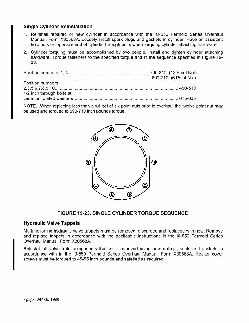
19-34
Single Cylinder Reinstallation1. Reinstall repaired or new cylinder in accordance with the IO-550 Permold Series Overhaul
Manual, Form X30568A. Loosely install spark plugs and gaskets in cylinder. Have an assistanthold nuts on opposite end of cylinder through bolts when torquing cylinder attaching hardware.
2. Cylinder torquing must be accomplished by two people, install and tighten cylinder attachinghardware. Torque fasteners to the specified torque and in the sequence specified in Figure 19-23.
Position numbers. 1, 4 ................................................................790-810 (12 Point Nut)................................................................. 690-710 (6 Point Nut)
Position numbers2,3,5,6,7,8,9,10................................................................................................... 490-5101/2 inch through bolts atcadmium plated washers .................................................................................... 615-635NOTE…When replacing less than a full set of six point nuts prior to overhaul the twelve point nut maybe used and torqued to 690-710 inch pounds torque.
Hydraulic Valve TappetsMalfunctioning hydraulic valve tappets must be removed, discarded and replaced with new. Removeand replace tappets in accordance with the applicable instructions in the I0-550 Permold SeriesOverhaul Manual, Form X30568A.Reinstall all valve train components that were removed using new o-rings, seals and gaskets inaccordance with in the I0-550 Permold Series Overhaul Manual, Form X30568A. Rocker coverscrews must be torqued to 45-55 inch pounds and safetied as required.
FIGURE 19-23. SINGLE CYLINDER TORQUE SEQUENCE
APRIL 1998

19-35
CAUTION...When performing dimensional inspection the following "Service Limits" may be used.However, they are only intended as a guide for re-use when performing maintenance of the engineprior to major overhaul. Parts with dimensions or fits that exceed service limits must not be re-used.Parts with values up to and including service limits may be re-used, however, judgment should beexercised considering the PROXIMITY of the engine to its recommended overhaul time.
When performing cylinder assembly repairs prior to engine TBO the following dimensional limits maybe used.
CYLINDER ASSEMBLY SERVICE LIMITS IO-550-A, B & C
REF. DESCRIPTION SERVICELIMIT
CYLINDER ASSEMBLY1. Cylinder bore (lower 4-1/4" of barrel) ............................................. Diameter: See Figure
19-252. Cylinder bore choke (at 5.75" from open end of barrel) ......................Taper: See Figure
19-253. Cylinder bore out-of-round............................................................................ : 0.00204. Cylinder bore.............................................................. Allowable Oversize: See Figure
19-255. Cylinder bore surface roughness (Nitride Barrels)
using 180 grit stone, cross hatch.......................................................... Angle:Finish (in micro inches)......................................................................... Ra:
22° - 32°30-50
6. Cylinder barrel in crankcase........................................................... Diameter: 0.0100L7. Intake valve seat insert in cylinder head ........................................ Diameter: 0.012T8. Intake valve guide in cylinder head ................................................ Diameter: 0.0025T9. Exhaust valve guide in cylinder head............................................. Diameter: 0.0030T10. Exhaust valve seat insert in cylinder head ..................................... Diameter: 0.0100T11. Intake valve seat..................................................................................Width: See Figure
19-2512. Exhaust valve seat...............................................................................Width: See Figure
19-25Exhaust valve seat-to-valve guide axis ................................................ Angle: 45°-00'Intake valve seat-to-valve guide axis ................................................... Angle: 60°-15'
ROCKER ARMS AND SHAFTS13. Rocker shaft in cylinder head bosses ............................................ Diameter: 0.003L
Rocker shaft in rocker arm bearing ................................................ Diameter: 0.0040L14. Rocker arm bushing bore ........................................... Finish Bore Diameter: 0.8755
Rocker arm bushing (inside)....................................... Finish Bore Diameter: 0.751515. Rocker Arm.......................................................................... Side Clearance: 0.0350L16. Intake valve in guide....................................................................... Diameter: 0.0050L17. Exhaust valve in guide ................................................................... Diameter: 0.0062L18. Intake valve face (to stem axis) ............................................................ Angle: 60°-15'19. Exhaust valve face (to stem axis)......................................................... Angle: 45°-30'20. Intake valve face (gauge line) to stem............................................... Length: 4.71421. Exhaust valve .................................................................................... Length: Replace 100%
APRIL 2001

19-36
REF. DESCRIPTION SERVICELIMIT
22. Intake and exhaust valve seat-to-stem (full indicator reading).........Run-out: 0.004023. Rocker arm foot-to-valve stem (dry valve gear lash).................................... : 0.2000
PISTONS, RINGS AND PINS24. Piston (bottom of skirt) in cylinder Diameter: 0.0110L25. Top piston ring in groove Side Clearance: 0.006L26. Second piston ring in groove Side Clearance; 0.006L27. Third piston ring in groove .....................................................Side Clearance: 0.0075L28. Fourth piston ring in groove ...................................................Side Clearance: 0.0100L29. Top ring gap at 1.00 ± .50 depth (in cylinder barrel)................................ Gap: 0.04430. Second ring gap at 1.00 ± .50 depth (in cylinder barrel)...................... Gap: 0.05031. Third ring gap at 1.00 ± .50 depth (in cylinder barrel).............................. Gap: 0.03632. Fourth ring gap at 1.00 ± .50 depth (in cylinder barrel) ........................... Gap: 0.03133. Piston pin in piston (standard or 0.005' oversize).............................Diameter: 0.0015L34. Piston pin...........................................................................................Diameter: 1.1245
Piston pin (0.005 oversize) ...............................................................Diameter: 1.129535. Piston pin in cylinder ................................................................End Clearance: 0.090L36. Piston pin in connecting rod bushing................................................Diameter: 0.0040L37. Bushing in connecting rod.................................................................Diameter: 0.0050T38. Bolt in connecting rod........................................................................Diameter: 0.0018L39. Connecting rod bearing on crankpin.................................................Diameter: 0.0060L40. Connecting rod on crankpin.....................................................End Clearance: 0.016041. Connecting bearing and bushing twist or convergence per inch of length : 0.001042. Hydraulic tappet in crankcase...........................................................Diameter: 0.0035L
SPRING TEST DATA43. Inner valve spring 631521 compressed to 1.230 in. length....................Load: 82 Lbs
Inner valve spring 631521 compressed to 1.746 in. length....................Load: 29 Lbs.44. Outer valve spring 637837 compressed to 1.275 in. length...................Load: 118 Lbs.
Outer valve spring 637837 compressed to 1.791 in. length...................Load: 46 Lbs.45. Installed outer valve spring ................................................................... Height: 1.791
NOTES: T=Tight L=LooseUse .005" oversize rings.Gap for second ring must be at least .006 larger than gap for top ring.
APRIL 2001
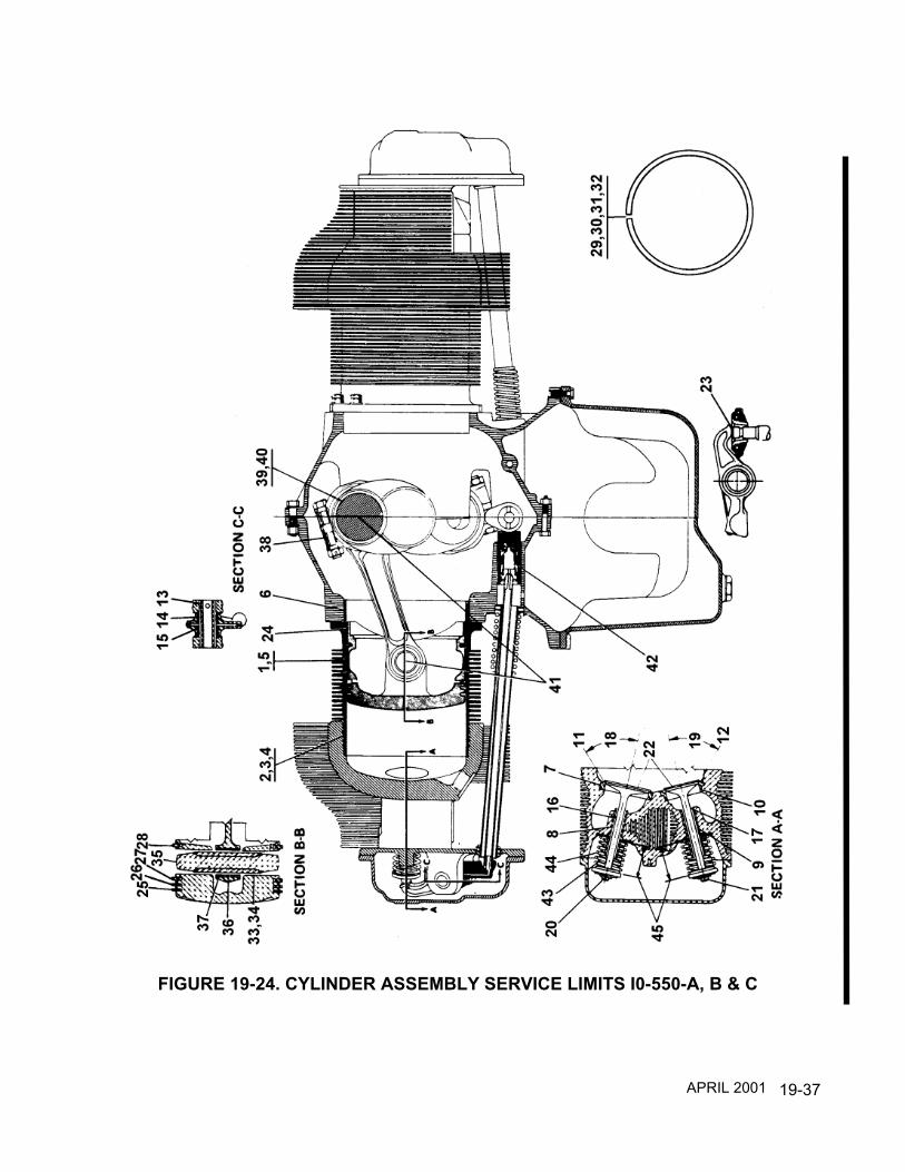
19-37
FIGURE 19-24. CYLINDER ASSEMBLY SERVICE LIMITS I0-550-A, B & C
APRIL 2001
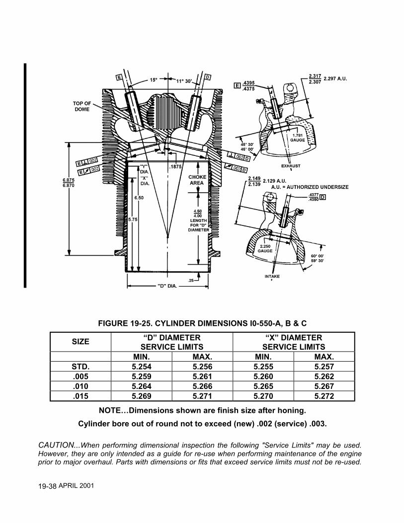
19-38
CAUTION...When performing dimensional inspection the following "Service Limits" may be used.However, they are only intended as a guide for re-use when performing maintenance of the engineprior to major overhaul. Parts with dimensions or fits that exceed service limits must not be re-used.
FIGURE 19-25. CYLINDER DIMENSIONS I0-550-A, B & C
SIZE “D” DIAMETERSERVICE LIMITS
“X” DIAMETERSERVICE LIMITS
MIN. MAX. MIN. MAX.STD. 5.254 5.256 5.255 5.257.005 5.259 5.261 5.260 5.262.010 5.264 5.266 5.265 5.267.015 5.269 5.271 5.270 5.272
NOTE…Dimensions shown are finish size after honing.Cylinder bore out of round not to exceed (new) .002 (service) .003.
APRIL 2001

19-39
Parts with values up to and including service limits may be re-used, however, judgment should beexercised considering the PROXIMITY of the engine to its recommended overhaul time.
When performing cylinder assembly repairs prior to engine TBO the following dimensional limits maybe used.
CYLINDER ASSEMBLY SERVICE LIMITS IO-550-G, N, P & RREF. DESCRIPTION SERVICE
LIMITCYLINDERS
1. Cylinder bore (lower 4-1/4" of barrel)...............................Diameter: See Figure19-27
2. Cylinder bore choke (at 5.75" from open end of barrel) ........Taper: See Figure19-27
3. Cylinder bore out-of-round.............................................................. : 0.00204. Cylinder bore................................................ Allowable Oversize: See Figure
19-275. Cylinder bore surface roughness (Nitrided Barrels)
using 180 grit stone,, cross hatch..........................................Angle:Finish (in micro inches).............................................................. Ra:
22° - 32°30-50
6. Cylinder barrel in crankcase ............................................Diameter: 0.0100L7. Intake valve seat insert in cylinder head..........................Diameter: 0.012T8. Intake valve guide in cylinder head .................................Diameter: 0.0025T9. Exhaust valve guide in cylinder head ..............................Diameter: 0.0030T10. Exhaust valve seat insert in cylinder head ......................Diameter: 0.0100T11. Intake valve seat .................................................................. Width: See Figure
19-2712. Exhaust valve seat............................................................... Width: See Figure
19-27Exhaust valve seat-to-valve axis ......................................... Angle: 45° - 00'Intake valve seat-to-valve guide axis................................... Angle: 60° - 15'
ROCKER ARMS AND SHAFTS13. Rocker Shaft in rocker arm bearing.................................Diameter: 0.0040L14. Rocker arm bushing bore ................................................Diameter: 0.8755
Rocker arm bushing (inside)........................Finish Bore Diameter: 0.751515. Rocker arm............................................................Side Clearance: 0. 0150L16. Intake valve in guide .......................................................Diameter: 0.0050L17. Exhaust valve in guide ....................................................Diameter: 0.0062L18. Intake valve face (to stem axis) .............................................Angle: 60° - 15'19. Exhaust valve face (to stem axis)..........................................Angle: 45° - 30'20. Intake valve face (gauge line) to stem................................Length: 4.71421. Exhaust Valve ....................................................................Length: Replace 100%
APRIL 2001
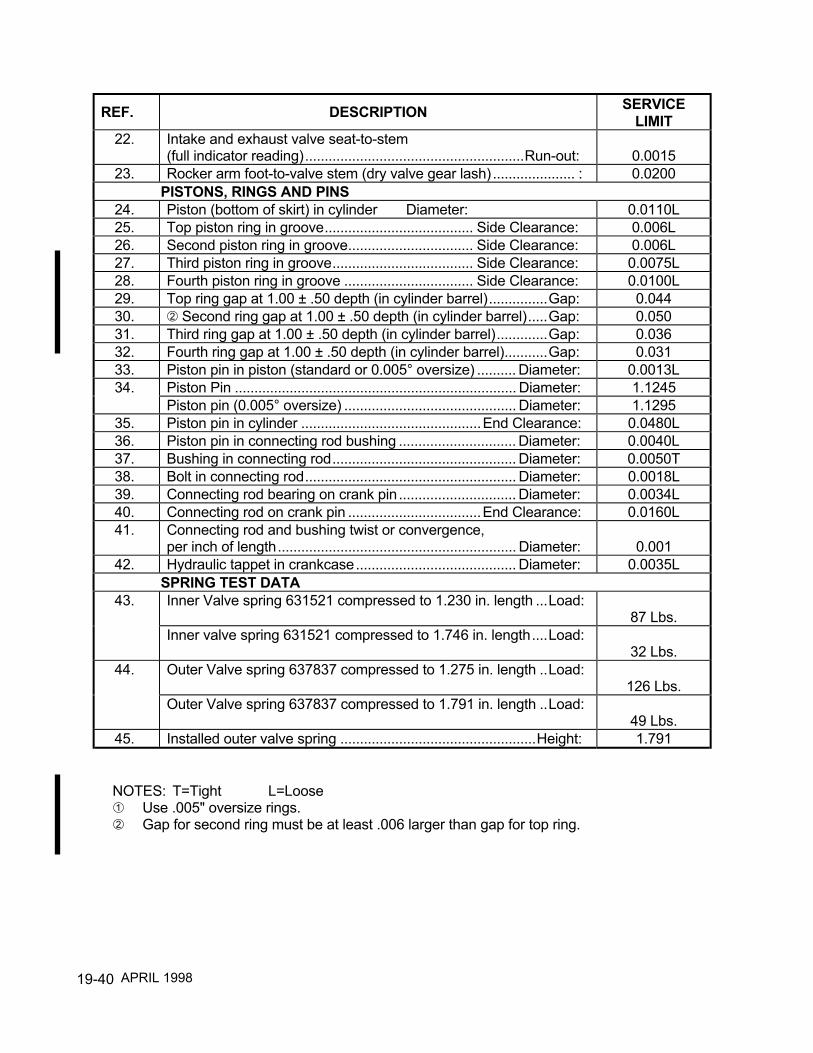
19-40
REF. DESCRIPTION SERVICELIMIT
22. Intake and exhaust valve seat-to-stem(full indicator reading)........................................................Run-out: 0.0015
23. Rocker arm foot-to-valve stem (dry valve gear lash) ..................... : 0.0200PISTONS, RINGS AND PINS
24. Piston (bottom of skirt) in cylinder Diameter: 0.0110L25. Top piston ring in groove...................................... Side Clearance: 0.006L26. Second piston ring in groove................................ Side Clearance: 0.006L27. Third piston ring in groove.................................... Side Clearance: 0.0075L28. Fourth piston ring in groove ................................. Side Clearance: 0.0100L29. Top ring gap at 1.00 ± .50 depth (in cylinder barrel)...............Gap: 0.04430. Second ring gap at 1.00 ± .50 depth (in cylinder barrel).....Gap: 0.05031. Third ring gap at 1.00 ± .50 depth (in cylinder barrel).............Gap: 0.03632. Fourth ring gap at 1.00 ± .50 depth (in cylinder barrel)...........Gap: 0.03133. Piston pin in piston (standard or 0.005° oversize) .......... Diameter: 0.0013L34. Piston Pin ........................................................................ Diameter: 1.1245
Piston pin (0.005° oversize) ............................................ Diameter: 1.129535. Piston pin in cylinder ..............................................End Clearance: 0.0480L36. Piston pin in connecting rod bushing .............................. Diameter: 0.0040L37. Bushing in connecting rod............................................... Diameter: 0.0050T38. Bolt in connecting rod...................................................... Diameter: 0.0018L39. Connecting rod bearing on crank pin.............................. Diameter: 0.0034L40. Connecting rod on crank pin ..................................End Clearance: 0.0160L41. Connecting rod and bushing twist or convergence,
per inch of length............................................................. Diameter: 0.00142. Hydraulic tappet in crankcase......................................... Diameter: 0.0035L
SPRING TEST DATA43. Inner Valve spring 631521 compressed to 1.230 in. length ...Load:
87 Lbs.Inner valve spring 631521 compressed to 1.746 in. length....Load:
32 Lbs.44. Outer Valve spring 637837 compressed to 1.275 in. length ..Load:
126 Lbs.Outer Valve spring 637837 compressed to 1.791 in. length ..Load:
49 Lbs.45. Installed outer valve spring ..................................................Height: 1.791
NOTES: T=Tight L=LooseUse .005" oversize rings.Gap for second ring must be at least .006 larger than gap for top ring.
APRIL 1998

19-41
FIGURE 19-26. CYLINDER ASSEMBLY SERVICE LIMITS I0-550-G, N, P & R
APRIL 2001

19-42
FIGURE 19-27. CYLINDER DIMENSIONS I0-550-G, N, P & R
SIZE “D” DIAMETERSERVICE LIMITS
“X” DIAMETERSERVICE LIMITS
MIN. MAX. MIN. MAX.STD. 5.254 5.256 5.255 5.257.005 5.259 5.261 5.260 5.262 .010 5.264 5.266 5.265 5.267
NOTE…Dimensions shown are finish size after honing.Cylinder bore out of round not to exceed (new) .002 (service) .003.
Applies to cylinder part numbers 653452, 653454 or later revisions only.
APRIL 2001

20-1
CHAPTER 20
CRANKCASE
SECTION PAGE20-1 Crankcase Description ........................................... 20-220-2 Crankcase Maintenance......................................... 20-3
Crankcase Cracks .................................................. 20-3Crankcase .............................................................. 20-4Studs ...................................................................... 20-4Engine Mounts........................................................ 20-5Crankcase Separation ............................................ 20-5Crankcase/Starter Needle Bearing Installation....... 20-5
FIGURE PAGE20-1 Crankcase Description ........................................... 20-220-2 Inspection of Crankcase Non Critical Area............. 20-320-3 Inspection of Crankcase Critical (White) and
Non Critical (Shaded) Areas................................... 20-420-4 Crankcase Needle Bearing Installer ....................... 20-620-5 Modified Crankcase Needle Bearing Tool .............. 20-6
APRIL 1998

20-2
20-1 CRANKCASE DESCRIPTIONThe crankcase is the foundation of the engine. It supports the crankshaft, camshaft, variousgears accessories, cylinders and various brackets. The crankcase provides a tight enclosureand oil galleries for lubrication. The crankcase is sufficiently rigid and strong to preventmisalignment of the crankshaft, camshaft and bearings. The crankcase is made of aluminumalloy.Two aluminum alloy castings are joined along the vertical center plane to form the completecrankcase. The individual castings (with studs and inserts) will be referred to as the "leftcrankcase" and "right crankcase" throughout this chapter.Bosses molded in the crankcase castings are line bored in the assembled castings to formbearings for the camshaft and saddles for precision crankshaft main bearing inserts. Guidesare bored through lateral bosses for hydraulic tappets and on the left crankcase half for thegovernor drive gear shaft. A needle bearing bore is located on the right crankcase half at therear main bearing saddle for the starter adapter needle bearing.Cylinder mounting pads on the left crankcase are farther forward than the correspondingpads on the right crankcase to permit each connecting rod to work on a separate crankpin.There are seven studs and two through bolts for attaching cylinder base flanges. Thepropeller governor mount pad is located on the left hand lower front corner of the left casehalf. On the right permold crankcase an alternator pad is located at the front ahead of the #5cylinder mount pad.The crankcase interior is ventilated by a breather that is part of the oil filler neck inserted intothe left crankcase half in a machined hole between the #2 and #4 cylinders .
FIGURE 20-1. CRANKCASE DESCRIPTION
APRIL 1998

20-3
20-2 CRANKCASE MAINTENANCECAUTION...Repair of the crankcase must be performed by repair facilities certified to performspecialized crankcase repairs.
WARNINGWeld repairs must not be performed in the critical (white) areas of thecrankcase as shown in Figure 20-3.TCM has established that welding of the crankcase is an acceptable repair process. Theweld procedure must conform with approved TCM repair standards and the dimensionalintegrity of the crankcase must be maintained.
Crankcase CracksCritical (white) and non-critical (shaded) areas are illustrated in Figure 20-3. If a crack isobserved in any of the non-critical (shaded) areas that is less than two (2) inches in length,the crack should be scribe marked at its extremities and re-inspected for crack progression atthe next 50 hours of operation. If no progression is observed and no additional cracks arefound, continue to inspect at regular intervals not to exceed 100 hours duration.If a crack is observed in any non-critical (shaded) area that is more than two (2) inches inlength, or if a previously observed crack has progressed to two (2) or more inches in length,repair or replace the crankcase prior to further flight. If any crack is observed in a critical(white) area, repair or replace the crankcase or engine prior to further flight.
Reasons for crankcase replacement:1. Any crack in the critical (white) areas.2. Any crack two (2) inches or more in length in the non-critical (shaded) area.3. Any crack that is leaking oil (not seeping) .
FIGURE 20-2. INSPECTION OF CRANKCASE NON CRITICAL AREA
APRIL 2001

20-4
CrankcaseLeaking gaskets must be replaced. Remove component, replace gasket and re-installcomponent in accordance with applicable system or component section in the I0-550Permold Series Overhaul Manual, Form X30568A. Exercise judgment as to the extent ofdisassembly required. During reassembly, insure that all reinstalled components are properlytorqued and safetied.
StudsThe replacement of crankcase studs or helical coils will require component removal andreplacement in accordance with the applicable component system section in the I0-550Permold Series Overhaul Manual, Form X30568A. During reassembly, insure that allreinstalled components are properly torqued and safetied .
FIGURE 20-3. INSPECTION OF CRANKCASE CRITICAL (WHITE) ANDNON CRITICAL (SHADED) AREAS
APRIL 1998

20-5
Engine MountsReplace engine shock mounts in accordance with the airframe manufacturer's instructions.Replace any cracked or broken engine mounts in accordance with in the I0-550 PermoldSeries Overhaul Manual, Form X30568A.
CAUTION...When relieving engine weight from the airframe, the engine hoist must beattached to the engine lifting eyes only.
NOTE...Place a support at the load bearing area of aircraft tail to prevent damage to theairframe.
Crankcase SeparationIf the crankcase halves must be separated, remove the engine from airframe in accordancewith the I0-550 Permold Series Overhaul Manual, Form X30568A and the airframemanufacturer's instructions.. Engine disassembly, cleaning, inspection, repair, replacementand assembly must be accomplished in accordance with the I0-550 Permold Series OverhaulManual, Form X30568A.
NOTE...Exercise judgment in determining how far systems and components should bedisassembled.
Any maintenance of engine systems and components removed from engine must beperformed in accordance with that particular system or component chapter of this manual.
CAUTION...Dimensional inspection of the crankcase and crankcase internal componentsmust be performed in accordance with the I0-550 Permold Series Overhaul Manual, FormX30568A. Prior to dimensional inspection, insure that the part conforms with all visual,fluorescent penetrant, magnetic particle or ultrasonic inspection requirements.
All crankcase repairs must be performed in accordance with the I0-550 Permold SeriesOverhaul Manual, Form X30568A. Any non TCM supplied accessory that was disassembledfor maintenance must be re-assembled in accordance with the applicable accessorymanufacturer's instructions. Any maintenance involving crankcase separation will require anacceptance test, oil consumption determination, reinstallation in airframe and test flight inaccordance with the I0-550 Permold Series Overhaul Manual, Form X30568A.
Crankcase/Starter Needle Bearing InstallationIf a new crankcase needle bearing has to be installed in the engine prior to overhaul, use amodified needle bearing tool and fixture shown in Figures 20-4 and 20-5 on the followingpage. Replace the needle bearing in accordance with the I0-550 Permold Series OverhaulManual, Form X30568A .
APRIL 1998

20-6
FIGURE 20-4. CRANKCASE NEEDLE BEARING INSTALLER
FIGURE 20-5. MODIFIED CRANKCASE NEEDLE BEARING TOOL
APRIL 1998

21-1
CHAPTER 21
ENGINE DRIVE TRAIN
SECTION PAGE21-1 Engine Drive Train Description ...................................... 21-2
Crankshaft Description .............................................. 21-4Connecting Rod Description ...................................... 21-5Camshaft Description ................................................ 21-6Idler Gear Description................................................ 21-6
21-2 Engine Drive Train Maintenance.................................... 21-7Crankshaft Nose Oil Seal .......................................... 21-7Engine Drive Train Component Removal .................. 21-9
FIGURE PAGE21-1 Engine Drive Train Description ...................................... 21-321-2 Crankshaft Description................................................... 21-421-3 Connecting Rod Description .......................................... 21-521-4 Camshaft Description..................................................... 21-621-5 Idler Gear Description .................................................... 21-621-6 Helix Pattern Application ................................................ 21-721-7 Crankshaft Oil Seal ........................................................ 21-8
APRIL 1998

21-2
21-1 Engine Drive Train DescriptionWhen starting engine, torque is transmitted from the starter (13) through starter adaptercomponents (14 through 19) to crankshaft gear (1). As worm-wheel (17) is turned, the springmounted on its hub, is tightened to grip the shaftgear (18) drum. After engine is started thespring returns to its normal position releasing the shaftgear and disengaging the starter.Torque is transmitted to the alternator by a face gear (21) mounted on the crankshaft.Torque from the crankshaft (2) is transmitted by the crankshaft gear (1) directly to the idlergear (10) and the camshaft gear (3).The idler gear, rotating in a counterclockwise direction, drives the magneto drive gears (11,12 ). Optional accessories mounted on the crankcase upper rear are driven by internalsplines of magneto drive gears.The fuel pump coupling is driven directly from the crankshaft gear (1). The splined end of theoil pump drive gear (8) mates with the internal splines of the camshaft gear and transmitstorque to the oil pump driven gear (9). The governor drive bevel gear (6) is keyed to thecamshaft (4) and meshes with and drives the governor drive bevel gear (7).Shown below are the accessory gear to crankshaft gear drive ratios. The item numberscorrespond with those shown in Figure 21-1, "Engine Drive Train Description. "
ITEM DESCRIPTION GEAR RATIO1. Crankshafts Gears ................................................ 1:12. Crankshaft............................................................. 13. Camshaft Gear...................................................... 1:0.54. Camshaft............................................................... 1:0.55. Hydraulic Tappet ................................................... —6. Governor Drive Bevel Gear................................... 1:0.57. Governor Driven Bevel Gear................................. 1:18. Oil Pump Drive Shaftgear ..................................... 1:0.59. Oil Pump Driven Gear ........................................... 1:0.510. Idler Gear Assembly.............................................. 1:0.65211. Right Magneto Drive Gear .................................... 1:1.512. Left Magneto Drive Gear....................................... 1:1.513. Starter ................................................................... 48:114. Starter Coupling .................................................... —15. Worm Drive Shaft.................................................. 48:116. Starter Worm Gear................................................ 48:117. Starter Worm Wheel.............................................. 3:118. Starter Shaftgear................................................... 3:119. Alternator............................................................... 3:120. Alternator Driven Gear .......................................... 3:121. Alternator Drive Gear ............................................ 1:1
APRIL 1998

21-3
FIGURE 21-1. ENGINE DRIVE TRAIN DESCRIPTION

21-4
Crankshaft DescriptionThe crankshaft is made of aircraft quality steel. The crankshaft has five, machined, mainjournals which rotate on the bearings in the crankcase. Six, machined, rod journals providefor attachment of the connecting rod assemblies.The following shows the method of numbering the crankshaft main journals, connecting rodjournals and crankshaft cheeks which are identified by letters and location numbers.The method of numbering the crankshaft journals and cheeks is illustrated in Figure 21-2.Main journals, rod journals, and crankshaft cheeks are identified by letters and locationnumbers.
(a) Main Journal - M.J.(b) Rod Journal - R.J.(c) Crankshaft Cheek - C.C.
Counterweights are supplied in matched pairs with the bushings installed. This is necessaryto insure that their weight difference does not exceed 2 grams.The counterweight order number designates the vibration order the counterweight isabsorbing. If a vibration occurs six times per revolution, the counterweight which has beentuned to counteract this frequency of vibration is a 6th order counterweight. Similarly, if avibration occurs five times per revolution, the counteracting counterweight is a 5th ordercounterweight.Two sixth order counterweights are installed on the #2 cheek hangers. The #5 cheekhangers support one fifth and one fourth order counterweight. It does not matter on whichside of a cheek a particular counterweight is installed.The crankshaft gear is heated prior to installation to obtain a shrink fit. The gear is positionedon the crankshaft by a dowel pin The crankshaft gear incorporates a square drive hole thataccepts the square drive fuel pump coupling providing a direct drive for the fuel pump. Thegear also has a timing mark to provide a means of insuring correct crankshaft to camshafttiming.The alternator drive gear, is attached to the flange just behind the #5 main journal location atthe front of the crankshaft and is secured by four bolts and lockplates.
FIGURE 21-2. CRANKSHAFT DESCRIPTION
APRIL 1998

21-5
A neoprene oil seal, which is stretched over the crankshaft flange, and a split retainer ringare seated between the crankcase castings in the front shaft exit area and is sealed to thecrankshaft by a helical spring inside the seal's cavity.
Connecting Rod DescriptionThe connecting rods are made of aircraft quality steel. The plain type connecting rod largediameter end, which attaches to the crankshaft crankpin or rod journal, is fitted with a capand two (2)- piece bearing. The bearing cap is held to the main rod by special bolts and nuts.The portion of the rod between the crankpin and piston pin ends is called the "I" beam. A splitsteel backed bronze bushing is pressed into the piston pin end and machined for a precisionpin to bushing fit. Weight variation of connecting rods between opposing bays, Example: #5and #6 connecting rods, is limited to 1/2 ounce or 14.175 grams.
FIGURE 21-3. CONNECTING ROD DESCRIPTION

21-6
Camshaft DescriptionThe camshaft is made of aircraft quality steel. The forging is machined on four (4) mainjournals, nine cam lobes and the gear mount flange at the rear of the camshaft. The mainjournals ride within the crankcase camshaft bores. The hydraulic tappet movement inwardand outward in their bores is caused by the eccentric shape of the cam lobes. The lobes andjournals are ground and hardened. Movement of the tappets open and close the intake andexhaust valves within the cylinder head by mechanical linkage of the pushrods and rockerarms. The valves opening and closing is synchronized with piston position due to timing ofthe camshaft and crankshaft gears. Four unequally spaced bolts retaining the gear to thecamshaft insure proper positioning, locating the gear’s timing mark in relation to the camlobes. The camshaft gear incorporates a splined drive for driving the engine oil pump. A frontmounted bevel gear drives the prop governor bevel gear.
Idler Gear DescriptionThe idler gear support pin supports the idler gear. The bushing in the crankcase supports theforward part of the idler gear support pin shaft. The idler gear is driven directly by thecrankshaft. The idler gear drives the left and right magneto accessory drive gears.
FIGURE 21-4. CAMSHAFT DESCRIPTION
FIGURE 21-5. IDLER GEAR DESCRIPTION
APRIL 1998

21-7
21-2 Engine Drive Train MaintenanceCrankshaft Nose Oil SealThe crankshaft nose oil seal may be replaced according to the following instructions:
WARNINGTo prevent starting of engine before moving the crankshaft accomplish thefollowing:
a. Disconnect all spark plug leads.b. Verify magneto switches are connected to magnetos, that they are in the
"OFF" Position and "P" leads are grounded.c. Throttle position "CLOSED."d. Mixture control "IDLE-CUT-OFF."e. Set brakes and block aircraft wheels.f. Insure that aircraft tie-downs are installed and verify that the cabin door
latch is open.g. Do not stand within the arc of the propeller blades while turning the
propeller.Preparation1. Remove oil seal.2. Clean surfaces thoroughly making certain that no debris remains on the shaft or in the
seal counterbore. Wash seal area with solvent.3. Remove any plating in the one inch area shown in Figure 21-6, "Helix Pattern
Application." Remove plating by working a piece of very fine emery cloth back and fortharound the shaft. This should blend the finish uniformly without leaving any lines(scratches).-
1. See Figure 21-6, "Helix Pattern Application." Apply helix using a strip of 180 grit emerycloth approximately one half inch wide. Do approximately one quarter of the surfaceindicated at a time, stroking the cloth outward toward the propeller flange in the directionof rotation (CCW) towards you using maximum hand pressure. Reverse direction for lefthand rotating engines. This should result in a 30° pattern similar to that illustrated inFigure 21-6, "Helix Pattern Application." After doing the first portion rotate crankshaft byhand to make next portion available. Apply the same pattern again and continuecompletely around the crankshaft in this manner.
2. Repeat cleaning operation.
FIGURE 21-6. HELIX PATTERN APPLICATION
APRIL 2001
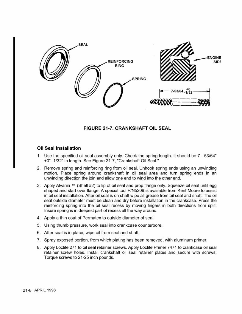
21-8
Oil Seal Installation1. Use the specified oil seal assembly only. Check the spring length. It should be 7 - 53/64"
+0” -1/32" in length. See Figure 21-7, "Crankshaft Oil Seal."2. Remove spring and reinforcing ring from oil seal. Unhook spring ends using an unwinding
motion. Place spring around crankshaft in oil seal area and turn spring ends in anunwinding direction the join and allow one end to wind into the other end.
3. Apply Alvania ™ (Shell #2) to lip of oil seal and prop flange only. Squeeze oil seal until eggshaped and start over flange. A special tool P/N5209 is available from Kent Moore to assistin oil seal installation. After oil seal is on shaft wipe all grease from oil seal and shaft. The oilseal outside diameter must be clean and dry before installation in the crankcase. Press thereinforcing spring into the oil seal recess by moving fingers in both directions from split.Insure spring is in deepest part of recess all the way around.
4. Apply a thin coat of Permatex to outside diameter of seal.5. Using thumb pressure, work seal into crankcase counterbore.6. After seal is in place, wipe oil from seal and shaft.7. Spray exposed portion, from which plating has been removed, with aluminum primer.8. Apply Loctite 271 to oil seal retainer screws. Apply Loctite Primer 7471 to crankcase oil seal
retainer screw holes. Install crankshaft oil seal retainer plates and secure with screws.Torque screws to 21-25 inch pounds.
FIGURE 21-7. CRANKSHAFT OIL SEAL
APRIL 1998

21-9
Engine Drive Train Component RemovalIf all other probabilities have been evaluated and it is determined a malfunction is occurringwith internal engine components, the engine must be removed from the airframe anddisassembled in accordance with the I0-550 Permold Series Overhaul Manual, FormX30568A and the airframe manufacturer's instructions.
CAUTION...When relieving engine weight from the airframe, the engine hoist must beattached to the engine lifting eyes only.
NOTE...Place a support at the load bearing area of airframe tail to prevent damage to theairframe.
NOTE...Exercise judgment in determining the extent of disassembly.
Maintenance of removed engine systems and components must be performed in accordancewith that particular system or component section of this manual.
CAUTlON...Dimensional inspection of the crankcase and crankcase internal componentsmust be performed in accordance with the I0-550 Permold Series Overhaul Manual, FormX30568A. Prior to dimensional inspection, insure that the part conforms with all visual,fluorescent penetrant, magnetic particle or ultrasonic inspection requirements.
NOTE...When the engine has been disassembled a complete visual, dimensional and nondestructive test inspection must be performed on all components prior to re-assembly.Engine disassembly, cleaning, inspection, repair, replacement, assembly and test must beaccomplished in accordance with the I0-550 Permold Series Overhaul Manual, FormX30568A.
APRIL 1998

21-10
INTENTIONALLY
LEFT
BLANK

22-1
CHAPTER 22
POST MAINTENANCE ADJUSTMENT AND TEST
Section Page22-1 Testing After Maintenance ..................................................22-222-2 Oil Pressure Adjustment .....................................................22-222-3 Fuel System Adjustment .....................................................22-322-4 Test Flight ...........................................................................22-30
Figure Page22-1 Oil Pressure Adjustment .....................................................22-222-2 Throttle, Fuel Control and Metering Unit Adjustment ..........22-522-3 Fuel Pump Adjustment........................................................22-822-4 Sea Level Performance Curve I0-550-A .............................22-1122-5 Fuel Flow VS. Observed Brake Horsepower I0-550-A........22-1222-6 Fuel Flow VS. Metered Pressure I0-550-A .........................22-1322-7 Auto Leaning Schedule I0-550-A ........................................22-1422-8 Sea Level Performance Curve I0-550-B .............................22-1522-9 Fuel Flow VS. Observed Brake Horsepower I0-550-B........22-1622-10 Fuel Flow VS. Metered Pressure I0-550-B .........................22-1722-11 Auto Leaning Schedule I0-550-B ........................................22-1822-12 Sea Level Performance Curve I0-550-C .............................22-1922-13 Fuel Flow VS. Observed Brake Horsepower I0-550-C .......22-2022-14 Fuel Flow VS. Metered Pressure I0-550-C .........................22-2122-15 Auto Leaning Schedule I0-550-C ........................................22-2222-16 Constant Speed Sea Level Performance Curve I0-550-G ..22-2322-17 Fuel Flow VS. Observed Brake Horsepower I0-550-G .......22-2422-18 Fuel Flow VS. Metered Pressure I0-550-G .........................22-2522-19 Constant Speed Sea Level Performance Curve I0-550-N ..22-2622-20 Fuel Flow VS. Observed Brake Horsepower I0-550-N .......22-2722-21 Fuel Flow VS. Metered Pressure I0-550-N .........................22-28
Table Page22-1 Compensation Table For Static Ground Setup ...................22-1022-2 Altitude Fuel Schedule I0-550-A .........................................22-3122-3 Altitude Fuel Schedule I0-550-B .........................................22-3222-4 Altitude Fuel Schedule I0-550-C .........................................22-32
APRIL 2001

22-2
22-1 TESTING AFTER MAINTENANCEServicing With FluidsSee Chapter 7 and insure that the engine has been properly serviced with the specified oil. Theaircraft must be serviced with the specified fuel in accordance with the airframe manufacturer’sinstructions. See Chapter 7 for fuel specification.
Post Maintenance Operational Test The engine must have an operational inspection performed in accordance with Chapter 5. NOTE...If engine has had a new cylinder or cylinders and piston rings installed, start the engine in
accordance with the airframe manufacturer's Airplane Flight Manual (AFM.) Operate the engineat 750 RPM for one minute, gradually increasing RPM to 1000 RPM in three minutes.
Check the magneto circuit for proper grounding prior to a normal shut-down. Allow the engine tocool adequately and make a visual inspection for any irregularities. If engine exhibits anyirregularities, return to the applicable Chapter to correct the discrepancy. All discrepancies mustbe corrected prior to operational test and engine adjustment.
After the operational inspection, if any engine system requires adjustment proceed with thefollowing:
22-2 OIL PRESSURE ADJUSTMENT Prepare the aircraft for ground run and start the engine in accordance with the aircraft
manufacturer's instructions.The oil pressure adjusting screw is turned clockwise to increase oil pressure andcounterclockwise to decrease oil pressure. With normal operating oil temperature, adjust oilpressure to 30-60 pounds per square inch normal operation. Torque locknut and safety asrequired .
FIGURE 22-1. OIL PRESSURE ADJUSTMENT
APRIL 1998

22-3
22-3 Fuel System Adjustment
WARNINGThe procedures and values provided apply to TCM fuel injected engines thathave not been modified from their type design. Refer to supplemental typecertificate (STC) holder information and instructions for aircraft and enginesthat have been modified.
CAUTION...Engine performance, service life and reliability will be compromised if theengine's fuel injection system is neglected.
The following adjustment procedures are presented in a sequential format that must befollowed to insure proper fuel system adjustment. Reference the applicable AircraftMaintenance Manual for detailed fuel system adjustment and maintenance procedures.
Any fuel system that can not be adjusted to meet the specified values will require repair orreplacement of the affected components prior to further engine operation.CAUTION...Refer to Chapter 13, Tables 1 and 2 for specified values when torquing all hoseconnections and fittings.
Adjustment Tools And Equipment RequiredA complete set of tools and test equipment is essential for correct setup of TCM fuel injectionsystems. Various combinations of these tools and equipment will be used, depending on theengine model. A proper inventory of tools and equipment for fuel system adjustment willinclude the following:
1. TCM recommends the Model 20 ATM - C Porta Test Unit P/N 630045-20 ATM-C orequivalent to insure the fuel injection system meets all pressure and flow specifications.An alternative procedure would be to use calibrated gauges. You may acquire aModel 20 ATM-C Porta Test Unit by contacting the following company:
AERO TEST, Inc.29300 Goddard RoadRomulus, Michigan 48174(734) 946-7777
a. One (1) calibrated 0-60 PSI gauge, graduated in 1 PSI increments. This gauge will be
used for unmetered pressure measurement.b. One (1) calibrated 0-30 PSI gauge, graduated in 1 PSI (maximum) increments. This
gauge will be used for metered pressure measurements and verification of aircraftfuel flow gauge indications.
APRIL 2001

22-4
2. Two (2) P/N MS51523-B4 swivel tee. These fittings will be used to tee into fuel lines forunmetered and metered pressure reference.
3. Hoses of appropriate diameters and sufficient lengths to keep personnel and equipmentaway from propeller arc area.
4. Common hand tools including: 7/8”, 11/16”, 9/16”, 1/2”, 3/8”, 7/16”, 11/32”, and 5/16”wrenches. A 1/4” drive: ratchet and sockets, universal swivel, extension and a 5/32” allenwrench, common screw driver, a calibrated torque wrench, an oil can, mirror andflashlight. Safety equipment including hearing and eye protection.
5. Tachometer verification instrument - various types are available. Verify aircrafttachometer accuracy prior to fuel system adjustment.
Pre-Setup Procedures1. Prior to any checks or adjustments, verify the accuracy of the tachometer, manifold
pressure gauge and fuel flow gauge. Any gauge found to be inaccurate must be repairedor replaced prior to adjusting the fuel system.
WARNINGUse of inaccurate gauges will result in incorrect adjustment of the engine fuelsystem, possible cylinder wear due to lean operation, pre-ignition, detonation,overheating, loss of power and severe engine damage.2. Insure that all fuel system components are of the correct part number and installed
properly. Correct any discrepancies noted.
3. Remove, inspect, clean and reinstall the aircraft and engine fuel screens in accordancewith the manufacturer's instructions.
4. Inspect the aircraft induction air filter and alternate air system for condition, operation andcleanliness. Repair or replace any component that is not operating properly inaccordance with the airframe manufacturer's instructions.
5. Inspect the aircraft vapor return system for proper operation in accordance with themanufacturers instructions. Correct any discrepancies noted.
6. Insure the fuel manifold valve vent and fuel pump drain lines are properly installed, openand free of obstruction. Correct any discrepancies noted.
7. Inspect all engine control rod ends for wear, freedom of movement, proper installationand security in accordance with the aircraft manufacturer's instructions. Correct anydiscrepancies noted .
APRIL 1998
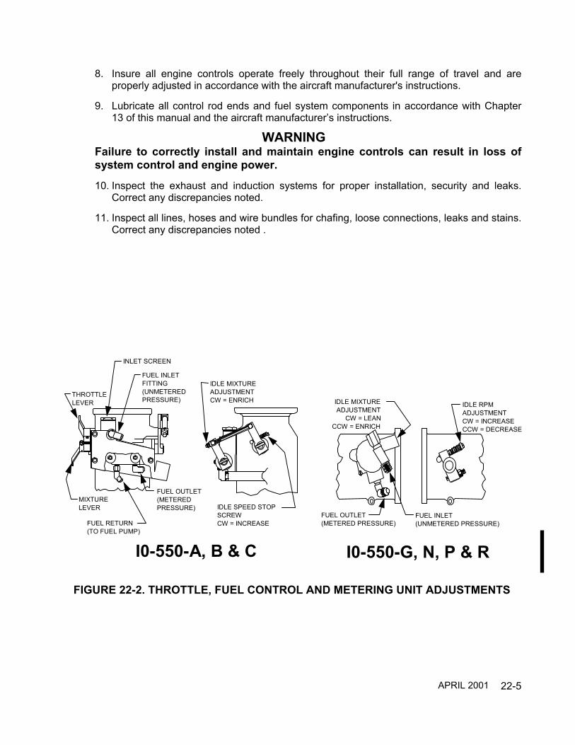
22-5
8. Insure all engine controls operate freely throughout their full range of travel and areproperly adjusted in accordance with the aircraft manufacturer's instructions.
9. Lubricate all control rod ends and fuel system components in accordance with Chapter13 of this manual and the aircraft manufacturer’s instructions.
WARNINGFailure to correctly install and maintain engine controls can result in loss ofsystem control and engine power.
10. Inspect the exhaust and induction systems for proper installation, security and leaks.Correct any discrepancies noted.
11. Inspect all lines, hoses and wire bundles for chafing, loose connections, leaks and stains.Correct any discrepancies noted .
IDLE RPMADJUSTMENTCW = INCREASECCW = DECREASE
IDLE MIXTUREADJUSTMENT
CW = LEANCCW = ENRICH
FUEL INLET(UNMETERED PRESSURE)
FUEL OUTLET(METERED PRESSURE)
I0-550-G, N, P & R
IDLE SPEED STOPSCREWCW = INCREASE
IDLE MIXTUREADJUSTMENTCW = ENRICH
THROTTLELEVER
MIXTURELEVER
FUEL RETURN(TO FUEL PUMP)
FUEL OUTLET(METEREDPRESSURE)
INLET SCREEN
FUEL INLETFITTING(UNMETEREDPRESSURE)
I0-550-A, B & C
FIGURE 22-2. THROTTLE, FUEL CONTROL AND METERING UNIT ADJUSTMENTS
APRIL 2001
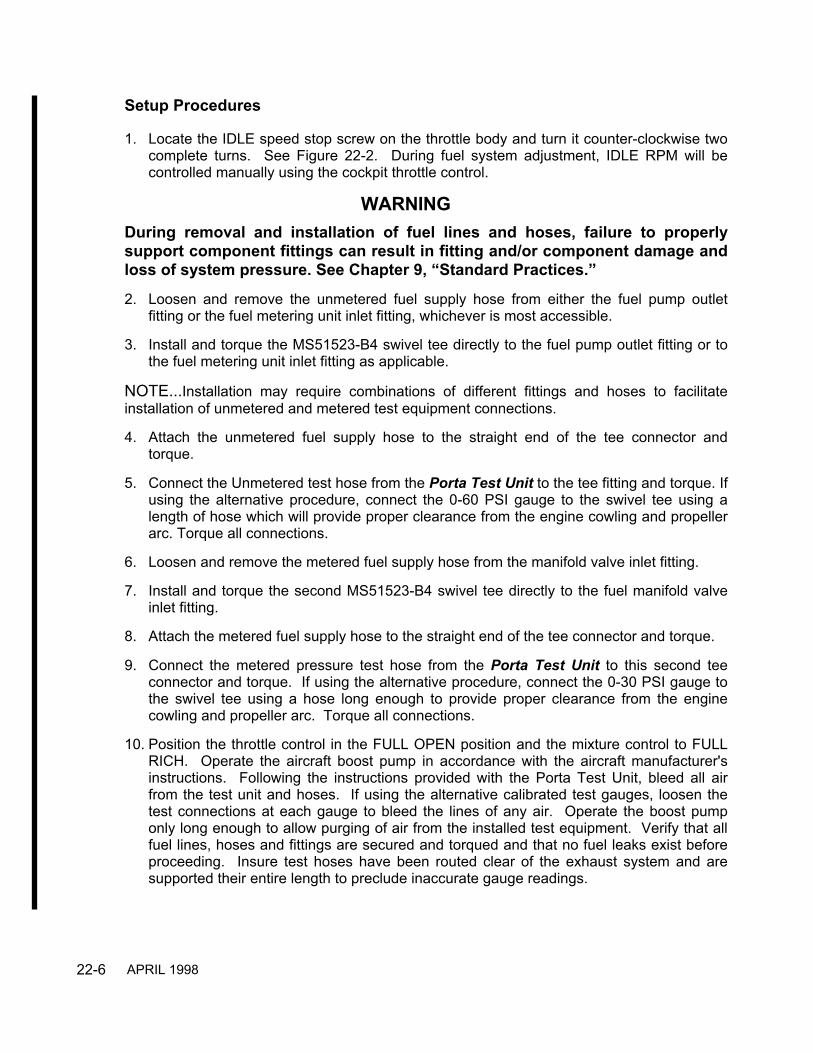
22-6
Setup Procedures
1. Locate the IDLE speed stop screw on the throttle body and turn it counter-clockwise twocomplete turns. See Figure 22-2. During fuel system adjustment, IDLE RPM will becontrolled manually using the cockpit throttle control.
WARNINGDuring removal and installation of fuel lines and hoses, failure to properlysupport component fittings can result in fitting and/or component damage andloss of system pressure. See Chapter 9, “Standard Practices.”
2. Loosen and remove the unmetered fuel supply hose from either the fuel pump outletfitting or the fuel metering unit inlet fitting, whichever is most accessible.
3. Install and torque the MS51523-B4 swivel tee directly to the fuel pump outlet fitting or tothe fuel metering unit inlet fitting as applicable.
NOTE...Installation may require combinations of different fittings and hoses to facilitateinstallation of unmetered and metered test equipment connections.
4. Attach the unmetered fuel supply hose to the straight end of the tee connector andtorque.
5. Connect the Unmetered test hose from the Porta Test Unit to the tee fitting and torque. Ifusing the alternative procedure, connect the 0-60 PSI gauge to the swivel tee using alength of hose which will provide proper clearance from the engine cowling and propellerarc. Torque all connections.
6. Loosen and remove the metered fuel supply hose from the manifold valve inlet fitting.
7. Install and torque the second MS51523-B4 swivel tee directly to the fuel manifold valveinlet fitting.
8. Attach the metered fuel supply hose to the straight end of the tee connector and torque.
9. Connect the metered pressure test hose from the Porta Test Unit to this second teeconnector and torque. If using the alternative procedure, connect the 0-30 PSI gauge tothe swivel tee using a hose long enough to provide proper clearance from the enginecowling and propeller arc. Torque all connections.
10. Position the throttle control in the FULL OPEN position and the mixture control to FULLRICH. Operate the aircraft boost pump in accordance with the aircraft manufacturer'sinstructions. Following the instructions provided with the Porta Test Unit, bleed all airfrom the test unit and hoses. If using the alternative calibrated test gauges, loosen thetest connections at each gauge to bleed the lines of any air. Operate the boost pumponly long enough to allow purging of air from the installed test equipment. Verify that allfuel lines, hoses and fittings are secured and torqued and that no fuel leaks exist beforeproceeding. Insure test hoses have been routed clear of the exhaust system and aresupported their entire length to preclude inaccurate gauge readings.
APRIL 1998

22-7
WARNINGMake certain all fuel has drained from the induction system and properlydisposed of prior to attempting engine start. Failure to do so could causehydraulic lock and subsequent engine failure .11. Install the engine cowling or cooling shroud during ground operation.12. The Operational Test Form on page 22-29 may be reproduced for use in recording
adjustments and test indications. Record the applicable IDLE and FULL POWERadjustment points: RPM, fuel pressure, fuel flows, manifold pressure and fuel/air mixturerise from “Test Operating Limits” in Chapter 5 and Aircraft Maintenance Manual on theoperational test form. See pages 22-11 through 22-28 of this chapter for:
a. Constant Speed Sea Level Performance Curveb. Fuel Flow Vs. Brake Horsepower Performance Curvec. Fuel Flow Vs. Metered Pressure Performance Curve
WARNINGBefore starting the engine insure that the aircraft wheels are chocked andbrakes are set.
13. Prepare the aircraft for ground run and start the engine in accordance with the aircraftmanufacturer's instructions.
14. Advance the throttle to 1500 to 1800 RPM. While monitoring all engine gauges, operatethe engine at this speed until the engine temperatures and pressures have stabilized inthe operational range. Use the operational test form to record the gauge indications.
15. With the mixture control in the FULL RICH position, reduce the throttle to the specifiedIDLE RPM. Record the unmetered pressure indicated on the gauge. Slowly move themixture control toward the IDLE CUT-OFF position and record the maximum RPM rise.Return the mixture control to FULL RICH.
16. Monitoring all engine gauges, slowly advance the throttle control to full rated power forthe engine and allow the engine to stabilize for 15 seconds. Record all engine and testgauge indications. DO NOT ALLOW ENGINE TEMPERATURES TO EXCEED 420°FCYLINDER HEAD TEMPERATURE AND 210°F OIL TEMP. Retard throttle control to800 to 1000 RPM.
NOTE… Engine driven fuel pump output pressures vary with engine RPM. If the engine willnot achieve full power rpm during static ground operational test run use Table 22-1 to correctthe metered fuel pressure specification for the actual rpm achieved.
NOTE…Insure that all engine and aircraft systems are adjusted and functioning properlybefore making any adjustment to the fuel system.17. Compare the recorded IDLE fuel pressure, IDLE RPM fuel/air mixture rise and full power
RPM, manifold pressure (as applicable), unmetered fuel pressure, metered fuel pressureand fuel flow indications with the specified values recorded on the operational test form. Ifall recorded values are within specifications, proceed to paragraph 22 .
APRIL 1998

22-8
18. If any of the recorded readings are not within specifications, the fuel system will requirecomplete adjustment. ALL READINGS MUST BE TAKEN WITH MIXTURE CONTROLIN THE FULL RICH POSITION. Install the engine cowling or cooling shroud during allground operation.
NOTE...Insure that the manifold pressure is adjusted in accordance with the aircraftmanufacturer’s instructions.
WARNINGMake all adjustments with the engine stopped and the ignition and masterswitches in the off position !
19. To adjust the IDLE RPM unmetered pump pressure, loosen the lock nut on the lowpressure relief valve. See Figure 22-3. Turning the adjustment clockwise (CW) willincrease pressure and counterclockwise (CCW) will decrease pressure. Operate theengine at 1500 - 1800 RPM for 15 seconds after each adjustment, then retard the throttleto the specified IDLE RPM. Repeat this step until pressure is within specified limits.
NOTE...It is desirable to set IDLE RPM unmetered pump pressure to the minimum limit.With properly adjusted fuel/air mixture, this will provide a slight fuel enrichment during partthrottle operations .
20. With engine operating at the specified IDLE RPM and unmetered fuel pressure, slowlymove the mixture control from the FULL RICH position toward IDLE CUT-OFF to check
FIGURE 22-3. FUEL PUMP ADJUSTMENTS
APRIL 2001

22-9
fuel/air mixture. A rise of 25 to 50 RPM should be obtained. An RPM change greaterthan 50 indicates the mixture is too rich and a change that is less than 25 indicates themixture is too lean. Any mixture conditions that are too rich or too lean will be adjustedas follows:
a) Adjust idle mixture in accordance with Figure 22-2, “Throttle and Fuel MeteringAdjustments.”
b) Perform an IDLE fuel/air mixture check and observe RPM rise. If the RPM rise is notwithin specifications, advance the throttle control to 1500 - 1800 RPM for 15 secondsafter each adjustment to clear the engine. Retard the throttle control to IDLE RPMand repeat mixture check. Make the necessary adjustment. Repeat this procedureuntil the specified RPM rise is achieved.
c) Recheck IDLE RPM unmetered pump pressure. If pressure in not within limits,repeat Steps 18, 19, 19-a and 19-b before continuing.
21. See Chapter 5 “Test Operating Limits.” Adjust the full power fuel flow to the specifiedvalue by turning the adjustable orifice screw clockwise to increase fuel flow andcounterclockwise to decrease fuel flow. See Figure 22-3 for fuel pump adjustments.
22. When full power fuel flow has been adjusted to the specified values, recheck the IDLERPM unmetered fuel pressure and fuel/air mixture. If any values are not within specifiedlimits, repeat the adjustment procedures.
23. With the fuel system set to the specified pressure and flow values, set the IDLE RPM tothe specified value by turning the Idle Speed Stop screw clockwise to increase RPM andcounterclockwise to decrease RPM. See Figure 22-2 and Chapter 5, “Test OperatingLimits.”
Post Setup Procedures
1. Insure that the master switch, ignition switch and fuel selector are in the off position.2. Remove the engine cowling or cooling shroud in accordance with the aircraft
manufacturer's instructions. Remove all test gauges, fittings and hoses that wereinstalled for fuel system setup. Reconnect all fuel hoses to their original locations,support and torque all fittings to the specified value.
3. Perform a complete fuel system leak check in accordance with the aircraft manufacturer’sinstructions. Correct any discrepancies noted.
4. Install engine cowling or cooling shroud in accordance with the aircraft manufacturer'sinstructions.
5. Perform a complete operational ground run-up and verify that all fuel system performancespecifications are achieved .
6. Repeat the setup and adjustments as required until the fuel injection system isperforming within the published specification for the aircraft and engine .
Table 22-1. Compensation Table For Static Ground Setup
APRIL 1998

22-10
Metered Pressure Vs. RPM @ 70°F Fuel Temperature
Static Engine RPM Correction FactorCorrected Metered
Pressure(Metered Pressure
x Correction Factor)
Rated RPM 1
-20 0.991
-40 0.982
-60 0.973
-80 0.964
-100 0.955
-120 0.946
NOTE: All values are approximate. Variations may be noticed due to engine andinstallation specific influences.
Example: I0-550-B, Maximum Rated RPM = 2700Metered Fuel Pressure Limits = 16.5 - 18.4
If maximum static engine RPM = 2640, (-60 RPM) use Correction Factor 0.973Metered Fuel Pressure Limits x Correction Factor = Corrected Metered
Pressure Limits16.5 x 0.973 = 16.0545 (Minimum Metered Pressure Limit) @ 2640 RPM18.4 x 0.973 = 17.9032 (Maximum Metered Pressure Limit) @ 2640 RPM
APRIL 1998

22-11
300
280
260
240
220
200
180
160
140
120
100
80
17 18 19 20 21 22 23 24 25 26 27 28 29 30
FULL THROTTLE HORSEPOWERAT ZERO RAM
2700 RPM
2500 RPM
2300 RPM
2100 RPM
1900 RPM
BR
AK
E H
OR
SEPO
WER
ABSOLUTE DRY MANIFOLD PRESSURE IN. HG.
300
280
260
240
220
200
180
160
140
120
100
80
BR
AK
E H
OR
SEPO
WER
FIGURE 22-4. SEA LEVEL PERFORMANCE IO-550-A
APRIL 1998

22-12
140
160
180
200
220
240
260
280
300
160
150
140
130
120
110
100
90 80 70 60 5045
%
78%
75%
65%
55%
Peak
EG
T M
ixtu
re
Bes
t Eco
nom
y M
ixtu
re
25 -
50o F
Lea
n of
Pea
kEG
T
Bes
t Pow
erM
ixtu
re
FULL
RIC
H LI
MIT
S
IO-5
50-A
FU
EL F
LOW
VS.
BR
AK
E H
OR
SEPO
WER
BR
AK
E H
OR
SEPO
WER
FUEL FLOW LBS./HR.
FIGURE 22-5. FUEL FLOW VS. OBSERVED BRAKE HORSEPOWER IO-550-A
APRIL 1998

22-13
2040
6080
100
120
140
160
180
24 22 20 18 16 14 12 10 8 6 4
24 22 20 18 16 14 12 10 8 6 4
IO-5
50-A
MET
ERED
FU
EL P
RES
SUR
E VS
. FU
EL F
LOW
FUEL
FLO
W L
BS.
/ H
R.
METERED FUEL PRESSURE (PSI)
Not
e: t
his
data
is a
ppro
xim
ate
with
Fu
el p
ress
ure
gaug
e at
sam
e el
evat
ion
As m
anifo
ld v
alve
and
with
out i
nflu
ence
of d
iffer
entia
l fue
l hea
d in
gau
ge li
ne.
Nom
inal
tole
ranc
e +
.3 p
si
FIGURE 22-6. FUEL FLOW VS. METERED PRESSURE IO-550-AAPRIL 1998

22-14
160
150
140
130
120
110
100
90
Pres
sure
Alti
tude
(fee
t)
Alti
tude
Lea
ning
Cha
rt -
IO-5
50-A
Ful
l Ric
h, 2
700
RPM
Fuel Flow (pph)
010
0020
0030
0040
0050
0060
0070
0080
0090
0010
000
1100
012
000
1300
014
000
FIGURE 22-7. AUTO LEANING SCHEDULE IO-550-A
APRIL 1998

22-15
300
280
260
240
220
200
180
160
140
120
100
80
17 18 19 20 21 22 23 24 25 26 27 28 29 30
FULL THROTTLE HORSEPOWERAT ZERO RAM
2700 RPM
2500 RPM
2300 RPM
2100 RPM
1900 RPM
BR
AK
E H
OR
SEPO
WER
ABSOLUTE DRY MANIFOLD PRESSURE IN. HG.
300
280
260
240
220
200
180
160
140
120
100
80
BR
AK
E H
OR
SEPO
WER
FIGURE 22-8. SEA LEVEL PERFORMANCE IO-550-B
APRIL 1998
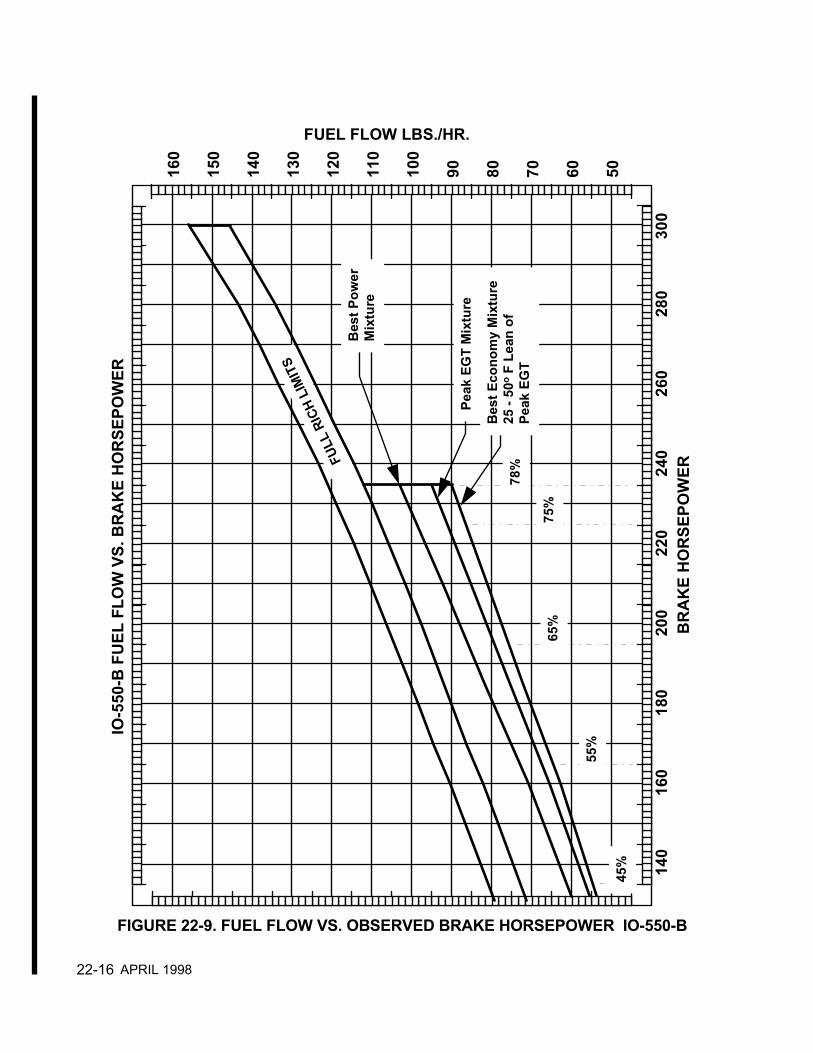
22-16
140
160
180
200
220
240
260
280
300
160
150
140
130
120
110
100
90 80 70 60 50
78%
75%
65%
55%
45%
Peak
EG
T M
ixtu
re
Bes
t Eco
nom
y M
ixtu
re
25 -
50o F
Lea
n of
Peak
EG
T
Bes
t Pow
erM
ixtu
re
FULL
RIC
H LI
MIT
S
IO-5
50-B
FU
EL F
LOW
VS.
BR
AK
E H
OR
SEPO
WER
BR
AK
E H
OR
SEPO
WER
FUEL FLOW LBS./HR.
FIGURE 22-9. FUEL FLOW VS. OBSERVED BRAKE HORSEPOWER IO-550-B
APRIL 1998
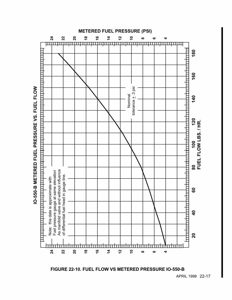
22-17
2040
6080
100
120
140
160
180
24 22 20 18 16 14 12 10 8 6 4
24 22 20 18 16 14 12 10 8 6 4
IO-5
50-B
MET
ERED
FU
EL P
RES
SUR
E VS
. FU
EL F
LOW
FUEL
FLO
W L
BS.
/ H
R.
METERED FUEL PRESSURE (PSI)
Not
e: t
his
data
is a
ppro
xim
ate
with
Fu
el p
ress
ure
gaug
e at
sam
e el
evat
ion
As m
anifo
ld v
alve
and
with
out i
nflu
ence
of d
iffer
entia
l fue
l hea
d in
gau
ge li
ne.
Nom
inal
tole
ranc
e +
.3 p
si
FIGURE 22-10. FUEL FLOW VS METERED PRESSURE IO-550-BAPRIL 1998
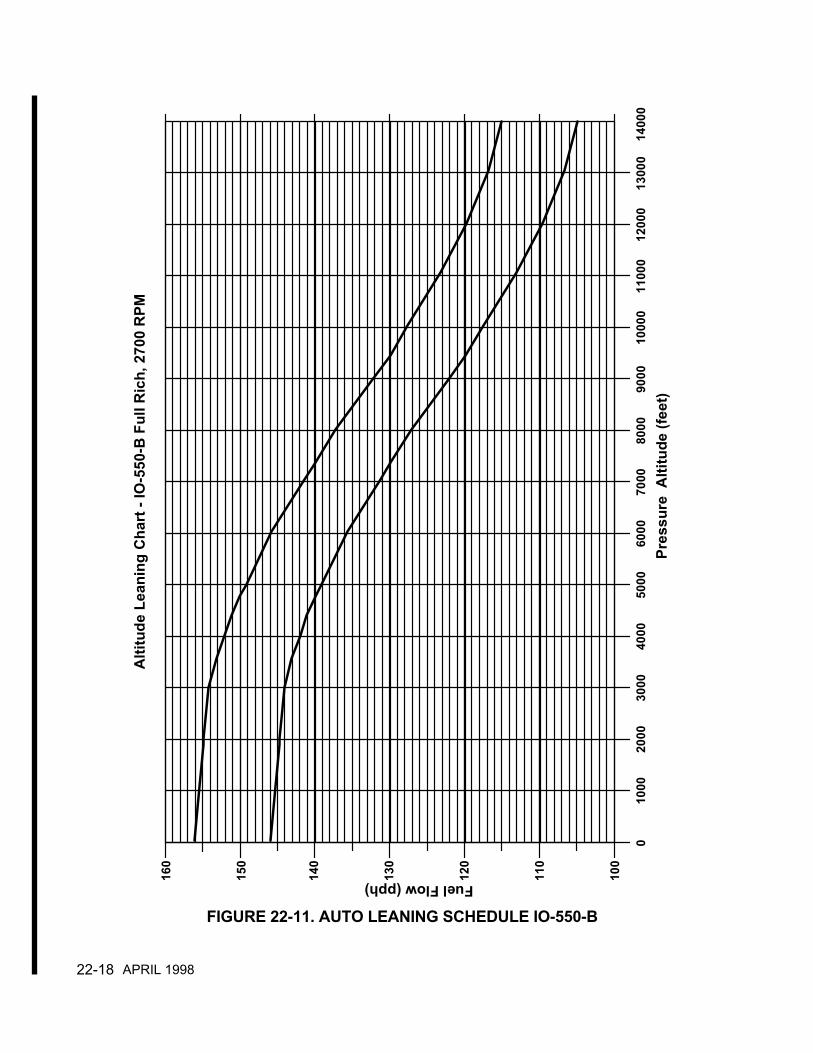
22-18
160
150
140
130
120
110
100
Alti
tude
Lea
ning
Cha
rt -
IO-5
50-B
Ful
l Ric
h, 2
700
RPM
Pres
sure
Alti
tude
(fee
t)
Fuel Flow (pph)
010
0020
0030
0040
0050
0060
0070
0080
0090
0010
000
1100
012
000
1300
014
000
FIGURE 22-11. AUTO LEANING SCHEDULE IO-550-B
APRIL 1998

22-19
300
280
260
240
220
200
180
160
140
120
100
80
17 18 19 20 21 22 23 24 25 26 27 28 29 30
FULL THROTTLE HORSEPOWERAT ZERO RAM
2700 RPM
2500 RPM
2300 RPM
2100 RPM
1900 RPM
BR
AK
E H
OR
SEPO
WER
ABSOLUTE DRY MANIFOLD PRESSURE IN. HG.
300
280
260
240
220
200
180
160
140
120
100
80
BR
AK
E H
OR
SEPO
WER
FIGURE 22-12. SEA LEVEL PERFORMANCE IO-550-C
APRIL 1998
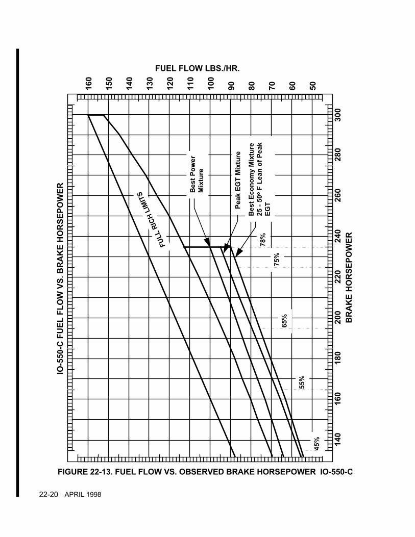
22-20
140
160
180
200
220
240
260
280
300
160
150
140
130
120
110
100
90 80 70 60 50
78%
75%
65%
55%
45%
Peak
EG
T M
ixtu
re
Bes
t Eco
nom
y M
ixtu
re
25 -
50o F
Lea
n of
Pea
kEG
T
Bes
t Pow
erM
ixtu
re
FULL
RIC
H LI
MIT
S
IO-5
50-C
FU
EL F
LOW
VS.
BR
AK
E H
OR
SEPO
WER
BR
AK
E H
OR
SEPO
WER
FUEL FLOW LBS./HR.
FIGURE 22-13. FUEL FLOW VS. OBSERVED BRAKE HORSEPOWER IO-550-C
APRIL 1998

22-21
2040
6080
100
120
140
160
180
24 22 20 18 16 14 12 10 8 6 4
24 22 20 18 16 14 12 10 8 6 4
IO-5
50-C
MET
ERED
FU
EL P
RES
SUR
E VS
. FU
EL F
LOW
FUEL
FLO
W L
BS.
/ H
R.
METERED FUEL PRESSURE (PSI)
Not
e: t
his
data
is a
ppro
xim
ate
with
Fu
el p
ress
ure
gaug
e at
sam
e el
evat
ion
As m
anifo
ld v
alve
and
with
out i
nflu
ence
of d
iffer
entia
l fue
l hea
d in
gau
ge li
ne.
Nom
inal
tole
ranc
e +
.3 p
si
FIGURE 22-14. FUEL FLOW VS METERED PRESSURE IO-550-CAPRIL 1998
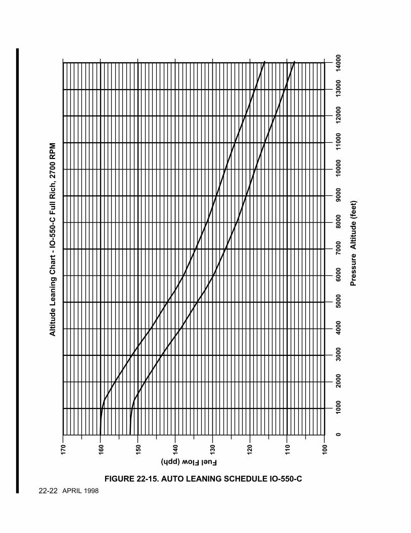
22-22
170
160
150
140
130
120
110
100
Pres
sure
Alti
tude
(fee
t)
Alti
tude
Lea
ning
Cha
rt -
IO-5
50-C
Ful
l Ric
h, 2
700
RPM
Fuel Flow (pph)
010
0020
0030
0040
0050
0060
0070
0080
0090
0010
000
1100
012
000
1300
014
000
FIGURE 22-15. AUTO LEANING SCHEDULE IO-550-CAPRIL 1998

22-23
280
260
240
220
200
180
160
140
120
100
80
60
17 18 19 20 21 22 23 24 25 26 27 28 29 30
FULL THROTTLE HORSEPOWERAT ZERO RAM
2500 RPM
2300 RPM
2100 RPM
1900 RPM
1700 RPM
BR
AK
E H
OR
SEPO
WER
ABSOLUTE DRY MANIFOLD PRESSURE IN. HG.
280
260
240
220
200
180
160
140
120
100
80
60
BR
AK
E H
OR
SEPO
WER
FIGURE 22-16. CONSTANT SPEED SEA LEVEL PERFORMANCE IO-550-G
APRIL 1998

22-24
140
160
180
200
220
240
260
280
300
130
120
110
100
90 80 70 60 50 40
85%
75%
65%
Peak
EG
T
Min
imum
BSF
C50
o Lea
n of
Pea
k
Bes
t Pow
er
IO-5
50-G
FU
EL F
LOW
VS.
BR
AK
E H
OR
SEPO
WER
BR
AK
E H
OR
SEPO
WER
FUEL FLOW LBS./HR.
FULL
RIC
H LI
MIT
S25
o Ric
h of
Pea
k
FIGURE 22-17. FUEL FLOW VS. OBSERVED BRAKE HORSEPOWER IO-550-G
APRIL 1998

22-25
2040
6080
100
120
140
160
24 22 20 18 16 14 12 10 8 6 4
24 22 20 18 16 14 12 10 8 6 4
IO-5
50-G
MET
ERED
FU
EL P
RES
SUR
E VS
. FU
EL F
LOW
FUEL
FLO
W L
BS.
/ H
R.
METERED FUEL PRESSURE (PSI)
Not
e: t
his
data
is a
ppro
xim
ate
with
Fu
el p
ress
ure
gaug
e at
sam
e el
evat
ion
As m
anifo
ld v
alve
and
with
out i
nflu
ence
of d
iffer
entia
l fue
l hea
d in
gau
ge li
ne.
Nom
inal
tole
ranc
e +
.25
psi
FIGURE 22-18. FUEL FLOW VS METERED PRESSURE IO-550-GAPRIL 1998
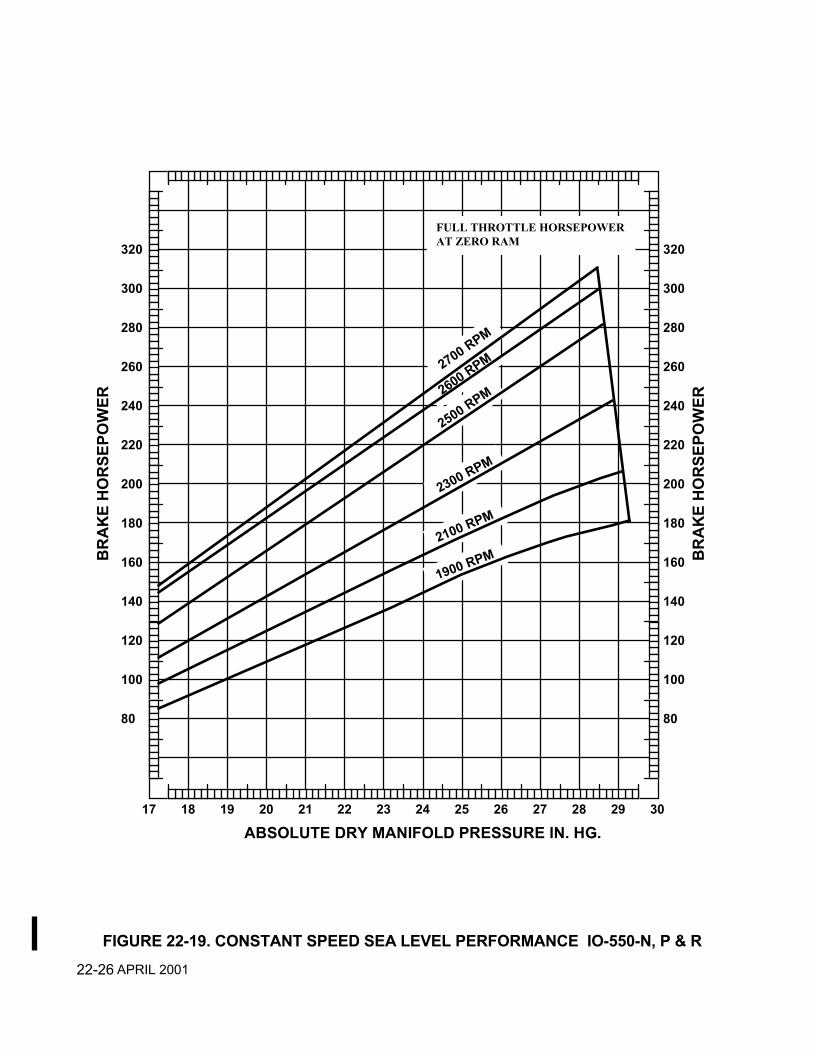
22-26
320
300
280
260
240
220
200
180
160
140
120
100
80
17 18 19 20 21 22 23 24 25 26 27 28 29 30
FULL THROTTLE HORSEPOWERAT ZERO RAM
2700 RPM
2600 RPM
2500 RPM
2300 RPM
2100 RPM
1900 RPMBR
AK
E H
OR
SEPO
WER
ABSOLUTE DRY MANIFOLD PRESSURE IN. HG.
320
300
280
260
240
220
200
180
160
140
120
100
80B
RA
KE
HO
RSE
POW
ER
FIGURE 22-19. CONSTANT SPEED SEA LEVEL PERFORMANCE IO-550-N, P & RAPRIL 2001

22-27
150
170
190
210
230
250
270
290
310
160
150
140
130
120
110
100
90 80 70 60 50
FULL
RIC
H LI
MIT
S
IO-5
50-N
FU
EL F
LOW
VS.
BR
AK
E H
OR
SEPO
WER
BR
AK
E H
OR
SEPO
WER
FUEL FLOW LBS./HR.
75%
65%
Bes
t Pow
er
55%
Bes
t Eco
nom
y
FIGURE 22-20. FUEL FLOW VS. OBSERVED BRAKE HORSEPOWER IO-550-N, P & R
APRIL 2001

22-28
2040
6080
100
120
140
160
24 22 20 18 16 14 12 10 8 6 4
24 22 20 18 16 14 12 10 8 6 4
IO-5
50-N
MET
ERED
FU
EL P
RES
SUR
E VS
. FU
EL F
LOW
FUEL
FLO
W L
BS.
/ H
R.
METERED FUEL PRESSURE (PSI)
Not
e: t
his
data
is a
ppro
xim
ate
with
Fu
el p
ress
ure
gaug
e at
sam
e el
evat
ion
As m
anifo
ld v
alve
and
with
out i
nflu
ence
of d
iffer
entia
l fue
l hea
d in
gau
ge li
ne.
Nom
inal
tole
ranc
e +
.25
psi
FIGURE 22-21. FUEL FLOW VS METERED PRESSURE IO-550-N, P & RAPRIL 2001
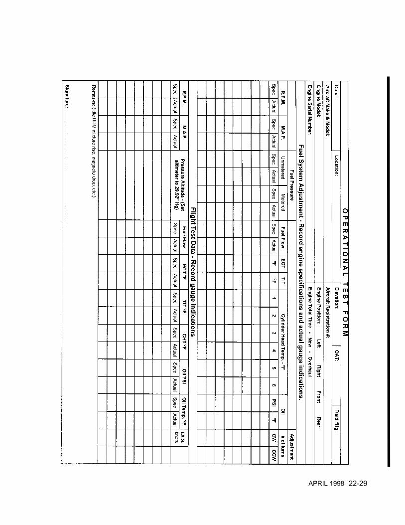
22-29APRIL 1998

22-30
22-4 TEST FLIGHTRefer to the aircraft manufacturer’s or Supplemental Type Certificate (STC) holdersPOH/AFM for specific operational information.NOTE…I0-550-A, B & C engines with altitude compensating fuel pumps require the autolean operation inspection below during test flight.Ambient air and engine operating temperatures are of major concern during this test flight. Do anormal pre-flight run-up in accordance with the Airplane Flight Manual. Conduct a normal take-off with full power and monitor the fuel flow, RPM, oil pressure, coolant temperatures and oiltemperatures. Reduce to climb power in accordance with the Airplane Flight Manual. Themanual mixture control should be set in the full rich position for all operations except leaning forfield elevation and leaning to maintain smoothness during climb and leaning for cruiseeconomy. Leaning operations must be performed in accordance with the Airplane FlightManual.
NOTE…New, rebuilt and overhauled engines or engines that have had new or repairedcylinders installed must be flown in accordance with the following procedure for the first twohours of operation.Level flight cruise should be at 75% power with best power or richer mixture for the first hour ofoperation. The second hour power settings should alternate between 65% and 75% power withthe appropriate best power mixture settings. The best power mixture setting is 100° to 125° richof peak turbine inlet temperature. Engine controls or aircraft attitude should be adjusted asrequired to maintain engine temperatures and pressures within specifications.Descent from high altitude should be accomplished at low cruise power settings. Duringdescent engine pressures and temperatures must be carefully monitored. Avoid long descentswith cruise RPM and manifold pressure below 18" Hg.
CAUTION…Rapid descents at high RPM and low manifold pressure are to be avoided.
During descent monitor coolant and oil temperatures maintaining above the minimumrecommended operating range .
NOTE…Avoid long descents at low manifold pressure, which can result in excessive enginecooling. Satisfactory engine acceleration may not occur when power is applied.Any discrepancies detected during test flight must be corrected and the aircraft again test flownprior to approval of engine for return to service. The appropriate logbook entries must be madein accordance with Part 43 of the Federal Aviation Regulations (FAR) before the engine can bereturned to service.
AUTO LEAN OPERATIONIn addition to the above I0-550-A, B & C engines with altitude compensating fuel pumpsrequire a flight test every 100 hours or annual inspection and anytime an adjustment is madeto the fuel injection system to insure proper operation of the fuel pump auto leaning feature.
1. Tables 22-2, 22-3, 22-4 and the Auto Leaning Charts, Figures 22-7, 22-11, 22-15 providefuel flow vs. pressure altitude specifications .
2. Insure the accuracy of aircraft fuel flow gauge and tachometer have been verified. Thesegauges must be accurate or the data recorded during flight test will not be valid.
APRIL 2001

22-31
3. Locate the correct table and auto leaning chart for the aircraft and engine. On theoperational test form provided in this Service Information Directive, record all pressurealtitudes and corresponding minimum and maximum fuel flows as specified.
4. In accordance with the aircraft manufacturer’s instructions perform a complete pre-flightinspection, engine start and ground run up.
5. Set the aircraft altimeter to 29.92 inches Hg.
6. In accordance with the aircraft manufacturer’s instructions make a normal take-off.
7. Climb must be accomplished at full throttle, FULL RICH mixture and 2700 RPM at thebest rate of climb airspeed or higher for the aircraft.
8. Using the aircraft fuel flow gauge and altimeter record the fuel flows at all pressurealtitudes specified.
9. Compare the recorded fuel flows with the specified fuel flows for all pressure altitudes. Iffuel flows are within the minimum and maximum limits at all altitudes no adjustments arerequired.
10. If the fuel flows are not within the specified limits at all pressure altitudes the fuel injectionsystem auto leaning schedule will require adjustment.
TABLE 22-2. ALTITUDE FUEL SCHEDULE
IO-550-A ENGINEFULL OPEN THROTTLE, FULL RICH MIXTURE
300 BHP @ 2700 RPMPressure Altitude(Set Altimeter at
29.92 in. Hg.)
Fuel Flow(lbs/hr)
Min. Max.
Fuel Flow(gals/hr)
Min. Max.
Metered FuelPressure PSIDMin. Max.
Sea Level 142 150 24.2 25.6 16.5 17.21000 141 149 24.0 25.4 16.3 17.12,000 138 146 23.5 24.9 15.9 16.63000 133 141 22.6 24.0 15.1 15.74,000 128 136 21.8 23.2 14.3 14.95000 123 131 21.0 22.3 13.6 14.16,000 120 128 20.4 21.8 13.2 13.78,000 113 121 19.2 20.6 12.3 12.7
10,000 108 116 18.4 19.8 11.6 12.112,000 103 111 17.5 18.9 11.0 11.414,000 98 106 16.7 18.1 10.4 10.7Gasoline = 5.87 lbs per gallon @ 70° F.
APRIL 1998

22-32
TABLE 22-3. ALTITUDE FUEL SCHEDULE
IO-550-B ENGINEFULL OPEN THROTTLE, FULL RICH MIXTURE
300 BHP @ 2700 RPMPressure Altitude(Set Altimeter at
29.92 in. Hg.)
Fuel Flow(lbs/hr)
Min. Max.
Fuel Flow(gals/hr)
Min. Max.
Metered FuelPressure PSID
Min. Max.Sea Level 146 156 24.9 26.6 17.2 18.3
1000 145.5 155.5 24.8 26.5 17.1 18.22,000 145 155 24.7 26.4 17.0 18.13000 144 154 24.5 26.3 16.9 17.94,000 142 152 24.2 25.9 16.5 17.55000 139 149 23.7 25.4 16.1 17.06,000 135.5 145.5 23.1 24.8 15.5 16.58,000 127 137 21.6 23.3 14.2 15.1
10,000 117 127 19.9 21.6 12.8 13.612,000 110 120 18.7 20.4 11.9 12.614,000 105 115 17.9 19.6 11.3 11.9
Gasoline = 5.87 lbs per gallon @ 70° F.
TABLE 22-4. ALTITUDE FUEL SCHEDULE
IO-550-C ENGINEFULL OPEN THROTTLE, FULL RICH MIXTURE
300 BHP @ 2700 RPMPressure Altitude(Set Altimeter at
29.92 in. Hg.)
Fuel Flow(lbs/hr)
Min. Max.
Fuel Flow(gals/hr)
Min. Max.
Metered FuelPressure PSID
Min. Max.Sea Level 152 160 25.9 27.2 18.2 18.9
1000 151 159 25.7 27.1 18.0 18.72,000 148 156 25.2 26.6 17.5 18.23000 143 151 24.4 25.7 16.7 17.44,000 138 146 23.5 24.9 15.9 16.55000 134 142 22.8 24.2 15.3 15.96,000 130 138 22.1 23.5 14.7 15.38,000 123 131 21.0 22.3 13.6 14.1
10,000 118 126 20.1 21.5 12.9 13.412,000 113 121 19.3 20.6 12.3 12.714,000 108 116 18.4 19.8 11.7 12.1
Gasoline = 5.87 lbs per gallon @ 70° F.
APRIL 1998

22-33
ADJUSTMENT PROCEDURES:Fuel Pump Auto Leaning Schedule
NOTE...On IO-550-A and C model engines do not attempt to adjust the auto leaning scheduleif the aircraft is at a field with a pressure altitude greater than 1000 feet.
On IO-550-B model engines do not attempt to adjust the auto leaning schedule if the aircraftis at a field with a pressure altitude greater than 3000 feet.
Refer to Fuel System Adjustment (Setup Procedures) of this chapter for installation of therequired test equipment.
1. If not previously accomplished, adjust the engine fuel injection system in accordance withFuel System Adjustment of this chapter using the appropriate table for the engine andaircraft.
2. Adjustments to the engine driven fuel pump variable orifice (aneroid, see Figure 22-3) willresult in a change to the auto leaning schedule. One complete revolution of the aneroidadjustment will increase or decrease the auto leaning schedule approximately 1000 feet.
3. Refer to Figures 22-7, 22-11, 22-15 as applicable. The variable orifice (aneroid)adjustment will move you horizontally across the chart. The adjustable orifice will moveyou vertically.
4. Adjustments to the variable orifice (aneroid) will affect the FULL POWER unmetered fuelpressures (adjustable orifice), metered pressures and fuel flows. It is important tomaintain the balance between these adjustments in order to achieve the specified fuelsystem parameters.
CAUTION…Exercise caution when adjustments to the aneroid are accomplished. Theaneroid stem has an extra fine thread and over torqueing of the lock nut will damage eitherthe stem or housing threads.
NOTE...It will be necessary to cut and remove the safety wire and manufacturer’s seal fromthe variable orifice adjustment. Cut the safety wire as close to the variable orifice stem aspossible. This will provide a pig tail for the fuel pump through bolts. It is not necessary to re-safety the aneroid after adjustments have been completed.
5. By reviewing the data recorded on the operational test flight form we can determine if theauto leaning schedule is above or below the specified limits at the various pressurealtitudes.
6. Adjustment of the variable orifice (aneroid) clockwise will decrease the altitude (movehorizontally to the left on the chart) while counter-clockwise adjustments will increase thealtitude (move horizontally to the right on the chart) at a given pressure altitude.
7. As an example, looking at Figure 22-11 (IO-550-B engine) at a pressure altitude of 4000feet the recorded fuel flow was 140 PPH (point A) The fuel flow specified for this pressurealtitude is 142 PPH to 152 PPH. The recorded fuel flow of 140 PPH would be correct ifwe were between 5000 feet and 7000 feet. To achieve the specified fuel flow versespressure altitude we must adjust the variable orifice out. Adjustment of the variable orifice(aneroid) two complete revolutions will move point A two thousand feet to the right to6000 feet.
8. After making any adjustment to the variable orifice, torque the lock nut to 25 - 30 inchpounds.
APRIL 2001

22-34
9. Perform a complete ground run up and verify that unmetered and metered pressures andfuel flows are within the limits specified in appropriate table for the pressure altitude. Ifthese parameters are not within the limits specified make adjustments in accordance with“Fuel System Adjustment” of this chapter to achieve the specified values.
NOTE...The adjustable orifice tapered needle may be damaged if forced against it’s seat.The adjustment should move freely. Do not continue adjustments if rotational resistanceincreases suddenly.
10. Once the adjustments are completed, remove the test equipment in accordance with“Fuel System Adjustment” (Post Setup Procedures) of this chapter.
11. Perform a flight test in accordance with “Test Flight. ”
Repeat these procedures until the engines fuel injection system meets all publishedspecifications.
APRIL 1998