permas - intes...damping, and direct input of damping matrices (also in modal space). in frequency...
TRANSCRIPT

Version 15
PERMAS
E

1984: Start of software industrialization and new developments in optimization, acoustics, and reliability
1989: Start of full re-design of software for higher speed of development and Nastran compatibility
1993: PERMAS Version 5 available, the new software basis for further development
2005: Start of VisPER development, a new graphical user interface for PERMAS
2008: VisPER Version 1
2014: PERMAS Version 15 and VisPER Version 4
ASKA
Visual PERMAS
INTES is a privately held and independent enterprise for Finite Element Technology (FE Technology) with offices in Stuttgart, Paris und Tokyo.
For all of its customers, INTES wants to be a competent partner in all aspects of FE Technology. Above all, satisfaction of the customers with all the software and services is of prime importance to the company.
INTES
INTES
INTES offers the FE software PERMAS (including VisPER as graphical user interface), related software developments, training courses, consulting and simulation services.
The expertise in FE Technology is based on long-term numerical and graphical software development of FE methods and on many industrial applications of these methods.
INTES was founded in 1984 as a spin-off of Stuttgart University.
2
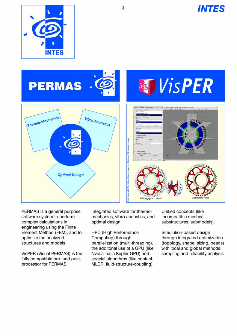
Thermo-Mechanics Vibro-Acoustics
Optimal Design
Füllungsgrad >70% Geglättete Hülle
Mit
fre
un
dlic
her
Gen
eh
mig
un
g v
on
Daim
ler
Nu
tzfa
hrz
eu
ge
Unified concepts (like incompatible meshes, substructures, submodels).
Simulation-based design through integrated optimization (topology, shape, sizing, beads) with local and global methods, sampling and reliability analysis.
PERMAS is a general purpose software system to perform complex calculations in engineering using the Finite Element Method (FEM), and to optimize the analyzed structures and models.
VisPER (Visual PERMAS) is the fully compatible pre- and post-processor for PERMAS.
INTES
INTES
Integrated software for thermo-mechanics, vibro-acoustics, and optimal design.
HPC (High Performance Computing) through parallelization (multi-threading), the additonal use of a GPU (like Nvidia Tesla Kepler GPU) and special algorithms (like contact, MLDR, fluid-structure-coupling).
3

INTES
Thermo-Mechanics
This group of modules comprises functionalities for heat transfer analysis (linear and nonlinear, steady-state and transient) to calculate temperature elds. It also comprises contact analysis and linear and nonlinear static analysis with geometric and material nonlinearities. Moreover, linear and nonlinear buckling analysis also belongs to this module group, where the nonlinear buckling is covered by nonlinear static analysis. Previously calculated temperature elds can be directly used in subsequent static analysis.
Radiation with heat exchange of a cooling element
Contact is a nonlinear boundary condition, which can be coupled with other linear conditions as well as with nonlinearities. At the same time, the contact can be calculated between different bodies, between a body and ground, but also when self contact occurs.
The contact analysis can be performed with or without friction, where isotropic or orthotropic sticking and sliding friction is applied following Coulomb's law of friction.
The contact analysis is most efcient, when no friction has to be taken into account.The linear buckling analysis is a
classical method to study shell and beam structures. It can be used also after a nonlinear static analysis in order to detect additional bifurcation points.
Linear buckling of acylindrical composite shell
V8 engine by courtesy of fpt Motorenforschung AG, Arbon, Switzerland
Contact can be calculated between compatibly and incompatibly meshed parts. In both cases, the resulting contact pressure is available.
4

Nonlinear material behaviour can use different constitutive models: nonlinear elastic material, elastic-plastic material (von Mises, Tresca, Drucker-Prager, Mohr-Coulomb, cast iron), simple visco-plastic material, creep. At the same time, the material can be temperature-dependent. In case of plasticity isotropic or kinematic hardening can be taken into account (the latter also as nonlinear kinematic hardening). A user-dened material is possible.
For large models and local nonlinear effects, substructuring and submodeling can be used in nonlinear analysis.
Meshing of two gears
By updating the contact geometry, large sliding displacements can be calculated. Together with geometrical nonlinear effects, large rotations are carried out.
Bolt model with thread coupling
Nonlinear gaskets are modeled by special gasket elements, which are fully handled by contact analysis.
Purely force-guided contacts are also possible with larger initial gap widths.
An obtained contact status can be re-used in a subsequent variant analysis. This has the potential to reduce the run time of the variant analysis signicantly.
To perform a subsequent dynamic or heat transfer analysis, the achieved contact status can be frozen, where a pressure dependent coupling is supported.
Bolt pretension is also made by contact. The coupling of screw and mating thread takes place at the thread area, while the bolt and the bolt hole remain perfectly cylindrical. By doing so, the radial widening of the bolt hole and the twist of the bolt can be modeled by a ank angle and the pitch of the thread without modeling the thread itself.
Self-contact of a bellow
INTES
Thermo-Mechanics
5

Vibro-Acoustics
INTES
Structure-borne and air-borne noise with sound transition at a vehicle
This group of modules comprises functionalities in modal space with real and complex eigenvalue analyses, dynamic condensation, and response analysis in frequency and time domain (also steady-state) for structural dynamics. Additionally, spectral and random response analysis are available. Direct solutions for response analysis in frequency and time domain are available, too.
For both a Fluid only and the coupled Fluid-Structure-Acoustics, real eigenvalue analysis, dynamic condensation, and response analysis in frequency and time domain are supported in modal space. A direct solution for the response analysis in frequency domain is also available.
In a real eigenvalue analysis of a structure the elastic stiffness can be extended by geometric stiffness and pressure stiffness, if needed. In rotor dynamics, centrifugal stiffness or convective stiffness can be taken into account as the case may be calculated in a co-rotating or inertial reference system.
The real eigenvalue analysis in coupled uid-structure acoustics results in eigenmodes, which consist of displacements for the structure and a corresponding pressure eld for the uid.
For very large models with a high number of modes to be calculated, a special eigenvalue solver using the MLDR method (Multi-Level Dynamic Reduction) provides an extraordinary efcient procedure.
The complex eigenvalue analysis is based on real eigenvalues and mode shapes. For rotating structures, a Campbell diagram for an arbitrary number of rotating speeds can be generated in one single run.
Forward and backward whirl of complex eigenmode shapes
for a rotor in a non-rotating housing (by courtesy of
MAHLE Behr GmbH & Co. KG)
The modeling of a uid is using volume elements and the connection to the structure is using coupling elements. For the boundaries of surrounding uids, radiation boundary condition elements and semi-innite elements are available.
6

Active damping of vibrations of a composite box girder
For complex position and velocity control (like for machine tools) additional control elements are on hand.
2-axes control of turning machine
In case of coupled uid-structure acoustics, a structure with enclosed uid can be condensated in a way that no pressure degrees of freedom are present in the condensated system (so-called dry condensation).
In dynamic brake analysis the contact status between brake pad and disc can be frozen for a subsequent real and complex eigenvalue analysis to identify instabilities indicating brake squeal. An additional parameter study using the integrated sampling method will give important hints on the brake's potential for improvement.
Dynamicbrake analysisunder contact conditions(by courtesy of Dr. Ing. h.c. F. Porsche AG)
Many options for the modeling of damping are available like material damping, proportional damping, viscous damping elements, modal viscous damping, modal structural damping, and direct input of damping matrices (also in modal space).
In frequency domain, structural damping can be described as a function of frequency. A frequency-dependent viscous damping is supported by a special element.
The modeling of active damping is possible using control elements, which combine dynamic vibrations (detected at a sensor) with a driving force (applied at the actuator) using classical linear or nonlinear control parameters.
Vibro-Acoustics
INTES
Coupled eigenmode shape withcorresponding pressure distribution
For dynamic condensation, an extended Craig-Bampton method can be applied (i.e. MBCB Mixed Boundary Craig-Bampton), which allows the use of vibration modes under different boundary conditions (also free-free).
7
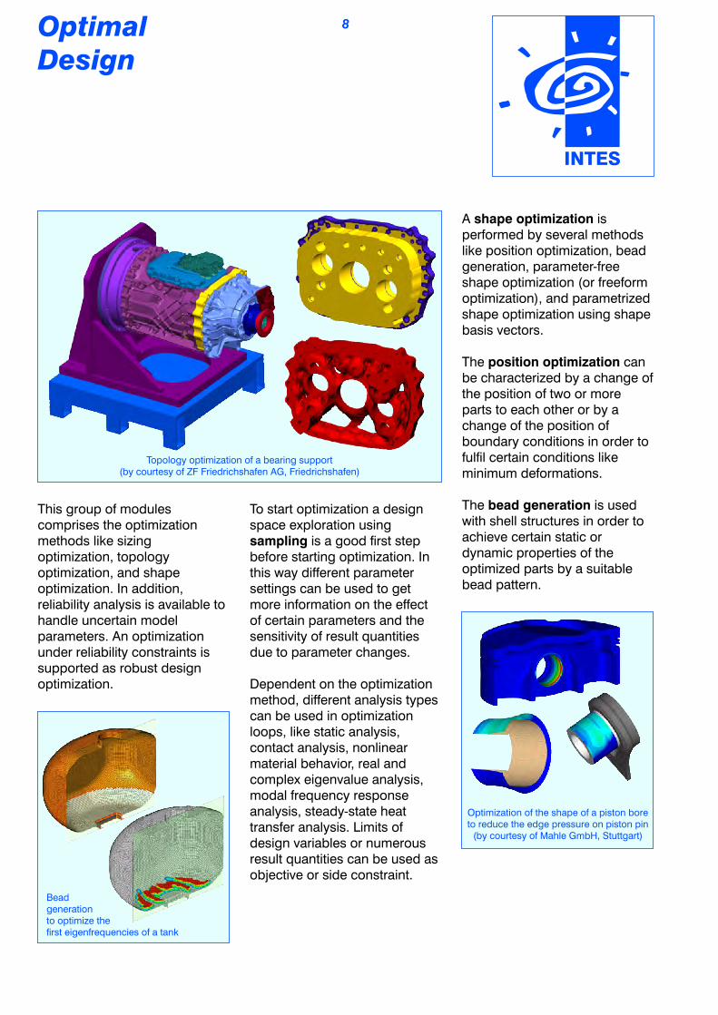
OptimalDesign
Topology optimization of a bearing support(by courtesy of ZF Friedrichshafen AG, Friedrichshafen)
This group of modules comprises the optimization methods like sizing optimization, topology optimization, and shape optimization. In addition, reliability analysis is available to handle uncertain model parameters. An optimization under reliability constraints is supported as robust design optimization.
Bead generation to optimize the rst eigenfrequencies of a tank
A shape optimization is performed by several methods like position optimization, bead generation, parameter-free shape optimization (or freeform optimization), and parametrized shape optimization using shape basis vectors.
The position optimization can be characterized by a change of the position of two or more parts to each other or by a change of the position of boundary conditions in order to full certain conditions like minimum deformations.
The bead generation is used with shell structures in order to achieve certain static or dynamic properties of the optimized parts by a suitable bead pattern.
INTES
Optimization of the shape of a piston bore to reduce the edge pressure on piston pin
(by courtesy of Mahle GmbH, Stuttgart)
To start optimization a design space exploration using sampling is a good rst step before starting optimization. In this way different parameter settings can be used to get more information on the effect of certain parameters and the sensitivity of result quantities due to parameter changes.
Dependent on the optimization method, different analysis types can be used in optimization loops, like static analysis, contact analysis, nonlinear material behavior, real and complex eigenvalue analysis, modal frequency response analysis, steady-state heat transfer analysis. Limits of design variables or numerous result quantities can be used as objective or side constraint.
8

Stress reduction byfreeform optimization of a conrod
The topology optimization starts from a design space in order to nd the optimal material distribution in this design space for a given design objective. Objective and side constraints can be dened in the design space or outside in the other parts of the structure. In addition, manufacturing constraints can be specied for symmetries, release directions, minimum and maximum member sizes to inuence the design. The element lling ratio is used as design variable, which directly inuences stiffness and mass of each element. After convergence, the elements in the design space are either those with lling ratio near one, which represent the desired structural behaviour, or those with lling ratio near zero, which are not needed to achieve this behaviour. After an automatic surface smoothing of the remaining structure, it can be exported as mesh or geometry (STL).
The reliability analysis handles uncertain model parameters and their inuence on the structural behavior. For a given failure mode, it calculates the probability of failure and its sensitivities with regard to the uncertain variables.
A sizing optimization uses other model parameters than node coordinates as design variables like shell thicknesses, beam cross sections, material parameters, property values of spring, mass, and damper elements or even parameters of control elements.
Inuence of sheet thickness deviations on the rst torsional eigenfrequency
OptimalDesign
INTES
The freeform optimization is mainly used to homogenize stress elds or to optimize the weight of parts under stress limits. To achieve that, material can be added or released at complex surfaces in normal direction.
Position optimization of bolts (smallest deformations
and identical bolt force)
9

Other Functions
INTES
This group of modules comprises more analysis modules for electro-magnetics, some special functions like laminate analysis, and an innovative new spot weld concept as well as the interfaces, which are directly supported by PERMAS to other software products.
Electro-thermal analysis of circuit paths in a control unit
Linear static and dynamic electro-magnetic tasks can be solved with the corresponding modules. Generated heat according to the Joule effect or induced forces can be directly used in subsequent structural analysis.
By substructuring, an FE model can be split into an arbitrary number of substructures (so-called components). The components can be assembled like single elements to get a complete structure (so-called conguration).
A conguration can be assembled by an arbitrary number of levels up to the top component (i.e. the root of the substructure tree). Each level may introduce new elements, loads, and boundary conditions.
For the reduction of components, static and dynamic reduction is available. By this way, matrix models can be generated, which represent the FE models of the reduced components and are suitable for model exchange between cooperation partners without exchanging the model details.
10
Dynamic condensation in the engine analysis using substructuring (for the calculation of sound raditaion power) by courtesy of Daimler AG, Stuttgart.
Crankcase
Timing case Oilpan (with oil)Cylinder head
with reduced attached parts
Submodeling for local
renement of meshes
and results
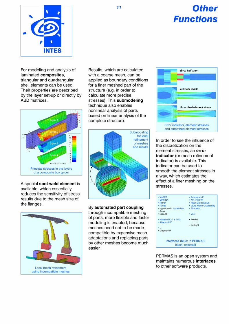
Results, which are calculated with a coarse mesh, can be applied as boundary conditions for a ner meshed part of the structure (e.g. in order to calculate more precise stresses). This submodeling technique also enables nonlinear analysis of parts based on linear analysis of the complete structure.
Local mesh renement using incompatible meshes
By automated part coupling through incompatible meshing of parts, more exible and faster modeling is enabled, because meshes need not to be made compatible by expensive mesh adaptations and replacing parts by other meshes become much easier.
Error indicator, element stresses and smoothed element stresses
In order to see the inuence of the discretization on the element stresses, an error indicator (or mesh renement indicator) is available. This indicator can be used to smooth the element stresses in a way, which estimates the effect of a ner meshing on the stresses.
Other Functions
INTES
For modeling and analysis of laminated composites, triangular and quadrangular shell elements can be used. Their properties are described by the layer set-up or directly by ABD matrices.
Principal stresses in the layers of a composite box girder
A special spot weld element is available, which essentially reduces the sensitivity of stress results due to the mesh size of the anges.
11
• VisPER• MEDINA• Patran• I-deas
Hyperview• Hypermesh, • Ansa• SimLab
• Nastran BDF + OP2• Abaqus INP
• ...• Magmasoft
• Adams MNF• AVL EXCITE• Altair MotionSolve• VLAB Motion, Durability• Simpack
• VAO
• Femfat
• EnSight
Interfaces (blue: in PERMAS, black: external)
PERMAS is an open system and maintains numerous interfaces to other software products.

INTES
VisPERPre/Post
VisPER is the graphical pre- and post-processor of PERMAS. It comprises the pre-processing of PERMAS models (mainly on the basis of already existing meshes) and the post-processing of PERMAS results.
In post-processing, XY plots can be generated using VisPER or 'PERMASgraph', a specialized tool for XY plots.
Beside the specication of element properties, MPC conditions, boundary conditions, and loads, VisPER comprises specialized wizards, which guide the user through the respective modeling steps:
- Contact modeling- Bolt pretension- Topology optimization- Sizing optimization- Shape optimization (with bead generation and position optimization)- Freeform optimization- Fluid-structure coupling- Substructuring- Rigid body mode decoupling (RBM assistant)
Main window of VisPER
300
400
500
600
700
800
900
1000
1100
0 1000 2000 3000 4000 5000 6000
N1123,TN1241,T
N850,TN442,T
N1564,T
Time [s]
Tem
pe
ratu
re[K
]
Temperature distribution over time with 'PERMASgraph'
For the evaluation of spot weld forces, a special method is available, which uses trafc light labeling to visualize critical and non-critical values of the normal and shear forces in spot welds. The stresses can be shown in addition for a full assessment of the stresses in a ange.
Evaluation of spot weld forces
12

Filling ratio >70% Smoothed hull
Topology optimization of a gear wheel with cyclic symmetry
and release directions
Pre- and post-processing for a freeform optimization
VisPER is based on the infrastructure of PERMAS, which provides most of the interfaces in both PERMAS and VisPER in the same way, where VisPER additionally gives the direct visual feedback about the read model to the user.
In addition, results of PERMAS can be exported in other formats.
VisPER has a modern interactive graphical user interface for easy and intuitive application. A simple selection of the shown model parts, working with transparency and cutting planes, the simple generation of animations, and many other useful interactions are supporting the effective and efcient working with this tool.
Comprehensive options for adjustment provide an easy customization to the user's preferred working style. Self-dened abbreviations for standard functions accelerate many operations. Macros using the programming language Python can easily be generated by recording and used later.
VisPER also performs the task of model verication by visualization and evaluation of numerous PERMAS verication results, like projection vectors and unconnected nodes in surface to surface MPC connections. In addition, a message dialog evaluates the PERMAS diagnostic messages and shows the affected model parts directly.
Graphical properties of parts and element sets (S=shown, C=colored, W=wireframe, A=active)
INTES
VisPERPre/Post
13

INTES
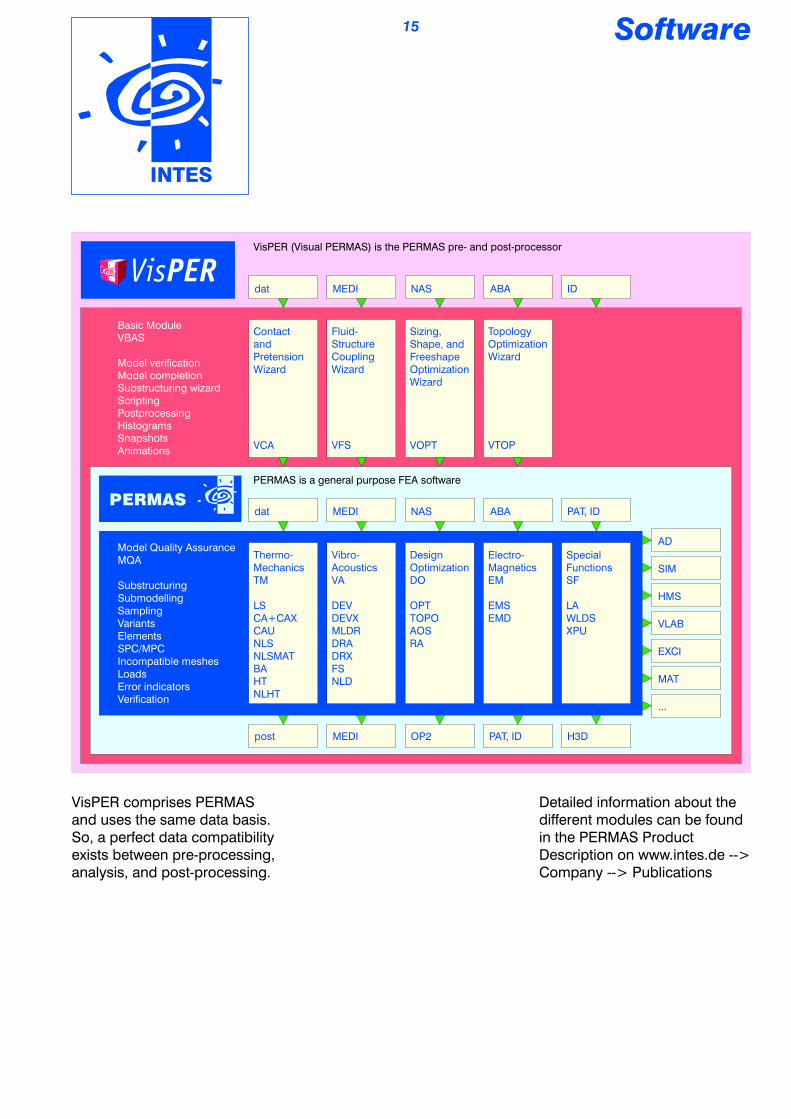
VisPER Modules:
VBAS Basic moduleVCA Contact modelingVOPT Optimization modelsVTOP Topology optimizationVFS Fluid modeling
Model of a transport vehicleby courtesy ofDaimler AG, Stuttgart
Software
PERMAS Modules:
MQA Basic moduleLS Linear static analysisCA+CAX Contact analysisCAU Contact geometry updateNLS Nonlinear static analysisNLSMAT Extended mat. lawsBA Linear buckling analysisHT Heat transferNLHT Nonlinear heat transfer
DEV Dynamics (eigenvalues)DEVX Extended mode analysisMLDR Eigenmodes with MLDRDRA Dynamics (response)DRX Extended dynamicsFS Fluid-structure acousticsNLD Nonlinear dynamics
OPT Design optimizationTOPO Layout optimizationAOS Advanced optim. solversRA Reliability analysis
EMS Electro-/magneto-staticsEMD ElectrodynamicsLA Laminat analysisWLDS Rened weldspot modelXPU GPU accelerator
MEDI MEDINA doorPAT PATRAN doorID I-DEAS doorAD ADAMS interfaceEXCI EXCITE interfaceSIM SimPack interfaceHMS MotionSolve interfaceH3D HYPERVIEW interfaceVLAB Virtual.Lab interfaceMAT MATLAB interfaceNAS NASTRAN doorABA ABAQUS door
14
Detailed information about the different modules can be found in the PERMAS Product Description on www.intes.de --> Company --> Publications
Software
INTES
VisPER comprises PERMAS and uses the same data basis. So, a perfect data compatibility exists between pre-processing, analysis, and post-processing.
15
Model Quality AssuranceMQA
SubstructuringSubmodellingSamplingVariantsElementsSPC/MPCIncompatible meshesLoadsError indicatorsVerification
Thermo-MechanicsTM
LSCA+CAXCAUNLSNLSMATBAHTNLHT
Vibro-AcousticsVA
DEVDEVXMLDRDRADRXFSNLD
Design OptimizationDO
OPTTOPOAOSRA
Electro-MagneticsEM
EMSEMD
Special FunctionsSF
LAWLDSXPU
post MEDI OP2 PAT, ID H3D
AD
SIM
HMS
VLAB
EXCI
MAT
...
Basic ModuleVBAS
Model verificationModel completionSubstructuring wizardScriptingPostprocessingHistogramsSnapshotsAnimations
Contact andPretensionWizard
VCA
Fluid-Structure Coupling Wizard
VFS
Sizing, Shape, andFreeshape Optimization Wizard
VOPT
Topology Optimization Wizard
VTOP
dat MEDI NAS ABA PAT, ID
dat MEDI NAS ABA ID
VisPER (Visual PERMAS) is the PERMAS pre- and post-processor
PERMAS is a general purpose FEA software

If not specied differently, all registered names and trademarks are legally protected brands of INTES or other organizations. The registered trademarks of INTES are PERMAS and VisPER. The use of other product names does not imply that these names are not protected. They are used here only to inform the reader.
INTES GmbHSchulze-Delitzsch-Str. 1670565 Stuttgart, GermanyTel.: +49-711-784990Fax: +49-711-7849910E-mail: [email protected]: www.intes.de
Copyright 2015 INTES GmbH, Stuttgart, all rights reserved.
The nite element model of a tractor transmission on the frontpage appears by courtesy of ZF Friedrichshafen AG in Friedrichshafen, Germany.