performance specification logistics management information · 2016-04-29 · 1 mil-prf-49506 11...
TRANSCRIPT

1
MIL-PRF-49506 11 November 1996
PERFORMANCE SPECIFICATION
LOGISTICS MANAGEMENT INFORMATION
This specification is approved for use by all Departments and Agencies of theDepartment of Defense.
1. SCOPE.
1.1 Scope. This specification describes information required by thegovernment to perform acquisition logistics management functions. Theprinciple focus of this specification is on providing the DOD with acontractual method for acquiring support and support-related engineering andlogistics data from contractors. The DOD uses this data in-house in existingDOD materiel management processes such as those for initial provisioning,cataloging, and item management. Data products intended primarily for in-house use by the contractor during his/her own design process or thosedeveloped internally by the DOD are beyond the scope of this document. Depending on specific program requirements, this information may be in theform of summary reports, a set of specific data products, or both. Thisspecification identifies content requirements for information summaries and format requirement for data products. It may be used on all system/end itemacquisition programs. The contractor may, and is encouraged to, suggestalternative means of satisfying requirements of this specification to makeinformation more readily available and to utilize more efficient businesspractices. The mechanics of delivery (e.g., electronic data interchange, hardcopy, etc.) are not within the scope of this specification and should beaddressed separately. Data entry media, storage, and maintenance proceduresare left to the contractor.
AMSC A7217 FSC ALSS
DISTRIBUTION STATEMENT A. Approved for public release; distribution isunlimited.

MIL-PRF-49506
2
2. APPLICABLE DOCUMENTS.
2.1 General. The documents listed in this section are specified insections 3, 4, and the referenced appendices from these sections of thisspecification. This section does not include documents cited in othersections of this specification or recommended for additional information or asexamples. While every effort has been made to ensure the completeness of thislist, document users are cautioned that they must meet all specifiedrequirements documents cited in sections 3 and 4 of this specification,whether or not they are listed.
2.2 Government documents.
2.2.1 Specifications, standards, and handbooks. The followingspecifications, standards, and handbooks form a part of this document to theextent specified herein. Unless otherwise specified, the issues of thesedocuments are those listed in the issue of the Department of Defense Index ofSpecifications and Standards (DODISS), and supplement thereto, cited in thesolicitation.
Department of Defense Specifications
MIL-T-31000 Technical Data Packages, General Specifications for
MIL-C-7024 Calibrating Fluid, Aircraft Fuel System Components
Federal Standards
H4/H8 Commercial and Government Entity Code
H6-1 Federal Item Name Directory for Supply Cataloging
Department of Defense Standards.
MIL-STD-196 Joint Electronics Type Designation System
MIL-STD-965 Parts Control Program
MIL-STD-1812 Type Designation, Assignment and Method for Obtaining
MIL-STD-2073 DOD Materiel, Procedures for Development and Application of Packaging Requirements
(Unless otherwise indicated, copies of federal and military specifications,standards, and handbooks are available from the Standardization DocumentsOrder Desk, Building 4D, 700 Robbins Avenue, Philadelphia, PA 19111-5094.)
2.2.2 Other Government documents, drawings, and publications. Thefollowing other government documents, drawings, and publications form a partof this document to the extent specified herein. Unless otherwise specified,the issues are those cited in the solicitation.
Other Documents.
AR 700-82 Joint Regulation Governing the Use and Application ofOPNAVINST 4410.2 Uniform Source Maintenance and Recoverability CodesAFR 66-45MCO 4400.120DSAR 4100.6
DOD 4l00.39-M Federal Logistics Information SystemNAVSUP PUB 437 MILSTRIP/MILSTRAP (Military Standard Requisitioning and Issue Procedures/Military Standard Transaction Reporting

MIL-PRF-49506
3
and Accounting Procedures
NAVSUP PUB 485 Afloat Supply Procedures
(Copies of specifications, standards, drawings, and other government documentsrequired by contractors in connection with specific acquisition functionsshould be obtained from the contracting activity or as directed by thecontracting activity.)
2.3 Non-Government Publications. The following document(s) form a partof this document to the extent specified herein. Unless otherwise specified,the issues of the documents which are DOD adopted are those listed in theissue of the DODISS cited in the solicitation. Unless otherwise specified,the issues of documents not listed in the DODISS are the issues of thedocuments cited in the solicitation (see 6.2).
IEEE 200-75 Electrical and Electronics Parts and Equipment; Reference Designations for
(Non-government standards and other publications are normally available fromthe organizations that prepare or distribute the documents. The IEEE 200-75is available from the Institute of Electrical and Electronics Engineers, 445Hoes Lane, P.O. Box 1331, Piscataway, NJ 08855-1331. These documents alsomay be available in or through libraries or other informational services.)
2.4 Order of Precedence. In the event of a conflict between the text ofthis document and the references cited herein, the text of this document takesprecedence. Nothing in this document, however, supersedes applicable laws andregulations unless a specific exemption has been obtained.
3. REQUIREMENTS.
3.1 General. Logistics Management Information (LMI) is acquired toprovide item sustainment data on a materiel system and information needed forplanning, assessing program status, and program decisions. Beforerequirements of this specification are imposed, other commercial equivalentproducts or processes which satisfy government information needs will beconsidered. Contractor shall ensure that information provided under thisspecification is coordinated with the data requirements of other programelements to eliminate inconsistencies between deliverables.
3.2 Product Requirements.
3.2.1 Supportability Analysis Summaries. The Supportability AnalysisSummaries (SAS) provide information for planning, assessing program status,and decision making by the government relative to various logisticsdisciplines. Appendix A describes the general requirements for each summary.The SAS shall contain information identified on the worksheets (figure 1).
3.2.1.1 SAS Level of Detail. The contractor shall provide SAS in theformat and to the level of detail specified on contract.
3.2.1.2 SAS Current Design Configuration. The contractor shall provideSAS information which reflects current design configuration.
3.2.2 LMI Data Products. The data definitions, edits, and data formatsdescribed in appendix B shall be adhered to by the contractor in deliveringthe data. The worksheet (figure 2) shall be used to identify the requireddata products.
3.2.2.1 Data Product Level of Detail. Contractor shall provide data tothe level of detail specified in the contract.

MIL-PRF-49506
4
3.2.2.2 Data Product Current Design Configuration. Contractor shallprovide data which reflects the current design configuration.
4. VERIFICATION.
4.1 General. The SAS and LMI Data Products will be verified by thegovernment.
4.2 Supportability Analysis Summaries.
4.2.1 SAS Level of Detail. Contractor=s summaries will be verified bythe government to ensure they reflect the required level of detail asspecified in the contract. Verification criteria for level of detail shall bespecified in the contract.
4.2.2 SAS Accuracy Verification. Contractor=s summaries will be verifiedby the government to ensure they accurately reflect the current designconfiguration. Verification criteria for summaries accuracy shall bespecified in the contract.
4.3 LMI Data Products.
4.3.1 Data Product Level of Detail. Contractor=s data will be verifiedby the government to ensure that it is documented to the level of detailspecified in the contract. Verification criteria for level of detail shall bespecified in the contract.
4.3.2 Data Product Accuracy Verification. Contractor=s data will beverified by the government to ensure that it accurately reflects the currentdesign configuration. Verification criteria for data accuracy shall bespecified in the contract.
5. PACKAGING.
5.1 General. Packaging of the LMI Data Products is not applicable to thisspecification.
6. NOTES.
(This section contains information of a general or explanatory nature thatmay be helpful, but is not mandatory.)
6.1 Intended Use. This specification contains requirements which areapplicable to the acquisition of military systems and equipment. Theacquisition logistics management information should be in sufficient detail toallow for program decision making, assessing program status, planning, andultimately item sustainment. The detail required of this information shouldbe based on program specifics such as, but not limited to, life cycle phase,type of program, hardware complexity, operations and support concept, anddegree of program control.
6.2 Issue of DODISS. When this specification is used in acquisition, theapplicable issue of the DODISS must be cited in the solicitation.
6.3 Consideration of Data Requirements. This specification is cited inDOD 5010.12-L, Acquisition Management Systems and Data Requirements ControlList (AMSDL), as the source document for the following Data Item Description(DID). When it is necessary to obtain the data, the applicable DID must belisted on the Contract Data Requirements List (DD Form 1423), except where theDOD Federal Acquisition Regulations Supplement exempts the requirement for aDD Form 1423.

MIL-PRF-49506
5
DID Number DID Title
DI-ALSS-81529 Logistics Management Information (LMI) Data Product(s) DI-ALSS-81530 Logistics Management Information (LMI) Summaries
The above DIDs were current as of the date of this specification. The currentissue of the AMSDL must be researched to ensure that only current and approvedDIDs are cited on DD Form 1423.
6.4. Acronyms. The acronyms used in this specification are defined inappendix C.
6.5 Definitions. The data definitions for the interface part of thisspecification are defined in the data dictionary appendix C of thisspecification. In addition, for the purposes of this specification, thefollowing definitions shall apply:
6.5.1 Assembly. A number of parts or subassemblies, or any combinationthereof, joined together to perform a specific function and capable ofdisassembly (e.g., power shovel-front, fan assembly, audio frequencyamplifier). NOTE: The distinction between an assembly and subassembly isdetermined by the individual application. An assembly, in one instance, maybe a subassembly in another where it forms a portion of an assembly.
6.5.2 Attaching part. An item used to attach assemblies or parts to theequipment or to each other.
6.5.3 Component. An assembly or any combination of parts, subassemblies,and assemblies mounted together normally capable of independent operation in avariety of situations.
6.5.4 Contractor. Contractor may consist of industry or a governmentactivity under the terms of a contract.
6.5.5 Design Change. An approved engineering change incorporated intothe end item which modifies, adds to, deletes, or supersedes parts in the enditem.
6.5.6 End Item. A final combination of end products, componentparts/materials which is ready for its intended use, e.g., ship, tank, mobilemachine shop, aircraft, receiver, rifle, or recorder.
6.5.7 Hardware Breakdown. A breakdown accomplished by sequencing allparts comprising the end item in a lateral and descending "familytree/generation breakdown." This breakdown shall consist of the end item,including all components, listing every assembly, subassembly, and parts whichcan be disassembled, reassembled/replaced. All parts are listed in theirrelation to the end item, component, assembly, or installation system in whichthey are contained and to their own further sub-subassemblies and parts. Thisrelationship is shown by means of an indenture code.
6.5.8 Part. One piece, or more than one piece joined together, which arenot normally subject to disassembly without destruction or impairment ofdesigned use.
6.5.9 Repair Part. Material capable of separate supply and replacementwhich is required for the maintenance, overhaul, or repair of a system,equipment, or end item. This definition does not include support equipment,but does include repair parts for support equipment.
6.5.10 Spares. Articles identical to or interchangeable with repairableitems which are procured for support of a system, over and above the quantityneeded for initial assembly of the system.
MIL-PRF-49506
6
6.5.11 Subassembly. Two or more parts which form a portion of anassembly or a component replaceable as a whole, but having a part or partswhich are individually replaceable (e.g., gun mount stand, window recoilmechanism, floating piston, telephone dial, mounting board with mounted parts,power shovel dipper stick).
6.5.12 Support Equipment. "Support Equipment" is that equipment requiredto make an item, system, or facility operational in its intended environment.This includes all equipment required to maintain and operate the item, system,or facility including aerospace ground equipment and ground equipment.
6.5.13 Support Items. Items subordinate to or associated with an enditem, i.e., spares, repair parts, and support equipment.
6.6 Subject Term (Key Word) Listing. Subject keywords allowidentification of this document during retrieval searches.
LMIProvisioningSupport EquipmentItem ManagementSupportabilitySupportability Analysis SummariesMaintenance PlanningRepair AnalysisSupport and Test EquipmentSupply SupportManpower, Personnel, and TrainingFacilitiesPackaging, Handling, Storage, and TransportationPost Production Support
6.7 Guidance.
6.7.1 Data Organization. The DOD has a number of standard data systemsfor wholesale materiel management which require data in a specific format. The contractor may interface directly with the customer data systems. Anindentured structure, with requiring authority approval, should be utilizedfor summaries and data products where required. The structure should depictrelationships between assemblies, components, and other assemblies.
6.7.2 LMI Development. The contractor should suggest to the governmentthe most effective method of LMI development, delivery, and eliminatingunnecessary intermediate steps or deliverables.
6.8 Electronic Delivery of LMI. Electronic data interchange, onlineaccess, and all other automation issues are outside the scope of theMIL-PRF-49506, LMI and must be addressed separately using other appropriatedocuments such as MIL-STD-1840, Automated Interchange of TechnicalInformation.

MIL-PRF-49506
7
CONCLUDING MATERIAL
Custodians: Preparing Activity: Army - TM Army - TM (Project No. ALSS-0003)
Review Activities: Navy - AS, MC Air Force - 10 Miscellaneous DOD/NASA - NS, DC

MIL-PRF-49506APPENDIX A
8
SUPPORTABILITY ANALYSIS SUMMARIES
A.1 SCOPE.
A.1.1 Scope. The following reports shall consist of information requiredfor the requiring authority to conduct logistics planning and analysis,influence program decisions, assess design status, and verify contractorperformance. Several information summaries are presented as examples of otheruseful support information that DOD managers may want to request from acontractor. These are not all inclusive or exclusive and are intentionallydescribed in general terms to encourage maximum contractor flexibility. Thecontent of the summaries is not limited to information and data products citedin the LMI specification. Content of the summaries should be specified onSupportability Analysis Summaries Worksheet (figure 1). Data not included inappendix B shall be defined on the worksheet (figure 1). The individualrequirements should be taken into consideration when requesting these types ofsummaries. They can be delivered as stand alone reports or as an integralpart of other systems engineering documentation. Requirements for thesesummaries shall be coordinated with data requirements of other programfunctional elements to minimize redundancies and inconsistencies. Thefollowing paragraphs describe report content in general terms. Specificcontent of each summary will be specified in the contract. Government andcontractor should hold open dialogues to establish a format which both canuse. Contractor format is acceptable when approved by the government. Thisappendix is a mandatory part of this specification.
A.2 Maintenance Planning. These summaries provide maintenance planninginformation to the government that may be used to develop initial fieldingplans for the end items support structure. These summaries may also be usedto verify that the maintenance actions and support structure are aligned withthe government=s requirements and maintenance concept. The informationcontained within these summaries are associated with repairable items to thelevel of detail specified on contract. The repairable items should beidentified within the hierarchy of the end item broken down by an agreed uponconfiguration control method. It should identify all preventive andcorrective maintenance actions along with the required spares and supportequipment. These summaries should also provide supporting informationjustifying the need for each maintenance action, e.g., elapsed time ofmaintenance actions; task frequency; failure rate of an item; Mean Time ToRepair an item; and an item=s man-hour allocation by maintenance action andlevel.
A.3 Repair Analysis. These summaries provide the government withconclusions and recommendations of the maintenance repair analysis. Thegovernment may verify the conclusions and recommendations by utilizingcontractor=s inputs to perform an in-house analysis. These summaries may alsobe used by the government to develop initial fielding plans for the end item =ssupport structure. The conclusions may include actions and recommendationsfor influencing the system design; a listing of which items should be repairedand which should be discarded. These summaries may identify for each itembeing repaired the level of maintenance at which the repair should beperformed and associated costs. These summaries may identify for the systemsupport structure, the operational readiness achieved, and the placement andallocation of spares, support equipment, and personnel.
These summaries may also include other information for the analysis performed,e.g., a listing of the input data and their corresponding values and sourcesof the data; operational scenario modeled; assumptions made; constraints andnoneconomic factors imposed on the system; maintenance alternativesconsidered; the analytical method and model used to perform the economicevaluations; and discussion of the sensitivity evaluations performed andresults obtained.
MIL-PRF-49506APPENDIX A
9
A.4 Support and Test Equipment. These summaries provide data necessaryto register, or verify the registry of, the support or test equipment in thegovernment=s inventory. They may provide details of the Test Measurement andDiagnostic Equipment (TMDE) calibration procedures, technical parameters, andany piece of support equipment needed to support the required supportequipment.
A.5 Supply Support. These summaries provide the government withinformation on static and application related hardware information which maybe used to determine initial requirements and cataloging of support items tobe procured through the provisioning process. These summaries may include theidentification of the system breakdown, maintenance coding, maintenancereplacement factors, overhaul rates, roll-up quantities, design changeinformation, and associated technical manuals, as applicable. These summariesmay show information on different categories of provisional items such as longlead items, bulk items, tools and test equipment, etc. They may also allowfor review of Provisioning List Item Sequence Number (PLISN) assignment orcross referencing PLISNs with reference numbers.
A.6 Manpower, Personnel, and Training. These summaries provideinformation to the government so it can establish training plans and ensuremanpower and personnel constraints are met. The information contained withinthis report should identify items = corrective and preventive maintenancetasks, operations tasks, manpower estimates for each task by maintenancelevel, personnel skills required to perform the maintenance tasks, and anytraining required to allow these tasks to be performed. The informationcontained within this area is associated with items to the level of detailspecified on contract. The items should be identified within the hierarchy ofthe end item broken down by an agreed upon configuration control method.
A.7 Facilities. These summaries identify the facilities required tomaintain, operate, train, and test an item. The facilities may beorganizational, intermediate, or depot maintenance, training, mobile and testfacilities. The summary information contained within shall help plan for anymodification to an existing facility or development of a new facility. Theinformation shall be associated with repairable items to the level of detailspecified in the contract. The repairable items should be identified withinthe hierarchy of the end item broken down by an agreed upon configurationcontrol method. Data provided must be in compliance with all DOD and nationalhealth, life, and environmental codes. National standards and terminologyused by the construction industry for civil, electrical, mechanical, etc.,specialties should be used.
A.8 Packaging, Handling, Storage, and Transportation. These summariesidentify packaging, handling, and storage requirements. They also provideinformation relevant to the development of a transportability analysis report.The information contained within this area is associated with the referencenumber and Commercial And Government Entity (CAGE) to the level of detailspecified on contract. The information contained within this area isassociated with repairable items to the level of detail specified on contract.The repairable items should be identified within the hierarchy of the end itembroken down by an agreed upon configuration control method.
A.9 Post Production Support. The purpose of these summaries is toanalyze life cycle support requirements of the new system/equipment/softwareprior to closing of production lines to ensure the system/equipment/ software=s remaining life. These summaries identify support items associatedwith the system/equipment/software that will present potential problems due toinadequate sources of supply, support capability, or modification aftershutdown of production lines. They also identify alternative solutions foranticipated support difficulties during the remaining life of the system/

MIL-PRF-49506APPENDIX A
10
equipment/software. General topics that may also be addressed in thesesummaries are manufacturing, repair centers, data modifications, supplymanagement, configuration management, and other related areas.

MIL-PRF-49506 APPENDIX A Page ____ of ____
FIGURE 1 - WORKSHEET 1 - SUPPORTABILITY ANALYSIS SUMMARIES
11
SUMMARY TITLE:
SPECIFIC INSTRUCTIONS:
DATA IN LMI SPECIFICATION (Please provide the data product title):________________________ __________________________ _____________________________________________ __________________________ _____________________________________________ __________________________ _____________________________________________ __________________________ _____________________________________________ __________________________ _____________________________________________ __________________________ _____________________________________________ __________________________ _____________________________________________ __________________________ _____________________
DATA NOT IN LMI SPECIFICATION (Please provide the data product title, its definitionand its format):
SUMMARY LAYOUT (if applicable): Government Provided G Contractor Provided G

MIL-PRF-49506APPENDIX B
12
LMI DATA PRODUCTS DICTIONARY
B.1 SCOPE.
B.1.1 Scope. This appendix provides the definitions for the LMI dataproducts and their associated names. This appendix is a mandatory part ofthis specification.
B.2 Sections. The LMI Data Product Dictionary contains some or all ofthe following entries. When a standard data acronym applies, this is alsolisted in this section.
a. Data Product Dictionary Number (DPD #)
b. Data title with acronym
c. Field format
d. Definition
e. Data item(s)
f. Data code(s)
g. Associated name(s)
B.2.1 Format. The general format for the DPD is as follows:
DPD# DATA TITLE FIELD FORMAT (ACRONYM)
DATA DEFINITION
DATA ITEM(S) DATA CODE(S)
ASSOCIATED NAME(S)
Example of actual entry:
0050 BASIS OF ISSUE (BOI) 15 X - -
This field is composed of the following four subfields:
a. Quantity Authorized (QTY-AUTH) 5 N R -
The quantity of an item (special tool) authorized for the end item density spread or for the unit level specified.
b. End Item 8 X L -
The density spread of the end items.
c. Level l A F -
A code which indicates the unit level authorized for the QTY-AUTH.
QTY-AUTH per lettered company A QTY-AUTH per battalion (BN) headquarters (HQ) B when BN has a service (SVC) company QTY-AUTH per HQ of units above BN level C QTY-AUTH by BN and brigade (BDG) type HQ D (except when BN or BDG has SVC company)

MIL-PRF-49506APPENDIX B
13
QTY-AUTH by SVC battery/company E QTY-AUTH by numbered battery/company and similar F HQ performing ORG maintenance for other units
d. Control l N F -
A code l-9 used for sequencing and controlling BOI entries.
B.2.2 Definition of terms.
B.2.2.1 DPD#. A sequentially assigned number to each data product in thedictionary for use in locating and referencing it throughout the dictionary.
B.2.2.2 Data title. The noun phrase name used to identify the data. Sufficient adjectival modifiers are used with the noun name to ensure titleuniqueness.
B.2.2.3 Field format. A specification for the length, type, positionaljustification, and decimal placement of a data field, or subfield thereof, asdescribed below:
a. Length. The number of character positions in the data. In the eventthe length is variable, the maximum length is specified.
b. Type. A specification of the character type, wherein:
"A" specifies that all characters of the data entry are upper case alphabetical.
"N" specifies that all characters of the data entry are numerical.
"X" specifies that characters of the data entry are upper case alphabetical, numerical, special, or any combination thereof.
"D" specifies that characters of the data entry are numerical with floating decimal. Decimals may be entered as required or exponentially, e.g., "0.0000325" or "3.25E-5".
c. Justification. Specifies from which side of the field the charactersof the data are entered. Those starting at the left are left justified (L),those starting at the right are right justified (R). Those which alwaysoccupy the entire field are fixed (F).
d. Decimal Placement. Specifies the number of character positions to theright of the assumed decimal point when the data is numeric in allcharacter positions. “AS” means "As Specified" and the detailed instructionswill indicate the location of decimal points.
e. A dash (-) used in any column signifies that it is not applicable.
B.2.2.4 Data Definition. A narrative definition of the data insufficient detail to present a clear and complete understanding of the precisedata or element of information that the data represents.
B.2.2.5 Data item. One of a set of descriptive items of information orvalues that apply to a data product.
B.2.2.6 Data code. One or more alphabetical, numerical, specialcharacters, or any combination thereof, that represent a data item. A code isused instead of the data item itself, in order to conserve space.
Note 1: In some cases, a position left blank counts as a data code signifying

MIL-PRF-49506APPENDIX B
14
some particular data item value as specified in the dictionary.
Note 2: When data items and data codes are too voluminous to be included inthis document, reference is made to items and codes in another document.
B.2.2.7 Associated name. A unique modifier of a data title whichdescribes the use/application of the data.

MIL-PRF-49506APPENDIX B
15
LMI DATA PRODUCT DICTIONARY
0010 ALLOWANCE ITEM CODE (AIC) 2 X F -
Consists of two subfields: Allowance Type and Allowance Code.
a. Allowance Type l A F -
A code which indicates the type of item.
Basic issue item category code (Army) A Allowance note code (Navy) B Technical override (TOR) code (Navy) C Allowance factor code (Air Force) D Stockage list category (Marine Corps) E
b. Allowance Code l X F -
A code which further defines and categorizes the allowance type.
(l) When an Allowance Type code of "A" is specified, one of the following codes must be used for Allowance Code:
Basic issue item A Component of end item C Expendable/durable supplies and materials D Additional authorization list items (modified E table of organization and equipment) Additional authorization list items (other) F
(2) When an Allowance Type code of "B" is specified, one of the following codes must be used for Allowance Code:
Indicates an operating space item regardless of vessel type. 1 The Stock Number Sequence List (SNSL) reflects a quantity for each application.
REFER TO YOUR ALLOWANCE PARTS LIST (APL) to determine if the 2 repair part is required (since exceptions are annotated on the APL when the repair part may not be required) or where a choice must be made to select the correct repair part.
Represents the superseding repair part due to redesign or 3 material change. The superseded stock number appears as alternate information in part III, section D, of the Coordinated Shipboard/Allowance List (COSAL). The superseded item, presently on board, can be used without adverse effect to the component. If the superseded item is presently on board, utilize the stock under the superseded number before ordering deficiencies.
An item with an NSN for bulk material that is to be used 4 in the fabrication of the item listed in the parts list. Requisition as required.
Denotes CLASSIFIED PART and should be requisitioned 5 and stored IAW current security regulations.
An RSS (Ready Service Spare) which will appear in the 6 COSAL section III CR of the SNSL. This item may also appear in section IIIA of the SNSL as a storeroom item for this APL application if anticipated usage warrants

MIL-PRF-49506APPENDIX B
16
backup support.
Denotes an item that is to be requisitioned and stowed 7 IAW confidential instructions. This note applies to operating frequency control crystals allowance.
Indicates an accessory component/components applicable to 8 a parent equipment.
Item(s)/part(s) for which only the Commanding Officer 9 or his designated representative is specifically responsible for the physical custody and safekeeping thereof.
Represents an item that has been coded to deviate from A the NORMAL MAINTENANCE POLICY expressed by the Lead APL. The responsible hardware command authorizing this deviation will be annotated in the characteristic portion of the APLs.
Indicates that the ORDNANCE alteration has been performed C and repair parts are not required.
Applicable to S/O/S (SHIPALT/ORDALT/SPALT) items, indicates D the quantity by which the affected APL population of the item has been decreased after accomplishment of the S/O/S.
Indicates that a Technical Override (TOR) or Planned Maint- E enance Requirement (PMR) is included in the allowed quantity.
Indicates that note codes 3 and E, above, apply to the item. F
Indicates that note codes 2 and E, above, apply to the item. G
Represents an item listed on Allowance Equipage Lists H (AEL) to provide technical information only and is not an authorized allowance.
Indicates that note code l or X and note code 2 both J apply to the item.
Represents a module required to execute approved mainte- N nance planning which calls for identifying the fault or failed module through progressive/selective module substitution. Maintenance Assistance Modules (MAM) will be included as an Operating Space Item (OSI) in the COSAL, section III CF of the Stock Number Sequence List (SNSL). The item may also appear in section IIIA of the SNSL as a storeroom item for this APL application if anticipated usage warrants backup support.
Represents the preferred item in a situation where two or S more items are interchangeable. The alternate nonpreferred item(s), if presently on board, may be utilized to satisfy the allowance requirement; however, when a shortage exists, the preferred item of stock should be requisitioned. The alternate item of stock will appear in the Preferred-to- Alternate Substitute Cross-Reference List.
Select at test. All NSNs required for the selection are T listed for each circuit symbol. Item needed must be selected from among the listed NSNs based on equipment operating requirements. A suffix has been assigned to the circuit symbol for identification.
MIL-PRF-49506APPENDIX B
17
Variable. See the characteristics portion of APL. V
APL will state: NSN...has been canceled -- it cannot W be procured. When part fails, replace with the next higher assembly.
Indicates an operating space item. The SNSL quantity is X established by the highest single application quantity in all of the items X code applications.
On Board Repair Part (OBRP) Kits. OBRP quantities are Z included in the APPL (Application) column of section B and the QTY in one equip/comp columns of section A. These kits should be retained as OBRP even if not listed in the COSAL SNSL/Integrated Stock List (ISL).
(3) When an Allowance Type code of "C" is specified, one of the following codes must be used for Allowance Code.
Operational Availability Override Requirement. A Indicates that the Allowance Override quantity (COO7A) finite quantities determine the allowance quantity for the Operational Availability computational math model. For a given item, a comparison between the single highest "A" quantity, other overrides, the sum of all PMR, and the computed demand-based quantity, is made and the highest single quantity is selected as the authorized allowance.
Critical Candidate. Identifies items to be stored C as higher supply echelons (see Note l below).
Disapproved Technical Override. TOR reviewed and D disapproved by the cognizant Hardware Systems Command for .25 Fleet Logistic Support Improvement Program (FLSIP) computations, under .l5 computation item allowance determined by the C007A finite quantities (see Note 2 below).
Early Supply Support (ESS). Indicates that the E finite quantity in C007A is used in place of the quantity per allocation for allowance computation.
Approved TOR Mission Override. TOR accepted to M support primary mission. The C007A finite quantity determines the allowance for a particular item.
Planned Maintenance Requirement (PMR). Indicates P that the C007A finite quantities for an item are additive across all applications, and the summarized PMR quantity determines the authorized allowance when compared with other overrides and the computed demand-based allowance.
Requisition as Required. Indicates that "AR" R is printed in the quantity field for an item. Programs disregard quantities in C007A. "R" overrides all other populations for an item.
Safety Equipment. Specified C007A quantity is S justified allowance to ensure safety and preserve life.

MIL-PRF-49506APPENDIX B
18
Technical Override. Indicates that the highest T finite C007A quantity for a given item is compared with the summarized PMR quantity, other override quantities, and the demand-based computed quantity, the highest of these quantities becomes the authorized allowance. Applies to .l5 FLSIP only.
Disapproved TOR. Justification reserved for future V use.
Operational Availability Underride. Indicates that Y the item population for this application is not used to determine allowance quantities. No finite quantity is loaded in C007A (used to exclude items from the Operational Availability model).
Zero Override. Indicates that the item population Z for this application is not used to determine allowance quantities. No finite quantity is loaded in C007A. Used to exclude items from FLSIP model.
NOTE:
l. An informational code designed to assist in the future selection of items to be stocked at higher echelons. Instructions for the use of this code will be provided by the requiring authority. C-coded items will be processed in the same manner as D-coded items.
2. D-coded items will still be considered as valid candidates for on- board stocking and can be included on allowances if other support criteria is met.
(4) When an Allowance Type code of "D" is specified, the requiring authority will specify the code to be used for Allowance Code.
(5) When an Allowance Type code of "E" is specified, one of the following codes must be used for Allowance Code:
Principal end item A Using unit responsible item C Supply system responsible item D Collateral Equipment E
0020 ALLOWANCE ITEM QUANTITY 3 N R -
A quantity which is defined by the Allowance Item Code (0010).
0030 ALTERNATE INDENTURED PRODUCT CODE (AIPC) 3 N F -
A code used to allow documentation of multiple models of a system/ equipment, or alternate design considerations of an item, using the same Indentured Product Code (IPC) breakdown.
Note: AIPC of zero zero zero "000" will always be used as the basic system. There are no blanks allowed. AIPC =s will be assigned from 001 to 999 in ascending order.
ALTERNATE IPC - UUT. An AIPC of the Unit Under Test (UUT).
0040 AUTOMATIC DATA PROCESSING l N F - EQUIPMENT CODE

MIL-PRF-49506APPENDIX B
19
A code which identifies an item of Automatic Data Processing Equipment (ADPE) or containing ADPE, regardless of Federal Supply Classification (FSC) to provide visibility for compliance with unique manager requirement established for ADPE by Public Law 89-306. Applicable codes are contained in DOD 4l00.39-M.
0050 BASIS OF ISSUE (BOI) 15 X - -
This field is composed of the following four subfields:
a. Quantity Authorized (QTY-AUTH) 5 N R -
The quantity of an item (special tool) authorized for the end item density spread or for the unit level specified.
b. End Item 8 X L -
The density spread of the end items.
c. Level l A F -
A code which indicates the unit level authorized for the QTY-AUTH.
QTY-AUTH per lettered company A QTY-AUTH per battalion (BN) headquarters (HQ) B when BN has a service (SVC) company QTY-AUTH per HQ of units above BN level C QTY-AUTH by BN and brigade (BDG) type HQ D (except when BN or BDG has SVC company) QTY-AUTH by SVC battery/company E QTY-AUTH by numbered battery/company and similar F HQ performing ORG maintenance for other units
d. Control l N F -
A code l-9 used for sequencing and controlling BOI entries.
0060 CALIBRATION AND MEASUREMENT REQUIREMENTS 1 A F - SUMMARY RECOMMENDED
A field depicting whether or not a Calibration and Measurement Requirements Summary is recommended. Codes are as follows:
Calibration and Measurement Requirements Y Summary (CMRS) recommended Not recommended for CMRS N
0070 CALIBRATION INTERVAL 2 N R -
The frequency in months between which a support/test equipment must be calibrated in order to operate within specified tolerances.
0080 CALIBRATION ITEM l A F -
A single position code indicating that the item recommended is itself an item of calibration equipment.
Item is a calibration item Y Item is not a calibration item N
0090 CALIBRATION PROCEDURE 20 X L -

MIL-PRF-49506APPENDIX B
20
The technical manual/order number or instructions that specifies the calibration procedure. For items of TMDE that have an approved method of support, list the applicable military department approved calibration procedure, technical order, or maintenance technical order in the item name block.
0100 CALIBRATION REQUIRED 1 A F -
A single position code indicating whether the support/test equipment recommended or procured requires calibration.
Calibration required Y Calibration not required N
0110 CALIBRATION TIME 5 N R 1
The time, in hours, required to calibrate the support/test equipment.
0120 CHANGE AUTHORITY NUMBER l5 X L -
A number to uniquely identify an authority for an engineering change. The change authority and a numbering sequence will be provided by the requiring authority.
0130 CLEANING AND DRYING PROCEDURE 1 X F -
A code which identifies the procedure for removing soil from parts and the procedure to accomplish the subsequent drying of the cleaned part. For applicable codes, see MIL-STD-2073.
0140 COMMERCIAL AND GOVERNMENT ENTITY (CAGE) CODE 5 X F -
A five-character code assigned by the Defense Logistics Services Center (DLSC) to the design control activity or actual manufacturer of an item as contained in the Cataloging Handbook H4/H8 Series.
CAGE CODE - ADAPTER INTERCONNECTOR DEVICE. A CAGE of the adapter interconnector device used in conjunction with the support equipment (SE).
CAGE CODE - ARN. A CAGE of the additional reference number.
CAGE CODE - ARN ITEM. A CAGE of the primary item reference number.
CAGE CODE - ARTICLES REQUIRING SUPPORT. A CAGE of the article requiring support.
CAGE CODE - ATE. A CAGE of the automated test equipment.
CAGE CODE - CATEGORY III SE. A CAGE of the SE which measures the SE Unit Under Test (UUT).
CAGE CODE - CTIC. A CAGE associated with the CTIC.
CAGE CODE - PACKAGING DATA PREPARER. A CAGE of the packaging data preparer.
CAGE CODE - SUPPORT EQUIPMENT. A CAGE of the SE under analysis. CAGE CODE - TEST PROGRAM SETS. A CAGE of the test program sets used in conjunction with the SE.

MIL-PRF-49506APPENDIX B
21
CAGE CODE - UUT. A CAGE of the UUT.
0150 CONTRACTOR FURNISHED EQUIPMENT/ 1 A F - GOVERNMENT FURNISHED EQUIPMENT (CFE/GFE)
A single-position code indicating the contractor’s recommendation for supply action.
Contractor Furnished C Government Furnished G
0160 CONTRACTOR RECOMMENDED 1 A F -
A code to signify whether or not the corresponding requirements are contractor recommended. Codes are as follows:
YES "Y" NO "N"
CONTRACTOR RECOMMENDED - DDCC. Identify the requirements for the design data category code and if there contractor recommended.
CONTRACTOR RECOMMENDED - IRCC. Identify the requirements for the integrated logistics support requirement category code and if they are contractor recommended.
0170 CONTRACTOR TECHNICAL INFORMATION CODE 2 A - - (CTIC)
A code which indicates specific information regarding the technical process/data required to procure or produce the support item.
a. The first position of the CTIC contains a Breakout Recommenda - tion Code. For a Navy acquisition program, the only applicable code is "C", which does not relate to first position code "C" of this DD.
Recommended for Breakout A Not Recommended for Breakout - Safety B Not Recommended for Breakout - Warranty C Not Recommended for Breakout - Unstable Design D Not Recommended for Breakout - Value Added E Not Recommended for Breakout - Other/Combination F
Note: If code "F" is used, remarks block of provisioning list will contain elaboration.
b. Codes for the second position are as follows:
Source(s) are specified on "Source Control", B "Altered Item", or "Selected Item" drawings/documents. (The contractor shall furnish a list of the sources with this code as additional reference numbers and CAGEs.)
Requires engineering source approval by the design C control activity in order to maintain the quality of the part. An alternate source must qualify IAW the design control activity’s procedures, as approved by the cognizant government engineering activity.
There are no technical restrictions to competition. G
MIL-PRF-49506APPENDIX B
22
Produced from class lA castings and similar type K forgings. The process of developing and proving the acceptability of high-integrity casting and forgings requires repetitive performance by a controlled source. Each casting or forging must be produced along identical lines to those which resulted in initial acceptability of the part. The contractor shall furnish a list of known sources for obtaining casting/forgings with this code.
Master or coordinated tooling is required to pro- M duce this part. This tooling is not owned by the government or, where owned, cannot be made available to other sources. The contractor shall furnish a list of the firms possessing the master or coordinated tooling with this code.
Requires special test/inspection facilities N to determine and maintain ultra-precision quality for function or system integrity. Substantiation and inspection of the precision or quality cannot be accomplished without such specialized test or inspection facilities. Other sources in industry do not possess, nor would it be economically feasible for them to acquire facilities. The contractor shall furnish a list of the required facilities and their locations with this code.
The rights to use the data needed to purchase this P part from additional sources are not owned by the government and cannot be purchased.
A high reliability part under a formal reliability V program. Probability of failure would be unacceptable from the standpoint of safety of that personnel/ equipment. The cognizant engineering activity has determined that data to define and control reliability limits cannot be obtained, nor is it possible to draft adequate specifications for this purpose. Continued control by the existing source is necessary to ensure acceptable reliability. (The contractor shall identify the existing source with this code as additional numbers and CAGEs.)
The design of this part is unstable. Engineering, Y manufacturing, or performance characteristics indicate that the required design objectives have not been achieved. Major changes are contemplated because the part has a low process yield or has demonstrated marginal performance during tests or service use. These changes will render the present part obsolete and unusable in its present configuration. Limited acquisition from the present source is anticipated pending configuration changes. The contractor shall identify the existing source with this code as a reference/additional reference number and CAGE.
0180 CONTROLLED INVENTORY ITEM CODE 1 X F -
Codes which indicate the security classification, risk or pilferage controls for storage and transportation of DoD assets. For applicable

MIL-PRF-49506APPENDIX B
23
codes, see DOD 4l00.39-M.
0190 CRITICALITY CODE 1 A F -
A code which indicates that an item has been assessed and documented in the TDP as being technically critical by reason of tolerance, fit restrictions, application, nuclear hardness properties or characteristics which affects identification of the item.
The item has critical features such as tolerance C fit restrictions or application. Nuclear hardness properties have not been determined.
The item is a Flight Safety Critical Aircraft Part E (FSCAP) and is specifically designed to be or selected as being nuclear hardened.
The item is a FSCAP. F
The item does not have a critical feature such as N tolerance, fit restrictions, or application. Nuclear hardness properties have not been determined.
The item is specifically designed to be selected as H being nuclear hard (i.e., it will continue to perform its designed function in an environment created by nuclear explosion). The item does not have other critical features.
The item is specifically designed to be selected as M being nuclear hard. In addition, the item has other critical features such as tolerance, fit restrictions, or application.
The item does not have a nuclear hardened feature or X any other critical feature such as tolerance, fit restrictions, or application.
The item does not have a nuclear hardened feature Y but does not have other critical feature(s) such as tolerance, fit restrictions, or application.
0200 CUSHIONING AND DUNNAGE MATERIAL CODE 2 X F -
A code which identifies resilient material employed for the purpose of absorbing shock and preventing damage to the item or material used for preventing movement of the item within the package. For applicable codes, see MIL-STD-2073. 0210 CUSHIONING THICKNESS l X F -
A code which indicates the minimum thickness of material used to cushion the item. For applicable codes, see MIL-STD-2073.
0220 DEGREE OF PROTECTION CODE 1 A F -
A code to indicate the level of protection which the package requirement provides the item during shipment, handling, and storage. For code explanations, see MIL-STD-2073.
Level A A Level B B

MIL-PRF-49506APPENDIX B
24
Level C C
0230 DEMILITARIZATION CODE (DMIL) l A F -
A code which indicates the degree of demilitarization required for an item. For applicable codes, see DOD 4l00.39-M.
0240 DESCRIPTION/FUNCTION AND CHARACTERISTICS - - - - OF SUPPORT EQUIPMENT
Narrative information about the operational characteristics of the SE, including minimum and maximum capabilities, of the selected support and test equipment or training device. Also includes information about specific operating and functional performance characteristics, corresponding tolerance accuracy, and design criteria necessary to satisfy functional requirements. Any critical or limiting performance characteristics that must be considered before substitution of a similar item must also be included. Narrative specifics might include equipment type; units of measurement; degrees of measurement; and parametric ranges and tolerances. If operational characteristics are classified, state so in this block. Information regarding material finish, fragility, service requirements, etc., shall be included. If the SE is a commercial item, state so in this block.
0250 DESIGN DATA CATEGORY CODE 1 A F -
Codes indicating the design data being considered, which are recommended or not recommended by the contractor or government. Codes are as follows:
SE Standardization A SE Specification B Design Engineering C Configuration Control D Reliability E Maintainability F Quality Assurance G Safety H Human Engineering I Test and Evaluation J Computer Resources K SE Illustration L Other M
0260 DESIGN DATA PRICE 8 N R -
The total expected price, for budgetary planning, associated with contractor-recommended hardware/software design activities.
0270 END ITEM ACRONYM CODE (EIAC) 10 X L -
A code which uniquely identifies the system/equipment end item, but not the item designator. This code will be assigned by the requiring authority. It will remain constant throughout the item’s life cycle (e.g., TOW, PATRIOT, Tomahawk, Sparrow, and ALCM).
0280 ESSENTIALITY CODE 1 N F -
A code to indicate the degree to which the failure of the part affects the ability of the end item to perform its intended operation.
Failure to this part will render the end 1

MIL-PRF-49506APPENDIX B
25
item inoperable.
Failure to this part will not render the end 3 item inoperable.
Item does not qualify for the assignment 5 of code l, but is needed for personnel safety.
Item does not qualify for assignment of 6 code l, but is needed for legal, climatic, or other requirements peculiar to the planned operational environment of the end item.
Item does not qualify for the assignment of 7 code l, but is needed to prevent impairment of or the temporary reduction of operational effectiveness of the end item.
0290 ESTIMATED PRICE 8 N R -
An estimated cost associated with each contractor-recommended requirement for budgeting and planning.
ESTIMATED PRICE - DDCC. Estimated cost associated with the design data category code.
ESTIMATED PRICE - IRCC. Estimated cost associated with the integrated logistics support requirement category code.
0300 FIGURE NUMBER 4 X R -
A number assigned to identify a specific illustration contained in a manual.
0310 FRAGILITY FACTOR 3 N R -
The maximum force acceleration or deceleration, expressed in units of gravity (Gs) that can be applied to an item in its non-operating state without causing physical damage or change in its operational characteris - tics.
0320 FUNCTIONAL ANALYSIS - - - -
A statement shall give, in technical and quantitative terms, a precise description of the function requiring support, including the specific operating critical and fundamental performance characteristics, corresponding tolerance or accuracy, and design criteria necessary. Also describe the required interval for performance of the function; required input and output characteristics and measurements; and environmental conditions under which the piece of SE is to be used.
0330 FUNCTIONAL GROUP CODE 11 X L -
An alphanumeric code used to identify a particular system, subsystem, component/assembly, or part of the system/equipment used for development of maintenance allocation charts, narrative technical manuals, and repair parts and special tools lists. Codes will be as specified by the requiring authority.
0340 HARDNESS CRITICAL ITEM (HCI) 1 A F -
MIL-PRF-49506APPENDIX B
26
A code which identifies an item at any assembly level which is mission critical and could be designed, repaired, manufactured, installed, or maintained for normal operation and yet degrade system survivability in a nuclear, biological, or chemical hostile environment, if hardness was not considered.
Hardness critical Y Not Hardness critical N
0350 HARDWARE DEVELOPMENT PRICE 8 N R -
The estimated cost in dollars of hardware development of the SE. This price does not include the cost of deliverable hardware.
0360 HAZARDOUS CODE l A F -
A code which indicates whether the item is regulated or nonregulated. For regulated items, see Code of Federal Regulations (CFR) 49 and the United Nations Transport of Hazardous Goods. Hazardous Code is required by MIL-STD-2073.
Regulated hazardous in accordance with CFR 49 D Nonhazardous item N
0370 INDENTURE CODE l X F -
A code which illustrates a lateral and descending "family tree" relation - ship of each line item to and within the system or end item and its dis - crete components (units), assemblies and subassemblies, and sub- subassemblies, e.g., "A" for the system, "B" for the major system components, "C" for assemblies, "D" for subassemblies, etc.
a. Attaching Part/Hardware. Attaching part hardware shall be listed according to the following options as specified by the requiring authority:
Option 1. Indentured with a "Z" below the item it attaches.
Option 2. Indentured with a "Z" and listed as a bulk item within each appropriate level component where it appears.
Option 3. Indentured with a "Z" and listed as a bulk item at the end of the provisioning list.
Option 4. All parts indicated on drawing will be listed in the breakdown in proper indenture without specific identification that the parts are utilized as "attaching parts".
Option 5. Attaching hardware need not be listed.
b. Indenture for kits. When maintenance planning/practices require that a group of parts be replaced in one maintenance or overhaul operation, these items shall be listed as a kit IAW with one of the following options:
Option 1. Kits shall be assigned an indenture lower than the subassembly/assembly/component/end item for which it is used and parts of the kit shall be identified by entering an asterisk.
Option 2. The kit reference number shall be listed at the end of the subassembly/assembly/component/end item breakdown.

MIL-PRF-49506APPENDIX B
27
Option 3. All kit parts shall be listed in the PPL in proper indenture without specific identification that the parts are kit components. The kit part number is to be listed as the last item of the applicable next higher assembly, end item/assembly/subassembly breakdown.
INDENTURE CODE - IPC. The indenture code of the IPC.
0380 INDENTURED PRODUCT CODE (IPC) 24 X L -
A code that represents the indentured product. The IPC will represent the system/equipment breakdown. The methods for IPC assignment may consist of physical, functional/physical, drawing number, etc.
INDENTURED PRODUCT CODE - UUT. An IPC of the Unit Under Test.
0390 INPUT POWER SOURCE 23 X - AS
The operating power requirements necessary for the TMDE to function and operate properly. They consists of the following subfields:
a. Operating Range 6 N - -
The voltage range which the TMDE requires to function properly. Subfields are:
(1) Minimum 3 N R -
The minimum voltage which the TMDE requires to function properly.
(2) Maximum 3 N R -
The maximum voltage which the TMDE requires to function properly.
b. Alternating Current/ l A F - Direct Current
A code indicating the type of voltage required to operate the Automatic Test Equipment(ATE)/TMDE, support/test equipment.
Alternating Current A Direct Current D
c. Frequency Range 6 N - -
The number of periods or cycles, in hertz, for a given voltage or voltage range, which consists of following subfields:
(1) Minimum 3 N R -
The minimum frequency which the TMDE requires to function properly.
(2) Maximum 3 N R -
The maximum frequency which the TMDE requires to function properly.
d. Phase l N F -
The number of simultaneously applied AC voltage sources for a given voltage range.

MIL-PRF-49506APPENDIX B
28
Single phase 1 Double phase 2 Triple phase 3
e. Watts 5 N R -
The unit of power equivalent to the current of one ampere flowing across a potential difference of one volt.
f. Percent Maximum Ripple 4 N R 2
The percent maximum ripple allowable of the output voltage of the power source available to operate the TMDE.
0400 INSTALLATION FACTORS OR - - - - OTHER FACILITIES
A narrative description identifying any considerations required for the installation of support and test equipment or training material, such as vibration and shock mounting requirements, special foundations, utilities connections, and environmental factors. Also, it includes any equipment necessary to install the item, e.g., cranes, hoists, lift trucks, tran - sits, etc. When new or modified facilities are required to house the support, test equipment, or training materials. Facilities data may also be required.
0410 INTEGRATED LOGISTIC SUPPORT PRICE 8 N R -
The total cost associated with ILS deliverable recommendations made by the contractor.
0420 INTEGRATED LOGISTIC SUPPORT REQUIREMENTS 1 A F - CATEGORY CODE
Codes indicating the ILS requirements. Codes are as follows:
ILS plan A Supportability analysis B Maintenance planning C Interim support items list D Repair of repairables E Provisioning technical documentation F Master index of repairables G Calibration and Measurement Requirements Summary H Facilities data I Technical manuals J Maintenance requirements card K Instrument calibration procedures L Phased support plan M Component pilot rework/repair N Rework standard O New start P Training Q Contractor engineering and technical services R Packaging, handling, storage, and transportation S Other T Estimated total ILS price U
0430 INTERCHANGEABILITY CODE 2 A F -
A code which indicates relationship of items.

MIL-PRF-49506APPENDIX B
29
a. Signifies One-Way (OW) interchangeability as follows:
(l) When used for a change to the original OW item, means that the original item may be used until exhausted.
(2) When used for the replacement item, OR "OR" means that the new item may be used to replace the original item.
b. Signifies that the original item and TW replacement item are interchangeable with each other.
c. Signifies that the item is Not Interchangeable (NI) as follows:
(l) When used for the original item, NI NI means that the item is not interchangeable with the replacement item.
(2) When used for the replacement item, NR NR means that the replacement item is not interchangeable with the original item.
d. Signifies that the original item is OM interchangeable with the replacement item only if modified to the replacement item configuration and only in the new application.
e. Signifies that the original item is TM interchangeable in both the old and new application only if the original item is modified to the replacement configuration.
0440 INTERMEDIATE CONTAINER CODE 2 X F -
A code to identify a container which holds two or more unit packs of identical items. For applicable codes, see MIL-STD-2073.
0450 INTERMEDIATE CONTAINER QUANTITY 3 A F - 3 N R -
The quantity of unit packs contained in the Intermediate Container. For quantities over 999, see MIL-STD-2073.
0460 ITEM CATEGORY CODE (ICC) 2 X L -
A code which identifies a type of item and indicates categories into which support and test equipment, spares, repair parts, etc., may be divided. Program specific ICCs, not utilized in the following list, can be assigned if approved by the government authority.
Peculiar SE and tools not currently in the DOD inventory. Peculiar SE (Other) 7 Peculiar tools 8 Peculiar test equipment M Peculiar handling equipment D Peculiar ATE 1
Common SE and tools currently in the

MIL-PRF-49506APPENDIX B
30
DOD inventory. Common SE (Other) H Common tools 4 Common test equipment 5 Common handling equipment 6 Common ATE 2
Common SE and tools currently in the DOD inventory but not assigned to a unit/ship. Common SE (Other) G Common tools N Common test equipment P Common handling equipment R Common ATE 3
Bulk items Q Training material not currently in the S DOD inventory Training material currently in the DOD inventory T End item W Spare (repairable support item) X Repair part (a nonrepairable consumable support Y item, component, assembly) Repair parts kit Z A repair part, component or assembly 9 contained in a kit/set. Tool kit/set V Program (embedded software) E Technical manuals F Forms or records J Electrostatic discharge sensitive item K Electromagnetic sensitive item L Facilities U System peculiar spare part AA Maintenance significant consumable AB Modified hand tool AC Maintenance assist module AD Attaching hardware AE Training Equipment AF
0470 ITEM DESIGNATOR CODE 26 X - -
A part of nomenclature which provides a method for identifying equipment, usually by broad performance and use characteristics and general con- figuration. It is a data chain consisting of all or part of the data products type, model, and series designators, in that order. Instructions for coding the type, model, and series designators are con - tained in MIL-STD-1812 and consists of the following subfields: a. Type designator 7 X L -
A broad categorization of equipment based upon function or use.
b. Model designator 10 X L -
Identifies equipment within a particular type designator having essentially the same performance characteristics.
c. Series designator 2 X L -
Identifies equipment within a particular model designator having the same basic design, but not necessarily the same configuration.

MIL-PRF-49506APPENDIX B
31
d. Suffix designator 7 X L -
Supplemental information used with type, model, series designators for items can be found in MIL-STD-196.
ITEM DESIGNATOR - END ARTICLE. The item designator code of the end article used in the Support Equipment Recommendation Data (SERD) Report.
ITEM DESIGNATOR - GOVERNMENT. The government-type designator.
0480 ITEM NAME 40 X L -
An identifying noun with appropriate adjective modifier, as contained in Federal Item Name Directory for Supply Cataloging, H6-l. Item Names con- tained in Federal Item Name Directory for Supply Cataloging, H6-l, cannot be abbreviated unless approved by the requiring authority.
ITEM NAME - ARTICLE REQUIRING SUPPORT. Item name for the article requiring support.
ITEM NAME - SE. The name of the piece of support equipment.
0490 ITEM NAME CODE 5 N F -
A number which serves as a cross-reference to each approved item name as contained in the Federal Item Name Directory for Supply Cataloging, H6 -1. Names and noun concepts other than approved item names or noun concepts are assigned Item Name Code "77777".
0500 ITEM NUMBER 4 X R -
An index number assigned to an item for a specific illustration.
0510 JULIAN DATE - SPI NUMBER 7 N F -
The Julian date consists of the last two numbers of the calendar year and the numeric day of the year, i.e., February 5, 1990, would be 1990036.
0520 LINE REPLACEABLE UNIT (LRU) l A F -
An LRU is an essential support item which is removed and replaced at field level to restore the end item to an operationally ready condition. Conversely, a non-LRU is a part, component, or assembly used in the re- pair of an LRU, when the LRU has failed and has been removed from the end item for repair.
Item is an LRU Y Item is not an LRU N
0530 LOT QUANTITY l2 N - -
A two-part sequence identifying the purchase/production lot quantity ranges to which the Unit of Measure (UM) or Unit of Issue (UI) price apply. The field is divided into two subfields for beginning and ending lot size. The Lot Quantity From must be less than or equal to the Lot Quantity To.
a. From 6 N R -
The beginning Lot Quantity of the item to which the UM/UI PRICE applies. b. To 6 N R -

MIL-PRF-49506APPENDIX B
32
The ending Lot Quantity of the item to which the UM/UI PRICE applies.
0540 MAINTENANCE ACTION CODE (MAC) 1 A F -
A code which indicates the required action to be taken at the expiration of the Maximum Allowable Operating Time (MAOT).
Calibrate B Condemn C Scheduled maintenance (as specified in the S technical manual of planned maintenance system (PMS) and not covered by another MAC) Repair R Test and Repair T
0550 MAINTENANCE REPLACEMENT FACTOR (MRF) 18 N - -
a. Depot Level Repairables 6 N R 3
The expected rate at which an item is beyond the capability of maintenance (BCM) below the depot level and is inducted at the depot for repairs or condemnation per maintenance cycle.
b. Field Level Repairables 6 N R 3
The predicted number of times an item will require replacement (due to failure, forced removal) and be disposed of at the Organizat- ional/Intermediate levels of maintenance in one maintenance cycle.
c. Consumables 6 N R 3
The predicted number of times an item will require replacement (due to failure, forced removal) and be disposed of at the Organizational/ Intermediate levels of maintenance in one maintenance cycle. The calculations for MRF maybe computed as follows: a. MRF Depot Level Repairables MRF=[MTD(D)+MTD(CAD)] X MRRI
b. MRF Field Level Repairables MRF=[MTD(*)+MTD(CBD)] X MRRI * = O, F or H as applicable
c. MRF Consumables MRF=MRRILegend: MTD = Maintenance Task Distribution (DPD# 0580) MRRI = Maintenance Replacement Rate I (DPD# 0560)
0560 MAINTENANCE REPLACEMENT RATE I 8 N R 4 (MRRI)
The MRRI is defined as the peacetime replacement rate factor for the item indicating the number of expected failures, which will require removal and replacement of the support item below depot level in a given next higher assembly per equipment/end item per year. This factor is to be based on the known/estimated end item usage and mature failure rates.
The MRRI can be calculated using the following:
For an assembly:

MIL-PRF-49506APPENDIX B
33
N MRR (assembly) = Σ TFi X Quantity per taski
i=1
Where: N = Number of remove and replace function tasks for a given IPC/AIPC combination (except D O/M levels) TFi = Task frequency (annual number of occurrences)
For a repair part: N MRR (repair part) = Σ TFi X Quantity per taski
i=1
Where: N = Number of repair function tasks performed against the next higher assembly of the repair part TFi = Task frequency (annual number of occurrences)
0570 MAINTENANCE REPLACEMENT RATE II 8 N R 3 (MRRII)
The MRRII can be defined by each of the following options:
Option 1. The MRRII is the replacement rate of the item calculated as follows:
MRRII = MRRI X annual operating program wartime annual operating program peacetime
When this computation results in zero, use the following definition:
The MRRII is the replacement rate of the line item per wartime operating program. The wartime operating program will be provided by the requiring authority. The MRRII will consider secondary failures, idleness, operator error, preventive/planned maintenance, handling, and storage.
Option 2. The MRRII is the wartime replacement rate for the item indicating the number of expected failures, which will require removal and replacement of the support item below depot level in a given next higher assembly per equipment/end item per year. This factor is to be based on the known/estimated end item usage and will include consider- ation of intensified rate of usage; increased stress due to combat opera - tions; accident rate; ballistic damages; and differences in turnaround time.
0580 MAINTENANCE TASK DISTRIBUTION 14 N - -
The percentage of a repairable item expected to be repaired and returned to stock by a specified maintenance level. The field is divided into subfields by maintenance level. The sum of all subfields will always total 100 percent. The sum of MTD subfields up to each O/M level must be less than or equal to the sum of the Replacement Task Distribution (RTD) up to the corresponding O/M level.
a. Maintenance Task Distribution at 2 N R Organizational/On Equipment/Unit-Organizational (O)
b. Maintenance Task Distribution at 2 N R - Intermediate/Direct Support/Afloat/Third Echelon/Off Equipment/ Intermediate-Forward (F)

MIL-PRF-49506APPENDIX B
34
c. Maintenance Task Distribution at 2 N R - Intermediate/General Support/Ashore/Fourth Echelon/Intermediate-Rear (H)
d. Maintenance Task Distribution at 2 N R - Specialized Repair Activity (L)
e. Maintenance Task Distribution 2 N R - at Depot/Shipyards (D)
f. Maintenance/Task Distribution 2 N R - at Condemnation Below Depot (CBD)
g. Maintenance Task Distribution 2 N R - at Condemnation At Depot (CAD)
0590 MATERIAL 240 X L -
A narrative description identifying the chemical compound or mechanical mixture properties of which the item is fabricated.
0600 MATERIAL LEADTIME 3 N R -
The order and ship time, in weeks, for critical/strategic materials used in manufacture of the item.
0610 MATERIAL WEIGHT 6 N R 3
The amount, in pounds, of critical/strategic material contained in an item. This data is required for items assigned an IMAC code.
0620 MAXIMUM ALLOWABLE OPERATING TIME 4 X - - (MAOT)
The expressed period of time after which certain items will be maintained in accordance with the Maintenance Action Code. The MAOT is composed of the following:
a. First two-positions. Number of applicable program units; i.e., 0l-99.
b. Third-position. Appropriate multiplier code.
l X program units Blank l0 X program units X l00 X program units C l000 X program units M
c. Fourth-Position. Code to designate the program units.
Arrestments A Launches C Hours H Miles M Rounds R Starts S Landings L Days D Months (for provisioning purposes only) T Steaming/underway hours U Years Y
0630 MEAN TIME BETWEEN FAILURES (MTBF) 10 D - -

MIL-PRF-49506APPENDIX B
35
For a particular interval, the total functional life of a population of an item divided by the total number of failures within the population during the measurement interval. The definition holds for time, rounds, miles, events, or other measure of life units.
MTBF - SE. An MTBF of that piece of SE.
0640 MEAN TIME TO REPAIR (MTTR) 5 N R 2
The total elapsed time (clock hours) for corrective maintenance divided by the total number of corrective maintenance actions during a given period of time. The MTTR may be calculated by the following:
N Σ (TFi) X (ETi) MTTR = I=1 N Σ TFi I=1 Where: I = On equipment corrective maintenance actions TFi = Task frequency (annual number of occurrences of "I" on equipment maintenance action N = Total number of on equipment corrective maintenance actions charged against the IPC/AIPC item under analysis ETi = Mean elapsed time of the "I" on equipment corrective maintenance action
MTTR - SE. The MTTR of that piece of SE.
0650 MEASUREMENT BASE (MB) 1 A F -
A single position code which identifies the measurement unit for a particular operating time period or number of events.
Message units A Cycles C Days D Flight hours F Minutes G Hours H Kilometers K Landings L Miles M Operating hours O Rounds R Starts S Months T Underway/steaming hours U Years Y Arrestments E Catapults B
MEASUREMENT BASE - MEAN TIME BETWEEN FAILURE. An MB for the mean time between failure.
MEASUREMENT BASE - WEAROUT LIFE. An MB for the wearout life.
MEASUREMENT BASE - MTBF SE. An MB for the MTBF for a piece of SE.
0660 METHOD OF PRESERVATION 2 X F -

MIL-PRF-49506APPENDIX B
36
A code which defines the preventive measures to forestall deterioration resulting from exposure to atmospheric conditions during storage and shipment. For applicable codes, see MIL-STD-2073.
0670 MOBILE FACILITY CODE 1 A F -
A code which expresses the applicability of the SE to mobile facilities. The following codes may be used:
SE required for mobile facility only V SE not suitable for mobile facilities X Support not restricted to mobile facilities or other N site categories
0680 NATIONAL STOCK NUMBER AND RELATED DATA 20 X - -
A number assigned under the Federal Cataloging Program/North Atlantic Treaty Organization (NATO) codification of equipment system to each approved item identification which provides a unique identification of an item of supply within a specified Federal Supply Classification (FSC). The field consists of a three-character prefix, a 13-character National Stock Number (NSN), and a four-character suffix code as follows:
a. Prefix
Cognizance code 2 X F - Materiel control code l X F -
b. NSN
Consists of the following subfields:
Federal supply classification (FSC) 4 N F - National item identification number (NIIN) 9 X F -
NOTE: An alphanumeric NIIN is used to document management control or temporarily assigned numbers prior to final NSN assignment. Final NSNs are completely numeric.
NSN - CONTAINER. A number which provides a unique identification to a reusable (long file) container within the appropriate FSC.
c. Suffix
Special materiel identification code/ 2 X F - Materiel management aggregation code Activity code 2 X F -
For applicable codes, see DOD 4l00.39-M.
0690 NEXT HIGHER ASSEMBLY PROVISIONING 5 X L - LIST ITEM SEQUENCE NUMBER (NHA PLISN)
The PLISN assigned to the item’s next higher assembly. This may be the PLISN assigned to the item’s kit, or the PLISN assigned to a major component which is a planned overhaul candidate for which the item is required.
0700 NEXT HIGHER ASSEMBLY PROVISIONING 1 X F - LIST ITEM SEQUENCE NUMBER INDICATOR (NHA IND)

MIL-PRF-49506APPENDIX B
37
A code which indicates the type of data entered in NHA PLISN.
NHA N Major component C Both NHA and major component B Kit * Fabricated item F Assembled item A End item E
0710 NOT REPARABLE THIS STATION (NRTS) 3 N R -
The percent of estimated reparable generations which the intermediate repair shops will be unable to repair, and therefore, will be processed to a technical repair center (depot).
0720 OPERATOR’S MANUAL 16 X L -
The technical manual/technical order designation of the military operators manual, or the number of the commercial manual applicable to the item.
0730 OPTIONAL PROCEDURE INDICATOR l X F -
A code which indicates whether various types of optional packaging procedures are allowable or whether no deviations from the packaging data are permitted. For applicable codes, see MIL-STD-2073.
0740 OVERHAUL REPLACEMENT RATE (ORR) 3 N R 2
A rate that represents an estimate of the percent of time that a particular support item will be replaced in the next higher repairable assembly/end item during overhaul.
0750 PACKAGING CATEGORY CODE 4 X F -
A code which indicates physical and chemical characteristics of an item and identifies weight/fragility and preservative relative to the packag - ing of an item. For applicable codes, see MIL-STD-2073.
0760 PACKING CODE 3 X - -
A series of codes which identify packing requirements. Consists of the following subfields:
a. Level A Packing (A) l X F -
A code assigned to identify level "A" packing requirements. For applicable codes, see MIL-STD-2073.
b. Level B Packing (B) l X F -
A code assigned to identify level "B" packing requirements. For applicable codes, see MIL-STD-2073.
c. Minimum Packing (C) l X F -
A code assigned to identify minimum packing requirements. For applicable codes, see MIL-STD-2073.
0770 PARAMETERS 69 X - -

MIL-PRF-49506APPENDIX B
38
A field divided into nine subfields which describes technical capabilities/characteristics that an item of operational equipment, TMDE, or calibration equipment/standard is capable of measuring/generating, or which are to be measured on the UUT. Classified parameters and transistor logic levels are not listed in the CMRS. Classified parameters are listed in a classified supplement or appendix to the CMRS and that document appropriately controlled.
a. Input/Output (I/O) 1 A F -
A code specifying the corresponding parameter of the equipment in question (SE or UUT) as an input into equipment or output from the equipment. Codes are as follows:
Input into equipment I Output from equipment O
INPUT/OUTPUT CODE - CATEGORY III SE. An I/O code of the SE UUT.
INPUT/OUTPUT CODE - SUPPORT EQUIPMENT. An I/O code of the SE.
INPUT/OUTPUT CODE - UUT. An I/O code of the UUT.
b. Parameter 20 X L -
The characteristic (e.g., volts, DC, Hertz, etc.) which an SE item is capable of measuring, or which are to be measured on the UUT.
PARAMETER - CATEGORY III SE. The parameter that the Category III SE item can measure.
PARAMETER - SUPPORT EQUIPMENT. The parameters of the SE.
PARAMETER - UUT. The parameters of the UUT that need to be measured.
c. Range-From 10 D - -
The lowest value of a particular parameter which can be measured or generated.
RANGE FROM - CATEGORY III SE. The lowest value of the parameter of the SE UUT that the SE under analysis must measure.
RANGE FROM - SUPPORT EQUIPMENT. The lowest value of the parameter that the SE is capable of measuring.
RANGE FROM - UUT. The lowest value of the parameter of the UUT that the SE under analysis must measure.
d. Range-To 10 D - -
The highest value of a particular parameter which can be measured or generated.
RANGE TO - CATEGORY III SE. The highest value of the parameter of the SE UUT that the SE under analysis must measure.
RANGE TO - SUPPORT EQUIPMENT. The highest value of the parameter that the SE is capable of measuring.
RANGE TO - UUT. The highest value of the parameter of the UUT that the support equipment under analysis must measure.

MIL-PRF-49506APPENDIX B
39
e. Accuracy 26 X L -
A narrative description of the tolerances of the corresponding parameter.
ACCURACY - CATEGORY III SE. The amount of accuracy of the parameter of the SE UUT that the SE under analysis must measure.
ACCURACY - SUPPORT EQUIPMENT. The amount of accuracy of the parameter that the SE is capable of measuring.
ACCURACY - UUT. The amount of accuracy of the parameter of the UUT that the support equipment under analysis must measure.
f. Range/Value Code (R/V) 1 A F -
A code used to identify specific parameters as either a "range" or a specific "value". List specific value parameters in the "Range-From" block.
Range R Value V
RANGE/VALUE CODE - TEST DEVICE. The R/V of the SE UUT.
RANGE/VALUE CODE - SUPPORT EQUIPMENT. The R/V of the SE.
RANGE/VALUE CODE - UUT. The R/V of the UUT.
g. Operational/Specification 1 A F - Parameter
A code indicating whether the associated parameter is operational or specification parameter of the UUT.
Operational parameter O Specification parameter S
0780 PASS THROUGH PRICE 8 N R -
The cost added to items bought by a prime contractor which are delivered to the government with little or no value added by the prime contractor.
0790 PRECIOUS METAL INDICATOR CODE (PMIC) 1 X F -
A code which indicates the amount and type of precious metal contained in a specific reference numbered item. For applicable codes, see DOD 4l00.39-M.
0800 PREPARING ACTIVITY 25 X L -
The name of the activity preparing SE data.
0810 PRESERVATION MATERIAL CODE 2 X F -
A code which indicates the material used to prevent or inhibit corrosion or deterioration of an item. For applicable codes, see MIL-STD-2073.
0820 PRIOR ITEM PROVISIONING LIST ITEM 5 X L - SEQUENCE NUMBER (PRIOR ITEM PLISN)
The PLISN which appeared on the Interim Support Items List, the Long

MIL-PRF-49506APPENDIX B
40
Lead Times Items List, or first appearance of item in incremental provisioning submittals.
0830 PRODUCTION LEAD TIME (PLT) 2 N R -
The computed or expected time interval (in months) between placement of a new contract and shipment of the first deliverable quantity.
0840 PROGRAM PARTS SELECTION LIST (PPSL) 1 A F -
A code indicating whether the part is included within contractually controlled Federal Supply Classes (FSC), as outlined in MIL-STD-965, Parts Control Program. Codes assigned are as follows:
Part is included in contractually controlled A FSCs and approved for use in PPSL
Part is included in contractually controlled N FSCs and not approved for use in PPSL
0850 PRORATED EXHIBIT LINE ITEM NUMBER 6 X - - (PRORATED ELIN)
The ELIN which was assigned to the previous item procurement on an item affected by proration. When authorized by the government, the contractor may utilize an ELINs previously assigned by the government when submitting Design Change Notices (DCN). If the proration is a result of a design change, enter the new Prorated “TO ELIN” as specified by the requiring authority.
0860 PRORATED ELIN QUANTITY 6 N R -
The specific quantity remaining on order for the Prorated ELIN.
0870 PROVISIONING CONTRACT CONTROL NUMBER (PCCN) 6 X F -
A number assigned by the requiring authority to identify a specific con - tract or a group of end items/components that can have many configurations/models.
NOTE: The first position shall be alphabetic and will identify the applicable military service/agency provisioning designator having respon - sibility for the item(s) being processed.
First position codes are as follows:
Army A -I National Security Agency J Federal Aviation Administration (FAA) K Marine Corps L&M Navy N -R Air Force S -X Coast Guard Y Defense Logistics Agency Z
0880 PROVISIONING LIST CATEGORY CODE (PLCC) 1 A F - Codes which indicate whether the item is documented on another list or is a government furnished item. Government furnished A Interim support items B Long lead time item C

MIL-PRF-49506APPENDIX B
41
Tools and test equipment D Common and bulk item E Repairable items F Interim released item G Installation and checkout item H Authorization stockage list item J Recommended buy list item K Prescribed load list item L System support package component list item M
0890 PROVISIONING LIST ITEM 5 X L - SEQUENCE NUMBER (PLISN)
A sequentially assigned value for all items contained in the system/ equipment breakdown. The codes are as follows:
AAAA through 9999 (less I and O)
The numbering of line items shall begin with AAAA and progress through 9999, or as specified by the requiring authority.
a. When an item is contained in both a Common and Bulk Items List (CBIL) and a Provisioning Parts List (PPL), it may be assigned the same PLISN on both lists. When an item appears on a CBIL only, the PLISN may be unique (i.e., will not duplicate any PLISN in the PPL).
b. The fifth position of the PLISN shall be used to indicate addi- tions to the breakdown. For this purpose, the letters A through Z, inclusive (except I and O) and the numbers 0 through 9, inclusive, shall be used starting with the letter A for the first addition and continuing sequentially through the alphabet and then through the numeric characters. An add entry, identified by the letters A, B, C, etc., in the fifth position of the PLISN, is sequenced for inserting new items in the provisioning list either as a first or subsequent (same as) item en - try, which will be used for either regular additions or replacement items. If the item listed is not an addition, the fifth position shall be left blank.
0900 PROVISIONING NOMENCLATURE - - - -
A description in narrative form used to provide additional identification of an item to be included in a repair parts manual.
0910 PROVISIONING PRICE CODE 1 A F -
A code used to indicate the UM or UI Price, which will be used for provisioning technical documentation, when multiple UM PRICEs are entered.
UM/UI Price used Y UM/UI Price not used N
0920 PROVISIONING REMARKS - - - -
Narrative clarification of provisioning data.
0930 QUANTITY PER ASSEMBLY 4 A L - (QPA) 4 N R -
The total number of times a line item is used in the assembly of which it is a part. If the quantity is unknown or cannot be determined, specify the quantity by "V" (variable) or as specified by the provisioning
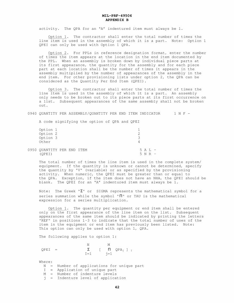
MIL-PRF-49506APPENDIX B
42
activity. The QPA for an “A” indentured item must always be 1.
Option 1. The contractor shall enter the total number of times the line item is used in the assembly of which it is a part. Note: Option 1 QPEI can only be used with Option 1 QPA.
Option 2. For PPLs in reference designation format, enter the number of times the item appears at the location in the end item documented by the PPL. When an assembly is broken down by individual piece parts at its first appearance, the quantity for the assembly and for each piece part at each location shall be the number of times it appears in the assembly multiplied by the number of appearances of the assembly in the end item. For other provisioning lists under option 2, the QPA can be considered as the Quantity Per End Item (QPEI).
Option 3. The contractor shall enter the total number of times the line item is used in the assembly of which it is a part. An assembly only needs to be broken out to its piece parts at its first occurrence on a list. Subsequent appearances of the same assembly shall not be broken out. 0940 QUANTITY PER ASSEMBLY/QUANTITY PER END ITEM INDICATOR 1 N F -
A code signifying the option of QPA and QPEI
Option 1 1 Option 2 2 Option 3 3 Other 4
0950 QUANTITY PER END ITEM 5 A L - (QPEI) 5 N R -
The total number of times the line item is used in the complete system/ equipment. If the quantity is unknown or cannot be determined, specify the quantity by "V" (variable) or as specified by the provisioning activity. When numeric, the QPEI must be greater than or equal to the QPA. Exception, if the item does not have an NHA, the QPEI should be blank. The QPEI for an “A” indentured item must always be 1.
Note: The Greek " Σ" or SIGMA represents the mathematical symbol for a series summation while the symbol " Π" or TAU is the mathematical expression for a series multiplication.
Option 1. The quantity per equipment or end item shall be entered only on the first appearance of the line item on the list. Subsequent appearances of the same item should be indicated by printing the letters "REF" in positions 1-3 to indicate that the total number of uses of the item in the equipment or end item has previously been listed. Note: This option can only be used with option 1, QPA.
The following applies to option 1:
N M QPEI = Σ [ Π QPA j ] I
I=1 j=1
Where: N = Number of applications for unique part I = Application of unique part M = Number of indenture levels j = Indenture level of application

MIL-PRF-49506APPENDIX B
43
Option 2. The QPEI shall be entered only on the first appearance of the item on the list. Subsequent appearances of the same assembly or subassembly should be indicated by printing "REFX" in positions 1-4. Subsequent appearances of the same repair part (i.e., a part which has no lower indentured parts) should be indicated by printing the letters "REF" in positions 1-3. This option can only be used with option 2, QPA.
Examples of provisioning lists with a single assembly breakdown using the option 2 QPA follow: Note that a separate application (PLISN and IPC) is required for each identical item in the same NHA.
1. For Reference Designation (RD) oriented equipment.
RD Reference No. QPA QPEI 1A1 ABC 0003 0003 1A1 R1 PDQ 0003 0006 1A1 R2 PDQ 0003 REF 1A1 MP2 XYZ 0006 0006 1A2 ABC 0000 REFX 1A3 ABC 0000 REFX
2. For nonreference designation oriented equipment:
Indenture Code Reference No. QPA QPEI
B ABC 0001 0003 C PDQ 0003 0006 C PDQ 0003 REF C XYZ 0006 0006 B ABC 0001 REFX B ABC 0001 REFX
The following applies to option 2:
N QPEI = Σ QPAi I=1
Where: N = Number of applications for unique part I = Application of unique part
Option 3. The QPEI shall be entered only on the first appearance of the line item on the list for system/equipment for which the list is prepared, and should equal the total number of appearances of the item in that system/equipment (all appearances of an item may not appear on the list). Subsequent appearances of the same assembly or subassembly should be indicated by printing "REFX" in positions 1-4. Subsequent appearances of the same repair part (i.e., a part which has no lower indentured parts) should be indicated by printing the letters "REF" in positions 1-3. This option can only be used with option 3 of the QPA.
The following applies to option 3:
N M P-1 Q QPEI = Σ [ [ Π QPAj ]I + Σ [ Π QPA1]k]i I=1 j=1 k=1 l=1
Where: N = Number of applications of unique part (first appearance of NHA
MIL-PRF-49506APPENDIX B
44
only) I = Application of unique part M = Number of indenture levels j = Indenture level of application at first appearance P = Number of applications of unique assembly containing unique part k = Application of unique part (other than first appearance of a higher assembly) Q = Number of indenture levels at assembly application (other than first appearance of a higher assembly) l = Indenture level of application (other than first appearance of a higher assembly)
Note: The first product and summation in this formula are performed against the first appearance of an item. These applications are documented in the hardware breakdown. The second product and summa- tion are performed against subsequent appearances of an item which are not documented. These item applications are identified by the first appearance of the item in an assembly (either NHA or higher) and the reference number of the higher assembly containing the unique part appearing in multiple applications.
0960 QUANTITY PER FIGURE 3 N R -
The total quantity of an item which is depicted by a specific illustration. Quantity per figure is left blank, if the quantity per assembly equals the quantity per figure.
0970 QUANTITY PER TEST 3 N R -
The number of end article system(s)/subsystem(s) or components required to enable the SE end item to perform properly (e.g., other components/ subsystems may be required to be intact in order to use the SE).
0980 QUANTITY PER UNIT PACK 3 N R - 3 A F -
The number of units of an item packaged as a unit pack (see MIL-STD-2073 for codes and explanations).
0990 QUANTITY PROCURED 6 N R -
The total quantity of the provisioned item order.
1000 QUANTITY SHIPPED 6 N R -
The quantity of items affected by the design change notice that have been shipped.
1010 RECOMMENDED MINIMUM SYSTEM 3 N R - STOCK LEVEL
A numeric value representing the recommended minimum level of system stock required to support initial deployment of a system/equipment.
1020 RECURRING COST 8 N R -
The cost which is subsequent to technical data package availability and does not include developmental costs.
1030 REFERENCE DESIGNATION 64 X L -
Letters or numbers, or both, used to uniquely identify and locate
MIL-PRF-49506APPENDIX B
45
discrete units, portions thereof, and basic parts of a specific component. The reference designation should result in the arrangement of provisioning lists for electronic and electronic related equipment being in alphanumeric reference designation order IAW IEEE 200-75, or in top-down or disassembly order as directed by the requiring authority. Parts for which reference designations have not been assigned, and for which disassembly sequencing is not possible, shall be listed in alpha - numeric part number or related data sequence. (Note: Compression (gang listing) of reference designations under one PLISN: Identical items identified by separate reference designators shall not be combined under a single PLISN unless authorized by the requiring authority.) For commercially designed, controlled, and commercially available electronic equipment, compliance with IEEE 200-75 is desired, but not mandatory. For reference designation oriented equipment, the reference designation shall be developed IAW IEEE 200-75, utilizing option 1 or 2 as prescribed by the requiring authority.
Option 1. Unit Numbering Method. When the unit numbering method is used, unit and subassembly portion (prefix) of the reference designation shall consist of up to 19 positions. The first 19 positions relate to assemblies and subassemblies.
Option 2. Block Numbering Method. When the block numbering method is used, the Joint Electronics Type Designation System (JETDS) nomenclature (type designation) for the unit shall be entered IAW the block numbering method. For nonelectronic items appearing in electronic equipment, use the identifying number or other symbol used to identify the item (e.g., figure and item number, up to 29 positions).
For nonreference designation oriented equipment, the requiring authority may request one of the following options be used:
Option 3. The volume, figure, and item number from the equipment technical manual will be used in lieu of the reference designation.
Option 4. The plan and piece number (drawing and piece identification) shall be used in lieu of the reference designation.
Option 5. The first precedence reference number.
1040 REFERENCE DESIGNATION CODE (RDC) 1 A F -
A code which indicates the type of data entered in reference designation block.
Assemblies that are separable or reparable A identified with a reference designation IAW IEEE 200-75 (does not apply to detail parts within the assembly).
Same as A, except this code is to be assigned U to assemblies that are inseparable or nonreparable.
Items identified with a volume, figure, and index F number in the reference designation block.
Installation and checkout items that are C inseparable or nonreparable.
Installation and checkout items that are Z separable or reparable.

MIL-PRF-49506APPENDIX B
46
Equipment assemblies/subassemblies identified H by drawing or assembly part numbers, with parts identified by circuit reference designator, number, part number or ship’s plan and piece number.
Repairable accessories, tools, test, and T SE identified as specified for Code "H".
Repairable accessories, nonrepairable R assemblies, and material, including common and bulk items, not required to be identified with reference designation.
Nonrepairable accessories, tools, test S and SE not included in code "T" breakdown.
1050 REFERENCE NUMBER 32 X L -
Any number, other than a government activity stock number, used to identify an item of production, or used by itself or in conjunction with other reference numbers to identify an item of supply. Reference numbers include part or identifying number, drawing, model, type, item designator or source controlling numbers; manufacturer’s trade name; specification or standard numbers; and specification or standard part, drawing, or type numbers (for applicable formats see DOD 4100.39-M). The following precedence for reference number assignment should be used:
a. First Precedent Reference Number. The line item is identified by a government or industry association’s specifications, drawing, or standard number, e.g., FED, MIL, JAN, AN, NEMA, SAE, which completely identifies the item including its physical, mechanical, electrical, and dimensional characteristics. (If the government or industry association’s specification or standard number does not fully identify the item, then the actual manufacturer's identifying reference number becomes the first precedent reference number.) If the government or industry specification, drawing, or standard completely identifies the item, at least one additional reference number citing a manufacturer or vendor reference number must be provided.
b. Second Precedent Reference Number. When the line item is identified as, "source control," "altered," or "selected" (MIL -T-31000), the contractors assigned number is used.
c. Third Precedent Reference Number. The item identifying part, drawing, or catalog number of the actual manufacturer who supplies the item. The manufacturer is the company or government activity exercising design control over the item.
REFERENCE NUMBER - AID. A reference number of the adapter/interconnector device used in conjunction with the SE.
REFERENCE NUMBER - ARN ITEM. A reference number of the primary item under analysis.
REFERENCE NUMBER - ARTICLE REQUIRING SUPPORT. A reference number of the article requiring support.
REFERENCE NUMBER - AUTOMATIC TEST EQUIPMENT. A reference number of the ATE.

MIL-PRF-49506APPENDIX B
47
REFERENCE NUMBER - CATEGORY III SE. A reference number of the SE that is measuring the SE UUT. REFERENCE NUMBER - SUPPORT EQUIPMENT. A reference number of the SE under analysis.
REFERENCE NUMBER - TEST PROGRAM SETS. A reference number of the test program sets being used in conjunction with the SE.
REFERENCE NUMBER - UUT. The reference number of the UUT which is identical to the piece of SE.
REFERENCE NUMBER (ARN) - ADDITIONAL. A drawing or interchangeable reference number related to the reference number of the item under
analysis. Only those ARNs that are known and available as a result ofthe contractor’s design and production experience should be provided.This requirement is not intended to burden the contractor with theadditional work load of searching for ARNs. When more than one
manufacturer’s reference number identifies a single design item, the additional reference number(s) which have been validated by the contractor as completely interchangeable for the specific application and whose use will not invalidate the end item warranty shall be furnished.
1060 REFERENCE NUMBER CATEGORY CODE (RNCC) 1 X F -
A code assigned to the reference number to indicate the category or relationship of the number to an NSN or another reference number (for applicable codes see DOD 4l00.39-M).
RNCC - ARN. The code assigned to the additional reference number.
1070 REFERENCE NUMBER VARIATION CODE 1 N F - (RNVC)
A code assigned to a reference number to indicate that the cited number is item identifying, is not item identifying or is a reference number for information only (for applicable codes see DOD 4l00.39-M).
RNVC - ARN. The code assigned to the additional reference number.
1080 REPAIR CYCLE TIME 18 N - -
The elapsed time, in days, of the complete repair cycle for a reparable item expected at each maintenance level. The subfield values must be either blank or greater for each higher O/M level. The O/M levels in ascending order are O/F/H/L/D and Contractor.
a. First Subfield 3 N R -
Repair Cycle Time at Organizational/On Equipment/Unit-Organizational level.
b. Second Subfield 3 N R -
Repair Cycle Time at Intermediate/Direct Support/Afloat/Third Echelon/Off Equipment/Intermediate-Forward level.
c. Third Subfield 3 N R -
Repair Cycle Time at Intermediate/General Support/Ashore/Fourth Echelon/ Intermediate-Rear level.

MIL-PRF-49506APPENDIX B
48
d. Fourth Subfield 3 N R -
Repair Cycle Time at Specialized Repair Activity (SRA).
e. Fifth Subfield 3 N R -
Repair Cycle Time at Depot/Shipyard.
f. Sixth Subfield 3 N R -
Contractor. An expressed period of time measured in days from receipt of a failed item at the contractor’s facility until the item is returned to the designated receiving point (e.g., repair cycle time at contractor facility).
Option 1.
a. For O, F, H, and SRA, the elapsed time in days, beginning with the removal and replacement of an item to be repaired below depot level, and ending with the pickup of the serviceable item on the appropriate supply records.
b. For D, the number of days includes the time involved in the following:
(1) Removal and preparation of unserviceable items for shipment to CONUS air terminal or oversea aerial port.
(2) Shipment to air terminal/aerial port.
(3) Shipment from aerial port of embarkation to CONUS aerial port of disembarkation (oversea activities only). This entry should be weighted if the item is applicable to a variety of activities.
(4) Shipment from CONUS air terminal/aerial port to CONUS depot level maintenance activity.
(5) Receiving/shop planning/batching.
(6) Shop flow-time, including inspection.
(7) Packaging.
(8) Pickup on accountable records.
c. For contractor repairable items, the elapsed time in days from time of receipt of the failed item at the contractor’s facility, until the item is returned to the designated receiving point.
Option 2. The elapsed time in days from receipt of a failed item at the maintenance level, until the item is ready for issue as a serviceable item.
1090 REPLACED OR SUPERSEDING 5 X L - PROVISIONING LIST ITEM SEQUENCE NUMBER
The PLISN which is replacing or is being replaced in relationship to another PLISN.
1100 REPLACED OR SUPERSEDING 1 A F - PROVISIONING LIST ITEM SEQUENCE NUMBER

MIL-PRF-49506APPENDIX B
49
INDICATOR (RS/IND)
A code to indicate type of data entered in the Replaced or Superseding PLISN.
Replaced PLISN R Superseding PLISN blank
1110 REPLACEMENT TASK DISTRIBUTION 15 N - -
The estimated percentage of the removals and replacements of an item that will be accomplished at each specified maintenance level. The sum of all subfields will always total 100 percent.
a. First Subfield 3 N R -
Replacement Task Distribution at Organizational/On Equipment/Unit- Organizational level.
b. Second Subfield 3 N R -
Replacement Task Distribution at Intermediate/Direct Support/Afloat/Third Echelon/Off Equipment/Intermediate-Forward level.
c. Third Subfield 3 N R -
Replacement Task Distribution at Intermediate/General Support/Ashore/ Fourth Echelon/Intermediate-Rear level.
d. Fourth Subfield 3 N R -
Replacement Task Distribution at SRA.
e. Fifth Subfield 3 N R -
Replacement Task Distribution at Depot/Shipyard.
1120 REVISION 2 A R -
An alphabetic code of one or two positions identifying a revision, such as A, B, ..., ZZ.
REVISION - SERD. A revision of the SERD.
1130 REWORK REMOVAL RATE (RRR) 3 N R 2
The percentage of the total quantity of a repairable assembly installedin an end item which will require some depth of rework concurrently withthat end item.
1140 ROTATABLE POOL FACTOR (RPF) 6 N R 3
The predicted number of times in one maintenance cycle that an item isremoved from its next higher assembly at the Organizational/Intermediatelevels of maintenance, repaired at the Intermediate level and returnedto stock at that level. The calculation for RPF maybe computed as
follows:
RPF = [MTD(F) + MTD(H)] X MRRI
Legend: MTD = Maintenance Task Distribution (DPD# 0580)
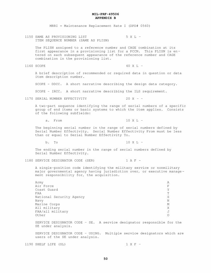
MIL-PRF-49506APPENDIX B
50
MRRI = Maintenance Replacement Rate I (DPD# 0560)
1150 SAME AS PROVISIONING LIST 5 X L - ITEM SEQUENCE NUMBER (SAME AS PLISN)
The PLISN assigned to a reference number and CAGE combination at its first appearance in a provisioning list for a PCCN. This PLISN is en- tered on each subsequent appearance of the reference number and CAGE combination in the provisioning list.
1160 SCOPE 40 X L -
A brief description of recommended or required data in question or data item description number.
SCOPE - DDCC. A short narrative describing the design data category.
SCOPE - IRCC. A short narrative describing the ILS requirement.
1170 SERIAL NUMBER EFFECTIVITY 20 X - -
A two-part sequence identifying the range of serial numbers of a specific group of end items or basic systems to which the item applies. Consists of the following subfields:
a. From l0 X L -
The beginning serial number in the range of serial numbers defined by Serial Number Effectivity. Serial Number Effectivity From must be less than or equal to Serial Number Effectivity To.
b. To l0 X L -
The ending serial number in the range of serial numbers defined by Serial Number Effectivity.
1180 SERVICE DESIGNATOR CODE (SER) 1 A F -
A single-position code identifying the military service or nonmilitary major governmental agency having jurisdiction over, or executive manage - ment responsibility for, the acquisition.
Army A Air Force F Coast Guard Y FAA T National Security Agency S Navy N Marine Corps M All military X FAA/all military J Other O
SERVICE DESIGNATOR CODE - SE. A service designator responsible for the SE under analysis.
SERVICE DESIGNATOR CODE - USING. Multiple service designators which are users of the SE under analysis.
1190 SHELF LIFE (SL) 1 X F -

MIL-PRF-49506APPENDIX B
51
A code assigned to an item to indicate a storage or SL time period for an item possessing deteriorative or unstable characteristics (see DOD 4l00.39-M for applicable codes).
1200 SHELF LIFE ACTION CODE (SLAC) 2 X F -
A two-position code assigned to a SL item to specify the type of inspection, test, or restorative action to be taken when the item has reached its storage SL, and to specify the extension of the SL time period after the test/restorative action has been completed.
Check/inspect/test IAW CO inventory managers instructions.
Incorporate all mandatory changes. If found C- satisfactory, extend the previously established shelf life by an appropriate time period. The first position will always be "C". The second position, shown by a dash (-), will be filled in with a shelf life code from DOD 4100.39-M. This code will be used to indicate the time period that the shelf life may be extended after incorporation of the changes.
Incorporate all mandatory changes, perform CT minor adjustment required, clean and relubricate bearings, reassemble, test to post overhaul standards, and correct any observed discrepancies. Items which pass tests shall be returned to stock as RFI (Ready For Issue). Exterior package marking of such items shall indicate the latest check and test date and the original date of manufacture. Items which fail test shall be placed in "F" condition.
To be tested by the laboratory/activity L- after the initial shelf life has expired and at specified time intervals thereafter. The first position will always be "L". The second position, shown by a dash(-), will be filled in with a shelf life code from DOD 4l00.39-M. This code will be used to indicate the time period at which samples should be periodical- ly submitted to the laboratory/activity for testing after the initial shelf life has expired. If item fails test, take disposal action.
Replace all deteriorated and nonmetallic RD components subject to deterioration (disassemble and process to the level required to permit replacement of deteriorable items; test to post-overhaul standards and return to stock as RFI item with fully restored storage time limitations). Exterior package marking of such items shall indicate the latest date of overhaul.
This is assigned to fuel metering equipment, RJ which has been tested by other than MIL-C-7024.

MIL-PRF-49506APPENDIX B
52
Provides for equipment that has been tested RN with fluids indicated by Specification MIL-C-7024 and has not subsequently been operated with other fluids. (Use for fuel metering equipment only.)
Salvage SA
Request cannibalization/salvage instructions SB from inventory manager.
Identification of Safety Items. A safety S9 item designated by the requiring authority that is subject to a 5 year age limitation when used for purposes involving safety of personnel. Material in this category that is over 5 years old will not be used for repair or modification of personnel, drag, or special parachutes, or others used directly involving personnel safety. Use advice code 2H unless material is being used for cargo parachutes, or other uses not involving personnel safety.
Test, if OK, extend previously established T- shelf life by an appropriate time period and process IAW with code RD. The first position will always be "T". The second position, shown by a dash (-), will be filled in with a shelf life code from DOD 4l00.39-M. This code will be used to indicate the time period that the shelf life may be extended after passing test and processing IAW code RD. NOTE: For flight clothing, the second position of the code will be used to indicate the time interval at which periodic testing should be performed. If OK, return to stock as an RFI item; if not OK, make necessary repairs to the extent economically feasible and return to stock as RFI item.
Unsuitable for restoration to issuable status. UU At end of shelf life period, material will be disposed of IAW existing instructions.
Test. If item passes a test, extend the X- previously established shelf life by an appropriate time period. The first position will always be "X". The second position, shown by a dash (-), will be filled in with a shelf life code from DOD 4l00.39-M. This code will be used to indicate the time period that the shelf life may be extended. If item fails tests, dispose of it IAW existing instructions.
Non-deteriorative. When the shelf life is coded 0, 00 then the shelf life action code of 00 is mandatory.
1210 SKILL SPECIALTY CODE FOR SUPPORT 7 X L EQUIPMENT OPERATOR
Describes the maintenance or operator skill required to operate the SE under analysis. See the requiring authority for a list of possible codes.

MIL-PRF-49506APPENDIX B
53
1220 SOURCE, MAINTENANCE AND 6 X L - RECOVERABILITY (SMR) CODE
SMR codes are a series of alpha or alphanumeric symbols used at the time of provisioning to indicate the source of supply of an item, its main- tenance implications, and recoverability characteristics. Applicable codes are specified in the joint regulation AR 700-82, OPNAVINST 4410.2, AFR 66-45, MCO 4400.120, DSAR 4100.6 publication.
1230 SPARES ACQUISITION INTEGRATED WITH 1 A F - PRODUCTION (SAIP)
An alphabetic code indicating that the item is a candidate for an SAIP list.
Item is an SAIP list candidate Y Item is not an SAIP list candidate blank
1240 SPECIAL MAINTENANCE ITEM CODE (SMIC) 1 A F -
Codes which indicates any special maintenance category applicable to the line item. Codes assigned are as follows:
Nonrepairable A
Factory repairable B
Matched set C
Select at test D
MAMS (Maintenance Assistance Modules). An item F authorized or recommended by the government/ contractor for procurement and location with the end item as the sole means of fault isolation in the event of failure. Contractor recommendations shall be IAW the maintenance philosophy approved by the government. (e.g., modules employed in diagnostic circuitry used for "built-in" fault isolation.)
Remain in Place. A repairable item which, upon G removal without an immediate replacement, would: a. Destroy structural integrity; b. Endanger operating or maintenance personnel; or c. If partially degraded, cause total degrad- ation of an essential function of the end item.
Safety. An item which, upon failure, would H jeopardize the direct safety of operating or maintenance personnel.
Flight critical. The single failure of which, during J any operating condition could cause loss of the aircraft or one of its major components, loss of control,
unintentional release of, or inability to release any armament store, failure of weapon installation components, or which may cause significant personnel injury, including during launch or recovery, flight, escape, survival, or rescue.

MIL-PRF-49506APPENDIX B
54
1250 SPECIAL MARKING CODE 2 X F -
A code which identifies special markings which are required as an integral part of the total pack to protect the contained item during preservation, packing, storage, transit, and removal from the pack. For applicable codes, see MIL-STD-2073.
1260 SPECIAL MATERIAL CONTENT CODE 1 X F - (SMCC)
A code indicating that an item represents or contains peculiar material requiring special treatment, precautions, or management control of the item (see DOD 4l00.39-M for applicable codes).
1270 SPECIAL PACKAGING INSTRUCTION l0 X L - NUMBER
A number which identifies a specific special packaging instruction prepared IAW MIL-STD-2073.
1280 SPECIAL PACKAGING INSTRUCTION (SPI) 1 A F - NUMBER REVISION
A code which identifies the SPI revision.
Codes A through Z
1290 SUPPLEMENTAL PACKAGING DATA 59 X L -
Concise remarks or statements which are pertinent to the packaging pro - cess and are required in addition to that specific data documentation.
1300 SUPPORT EQUIPMENT DIMENSIONS 12 N - AS
The dimensions of an item of support/test equipment. Consists of the following subfields:
a. Length 4 N R 1
b. Width 4 N R 1
c. Height 4 N R 1
SE DIMENSIONS OPERATING. Dimensions of an item of support/test equipment or training material while it is in the operational configuration mode.
SE DIMENSIONS SHIPPING. The dimensions of an item of support/test equipment as it is configured for shipment.
SE DIMENSIONS STORAGE. Dimensions of an item of support/test equipment or training material while it is in the storage configuration mode.
1310 SUPPORT EQUIPMENT EXPLANATION - - - -
Narrative statements used to explain a condition not readily identified in a given data product within the support equipment area, or a particular product which requires additional comment. When the information is related to a specific data product, the explanation should be prefaced with a reference to that product.
1320 SUPPORT EQUIPMENT RECOMMENDATION 10 X L -

MIL-PRF-49506APPENDIX B
55
DATA NUMBER (SERD NUMBER)
A code assigned to identify a piece of support equipment having a unique Reference Number and Commercial and Government Entity (CAGE) Code.
1330 SUPPORT EQUIPMENT RECOMMENDATION - - - - DATA REVISION/SUPERSEDURE REMARKS
Identify the reason for supersedure or revision for the SE.
1340 SUPPORT EQUIPMENT WEIGHT 6 N R 1
The weight of an item of support/test equipment.
SE WEIGHT OPERATING. The operating weight of the item under analysis.
SE WEIGHT SHIPPING. The weight of an item of support/test equipment as configured for shipment.
SE WEIGHT STORAGE. The weight of an item of support/test equipment or training material while it is in the storage configuration mode.
1350 TECHNICAL MANUAL CHANGE NUMBER 2 N R - (TM CHG)
A change number reflecting the current edition of a specific manual.
1360 TECHNICAL MANUAL INDENTURE CODE 1 N F - (TM IND)
A code used to indent item names in the repair part description column in a manual to depict disassembly parts relationship within a figure of the text. Codes are: "1" through "5", which indents the item in the parts manual listing by the number specified.
1370 TECHNICAL MANUAL NUMBER 30 X L -
The technical manual, technical order, or manual controlling number assigned by the requiring authority.
1380 TEST ACCURACY RATIO (TAR) 1 X F -
A one-position code specifying a ratio. The TAR is determined by dividing the maximum permitted error of the unit to be measured or calibrated by the maximum known error of the measuring or generating device used to perform the measurement.
TAR Greater Than or Equal To Code
1:1 1 2:1 2 3:1 3 4:1 4 5:1 5 6:1 6 7:1 7 8:1 8 9:1 9 10:1 0
TEST ACCURACY RATIO - CATEGORY III SE. The actual TAR of the TMDE in conjunction with the SE UUT.

MIL-PRF-49506APPENDIX B
56
TEST ACCURACY RATIO - UUT PARAMETER. The actual TAR of the TMDE in conjunction with the UUT.
1390 TOTAL ITEM CHANGES 2 N R - (TIC)
The number of times the item is affected by the design change or the cumulative total number of design changes affecting the item.
Option 1. The total number of times the line item is affected by the design change.
Option 2. The cumulative total number of design changes affecting the PLISN.
1400 TOTAL QUANTITY RECOMMENDED 6 N R -
A recommended quantity of an item required to support a specific number of applications for a specific period of time. The applications may be to a weapon system, end item, component or combinations thereof, which are contained in the applicable contract.
1410 TYPE EQUIPMENT CODE 4 X L -
A government supplied code identifying an end item in the maintenance data collection subsystem (MDCS) by its application to the specific type/model/series of aircraft or equipment which it supports.
1420 TYPE OF CHANGE CODE (TOCC) 1 A F -
This block, which is blank on initial submissions of provisioning data, shall be used as a type of change code to indicate deletions, modifications, typographical errors, quantity changes (increase, decrease), and limited part applications as follows:
Indicates a deleted item D Deletion of a data product G Item is replaced during production and L support of the old part may be required for prior production quantities Indicates a modified item. Required to M identify entries for those items changed as a result of either administrative or engineering requirements (not for initial entry of NSN) before or during production.
Examples of changes follow:
a. Prime contractor’s reference number b. Commercial and Government Entity Code c. Manufacturer’s reference number d. Item name e. Other data products as may be subsequently defined, wherein the hardware is not affected.
Used to make quantity field changes Q Used to make a typographical error correction (not automatic- T ally assigned)
1430 TYPE OF PRICE CODE 1 A F -

MIL-PRF-49506APPENDIX B
57
A code used to define the type of UM or UI Price.
Engineering estimate A Federal catalog price B Vendor catalog price C Negotiated price D
1440 TYPE OF STORAGE CODE 1 A F -
Indicates the type of storage space and environmental conditions to bemaintained during storage or shipment. (See NAVSUP PUB 437,appendix 17, page 91, for specific usage.)
General purpose, unheated A General purpose, heated B General purpose, controlled humidity (maximum 40% RH ashore; C as dry as possible afloat) Heavy duty, unheated (overhead crane area) - over 100 cf D or 1000 lbs Heavy duty, heated (overhead crane area) E Heavy duty, controlled humidity (overhead crane area) F Flammable G Freeze (below 32 F) H Chill (between 32 F and 50 F) I Shed J Open K Explosive storage (non-ordnance items, such as explosive L bolts and rivets) Acid storage M Inert compressed gas storage (Naval Ships Technical Manual, N chapter 9230, sections 23 and 24, provide stowage requirements and safety precautions for compressed gases) Special storage (requires specific authority and stowage O instructions) Separate storage (fire producers, not elsewhere classified; P keep away from acid, combustible, organic, and readily oxidizable materials) Warehouse/flammable storage (prohibited for shipment storage) Q Warehouse/general storage (no special requirements; R prohibited for shipboard storage) Warehouse/special storage (requires specific authority and S storage instructions; prohibited for shipboard storage) Warehouse/separate storage (fire producers; keep away from T acid, combustible, organic, and readily oxidizable materials; prohibited for shipboard storage) Flammable compressed gas storage (Naval Ships Technical U Manual, chapter 9230, sections 23 and 24, provides stowage requirements and safety requirements for compressed gases) Oxidizing compressed gas storage (Naval Ships Technical V Manual, chapter 9230, sections 23 and 24, provides stowage requirements and safety requirements for compressed gases) Poisonous compressed gas storage (Naval Ships Technical W Manual, chapter 9230, sections 23 and 24, provides stowage requirements and safety requirements for compressed gases) Radioactive material. Store in a designated radioactive X material area in accordance with afloat supply procedures, NAVSUP PUB 485.
NOTE: When one of certain Special Material Content Codes is assigned, the entry of a corresponding Type of Storage Code is required in accordance with the following table:

MIL-PRF-49506APPENDIX B
58
Special Material Content Code Type of Storage Code B U, V, or W C, E, I, J, M, S, T, U or Y O F, G, or Z G P O or W Q L R X W V, W, or N X O or X
1450 UNIT CONTAINER CODE 2 X F -
A code to identify the container used to hold the quantity unit pack. For applicable code, see MIL-STD-2073.
1460 UNIT CONTAINER LEVEL 1 A F -
A code which indicates the highest level of packing protection provided by the unit container.
Unit container not acceptable for shipping. O Unit container acceptable and provides A level "A" protection.
Unit container acceptable and provides B level "B" protection.
Unit container acceptable and provides C level "C" protection.
Unit container not required. D
Unit container is acceptable and provides X minimum protection with commercial packaging.
Unit container is acceptable and affords, Z or is limited to, special consideration (e.g., air only, inside storage only).
1470 UNIT OF ISSUE (UI) 2 A F -
A code which indicates the UI quantity of an item. The UI quantity is the managing activity’s established accounting unit upon which the smallest unit pack is based, accountable records are maintained, and requirements are computed. For applicable codes see DOD 4l00.39-M.
1480 UNIT OF ISSUE CONVERSION FACTOR 5 N - - (UI CONVERSION FACTOR)
A quantitative multiplier used to convert the UM to the UI. The data product is composed of two subfields:
a. First Digit. Decimal Locator 1 N F - Code
A digit (0, l, 2, 3, or 4) indicating the number of places that the decimal must be moved from the right most position of the second subfield to describe correct decimal placement in that field.
b. Digits 2 through 5. Factor 4 N R AS

MIL-PRF-49506APPENDIX B
59
The numerical value of the conversion factor.
1490 UNIT OF ISSUE/UNIT OF MEASURE CODE 1 A F -
A code that identifies the associated information as either UI or UM related.
Unit of Measure M Unit of Issue I
1500 UNIT OF ISSUE/UNIT OF MEASURE PRICE 10 N R 2 (UI/UM PRICE)
The price for one UI of an item or the best estimated price per UM. The last two positions of the field represent cents, and the decimal is understood.
1510 UNIT OF MEASURE (UM) 2 A F -
The UM, as defined in DOD 4l00.39-M. The UM is abbreviated: dz, ea, ft, gl, in, lb, oz, etc., for dozen, each, foot, gallon, inch, pound, ounce, etc., respectively.
UNIT OF MEASURE - SE OPERATING DIMENSIONS. A UM associated with the length, width, and height of the SE in operational mode.
UNIT OF MEASURE - SE OPERATING WEIGHT. A UM associated with the weight of the SE in operational mode.
UNIT OF MEASURE - SE STORAGE DIMENSIONS. A UM associated with the length, width, and height of the SE in the storage mode.
UNIT OF MEASURE - SE STORAGE WEIGHT. A UM associated with the weight of the SE in the storage mode.
UNIT OF MEASURE - SUPPORT EQUIPMENT SHIPPING DIMENSIONS. A UM associated with the length, width, and height of the SE in the shipping mode.
UNIT OF MEASURE - SUPPORT EQUIPMENT SHIPPING WEIGHT. A UM associated with the weight of the SE in the shipping mode.
1520 UNIT PACK CUBE 7 N R 3
The length times width times depth (or cubic dimensions) of the unit container expressed in feet.
1530 UNIT SIZE 12 N - -
The length, width, and height of the item, as configured for packaging, expressed in inches. Subfields are as follow:
a. Length 4 N R l
b. Width 4 N R l
c. Height/Depth 4 N R l
UNIT SIZE - PACK. The length, width, and depth of the unit container or package expressed in inches. The unit pack size must be greater than or equal to unit size

MIL-PRF-49506APPENDIX B
60
1540 UNIT UNDER TEST EXPLANATION 240 x L -
Narrative statements which further explain, justify, or substantiate any data entry concerning UUT related data.
1550 UNIT WEIGHT 5 X - -
The unpackaged weight of the item expressed in pounds. The field is structured as follows:
a. For weights up to 9,999.9 5 N R l
b. For weights over 9,999.9 5 X - -
First subfield. l A F -
Multiplier code indicates that the number entered in the second subfield should be multiplied by l0, 100, or l,000 in order to correctly represent the unit weight. Codes are as follow:
l0 X weight A l00 X weight B l000 X weight C
Second subfield. 4 N R AS
Numerical values of the weight expressed in pounds.
UNIT WEIGHT - PACK. The gross weight of the unit pack expressed in pounds. Unit pack weight must be greater than or equal to unit weight.
1560 USABLE ON CODE (UOC) 4 X L -
A code that indicates the configuration of a system/equipment on which the item under analysis is used. The UOC represents only one configura - tion/model of equipment. It is a one, two, three, or four-character alphanumeric entry with guidance for UOC assignment provided by the requiring authority.
USABLE ON CODE - DESIGN CHANGE. The UOCs affected by the design change.
USABLE ON CODE - SUPPORT EQUIPMENT. The UOCs of the SE.
1570 WEAROUT LIFE 6 N R -
The operational interval of flight hours, calendar time, or other appropriate, independent variables, from initial installation until an item can no longer perform its intended mission, due to the depletion of some physical property or material. For a family of items, wearout occurs when the conditional probability of failure (hazard rate) increases with increases of the independent variable.
1580 WORK UNIT CODE 7 X L -
An alphanumeric code used to identify a particular system, subsystem, component/assembly, or part of the system/equipment. Codes will be as specified by the requiring authority. WORK UNIT CODE - ARTICLES REQUIRING SUPPORT. A code used to identify the article requiring support.
1590 WRAPPING MATERIAL 2 X F -

MIL-PRF-49506APPENDIX B
61
A code which indicates the type of wrapping material to be used on the item. For applicable codes, see MIL-STD-2073.
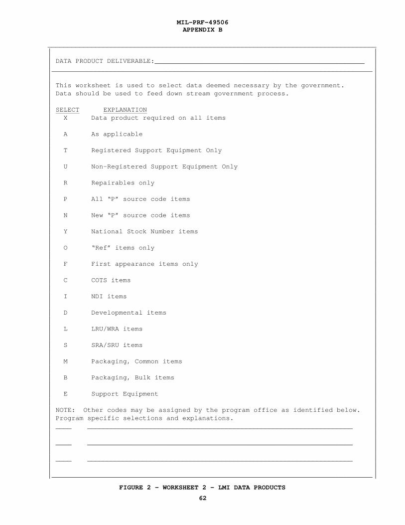
MIL-PRF-49506APPENDIX B
FIGURE 2 - WORKSHEET 2 - LMI DATA PRODUCTS
62
___________________________________________________________________________________* ** DATA PRODUCT DELIVERABLE:_____________________________________________________ **_________________________________________________________________________________ ** ** This worksheet is used to select data deemed necessary by the government. ** Data should be used to feed down stream government process. ** ** SELECT EXPLANATION ** X Data product required on all items ** ** A As applicable ** ** T Registered Support Equipment Only ** ** U Non-Registered Support Equipment Only ** ** R Repairables only ** ** P All “P” source code items ** ** N New “P” source code items ** ** Y National Stock Number items ** ** O “Ref” items only ** ** F First appearance items only ** ** C COTS items ** ** I NDI items ** ** D Developmental items ** ** L LRU/WRA items ** ** S SRA/SRU items ** ** M Packaging, Common items ** ** B Packaging, Bulk items ** ** E Support Equipment ** ** NOTE: Other codes may be assigned by the program office as identified below. ** Program specific selections and explanations. ** ____ ___________________________________________________________________ ** ** ____ ___________________________________________________________________ ** ** ____ ___________________________________________________________________ ** **_________________________________________________________________________________ *
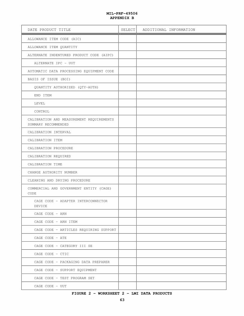
MIL-PRF-49506APPENDIX B
FIGURE 2 - WORKSHEET 2 - LMI DATA PRODUCTS
63
DATE PRODUCT TITLE SELECT ADDITIONAL INFORMATION
ALLOWANCE ITEM CODE (AIC)
ALLOWANCE ITEM QUANTITY
ALTERNATE INDENTURED PRODUCT CODE (AIPC)
ALTERNATE IPC - UUT
AUTOMATIC DATA PROCESSING EQUIPMENT CODE
BASIS OF ISSUE (BOI)
QUANTITY AUTHORIZED (QTY-AUTH)
END ITEM
LEVEL
CONTROL
CALIBRATION AND MEASUREMENT REQUIREMENTS
SUMMARY RECOMMENDED
CALIBRATION INTERVAL
CALIBRATION ITEM
CALIBRATION PROCEDURE
CALIBRATION REQUIRED
CALIBRATION TIME
CHANGE AUTHORITY NUMBER
CLEANING AND DRYING PROCEDURE
COMMERCIAL AND GOVERNMENT ENTITY (CAGE)
CODE
CAGE CODE - ADAPTER INTERCONNECTOR
DEVICE
CAGE CODE - ARN
CAGE CODE - ARN ITEM
CAGE CODE - ARTICLES REQUIRING SUPPORT
CAGE CODE - ATE
CAGE CODE - CATEGORY III SE
CAGE CODE - CTIC
CAGE CODE - PACKAGING DATA PREPARER
CAGE CODE - SUPPORT EQUIPMENT
CAGE CODE - TEST PROGRAM SET
CAGE CODE - UUT

MIL-PRF-49506APPENDIX B
FIGURE 2 - WORKSHEET 2 - LMI DATA PRODUCTS
64
CONTRACTOR FURNISHED EQUIPMENT/
GOVERNMENT FURNISHED EQUIPMENT (CFE/GFE)
CONTRACTOR RECOMMENDED
CONTRACTOR RECOMMENDED - DDCC
CONTRACTOR RECOMMENDED - IRCC
CONTRACTOR TECHNICAL INFORMATION CODE
(CTIC)
CONTROLLED INVENTORY ITEM CODE
CRITICALITY CODE
CUSHIONING AND DUNNAGE MATERIAL CODE
CUSHIONING THICKNESS
DEGREE OF PROTECTION CODE
DEMILITARIZATION CODE (DMIL)
DESCRIPTION/FUNCTION AND CHARACTERISTICS
OF SUPPORT EQUIPMENT
DESIGN DATA CATEGORY CODE
DESIGN DATA PRICE
END ITEM ACRONYM CODE (EIAC)
ESSENTIALITY CODE
ESTIMATED PRICE
ESTIMATED PRICE - DDCC
ESTIMATED PRICE - IRCC
FIGURE NUMBER
FRAGILITY FACTOR
FUNCTIONAL ANALYSIS
FUNCTIONAL GROUP CODE
HARDNESS CRITICAL ITEM (HCI)
HARDWARE DEVELOPMENT PRICE
HAZARDOUS CODE
INDENTURE CODE
ATTACHING PART/HARDWARE
OPTION 1
OPTION 2
OPTION 3

MIL-PRF-49506APPENDIX B
FIGURE 2 - WORKSHEET 2 - LMI DATA PRODUCTS
65
OPTION 4
OPTION 5
INDENTURE FOR KITS
OPTION 1
OPTION 2
OPTION 3
INDENTURE CODE - IPC
INDENTURED PRODUCT CODE (IPC)
INDENTURED PRODUCT CODE (IPC) - UUT
INPUT POWER SOURCE
OPERATING RANGE - MINIMUM
OPERATING RANGE - MAXIMUM
ALTERNATING CURRENT/DIRECT CURRENT
FREQUENCY RANGE - MINIMUM
FREQUENCY RANGE - MAXIMUM
PHASE
WATTS
PERCENT MAXIMUM RIPPLE
INSTALLATION FACTORS OR OTHER FACILITIES
INTEGRATED LOGISTIC SUPPORT PRICE
INTEGRATED LOGISTIC SUPPORT REQUIREMENTS
CATEGORY CODE
INTERCHANGEABILITY CODE
INTERMEDIATE CONTAINER CODE
INTERMEDIATE CONTAINER QUANTITY
ITEM CATEGORY CODE (ICC)
ITEM DESIGNATOR CODE
ITEM DESIGNATOR - END ARTICLE
ITEM DESIGNATOR - GOVERNMENT
ITEM NAME
ITEM NAME - ARTICLE REQUIRING SUPPORT
ITEM NAME - SE
ITEM NAME CODE

MIL-PRF-49506APPENDIX B
FIGURE 2 - WORKSHEET 2 - LMI DATA PRODUCTS
66
ITEM NUMBER
JULIAN DATE - SPI NUMBER
LINE REPLACEABLE UNIT (LRU)
LOT QUANTITY
FROM
TO
MAINTENANCE ACTION CODE (MAC)
MAINTENANCE REPLACEMENT FACTOR (MRF)
MRF - DEPOT LEVEL REPAIRABLES
MRF - FIELD LEVEL REPAIRABLES
MRF - CONSUMABLES
MAINTENANCE REPLACEMENT RATE I (MRRI)
MAINTENANCE REPLACEMENT RATE II (MRRII)
OPTION 1
OPTION 2
MAINTENANCE TASK DISTRIBUTION
MATERIAL
MATERIAL LEADTIME
MATERIAL WEIGHT
MAXIMUM ALLOWABLE OPERATING TIME (MAOT)
MEAN TIME BETWEEN FAILURES (MTBF)
MEAN TIME BETWEEN FAILURES (MTBF) -
SUPPORT EQUIPMENT
MEAN TIME TO REPAIR (MTTR)
MEAN TIME TO REPAIR (MTTR) - SE
MEASUREMENT BASE (MB)
MEASUREMENT BASE - MEAN TIME BETWEEN FAILURES
MEASUREMENT BASE - MEAN TIME BETWEEN FAILURES - SUPPORT EQUIPMENT
MEASUREMENT BASE - WEAROUT LIFE
METHOD OF PRESERVATION
MOBILE FACILITY CODE
NATIONAL STOCK NUMBER - CONTAINER

MIL-PRF-49506APPENDIX B
FIGURE 2 - WORKSHEET 2 - LMI DATA PRODUCTS
67
FEDERAL SUPPPLY CLASSIFICATION
NATIONAL ITEM IDENTIFICATION NUMBER
NATIONAL STOCK NUMBER AND RELATED DATA
COGNIZANCE CODE
MATERIEL CONTROL CODE
FEDERAL SUPPLY CLASSIFICATION
NATIONAL ITEM IDENTIFICATION NUMBER
SPECIAL MATERIEL IDENTIFICATION CODE/ MATERIEL MANAGEMENT AGGREGATION CODE
ACTIVITY CODE
NEXT HIGHER ASSEMBLY PROVISIONING LIST
ITEM SEQUENCE NUMBER (NHA PLISN)
NEXT HIGHER ASSEMBLY PROVISIONING LIST
ITEM SEQUENCE NUMBER INDICATOR (NHA IND)
NOT REPARABLE THIS STATION (NRTS)
OPERATOR’S MANUAL
OPTIONAL PROCEDURE INDICATOR
OVERHAUL REPLACEMENT RATE (ORR)
PACKAGING CATEGORY CODE
PACKING CODE
PARAMETERS
INPUT/OUTPUT CODE - CATEGORY III SE
PARAMETER - CATEGORY III SE
RANGE FROM - CATEGORY III SE
RANGE TO - CATEGORY III SE
ACCURACY - CATEGORY III SE
RANGE/VALUE CODE - CATEGORY III SE
INPUT/OUTPUT CODE - SUPPORT EQUIPMENT
PARAMETER - SUPPORT EQUIPMENT
RANGE FROM - SUPPORT EQUIPMENT
RANGE TO - SUPPORT EQUIPMENT
ACCURACY - SUPPORT EQUIPMENT
RANGE/VALUE CODE - SUPPORT EQUIPMENT
INPUT/OUTPUT CODE - UUT

MIL-PRF-49506APPENDIX B
FIGURE 2 - WORKSHEET 2 - LMI DATA PRODUCTS
68
PARAMETER - UUT
RANGE FROM - UUT
RANGE TO - UUT
ACCURACY - UUT
RANGE/VALUE CODE - UUT
OPERATIONAL/SPECIFICATION PARAMETER
PASS THROUGH PRICE
PRECIOUS METAL INDICATOR CODE (PMIC)
PREPARING ACTIVITY
PRESERVATION MATERIAL CODE
PRIOR ITEM PROVISIONING LIST ITEM
SEQUENCE NUMBER (PRIOR ITEM PLISN)
PRODUCTION LEAD TIME (PLT)
PROGRAM PARTS SELECTION LIST (PPSL)
PRORATED EXHIBIT LINE ITEM NUMBER
(PRORATED ELIN)
PRORATED ELIN QUANTITY
PROVISIONING CONTRACT CONTROL NUMBER(PCCN)
PROVISIONING LIST CATEGORY CODE (PLCC)
PROVISIONING LIST ITEM SEQUENCE NUMBER
(PLISN)
PROVISIONING NOMENCLATURE
PROVISIONING PRICE CODE
PROVISIONING REMARKS
QUANTITY PER ASSEMBLY (QPA)
OPTION 1
OPTION 2
OPTION 3
QUANTITY PER ASSEMBLY/QUANTITY PER END
ITEM INDICATOR
QUANTITY PER END ITEM (QPEI)
OPTION 1
OPTION 2
OPTION 3

MIL-PRF-49506APPENDIX B
FIGURE 2 - WORKSHEET 2 - LMI DATA PRODUCTS
69
QUANTITY PER FIGURE
QUANTITY PER TEST
QUANTITY PER UNIT PACK
QUANTITY PROCURED
QUANTITY SHIPPED
RECOMMENDED MINIMUM SYSTEM STOCK LEVEL
RECURRING COST
REFERENCE DESIGNATION
OPTION 1
OPTION 2
OPTION 3
OPTION 4
OPTION 5
REFERENCE DESIGNATION CODE (RDC)
REFERENCE NUMBER
REFERENCE NUMBER - AID
REFERENCE NUMBER - ARN ITEM
REFERENCE NUMBER - ARTICLES REQUIRING
SUPPORT
REFERENCE NUMBER - AUTOMATIC TEST
EQUIPMENT
REFERENCE NUMBER - CATEGORY III SE
REFERENCE NUMBER - SUPPORT EQUIPMENT
REFERENCE NUMBER - TPS
REFERENCE NUMBER - UUT
REFERENCE NUMBER (ARN) - ADDITIONAL
REFERENCE NUMBER CATEGORY CODE (RNCC)
REFERENCE NUMBER CATEGORY CODE - ARN
REFERENCE NUMBER VARIATION CODE (RNVC)
REFERENCE NUMBER VARIATION CODE - ARN
REPAIR CYCLE TIME
OPTION 1
OPTION 2

MIL-PRF-49506APPENDIX B
FIGURE 2 - WORKSHEET 2 - LMI DATA PRODUCTS
70
REPLACED OR SUPERSEDING PROVISIONING LIST
ITEM SEQUENCE NUMBER
REPLACED OR SUPERSEDING PROVISIONING LIST
ITEM SEQUENCE NUMBER INDICATOR (RS/IND)
REPLACEMENT TASK DISTRIBUTION
REVISION
REVISION - SERD
REWORK REMOVAL RATE (RRR)
ROTATABLE POOL FACTOR (RPF)
SAME AS PROVISIONING LIST ITEM SEQUENCE
NUMBER (SAME AS PLISN)
SCOPE
SCOPE - DDCC
SCOPE - IRCC
SERIAL NUMBER EFFECTIVITY
SERIAL NUMBER EFFECTIVITY - FROM
SERIAL NUMBER EFFECTIVITY - TO
SERVICE DESIGNATOR CODE (SER)
SERVICE DESIGNATOR CODE - SE
SERVICE DESIGNATOR CODE - USING
SHELF LIFE (SL)
SHELF LIFE ACTION CODE (SLAC)
SKILL SPECIALTY CODE FOR SUPPORT
EQUIPMENT OPERATOR
SOURCE, MAINTENANCE AND RECOVERABILITY
(SMR) CODE
SOURCE, MAINTENANCE AND RECOVERABILITY
CODE - SE
SPARES ACQUISITION INTEGRATED WITH
PRODUCTION (SAIP)
SPECIAL MAINTENANCE ITEM CODE (SMIC)
SPECIAL MARKING CODE
SPECIAL MATERIAL CONTENT CODE (SMCC)
SPECIAL PACKAGING INSTRUCTION NUMBER
SPECIAL PACKAGING INSTRUCTION (SPI)
NUMBER REVISION

MIL-PRF-49506APPENDIX B
FIGURE 2 - WORKSHEET 2 - LMI DATA PRODUCTS
71
SUPPLEMENTAL PACKAGING DATA
SUPPORT EQUIPMENT DIMENSIONS
SE DIMENSIONS OPERATING
LENGTH
WIDTH
HEIGHT
SE DIMENSIONS SHIPPING
LENGTH
WIDTH
HEIGHT
SE DIMENSIONS STORAGE
LENGTH
WIDTH
HEIGHT
SUPPORT EQUIPMENT EXPLANATION
SUPPORT EQUIPMENT RECOMMENDATION DATA
NUMBER (SERD NUMBER)
SUPPORT EQUIPMENT RECOMMENDATION DATAREVISION/SUPERSEDURE REMARKS
SUPPORT EQUIPMENT WEIGHT
SUPPORT EQUIPMENT WEIGHT - OPERATING
SUPPORT EQUIPMENT WEIGHT - SHIPPING
SUPPORT EQUIPMENT WEIGHT - STORAGE
TECHNICAL MANUAL CHANGE NUMBER (TM CHG)
TECHNICAL MANUAL INDENTURE CODE (TM IND)
TECHNICAL MANUAL NUMBER
TEST ACCURACY RATIO (TAR)
TEST ACCURACY RATIO - CATEGORY III SE
TEST ACCURACY RATIO - UUT PARAMETER
TOTAL ITEM CHANGES (TIC)
TOTAL QUANTITY RECOMMENDED
TYPE EQUIPMENT CODE
TYPE OF CHANGE CODE (TOCC)

MIL-PRF-49506APPENDIX B
FIGURE 2 - WORKSHEET 2 - LMI DATA PRODUCTS
72
TYPE OF PRICE CODE
TYPE OF STORAGE CODE
UNIT CONTAINER CODE
UNIT CONTAINER LEVEL
UNIT OF ISSUE (UI)
UNIT OF ISSUE CONVERSION FACTOR (UI
CONVERSION FACTOR)
UNIT OF ISSUE/UNIT OF MEASURE CODE
UNIT OF ISSUE/UNIT OF MEASURE PRICE
(UI/UM PRICE)
UNIT OF MEASURE (UM)
UNIT OF MEASURE - SE DIMENSIONS
OPERATING
UNIT OF MEASURE - SE WEIGHT
OPERATING
UNIT OF MEASURE - SE DIMENSIONS
STORAGE
UNIT OF MEASURE - SE WEIGHT
STORAGE
UNIT OF MEASURE - SE DIMENSIONS
SHIPPING
UNIT OF MEASURE - SE WEIGHT
SHIPPING
UNIT PACK CUBE
UNIT SIZE
UNIT SIZE - LENGTH
UNIT SIZE - WIDTH
UNIT SIZE - HEIGHT
UNIT SIZE - PACK LENGTH
UNIT SIZE - PACK WIDTH
UNIT SIZE - PACK DEPTH
UNIT UNDER TEST EXPLANATION
UNIT WEIGHT
UNIT WEIGHT - PACK
USABLE ON CODE (UOC)
USABLE ON CODE - DESIGN CHANGE

MIL-PRF-49506APPENDIX B
FIGURE 2 - WORKSHEET 2 - LMI DATA PRODUCTS
73
USABLE ON CODE - SUPPORT EQUIPMENT
WEAROUT LIFE
WORK UNIT CODE
WORK UNIT CODE - ARTICLES REQUIRING
SUPPORT
WRAPPING MATERIAL

MIL-PRF-49506APPENDIX C
74
LIST OF LMI ACRONYMS
C.1 SCOPE
C.1.1 SCOPE. This appendix is used for listing acronyms usedMIL-PRF-49506. This appendix is not mandatory.
C.2 ACRONYMS.
AFR Air Force RegulationAIC Allowance Item CodeAID Adaptor Interconnect DeviceAIPC Alternate Indentured Product CodeAMSDL Acquisition Management Systems and Data Requirements Control ListAPL Allowance Part ListAR Army RegulationsARN Additional Reference NumberATE Automatic Test EquipmentBDG BrigadeBN BattalionBOI Basis Of IssueCAGE Commercial and Government EntityCBIL Common and Bulk Item ListCFR Code of Federal RegulationsCMRS Calibrations Measurement Requirements SummaryCOSAL Coordinated Shipboard/Allowance ListCR Contractor RecommendedCT Cushioning ThicknessCTIC Contractor Technical Information CodeDD Data DictionaryDDCC Design Data Category CodeDIC Document Identifier CodeDID Data Item DescriptionDLSC Defense Logistics Service CenterDOD Department of DefenseDODISS Department of Defense Index of Specifications and Standards DPD Data Product DefinitionEIAC End Item Acronym CodeELIN Exhibit Line Item NumberFAA Federal Aviation AdministrationFSC Federal Supply ClassificationGFE Government Furnished EquipmentHQ HeadquartersIAW In Accordance WithICC Item Category CodeIEEE Institute of Electrical and Electronics EngineersILS Integrated Logistic SupportIMAC Industrial Materials Analysis of CapacityI/O Input/OutputIPC Indentured Product CodeIRCC Integrated Logistic Support Requirement Category CodeISL Integrated Stock ListJETDS Joint Electronics Type Designation SystemLMI Logistics Management InformationLRU Line Replaceable UnitMAM Maintenance Assistance ModulesMAOT Maximum Allowable Operating TimeMB Measurement BaseMRF Maintenance Replacement FactorMRRI Maintenance Replacement Rate I

MIL-PRF-49506APPENDIX C
75
MRRII Maintenance Replacement Rate IIMTBF Mean Time Between FailuresMTD Maintenance Task DistributionMTTR Mean Time To RepairNATO North Atlantic Treaty OrganizationNHA Next Higher AssemblyNI Not InterchangeableNIIN National Item Identification NumberNSN National Stock NumberOBRP On Board Repair PartO/M Operations and MaintenanceORR Overhaul Replacement RateOTP Operational Test ProgramPCCN Provisioning Contract Control NumberPLCC Provisioning List Category CodePLISN Provisioning List Item Sequence NumberPLT Production Lead TimePMIC Precious Metal Indicator CodePMR Planned Maintenance RequirementsPMS Planned Maintenance SystemPPL Provisioning Parts ListQPA Quantity Per AssemblyQPEI Quantity Per End ItemQTY-AUTH Quantity AuthorizedRCT Repair Cycle TimeRDC Reference Designation CodeRNCC Reference Number Category CodeRNVC Reference Number Variation CodeRPF Rotatable Pool FactorRRR Rework Removal RateR-S Replaced or SupersedingRS/IND Replaced or Superseding Provisioning List Item Sequence Number IndicatorRSS Ready Service SpareRTD Replacement Task DistributionR/V Range/ValueSAIP Spares Acquisition Integrated With ProductionSAS Supportability Analysis SummarySE Support EquipmentSER Service Designator CodeSERD Support Equipment Recommendation DataSL Shelf LifeSLAC Shelf Life Action CodeSMCC Special Material Content CodeSMIC Special Maintenance Item CodeSMR Source, Maintenance, and Recoverability CodeSNSL Stock Number Sequence ListSPI Special Packaging InstructionSRA Special Repair ActivitySRA Shop Replaceable AssemblySRU Shop Replaceable UnitSVC Service CompanyTAR Test Accuracy RatioTIC Total Item ChangesTM Technical ManualTM CHG Technical Manual Change NumberTM CODE Technical Manual CodeTMDE Test, Measurement, and Diagnostic EquipmentTM IND Technical Manual Indenture CodeTOCC Type of Change CodeTOR Technical OverrideTPI Test Program Instruction

MIL-PRF-49506APPENDIX C
76
UI Unit of IssueUM Unit of MeasureUOC Usable On CodeUUT Unit Under TestWRA Weapons Replaceable Assembly

MIL-PRF-49506
77
1
1. SCOPE..................................................................................................................................................................... 11.1 Scope ...................................................................................................................................................................... 1
2
2. APPLICABLE DOCUMENTS ................................................................................................................................ 22.1 General ................................................................................................................................................................... 22.2 Government documents .......................................................................................................................................... 22.2.1 Specifications, standards, and handbooks............................................................................................................. 22.2.2 Other Government documents, drawings, and publications.................................................................................. 22.3 Non-Government publications................................................................................................................................. 32.4 Order of precedence ................................................................................................................................................ 3
3
3. REQUIREMENTS ................................................................................................................................................... 33.1 General ................................................................................................................................................................... 33.2 Product Requirements ............................................................................................................................................ 33.2.1 Supportability Analysis Summaries...................................................................................................................... 33.2.1.1 SAS Level of Detail.......................................................................................................................................... 33.2.1.2 SAS Current Design Configuration .................................................................................................................. 33.2.2 LMI Data Products .............................................................................................................................................. 33.2.2.1 Data Product Level of Detail ............................................................................................................................ 43.2.2.2 Data Product Current Design Configuration..................................................................................................... 4
4
4. VERIFICATION ...................................................................................................................................................... 44.1 General ................................................................................................................................................................... 44.2 Supportability Analysis Summaries........................................................................................................................ 44.2.1 SAS Level of Detail............................................................................................................................................. 44.2.2 SAS Accuracy Verification ................................................................................................................................. 44.3 LMI Data Products ................................................................................................................................................. 44.3.1 Data Product Level of Detail ............................................................................................................................... 44.3.2 Data Product Accuracy Verification.................................................................................................................... 4
5
5. PACKAGING .......................................................................................................................................................... 45.1 General .................................................................................................................................................................... 4
6
6. NOTES ..................................................................................................................................................................... 46.1 Intended use........................................................................................................................................................... 46.2 Issue of DODISS .................................................................................................................................................... 46.3 Consideration of data requirements ........................................................................................................................ 46.4. Acronyms .............................................................................................................................................................. 56.5 Definitions ............................................................................................................................................................. 56.5.1 Assembly ............................................................................................................................................................. 56.5.2 Attaching part ...................................................................................................................................................... 56.5.3 Component .......................................................................................................................................................... 56.5.4 Contractor ............................................................................................................................................................ 56.5.5 Design Change..................................................................................................................................................... 56.5.6 End Item .............................................................................................................................................................. 56.5.7 Hardware Breakdown .......................................................................................................................................... 56.5.8 Part ...................................................................................................................................................................... 56.5.9 Repair Part ........................................................................................................................................................... 56.5.10 Spares ................................................................................................................................................................ 6
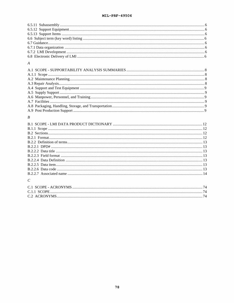
MIL-PRF-49506
78
6.5.11 Subassembly ...................................................................................................................................................... 66.5.12 Support Equipment ............................................................................................................................................ 66.5.13 Support Items .................................................................................................................................................... 66.6 Subject term (key word) listing .............................................................................................................................. 66.7 Guidance.................................................................................................................................................................. 66.7.1 Data organization ................................................................................................................................................. 66.7.2 LMI Development ............................................................................................................................................... 66.8 Electronic Delivery of LMI .................................................................................................................................... 6
A
A.1 SCOPE - SUPPORTABILITY ANALYSIS SUMMARIES ................................................................................. 8A.1.1 Scope .................................................................................................................................................................. 8A.2 Maintenance Planning............................................................................................................................................ 8A.3 Repair Analysis....................................................................................................................................................... 8A.4 Support and Test Equipment ................................................................................................................................. 9A.5 Supply Support ...................................................................................................................................................... 9A.6 Manpower, Personnel, and Training ...................................................................................................................... 9A.7 Facilities ................................................................................................................................................................ 9A.8 Packaging, Handling, Storage, and Transportation................................................................................................ 9A.9 Post Production Support ........................................................................................................................................ 9
B
B.1 SCOPE - LMI DATA PRODUCT DICTIONARY ............................................................................................. 12B.1.1 Scope ................................................................................................................................................................ 12B.2 Sections................................................................................................................................................................ 12B.2.1 Format............................................................................................................................................................... 12B.2.2 Definition of terms............................................................................................................................................ 13B.2.2.1 DPD# ............................................................................................................................................................. 13B.2.2.2 Data title ........................................................................................................................................................ 13B.2.2.3 Field format ................................................................................................................................................... 13B.2.2.4 Data Definition .............................................................................................................................................. 13B.2.2.5 Data item........................................................................................................................................................ 13B.2.2.6 Data code ....................................................................................................................................................... 13B.2.2.7 Associated name ............................................................................................................................................ 14
C
C.1 SCOPE - ACRONYMS ....................................................................................................................................... 74C.1.1 SCOPE.............................................................................................................................................................. 74C.2 ACRONYMS....................................................................................................................................................... 74

STANDARDIZATION DOCUMENT IMPROVEMENT PROPOSAL
INSTRUCTIONS1. The preparing activity must complete blocks 1,2,3, and 8. In block 1, both the document number and revision letter shouldbe given.2. The submitter of this form must complete blocks 4,5,6, and 7.3. The preparing activity must provide a reply within 30 days from receipt of this form.
NOTE: This form may not be used to request copies of documents, nor to request waivers, or clarification of requirements oncurrent contracts. Comments submitted on this form do not constitute or imply authorization to waive any portion of thereferenced document(s) or to amend contractural requirements .
I RECOMMEND A CHANGE 1.DOCUMENT NUMBER 2.DOCUMENT DATE (YYMMDD)
3.DOCUMENT TITLE LOGISTICS MANAGEMENT INFORMATION, MIL-PRF-49506
4.NATURE OF CHANGE(Identify paragraph number and include proposed rewrite, if possible. Attach extrasheets as needed.)
5.REASON FOR RECOMMENDATION
6.SUBMITTER
a. NAME (Last, First, Middle Initial) b. ORGANIZATION
c. ADDRESS (Include Zip Code) d. TELEPHONE (IncludeArea Code)(1)Commercial
(2)AUTOVON(If applicable)
7.DATE SUBMITTED (YYMMDD)
8.PREPARING ACTIVITY
a.NAME USAMC Logistics Support Activity
b.TELEPHONE (Include Area Code)(1)Commercial (2)AUTOVON (205) 955-9837 645-9837
c.ADDRESS (Include Zip Code) ATTN: AMXLS-ALD Redstone Arsenal, AL 35898-7466
IF YOU DO NOT RECEIVE A REPLY WITHIN 45 DAYS, CONTACT: Defense Quality and Standardization Office 5203 Leesburg Pike, Suite 1403, Falls Church, VA 22041-3466 Telephone (703) 756-2340 AUTOVON 289-2340
DD Form 1426, OCT 89 Previous editions are obsolete 198/290 (Unauthorized electronic version)

------------------------------------------------------------------------
CommanderUSAMC Logistics Support ActivityATTN: AMXLS - ALDBldg 5307, Sparkman CircleRedstone Arsenal, AL 35898-7466