performance of three phase induction motor of direct ... · where vsa, v sb and v sc are the ......
TRANSCRIPT
Performance of Three Phase InductionMotor of Direct Torque Control using
Fuzzy Logic Controller
Ranjit Kumar Bindala 1 and Inderpreet Kaur2
1PhD., Scholar Department of Electrical Engineering,Chandigarh University, Ghrauan Mohali, Punjab, India.
[email protected], Department of Electrical Engineering,
Chandigarh University, Ghrauan Mohali, Punjab, Indiainder [email protected]
January 26, 2018
Abstract
Fuzzy logic controller is now days are becoming morepopular in soft computing applications for improving thecontrol technique in induction motor drives. Direct Torquecontrol (DTC) method uses hexagonal path only when ratedvoltage is required at high speed. In this paper three phaseInduction motor model is used with DTC and Fuzzy logiccontroller to control the speed and fluctuations in the torqueof induction motor .The fuzzy logic controller is used to re-duce the flux and torque ripples and improves the perfor-mance of DTC method at very low speed of induction motor.The simulated model is made in Matlab/Simulink softwareto check to the performance of the three phase inductionmotor model.
Key Words : Three phase Induction Motor model,Direct Torque Control, Voltage Source Inverter, Fuzzy logiccontroller.
1
International Journal of Pure and Applied MathematicsVolume 118 No. 19 2018, 159-175ISSN: 1311-8080 (printed version); ISSN: 1314-3395 (on-line version)url: http://www.ijpam.euSpecial Issue ijpam.eu
159
1 Introduction
The three phase squirrel cage induction motors are almost world-wide extensively utilized in industrial applications [1-2]. There aresome difficulties during its torque, flux or speed control of it. Nowa day’s three phase squirrel cage induction motors are becomingmore popular because of economical in cost, rugged construction,and easy to use, reliable and small size [3-4]. The three phase squir-rel cage induction motors are available from few watts to megawattsas per the requirement.
In previous system the speed, torque or flux control of threephase squirrel cage induction motors are very complicated and dif-ficult. In these techniques to control the above mentioned parame-ters the supply voltage is to vary by using auto transformer, supplyfrequency is varied with the help of cyclo converts and numbers ofpoles of the motor [5]. by utilizing these schemes speed , torque andflux control is available but upto certain limits for precise controlthese equipments becomes more costly, to overcome these draw-backs the new direct torque control schemes are proposed [6]. Thedirect torque control scheme was suggested by TAKAHASHI De-penbrock for the speed control of three phase squirrel cage inductionmotor [7-8]. Direct torque control scheme is popular because of thefollowing points [6]:
• Fast dynamic torque response
• Robustness with respect to parameter variations
• Feedback system is not required
• Simple construction and low cost
• No need of external excitation
Despite benefits there are some causes like a highly slower re-sponse during start up and during a step change in torque andstator flux.
2
International Journal of Pure and Applied Mathematics Special Issue
160
2 Material and Method
2.1 Voltage vector model for three phase squir-rel cage voltage source inverter output
The voltage source inverter consists of three phase supply withthree parallel legs each leg consists of two switches which are ableto work as eight possible stator voltage vectors. The torque andflux of three phase induction motor model is controlled by usinghysteresis band within limits [1-2].
V (t) = 23[Va(t) + ZVb(t) + Z2Vc(t)] (1)
WhereZ = ei2/3π (2)
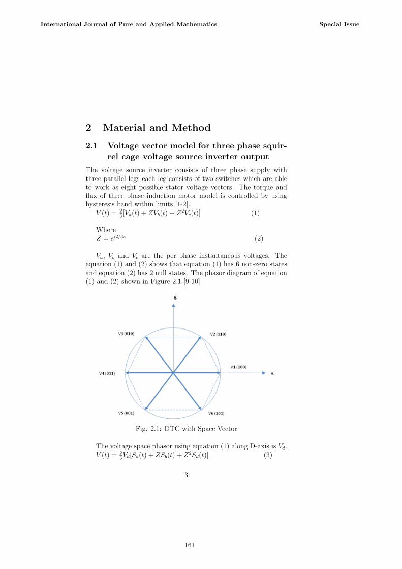
Va, Vb and Vc are the per phase instantaneous voltages. Theequation (1) and (2) shows that equation (1) has 6 non-zero statesand equation (2) has 2 null states. The phasor diagram of equation(1) and (2) shown in Figure 2.1 [9-10].
Fig. 2.1: DTC with Space Vector
The voltage space phasor using equation (1) along D-axis is Vd.V (t) = 2
3Vd[Sa(t) + ZSb(t) + Z2Sd(t)] (3)
3
International Journal of Pure and Applied Mathematics Special Issue
161

2.2 Mathematical model of three phase induc-tion motor model
The mathematical model of three phase induction motor when itis operated in both the states i.e. transient state as well as steadystate [11-13]. The equilateral circuit is used to calculate torque flux,stator voltage, stator and rotor current etc. The stator voltage andstator current and flux equation are [12]:
Stator voltages equations are:Vsa(t) = Rsisa (t) + d
dt(Ψsa(t)) (4)
Vsc(t) = Rsisc (t) + ddt
(Ψsc(t)) (5)
Vsc(t) = Rs isc(t) + ddt
(Ψsc(t)) (6)
Rotor voltages equations are:Vra(t) = Rrira (t) + d
dt(Ψra(t)) (7)
Vrb(t) = Rrirb (t) + ddt
(Ψrb(t)) (8)
Vrc(t) = Rrirc (t) + ddt
(Ψrc(t)) (9)
Converting to dq frame: The three-phase supply voltage is con-verted into two phases by using the given equations. Where Vsa,Vsb and Vsc are the three-phase stator voltages and,Vsd is statorvoltage direct axis and Vsq is stator voltage of quardature axis.isa, isb, iscandira, ira, ircare three phase stator and rotor currents re-spectively, while isd, isq and ird, irq are two phase stator currentsand rotor currents respectively [14].
Flux equations areΨsd = [Vsd − isdRs]
1s
(10)
Ψsq = [Vsq − isqRs]1s
(11)
Ψrd = [ωΨrq − irdRr]1s
(12)
Ψrq = [ωΨrd − irdRr]1s
(13)
4
International Journal of Pure and Applied Mathematics Special Issue
162

Stator current equations areisd = Ψsd
Lr
LX− Ψrd
Lm
LX(14)
isq = ΨsqLr
LX− Ψrq
Lm
LX(15)
Rotor Current Equationsird = Ψrd
Ls
LX− Ψsd
Lm
LX(16)
irq = ΨrqLs
LX− Ψsq
Lm
LX(17)
LX = LsLr − Lm2 (18)
3 Results and Discursion
3.1 Modeling of Three phase induction machine
The three phase induction machine consists of two main parts sta-tor and rotor. Stator is the stationary part and rotor is the rotatingpart. The parameters of three phase induction motors are statorresistance, rotor resistance, stator reactance, rotor reactance, mu-tual and self inductance of the motor [15-16]. The equivalent circuitdiagram with rating is shown in Figure 3.1.
Fig. 3.1: Equivalent circuit diagram of three phase induction motor
3.2 Principle Model of DTC
The DTC scheme consist of Voltage source inverter , six voltagephasors and two zero phasors to keep in sequence order , the stator
5
International Journal of Pure and Applied Mathematics Special Issue
163

flux and torque with in limit of hysteresis band near the commandis shown in figure 2.1. In fig. 1 the DTC space vector the switchingpositions of the voltage source inverter are shown out with similarvoltage vectors based on the model of voltage source inverter shownin figure 3.2 [17,19].In figure 3.2 the upper switches are shown by1,3and 5 and the lower switches are shown by 4,6 and 2.
Fig. 3.2: Switching model of voltage source inverter
The basic block diagram of direct torque control scheme con-sist of supply voltage, voltage source inverter, switching table ,hysteresis controller, flux and torque estimator , input flux , inputtorque and three phase induction motor with feedback arrangementas shown in Figure 3.3[18,20].
6
International Journal of Pure and Applied Mathematics Special Issue
164

Fig. 3.3: Block diagram of conventional DTC scheme
The block diagram of conventional DTC scheme that referencevalue of stator flux and stator torque is compared with actual valuesof three phase induction motor scheme and calculated errors areobtained [21].
3.3 Fuzzy Logic Controller with DTC
Fuzzy logic controller consist of three error input variables such asstator flux, electromagnetic torque and stator flux and one outputknown as voltage space vector. In this Fuzzy logic error is measuredwhich shows the dissimilarity between stator flux with real value ofstator flux. Fuzzy logic errors are measured in terms of negative,zero and positive [22, 26].
Electromagnetic torque error is comparison between actual torqueand desired torque. Electromagnetic torque error is measured interm of gigantic positive, compact positive, gigantic negative, andcompact negative. Flux linkage angle is the between stator fluxwith reference axis [23, 25]. Fuzzy logic controller using with DTCis shown in Figure 3.4[24].
7
International Journal of Pure and Applied Mathematics Special Issue
165

Fig.3.4: Block diagram of fuzzy logic controller with DTC
The DTC using with Fuzzy logic consist of three input variablesi.e. flux , electromagnetic torque and stator flux and one outputknown as voltage space vector. Fuzzy logic errors are measured interms of negative, zero and positive. Electromagnetic torque error isdifference between desired torque and real torque. Electromagnetictorque error is measured in term of large positive, small positiveand large [27, 28].
3.3.1 Working model of Fuzzy logic Controller with DTC
The fuzzy logic model consists of Fuzzy controller, Parks transfor-mation, Inverter, Induction machine model and wind Turbine. Inthis model wind turbine is used as electrical power source to induc-tion motor model, load angle and pitch is used to control the speedof the wind generator [29, 30]. The output of the wind generatoris connected to induction motor machine model through gain. Thespeed and torque of the induction motor model is controlled whenwe compare the reference speed with actual speed. The fuzzy con-troller is used is of mamdani type. It consists of seven membershipfunction. The proposed rules are different from others. To handlethese rules I used NVB and PVS system [31-32].
8
International Journal of Pure and Applied Mathematics Special Issue
166
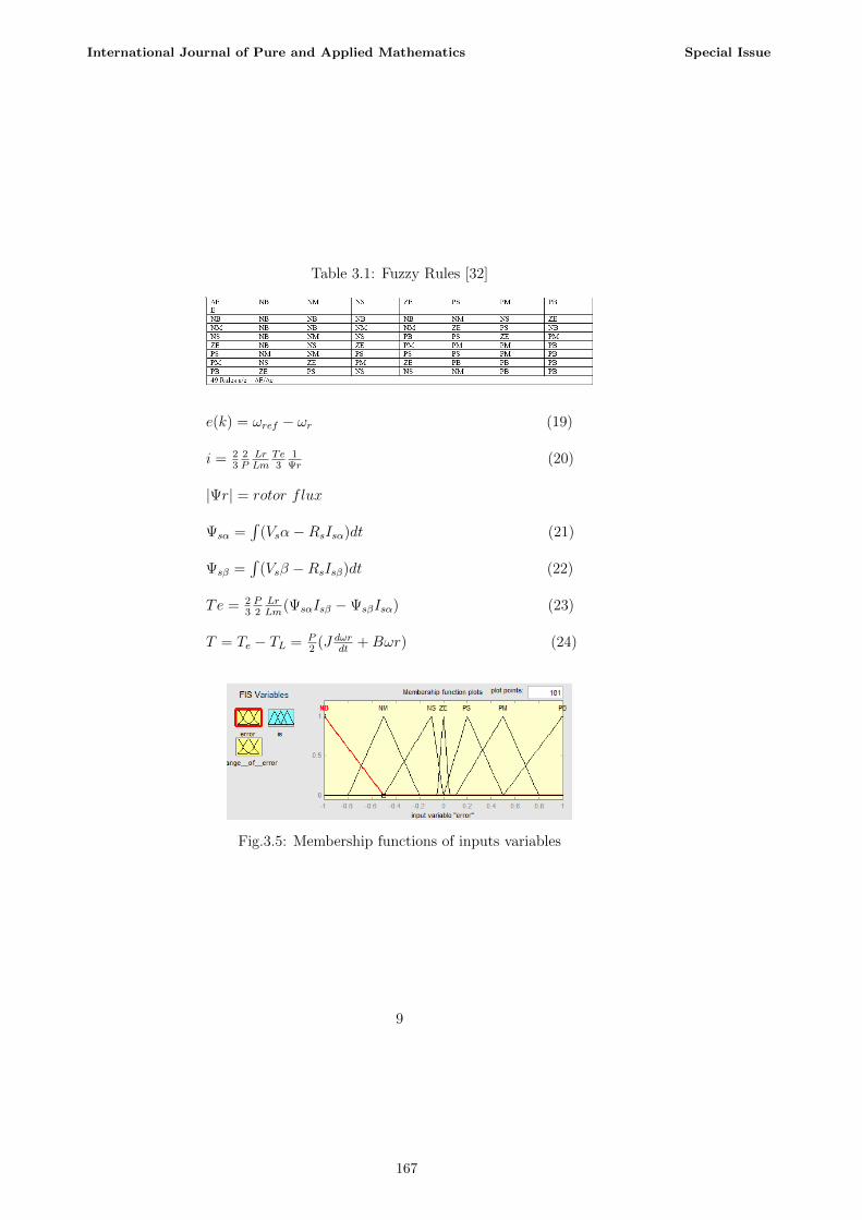
Table 3.1: Fuzzy Rules [32]
e(k) = ωref − ωr (19)
i = 23
2PLrLm
Te3
1Ψr
(20)
|Ψr| = rotor flux
Ψsα =∫
(Vsα−RsIsα)dt (21)
Ψsβ =∫
(Vsβ −RsIsβ)dt (22)
Te = 23P2LrLm
(ΨsαIsβ −ΨsβIsα) (23)
T = Te − TL = P2
(J dωrdt
+Bωr) (24)
Fig.3.5: Membership functions of inputs variables
9
International Journal of Pure and Applied Mathematics Special Issue
167

Fig.3.6: Membership functions of output variables
Fig. 3.7: Simulink model of DTC with Fuzzy Logic controller
As proposed model speed, rise time, settling time, transient timeand torque ripples has been controlled using Fuzzy logic controller.
4 Simulation Analysis
Fig. 4.1: Stator flux trajectory path response DTC with FLC
10
International Journal of Pure and Applied Mathematics Special Issue
168
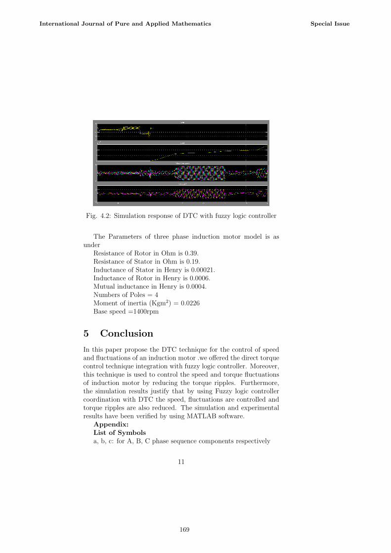
Fig. 4.2: Simulation response of DTC with fuzzy logic controller
The Parameters of three phase induction motor model is asunder
Resistance of Rotor in Ohm is 0.39.Resistance of Stator in Ohm is 0.19.Inductance of Stator in Henry is 0.00021.Inductance of Rotor in Henry is 0.0006.Mutual inductance in Henry is 0.0004.Numbers of Poles = 4Moment of inertia (Kgm2) = 0.0226Base speed =1400rpm
5 Conclusion
In this paper propose the DTC technique for the control of speedand fluctuations of an induction motor .we offered the direct torquecontrol technique integration with fuzzy logic controller. Moreover,this technique is used to control the speed and torque fluctuationsof induction motor by reducing the torque ripples. Furthermore,the simulation results justify that by using Fuzzy logic controllercoordination with DTC the speed, fluctuations are controlled andtorque ripples are also reduced. The simulation and experimentalresults have been verified by using MATLAB software.
Appendix:List of Symbolsa, b, c: for A, B, C phase sequence components respectively
11
International Journal of Pure and Applied Mathematics Special Issue
169

ac: alternating currentd: for direct axis componentsq: for quardature axis componentsem: for electromagnetic (e.g. Tem = electromagnetic torque)Hz: hertzI: current in AmperesJ: moment of inertiaKgm2: kilogram per meter squareL: inductance in HenryLs: leakage inductance of statorLr: leakage inductance of rotorLm: mutual leakage inductanceH: henneryN: speed in rpm0: for zero sequence componentsΨ: flux in WeberP: number of polesq: for quadrature axis componentsr: for rotor quantitiesR: resistance in ohmsRr: rotor resistanceRs: stator resistances: for stator quantitiest: time in secondsT: torque in Newton meterTm: maximum torqueV: voltage in Voltsω: angular speed in radians/secondsX: reactance in ohmsZ: impedance in Ohmsθ: phase angle in radiansψ: phase∆: little changeP: positve functionN: negative functionM: membership functionZ: zero function
12
International Journal of Pure and Applied Mathematics Special Issue
170

References
[1] Tatte Y. N. and Aware M. V. Torque ripple and harmonic cur-rent reduction in three-level inverter fed direct torque controlledfive-phase induction motor IEEE Transition (2017) (In press).
[2] Mohamed. K. Metwaly, Direct Torque and Flux Control ofa Four-Switch Three-Phase Inverter-Fed Synchronous Reluc-tance Motor Drives, Electric Power Components and Systems,Electric Power Components and Systems, pp.1-15, In press.(2017).
[3] Zhang H. and Wang S., Topology Optimization of Rotor Pole inSwitchedReluctance Motor for Minimum Torque Ripple, Elec-tric Power Components and Systems, vol.45, No.8, pp. 905911,(2017).
[4] Taheri A., Harmonic reduction of direct torque control of six-phase induction motor, Procedia Technology, Elsevier ,vol.63,pp.299-314,( 2016).
[5] Barik S. K. and Jaladi K. K., Five phase induction motorDTC-SVM scheme with PI controller and ANN controller,Procedia Technology, Elsevier, vol.25, pp.816-823, (2016).
[6] Bindal R. K. and Kaur I., Comparative Analysis of Differ-ent Controlling Techniques using Direct Torque Control on In-duction Motor, International Conference on Next GenerationComputing Technologies (NGCT-2016) Dehradun, India 14-16,pp.191-196 (2016).
[7] Padmanaban S. K., Wavelet-fuzzy speed indirect field orientedcontroller for three phase ac motor drive-investigation and im-plementation, Engineering Science and Technology an Interna-tional Journal, vol.19, pp.1099-1107, (2016).
[8] Soreshjani M.H., Direct torque controlled space vector mod-ulated method for line start permanent magnet synchronousand induction motors, Transactions of the Institute of Mea-surement and Control, vol.37, no. 6, pp.826-840, (2015).
13
International Journal of Pure and Applied Mathematics Special Issue
171
[9] Saranya M. R. and Satheesh B. H., Low speed estimation insensor less direct torque controlled induction motor drive usingextended kalman filter, International Journal of Power Elec-tronics and Drive System, vol. 6, No. 4, pp. 819-830, (2015).
[10] Pise S. S. and Jape V. M., Direct torque control of inductionmotor using two level inverter, International Journal of Elec-trical, Electronics and Data Communication, vol.3, No.7, pp.19-22, (2015).
[11] Yantour H., Saadi J. and Khoumsi A. , A hybrid system basedapproach to direct torque control of induction motors, Inter-national Organization Scientific Research Journal of Electricaland Electronics Engineering, vol.10, No. 3, pp.60-70, (2015).
[12] Hassan A. A., Direct torque control of an induction motor driveintegrated with sliding mode control and space vector modula-tion, American Association for Science and Technology, vol.2,No.3, pp.159-165, (2015).
[13] Saidas M. G. and Hima T., Steady state direct torque controlof induction motor using by anti-windup PI controller, Inter-national Research Journal of Engineering and Technology, vol.2, No. 4, pp.1336-1340, (2015).
[14] Premalatha D. and Rubini A. S., Direct torque control of brush-less dc motor using PI and fuzzy controller, IJSETR, vol. 4,No. 4, pp.922-926, (2015).
[15] Ouledalia O., Meroufelb A. and Wira P., Direct torque fuzzycontrol of PMSM based on SVM, Procedia Energy Elsevier,vol.74, pp. 1314 1322, (2015).
[16] Jakhar A. and Gaur P. , Comparative study of PI,PID andFuzzy PI controller based direct torque induction motor drive,Advanced Research in Electrical and Electronics Engineering, vol. 2, No. 3,pp.261-265,2015.
[17] Zhao S., Liang J. and Zhao Y., Optimization Design and DirectTorque Control of a Flux Concentrating Axial Flux PermanentMagnet Motor for Direct Driving System, Electric Power Com-ponents and Systems, vol. 42, pp.15171529, (2014).
14
International Journal of Pure and Applied Mathematics Special Issue
172
[18] Joshi B. M. and Chandorkar M. C., Vector Control ofTwo-motor Single-inverter Induction Machine drives, ElectricPower Components and Systems, vol. 42, pp. 11581171, (2014).
[19] M. H. Khan and A. Azam, Hybrid PWM based MRAS speedobserver for sensor-less control of induction motor drive, Inter-national Journal of Latest Research in Science and Technology,vol. 3 No. 3, pp. 52-57, 2014.
[20] Pandian A. and Dhanasekaran R., Performance analysis ofdirect torque control of three phase induction motor, Journalof Theoretical and Applied Information Technology, vol. 62,No. 3, pp.819-824, (2014).
[21] Kumar D., Taker I. and Gupta K., Direct torque control for in-duction motor using intelligent artificial neural network tech-nique, International Journal of Emerging Trends and Technol-ogy in Computer Science, vol. 3, No. 4, pp.44-50, (2014).
[22] Mehra J., Sharma P. and Dubey C. , Comparative analysisof direct torque control and flux control of induction motorusing P and PI controller, International Journal of EmergingTechnology and Advanced Engineering, vol.4, No. 5,pp.887-892, (2014).
[23] Krishna B. V. , Design and comparison of vector and di-rect torque control of 3-phase induction motor drive, Middle-East Journal of Scientific Research, vol. 20, No. 5, pp.586-597,(2014).
[24] Bouzidi B., Basidi B. E. and Masmoudi A., Sensor-less directtorque control method strategy devoted to the control of FSTPIfed induction motor drives, Journal of Electrical Systems, vol.9, No. 3, pp.367-379, (2013).
[25] Patil U. V., Suryawanshi H. M., and Renge M. M., TorqueRipple Minimization in Direct Torque Control Induction MotorDrive Using Space Vector Controlled Diode-clamped Multi-levelInverter, Electric Power Components and Systems, vol. 40,pp.792806, (2012).
15
International Journal of Pure and Applied Mathematics Special Issue
173

[26] Li Y. and Wei H.,Research on controlling strategy of dual bridgematrix converter-direct torque control of induction motor, Pro-cedia Technology, Elsevier, vol. 16, pp. 1650-1658, (2012).
[27] Naas B., Nezil L. et.al, Direct torque control based threelevel inverter-fed double star permanent magnet synchronousmachine, Procedia Technology, Elsevier, vol. 18, pp.521-530,(2012).
[28] Zaky M. S., Ehab M. I., and Khater M. M., Gain SchedulingAdaptive Proportional-integral Controller for a Field-orientedControl of Hybrid Stepper Motor Drives, Electric Power Com-ponents and Systems, vol. 40, pp. 777791, (2012).
[29] Pimkumwong N., Onkrong A. and Sapaklom T.,Modeling andsimulation of direct torque control of induction motor drivesvia constant voltage/hertz technique, Procedia Technology, El-sevier, vol. 31, pp.1211-1216, (2012).
[30] Rashag H. F. and Koh S. P. , Improved close loop stator fluxestimation of direct torque control drive, Procedia Energy, El-sevier, vol. 38, pp.572-577, (2012).
[31] Hajian M., Soltani J. and Markadeh G. R. Arab, Non-linear Direct Torque Control of Sensorless Induction MotorDrives with Parameter Identification and Capable for Very LowSpeeds, Electric Power Components and Systems, vol. 40, pp.16561675, (2012).
[32] Kusagur, Ashok, S. F. Kodad, and BV Sankar Ram. Modellingof induction motor & control of speed using hybrid controllertechnology. Proc. Int. Journal of Theoretical Information &Technology (JATIT), vol.10 No.2, pp. 117-126, (2009).
16
International Journal of Pure and Applied Mathematics Special Issue
174

175

176