performance of oil pumping rings
TRANSCRIPT

DOE/NASA/0256-1NASA CR-175083MTI 86TR17
Performance of Oil Pumping Rings
An Analytical and Experimental Study
(NASA-CR-175063) PERPC6MANCE Of OIL PUMPING N86-31000RINGS: AN ANALY1ICAL AND EXEEEIKEMAL S1DDYiiual Report (Mechanical Technclogy, Inc.)233 p CSCL 20D Unclas
G3/34 43508
M.W. Euseip, J.A. Walowit,O. Pinkus, and P. HolmesMechanical Technology Incorporated
January 1986
Prepared forNATIONAL AERONAUTICS AND SPACE ADMINISTRATIONLewis Research CenterUnder Contract DEN 3-256
forU.S. DEPARTMENT OF ENERGYConservation and Renewable EnergyOffice of Vehicle and Engine R&D
DISCLAIMER
This report was prepared as an account of work sponsored by an agencyof the United States Government. Neither the United States Governmentnor any agency thereof, nor any of their employees, makes any warranty,express or implied, or assumes any legal liability or responsibility for theaccuracy, completeness, or usefulness of any information, apparatus,product, or process disclosed, or represents that its use would notinfringe privately owned rights. Reference herein to any specificcommercial product, process, or service by trade name, trademark,manufacturer, or otherwise, does not necessarily constitute or imply itsendorsement, recommendation, or favoring by the United StatesGovernment or any agency thereof. The views and opinions of authorsexpressed herein do not necessarily state or reflect those of the UnitedStates Government or any agency thereof.
Printed in the United States of America
Available fromNational Technical Information ServiceU.S. Department of Commerce5285 Port Royal RoadSpringfield. VA 22161
NTIS price codes1
Printed copy: A11Microfiche copy: A01
1Codes are used for pricing all publications. The code is determined bythe number of pages in the publication. Information pertaining to thepricing codes can be found in the current issues of the followingpublications, which are generally available in most libraries: EnergyResearch Abstracts (ERA), Government Reports Announcements and Index(GRA and I); Scientific and Technical Abstract Reports (STAR), andpublication, NTIS-PR-360 available from NTIS at the above address.

DOE/NASA/0256-1NASA CR-175083MTI 86TR17
Performance of Oil Pumping Rings
An Analytical and Experimental Study
)
M.W. Eusepi, J.A. Walowit,O. Pinkus, and P. HolmesMechanical Technology IncorporatedLatham, New York 12110
January 1986
Prepared forNational Aeronautics and Space AdministrationLewis Research CenterCleveland, Ohio 44135Under Contract DEN 3-256
forU.S. DEPARTMENT OF ENERGYConservation and Renewable EnergyOffice of Vehicle and Engine R&DWashington, D.C. 20545Under Interagency Agreement DE-AI01-85CE50112

TABLE OF CONTENTS
SECTION PAGE
NOMENCLATURE
SUMMARY
1.0 INTRODUCTION
2.0 ANALYSIS WITH CONSTANT PARAMETERS
2.1 Basic Equations
2.2 Simplified Approach
2.3 The Backstroke
2.3.1 Analytical Approach
2.3.2 Nature of Solution
2.3.3 Performance Characteristics . . . .
3.0 ANALYSIS WITH VARIABLE PARAMETERS
3.1 Thermal Effects ,
3.1.1 The Energy Equation
3.1.2 Lubricant Flow
3.1.3 Modeling of Thermal Problem ....
3.1.4 Calculation Procedure
3.2 Variable Velocity and Squeeze-Film Effects
3.3 Starvation
3.4 Nonparallel Contours ...........
4.0 PARAMETRIC STUDY
3
3
7
9
9
11
15
25
25
25
26
33
35
38
52
5A
58
PRECEDING PAGE BLANK NOT
iii KAN*
TABLE OF CONTENTS (CONT'D)
SECTION PAGE
5.0 EXPERIMENTAL PROGRAM ........ 74
5.1 Tests with Large Babbitt Ring ...... 77
5.2 Tests with the Rulon and Carbon Ring ......... 81
5.3 Tests with the Small Babbitt Ring. 85
6.0 DISCUSSION OF RESULTS 86
6.1 Empirical Correction for Starvation . . 87
6.2 Effects of Viscosity ... ...... 98
6.3 Suggested Design Procedure ..... 98
7.0 CONCLUSIONS ..... 100
8.0 REFERENCES 101
APPENDIX A: PRELIMINARY ANALYSIS OF PUMPING LENINGRADER
SEAL. 102
APPENDIX B: COMPUTER PROGRAM "RING" ........ 116
APPENDIX C: RESULTS OF EXPERIMENTS - NEW SERIES 181
APPENDIX D: FIGURES SHOWING COMPARISON WITH EXPERIMENTAL
DATA AND UNCORRECTED THEORY 203
iv

. NOMENCLATURE
6y U LA Thermal constant, =- , (degree)
pc CP .... •
C Radial clearance • ;
C Clearance at upstream edge when 6^0
d Diameter > .
D Flexural rigidity, Et3/[12(1 - v2)]
E Elastic modulus
F Radial shear force/unit circumferential -length
2 2F Dimensionless shear force FC /(6yU L )' • • - . . o
Hz Hertz
K Dimensionless flow rate, Rj-o
K .... Effective value of K corrected for starvation
L Hydrodynamic land width
L " Effective distance from fixed end to start of film
L. Dimensionless length, L /L
P(x) Radial loading function; see Equation (2-2)
Q Volumetric flow rate
Q Flow for pf = 0
R . Radius of ring
T Temperature
.pc C2(T - T )T Dimensionless Temperature, p
6y U L. o o
U Average rod velocityo
V Normal velocity
c Specific heat
e Length over which .p acts

NOMENCLATURE (CONT'D)
f Frequency
h Film thickness
h Film thickness at x = 0
h Film thickness at x = L
hi Film thickness slope dh«/dx at x = L
h (h/C)
k Integration constant
p Hydrodynamic pressure
p. Sealed Pressure
p. Maximum sealed pressure (Q = 0)
p Clamping pressure
- 2p Dimensionless pressure pC /(6pU L)
2p Dimensionless sealed pressure p,C /(6uU L)
s Stroke
t Ring thickness; time
u Velocity
w Elastic deflection
x Position variable
x Position variable at cavitation point
y Variable across film
t2(R + )Geometric bending parameter, 7
12L*(1 - v2)
6uU L (R + -|)Elastohydrodynamic parameter, =— —
C CtE
Slope of tapered surface, <C - C )/L
Dimensionless loading length, e/L
vi

NOMENCLATURE (CONT'D)
H Dimensionless film height, (y/h)
Vi Viscosity
y Inlet reference viscosity for thermal analysiso
y Viscous heating function, rate of heat generated/unit area
p Density
v Poisson's Ratio
£ Dimensionless position variable x/L
a Squeeze film parameter (4L/S)
\l> Stream function
X Dimensionless starvation factor
SUBSCRIPTS
c Cavitation
F Forward flow
E Elastic
f At x = L
m Maximum
R Back flow; backstroke
1 At leading edge
2 At trailing edge
vii

SUMMARY
A steady-state design computer program has been developed to predict the
performance of pumping rings as functions of geometry, applied loading, speed,
ring modulus, and fluid viscosity. Additional analyses have been developed to
predict transient behavior of the ring and the effects of temperature rises
occurring in the hydrodynamic film between the ring and shaft. The analysis
was initially compared with previous experimental data and then used to design
additional rings for further testing.
Tests were performed with Rulon, carbon-graphite, and babbitt rings. Two
different shaft diameters were used for the babbitt rings. The design analy-
sis was used to size all of the rings and to select the ranges of clearances,
thickness, and loading. Although full quantitative agreement was lacking,
relative agreement existed in that rings that were predicted to perform well
theoretically, generally performed well experimentally. Some causes for
discrepancies between theory and experiment are believed to be due to starva-
tion, leakage past the secondary seal at high pressures, and uncertainties in
the small clearances and local inlet temperatures to the pumping ring.
The design criteria that evolved require the applied loading to be of the
order of the desired pumping pressure, the flow requirements and tolerances to
dictate clearance, and the elastic modulus and ring compliance to be such that
the deflection under load statically results in clamping at very small inter-
ferences so that back flow is inhibited, but that excessive power loss and
wear do not occur.
It was found that the pumping ring could be used to generate its own loading
pressure without any priming if an initial taper was applied to the ring.
However, for untapered rings, an initial loading had to be applied before
self-pumping could be obtained.
A separate preliminary analysis has been performed for a pumping Leningrader
seal. This analysis can be used to predict the film thickness and flow rate
through the seal as a function of pressure, speed, loading, and geometry.

1.0 INTRODUCTION
An analysis of pumping rings was performed under certain simplifying condi-
tions in previous phases of this work [l]. These conditions consisted of
first ignoring the contribution, if any, of the back flow occurring during the
return stroke of the rod." Other simplifications related to the use of
constant or average parameters, namely constant viscosity and mean rod veloci-
ty, throughout the stroke. The latter also presumed the neglect of squeeze
film forces due to the variation of film thickness engendered by the harmonic
motion of the rod.
The comparison ,of experimental data with theoretical results based on the
simplified analysis showed good agreement with respect to maximum pressures
generated by the pumping ring. The flows produced at reservoir pressures
below the maximum, however, were consistently lower in the experiments than
those indicated by the analysis. The agreement between theory and experiment
for the carbon-graphite rings [l] has been found to be incorrect due to an
erroneous use of an excessively low viscosity in the theoretical computation.
The present work, an extension of the previous effort, is aimed at advancing
the analysis of pumping rings. Thermal effects and variable rod velocity were
included and, with it, the effects of squeeze film action in the fluid film.
The analysis was extended to include the backstroke and concurrent cavitation
and their effect on net flow. The new analysis was then used .to run a parame-
tric study in order to obtain optimized configurations of pumping rings of
different shapes and materials including the effects of1 a geometric taper.
The results of tests run on these optimized designs were then compared with
calculations based on the new analysis.
A separate, preliminary analysis of the pumping Leningrader seal has also been
performed. . Since this analysis is separate from the pumping ring work, its
results are presented in Appendix A. .

2.0 ANALYSIS WITH CONSTANT PARAMETERS
2.1 Basic Equations
The equation governing deflection, w, of an axisymmetric shell under bending
is .-•;-•;. • • .
• ... E t3 d4w Eg. w = _p(x) (2.1}
12(l-v ) dx R
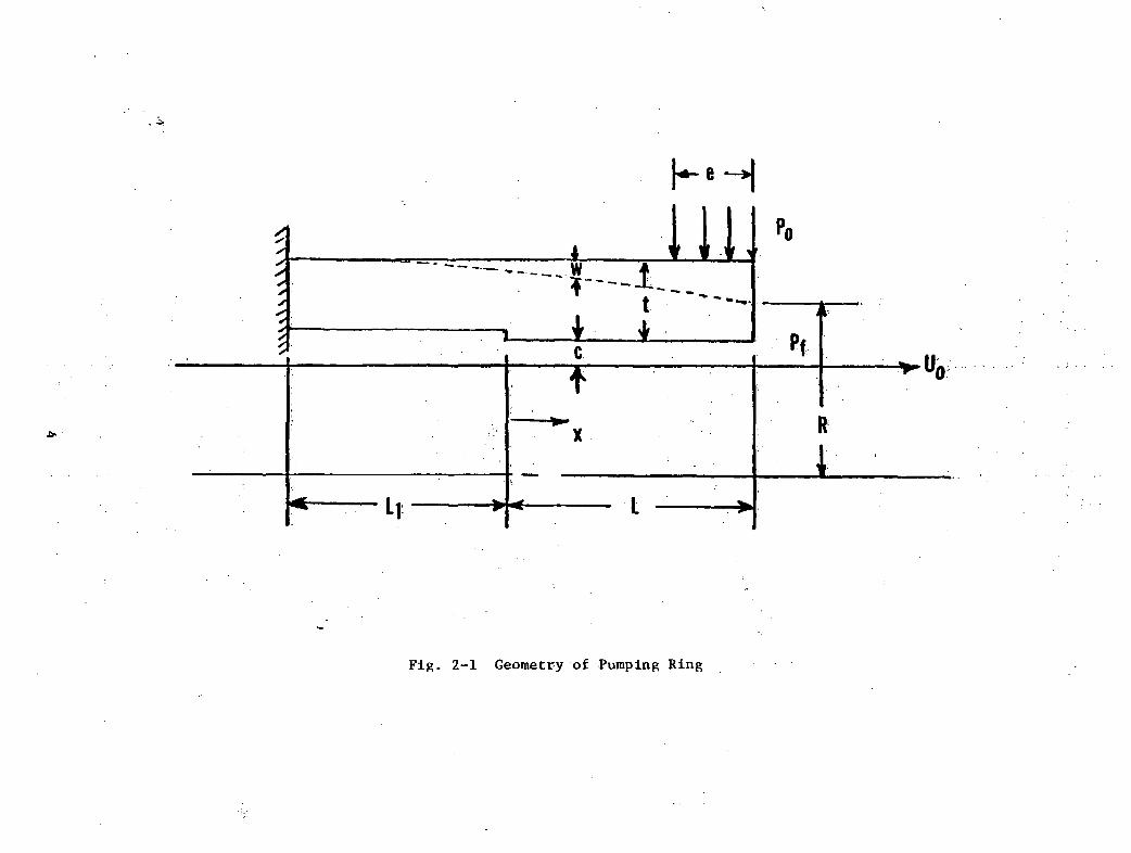
Referring to Figure 2-1, the radially outward loading, P(x), may be expressed in
terms of the clamping load, p , and the hydrodynamic pressure, p, as follows:
f 0, -L1 S x S 0
P(x) = < p , 0 < x S L - e (2-2)
(P-P0» L - e < x S L
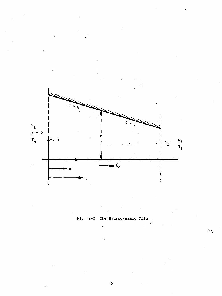
The hydrodynamic pressure, p, is determined from the solution of the Reynolds
Equation
,h-k .( 3 > (2-3)
with the geometry of the hydrodynamic film as given in Figure 2-2. k is a
constant of integration related to the flow, and U do
is related to the frequency, f, and the stroke, s, by:
constant of integration related to the flow, and U is the average speed, which
U = 2fso
11'iThis velocity represents the average of the sinusoidal velocity over each half
cycle. If the system contains two opposing pumping rings, it is double acting
and the average velocity, UQ is assumed to prevail over the entire cycle (though
in two different pumping rings) for the forward stroke, as well as for the back-
stroke. In this manner, the transient problem is reduced to and simplified into
a quasi-steady-state process. For a single ring, the resulting flow should be
divided by 2.
.k
3
occoc•Ha.
P-o0)
pT 1 y. n
i
1
1
' . ' . . 1
— u° !L
Pff
Fig. 2-2 The Hydrodynamic Filin
The film thickness, h, appearing in Equation (2-3) is related to the deflection,
w, by
h = ( C - w ) , 0 < x < L
The system of equations given by Equations (2-1) through (2-3) represents a
fifth-order set of differential equations requiring five boundary conditions,
in addition to a sixth condition for the evaluation of the constant, k, appear-
ing in Equation (2-3). Two conditions result from the clamped-end requirement
w =.-j = 0 at x = -L-dx 1
»
Two conditions resulting from the prescribed pressures at x = 0 and L
p = 0 at x = 0 p = pf at x = L
where p is the sealed pressure. The remaining two conditions relate to the
free-end requiring zero moment and zero shear, or
2 3d w d w _—~ = —r- = 0 at x = Ldx dxJ
The method of solving this set of equations subject to the specified boundary
conditions is outlined in Reference [ 1] . The solution and the results of this
analysis, reported in Reference [1], are based on the constancy of both viscosi-
ty and speed, namely
y = y = constantoU = U = 2fs = constanto
The analysis in Reference [1] did not consider the backstroke and was thus only
applicable to sufficiently high loads and low elastic moduli to result in clamp-
ing during the backstroke.
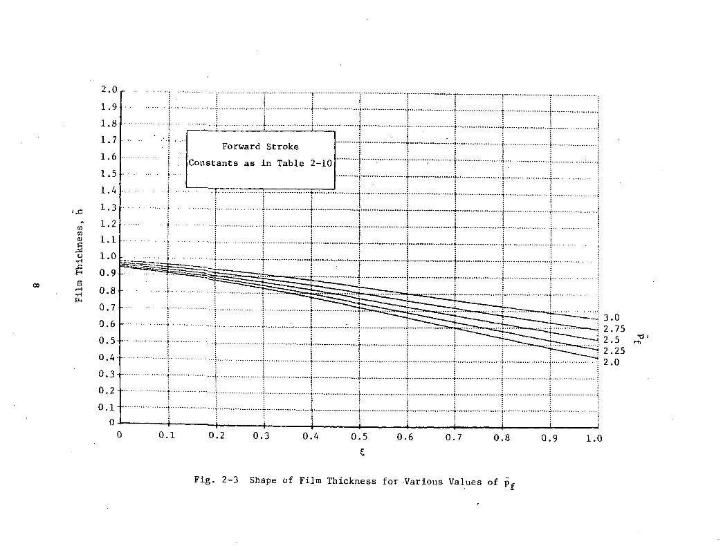
2.2 Simplified Approach
A scrutiny of the pumping ring solutions formulated in Section 2.1 shows that
the shape of the film over the hydrodynamic portion of the ring is nearly
linear for the entire range of ring parameters and operating conditions. A
few such examples are shown in Figure 2-3. Consequently, the problem can be
considerably simplified if one postulates that the configuration of the film
is tapered similar to that of a plane slider. In addition, a constant taper
(shown in Figure 2-2) makes it possible to later treat the backstroke and
accompanying cavitation. Mathematically a constant taper implies that h' =
constant. The pertinent expressions for the hydrodynamic component of pumping
ring action are then given by
h (?)'= h2 + Ah (1 - C) (2'4)
p(h) = l/(h2 - h^ - 1/h + k'/(2h2) + Cx (2-5)
where .
k' = [2h1h2/(h1 +h2)j[l - (h1h2pf)]
(h2 pf)l
The elastic deformation equation remains the same and may be written in dimen-
sionless form as
o (d4h/d£4) + h =
1 for -L < £ < 0
1 + pp for 0 < £ < 1 - e • (2-6)
1 + 3(p - p ) for 1 - t < £ < 1o
The solution algorithm thus consists of determining values for h2 and Ah by
the use of the secant method. Equation (2-6) is solved subject to the
previously stated elasticity boundary conditions. Convergence is achieved
COOJ3'
CO3O•HCOCOCDcHft!
0)O.
oo•H
q '

when the values of ii(l) and h'(l) computed from the solution to Equation (2-6)
are within the prescribed tolerance limit of the values of h*2 and -An used in
calculating p from Equations (2-4) and (2-5).
2.3 The Backstroke
2.3.1 Analytical Approach
The previous analysis assumed clamping during the backstroke. This is valid
for very high loadings, or for highly flexible pumping rings. Lower ring
loadings which do not cause clamping during the entire backstroke may be
desirable for pumping ring design in order to reduce wear. Also, when the
upstream pressure is high, the ring may stay open during the reverse stroke,
even under high clamping forces. Thus, backstroke effects are here added on
to the analytical model.
The basic equations remain unchanged except for two important aspects. One is
that the shaft motion will be in the negative x direction; thus Reynolds
Equation assumes the form
= -[(h - K)/h3] (2-7)
The other critical modification consists in the appearance of cavitation. As
shown in Figure 2-4, due to the divergence of the film in the direction of
motion, there may not be enough fluid to fill the gap at sufficiently high
values of h. The fluid film will then break up into a pattern of streamers
similar to that which occurs in the diverging films of a journal bearing.
From continuity requirements, the downstream boundary conditions of C , where
the film ends, must then satisfy the following boundary conditions:
(dp/d£) at 5 = C =0
(2-8)
P(5C) =0

CavitationRegion
Fluid ;Film .
Fig. 2-4 Pumping Ring During Reverse Stroke
10

To account for cavitation during the backstroke, the equations are integrated
backward from £ = 1. As for the forward stroke solution, values of 62 and Ah
must be determined by using the secant method. Selected values for 62 and Ah
are used in determining h(£) from Equation (2-4) which is in turn substituted
in the Reynolds Equation (2-7). The resulting equation is then integrated
analytically, subject to the constraints that p(l) = p_ , and either the condi-
tion given by Equation (2-8) for 0 < £ < 1 or the condition p(0) = ;0 if cavi-
tation is not predicted to occur. These conditions are sufficient to
determine the constant, K, £ (if applicable), and the pressure distribution,
p(£). Equation (2-6) may now be integrated backward from £ = 1, with the
boundary condition at 5 3 1 such that
h(l) = h2h'(l) = -Ah
h"(l) = h'"(l) = 0
The secant method is then used to find the values of h£ and Ah that make the
quantities |h(-Li) - 1| and |h'(-Li)| be within prescribed tolerance limits.
The solutions so obtained provide dimensionless values of the film thickness
profile, the pressure profiles and the flow rates for prescribed values of
parameters a, 8, p. , p,, £, and LI-
2.3.2 Nature of Solution
The nature of the solution for the backstroke depends very much on the value
of pf relative to the clamping force, p . It is thus first necessary to
describe the conditions which are apt to generate either high or low levels of
Pf .
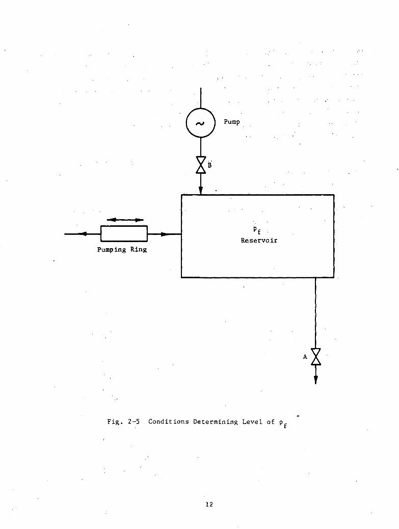
If a pumping ring delivers oil to a closed reservoir of finite volume, the
parameters <X, 8^ £, and p describing the pumping ring will predetermine theo •
maximum p that the pumping ring is likely to generate. At that point, i.e.,
when p is reached, there will be no further inflow into the reservoir, andfm
the pressure in the reservoir will be maintained by pumping ring action at
p . In Figure 2-5 this situation would be represented by both valves A and Bfmbeing closed. However, should there be an outflow from the reservoir, that
11
Pump
Pumping RingReservoir
Fig. 2-5 Conditions Determining Level of p
12

is, were valve A open, then the pumping ring would be delivering a net inflow
equal to the amount of outflow, with the pressure in the reservoir below the
maximum, i.e., pf < pf • On the other hand, if an external pump were to deliv-
er a certain flow, then it is possible to have pf > pf . The pumping ring
would then be overloaded. The net flow over a cycle would be negative and the
outflow through the pumping ring would equal the inflow delivered by the pump.
Since there is no external pump .in the present system, the overloaded condi-
tion will be of academic interest only.
The interaction of pumping ring behavior versus conditions in the reservoir
has a direct bearing on the nature of the backstroke solution. The mechanism
can be summarized as follows:
• If p is low, i.e., if there is an appreciable outflow from the reser-
voir, the film, during the backstroke always cavitates. It is only by
having a cavitating backstroke that a net inflow can be maintained over
a complete cycle.
• At high values of p , there are generally two possible solutions, name-
ly:
- High h.2 with a noncavitating film
- Low h2 with a cavitating film
V:'
Such a double set of possible solutions is shown in Figure 2-6, both
the same pj = 2.7 and po = 3.5. The performance of the pumping ring
under these two sets of conditions is as follows:
Noncavitating Cavitating
Back h2 0.482 0.120
Forward h2 , 0.580 0.580
Back K -1.433 -0.225
Forward K -0.42 -0.42
Net K -1.85 -0.642
13

CO0)3i—I
COooencooCOcuotuen0)HI
.H43
•HCOCOoCM00
•Hft,
O
• If there is no supply of oil to the reservoir by a pump, that is, if the
pressure, p., is generated by the pumping ring only, then the solution
of a high h2 with a npncavitating film is practically impossible, since
a thick noncavitating film would produce a net outflow so that no high
p producing that outflow could possibly be generated in the first
place.
Thus, in conclusion, for practical cases of an active pumping ring, the back-
stroke is always accompanied by cavitation.
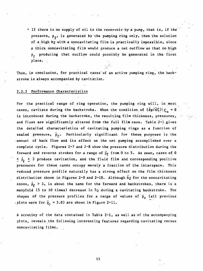
2.3.3 Performance Characteristics
For the practical range of ring operation, the pumping ring will, in most
cases, cavitate during the backstroke. When the condition.of (dp/d£)|£ = 0
is introduced during the backstroke, the resulting film thickness, pressures,
and flows are significantly altered from the full film case. Table 2-1 gives
the detailed characteristics of cavitating pumping rings as a function of
sealed pressure, pf. Particularly significant for these purposes is the
•amount of back flow and its effect on the net pumping accomplished over a
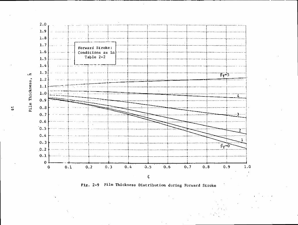
complete cycle. Figures 2-7 and 2-8 show the pressure distribution during the
forward and reverse strokes for a range of pif from 0 to 5. As seen, cases of 0
< p < 3 produce cavitation, and the fluid film and corresponding positive
pressures for these cases occupy merely a fraction of the interspace. This
reduced pressure profile naturally has a strong effect on the film thickness
distribution shown in Figures 2-9 and 2-10. Although h£ for the noncavitating
cases, pf > 3, is about the same for the forward and backstrokes, there is a
manyfold (5 to 10 times) decrease in h2 during a cavitating backstroke. The
shapes of the pressure profiles for a range of values of po (all previous."r-*
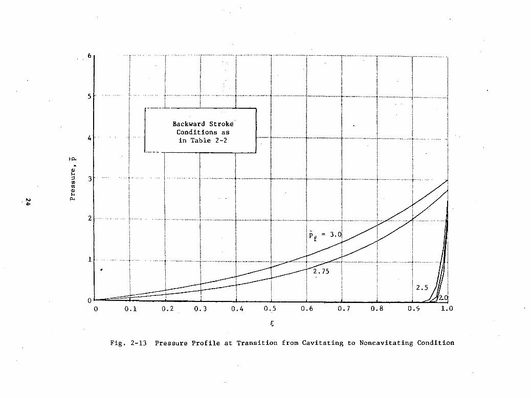
•plots were for p = 3.0) are shown in Figure 2-11.
A scrutiny of the data contained in Table 2-1, as well as of the accompanying
plots, reveals the following interesting features regarding cavitating versus
noncavitating films.
15
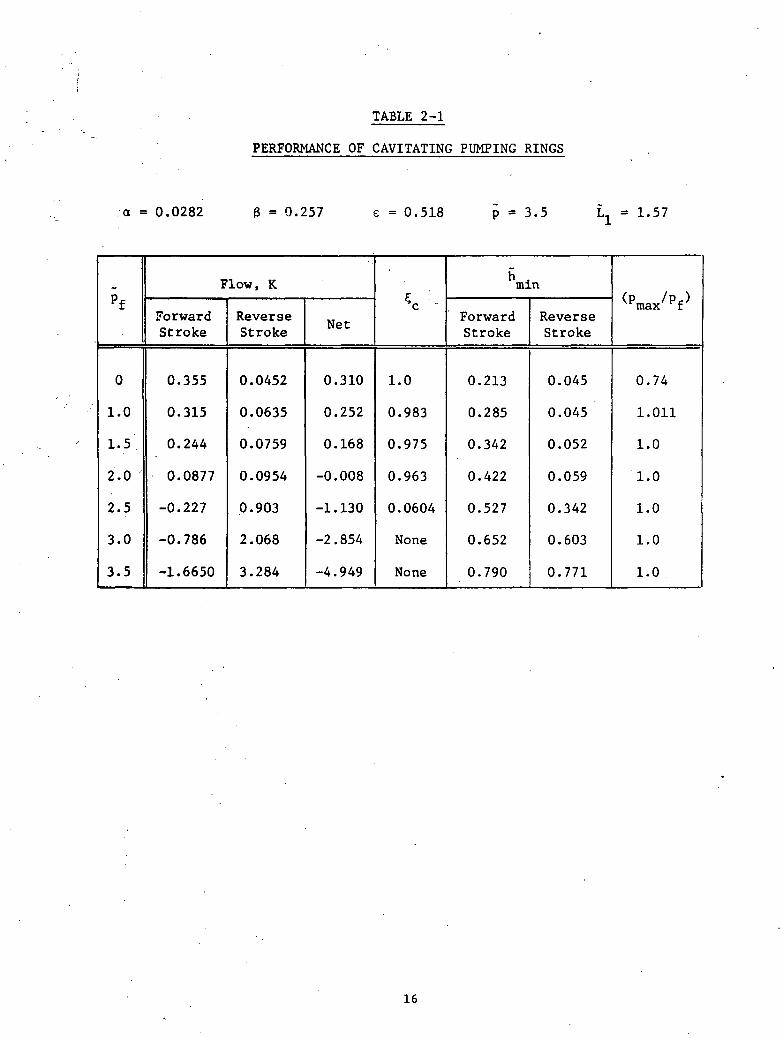
TABLE 2-1
PERFORMANCE OF CAVITATING PUMPING RINGS
a = 0.0282 B = 0.257 e = 0.518 3.5 1.57
pf
0
1.0
1.5
2.0
2.5
3.0
3.5
Flow, K
ForwardStroke
0.355
0.315
0.244
0.0877
-0.227
-0.786
-1.6650
ReverseStroke
0.0452
0.0635
0.0759
0.0954
0.903
2.068
3.284
Net
0.310
0.252
0.168
-0.008
-1.130
-2.854
-4.949
V-
1.0
0.983
0.975
0.963
0.0604
None
None
min
ForwardStroke
0.213
0.285
0.342
0.422
0.527
0.652
0.790
ReverseStroke
0.045
0.045
0.052
0.059
0.342
0.603
0.771
<Pmax/Pf)
0.74
1.011
1.0
1.0
1.0
1.0
1.0
16

I00c•HP0coCO•HP01l-i3COU)OJ1-100•H
u-iC
M
d 'a
an
ssa
aj17

01o0)to1-1<u>nPS00cQO•HU3CO•HQCO(001l-l
03ICSI
00•rl
18
<uJ*o1-4
3•OO•HU343•H»-l4Jw•HQCOCOcuo•HHerH•Hboc•H
19

oh4JCOa)(H
i
•H>-i3"Oco43•H)-i4JCO•HOCOCO0)u•Hsi-i•r(•P
*ICMoc•H
20

POOR
oM4J0)CflV0)
I1-1ooMP-.3COcocuiCM60
•H
oosr
f) rsj
r-i o
oo
21

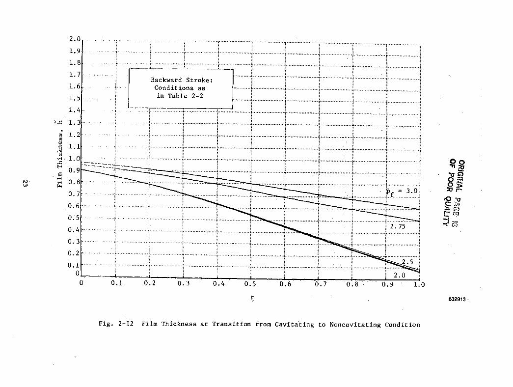
• The change from a cavitating to a noncavitating film is rapid. This is
shown in Figures 2-12 and 2-13 where the transition region
(2.0 < pj < 3.0) is plotted in some detail. The onset of cavitation
seems to occur at about pf = 2.5 where £ - 0.
• Noncavitating films seem to be accompanied by a net reverse flow even
during the forward stroke, emphasizing the previous remark, that such
cases would be of little practical interest in the application of pump-
ing rings.
• The total net flow, including both the forward and backstrokes, becomes
negative, even for cavitating films at about p"f - 2.0.
22
ORIGINA
°F
eo-ac8c•HCOucoZacceootocCO03CO0)
HCN
i-HCN60
•H
23
co•HCO60edocoo4-1
ecc•H4-1tflcoueoco•HCflCCOcO010)COQJVJeuiCM60
•H

3.0 ANALYSIS WITH VARIABLE PARAMETERS
This part of the analysis not only abandons the assumptions of constant speed
and constant viscosity but also considers some other factors which were previ-
ously neglected. Specifically, the analysis included the following elements:
• Thermal effects
• Variable speed
• Squeeze film action
• Starvation
• Nonpara1lei contours.
Of course, the analysis also retained the backstroke and accompanying
cavitation. However, since for the cavitating backstroke, the film thickness is
of limited extent, the refinements of variable temperature were not included for
that part of the cycle. Thermal effects and transient effects were considered
separately to obtain their individual influence. This provides the quantitative
corrections associated with these effects without adding the high degree of
complexity of a fully coupled analysis.
3.1 Thermal Effects
3.1.1 The Energy Equation
Since no side leakage exists, the one-dimensional energy equation could be used.
This, of course, assumes that temperature variation with y can be averaged, a
fact which, as will be seen later, is particularly relevant here. It was also
assumed that all the heat generated is convected away by the lubricant.
Ignoring conduction, the one-dimensional energy equation can be written as,
pcu(3T/3x) = y[Ou/3y)2] (3-1)
Since, from one-dimensional bearing theory
(3'2)
25
Equation (3-1) can be integrated with respect to y in the interval 0 < y h to
yield
PCh *\ * T
dp. ,di.
~2 T2y ~3x' ^3x; 12y h (3-3)
or
pc12yU ho
,2-,
1. a_h _ 3p12u "3x"
Normalizing and utilizing the relationship
(1/V) Op/35) = (h - K)/(h J)
(3-4)
the following can be obtained
3T/3? {[(h - K) 2 / (h 3 ) ] (3-5)
where
U L(T - T )o o o
pc(C2)
3.1.2 Lubricant Flow
The flow pattern at the interface of a pumping ring was somewhat problematic.
The nature of this flow can' be visualized in Figure .3-1. As shown in Figure
3-la, at zero or low upstream pressure, the flow is mainly forward, with only a
small pocket of fluid circulating near the inlet of the film. This recirculat-
ing flow is induced by the adverse hydrodynamic pressure gradient prevailing
near x = 0. When the level of pf rises, more and more of the forward flow near
26

W////M Recirculating Flow
b) Moderate p
u <
c) High p.
d) Very High p.
Fig. 3-1 Lubricant Flow in the Fluid Film
27
the stationary surface is blocked and eventually reversed (Figure 3-lc) by the
static pressure gradient induced by pf. Eventually, when the upstream pressure
is sufficiently high, fluid from the sealed chamber begins to leak backwards
along the stationary surface. When the magnitude of pf becomes very high (Fig-
ure 3-Id), most of the flow is backward, with only thin, vanishing layers of
forward and recirculating flows maintained near the moving surface.
Thus, in general, there are three layers of flow possessing the following char-
acteristics:
• Forward Flow - This flow is along the moving surface. It enters at a
temperature, T , that prevails at x = 0 and is heated on its way to the
reservoir to some T at x = L.max
• Recirculating Flow - This flow also enters at a temperature, T , but
various portions of that flow penetrate only part way into the film
before they are reversed and returned to their source. It should be
noted that the bulk of the flow recirculates near the entrance, where h
is large. It undergoes relatively little viscous shearing, resulting in
low energy dissipation to the fluid.
• Reverse Flow - This flow originates in the reservoir entering at a
temperature, T,., and is heated while traveling upstream. Its maximum
temperature is reached at the entrance to the pumping ring, at x = 0.
In view of these characteristics, only fluid which transverses the whole length,
L, i.e., only the forward and reverse flows, was considered instrumental in
carrying away the dissipated heat. Since the bulk of the intermediate layer
recirculates near the entrance where the temperature differential is relatively
small, its effect is left out of the heat balance. This treatment represents a
conservative approach because inclusion of the recirculating flow would yield
lower temperatures and thus safer operating conditions than those predicted by
the present method.
28
The first task was to find expressions for the three flow regimes in terms of
ring geometry and its operating conditions. Defining a dimensionless transverse
coordinate and a dimensionless velocity by
u(y) = (u/uo); n(O = [y/h]
the velocity from Equation (3-2) may be expressed in dimensionless form as
u= 3(1 - K/h) T)0l - 1) + (1 - TO . (3-6)
The line of zero velocity, or the line below which all fluid flows forward and
above which the flow is backward, is easily obtained from Equation (3-6) by
writing u = 0 which yields the locus
u-0 3[l-K/h(Ol
At a given £, the total flow contained between the moving surface and any point
(TI, £) line is given by
*Oi,O = h o;n u(n') dn-'
and after integration yields
*Ol,O = ftnOl - I)2 + Kn2 (3/2 - n) (3-8)
By assigning to <KT|,5) various constant values, the flow streamlines are
obtained. The net flow, of course, is contained between TI = 0 and T) = 1 or
=qNET
which is shear flow at h = K where (dp/d£) = 0.
The film thickness is given by
h2[l + (a -
29
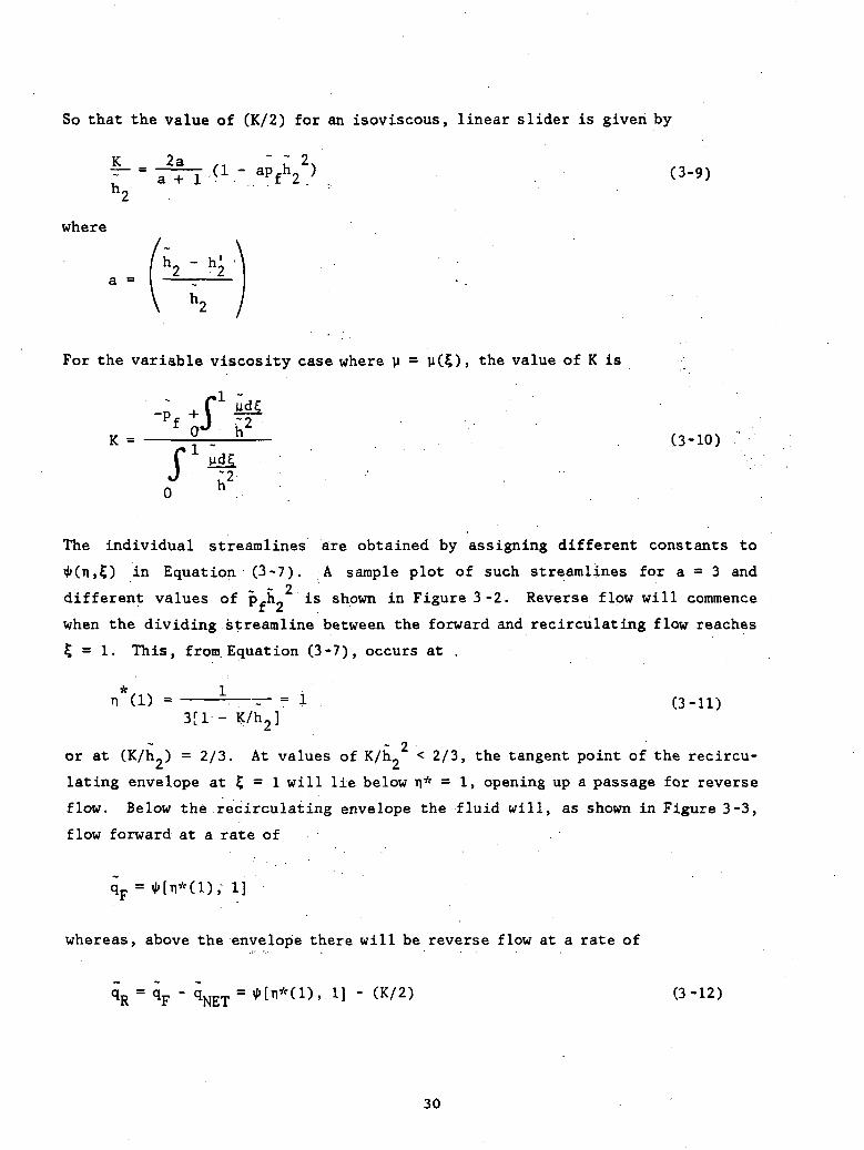
So that the value of (K/2) for an isoviscous, linear slider is given by
K 2a . ~ ~ 2.
where
For the variable viscosity case where y = v(£)> the value of K is
K -- , - . (3-10)
;z .h
fJ
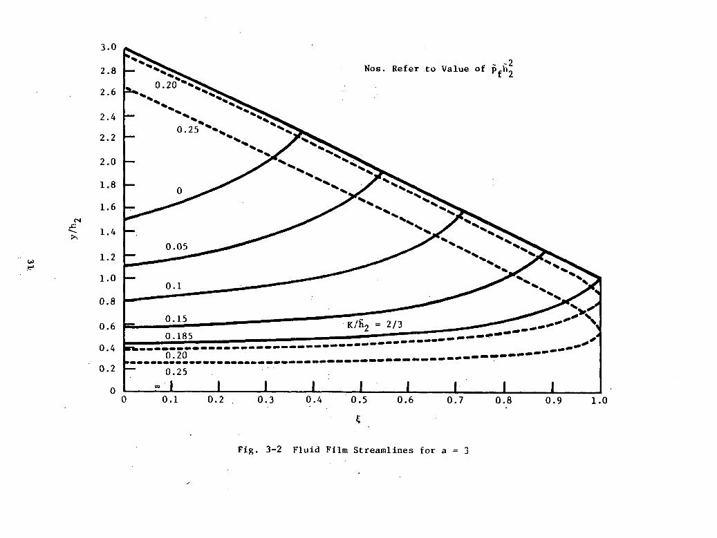
The individual streamlines are obtained by assigning different constants to
5) in Equation (3-7). A sample plot of such streamlines for a = 3 and~ 2different values of Pfh_ is shown in Figure 3 -2. Reverse flow will commence
when the dividing streamline between the forward and recirculating flow reaches
5 =• 1. This, from. Equation (3-7), occurs at .
n (1) - - — — = 1 (3-11)3[1 - K/h2]
~ 2or at (K/h.) = 2/3. At values of K/h. < 2/3, the tangent point of the recircu-
lating envelope at 5 = 1 will lie below TI* = 1, opening up a passage for reverse
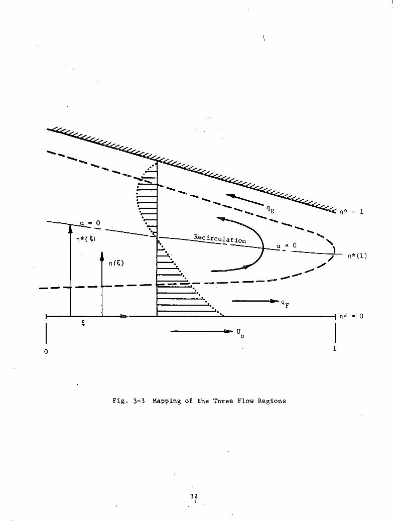
flow. Below the recirculating envelope the fluid will, as shown in Figure 3-3,
flow forward at a rate of
whereas, above the envelope there will be reverse flow at a rate of
1] - (K/2) (3-12)
30
'O.
<uH-l
<uOS
m
cr\
O00
O
OU-J
COcucBfl0)l-l4-1(/I
•a•H3CMI8C
•HCb
CM
O
aovo
vr•C
N
tvi•tN
o•
tM
oovo
VO
<!•
CM
O
O
O
O
31\
n* = l
= 0
Fig. 3-3 Mapping of the Three Flow Regions
32
3.1.3 Modeling of Thermal Problem
•
As stated previously, the viscous heating is assumed to be convected away only
by the fluid that passes the interspace, be it to the right or to the left. For
this purpose, the interspace is modeled so as to be filled with these two
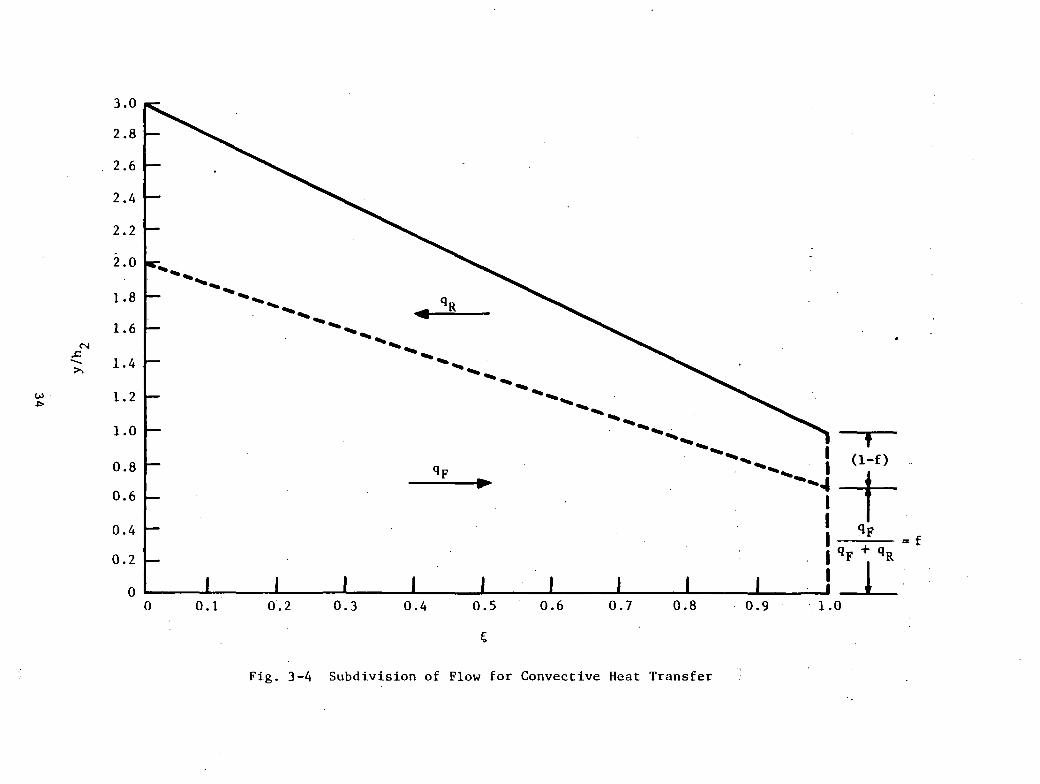
streams, i.e. a forward flow, q,,, and a reverse flow, qD, as shown in Figure 3-4.r KBy designating
f = qF/(qF + qR) (3-13)
f6(x) will be the heat convected to the right by q^ and (1-f) 8 the heat
connected to the left by qD. Likewise, temperatures will be averaged across theK
film (i.e., in the y but not in the x direction) with T x) and TD(x) represent-r K
ing the temperature profiles generated in the two flow layers, q_ and q . Ther K
overall average temperature profile will be obtained from
T(x) = f Tp(x) + (1 - f) TR(x) (3-14)
The viscosity at each x station will be based on this averaged temperature, i.e.
u(x) = u[T(x)].
The expression for the viscous heating (Section 3.1.1) is exact in the sense
that the losses are calculated over the exact velocity profile, including the
region of recirculating flow, namely-
0(x) = y(x) Q/h (du/dy)2dy (3-15)
where u (x,y) is the velocity profile shown in Figure 3-3. Consistent with the
flow model, u(x) in the calculation of this viscous shear will be that corre-
sponding to the average temperature T(x).
It should be noted that, whereas with no reverse flow (qD = 0), the temperatureKat the inlet to the film is a constant equal to T , this is no longer true when
reverse flow sets in. The reverse flow, starting at an initial temperature, T,,
33
ooor-OvO•
OmoenoCN
O
<Uu-iencCOMHCO013Cy01CouoCo•HCO•H•HT
3£>3onoo
I I
I I
I I
I I
I I
I I
Ioo
vO
CN
oooo
-3- C
N
0
O

will reach a maximum at x = 0 and, since temperatures are averaged across y, the
inlet temperature will be some T ' > T .o o
3.1.4 Calculation Procedure
The procedure to be followed in calculating thermal effects in the fluid film
is, in view of the previous discussion, as follows:
a. The differential equation to be solved is
h - K
where due to the variable viscosity
K0 h
f MilJ , 30 h
and
[ 6u U L . "1r + —^-^ T (£)° PC C2 J
b. If (K/h_) > 2/3, there is no reverse flow and
3hl(3-16)
with T = T at ? = 0.o
35

c. If (K/h.) < 2/3, there is reverse flow, and the following quantities
have to be established in order to account for both the forward and
backward streams:
1-4
+ 2K(n*) [3/2 - i*] = 2qp
KR = - K =
= Kp + = 2KF - K = 2(qF + qR) =
dT (h - K)* , 1
h3 3h
(3-17)
Equation (3-17) needs a solution with two different boundary conditions:
• For TF «), T = TQ at $ = 0
• For T , T = Tf at $ = 1
The averaged temperature, any given £> is thus
T(OTRKF
where
T =pc C (T - T )o
6M U Lo o
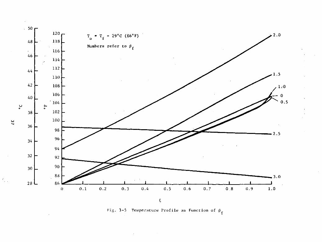
A sample solution for the temperature profile in the fluid film for various
values of upstream pressure is given in Figure 3~5. The solutions are for the
case of equal upstream and downstream boundary temperatures. Curves which start
at T = 86°F are those without reverse flow and thus have what may be called a
conventional profile. However, at pf > 1.5, there is reverse flow and, due to
the averaging of temperatures across y, the inlet temperature is higher than
36
to.ovOG
OHII
I I
oCN
J
I
00
oino
'0.
CCc/l150)u01Q
.
mi
CN
O
ooooo
o
oC
MO
oCC
Obo
oo
Oinoo
sO*
CM
<r -a-
ooo
\o<r
CMCO
COc
COCM
37

86°F. It is interesting to note that, due to the cooling effect of the backward
flow, the maximum temperatures in the film actually decrease as the back flow
increases above a certain level. Thus;,...for p.. = 0, > Tu . = ,10,7°F,. and for• • '; • ' rf ' , max 'p = 3.0, T = 92°F and occurs not at the trailing but "at the leading edge ofi nicLxthe film. The highest temperatures, occur at some intermediate combination of
forward and backward flows; in this particular example..it happens at p = 2.0
with! reaching 120°F.IDcLX . • '
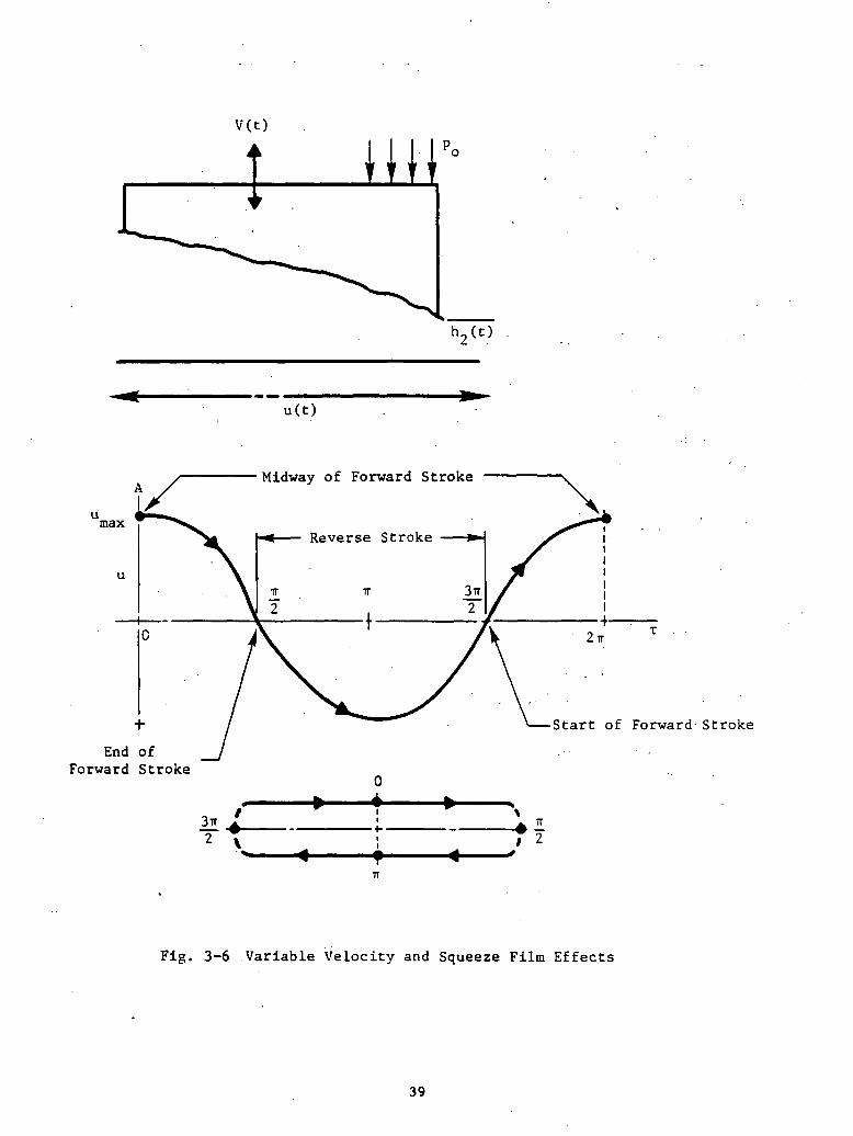
3.2 Variable Velocity and Squeeze-Film Effects
Throughout the previous discussions,, the rod .velocity .was considered .to be
constant, given by U = 2sf. This, of course, represents the average velocity
over each half cycle. In actuality, the rod, driving a crankshaft, moves with a
variable velocity given by
u = u cosir2ftmax
where
u = fs = TtU /2 • -max o
Consequently, a normal velocity component and squeeze film forces are imposed on
the ring, as shown in Figure 3-6. These are generated by a variation of the
hydrodynamic forces and of film thickness, as a function of the variable veloci-
ty. The normal velocity introduces perturbations on nearly all the relevant
quantities, such as film thickness, pressures, flows, extent of cavitation, and
others. •• • ••' ••- •' * • '•'" •• ' - '
When variable velocity and squeeze-film-"-effects.vare included, the Reynolds
Equation becomes:
[h3(3p/35)l = .(ir/2)[cosT(3h/3O +-a(3h/.3f)] ' ' (3-19)
38
V(t)
u(t)
umax
End ofForward Stroke
Midway of Forward Stroke
Start of Forward Stroke
/-*-
Fig. 3-6 Variable Velocity and Squeeze Film Effects
39
where o is the squeeze-film parameter given by 0 = 4L/s, and t is the dimension-
less time T = 2irft.
The relevant boundary conditions are:
• For no caviation: p(0)=0;p(l)=p
• For cavitation: p(l) = Pf»dpd£
= 0
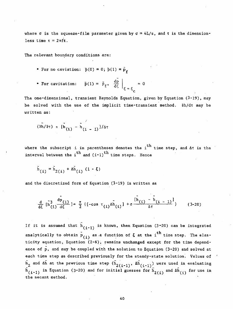
The one-dimensional, transient Reynolds Equation, given by Equation (3-19), may
be solved with the use of the implicit time-transient method. 3h/di may be
written as:
- h(± _
where the subscript i in parentheses denotes the i time step, and AT is the
interval between the i and (i-1) time steps. Hence
and the discretized form of Equation (3-19) is written as
0-20,
If it is assumed that h,._ . is known, then Equation (3-20) can be integrated
analytically to obtain P,.^ as.a function of £ at the i time step. The elas-
ticity equation, Equation (2-6), remains unchanged except for the time depend-
ence of p, and may be coupled with the solution to Equation (3-20) and solved at
each time step as described previously for the steady-state solution. Values of
hL and Ah at the previous time step C^of-lV f-11^ were used in evaluating
h,.,. in Equation (3~20) and for initial guesses for h9,., and Ah,., for use in
the secant method.
40
Quasi-static solutions (o = 0) were obtained at the middle of the forward stroke
(T.= 0) to start the marching procedure. Solutions were then computed at
successive time steps until periodic solutions were obtained.
Sample solutions were run on a pumping ring having the following dimensionless
characteristics:
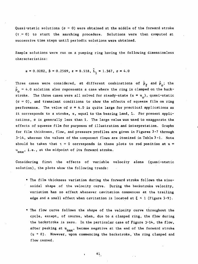
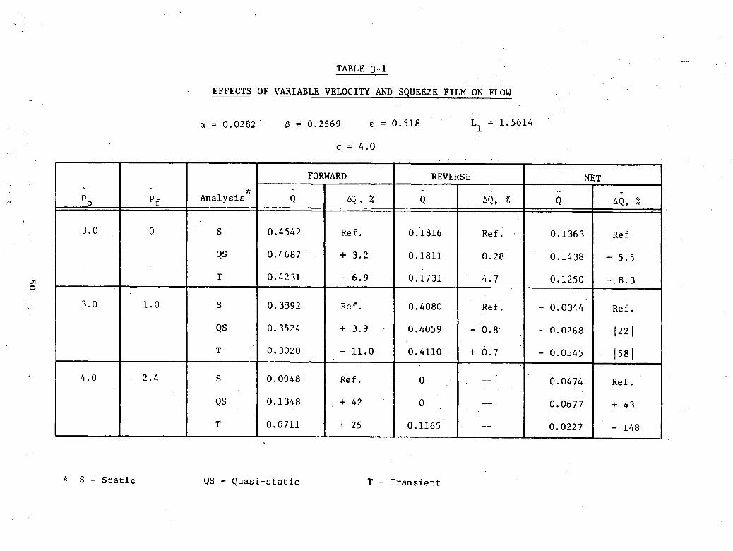
a = 0.0282, 3 = 0.2569, e = 0.518, L = 1.567, a = 4.0
Three cases were considered, at different combinations of p. and p ; the
p =4.0 solution also represents a case where the ring is clamped on the back-
stroke. The three cases were all solved for steady-state (u = u ), quasi-static
(o = 0), and transient conditions to show the effects of squeeze film on ring
performance. The value of o = 4.0 is quite large for practical applications as
it corresponds to a stroke, s, equal to the bearing land, L. For present appli-
cations, o is generally less than 1. The large value was used to exaggerate the
effects of squeeze film for purposes of illustration and interpretation. Graphs
for film thickness, flow, and pressure profiles are given in Figures 3-7 through
3-14, whereas the values of the component flows are itemized in Table 3-1. Note
should be taken that T = 0 corresponds in these plots to rod position at u =
u , i.e., at the midpoint of its forward stroke,max' ^
Considering first the effects of variable velocity alone (quasi-static
solution), the plots show the following trends:
• The film thickness variation during the forward stroke follows the sinu-
soidal shape of the velocity curve. During the backstroke velocity,
variation has no effect whenever cavitation commences at the trailing
edge and a small effect when cavitation is located at 5 < 1 (Figure 3-9).
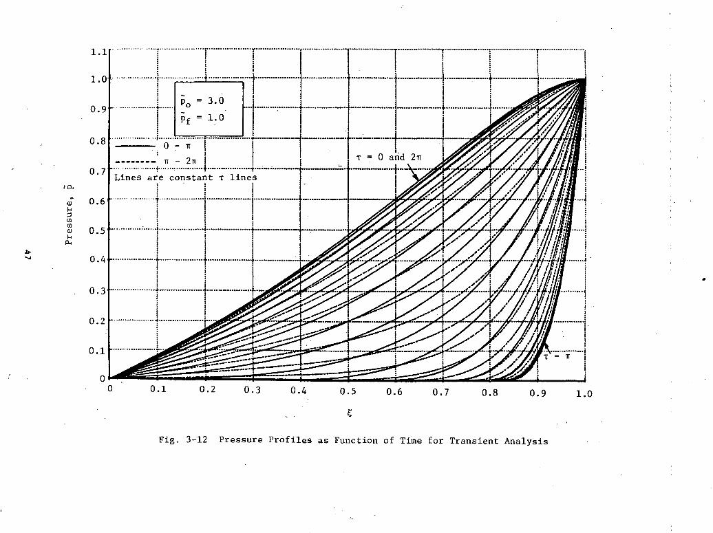
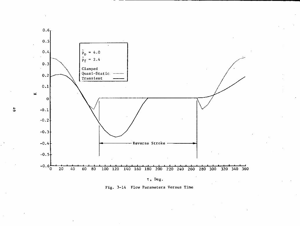
• The flow curve follows the shape of the velocity curve throughout the
cycle, except, of course, when, due to a clamped ring, the flow during
the backstroke is zero. In the particular case of Figure 3-14, the flow,
after peaking at u , became negative at the end of the forward strokem&x(u -* 0). However, upon commencing the backstroke, the ring clamped and
flow ceased.
ovO("1
oCN
ooSCN
•rlH
o
oen
oII
n(0
CO
3
hO
1 H
0)
J<JOMUC/3CUCO)-l<uI
O^oCN
OCN
CN
OoCN
O00
00cup
OOOooo<roCN
co•HuocCM
usCOCO<ucXa•HHIen&0
•H
-mo
42

*% \
\*»
^./•'" 1t
f- (
* \
, \
CO
r-»
O
O
*
*••»"*"•«.""*..,_
""-
o
oCO
o
II II
O
«-id
. 'C
X
„,--'
s;:
'""
vo m
6
co
.»^*
•-..
(4t40
»ri!(40
^-
.+
^f
d
'--.,*«
%
**»
%>"""*•-.
U
UJ
-H0
4J
J
CO
4J
ra '*J
Cen
ai>»
i 1-1
3 -H
0)
a co
cU
0)
f)J
3
HQ
0-
H
"'"'•'
•**
CO
o
*x
^
"*»%
,^
('.Cc1
f+
"'
»•*
CMO
1U*MJoU/>-111>34£.-•
^-
X""--->,
\
\
\\
-
jjf
,y
fsf''
.'''"'••''**•''' •
•''
' "''''
'
. ,
,•H
O
i-l
0
01
•-•' „•
\\
\\ -\\-.1/
-._J
/',••''.
,
CM
f
O
C1
1
ov£>
OCO
0CMOOCO
CM
OvOCMO-3-
CMCM
CM
OOCM
O00
0vOiH0.
OCMi-HOOr-HO00OvOOOCM
1)
60
0)Eto3COI-l(U0)saUflCuoooICOoo•rl

§en8ovOCM
OCM
CM
OoCM
0)Q
SoCM
e•HHCO•HCJ
Cfacn03tneno»o•H.CEfe00
•HPi.
L-l
O
CM
O
o

\ \
000)o
0)
•HHCO3COJ-l0)as'S
-icO
or-lI60•H

oo•
o1/1ofi
OCN
o
oooo
od
CO
o
CM
O
CO•HCOO•H4-1cfl4-1
COCOaO"
V-io0)eBO•Hjjacentoto013COCOCDt-l
p-loo•H
to•HWc<UCOCJ-lO0),gCO•Hi-tOCen0)0)(-13COCO0)6
0•H
47

\
^v^.
111o•H4J!fl
C2
<f
4-1.
.
CO
<r CN
i•HH
II COa
O
«-i 3
i a. icu
o*
| Transient |
1 1
<u•XoJ-l4J
COCUto)-tcu>
1CU
PS
••
ov£>coo<reno(NC
O
o0en
O00
CM
ovOCM
Osi-csoC
MC
M
§ «
s £§
HfHOOr-HO<ri— i
oCN
rHOOrHO00
cu6•HHCO3COcuCN
)u:COCOcfjo-Ht-C«
HB•HCOi™-4ien•oO
fr-
\oomo
•3-o
en•o
CM
O
uiTT
l
oSOO<roCM
OI
ovOoCMfl
OoenoooCM
ovOCM0)
o1-14-1C
fl
CM
OCMCM
OOCM
Ooo
00<uQ
oCMooo00
ca30)CO1-1cu4-101€cfl
oiHfa<•
i-HI00
oCM
VOO
<r on
CM
1-1o
o
o
oo
OI
o
u-l
OOI
ICO
w
WWWCD-COC
JOWWC
OHWw
^rrHmoo10 O
ON
mCMouCQ
CM00
CMOOIIa
HZWCOPi
wwPi
1oiofa
' 0-
i O
-
«
*' C
'<J
' O-**
S3*
' O-
•KCO•HCO-,rHto4-1
I O
.O' a
,
in
co4-1
.•cu
m
ooP
i+
I
CO
00
Ovo
co
mco
<• C
M—
1 rH
rH
O
O
O
• •
oo4-i
CM
r>-
aiP
i O
-3
"
v£> rH
rH
rH
rH
CO
oo oo
r-.1
-1
rH
• rH
O
O
0
CM
O
1•
• •
01P
i +
i
CM
r-- rH
<T O
O
CO
in
vo
CM
>3" vT
^T
O
O
O
COCO
0-
H
O0•
CO
•4-1
CM
00
01 CM
m
*
oo
in*^
vO
^^
co C
M
ino
o
oO
0
0
i i
I
4-1 oo
r~Q
j •
•
Pi .
o
-o
i +
O
CT
* O
00
in
rHO
O
rH
o
o
o0O
NrH
4-J C
O
rHO
IP
i +
I
CM
<•
O(T>
CM
CMco
m
oC
O
CO
C
O
0
C5
O*
COCO
O1
H
orH
o•
CO
00
4-1
<T
rH
0)P
i +
i
-d"
' f***-
I***
f*** r>.
csi**^
vO
^Jo
o
oo
o
o
1 1
1I
I 1m
. O
0
rH0
• C
M
tn4-1
<3" C
M01P
i +
+
00
00
rH
CT* C
O
.O
rH
O
0
0
O
C/3CO
O*
tH
.C
M
0
c01•HCOcn)r-l
Hto4-1
wCOtoo-CO
o-COuCOICO
50

• Variable velocity has the effect of increasing the absolute values of all
flows; that is, even though it boosts both the forward and back flows,
the net flow is increased. Table 3-1 shows this increase to be of the
order of several percent for the case of p, = 0. The high percentage
changes shown for other cases should not be given too much signficance
since they center about very low flow levels when a small variation is
apt to produce deceptively large effects in terms of percentages.
• The pressures are, of course, positive over the entire ring during theT
forward stroke, as shown by the 0- IT range of the constant lines on Figure
3-11. Their magnitude, too, follows the velocity curve. During the
backstroke, fr/2 < T < 3ir/2, cavitation sets in as high negative veloci-
ties are approached (T •* IT); they tend, however, to disappear at the
beginning and end of the backstroke, when the negative velocities are
low.
The inclusion of squeeze-film effects have the following effect:
• The largest film thickness does not occur at u . The peak is delayed
so that it is reached after u . Likewise, the onset of constant hmax
during the reverse stroke does not commence at u = 0, but is also
delayed. Thus, squeeze films have the effect of producing a phase shift
in the film thickness curve. The shift is fairly large, varying from 50°
to 90° in the three cases considered. However, the absolute values of h
seem not to be affected.
• The effect on the flow curves is similar in that there is a phase shift
with little change in their magnitude. Both the forward and net flows
are reduced in comparison to . either the steady-state or quasi-static
solutions; the amount of back flow tends to increase under the influence
of squeeze film forces. Since the quasi-static solution gives higher
flows and the static solution gives lower flow than the constant parame-
ter approach, the inclusion of variable velocity without squeeze film
effects would yield errors of at least 10%.
51
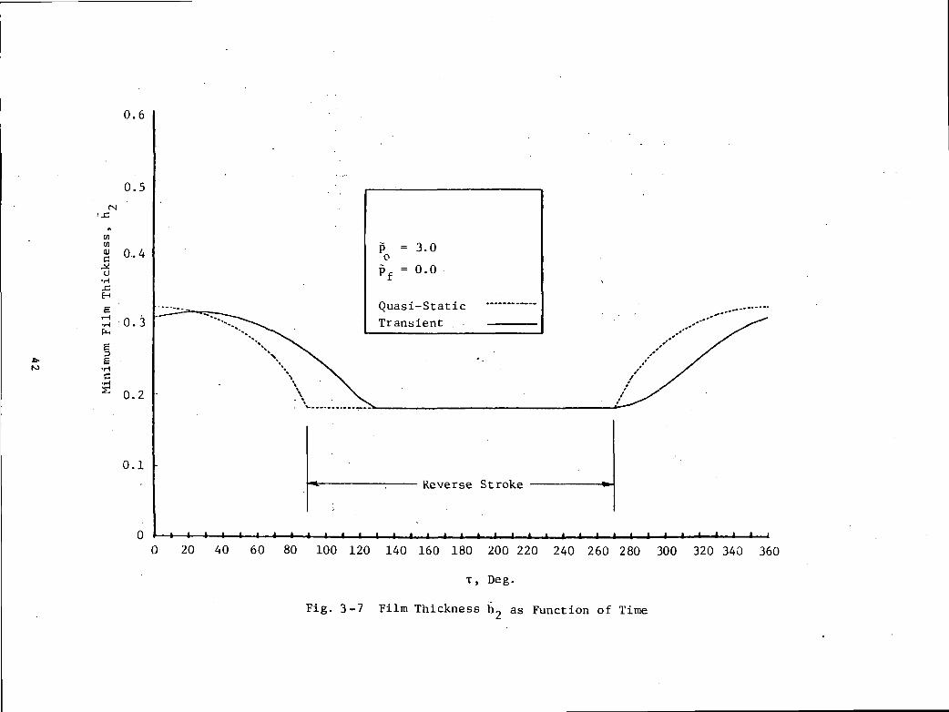
'• Unlike the behavior in the quasi-static solution, the pressure curves
are not identical over the 0-ir and TT-2 halves of the cycle. The pres-
sures are lower when squeeze film effects are included, except over the
latter half of the backstroke, when a closing gap helps to increase the
pressures above those of the quasi-static analysis.
3j3 Starvation
An estimate of the effect of starvation can be obtained by first considering
the clamped case where the area under the bearing land, 0 < x < L, is
predicted to be completely dry at the end of the backstroke. The average film
thickness in this area is Ah/2, and the average Couette flow per unit of
circumferential length is Uo Ah/4. The time, ts, for the starved volume to
fill up would thus be the cross-sectional area AhL/2 divided by the flow per
unit of circumferential length. Thus,
ts = (AhL/2)/(UQAh/4)
The distance traveled prior to flooding is Uots = 2L. This would reduce the
effective forward stroke by an amount equal to 2L. The value of ts given above
will be somewhat low in that it does not account for the development of a
resisting pressure gradient that will occur as the starved volume fills up nor
does it account for any inertial effects in the entrance region that could
impede the start of the filling process. In order to account for these
effects when analyzing experimental data, multiply ts by a factor X which will
in general be greater than or equal to 1. Thus,
seff = s - 2LX
and the dimensionless flow rate Keff becomes
Keff = K (seff/s) = K [1 " X<2L/S>] (3-21)
The starvation process is, of course, much more complex than that treated
here, especially in the undamped case where there is a partial film and the
film is exposed to the sealed pressure, pQ, so that the cavity could be
52

trapped in the middle. In order to understand more fully the influence of
starvation on pumping ring performance, transparent model experiments should
be performed so that the size and behavior of the partial film can be observed
and modeled. In the interim, a simple model was adopted to estimate the
effect of starvation on pumping for either the clamped or cavitating,
none lamped case.
If the film cavitates during the backstroke at 5 = £ , the film thickness at
the point, hc, is
hc = h2 + Ah(l - Cc)
and the void volume (volume of gas or vapor in the cavitated region) per unit
of circumferential length, Vc, would be
Vc = (h2 + Ah - hc) L Cc/2 = L £c2 Ah/2
If it is assumed that the void volume must fill up before significant pumping
can begin and if it fills based on Couette flow at the average film thickness
of the cavitated region, the incoming flow per unit of circumferential length
would be U0 (h2 + Ah + hc)M, and the starvation time, ts, would be Vc divided
by that flow
Ah
As for the clamped case, the effective forward stroke would be reduced by Xuo
ts. If the dimensionless flow in the forward stroke is denoted by Kf and the
backstroke by KR, then
Kf eff = K f (s - AVs)/s
K, 1 - 2A -s + Ah + h2 c
Kf 1 - 2X -L \ Ah 1s /2h2 + Ah (2 - E, )
53
and
Keff = Kf eff - KK (3-22)
For the clamped condition, Kg =0, 5C = 1 and b.2 = 0; thus Equation (3-22)
reduces to Equation (3-21).
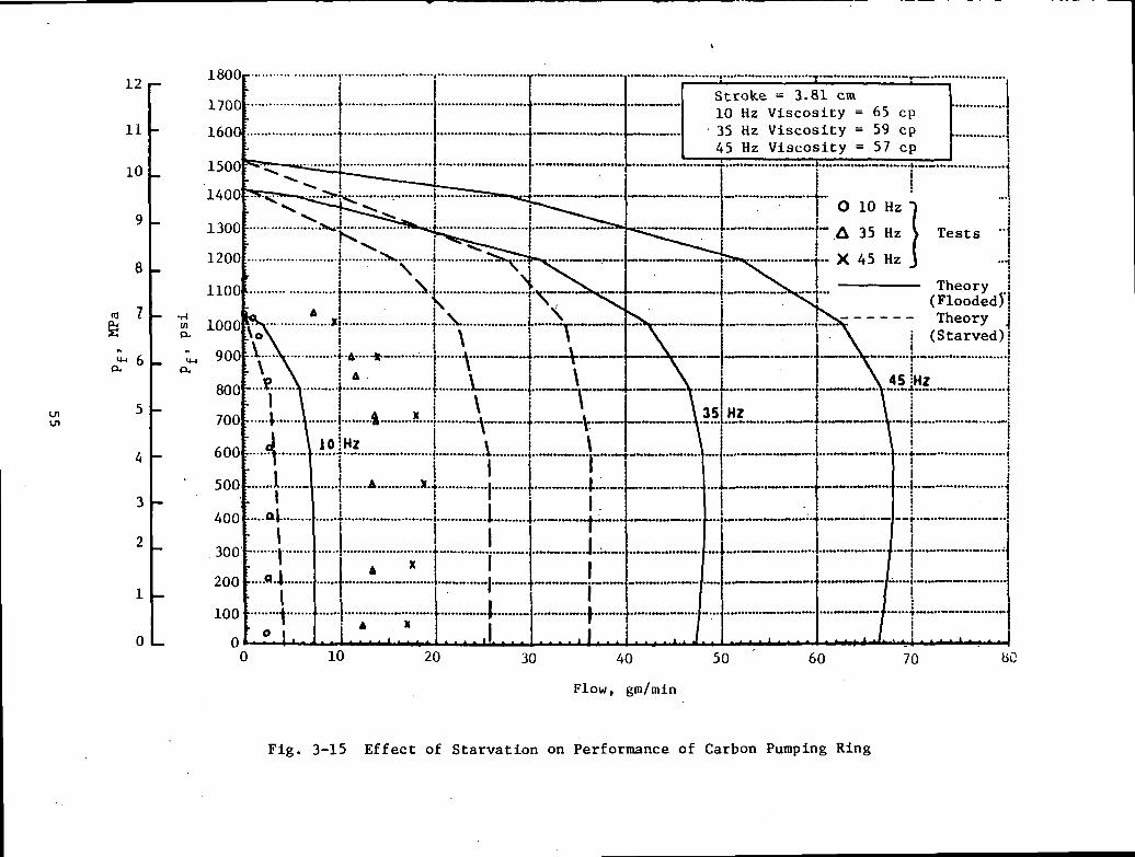
In order to show the effects of starvation, the data for a clamped carbon
graphite ring is given in Figure 3-15. The dotted curves include the effects
of starvation for a value of X = 1. It can be seen that, although the inclu-
sion of the effects of starvation reduces the discrepancy between theory and
experiment, it does not resolve the lack of agreement. The effect of values
of X > 1 will be shown later when comparing theory to experiment.
As a result of the uncertainty regarding the mechanisms of the starvation
process, the effects of starvation are not included in the parametric studies
in Section 4.0. It is recommended, however, that Equation (3-22) be used to
estimate potential effects of starvation when designing pumping rings. The
dimensionless starved net flow is given as an output to the computer program
RING listed in Appendix B of this report.
3.4 Nonparallel Contours
Essentially, the contours considered are tapered surfaces with a constant
slope as shown in Figure 3-16. The reference clearance is that at the trail-
ing edge of the ring; the leading edge clearance is designated by C^. The
slope parameter, 6, is then given by
6 = (dh/dx) = (C - CM)/L (3-23)
In terms of the nondimensional quantities h and £, the slope is given by
6 = (dh/dC) = (C - CM)/C = (1 - O (3-24)M M '
00
•H(*00I104O0)UCDUO<4-iM(UOcdo0)60
o^
o
o00
oovO
oo
o
o
o
o
o
"o
o
" o
oo
o
oo
oo
o
oo
t/1
-3-
mrg
rH
O
<
y>
O
Or
^v
o
ooinoo-»
o
oo
of>
<N
o
oo
Tsd
CNC
O
55

c - cs 'M
St ' (VC)
Fig. 3-16 Geometric Taper on Pumping Ring
56

The clearance ratio CM = (CM/C) in terms of this 6 is then given by:
CM = 1 - L6/C (3-25)
The effect of using tapers on the performance of pumping rings is discussed in
Section 5.0. Briefly, it can be said that the use of tapers has little effect,
except in cases of low clamping load, p , or high values of E, i.e., when thereo
is little elastic deflection of the ring. Clearly, when there is no
deflection at all, a taper would constitute the sole mechanism of generating
hydrodynamic pressures. In practical applications where deflections are
present, the effect of tapers is minimal.
57

4.0 PARAMETRIC STUDY
A study was made regarding the impact of various structural and operational
parameters on the performance of the pumping rings. These parameters include:
• Modulus of Elasticity (E)
• Poisson's Ratio (v)
• Clearance (C)
• Length (L & LI> •
• Ring Thickness (t)
• Taper (6)
• Loading (p and e).
The computer runs that provide the results of the parametric study are based
on the constant-parameter approach without starvation but including the
effects of the backstroke and attendant cavitation. Thermal and transient
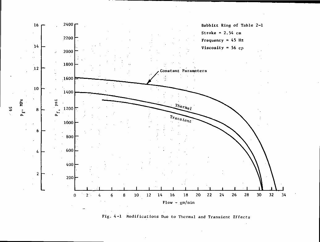
effects were omitted because, as shown on Figure 4-1, their effect is not of
the sort as to qualitatively change the behavior of the pumping ring. The
constant parameter analysis should be sufficient to reveal the essential
features of the parametric relationships without the undue complications of
the more elaborate analysis.
Since it would ultimately be desirable to optimize the design of pumping
rings, the question arises as to what constitutes an optimum. Given the
purposes for which these devices are customarily used, an optimum ring was
deemed to be one which, within given constraints such as reasonable values of
p , C, etc'., can maintain the highest possible sealing pressure without exces-
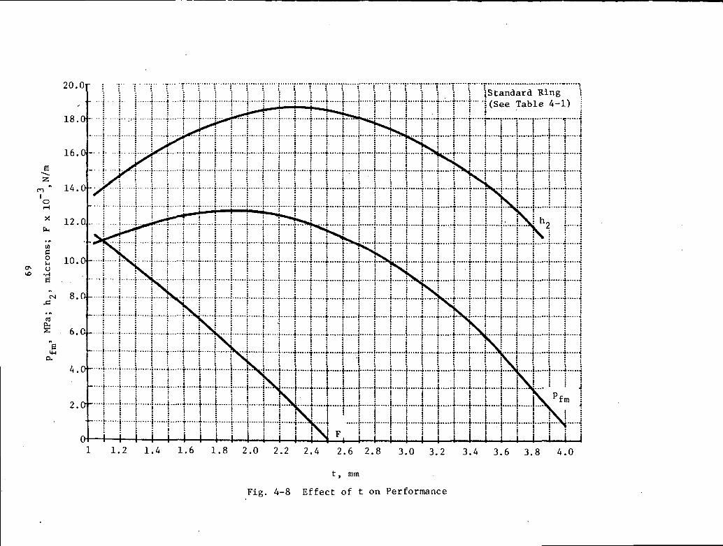
sive wear. This implies the highest values of p~ and a low, preferably zero,
frictional force F. Thus, a ring design which generates high pf and just
clamps shut upon reversing.the stroke would fulfill this criterion. An addi-
tional quantity of interest, perhaps, is also the maximum flow Q. (flow at pf
= 0), that such a ring can produce. Thus, in the plots that follow, the items
of pf, F, and QQ will be the items against which ring performance will be meas-
ured.
The parametric study was conducted by first establishing a standard or refer-
ence design and then by varying its parameters, one at a time, to values below
58
ICMJOtoH
6oj
Uoc•HasJ3XI
BQ
CMii
NXo<U0-IU14
a.uII>%ouen
aoCN
CM
OCM
wXJuwucCflc
C•H6"e"ec^^H
3O
o4J0)
aUl
cou•H
CO
60
•H
OO-a-CM
ooCM
CM
.
OOoCM
OooooovO
ooOOCM
Ooooo00
ooOo
ooCM
isd
cc
59
and above the reference quantities. The parameters for this standard ring are
given in Table 4-1 along with selected departures from the standard set.
Including the standard, most parameters have four computed points from which
optimization plots can be made. The results of the parametric study are
summarized in Table 4-2; more relevant plots are portrayed in Figures 4-2
through 4-11. In Figure 4-4, the reason the film thickness h2 drops with an
increase in clearance, is due to the drop in p, ; a high p, usually helps to
contract the clamping pressure and thus maintain a high ti2« In Figure 4-6,
the explanation for an increase in flow with a rise in length L is that with a
greater L the hydrodynamic effects are increased, and thus, also the flow. As
seen, four parameters, the lengths L and LI, taper 6, and Poisson's ratio have
little effect on performance. Of the two important variables, namely, clear-
ance and clamping force, the first has to be raised above its optimum for
maximum pf, and the latter reduced below the optimum, if large frictional
forces are to be avoided. Since the clamping force is given by the product of
p and e, Figure 4-12 shows the effects of using the same clamping force,
31.96 KN/m (182.5 Ib per in.) of circumference, but by varying the relative
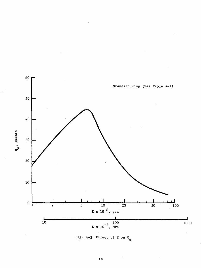
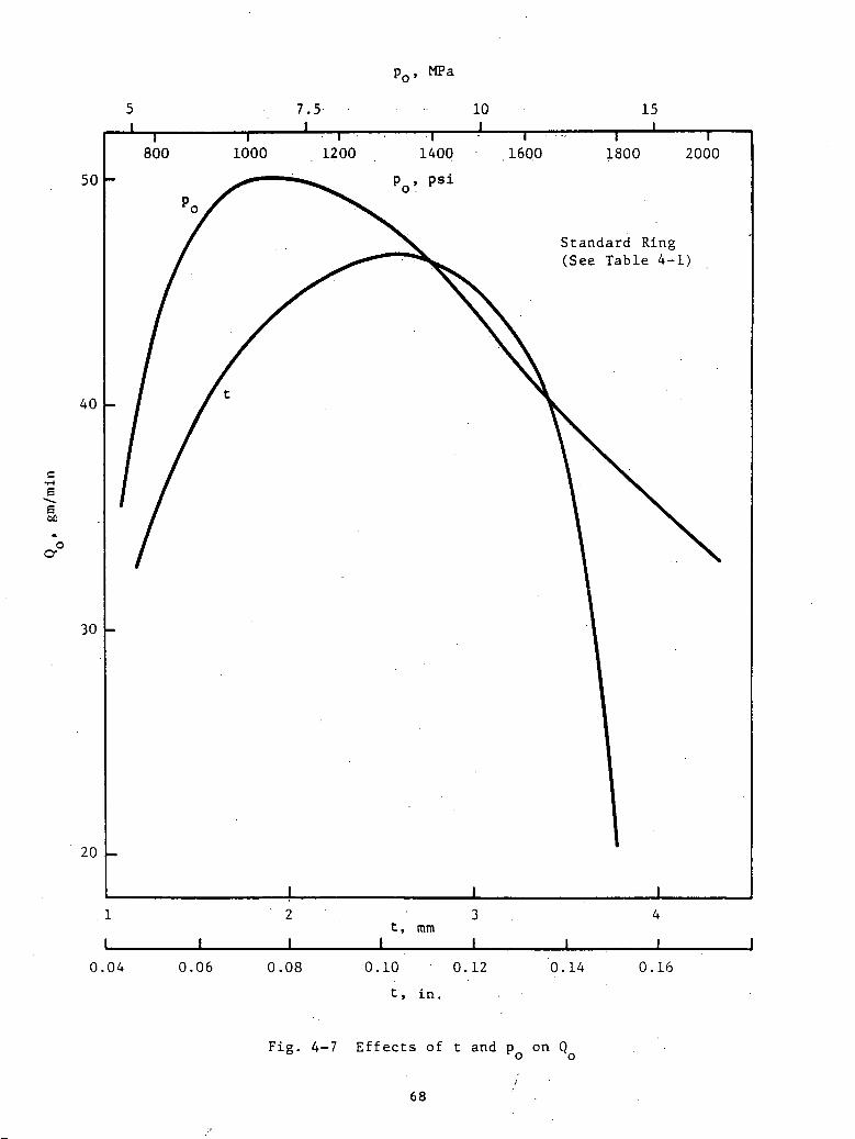
values of pQ and e. As seen, higher values of p^ are achieved when pQ is high,
while higher values of (^ are achieved when e is high. The differences,
however, are not striking.
It should be pointed out that the particular optima recorded in Table 4-2,
such as t = 2.54 mm (0.1 in.), C = 25.4 microns (1 mil), etc., are valid in the
range of parameters characterizing the particular ring specified in Table 4-1.
Thus, for example, for a material with a much higher E value, optimum results
would be achieved with lower values of clearance and ring thickness. The
opposite would be true for a material with a value of E much below the 34.5 GPa
(5 x 10 psi) assigned to the standard design.
60

TABLE 4-1
STANDARD DESIGN FOR PARAMETRIC STUDY
p = 10.3 MPa (1500 psi)
e = 3.175 mm (0.125 In.)
T = 49°C (120°F), u = 59 x 10~3 Pa-sec, (8.6 x 10"6 Reyns)
E = 3.45-104 MPa (5-106 psi)
v = 0.36
s = 12.7 mm (0.5 in.)
f = 35 Hz
R = 12.7 mm (0.5 in.)
L = 6.35 mm (0.25 in.)
LX = 10.2 mm (0.4 in.)
C = 0.019 mm (0.75 x 10~3 in.)
t = 1.9 mm (0.075 in.)
6 = 0
VARIATIONS IN PARAMETERS
C: 0.0063 mm, '0.0127 mm, 0.0381 mm (0.25 x 10~3in. , 0.5 x 10~3in. , 1.5 x 10~3in.)
E: 6.895-103MPa, 20.7-103MPa, 68.95-103MPa, 207-103KPa (106 psi, 3 -106 psi,10-10 psi, 30-106 psi)
L: 5.1 mm, 7.6 mm, 10.2 mm (0.2 in., 0.3 in., 0.4 in.)
p : 5.17 MPa, 6.895 MPa, 13.79 MPa (750 psi, 1,000 psi, 2,000 psi)
v: 0.25, 0.5
t: 1.27 mm, 2.52 mm, 3.81 mm (0.05 in.^ 0.1 in., 0.15 in.)
L 6.35 mm, 15.2 mm (0.25 in, 0.6 in.)
6: -10~3, -2-10~3, -3-10~3
61

TABLE 4-2
OPTIMUM PARAMETERS FOR STANDARD RING
(See Table 4-1)
E
V
C
L
Ll
t
6
PC*
ITEM
psi 10"6
MPa 10~3
mils '•-••--!» ••
microns
in
nun
in
HUfl
in
nun
F .'•
psi
MPa . ;
RANGEEVALUATED
1 - 30
6.89 - 207
0.25 - 0.5
^0*25 - 1.5
6.35 - 38.1
0.2 - 0.4
5.08 - 10.16
0.25 - 0.6
6.35 - 15.2
6.05 - 0.15
. '1.27 - 3.81
0 - (-3-10"3)
750 - 2,000
5.17 - 13.8
For Pfm
SUBJECT TO F=0
5.5
41.3
No Effect
1.0
25.4
No Effect
No Effect
0.100
2.54
No Effect
; HOG
7.5
FOR Q
6
41.3
.. No Effect
1.0
25.4
Highest
No Effect
0.102
2.64
0
1050
7.20
^ ..„*See.. Also...Fig. 4-12.
62

50 ._
20
I 10
E x ].0~6, psi
10E x 10~3' MPa
LOO
Fig. 4-2 E f f e c t of E on Performance Standard K i n g (See T a b l e 3-1)
63
60
50
Standard Ring (See Table 4-1)
•HE
oc
40
30
20
10
10
I I10
E x 10~6, psi
I
20
100E x 10 , MPa
50 100
1000
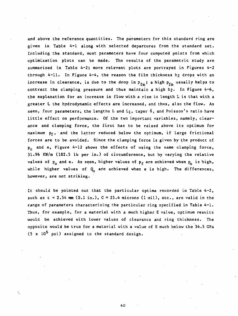
Fig. 4-3 Effect of E on Q
64

COeo
(UuMOM-l
OCJo0)oo
•H
65

OC I
G
<t
« H
T3C
4)eg
<u
csJS
—
oo
oCV
i
' 0
1 x
d
isuoaoxffl «'
w *"*
cuaoM-l
(JcuCohJoo<uwmI00
66

L, mm7.5_J
10I
17.5I
60
50
•He"s00
40
Standard Ring(See Table 4-1)
30
I I I I I
10 15 20 25C, microns
30 35 40
Fig. 4-6 Effects of C and L on Q
67
7.5I
10 15
I800 1000 1200 1400 1600 1800 2000
50
40
ci-iE
1
30
Standard Ring(See Table 4-1)
20
It, mm
I I
0.04 0.06 0.08 0.10 0.12
t, in.
0.14 0.16
Fig. 4-7 Effects of t and p on Q
68
<L '
6 •'-
cLO
oo
vo <r
CNCM
r-I
(H
r—I
i—!
' cL
.' A
'
el '
<L . ' <L
* O
T x
J i
O
. 00
vO
7 ,ui5
C "ji
• o
T
T T
*
t
e
CDOCOtuuOl
COo01U
-l
ooIoo
69

<JC I
c ^•HP
i 01
I-, eg
ed H
T3G
<Uto
a)4J
1/1
en ^
!••
4im
m
i
oC\i
' 0
1 x
d • suoaoxui
<cq
O
uOu-iM(UP-OQ.
HU-JOCO
4-1OOJ
M-l
WONoo•H
70
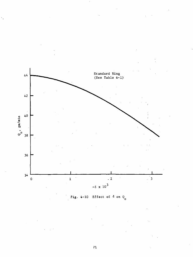
44 Standard Ring(See Table 4-1)
42
e•HEIs60
38
36
34. 2
-5 x 10'
Fig. 4-10 Effect of 6 on Q
71

acO14-1t-t
C-o
« a
p-j
q_|
S
O
"
4J
C
OU
. 01y-i
Woo•H
' 0
1 x
I isuoaoT
ia ' cq
iujjq *
72

pf, MPa
1015
Standard Ring
(See Table 4-1)
6.895 MPa
A.63 mm
13.8 MPa
2.31 mm
5001000
15002000
psi
Fig. 4-12 Combined Effect of p and e
73
5.0 EXPERIMENTAL PROGRAM
Following the optimization of the candidate rings, tests were run on three
rings to verify their performance and their agreement with theoretical pre-
dictions. The test rig and the experimental procedures were the same as those
used on the tests described in Ref. [l].
The pumping ring program, given in Appendix B based on the analysis performed
here, has been used to select ring designs for experimental testing. Initial-
ly, a set of studies was performed with steel, babbitt, and Rulon J rings as
examples of a high, medium, and low modulus pumping ring. Overall dimensions
were selected consistent with the experimental test rig. The principal design
variables to be evaluated within the applied pressure, p , the clearance, c,o
and the-average thickness, t. A target value of p . of 1500 psi was used;o
however, it was found not feasible to design to this pressure with the low
modulus Rulon ring. Sample geometries that have been arrived at are shown in
Table 5-1. The general configuration of the pumping rings submitted for test
is shown in Figure 5-1.
The principal criterion used involves being able to significantly deflect the
ring to obtain pumping action without excessive clamping during the back-
stroke, which would result in excessive wear.
Based on the criterion above, the design of the steel ring would require rela-
tively small thickness and a small clearance to obtain suitable compliance and
deflection characteristics. The tolerances required seem excessive for the
present application, and it is thought that steel rings would only be applica-
ble in situations requiring much higher pressures. It was thus decided to
confine testing to medium and low modulus materials ranging between babbitt,
carbon graphite, and Rulon. The test rig and experimental procedures were the
same as those used on the test.
One problem area revealed in the course of testing concerns the clamping load.
Difficulties were encountered in testing the carbon and Rulon rings, and often
such attempts at testing led to breakage of the specimens. It was also noted
that some of the babbitt rings were severely worn, not at the downstream end
74

\1
ta
S\ss\
!
]I2 -a
COo•H0)C00C00C•Ho.§Du
oo•HCO
TJOIu-)00
•HCM
75
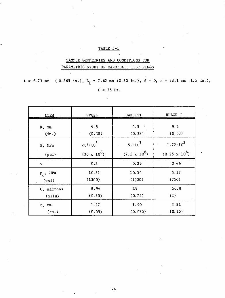
TABLE 5-1
SAMPLE GEOMETRIES AND CONDITIONS FOR
PARAMETRIC STUDY OF CANDIDATE TEST RINGS
L = 6.73 mm ( 0.265 in.), ~L = 7.62 mm (0.30 in.), 6 = 0 , s = 38.1 mm (1.5 in.),
f = 35 Hz.
ITEM
R, mm
(in.)
E, MPa
(psi)
V
p , MPa
(psi)
C, microns
(mils)
t , mm
(in.)
STEEL
9.5
(0.38)
207-103
(30 x 106)
0.3
10.34
(1500)
8.96
(0.35)
1.27
(0.05)
BABBITT
9.5
(0.38).
51- 103
(7.5 x 10⁶)
0.36
10.34
(1500)
19
(0.75)
1.90
(0.075)
RULON J
9.5
(0.38)
1.72-103
(0.25 x 10⁶)
- 0 . 4 6
5.17
(750)
50.8
(2)
3.81
(0.15)
76

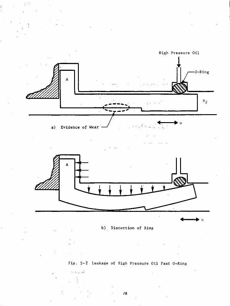
where wear might be anticipated but far upstream, ahead of the actual pumping
area, as shown in Figure 5-2a. This led to the conclusion shown in Figure 5-2b
that the high-pressure oil used for clamping leaked past the 0-ring and, by
pressing against bracket A, effectively produced a sealed chamber over the OD
of the ring. The pumping ring was thus loaded with a pressure, p , over theo
entire length (L + L) instead of only the narrow region, e, covered by the
0-ring. This unpresidented pressure loading gave the ring the flared shape
shown in Figure 5-2b which led to high wear upstream of the active pumping
area and to breakage of the weaker rings.
The problem was resolved by opening relief passages behind bracket A so that
any fluid leaking past the 0-ring would be scavenged outside. Since the leak-
age past the 0-ring occurs only when p. approaches p , such leakage should not
affect the build-up of sealed pressure p at levels below p . With the relief
grooves in place, all unsatisfactory tests were repeated; no further difficul-
ties in testing the Rulon and carbon rings were encountered. It should also
be noted here that the sealed pressure p was not observed to significantly
exceed the loading pressure p . This is believed to be a result of leakage
past the 0-ring, which occurs when p starts to exceed p , as indicated in
Figure 5-3.
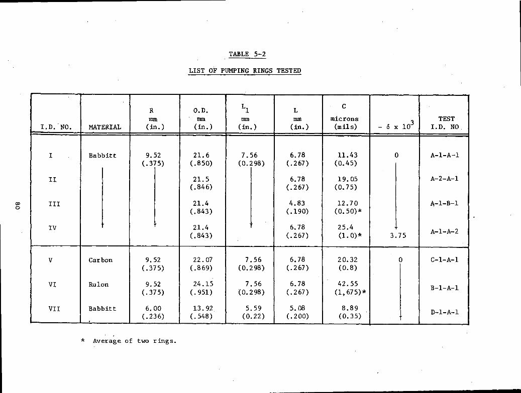
The rings tested were made of either babbitt, carbon graphite, or Rulon. The
geometry and dimensions of the various rings tested are as summarized in Table
5-2 and, except for one item (Item VII), had the following two dimensions in
common:
Shaft Diameter - 19.05 mm
Inside Diameter of Back Section (over length L ) - 19.3 mm
The viscosities of the oil used are those given in Figure C-l of Appendix C.
5.1 Tests with Large Babbitt Ring
The 19.05-mm diameter babbitt ring was tested at three frequencies, 60, 35,
and 10 Hz, and at two strokes, 50.8 mm and 25.4 mm. The parameters investi-
gated were the pumping ring length (L), clearance (C), and the effect of a
taper (6). Tables C-l through C-4 in Appendix C give the detailed results of
77
High Pressure Oil
0-Ring
a) Evidence of Wear
b) Distortion of Ring
Fig. 5-2 Leakage of High Pressure Oil Past 0-Ring
78

Housing
, 0-Ring
Pumping Ring
Leakage Paths
Fig..5-3 Schematic of Leakage Past 0-Ring atHigh Sealed Pressures
79
CNImw
sHC/}
WHcnOzo2.bOHCO
OH
Z
W
.EH
QM
cnorH'O1
cmicrons(mils)
X—
\
H. 15
^.ix-x
O
x—'
.,1
MATERIAL
oKQM
j
•H
,-H
rH
CN
'I
I
1
II
I 1
rH
CN
rH
rH
1 1
1
Ir-~cn
•K -K
cn X-N
in
X-N
o
X-N
X-N
<r m
O
m
r-» o
s
j-O• *^*
• f^ • in
* *
rH
•
OS
.
CN
•
m i-l
rH
O
rH
O
rH
O
CN
N
wX
N
^X
X
» X
OO
P* oor»-
cno o
or^
• C
N
• C
N
• rH
• C
NvO
•
vO
•
<^
• vO
•
oo
r-x! o"
vo o
iri ^o
<• cn
NT
cnrH
oO
rH
OO
rH
OO
rH
OO
CN
•
CN
•
CN
•
CN
•
CN m
• mO
S
.
4-14J•Hf>MPQ
1
Mt-l
I-l
>M
M
M
M
rH
rH
rH
4: 4s
4si
i i
i i
i
* X— s
x—v
CN x— \ m
m
os m
cn oo in
r.
oo cno
o
C
N •>
oo
oC
N >-'
-* rH
^
**-s
s-*>
x— s
s~*oo
f^ oo
r*^ oo
^—^
r^ v
o
r^ x
O
o
o•
CN
.
CN
•
CN
\o
t ^o
•
in
•
\&
00
^&
00
O
S C
Nm
os
in
os m
CN
• C
N
• C
N
• •
r»- •
r^» «
m
o0
0
-~
s
r>- x-v in
X-N
C
N x-x
O
OS
rH
rH
O
v 00• \&
• in
• x3-
CN oo ^J
c?s cn
LnC
N
• C
N
• rH
'
X^
X* X
X
— X
CN m
CN
m
o vo
in r-»
m
r-»
O m
• cn • cn
« CNO
s •
Os
• vO
•
4JC
4-1
O
C
"HX
I O
X
II-l
H
X)
cd ^
cdO
P
rf P
QMM
M
M60
a§4J
14-1Oa)
. oort
80

Che tests. The self-pressurization runs represent an arrangement in which the
clamping pressure was provided by the sealed pressures generated by the pump-
ing ring. This represents the case of p = p at any instance. It turned out
that, in order to start the untapered pumping ring, a priming pressure was
required (that is, when at the start, p_ = 0, no self-clamping was possible).
Some initial p > 0 had to be provided by external means in order to enableto
the pumping ring to apply self-pressurization and build up a pf beyond the
initially supplied priming pressure, p. . The tapered rings were found to be
self-priming.
With regard to the effect of the several variables tested, the plots suggest
the following:
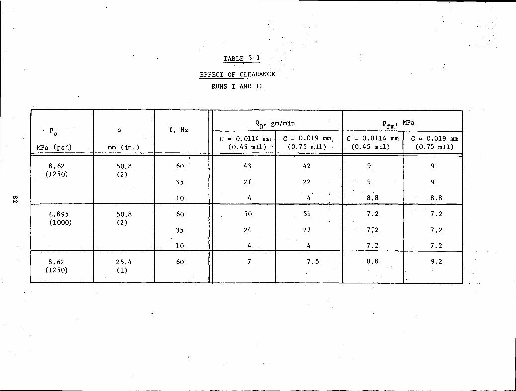
• Effect of Clearance - Table 5-3 shows the changes in maximum flow and
pressure induced by changing the clearance from 11.4 microns to 19
microns. These changes are minimal, indicating that the optimum lies
within the range of values.
• Effect of Length - As shown in Table 5-4, there is a definite advantage
to a higher length, L, with regard to maximum flow rates; but the
shorter rings produced higher maximum levels of sealed pressure, p .f m
• Effect of Taper - Table 5-5 confirms what can be intuitively deduced as
the desirability of having a geometric taper. At high clamping pres-
sures when ring deflections are large, the geometric taper is counter-
productive. However, at p = 3.45 MPa, a taper produces higher flow
rates and higher levels of maximum pressure.
5.2 Tests with the Rulon and Carbon Ring
The detailed results of the tests on the Rulon and carbon rings are given in
Tables C-5 and C-6 in Appendix C. In both rings, the higher clamping pres-
sures produced higher reservoir pressures, p , but the lower values of ptm o
yielded higher maximum flow rates. This trend was already noticeable with the
babbitt ring, but as the value of E drops, it becomes more pronounced so that,
81
roIm3faO
cd*eac•600O
"
iH
Oo r~
-
II 0
u|-* l-t
SJJ
O -tf
II 0
u
I-lO
N
"H
3
e•
mO
r»
II 0\~s
rH
o m
d "*.o
u —
'0
N3C
.g
to ^•HW
0
£a.
cd
00
ON O"*
oO00
^^ o^
oo
CM
C
M
-vtvr
CM
co
iH
«*
-* C
M
o
m
o^>
ro
iH
00O C
Mm ^
CM
O^o
in• C
M00 i-l
CM
C
M
CM
•
•
*
r
r- i-s.
CM
C
M
CM
rH
r~
<•
m
CM
O
-J-
-AT
m
CM
o
m
o*O
C
O
i-l
00O C
Mm ^
m o
ON
O00
O
• i-H
CMON •
0000mr-oin I-H
CM
*~*
CM
Ovo
m• C
M00
rH

TABLE 5-4
EFFECT OF REDUCED LENGTH L
RUNS I AND III
POMPa (psi)
6.895(1000)
3.45(500)
8.62(1250)
s
mm (In. )
50.8(2)
50.8(2)
25.4(1)
f.
Hz
60
35
. .,10
60
35
10
60
QQ, gra/min
L=6. 78 nnn(0.267 in.)
50
25
.4
59
28
3.5
70
L=4.83 nun(0.19 in.)
34
17
2.5
51
27
3.5 .
60
. Pfm' **a
L=6. 78 mm(0..267 in.)
7.2
7.2.
7 .2-
3.8
. 3.8
3.8
8.8
L=4.83 mm.(0.19 in.)
7.8
7.8
7.0
7.2
7.2
7.2
8.0
83

TABLE 5-5
EFFECT OF TAPER
RUNS I AND IV
'f
PoMPa (psi)
8 . 62(1250)
6.895(1000)
3.45(500)
8.62(1250)
s
mm (in.)
50.8(2)
50.8(2)
50.8(2)
25.4(1)
f. Hz*
60
35
10
60
35
10
60
35
10
60
QQ, gm/min
6 = 0
42
22
4
50
24
4
60
28
4
7
6=-3.75-10~3
32
17
4
42
18
2
> 80
38
4
2 .5
Pfm, MPa
6 = 0
9.2
8.9
9.2
3.8
3.8
3.8
8.8
6=-3.75-10~3
9.2
9.0
7 .2
7.5
4.2
4.2
3.8
8.8

for the Rulon rings, Q at p = 1.72 MPa (250 psi) is two or three times the
value of Q at p = 5.17 (750 psi).o o
5.3 Tests with the Small Babbitt Ring
The results for the 6-mm radius babbitt ring are given in Table C-7. The diam-
eter was reduced roughly 1/3 as compared to the large rings. Neither the
flows. Q , nor the maximum sealed pressure, p. , were much affected by theo tm
change in size.
85

6.0 DISCUSSION OF RESULTS
Three sets of comparative results are presented in Appendix D.
• The babbitt rings, which comprise the large size with two different
clearances and a small size ring
• The carbon graphite ring
• The Rulon ring.
The theoretical curves presented in Appendix D were obtained without the star-
vation correction and without allowance for the fact that the sealed pressure
does not exceed the loading pressure due to leakage past the 0-ring.
|
A number of qualitative conclusions can be drawn from a study of the figures
in Appendix D. The major discrepancy observable is the fact that the measured
flows are substantially smaller than those predicted by theory at zero sealed
pressure. This is believed to be partially due to effects of starvation as
will be discussed later. For practical purposes, this discrepancy is not
believed to be a major one in that the pumping rings will normally be used to
develop a buffer pressure as opposed to being designed to deliver prescribed
flow rate. The predicted maximum developable pressure at zero net flow was
found to be in better agreement with the experimental data. Again, all of the
curves that predict sealed pressure higher than the loading pressures should
be truncated at the loading pressure value due to leakage past the secondary
seal.
It is important to note that all of the data presented in Appendix D was
obtained with seals that were sized and designed with the analysis contained
Here. In all cases, as predicted, the seals did perform the task of develop-
ing and maintaining the designed sealed pressures. Significant pressures
could not be developed for steel rings where the theory indicated that suffi-
cient deflection would not be obtainable to provide adequate pumping.
Although the analysis presented so far does not accurately predict deliverable
flow, it can be used reliably to size and design pumping rings. In order to
obtain and improve fit to the flow data, a two-constant empirical relationship
has been determined from the data for babbitt pumping rings to attempt to
86
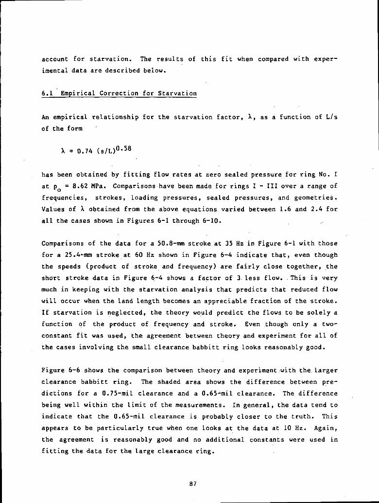
account for starvation. The results of this fit when compared with exper-
imental data are described below.
6.1 Empirical Correction for Starvation
An empirical relationship for the starvation factor, X, as a function of L/s
of the form
X = 0.74 (s/L)°-58
has been obtained by fitting flow rates at zero sealed pressure for ring No. I
at p = 8.62 MPa. Comparisons have been made for rings I - III over a range of
frequencies, strokes, loading pressures, sealed pressures, and geometries.
Values of X obtained from the above equations varied between 1.6 and 2.4 for
all the cases shown in Figures 6-1 through 6-10.
Comparisons of the data for a 50.8-mm stroke at 35 Hz in Figure 6-1 with those
for a 25.4-mm stroke at 60 Hz shown in Figure 6-4 indicate that, even though
the speeds (product of stroke and frequency) are fairly close together, the
short stroke data in Figure 6-4 shows a factor of 3 less flow. .This is very
much in keeping with the starvation analysis that predicts that reduced flow
will occur when the land length becomes an appreciable fraction of the stroke.
If starvation is neglected, the theory would predict the flows to be solely a
function of the product of frequency and stroke. Even though only a two-
constant fit was used, the agreement between theory and experiment for all of
the cases involving the small clearance babbitt ring looks reasonably good.
Figure 6-6 shows the comparison between theory and experiment with the larger
clearance babbitt ring. The shaded area shows the difference between pre-
dictions for a 0.75-mil clearance and a 0.65-mil clearance. The difference
being well within the limit of the measurements. In general, the data tend to
indicate that the 0.65-mil clearance is probably closer to the truth. This
appears to be particularly true when one looks at the data at 10 Hz. Again,
the agreement is reasonably good and no additional constants were used in
fitting the data for the large clearance ring.
87
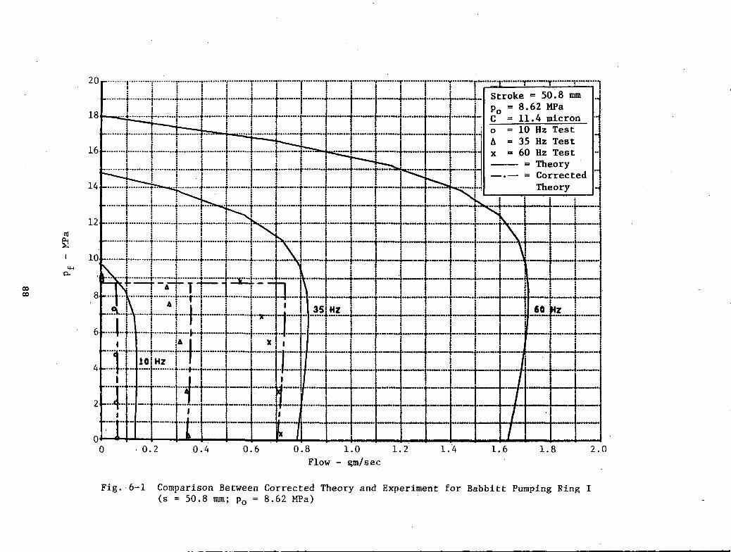
: I1
i i
.._..
t>cB•HPS60
•Ha3PUc0)B•HcC3O1)0) n]
U<U
U 0
0
C
II<U<l>
OS
a4JQ)
•#>
co o
oto
••H
o
)-i mcoC
u II
O
U3
GO
•H
88
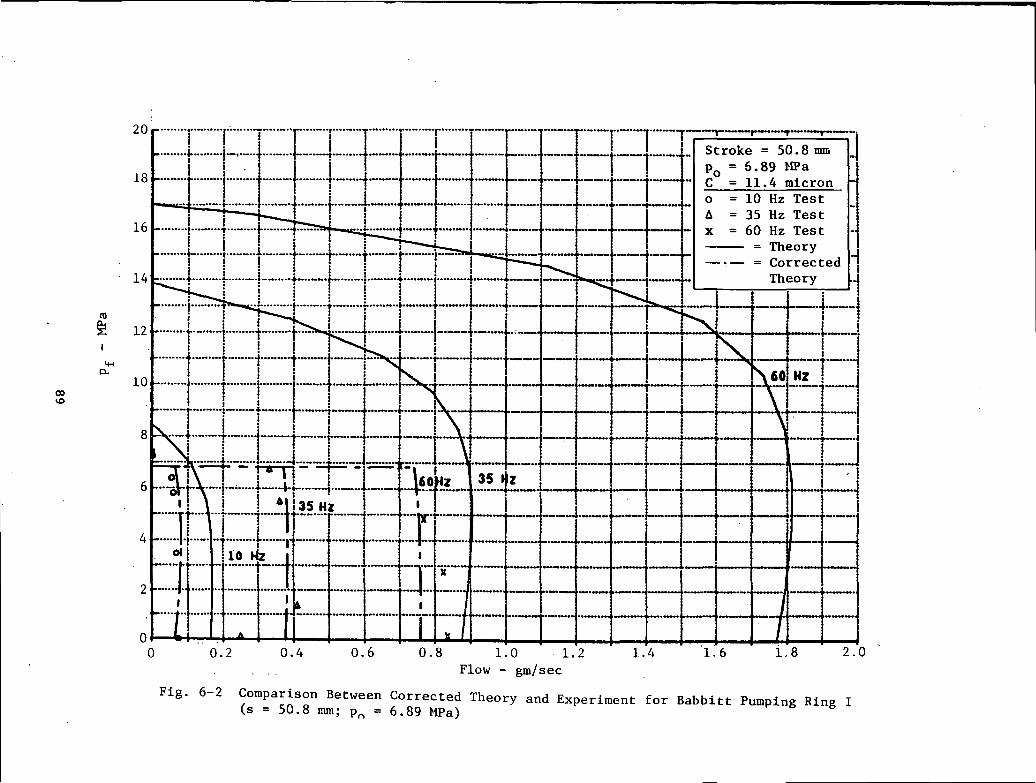
00
•HOS00c•Has•H.0•§PQOU-lC0)
•HVj
0)C
XXwT)Ccfl
O0)
HT3
^-x<U
a)^J
p.
QJM
a\M
CO
O
•O
vo
C
II0)0)
C3
a
CO CO
03 •
•H
O(j
u-i(fla
,,o
enu
-^
CMI
\O00•H
89

oce•HOS00c•HI. 4-1
t-l•HCOCQl-t0i•H>-<u&uoOJ
U P
")
C
II0)01
o3
D
.•UQ
) .J
.
co ooto
••H
.O
a. iio cou
ivO
90
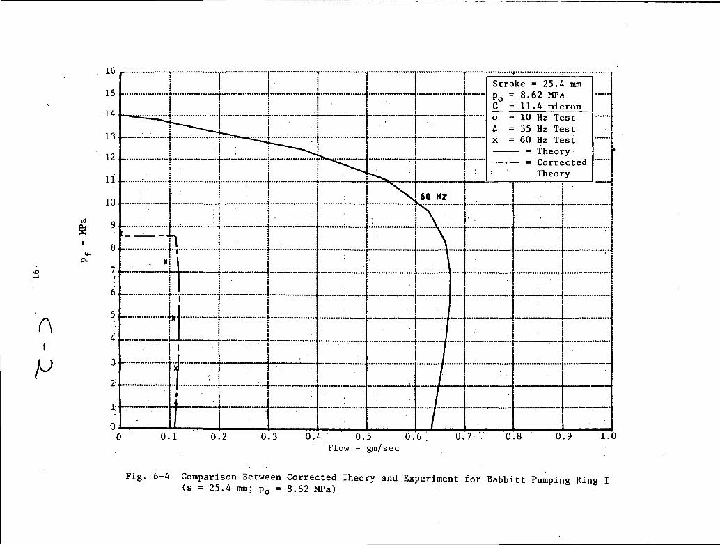
CMII0)o4J
W
oM0)
OP
4 *iH
CM
>3-\Q
.
• r-l
00
i-H
II II
Oa u
CO CO
<U a)
H
H
N
N33
33
T"
ca0)HN33'
CvO
n u
n
o <
T3<U4J
X
CJ >
,)-l
0) (-1
O
>-i
O0)
h
01
.c
oH
CJ
II II £
i :!
!•i
-
:•
j
:i!;
OO
or-O
o!DCO
m
soo
io
00c•H60G•HI0--Q&CO
ia)exXCCOO(UH•a<ut-l C
NI
(-1
VO
O
•u
oo
CQJ
Q)
Oa0)
.»
co -*
CO •
03CX II
O
CO
U ^
00
•H
COiri
• • V
3-
91

ooc•t-(OS60C•Ha.§PuOu-ida)6•H)-l
01a.X"acoatHx-*
\
•a co
a) a,
o o
C_J rH
C
IIa>0)
O3
a4-10)
..
O O
OCO
••H
O
a. no
wu
•*"
60•H
92

O<UCO00O
ooC•H00c•HI.aa)CQt-lO0)
CuXWT
3OOJ
HT3a)4JO<u
CN
vOoo
a;oex
aiP9co ooCD
••H
O
aovOI00
93
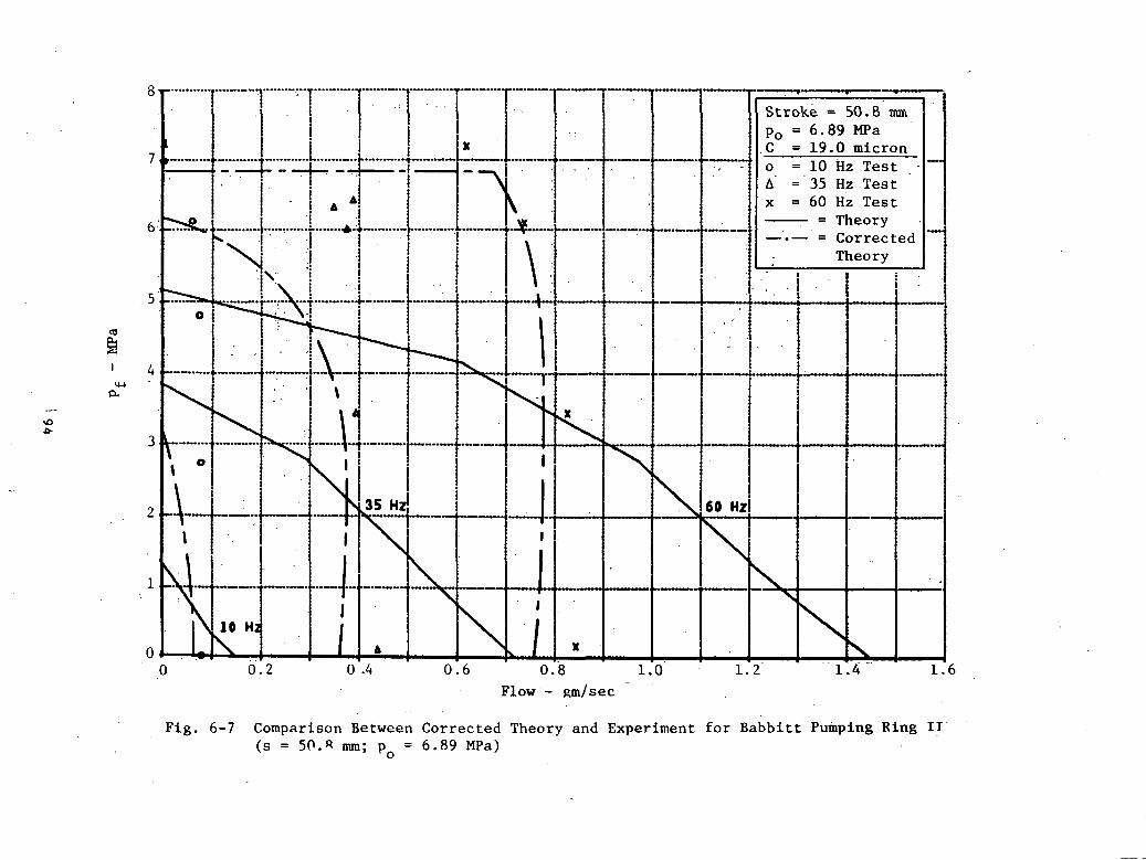
.o0)COor-l
00C•HOS00C•HIXI«PQUOM-l
i•Hl-<Uo.Xwo<uH-O<u)-i coo
•O
vO
C0)oP..
4-1Q
) ..
" 1
Co ocCO
•H C
)-l m
0.
II
o coU
v^
00
- Jd
I 94

6
CE
0u
sr co u
u"i g
£
CNC
N
OII
vo
•
0) 00
iH
O
II II
4J O
CO O
. O
4J 4J
J->co
co co ;cu
cu <
u i
T30)
•u.^
CJ >
»-i
<U
t-iH
H
H
O
>
•<
OCU
M
01N
N
N
j: O
£S
E
C 5C
H
U
H
o m
o
ii nt-H
C
O
vO
n II
n
O <
X
111
U0)CO
1
00C•H0300C•Ha.
paMoi•H1-1(Up.
TJC03o0)
H
ot-H
CUpti
4j
o o
oc
n0)(II
O
0) •«
poCO(0O-
II
a co
coivO60•H
95

2
i °•-
ooo
eu -r-io
2
E
ii •
•O
CM
0)
p-t
-H
O
II II
W
& C
J
0) •
4_, u
4_|
4-J
M
CO
0) O
>p
H r-
H ^ O
N ^3
N ° £
O
u^ O II
r-i en vo .
ii n
ii ]
O
<
X
1
r11-•o«m
^ v,
•OT
X
<
IB
HB
B m
0
X
T?
<
O
©
' -•
X
>
••
»•_
II
•-!.
C
cEafl
0)4JtOO
soc3a.O0)
T3CJ1-3 O
= II
1)-J O
3 a
'0
O. I
o en
Pumped Pressure - MPa
96
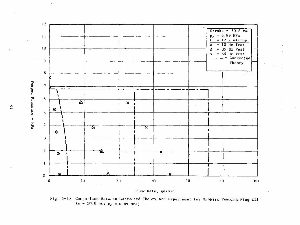
'
1e
c£
ouC
O
CO
U
c s
"e1/1
ON
r-x
II O
C
•
Qj
1O
'H
O
II II
U<-> O
C/3 p
f^
T30)
tn cn
uj ^j ^
5-1
H ^ £
<
U
S X
K"
H
o m
o "
r^ fO
\C
l
II II
II*
(
V
' r'
t,1'1j'"
_tm ^
^^^
X.
<l
o
••
^H
Ma
BI
^M ••
mat
_H
— ^ *
, «
«^M
XM^ «o
IM
-Si
__ —
-
0
__
—
^0»
^»
'
•
_
^•M
BE
n «
1•J
*
0
— «
»«X
»
^^M
MM
^'
7;
w
^
M
00
C0600
•HCX
-—i
f*— .
M^
U,
iJ&J
>.«
•^3=c*_l
u_
o
ti^ T
i*rt
e g-
's ^
"s" ~
00 =n
f~™*
fl) ^>
^
*J
nto
Cpw
^ O
3
^f-H
"H
-s
!*, o
to" 0
.w
Z1J"
JN
u oo
.9 •
^ = n0)a
c3
0.
^_j
QJ
• «
» S
-
i5 <o•-
O•- in
0
WC_J
^^
c1vC
(-5
oo
Pumped
Pressu
re - M
Pa
97
Figures 6-9 and 6-10 show comparisons between theory and experiment for the
shorter length ring. The increased discrepancies indicate that the starvation
correction depends more on the stroke than on the seal land. This could be an
effect of inertia in the inlet region. In general, the starvation correction,
along with the constraint that the end pressure doesn't exceed the loading
pressure, provides much better agreement between theory and experiments but is
still somewhat incomplete.
6.2 Effects of Viscosity
Since the viscosity cannot be measured at the interface (it is, in fact, meas-
ured several inches upstream of the inlet) and since the clearances are very
small, both parameters could, in actuality, differ from the assumed values.
Major reductions in viscosity, such as that which would occur if the actual
temperature were 100°F higher than the measured inlet temperature, would
provide remarkably improved agreement between theory and experiment. This
fact was observed in numerous parametric studies which are not presented here
in that no justification has been found for this temperature rise.
6.3 Suggested Design Procedure
The most effective use of a pumping ring is believed to be for generating a
buffer pressure to back up another seal. Thus, if one were to seal gas at 10
MPa from oil at ambient pressure, the pumping ring should be used to develop
the 10 MPa backup pressure in a buffer reservoir, thus alleviating the pres-
sure gradient on the primary seal. This should provide prolonged life for the
sealing system since the pumping ring is essentially a "light contact" device.
Clearances should be selected based on shaft diameters and machining toler-
ances. Values of C/R should be of the order of 10" , thus resembling bearing
clearances rather than the tight clearances (or interference) that one would
generally find in a seal.
The loading pressure should be of the order of the desired buffer pressure.
Back leakage past the 0-ring could thus provide a potential relief valve to
protect against excessive pressure buildup in the buffer chamber.
98
The computer program RING (given in Appendix B) should then be used to arrive
at a combination of material properties (E, v) and geometries (t, e, L, LI) so
that the computed value of Pfm is equal to the desired buffer pressure, and a
small amount of clamping is predicted to occur during the back stroke. Allow-
ances should be made for some wear to occur due to friction resulting from the
radial shear force F. .
If the pumping ring is designed to generate its own loading pressure, p, = pf,
an initial taper should be used. Values of CM/C of the order of 2-3 have been
shown to be adequate for obtaining self-pumping without the need for external
priming. Caution should be used here in providing pressure relief to avoid
overloading.
Finally, if the pumping ring is used as a flow device, rather, than a pressure
generator, allowances should be made for the fact that the analysis tends to
overpredict flow under many circumstances. In general, the "starved net flow"
prediction generated by RING should be within a factor of. 2 of the flow that
one would expect to obtain in practice, based upon the measurements reported
here.
99

7.0 CONCLUSIONS
A design analysis has been developed for predicting pressure-flow relation-
ships for various input geometries, speeds, fluid viscosities, and elastic
moduli of pumping rings. The analysis can be used to size and design pumping
rings for various applications. Results of testing with Rulon, babbitt, and
carbon-graphite rings at various loads, speeds, and geometries indicate that
the analysis can consistently be used to design rings that work well over a
fairly broad range of parameters.
The design criteria for selecting the clearance would be dictated by tolerance
and flow rate consideration. The applied loading, p , should be the order of
the desired pumping pressure. The choice of materials and geometry are then
dictated by elasticity considerations so that the deflected ring, under static
load, clamps the shaft with a very small force to nearly eliminate the back
.flow without resulting in excessive friction and ensuing wear and power loss.
The greatest discrepancy between theory and experiment lies in the prediction
of flow at zero sealed pressure, Q . Predicted values of Qo are substantially
higher than those observed experimentally in almost all cases. Predictions of
the maximum sealed pressure at zero net flow, p , differ from those observed
experimentally, in that values of p substantially greater than the loading
pressure, p , are frequently predicted but have never been observed.
The analysis shows that starvation can have a significant influence on QQ,.
although not sufficient to completely explain the discrepancies, and that
leakage past the 0-ring could cause p not to exceed pQ. Further causes of
discrepancy could be due to uncertainties in the clearance and the local
temperature at the inlet to the pumping ring.
It was found experimentally that the use of tapers on pumping rings enabled
the rings to self-pump up to high sealed pressures. The untapered rings, in
general, needed to be initially loaded until a sufficiently high sealed pres-
sure could be generated to load the ring. No priming was necessary for the
tapered rings. Theory indicates that performance of a tapered ring and an
untapered ring at the same minimum film thickness are similar under signif-
icant loading, but the tapered ring is predicted to pump even when unloaded.
100

8.0 REFERENCES
1. "Experimental Evaluation of Oil Pumping Rings," M. W. Eusepi, J. A.
Walowit, M. Cohen, DOE/NASA/0119-81/1, NASA CR-165271, U.S. Department of
Energy, April 1981.
101
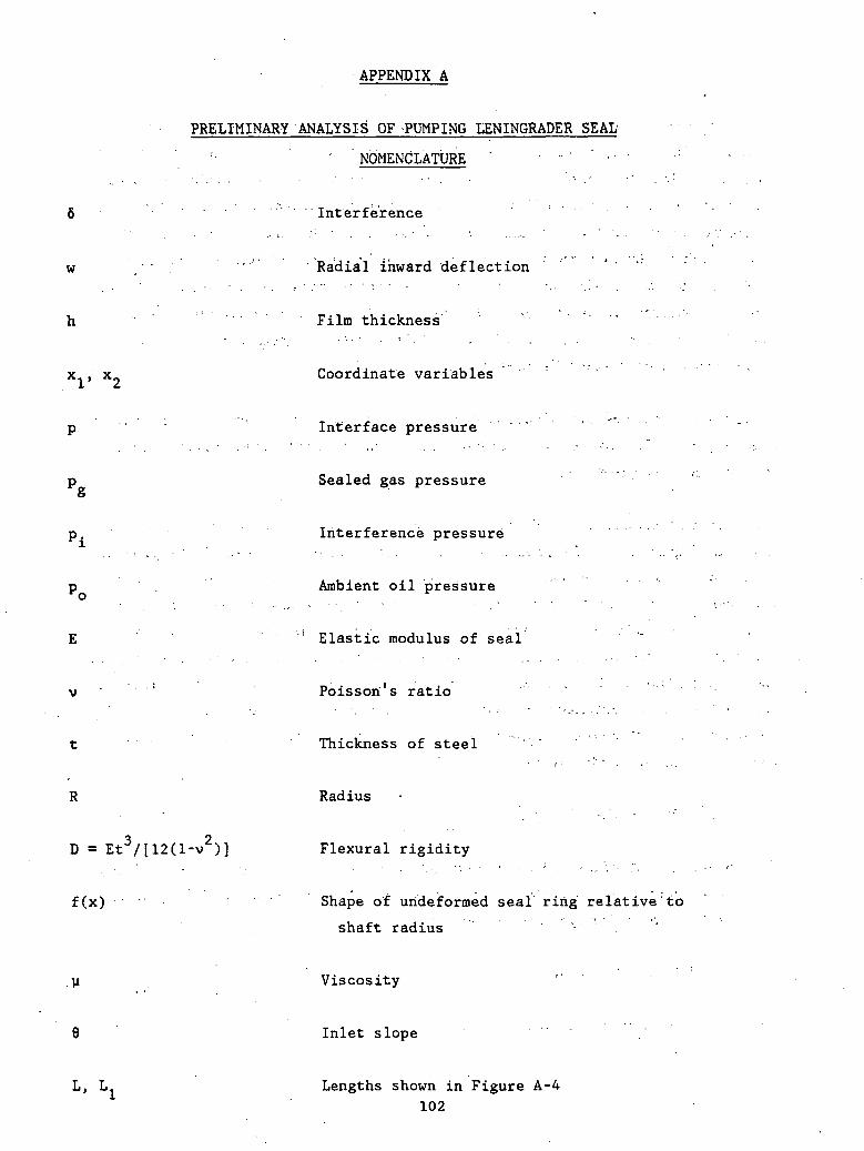
APPENDIX A
PRELIMINARY ANALYSIS OF -PUMPING LENINGRADER SEAL
'• " NOMENCLATURE ' " ' • •
6 • • - • • . interference
w / ' • • - . - " Radial inward deflection
h ' Film thickness
1, x9 Coordinate variables
Interface pressure
p Sealed gas pressureO
p. Interference pressure
p . Ambient oil pressure
E '' Elastic modulus of seal
v : Poisson's ratio
t Thickness of steel
R Radius
D = Et3/[12(l-v2)] Flexural rigidity
f(x) Shape of urideformed seal ring relative'to
shaft radius
V Viscosity
8 Inlet slope
L, L- Lengths shown in Figure A-4
102

Figure A-l is a schematic of a pumping Leningrader seal cross section mounted on
a shaft. The seal, which is preloaded against the shaft with an interference
fit, is loaded by a backup spring and by high-pressure gas, which acts behind
the seal and is separated from the oil by the static sealing land. The long,
chamfered inlet region provides the pumping action in that it forms a gradual
inlet which tends to trap or to provide a preferred direction for flow when the
shaft moves toward the cooling supply. (This is referred to as the forward
stroke.) During the backstroke, the seal (as drawn in Figure A-l) tends to rub
and wipe oil away. Thus, any oil that leaks toward the high-pressure gas tends
to be pumped back toward the cooling oil reservoir.
Figure A-2 shows the actual dimensions of the seal used in an automotive Stir-
ling engine. The dotted line denotes the geometry used in the initial modeling
of the seal discussed below.
A preliminary model has been developed for a seal with a constant thickness as
shown in Figure A-3. The pressure profile drawn under the seal is the pressure
anticipated to occur between the seal and the shaft during the forward stroke.
The pressure on the far left corresponds to the high-pressure gas, and the pres-
sure on the right represents the oil pressure. The constant pressure, p.,
denotes the compressive radial stress associated with the interference fit of
the ring on the shaft. The gas pressure is assumed to act along the outside of
the seal with an imaginary secondary seal separating the gas from the oil. The
deformation of the seal is assumed to be governed by the elasticity equations
for a thin axisymmetric cylindrical shell.
D(d4w/dx4) + (Et/R2)w = -(p - p ) (A-l)O
The geometric variables and coordinate system are shown in Figure A-4; w denotes
the inward radial deflection, E denotes the elastic.modulus of the seal, and D
denotes the flexural rigidity defined as:
D = Et3/[12(l - v2)]
where v is Poissons ratio for the seal.
103

IInlet Region
High-Pressure Gas
StaticSealing Land
Coo ling Oil
Fig. A-l Pumping Leningrader Seal
104

15.75 mm nominal
41.85 + 0.05 mm
15.6 mm
4> 18.0 mm
<{> 22. 0 mm
20.0 mm
18.0 mm
13.0 mm
3.0 mm
« v »
Fig. A-2 Seal Geometry for Automotive Stirling Engine Application
105
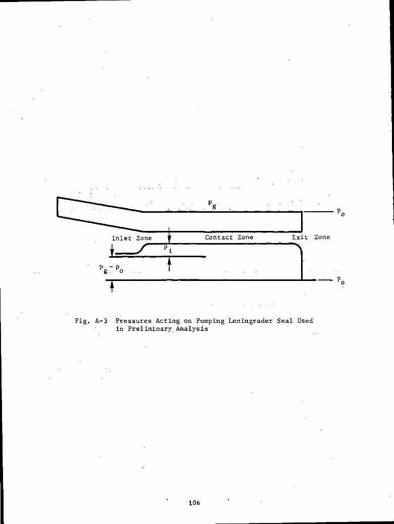
g . ,
± Contact Zone Exit Zone
p»- t
T
Fig. A-3 Pressures Acting on Pumping Leningrader Seal Usedin Preliminary Analysis
106

Underformed Seal
x = -L
Rod
JO IV
Fig. A-4 Schematic of Geometry Used in the Analysis
107

The quantity, p, enotes the pressure in the interface between the shaft and the
seal which will be determined by the Reynolds Equation for axisymmetric
steady-state motion during the forward stroke given by:
dp/dx = 6yU [(h - h*)/h3] . . . (A-2)
where h is the local hydrodynamic film thickness, y is the viscosity of the oil,
U is the average velocity during the forward stroke, and h* is a constant of
integration to be determined from the boundary conditions.
The film thickness h is related to the elastic deflection w by:
h = f(x) - w (A-3)
where f(x) is the radius of the undeformed seal relative to the shaft radius.
For the model depicted in Figure A-4, f (x) is given by:
0 < x < L
(A-4)
< x < 0
The boundary conditions on the elasticity equation come from the requirement
that both ends of the seal are free (forces and moments are zero at each end of
the seal). The boundary conditions on the Reynolds equation comes from the
requirements that the hydrodynamic pressures equal the prescribed gas pressure
at the high-pressure side and the prescribed oil pressure on the low-pressure
side. These may be written as:
'* ", v;.
d2w/dx2 = d3w/dx3 = 0 at x = -L and x = L (A-5)
p = p at x = -L. (A-6)
p = po at x = L (A-7)
Equations (A-l, through (A-7) represent a fifth-order nonlinear system corre-
sponding to the mo'el under consideration.
108

A number of approximations that are characteristic of elastohydrodynamic lubri-
cation may be introduced. These are based largely on the fact that the hydrody-
namic film thickness, h, will be small compared with the interference fit, 6.
The elastohydrodynamic behavior may be characterized by three zones:
• an inlet zone where the film develops ,
• a contact zone where the film thickness is nearly constant
• an exit zone where the pressure drops to ambient.
This type of behavior has been seen in many other types of elastohydrodynamic
lubrication, e.g., Hertzian contacts in rolling element bearings, elastomeric
bearings and foil bearings.
A.I Contact Zone Solution
The contact zone is the region extending from x = 0 to the start of the exit zone
which will be localized near x = L. In that region, from Equation (A-4) , f(x) =
-6 and from Equation (A-3), w = - 6 - h, which may be approximated by w = 5 since
|h/6| « 1. With w being constant, the left-hand terra in Equation (A-l) will)
vanish; hence the relationship
2p - p - p. = (Et5)/R , contact zone pressure (A-8)
Since p as determined in Equation (A-8) is constant in the contact zone, the
left-hand hand term in Equation (A-2) will vanish and the result will be h = h*,
constant (contact zone film thickness).
Equation (A-8) is essentially the dry contact pressure resulting from the inter-
ference fit. The dry contact profile would also contain a radial shear load at
the sharp corner at x = 0. With a small amount of wear, however, this corner
will be rounded, thus alleviating the radial shear load without radically
affecting the inlet film shape. Equation (A-8) will then be assumed to prevail
throughout the contact zone with the value of h* to be determined by matching
the pressure obtained from the solution to the equations for the inlet zone.
109

A.2 Inlet Zone Solution
In order to match the solution in the inlet zone with the contact zone solution,
the pressure and flow must be continuous at x = 0. This results in the
constraint
P = P +P iatx = 0 (A-9)
and ' • • • •
dp/dx = 0 at x = 0
which is equivalent to
h = h* at x = 0 (A-10)
For values of 8 'of the order of a few degrees or more, the pressure will vary
from its limiting values of p + p . at x = 0 to p over a relatively smallo •*• g
portion of the inlet zone as sketched in Figure A-3. If the shape of the inlet
zone is assumed to be unaffected by the pressure distribution in the region, the
film thickness relationship is
h = h* - 9x , x < 0
The stretched variable £ = - 8x/h* may now be introduced into Equation (A-2) to
obtain
dp/d? = -6u.UoC;/[9h*(l -I- O] ' --' (A-ll)
with the constraints - . .
= 0
and p = p at £ = 1 8/h* (A-13)
110
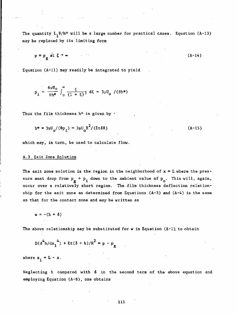
The quantity L..6/h* will be a large number for practical cases. Equation (A-13)
may be replaced by its limiting form
p = Pg at $ - » . - • • • • (A-14)
Equation (A-ll) may readily be integrated to yield
6yU0 oPi ~ 6h* '<.
Thus the film thickness h* is given by -
h* = 3vUo/(9Pi) = 3uUoR2/(Et68) (A-15)
which may, in turn, be used to calculate flow.
A.3 Exit Zone Solution
The exit zone solution is the region in the neighborhood of x = L where the pres-
sure must drop from p + p. down to the ambient value of p . This will, again,
occur over a relatively short region. The .film thickness deflection relation-
ship for the exit zone as determined from Equations (A-3) and (A-4) is the same
as that for the contact zone and may be written as
w = -(h + 6)
The above relationship may be substituted for w in Equation (A-l), to obtain
DCdSi/dXj4) + Et(6 + h)/R2 = p - p
where x. = L - x.
Neglecting h compared with 6 in the second term of the above equation and
employing Equation (A-8), one obtains
111
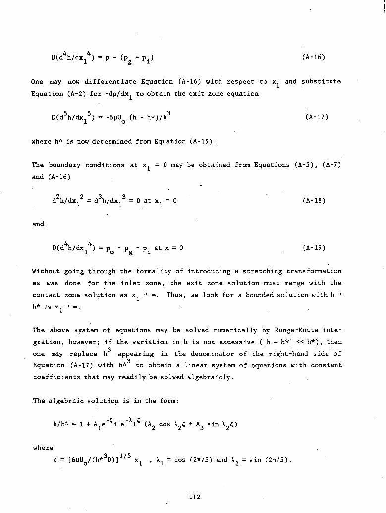
) = p - (pg + pi) (A- 16)
One may now differentiate Equation (A-16) with respect to x and substitute
Equation (A-2) for -dp/dx. to obtain the exit zone equation
D(d5h/dx,5) = -6uU (h - h*)/h3 (A-17)1 o
where h* is now determined from Equation (A-15).
The boundary conditions at x. =0 may be obtained from Equations (A-5), (A-7)
and (A-16)
= d3h/dx13 = 0 at x1 = 0 (A- 18)
and
j) = pQ - p - pL at x = 0 (A-19)
Without going through the formality of introducing a stretching transformation
as was done for the inlet zone, the exit zone solution must merge with the
contact zone solution as x1 -*• «. Thus, we look for a bounded solution with h -*•
h* as x- •*«»..
The above system of equations may be solved numerically by Runge-Kutta inte-
gration, however; if the variation in h is not excessive (|h = h*| « h*) , then3
one may replace h appearing in the denominator of the right-hand side of3
Equation (A-17) with h* to obtain a linear system of equations with constant
coefficients that may readily be solved algebraicly.
The algebraic solution is in the form:
h/h* = 1 + A"^ e"Xl? (A cos \ + A sin \~)
where
= [6uUQ/(h*3D)]1/5 xl , \1 = cos (2TT/5)
and X2 = sin (2lT/5)-
112
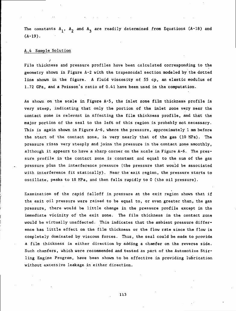
The constants A , A« and A_ are readily determined from Equations (A-18) and
(A-19).
A.4 Sample Solution
,1Film thickness and pressure profiles have been calculated corresponding to the
geometry shown in Figure A-2 with the trapezoidal section modeled by the dotted
line shown in the figure. A fluid viscosity of 55 cp, an elastic modulus of
1.72 GPa, and a Poisson's ratio of 0.41 have been used in the computation.
As shown on the scale in Figure A-5, the inlet zone film thickness profile is
very steep, indicating that only the portion of the inlet zone very near the
contact zone is relevant in affecting the film thickness profile, and that the
major portion of the seal to the left of this region is probably not necessary.
This is again shown in Figure A-6, where the pressure, approximately 1 mm before
the start of the contact zone, is very nearly that of the gas (10 MPa). The
pressure rises very steeply and joins the pressure in the contact zone smoothly,
although it appears to have a sharp corner on the scale in Figure A-6. The pres-
sure profile in the contact zone is constant and equal to the sum of the gas
pressure plus the interference pressure (the pressure that would be associated
with interference fit statically). Near the exit region, the pressure starts to
oscillate, peaks to 18 MPa, and then falls rapidly to 0 (the oil pressure).
Examination of the rapid falloff in pressure at the exit region shows that if
the exit oil pressure were raised to be equal to, or even greater than, the gas
pressure, there would be little change in the pressure profile except in the
immediate vicinity of the exit zone. The film thickness in the contact zone
would be virtually unaffected. This indicates that the ambient pressure differ-
ence has little effect on the film thickness or the flow rate since the flow is
completely dominated by viscous forces. Thus, the seal could be made to provide
a film thickness in either direction by adding a chamfer on the reverse side.
Such chamfers, which were recommended and tested as part of the Automotive Stir-
ling Engine Program, have been shown to be effective in providing lubrication
without excessive leakage in either direction.
113

in
*T
Z Z
Z
"* 10
X o
— i
o in
o z 2
•
-H
Z
C
<S> 1
C-«
1
0
UJ
• «
Z
Z
cu
<•
<
UJ
Co
"->
a
•
• a uj
io
u. u
it—
cc. ^
c._J
U.
UJ O
U
t. f.
»- a
: uU
J I Z
I- C
•
o
•u. a
c •
L mi
»> a
•» O
i </>
3
h-
J U
JJ
_1
. Z
0
C
/\
VJ^
c
CM
O
5 1
Ofsi
Oooa.
oor
cacaa)CHE00
(SN
OdO
IW)
SS
3N)O
IH1 H
lld
114
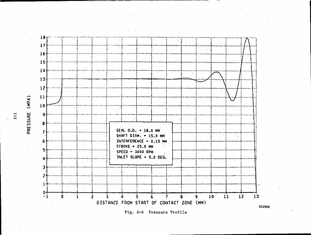
....•*. ...•
•••
tooU
la
o
in o
x
X-
• -.
X 0
.00
I
CC
i • o
>r> o
ui
i z
C
M o o
.• <
u
i n
oa
•-•' cc i
-i• a
ui • i «/*
o
u. u
i»-
oc ^ o
»—_i u. u* o
ui ui«
.«t
>- er tu _j
ui x z i- a. z
—
....—
__
-c\j
- • o
LUOOoI—cc
o£toCO(U
JsZ
00
O
1-1
cc f**
*o
in
CM
"' — <
o a»
oo«o
-^
csi
115
APPENDIX B
COMPUTER PROGRAM "RING"
The computer program RING which has been used throughout the report is listed
herein. It is written in IBM FORTRAN 77 (VS), and uses an IMSL subroutine
ZSCNT. A FORTRAN IV Listing of ZSCNT and its subroutines is also included for
completeness. The FORTRAN listings are preceded with an input description, an
output description, and sample inputs and outputs.
116
B.I INPUT DESCRIPTION
All input variables are on a namelist (NAMELIST/INPUTS/). Symbols in the left
column denote the FORTRAN names of the namelist variables. Symbols appearing
on the right correspond to the nomenclature given at the beginning of the
report.
Input Variable Definitions
STRING A character string of up to 60 characters to identify job
IDIM Type of input
0 - Dimensionless (default value)
1 - Dimensional (any consistent set of units)
Dimensional Inputs (used only if IDIM = 1)
NI Frequency (Hz), f
SI Stroke (L), s
CI Clearance (L), c
ELI Bearing length (L), L
EL1I Length of nonbearing portion of ring (L), LI
El Length over which po acts (L), e
RI Shaft radius (L), R
TI Ring thickness (L), t
ClI Initial taper, 6 (defaults to 0)
POI Preload pressure (F/L2), p0
PFI Reservoir pressure (F/L ), pf
RMUI Lubricant viscosity (FT/L2), U
EMOD Ring modulus of elasticity (F/L2), E
POIS Ring Poisson's Ratio, V
Nondimensional Inputs
AL a
BET 8
EPS £
117

ELI LI
Cl 6L/C (defaults to 0) .
PO Po
PF Pf
ELOS L/s for starvation calculation (defaults to 0)
NDX A vector of length 3 containing number of increments for
Runge-Kutta integration
NDX(l) = Number of increments i n l - e < 5 < ! (defaults to 40)
NDX(2) = Number of increments i n O < 5 < l - e (defaults to 25)
NDX(3) = Number of increments in -Li < £ < 0 (defaults to 25)
NDP A vector of length (3) containing number of points at which
pressures etc. are saved for printout. NDX(i) should be inte-
gral multiples of NDP(i). (Defaults are NDP(l) = 10, NDP(2) =
25, NDP(3) = 25.)
ICAV Flag calculation of cavitation (backstroke)
0 - No cavitation (negative pressures allowed)
2 - Cavitation included, no negative pressures (default value)
IPR Print Flag
0 - Short output (default value)
1 - Longer output (print pressure profile etc.)
NMAX Maximum iterations for secant method solution (default is 10)
NSIG Number of significant digits in accuracy of solution using
secant method (default is 4)
XF A vector of length (2) containing initial guesses for forward
stroke secant solution
XF(1) = Initial guess for h at £ = 1
XF(2) = Initial guess for dh/dC at
118
If XF(1) and XF(2) are both set equal to 0, the program will
attempt to find its own initial guesses. In subsequent runs,
values determined from the previous run are used unless
explicitly specified.
XB
for XF.
A vector length (2) containing initial guesses for h and dh/d5
for reverse stroke secant solution. Same rules apply to XB as
119
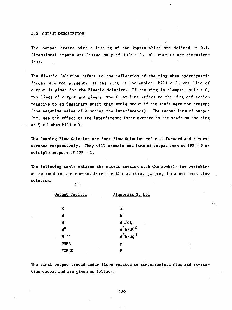
B.2 OUTPUT DESCRIPTION
The output starts with a listing of the inputs which are defined in D.I.
Dimensional inputs are listed only if IDIM - 1. All outputs are dimension-
less.
The Elastic Solution refers to the deflection of the ring when hydrodynamic
forces are not present. If the ring is unc Lamp led, h(l) > 0, one line of
output is given for the Elastic Solution. If the ring is clamped, h(l) < 0,
two lines of output are given. The first line refers to the ring deflection
relative to an imaginary shaft that would occur if the shaft were not present
(the negative value of h noting the interference). The second line of output
includes the effect of the interference force exerted by the shaft on the ring
at 5 = 1 when h(l) = 0.
Thw Pumping Flow Solution and Back Flow Solution refer to forward and reverse
strokes respectively. They will contain one line of output each at IPR = 0 or
multiple outputs if IPR = 1.
The following table relates the output caption with the symbols for variables
as defined in the nomenclature for the elastic, pumping flow and back flow
solution.' ' !''•
Output Caption Algebraic Symbol
x 5H h
H1
H"
H1" d3h/d$3
PRES p
FORCE F
The final output listed under flows relates to dimensionless flow and cavita
tion output and are given as follows:
120
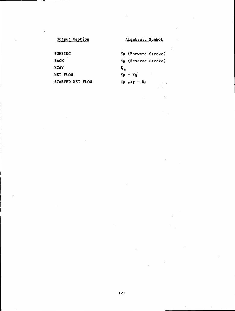
Output Caption Algebraic Symbol
PUMPING Kp (Forward Stroke)
BACK KR (Reverse Stroke)
XCAV 5C
NET FLOW Kp - KR
STARVED NET FLOW Kp eff - KR
121
B.3 SAMPLE INPUT AND OUTPUT
The sample input and output contained herein correspond to three solutions for
a babbitt pumping ring with loading pressures, po, of 3.45, 5.17 and 6.89 MPa
(500, 750 and 1000 psi). A full printout (IPR = 1) was requested at po = 3.45
MPa (500 psi). It should be noted that the ring is predicted to be clamped
during the backstroke at p0 - 6.89 MPa (1000 psi).
122
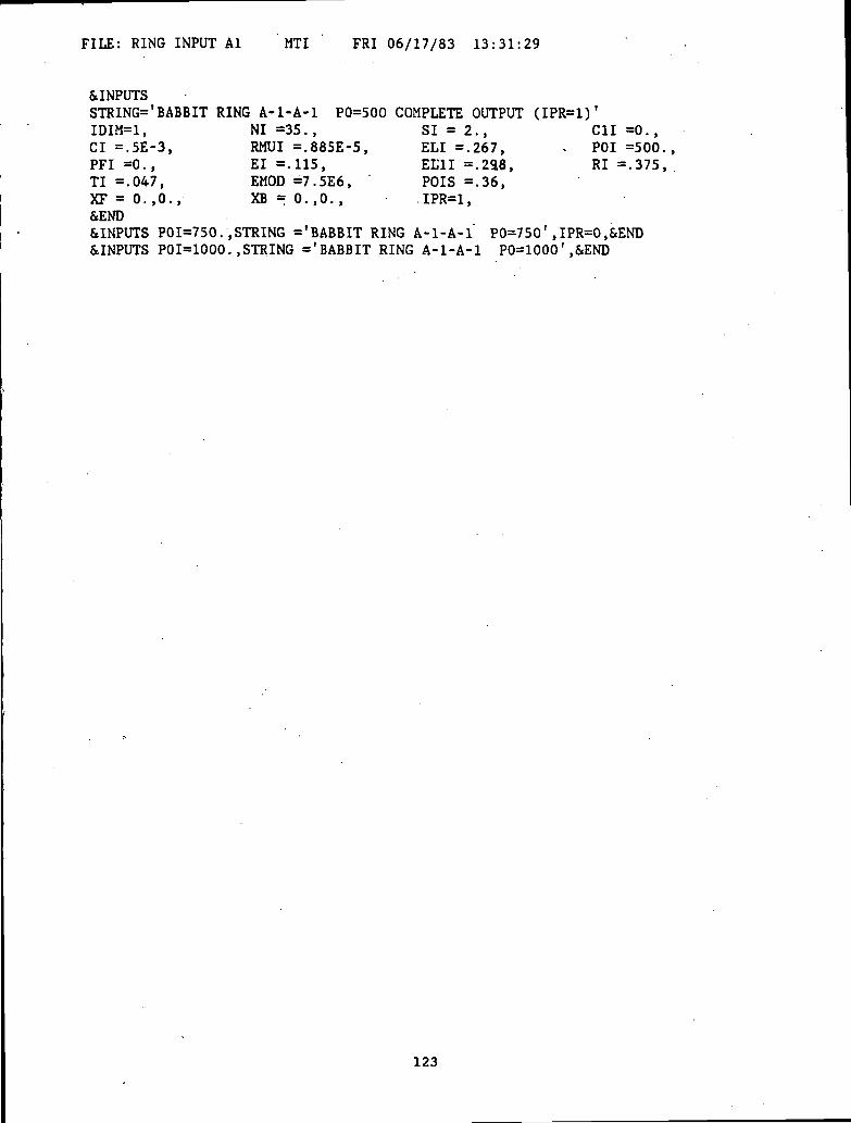
FILE: RING INPUT Al MTI FRI 06/17/83 13:31:29
&INPUTSSTRING='BABBIT RING A-l-A-1 P0=500 COMPLETE OUTPUT (IPR=1)'IDIM=1, NI =35., SI = 2., C1I =0.,CI =.5E-3, RMUI =.885E-5, ELI =.267, - POI =500.,PFI =0., El =.115, EL1I =.238, RI=.375,TI =.047, EMOD =7.5E6, " POIS =.36,XF=0.,0., XB=0.,0., .IPR=1,&END&INPUTS PO1=750.,STRING ='BABBIT RING A-l-A-l" P0=750*,IPR=0,&END&INPUTS PO1=1000..STRING ='BABBIT RING A-l-A-1 P0=1000',&END
123

* PUMPING RING ANALYSIS PROGRAM *
INPUTS
STRING = BABBIT RING A-l-A-1
DIMENSIONAL INPUTS
P0=500 COMPLETE OUTPUT (IPR=1)
ELIElC1ISIRMUI
POIEMOD
0.267000000+00; EL1I0.115000000+00; CI0.000000000+00; TI0.200000000+01; RI0.88500000D-05; NI
= 0.298000000+00;= 0.50000000D-03;= 0.47000000D-01;= 0.375000000+00;= 0.35000000D+02;
0.500000000+03; PFI = 0.000000000+00;0.750000000+07; POIS = 0.360000000+00;
'(it'fc&ic'itic'tf'tcitit'ic'ic'&ic'ic'ft'fc'&'tdf'fr'i
IDIMALEPSELISTARV
NDXNDP
i;0.660856540-02; BET0.430711610+00; PO0.111610490+01; PF0.320419660+00; Cl
= 0.715354540+01;= 0.629761630-01;= 0.000000000+00;= 0.000000000+00;
40,10,
25,25,
25;25;
NMAX = 10; NSIG =IPR 1; ICAV =XF = 0.000000+00XB = 0.000000+00
4;2;0.000000+000.000000+00
'f dt'rf'fe'tt'rdC' f'fC'fCfrfC'if'iff'rtif'frtf'if
*-»*- -iHr*-iHr*«**
OUTPUTS•»•&••* ft ft ft ft ft ft ft ft'ft-fr ft fr » A * ft ft ft ****
* ELASTIC SOLUTION *
X H H1
1.0000 0.48845 -0.67281H"
0.00000H'"
0.00000PRES
0.00000FORCE0.00000
* PUMPING FLOW SOLUTION *
1.00000.99140.97420.95690.9397.9225.9052
0.88800.87080.85360.83630.81910.8019
0,0,
H
0.818140.824130.836110.848090.860060.872010.883930.895820.907640.919400.931080.942650.95411
Hf
-0.69559-0.69558-0.69548-0.69510-0.69429-0.69294-0.69093-0.68819-0.68464-0.68022-0.67488-0.66859-0.66132
-0
H"
0.000000.001470.012540.033040.061490.096550.13710
182160.230920.282700.336950.393240.45126
H"1
0.000000.336450.931871.434181.854872046349334730199236908173
3.211613.320083,41339
PRES
0.000000.003750.010740.017090.022850.028050.032740.036950.040710.044050.047010.049600.05186
124

0.78460.76740.75020.73300.71.570.69850.68130.66400.64680.62960.61240.59510.57790.56930.55790.53510.51240.48960.46680.44400.42130.39850.37570.35300.33020.30740.28460.26190.23910.21630.19360.17080.14800.12520.10250.07970.05690.03420.0114-0.0000
X
1.00000.99140.97420.95690.93970.92250.90520.88800.87080.85360.8363
0.965430.976600.987610.998421.009031.019411.029541.039411.048991.058251.067191.075771.083961.087911.092971.102491.111201.119041.126001.132061.137211.141461.144811.147281.148911.149721.149751.149051.147661.145641.143031.139901.136301.132281.127911.123241.118331.113221.107981.10532
H
0.488450.494240.505840.517430.529020.540620.552230.563840.575460.587100.59875
-0.65304-0.64371-0.63333-0.62186-0.60927-0.59555-0.58066-0.56456-0.54720-0.52854-0.50853-0.48709-0.46415-0.45209-0.43555-0.40062-0.36370-0.32532-0.28598-0.24614-0.20622-0.16663-0.12772-0.08982-0.05323-0.018210.015000.046230.075290.102060.126430.148330.167720.184590.198940.210830.220340.227550.232620.23439
* BACK FLOW
H1
-0.67281-0.67281-0.67284-0.67292-0.67309-0.67338-0.67378-0.67431-0.67495-0.67570-0.67652
-0.51080-0.57175-0.63406-0.69781-0.76311-0.83016-0.89921-0.97058-1.04464-1.12178-1.20247-1.28718-1.37644-1.42295-1.48207-1.58150-1.65702-1.71003-1.74199-1.75435-1.74861-1.72623-1.68871-1.63751-1.57408-1.49988-1.41633-1.32484-1.22678-1.12353-1.01643-0.90681-0.79599-0.68524-0.57586-0.46912-0.36627-0.26857-0.17726-0.13439
SOLUTION *
H"
0.000000.000330.002790.007210.013070.019850.027030.034090.040500.045750.04931
3.497293.577093.657683.743543.838803.947194.072164.216794.383894.575984.795305.043825.323285.475084.912283.831322.811671.854970.962350.13448-0.62831-1.32603-1.95894-2.52748-3.03230-3.47412-3.85377-4.17212-4.43005-4.62844-4.76813-4.84992-4.87453-4.84260-4.75471-4.61129-4.41272-4.15924-3.85102-3.67640
H"1
0.00000-0.07580-0.20473-0.30344-0.37193-0.41019-0.41820-0.39595-0.34341-0.26055-0.14735
0.053800.055450.056820.057930.058810.059460.059900.060150.060210.060110.059840.059430.058870.058550.058070.056950.055640.054160.052520.050730.048810.046760.044610.042360.040010.037590.035090.032520.029890.027210.024480.021710.018900.016060.013190.010290.007370.004430.001480.00000
PRES
0.000000.000000.000000.000000.000000.000000.000000.000000.000000.000000.00000
125
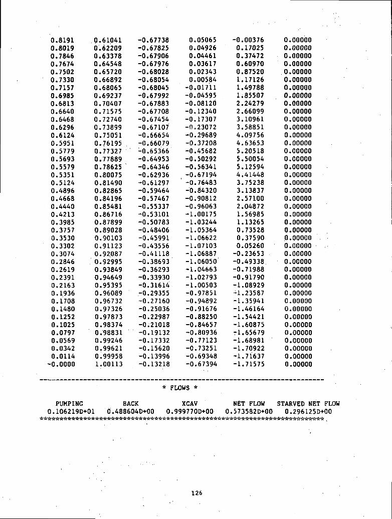
0.81910.80190.78460.76740.75020.73300.71570.69850.68130.66400.64680.62960.61240.59510.57790.56930.55790.53510.51240.48960.46680.44400.42130.39850.37570.35300.33020.30740.28460.26190.23910.21630.19360.17080.14800.12520.10250.07970.05690.03420.0114-0.0000
0.610410.622090.633780.645480.657200.668920.680650.692370.704070.715750.727400.738990.750510.761950.773270.778890.786250.800750.814900.828650.841960.854810.867160.878990.890280.901030.911230.920870.929950.938490.946490.953950.960890.967320.973260.978730.983740.988310.992460.996210.999581.00113
-0.67738-0.67825-0.67906-0.67976-0.68028-0.68054-0.68045-0.67992-0.67883-0.67708-0.67454-0.67107-0.66654-0.66079-0.65366-0.64953-0.64346-0.62936-0.61297-0.59464-0.57467-0.55337-0.53101-0.50783-0.48406-0.45991-0.43556-0.41118-0.38693-0.36293-0.33930-0.31614-0.29355-0.27160-0.25036-0.22987-0.21018-0.19132-0.17332-0.15620-0.13996-0.13218
0.050650.049260.044610.036170.023430.00584-0.01711-0.04595-0.08120-0.12340-0.17307-0. 23072-0.29689-0.37208-0.45682-0.50292-0.56341-0.67194
' -0.76483-0.84320-0.90812-0.96063-1.00175-1.03244-1.05364-1.06622-1.07103-1.06887-1.06050-1.04663-1.02793-1.00503-0.97851-0.94892-0.91676-0.88250-0.84657-0.80936-0.77123-0.73251-0.69348-0.67394
-0.003760.170250.374720.609700.875201.171261.497881.855072.242792.660993.109613.588514.097564.636535.205185.500545.125944.414483.752383.138372.571002.048721.569851.132650.735280.375900.05260-0.23653-0.49338-0.71988-0.91790-1.08929-1.23587-1.35941-1.46164-1.54421-1.60875-1.65679-1.68981-1.70922-1.71637-1.71575
0.000000.000000.000000.000000.000000.000000.000000.000000.000000.000000.000000.000000.000000.000000.000000.000000.000000.000000.000000.000000.000000.000000.000000.000000.000000.000000.000000.000000.000000.000000.000000.000000.000000.000000.000000.000000.000000.000000.000000.000000.000000.00000
* FLOWS *
PUMPING0.106219D+01
BACK XCAV NET FLOW STARVED NET FLOW0.488604D+00 0.999770D+00 0.573582D+00 0.296125D+00************
126

* PUMPING RING ANALYSIS PROGRAM *
INPUTS********** ft'A-A ft ft- *ftft**ft»*************************
STRING = BABBIT RING A-l-A-1 P0=750** ft ft A **** * ft******* *ft ** ft1* ft it U ft ft-*******************************************
DIMENSIONAL INPUTS
ELI = 0.267000000+00; EL1IEl = 0.115000000+00; CIC1I = 0.000000000+00; TISI = 0.200000000+01; RIRMUI = 0.885000000-05; NI
= 0.298000000+00;= 0.500000000-03;= 0.470000000-01;= 0.375000000+00;= 0.350000000+02;
POI = 0.750000000+03; PFI = 0.000000000+00;EMOD = 0.750000000+07; POIS = 0. 360000000+00;******* ft A fl"A"A-A ft**** ftA'AAft'ftftftftftAftftaAAftfe ft "*a** ft * A'************* ft ftftIDIM =1;
= 0.71535454D+01;= 0.94464244D-01;= O.OOOOOOOOD+00;= O.OOOOOOOOD+00;
ALEPSELI
= 0.66085654D-02; BET= 0.43071161D+00; PO= 0.11161049D+01; PF
STARV = 0.32041966D+00; Cl
NDXNDP =
NMAX =IPR =XFXB
40,10,
25, 25;25, 25;
10; NSIG =0; ICAV =0.81814D+000.48845D+00
4;2;-0.695590+00-0.672810+00
******** A ft A'A *** A ft Aft ft ****************************************************
OUTPUTS******************ftA*A*ft************************************************
H H1
* ELASTIC SOLUTION *
H1 PRES1.0000 0.23267 -1.00922 0.00000 0.00000 0.00000
* PUMPING FLOW SOLUTION *
X H H' H" H'"
1.0000 0.71873 -0.93560 0.00000 0.00000
FORCE0.00000
PRES
0.00000
* BACK FLOW SOLUTION *
X
1.0000
H
0.23267
H1
-1.00922
H"
0.00000
H'"
0.00000
PRES
0.00000
PUMPING0.100210D+01
BACK0.232747D+00
* FLOWS *
XCAV0.999927D+00
NET FLOW STARVED NET FLOW0.769350D+00 0. 3299150+00
127

* PUMPING RING ANALYSIS PROGRAM *
DIMENSIONAL INPUTS
INPUTS&&*$r&&&&&&&*!rit*it tt'rC'£?'{ff'ti'rff't?'tc'tt'f
STRING = BABBIT RING A-l-A-1 P0=1000-**-ft* ^
= 0.29800000D+00;= 0.50000000D-03;= 0.47000000D-01;= 0.37500000D+00;= 0.35000000D+02?
ELIElC1ISIRMUI
0.26700000D+00; EL1I0.11500000D+00; CIO.OOOOOOOOD+00; TI0.20000000D+01; RI0.88500000D-05; NI
POI = 0.10000000D+04; PFI = O.OOOOOOOOD+00;EMOD = 0.75000000D+07; POIS = 0.36000000D+00;ft^fraaaftafraa^ttfrfrftaftftttfrTt-frfrVH^^******^******^
IDIM - 1;AL
EPSELISTARV
NDXNDP
NMAXI PRXFXBJU •*••*• «fa«IU.J
= 0.66085654D-02; BET= 0.43071161D+00; PO= 0.11161049D+01; PF= 0.32041966D+00; Cl
= 40, 25, 25;10, 25, 25;
10; NSIG = 4;= 0; ICAV = 2;
0.71873D+00 -0.0.23267D+00 -0.
= 0.71535454D+01;= 0.12595233D+00;= O.OOOOOOOOD+00;= O.OOOOOOOOD+00;
93560D+0010092D+01•JfJ~*t+~t~J~J~*~A.J~ . ~f~ ~J~J-J. i~J.J*J.J~J*J~J~J~J.'J~ '~'J+Jft
*********************
OUTPUTSwxwwKwwwwwxwwwwww«w«ww«wwx«wwTrwwwwwwwwwwwwwwwwwwwwwwwwwTrw'KTr ixp-sr isfw-K'K>r>f'jr iic-x-5r-xp
* ELASTIC SOLUTION *
X1.00001.0000
H-0.02310
0.00000
H'-1.34562-1.28833
00
H".00000.00000
H"'0.00000
-0.7047900
PRES.00000.00000
FORCE0.000000.00065
* PUMPING FLOW SOLUTION *
X < H H' H" H"' PRES
1.0000 0.63082 -1.13187 0.00000 0.00000 0.00000
* BACK FLOW SOLUTION *
X1.0000
H0.00000
H'-1.28833
H"0.00000
H"'-0.70479
PRES0.00000
FORCE0.00065
PUMPING0.929129D+00
* FLOWS *
BACK XCAV NET FLOW STARVED NET FLOWO.OOOOOOD+00 0.100000D+01 0.929129D+00 0.333707D+00
128

B.4 FORTRAN LISTING
FILE: RING FORTRAN L4 MTI MON 01/20/86 14:39:26 PAGE 1 OF 38
c§ vs
CNOTE:CCCCCCCCCCCCCCCCCCCCCCCCCCCCCCCCCCCCCCCCCCCCCCCCCCC
PROGRAM RING
XLAM=.739*ELOS**-.585 IS NOW BUILT INTO PROGRAM
FUNCTION - PUMPING RING ANALYSIS PROGRAM
RESTRICTIONS - STEADY-STATE ANALYSIS ONLY
REMARKS - VS FORTRAN (FORTRAN 77)IMPLICIT DOUBLE PRECISION REAL*8
EXTERNAL REFERENCES -FORTRAN ROUTINES
DATANIMSL ROUTINES
ZSCNT ; SOLVES THE SYSTEM OF NON-LINEAREQUATIONS ; LISTING PROVIDED HEREIN BYPERMISSION OF IMSL.
USER ROUTINESAIN ; COMPUTE INVERSE OF 2X2 MATRIXAMU ; MULTIPLY 2 2X2 MATRICESCALCD ; CALCULATE ELASTIC INFLUENCE
COEFFICIENTS C,DCHECK ; FOR MULTIPLE RUNS CHECK INPUTS
FOR RECALCULATION OF C,DCONST ; CALCULATE SLIDER BEARING PRESSURE
CONSTANTSCONST2 ; SAME AS ABOVEDFN1 ; DERIVATIVE FUNCTION USED BY RUKDFN2 ; " " " " "DFN3 ; " " " " "ELAS ; DETERMINE ELASTIC SOLUTION
(NO HYDRODYNAMICS)
RIN00010RIN00020-RIN00030RIN00040RINOOOSORIN00060RIN00070RINOOOSORIN00090RIN00100RIN00110RIN00120RIN00130RIN00140RIN00150RIN00160RIN00170RIN00180
. RIN00190RIN00200RIN00210RIN00220RIN00230RIN00240RIN00250RIN00260RIN00270RIN00280RIN00290RIN00300RIN00310RIN00320RIN00330RIN00340RIN00350
ERRMSG ; PRINT ERROR MESSAGE IF *ZSCNT* NOTRIN00360CONVERGED
EVAL ; DEFINE NON-LINEAR SYSTEM IN H AND HTO BE SOLVED BY *ZSCNT*
P ? PRESSURE FUNCTIONPRT ; CONVERT FROM W TO H AND PRINTPRTOUT ; PRINT OUT RESULTSRUK ; RUNGE-KUTTA
INPUT/OUTPUT:UNIT DESCRIPTION4 TERMINAL I/O5 INPUT FILE IN NAMELIST FORMAT6 OUTPUT FILE
INPUT VARIABLE DEFINITIONS* NOTE : (D) INDICATES VARIABLE HAS A DEFAULT VALUE
NAME DESCRIPTIONNAMELIST /INPUTS/
RIN00370'RIN00380RIN00390RIN00400RIN00410RIN00420RIN00430RIN00440RIN00450RIN00460RIN00470RIN00480RIN00490RIN00500RIN00510RINOOS20RIN00530RIN00540RIN00550
129

FILE: RING FORTRAN L4 MTI MON 01/20/86 14:39:26 PAGE 2 OF 38
ccccccccccccccccccccccccccccccccccccGccccccccccccccc
c
STRINGIDIM (D)
CHARACTER STRING TO IDENTIFY JOB (MAX. 60 CHARS.)TYPE OF INPUT0 - DIMENSIONLESS1 - DIMENSIONAL (ANY CONSISTENT SET OF UNITS)
DIMENSIONAL INPUTS (NOTE: UO=2.*NI*SI)
NISICI
. . ELIEL1IElRITIC1I (D)POIPFIRMUIEMOOPOIS
FREQUENCY (HZ)STROKE (L)CLEARANCE (L)BEARING LENGTH (L)LENGTH OF NON-BEARING PORTION OF RING (L)LENGTH FROM END OF BEARING PRELOADED WITH POI (L)RING RADIUS (L)RING THICKNESS (L) .BEARING SLOPEPRELOAD PRESSURE (F/L**2)RESERVOIR PRESSURE (F/L**2)LUBRICANT VISCOSITY (FT/L**2)RING MODULUS OF ELASTICITY (F/L**2)RING POISSON'S RATIO
NON-DIMENSIONAL INPUTS
ALBETEPSELIELOS (D)XLAM (D)
- Cl (D)POPF
NDX(3) (D)NDP(3) (D)
ICAV (D)
IPR (D)
NMAX (D)NSIG (D)
XF(2)XB(2)
(TI*RI)**2/(12*ELI**4*(1.-POIS)**2))(T*RMUI*UO*RI**2*ELI)/(CI**3*TI*EMOD)LENGTH FROM END OF PRELOAD PO (El /ELI)LENGTH OF NON-BEARING PORTION OF RING (EL1I/ELI)
RIN00560RIN00570RIN00580RIN00590RIN00600RIN00610RIN00620RIN00630RIN00640RIN00650RIN00660RIN00670RIN00680RIN00690RIN00700RIN00710RIN00720RIN00730RIN00740RIN00750RIN00760RIN00770RIN00780RIN00790RIN00800RIN00810RIN00820RIN00830RIN00840
L/S LAND TO STROKE RATIO FOR STARVATION CALCULATIONRIN00850MULTIPLIES ELOS FOR INCREASED STARVATIONSLOPE OF BEARINGPRELOAD PRESSURE (CI**2/(6*RMUI*UO*ELI))*POIRESERVOIR PRESSURE (CI**2/(6*RMUI*UO*ELI))*PFI
DELTA X INCREMENTS FOR RUKti ii ii it it
FLAG FOR CALCULATION OF CAVITATION (BACK STROKE)0 - NO CAVITATION (NEC. PRESSURES ALLOWED)1 - CAVITATION (NO NEC. PRESSURES)2 - FIND ITS OWN SOLUTIONPRINT FLAG0 - SHORT OUTPUT1 - LONGER OUTPUT (PRINT PRESSURE PROFILE)
MAX. ITERATIONS FOR *ZSCNT*NO. OF SIGNIFICANT DIGITS IN ACCURACYOF SOLUTION USING *ZSCNT*INITIAL GUESS FOR H AND H' FOR FORWARD STROKEINITIAL GUESS FOR H AND H1 FOR BACKWARD STROKE
IMPLICIT REAL*8 (A-H,0-Z)
RIN00860RIN00870RIN00880RIN00890RIN00900RIN00910RIN00920RIN00930RIN00940RIN00950RIN00960RIN00970RIN00980RIN00990RIN01000RIN01010RIN01020RIN01030RIN01040RIN01050RIN01060RIN01070
RIN01090RIN01100
130
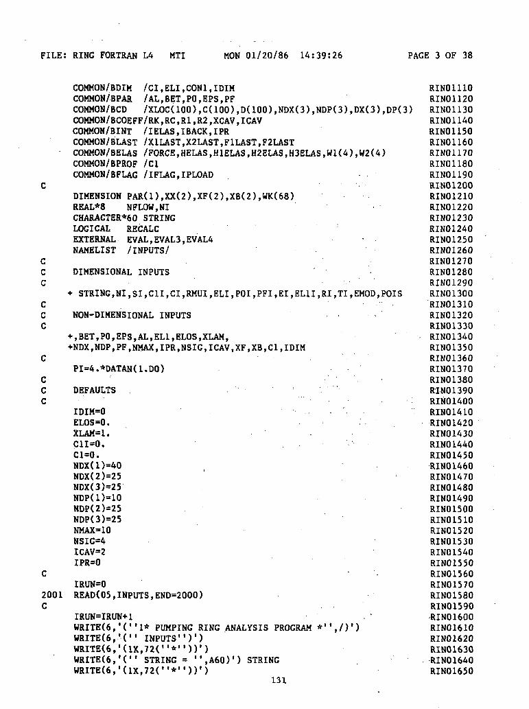
FILE: RING FORTRAN L4 MTI MON 01/20/86 14:39:26 PAGE 3 OF 38
CCC
CCC
CCC
2001C
COMMON/BDIM /CI,ELI,CON1,IDIMCOMMON/BPAR /AL,BET,PO,EPS,PFCOMMON/BCD /XLOC(IOO),C(100),D(100),NDX(3),NDP(3),DX(3),DP(3)COMMON/BCOEFF/RK,RC,R1,R2,XCAV,ICAVCOMMON/BINT /IELAS,IBACK,IPRCOMMON/BLAST /X1LAST,X2LAST,F1LAST,F2LASTCOMMON/BELAS /FORCE,HELAS,H1ELAS,H2ELAS,H3ELAS,W1(4),W2(4)COMMON/BPROF /ClCOMMON/BFLAG /IFLAG,IPLOAD
DIMENSION PAR(1),XX(2),XF(2),XB(2),WK(68)REAL*8 NFLOW,NICHARACTER*60 STRINGLOGICAL RECALCEXTERNAL EVAL,EVAL3,EVAL4 •NAMELIST /INPUTS/
DIMENSIONAL INPUTS '
•«• STRING, NI, SI, C1I,CI,RMUI, ELI, POI,PFI, El, EL1I,RI,TI,EMOD,POIS
NON-DIMENSIONAL INPUTS
•••, BET, PO, EPS, AL, ELI, ELOS ,XLAM,+NDX,NDP,PF,NMAX,IPR,NSIG,ICAV,XF,XB,C1,IDIM
PI=4.*DATAN(1.DO)
DEFAULTS
IDIM=0 • - . . ' . - . .ELOS=0.XLAM=1.C1I=0.Cl=0.NDX(1)=40NDX(2)=25NDX(3)=25NDP(1)=10NDP(2)=25NDP(3)=25NMAX=10NSIG=4ICAV=2IPR=0
IRUN=0READ(05,INPUTS,END=2000)
IRUN=IRUN+1WRITE(6,'("1* PUMPING RING ANALYSIS PROGRAM *",/)')WRITE(6,'(" INPUTS")')WRITE(6,'(1X,72("*"))')WRITE(6,'(" STRING = ",A60)') STRINGWRITE(6,'(1X,72("*"))1)
131
RING 1110RIN01120RIN01130RIN01140RIN01150RIN01160RIN01170RIN01180RIN01190RIN01200RIN01210RIN01220RIN01230RIN01240RIN01250RIN01260RIN01270RIN01280RIN01290RIN01300RIN01310RIN01320RIN01330RING1340RIN01350RIN01360RIN01370RING1380RIN01390RIN01400RIN01410RIN01420RIN01430RIN01440RIN01450RIN01460RIN01470RING1480RIN01490RIN01SOORIN01510RIN01520RIN01530RIN01540RIN01550RIN01560RIN01570RIN01580RIN01590RING1600RIN01610RIN01620RIN01630RIN01640RIN01650
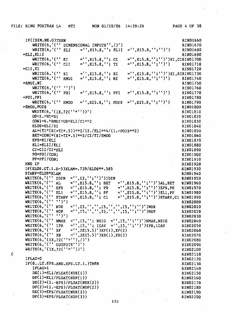
FILE: RING FORTRAN L4 MTI MON 01/20/86 14:39:26 PAGE 4 OF 38
IF(IDIM.NE.O)THENWRITE(6,'(" DIMENSIONAL INPUTS",/)')WRITE(6,'(" ELI =",E15.8,"; EL1I
+ELI,EL1IWRITE(6,'(" El ="WRITE(6,'(" C1I ="
SI
= ",E15.8,"• ' '
,E15.8,
CITI
RINI
= ",E15.8,"= ",E15.8,"
_l 1 rfie a I I— ,Cilj • 0 ,_l 1 CM e a II— ,£•! J .0 ,
= ",E15.8,"; PFI = ",E15.8,"
3,"; POIS = ",E15.8,' '
WRITE(6,'(''WRITE(6,'(" RMUI
+RMUI.NIWRITE(6,'(" ")'WRITE(6,'(" POI
+POI,PFIWRITE(6,'(" EMOD
+EMOD,POISWRITE(6,'(1X,72("*"))')UO=2.*NI*SICON1=6.*RMUI*UO*ELI/CI**2ELOS=ELI/SIAL=(TI*(RI+TI*.5))**2/12./ELI**4/(1 .-POIS**2)BET=CON1*(RI+TI*.5)**2/CI/TI/EMODEPS=EI/ELIEL1=EL1I/ELIC1=C1I/CI*ELIPO=POI/CON1PF=PFI/CON1
END IFIF(ELOS.GT.1.D-5)XLAM=.739/ELOS**.585
RIN01660RIN01670
, / , RIN01680RIN01690
;")')EI,CIRIN01700';")') RIN01710
RIN01720)')SI,RIRIN01730)') RIN01740
RIN01750RIN01760
)') RIN01770RIN01780
)') RIN01790RIN01800RIN01810RIN01820RIN01830RIN01840RIN01850RIN01860RIN01870RIN01880RIN01890RIN01900RIN01910RIN01920RIN01930
, i i
. i i>
t« A n*.~\ T *^ «_iv^ fc* f\ <U u I
WRITE(6,'(" IDIM =",12,"; ')')IDIMWRITE(6,'(" AL =",E15.8, ' ; BET =",E15.8,'WRITE(6,'(" EPS =",E15.8, '; PO =",E15.8,'WRITE(6,'(" ELI =",E15.8, '; PF =",E15.8,'WRITE(6,'(" STARV =",E15.8, '; Cl =",E15.8,'WRITE(6,'(" ")')WRITE(6,'(" NDX =" ,15, " , " ,15, " , " ,15, " ; " )WRITE(6,'(" NDP =",I5,",",I5,",",I5,";")WRITE(6,'(" ")')WRITE(6,'(" NMAX =",I5,";NSIG =",15,";")'WRITE(6,'(" IPR =",15,"; ICAV =",15,";")'WRITE(6,'(" XF =",2E15.5)')XF(1),XF(2)WRITE(6,'(" XB =" ,2E15.5)')XB(1),XB(2)WRITE(6,'(1X,72( "*"),/)')WRITE(6,'C' OUTPUTS'1)')WRITE(6,'(1X,72("*"))')
IFLAG=0IF(0. . LT.EPS.AND.EPS. LT. 1. )THEN
IFLAG=1DX( 1 )=EL1/FLOAT(NDX( 1 ) )DP( 1 )=EL1/FLOAT(NDP( 1 ) )DX(2)=(1.-EPS)/FLOAT(NDX(2))DP(2)=(1.-EPS)/FLOAT(NDP(2))DX(3)=EPS/FLOAT(NDX(3))DP(3)=EPS/FLOAT(NDP(3))
1O^
';")')AL,BET';")')EPS,PO';' ')')EL1,PF';")')STARV,C1
')NDX')NDP
)NMAX,NSIG) IPR, ICAV
LX J. 1« U X J T V*
RIN01950RIN01960RIN01970RIN01980RIN01990RIN02000RIN02010RIN02020RIN02030RIN02040RIN02050RIN02060RIN02070RIN02080RIN02090RIN02100RIN02110RIN02120RIN02130RIN02140RIN02150RIN02160RIN02170RIN02180RIN0219QRIN02200

FILE: RING FORTRAN L4 MTI MON 01/20/86 14:39:26 PAGE 5 OF 38
CCC
CCC
CCC
ELSE IF(EPS.EQ.1.)THENIFLAG=2DX(1)=EL1/FLOAT(NDX(1))DP(1)<=EL1/FLOAT(NDP(D)DX(2)=1./FLOAT(NDX(2))DP(2)=1./FLOAT(NDP(2))DX(3)=0.DP(3)=0.
ELSE IF(1..LT.EPS.AND.EPS.LT.EL1+1)THENIFLAG=3DX(1)=(ELH-1.-EPS)/FLOAT(NDX(1))DP(1)=(EL1+1.-EPS)/FLOAT(NDP(1))DX(2)=(EPS-1.)/FLOAT(NDX(2))DP(2)=(EPS-1.)/FLOAT(NDP(2))DX(3)=1./FLOAT(NDX(3))DP(3)=1./FLOAT(NDP(3))
ELSE IF(EPS.EQ.1.+EL1)THENIFLAG=4DX(1)=EL1/FLOAT(NDX(D)DP(1)=EL1/FLOAT(NDP(D)DX(2)=1./FLOAT(NDX(2))DP(2)=1./FLOAT(NDP(2))DX(3)=0.DP(3)=0.
END IFIF(IFLAG.EQ.O)STOP
CALL CHECK(AL,BET,EPS,EL1,NDX,NDP,IRUN,RECALC)IF(RECALC)THEN ,
IF(IFLAG.LE.2)THENCALL CALCD
ELSE IF(IFLAG.EQ.3)THENCALL CALCD3
ELSE IF(IFLAG.EQ.4)THENCALL CALCD4
END IFELSE
WRITE(6,'(20X," * NOTE: C,D NOT RECALCULATED ! *")')END IF
ELASTIC ANALYSIS
WRITE(6,'(" ",72( "-"))')WRITE(6,'(26X," * ELASTIC SOLUTION *",/)')CALL ELAS
STEADY STATE ANALYSIS
IELAS=0
FORWARD FLOW SOLUTION
IBACK=0WRITE(6,'(" ",72<"-"))')WRITE(6,'(23X," * PUMPING FLOW SOLUTION *",/)')
RIN02210RIN02220RIN02230RIN02240RIN02250RIN02260RIN02270RIN02280RIN02290RIN02300RIN02310RIN02320RIN02330RIN02340RIN02350RIN02360RIN02370RIN02380RIN02390RIN02400RIN02410RIN02420RIN02430RIN02440RIN02450RIN02460RIN02470RIN02480RIN02490RIN02500RIN02510RIN02520RIN02530RIN02540RIN02550RIN02560RIN02570RIN02580RIN02590RIN02600RIN02610RIN02620RIN02630RIN02640RIN02650RIN02660RIN02670RIN02680RIN02690RIN02700RIN02710RIN02720RIN02730RIN02740RIN02750
133

FILE: RING FORTRAN L4 MTI MON 01/20/86 14:39:26. PAGE 6 OF 38
CCC
IF(XF(1)**2+XF(2)**2.LT.1.D-5)THENXX(1)=1.-HELAS+.01XX(2)=C1-H1ELAS+.01
ELSE. XX(1)=1.-XF(1)XX(2)=C1-XF(2)
END IFIF(IFLAG.LE.2)THEN . . .
CALL ZSCNT(EVAL,NSIG,2\NMAX,PAR,XX,FNORM,WK,IER)ELSE IF(IFLAG.EQ.3)THEN
CALL ZSCNT(EVAL3,NSIG,2,NMAX,PAR,XX,FNORM,WK,IER)ELSE IF(IFLAG.EQ.4)THEN
CALL ZSCNT(EVAL4,NSIG,2,NMAX,PAR,XX,FNORM,WK,IER)END IFIF(IER.NE.O)CALL ERRMSGCALL PRTOUT(XX)
XF(2)=C1-XX(2)FFLOW=RK
BACK FLOW SOLUTION,
IBACK=1WRITE(6,'(" ",72("-"))')WRITE(6,'(25X," * BACK FLOW SOLUTION *",/)')IF(XB(1)**2+XB(2)**2.LT.1.D-5)THEN
XX(1)=1.-HELASXX(2)=C1-H1ELAS
ELSEXX(1)=1.-XB(1)XX(2)=C1-XB(2)
END IF .. ;BFLOW=0.IF(FORCE.LT.1.D-8)THEN
IF(IFLAG.LE.2)THEN .CALL ZSCNT(EVAL,NSIG,2,NMAX,PAR,XX,FNORM,WK,IER)
. ELSE IF(IFLAG.EQ.3)THENCALL ZSCNT(EVAL3,NSIG,2,NMAX,PAR,XX,FNORM,WK,IER)
ELSE IF(IFLAG.EQ.4)THENCALL ZSCNT(EVAL4,NSIG,2,NMAX,PAR,XX,FNORM,WK,IER)
END IFIF(IER.NE.O)CALL ERRMSGBFLOW=RK
END IFCALL PRTOUT(XX)XB(1)=1.-XX(1)XB(2)=C1-XX(2)
WRITE<6,'(" ",3000 CONTINUE
NFLOW=FFLOW-BFLOWWRITE(6,'(32X,"* FLOWS *",/)')WRITE(6,'(5X, " PUMPING" ,10X, " BACK" ,1IX, "XCAV1',9X+ , "NET FLOW", 3X," STARVED NET FLOW")1)SFLOW=NFLOW
.RIN02760RIN02770RIN02780RIN02790RIN02800RIN02810RIN02820RIN02830RIN02840RIN02850RIN02860RIN02870RIN02880RIN02890RIN02900RIN02910RIN02920RIN02930RIN02940RIN02950
RIN02970
RIN02990RIN03000RIN03010RIN03020RIN03030RIN03040RIN03050RIN03060RIN03070RIN03080RIN03090RIN03100RIN03110RIN03120RIN03130RIN03140RIN03150RIN03160RIN03170RIN03180RIN03190RIN03200RIN03210RIN03220RIN03230RIN03240RIN03250RIN03260RIN03270RIN03280RIN03290RIN03300
134

FILE: RING FORTRAN LA MTI MON 01/20/86 14:39:26 PAGE 7 OF 38
2000
cccccccccccccccc
HSTV=XB(1)DHSTV=XB(2)
IF(IBACK.EQ. LAND. FORCE. GT.1.D-8)THENXCAV=1. .HSTV=HELASDHSTV=H1ELASEND IF
IF(XCAV.GT.l.D-6. AND. XCAV.LT.l. 000001 )SFLOW=FFLOW*(1.++2 .*ELOS*XLAM*XCAV**2*DHSTV/ ( 2 .*HSTV-DHSTV*( 2 .-XCAV) ) )-BFLOWWRITE(6, ' (5E15.6) ' )FFLOW,BFLOW+ ,XCAV,NFLOW,SFLOWWRITE(6,'(1X,72("*"),/)')GOTO 2001CALL EXITEND
SUBROUTINE AIN(A,B)
FUNCTION - CALCULATE INVERSE OF 2X2 MATRIX
RESTRICTIONS
REMARKS
EXTERNAL REFERENCES - NONE
ARGUMENT DEFINITION:NAME DESCRIPTIONA INPUT MATRIXB OUTPUT MATRIX (INVERSE OF A)
•
IMPLICIT REAL*8 (A-H,0-Z) ,DIMENSION A(2,2),B(2,2) . .D=A(1,1)*A(2,2)-A(2,1)*A(1,2)B(1,1)=A(2,2)/DB(2,2)=A(1,1)/DB(1,2)=-A(1,2)/DB(2,1)=-A(2,1)/DRETURNEND . ..
RIN03310RIN03320RIN03330RIN03340RIN03350RIN03360RIN03370RIN03380RIN03390RIN03400RIN03410RIN03420RIN03430RIN03440RIN03450
RIN03460
RIN03480RIN03490RIN03500RIN03510RIN03520RIN03530RIN03540RIN03550RIN03560RIN03570RIN03580RIN03590RIN03600RIN03610RIN03620RIN03630
RIN03650RIN03660RIN03670RIN03680RH103690RIN03700RIN03710RIN03720RIN03730
135
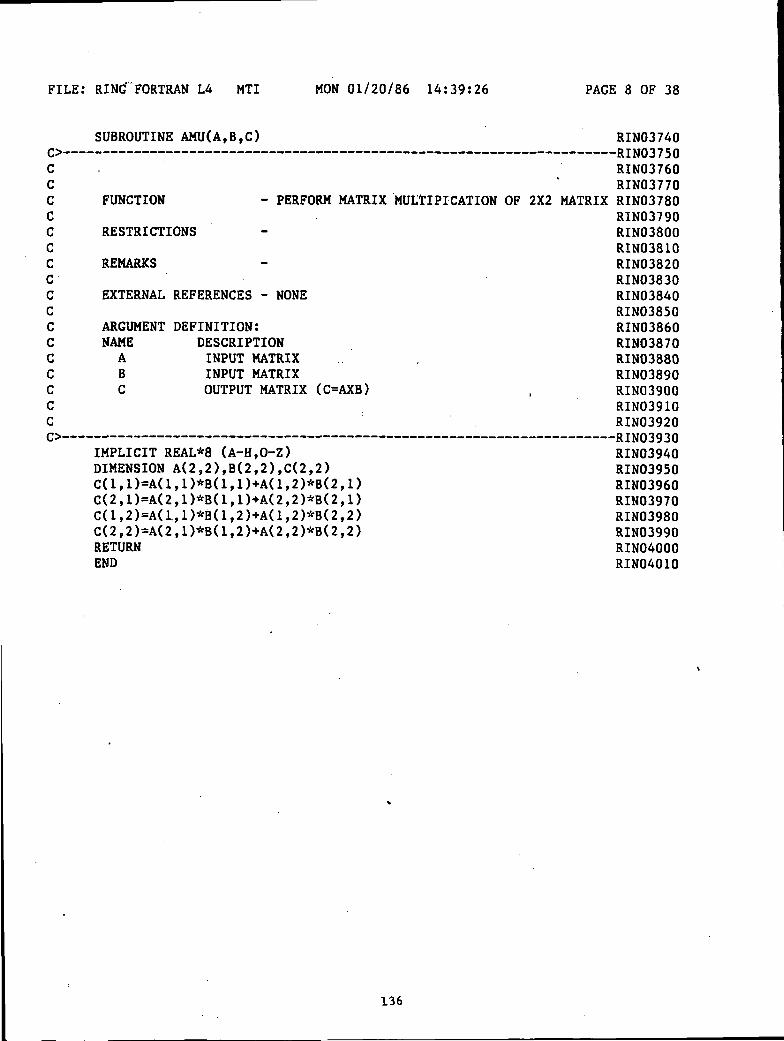
FILE: RING"FORTRAN LA MTI MON 01/20/86 14:39:26 PAGE 8 OF 38
ccccccccccccccccc
SUBROUTINE AMU(A,B,C)
FUNCTION - PERFORM MATRIX
RESTRICTIONS
REMARKS
EXTERNAL REFERENCES - NONE
ARGUMENT DEFINITION:NAME DESCRIPTIONA INPUT MATRIXB INPUT MATRIXC OUTPUT MATRIX (C=AXB)
IMPLICIT REAL*8 (A-H,0-Z)DIMENSION A(2,2),B(2,2),C(2,2)C(1,1)-A(1,1)*B(1,1)+A(1,2)*B(2,1)C(2,1)=A(2,1)*B(1,1)+A(2,2)*B(2,1)C(1,2)=A(1.,1)*B(1,2)+A(1,2)*B(2,2)C(2,2)=A(2,1)*B(1,2)+A(2,2)*B(2,2)RETURNEND
RIN03740
RIN03760RIN03770
MULTIPICATION OF 2X2 MATRIX RIN03780RIN03790RIN03800RIN03810RIN03820RIN03830RIN03840RIN03850RIN03860RIN03870RIN03880RIN03890RIN03900RIN03910RIN03920
RIN03940RIN03950RIN03960RIN03970RIN03980RIN03990RIN04000RIN04010
136
FILE: RING FORTRAN L4 MTI MON 01/20/86 14:39:26 PAGE 9 OF 38
cccccccccccccc
c
'
100
SUBROUTINE CALCD
FUNCTION - CALCULATE INFLUENCE COEFFICIENTS C,DFOR H AND H' AT PSI=1
RESTRICTIONS - FOR MULTIPLE RUNS, ONLY COMPUTED WHENCERTAIN PARAMETERS CHANGE. ALWAYSCOMPUTED AT LEAST ONCE.
REMARKS - NOTE VARIABLES PASSED IN COMMON
EXTERNAL REFERENCES - AIN,AMU,RUK
IMPLICIT REAL*8 (A-H,0-Z)COMMON/BCD /XLOC(IOO) ,C(100) ,D(100) ,NDX(3) ,NDP(3) ,DX(3) ,DP(3)COMMON/BELAS /FORCE, HELAS, H1ELAS, H2ELAS, H3ELAS, Wl(4) ,W2(4)COMMON/BPAR /AL, BET,PO,EPS,PF,S,U,DTCOMMON/BFLAG /IFLAG,IPLOADDIMENSION YO(4),YT(4),DJ(4),CKJ(4,4)DIMENSION XLEN(3)DIMENSION Al( 2, 2,100 ),A2( 2, 2, 100)DIMENSION 81(2,2,100), 82(2,2,100)DIMENSION A1I(2,2),AT(2,2)EXTERNAL DFN1
XLEN(1)=DX(1)*NDX(1)XLEN(2)=DX(2)*NDX(2)XLEN(3)=DX(3)*NDX(3)EL1=XLEN(1)Y0(l)=0.Y0(2)=0.Y0(3)=l.Y0(4)=0.CALL RUK(DX(1),XLEN(1),-EL1,XNN,YO,YO,4,DFN1,YT,DJ,CKJ,4)CALL RUK(DX(2)/2.,DP(2)/2.,XNN,XNN,YO,YO,4,DFN1,YT,DJ,CKJ,4)XLOC(1)=XNNA1(1,1,1)=YO(1)A1(2,1,1)=YO(2)A2(1,1,1)=YO(3)A2(2,1,1)=YO(4)DO 100 I=2,NDP(2)CALL RUK(DX(2),DP(2),XNN,XNN,YO,YO,4,DFN1,YT,DJ,CKJ,4)XLOC(I)=XNNA1(1,1,I)=YO(1)A1(2,1,I)=YO(2)A2(1,1,I)=YO(3)A2(2,1,I)=YO(4)CALL RUK(DX(2)/2.,DP(2)/2.,XNN,XNN,YO,YO,4,DFN1,YT,DJ,CKJ,4)IF(IFLAG.EQ.2)GOTO 111CALL RUK(DX(3)/2.,DP(3)/2.,XNN,XNN,YO,YO,4,DFN1,YT,DJ,CKJ,4)XLOC(NDP(2)-»-l)=XNN
137
RIN04020
RIN04040RIN040SORIN04060RIN04070RIN04080RIN04090RIN04100RIN04110RIN04120RIN04130RIN04140RIN04150RIN04160RIN04170
RIN04190RIN04200RIN04210RIN04220RIN04230RIN04240RIN04250RIN04260RIN04270RIN04280RIN04290RIN04300RIN04310RIN04320RIN04330RIN04340RIN04350RIN04360RIN04370RIN04380RIN04390RIN04400RIN04410RIN04420RIN04430RIN04440RIN04450RIN04460RIN04470RIN04480RIN04490RIN04500RIN04510RIN04520RIN04530RIN04540RIN04550RIN04560
FILE: RING FORTRAN LA MTI MON 01/20/86 14:39:26 PAGE 10 OF 38
101
111
200
201
112
A1(1,1,NDP(2)+1)=YO(1)A1(2,1,NDP(2)+1)=YO(2)A2(1,1,NDP(2)+1)=YO(3)A2(2,1,NDP(2)-H)=YO(4)DO 101 I=2,NDP(3)CALL RUK(DX(3),DP(3),XNN,XNN,YO,YO,4,DFN1,YT,DJ,CKJ,4) .XLOC(NDP(2)+I)=XNNA1(1,1,NDP(2)+I)=YO(1)A1(2,1,NDP(2)+I)=YO(2)A2(1,1,NDP(2)+I)=YO<3)A2(2,1,NDP(2)+I)=YO(4)CALL RUK(DX(3)/2.,DP(3)/2.,XNN,XNN,YO,YO,4,DFN1,YT,DJ,CKJ,4)W1(1)=YO(1)W1(2)=YO(2)W1(3)=YO(3)W1(4)=YO(4) ,
Y0(l)=0.Y0(2)=0.Y0(3)=0.Y0(4)=l.CALL RUK(DX(1),XLEN(1),-EL1,XNN,YO,YO,4,DFN1,YT,DJ,CKJ,4)CALL RUK(DX(2)/2.,DP(2)/2.,XNN,XNN,YO,YO,4,DFN1,YT,DJ,CKJ,4)
A1(2,2,,1)»YO(2)A2(1,2,1)=YO(3)A2(2,2,1)=YO(4)DO 200 I=2,NDP(2)CALL RUK(DX(2),DP(2),XNN,XNN,YO,YO,4,DFN1,YT,DJ,CKJ,4)
A1(2,2,I)=YO(2)A2(1,2,I)=YO(3)A2(2,2,I)=YO(4)CALL RUK(DX(2)/2.,DP(2)/2.,XNN,XNN,YO,YO,4,DFN1,YT,DJ,CKJ,4)IF(IFLAG.E.Q.2)GOTO 112CALL RUK(DX(3)/2.,DP(3)/2.,XNN,XNN,YO,YO,4,DFN1,YT,DJ,CKJ,4)A1(1,2,NDP(2)+1)=YO(1)A1(2,2,NDP(2)+1)=YO(2)A2(1,2,NDP(2)+1)=YO(3) . -A2(2,2,NDP(2)+1)=YO(4)DO 201 I=2,NDP(3)CALL RUK(DX(3),DP(3),XNN,XNN,YO,YO,4,DFN1,YT,DJ,CKJ,4)A1(1,2,NDP(2)-H)=YO(1)A1(2,2,NDP(2)+I)=YO(2)A2(1,2,NDP(2)-H)=YO(3)A2(2,2,NDP(2)-H)=YO(4)CALL RUK(DX(3)/2.,DP(3)/2.,XNN,XNN,YO,YO,4,DFN1,YT,DJ,CKJ,4)W2(1)=YO(1)W2(2)=YO(2)W2(3)=YO(3)W2(4)=YO(4) i
Y0(l)=l.Y0(2)=0.Y0(3)=0.
RIN04570RIN04580RIN04590RIN04600RIN04610RIN04620RIN04630RIN04640RIN04650RIN04660;RIN04670RIN04680RIN04690RIN04700RIN04710RIN04720RIN04730RIN04740RIN04750RIN04760RIN04770RIN04780RIN04790RIN04800RIN04810RIN04820RIN04830RIN04840RIN04850RIN04860RIN04870RIN04880RIN04890RIN04900RIN04910RIN04920RIN04930RIN04940RIN04950RIN04960RIN04970RIN04980RIN04990RIN05000RIN05010RIN05020RIN05030RIN05040RIN05050RINOS060RIN05070RIN05080RIN05090RIN05100RIN05110
138
FILE: RING FORTRAN L4 MTI MON 01/20/86 14:39:26 PAGE 11 OF 38
Y0(4)=0. RIN05120XNN=1. RIN05130IF(IFLAG.EQ.2)GOTO 113 RIN05140CALL RUK(-DX(3)/2.,-DP(3)/2.,XNN,XNN,YO,YO,4,DF'Nl,YT,DJ,CKJ,4) RIN05150B1(1,1,NDP(2)+NDP(3))=YO(1) RIN05160B1(2,1,NDP(2)+NDP(3))=YO(2) RIN05170B2(1,1,NDP(2)+NDP(3))=YO(3) RIN05180B2(2,1,NDP(2)+NDP(3»=YO(4) RIN05190DO 300 II=2,NDP(3) RIN05200I=NDP(2)+NDP(3)-II+1 RIN05210CALL RUK(-DX(3),-DP(3),XNN,XNN,YO,YO,4,DFN1,YT,DJ,CKJ,4) RIN05220B1(1,1,I)=YO(1) RIN05230B1(2,1,I)=YO(2) RIN05240B2(1,1,I)=YO(3) RIN05250
300 B2(2,1,I)=YO(4) RIN05260CALL RUK(-DX(3)/2.,-DP(3)/2.,XNN,XNN,YO,YO,4,DFNl,YT,DJ,CKJ,4) RIN05270
113 CALL RUK(-DX(2)/2.,-DP(2)/2.,XNN,XNN,YO,YO,4,DFNl,YT,DJ,CKJ,4) RIN05280B1(1,1,NDP(2))=YO(1) RIN05290B1(2,1,NDP(2))=YO(2) RIN05300B2(1,1,NDP(2))=YO(3) RIN05310B2(2,1,NDP(2))=YO<4) RIN05320DO 301 II=2,NDP(2) RIN05330I=NDP(2)-II+1 RIN05340CALL RUK(-DX(2),-DP(2),XNN,XNN,YO,YO,4,DFN1,YT,DJ,CKJ,4) RIN05350Bl(i,l,I)=YO(l) RIN05360B1(2,1,I)=YO(2) RIN05370B2(1,1,I)=YO(3) RIN05380.
301 B2(2,1,I)=YO(4) RIN05390C - RIN05400
Y0(l)=0. RIN05410Y0(2)=l. RIN05420
• Y0(3)=0. RIN05430Y0(4)=0. RIN05440XNN*1. RIN05450IF(IFLAG.EQ.2)GOTO 114 RIN05460CALL RUK(-DX(3)/2.,-DP(3)/2.,XNN,XNN,YO,YO,4,DFNl,YT,DJ,CKJ,^) RIN05470B1(1,2,NDP(2)+NDP(3))=YO(1) RIN05480B1(2,2,NDP(2)+NDP(3))=YO(2) RIN05490B2(1,2,NDP(2)+NDP(3))=YO(3) RIN05500B2(2,2,NDP(2)+NDP(3))=YO(4) RIN05510DO 400 II=2,NDP(3) RIN05520I=NDP(2)+NDP(3)-II+1 RIN05530CALL RUK(-DX(3),-DP(3),XNN,XNN,YO,YO,4,DFN1,YT,DJ,CKJ,4) RIN05540B1(1,2,I)=YO(1) ' RIN05550B1(2,2,I)=YO(2) . . ' RIN05560B2(1,2,I)=YO(3) RIN05570
400 B2(2,2,I)=YO(4) RIN05580CALL RUK(-DX(3)/2.,-DP(3)/2.,XNN,XNN,YO,YO,4,DFNl,YT,DJ,CKJ,4) RIN05590
114 CALL RUK(-DX(2)/2.,-DP(2)/2.,XNN,XNN,YO,YO,4,DFNl,YT,DJ,CKJ,4) RIN05600B1(1,2,NDP(2))=YO(1) ' RIN0561081(2,2,NDP(2))=YO(2) RIN05620B2(1,2,NDP(2))=YO(3) RIN05630B2(2,2,NDP(2))=YO(4) RIN05640DO 401 II=2,NDP(2) RIN05650I=NDP(2)-II+1 RIN05660
139

FILE: RING FORTRAN L4 MTI MON 01/20/86 14:39:26 PAGE 12 OF 38
CALL RUK(-DX(2),-DP(2),XNN,XNN,YO,YO,4,DFN1,YT,DJ,CKJ,4)
401C
21
500
22
501C
B1(2,2,I)=YO(2)B2(1,2,I)=YO(3)B2(2,2,I)=YO(4)
DO 500 I=1,NDP(2)CALL AIN(A1(1,1,I),A1I)CALL AMU(A2(1,1,I),A1I,AT)'CALL AMU(AT,B1(1,1,I),A1(1,1,I))DO 21 11=1,2DO 21 JJ=1,2AT(II,JJ)=B2(II,JJ,I)-A1(II,JJ,I)CALL AIN(AT,B2( 1,1,1))C(I)=B2(1,2,I)/AL*DP(2)D(I)=B2(2,2,I)/AL*DP(2)CONTINUEIF(IFLAG.EQ.2)RETURNINDEX1=NDP(2)+1INDEX2=NDP( 2 )+NDP( 3 )DO 501 I=INDEX1,INDEX2CALL AIN(A1(1,1,I),A1I)CALL AMU(A2(1,1,I),A1I,AT)CALL AMU(AT,B1(1,1,I),A1(1,1,I))DO 22 11=1,2DO 22 JJ=1,2AT(II,JJ)=B2(II,JJ,I)-A1(II,JJ,I)CALL AIN(AT,B2( 1,1,1))C(I)=B2(1,2,I)/AL*DP(3)D(I)=B2(2,2,I)/AL*DP(3)CONTINUE
RETURNEND
RIN05670RIN05680RIN05690RIN05700RIN05710RIN05720RIN05730RIN05740RIN05750RIN05760RIN05770RIN05780RIN05790RIN05800RIN05810RIN05820RIN05830RIN05840RIN05850RIN05860RIN05870RIN05880RIN05890RIN05900RIN05910RIN05920RIN05930RIN05940RIN05950RIN05960RIN05970RIN05980RIN05990RIN06000
140

FILE: RING FORTRAN L4 MTI MON 01/20/86 14:39:26 PAGE 1-3 OF 38
cccccccccccccc
c
100
SUBROUTINE CALCD3
FUNCTION - CALCULATE INFLUENCE COEFFICIENTS C,DFOR H AND H1 AT PSI=1
RESTRICTIONS - FOR MULTIPLE RUNS, ONLY COMPUTED WHENCERTAIN PARAMETERS CHANGE. ALWAYSCOMPUTED AT LEAST ONCE.
REMARKS - NOTE VARIABLES PASSED IN COMMON
EXTERNAL REFERENCES - AIN,AMU,RUK
IMPLICIT REAL*8 (A-H,0-Z)COMMON/BCD /XLOC(IOO) ,C(100) ,D(100) ,NDX(3) ,NDP(3) ,DX(3) ,DP(3)COMMON/BELAS /FORCE, HELAS, H1ELAS, H2ELAS, H3ELAS, Wl(4) ,W2(4)COMMON/ BPAR / AL , BET , PO , EPS , PF , S , U , DTCOMMON/BFLAG /IFLAG,IPLOADDIMENSION YO(4),YT(4),DJ(4),CKJ(4,4)DIMENSION XLEN(3)DIMENSION A1(2,2,100),A2(2,2,100)DIMENSION 81(2, 2, 100), 82(2, 2, 100)DIMENSION A1I(2,2),AT(2,2)EXTERNAL DFN1
XLEN(1)=DX(1)*NDX(1)XLEN(2)=DX(2)*NDX(2)XLEN(3)=DX(3)*NDX(3)EL1=XLEN(1)+XLEN(2)Y0(l)=0.Y0(2)=0.Y0(3)=l.Y0(4)=0.CALL RUK(DX(1),XLEN(1),-EL1,XNN,YO,YO,4,DFN1,YT,DJ,CKJ,4)CALL RUK(DX(2)/2.,DP(2)/2.,XNN,XNN,YO,YO,4,DFN1,YT,DJ,CKJ,4)XLOC(1)=XNNA1(1,1,1)=YO(1)A1(2,1,1)=YO(2)A2(1,1,1)=YO(3)A2(2,1,1)=YO(4)DO 100 I=2,NDP(2)CALL RUK(DX(2),DP(2),XNN,XNN,YO,YO,4,DFN1,YT,DJ,CKJ,4)XLOC(I)=XNNA1(1,1,T)=YO(1)A1(2,1,I)=YO(2)A2(1,1,I)=YO(3)A2(2,1,I)=YO(4)CALL RUK(DX(2)/2.,DP(2)/2.,XNN,XNN,YO,YO,4,DFN1,YT,DJ,CKJ,4)CALL RUK(DX(3)/2.,DP(3)/2.,XNN,XNN,YO,YO,4,DFN1,YT,DJ,CKJ,4)XLOC(NDP(2)+1)=XNNA1(1,1,NDP(2)+1)=YO(1)
141
RIN06010
RIN06030RIN06040RIN06050RIN06060RIN06070RIN06080RIN06090RIN06100RIN06110RIN06120RIN06130RIN06140RIN06150RIN06160
RIN06180RIN06190RIN06200RIN06210RIN06220RIN06230RIN06240RIN06250RIN06260RIN06270RIN06280RIN06290RIN06300RIN06310RIN06320RIN06330RIN06340RIN06350RIN06360RIN06370RIN06380RIN06390RIN06400RIN06410RIN06420RIN06430RIN06440RIN06450RIN06460RIN06470RIN06480RIN06490RIN06500RIN06510RIN06520RIN06530RIN06540RIN06550
FILE: RING .FORTRAN L4 MTI MON 01/20/86 14:39:26 PAGE 14 OF 38
101
200
201
A1(2,1,NDP(2)+1)=YO(2)A2(1,1,NDP(2)+1)=YO(3)A2(2,1,NDP(2)+1)=YO(4) ,D O 1 0 1 I=2,NDP(3) ; . . . . . 'CALL RUK(DX(3),DP(3),XNN,XNN,YO,YO,4,DFN1,YT,DJ,CKJ,4)XLOC(NDP(2)+I)=XNNA1(1,1,NDP(2)+I)=YO(1)A1(2,1,NDP(2)+I)=YO(2) , lt .A2(1,1,NDP(2)+I)=YO(3) 'A2(2,1,NDP(2)-H)=YO(4)CALL RUK(DX(3)/2.,DP(3)/2.,XNN,XNN,YO,YO,4,DFN1,YT,DJ,CKJ,4)W1(1)=YO(1)W1(2)=YO(2) . . . . .W1(3)=YO(3)W1(4)=YO(4)
Y0(l)=0.Y0(2)=0.Y0(3)=0.Y0(4)=l.CALL RUK(DX(1),XLEN(1),-EL1,XNN,YO,YO,4,DFN1,YT,DJ,CKJ,4)CALL RUK(DX(2)/2.,DP(2)/2.,XNN,XNN,YO,YO,4,DFNl,YTfDJ,CKJ,4)
A1(2,2,1)=YO(2)A2(1,2,1)=YO(3)A2(2,2,1)=YO(4)DO 200 I=2,NDP(2)CALL RUK(DX(2),DP(2),XNN,XNN,YO,YO,4,DFN1,YT,DJ,CKJ,4)
A1(2,2,I)=YO(2)A2(1,2,I)=YO(3)A2(2,2,I)=YO(4) . .. .CALL RUK(DX(2)/2.,DP(2)/2.,XNN,XNN,Yb,Y6,4,DFNl,YT,DJ,CKJ,4)CALL RUK(DX(3)/2.,DP(3)/2.,XNN,XNN,YO,YO,4,DFN1,YT,DJ,CKJ,4)A1(1,2,NDP(2)+1)=YO(1)A1(2,2,NDP(2)+1)=YO(2)A2(1,2,NDP(2)+1)=YO(3)A2(2,2,NDP(2)+1)=YO(4)DO 201 I=2,NDP(3)CALL RUK(DX(3),DP(3),XNN,XNN,YO,YO,4,DFN1,YT,DJ,CKJ,4)A1(1,2,NDP(2)+I)=YO(1)A1(2,2,NDP(2)-H)=YO(2)A2(1,2,NDP(2)+I)=YO(3)A2(2,2,NDP(2)+I)=YO(4) .CALL RUK(DX(3)/2.,DP(3)/2.,XNN,XNN,YO,YO,4,DFN1,YT,DJ,CKJ,4)W2(1)=YO(1)W2(2)=YO(2)W2(3)=YO(3)W2(4)=YO(4)
Y0(l)=l.Y0(2)=0. • : .Y0(3)=0.Y0(4)=0.XNN=1.
RIN06560RIN06570RIN06580RIN06590RIN06600RIN06610RIN06620RIN06630RIN06640RIN06650RIN06660RIN06670RIN06680RIN06690RIN06700RIN06710RIN06720RIN06730RIN06740RIN06750RIN06760RIN06770RIN06780RIN06790RIN06800RIN06810RIN06820RIN06830RIN06840RIN06850RIN06860RIN06870RIN06880RIN06890RIN06900RINO6910RIN06920RIN06930RIN06940RIN06950RIN06960RIN06970RIN06980RIN06990RIN07000RIN07010RIN07020RIN07030RIN07040RIN07050RIN07060RIN07070RIN07080RIN07090RIN07100
. 142

FILE: RING FORTRAN L4 MTI MON 01/20/86 14:39:26 PAGE 15 OF 38
300
301C
400
114
CALL RUK(-DX(3)/2.,-DP(3)/2.,XNN,XNN,YO,YO,4,DFNl,YT,DJ,CKJ,4)B1(1,1,NDP(2)+NDP(3))=YO(1)B1(2,1,NDP(2)+NDP(3))=YO(2)B2(1,1,NDP(2)+NDP(3))=YO(3)B2(2,1,NDP(2)+NDP(3))=YO(4)DO 300 II=2,NDP(3)I=NDP(2)+NDP(3)-II+1CALL RUK(-DX(3),-DP(3),XNN,XNN,YO,YO,4,DFN1,YT,DJ,CKJ,4)
B1(2,1,I)=YO(2)B2(1,1,I)=YO(3)82(2,1,I)=YO(4)CALL RUK(-DX(3)/2.,-DP(3)/2.,XNN,XNN,YO,YO,4,DFNl,YT,DJ,CKJ,4)CALL RUK(-DX(2)/2,,-DP(2)/2.,XNN,XNN,YO,YO,4,DFNl,YT,DJ,CKJ,4)B1(1,1,NDP(2))=YO(1)B1(2,1,NDP(2))=YO(2)B2(1,1,NDP(2))=YO(3)B2(2,1,NDP(2))=YO(4)DO 301 II=2,NDP(2)I=NDP(2)-II+1CALL RUK(-DX(2),-DP(2),XNN,XNN,YO,YO,4,DFN1,YT,DJ,CKJ,4)
B1(2,1,I)=YO(2)B2(1,1,I)=YO(3)B2(2,1,I)=YO(4)
Y0(l)=0.Y0(2)=l.Y0(3)=0.Y0(4)=0.XNN=1.CALL RUK(-DX(3)/2.,-DP(3)/2.,XNN,XNN,YO,YO,4,DFNl,YT,DJ,CKJ,4)B1(1,2,NDP(2)+NDP(3))=YO(1)B1(2,2,NDP(2)+NDP(3))=YO(2)B2(1,2,MDP(2)+NDP(3))=YO(3)B2(2,2,MDP(2)+NDP(3))=YO(4)DO 400 II=2,NDP(3)I=NDP(2)+NDP(3)-II-HCALL RUK(-DX(3),-DP(3),XNN,XNN,YO,YO,4,DFN1,YT,DJ,CKJ,4)
B1(2,2,I)=YO(2) ' v
B2(1,2,I)=YO(3) :' -B2(2,2,I)=YO(4) =;
CALL RUK(-DX(3)/2.,-DP(3)/2.,XNN,XNN,YO,YO,4,DFNl,YT,DJ,CKJ,4)CALL RUK(-DX(2)/2.,-DP(2)/2.,XNN,XNN,YO,YO,4,DFNl,YT,DJ,CKJ,4)B1(1,2,NDP(2))=YO(1)B1(2,2,NDP(2))=YO(2)B2(1,2,NDP(2))=YO(3)B2(2,2,NDP(2))=YO(4)DO 401 II=2,NDP(2)I=NDP(2)-II+1CALL RUK(-DX(2),-DP(2),XNN,XNN,YO,YO,4,DFN1,YT,DJ,CKJ,4)
143
B1(2,2,I)=YO(2)B2(1,2,I)=YO(3)
RIN07110RIN07120RIN07130RIN07140RIN07150RIN07160RIN07170RIN07180RIN07190RIN07200RIN07210RIN07220RIN07230RIN07240RIN07250RIN07260RIN07270RIN07280RIN07290RIN07300RIN07310RIN07320RIN07330RIN07340RIN07350RIN07360RIN07370RIN07380RIN07390RIN07400RIN07410RIN07420RIN07430RIN07440RIN07450RIN07460RIN07470RIN07480RIN07490RIN07500RIN07510RIN07520RIN07530RIN07540RIN07550RIN07560RIN07570RIN07580RIN07590RIN07600RIN07610RIN07620RIN07630RIN07640RIN07650
FILE: RING FORTRAN L4 MTI MON 01/20/86 14:39:26 PAGE 16 OF 38
401C
21
500
22
501C
B2(2,2,I)=YO(4)
DO 500 I=1,NDP(2)CALL AIN(A1(1,1,I),A1I)CALL AMU(A2(1,1,I),A1I,AT)CALL AMU(AT,B1(1,1,I),A1(1,1,I))DO 21 11=1,2DO 21 JJ=1,2AT(II,JJ)=B2(II,JJ,I)-A1(II,JJ,I)CALL AIN(AT,B2(1,1,I))C(I)=B2(1,2,I)/AL*DP(2)D(I)=B2(2,2,I)/AL*DP(2)CONTINUEINDEX1=NDP(2)+1INDEX2=NDP(2)+NDP(3)DO 501 I=INDEX1,INDEX2CALL AIN(A1(1,1,I),A1I)CALL AMU(A2(1,1,I),A1I,AT)CALL AMU(AT,B1(1,1,I),A1(1,1,D)DO 22 11=1,2DO 22 JJ=1,2AT(II,JJ)=B2(II,JJ,I)-A1(II,JJ,I)CALL AIN(AT,B2(1,1,I))C(I)=B2(1,2,I)/AL*DP(3)D(I)=B2(2,2,I)/AL*DP(3)CONTINUE
RETURNEND
RIN07660RIN07670RIN07680RIN07690RIN07700RIN07710RIN07720RIN07730RIN07740RIN07750RIN07760RIN07770RIN07780RIN07790RIN07800RIN07810RIN07820RIN07830RIN07840RIN07850RIN07860RIN07870RIN07880RIN07890RIN07900RIN07910RIN07920RIN07930RIN07940
144

FILE: RING FORTRAN L4 MTI MON 01/20/86 14:39:26 PAGE 17 OF 38
cccccccccccccc
c
100
SUBROUTINE CALCD4
FUNCTION - CALCULATE INFLUENCE COEFFICIENTS C,DFOR H AND H' AT PSI=1
RESTRICTIONS - FOR MULTIPLE RUNS, ONLY COMPUTED WHENCERTAIN PARAMETERS CHANGE. ALWAYSCOMPUTED AT LEAST ONCE.
REMARKS - NOTE VARIABLES PASSED IN COMMON
EXTERNAL REFERENCES - AIN,AMU,RUK
IMPLICIT REAL*8 (A-H,0-Z)COMMON/BCD /XLOC( 100),C( 100) ,D( 100) ,NDX(3) ,NDP(3) ,DX(3) ,DP(3)COMMON/BELAS /FORCE, HELAS, H1ELAS, H2ELAS, H3ELAS, Wl(4) ,W2(4)COMMON/BPAR /AL,BET,PO,EPS,PF,S,U,DTCOMMON /BFLAG /IFLAG.IPLOADDIMENSION Y0(4) ,YT(4) ,DJ(4) ,CKJ(4,4)DIMENSION XLEN(3)DIMENSION A1(2,2,100),A2(2,2,100)DIMENSION 81(2,2,100), 82(2,2,100)DIMENSION A1I(2,2),AT(2,2)EXTERNAL DFN1
XLEN(1)=DX(1)*NDX(1)XLEN(2)=DX(2)*NDX(2)XLEN(3)=DX(3)*NDX(3)EL1=XLEN( 1 )Y0(l)=0.Y0(2)=0.Y0(3)=l.Y0(4)=0.CALL RUK(DX(l)/2.,DP(l)/2.,-ELl,XNN,YO,YO,4,DFNl,YT,DJ,CKJ,4)XLOC(1)=XNNA1(1,1,1)=YO(1)A1(2,1,1)=YO(2)A2(1,1,1)=YO(3)A2(2,1,1)=YO(4)DO 100 I=2,NDP(1)CALL RUK(DX(1),DP(1),XNN,XNN,YO,YO,4,DFN1,YT,DJ,CKJ,4)XLOC(I)=XNNA1(1,1,I)=YO(1)A1(2,1,I)=YO(2)A2(1,1,I)=YO(3)A2(2,1,I)=YO(4)CALL RUK(DX(1)/2.,DP(1)/2.,XNN,XNN,YO,YO,4,DFN1,YT,DJ,CKJ,4)CALL RUK(DX(2)/2.,DP(2)/2.,XNN,XNN,YO,YO,4,DFN1,YT,DJ,CKJ,4)XLOC(NDP(1)+1)=XNNA1(1,1,NDP(1)-H)=YO(1)A1(2,1,NDP(1)+1)=YO(2)
RIN07950
RIN07970RIN07980RIN07990RIN08000RIN08010RIN08020RIN08030RIN08040RIN08050RIN08060RIN08070RIN08080RIN08090RIN08100
RIN08120RIN08130RIN08140RIN08150RIN08160RIN08170RIN08180RIN08190RIN08200RIN08210RIN08220RIN08230RIN08240RIN08250RIN08260RIN08270RIN08280RIN08290RIN08300RIN08310RIN08320RIN08330RIN08340RIN08350RIN08360RIN08370RIN08380RIN08390RIN08400RIN08410RIN08420RIN08430RIN08440RIN08450RIN08460RIN08470RIN08480RIN08490
145
FILE: RING FORTRAN L4 MTI MON 01/20/86 14:39:26 PAGE 18 OF 38
A2(1,1,NDP(1)+1)=YO(3) RIN08500A2(2,i,NDP(D + l)=YO(4) RIN08510
' DO 101 I=2,NDP(2) RIN08520CALL RUK(DX(2).,DP(2),XNN,XNN,YO,YO,4,DFN1,YT,DJ,CKJ,4) • RIN08530XLOC(NDP(1)+I)=XNN RIN08540A1(1,1,NDP(1)+I)=YO(1) RIN08550A1(2,1,NDP(1)+I)=YO(2) RIN08560A2(1,1,NDP(D-H)=YO(3) RIN08570
101 A2(2,1,NDP(D+I)=YO(4) RIN08580CALL RUK(DX(2)/2.,DP(2)/2.,XNN,XNN,YO,YO,4,DFN1,YT,DJ,CKJ,4) RIN08590W1(1)=YO(1) RIN08600W1(2)=YO(2) J RIN08610W1(3)=YO(3) RIN08620W1(4)=YO(4) RIN08630
C RIN08640Y0(l)=0. RIN08650Y0(2)=0. . RIN08660Y0(3)=0. . RIN08670Y0(4)=l. RIN08680CALL RUK(DX(l)/2.,DP(l)/2.,-ELl,XNN,YO,YO,4,DFNl,YT,DJ,CKJ,4) RIN08690A1(1,2,1)=YO(1) RIN08700A1(2,2,1)=YO(2) RIN08710A2(1,2,1)=YO(3) RIN08720A2(2,2,1)=YO(4) RIN08730DO 200 I=2,NDP(1) . RIN08740CALL RUK(DX(1),DP(1),XNN,XNN,YO,YO,4,DFN1,YT,DJ,CKJ,4) RIN08750A1(1,2,I)=YO(1) RIN08760A1(2,2,I)=YO(2) RIN08770A2(1,2,I)=YO(3) RIN08780
200 A2(2,2,I)-YO(4) . RIN08790CALL RUK(DX(1)/2.,DP(1)/2.,XNN,XNN,YO,YO,4,DFN1,YT,DJ,CKJ,4) RIN08800CALL RUK(DX(2)/2.,DP(2)/2.,XNN,XNN,YO,YO,4,DFN1,YT,DJ,CKJ,4) RIN08810A1(1,2,NDP(1)-H)=YO(1) RIN08820A1(2,2,NDP(1)*1)=YO(2) RIN08830A2(1,2,NDP(1)+1)=YO(3) RIN08840A2(2,2,NDP(1)+1)=YO(4) RIN08850DO 201 I=2,NDP(2) RIN08860CALL RUK(DX(2),DP(2),XNN,XNN,YO,YO,4,DFN1,YT,DJ,CKJ,4) RIN08870A1(1,2,NDP(1)+I)=YO(1) RIN08880A1(2,2,NDP(1)+I)=YO(2) RIN08890A2(1,2,NDP(1)+I)=YO(3) RIN08900
201 A2(2,2,NDP(1)+I)=YO(4) RIN08910CALL RUK(DX(2)/2.,DP(2)/2.,XNN,XNN,YO,YO,4,DFN1,YT,DJ,CKJ,4) RIN08920W2(1)=YO(1) RIN08930W2(2)=YO(2) . RIN08940W2(3)=YO(3) RIN08950W2(4)=YO(4). RIN08960
C RIN08970Y0(l)=l. RIN08980Y0(2)=0. RIN08990Y0(3)=0. ' RIN09000Y0(4)=0. RIN09010XNN=1. RIN09020CALL RUK(-DX(2)/2.,-DP(2)/2.,XNN,XNN,YO,YO,4,DFNl,YT,DJ,CKJ,4) ' RIN09030B1(1,1,NDP(1)+NDP(2))=YO(1) RIN09040
146

FILE: RING FORTRAN L4 MTI MON 01/20/86 14:39:26 PAGE 19 OF 38
B1(2,1,NDP(1)+NDP(2))=YO(2) RIN09050B2(1,1,NDP(1)+NDP(2))=YO(3) RIN09060B2(2,1,NDP(1)+NDP(2))=YO(4) . RIN09070DO 300 II=2,NDP(2) RIN09080I=NDP(1)+NDP(2)-II+1 RIN09090CALL RUK(-DX(2),-DP(2),XNN,XNN,YO,YO,4,DFN1,YT,DJ,CKJ,4) RIN09100B1(1,1,I)=YO(1) . RIN09110B1(2,1,I)=YO(2) RIN09120B2(1,1,I)=YO(3) , RIN09130
300 B2(2,1,I)=YO(4) RIN09140CALL RUK(-DX(2)/2.,-DP(2)/2.,XNN,XNN,YO,YO,4,DFNl,YT,DJ,CKJ,4) RIN09150CALL RUK(-DX(l)/2.,-DP(l)/2.,XNN,XNN,YO,YO,4,DFNl,YT,DJ,CKJ,4) RIN09160B1(1,1,NDP(1))=YO(1) RIN09170B1(2,1,NDP(1))=YO(2) RIN0918082(1,1,NDP(1))=YO(3) RIN09190B2(2,1,NDP(1))=YO(4) RIN09200DO 301 II=2,NDP(1) RIN09210I=NDP(1)-II+1 RIN09220CALL RUK(-DX(1),-DP(1),XNN,XNN,YO,YO,4,DFN1,YT,DJ,CKJ,4) RIN09230B1(1,1,I)=YO(1) RIN09240B1(2,1,I)=YO(2) . • - RIN09250B2(1,1,I)=YO(3) RIN09260
301 B2(2,1,I)=YO(4) RIN09270C RIN09280
Y0(l)=0. • - . - . - . RIN09290Y0(2)=l. RIN09300Y0(3)=0. RIN09310Y0(4)=0. RIN09320XNN=1. RIN09330CALL RUK(-DX(2)/2.,-DP(2)/2.,XNN,XNNfYO,YO,4,DFNl,YT,DJ,CKJ,4) RIN09340B1(1,2,NDP(1)+NDP(2))=YO(1) . RIN09350B1(2,2,NDP(1)+NDP(2))=YO(2) RIN09360B2(1,2,NDP(1)+NDP(2))=YO(3) RIN09370B2(2,2,NDP(1)+NDP(2))=YO(4) RIN09380DO 400 II=2,NDP(2) RIN09390I=NDP(1)+NDP(2)-II-H RIN09400CALL RUK(-DX(2),-DP(2),XNN,XNN,YO,YO,4,DFN1,YT,DJ,CKJ,4) RIN09410B1(1,2,I)=YO(1) RIN09420B1(2,2,I)=YO(2) RIN09430B2(1,2,I)=YO(3) RIN09440
400 B2(2,2,I)=YO(4) RIN09450CALL RUK(-DX(2)/2.,-DP(2)/2.,XNN,XNN,YO,YO,4,DFNl,YT,DJ,CKJ,4). .RIN09460CALL RUK(-DX(l)/2.,-DP(l)/2.,XNN,XNN,YO,YO,4,DFNl,YT,DJ,CKJ,4) RIN09470B1(1,2,NDP(1))=YO(1) RIN09480B1(2,2,NDP(1))=YO(2) RIN09490B2(1,2,NDP(1))=YO(3) RIN09500B2(2,2,NDP(1))=YO(4) RIN09510DO 401 II=2,NDP(1) RIN09520I=NDP(1)-II+1 RIN09530CALL RUK(-DX(1),-DP(1),XNN,XNN,YO,YO,4,DFN1,YT,DJ,CKJ,4) RIN09540B1(1,2,I)=YO(1) RIN09550B1(2,2,I)=YO(2) RIN09560B2(1,2,I)=YO(3) RIN09570
401 B2(2,2,I)=YO(4) s RIN09580C RIN09590
147

FILE: RING FORTRAN L4 MTI MON 01/20/86 14:39:26 PAGE 20 OF 38
21
500
22
501C
DO 500 I=1,NDP(1)CALL AIN(A1(1,1,I),A1I)CALL AMU(A2(1,1,I),A1I,AT)CALL AMU(AT,B1(1,1,I),A1(1,1,I))DO 21 11=1,2DO 21 JJ=1,2AT(II,JJ)=B2(II,JJ,I)-A1(II,JJ,I)CALL AIN(AT,B2(1,1,I))C(I)=B2(1,2,I)/AL*DP(1)D(I)=B2(2,2,I)/AL*DP(1)CONTINUEINDEX1=NDP(1)+1INDEX2=NDP(1)+NDP(2)DO 501 I=INDEX1,INDEX2CALL AIN(A1(1,1,I),A1I)CALL AMU(A2(1,1,I),A1I,AT)CALL AMU(AT,B1(1,1,I),A1(1,1,I))DO 22 11=1,2DO 22 JJ=1,2AT(II,JJ)=B2(II,JJ,I)-A1(II,JJ,I)CALL AIN(AT,B2(1,1,I))C(I)=B2(1,2,I)/AL*DP(2)D(I)=B2(2,2,I)/AL*DP(2)CONTINUE
RETURNEND
RIN09600RIN09610RIN09620RIN09630RIN09640RIN09650RIN09660RIN09670RIN09680RIN09690RIN09700RIN09710RIN09720RIN09730RIN09740RIN09750RIN09760RIN09770RIN09780RIN09790RIN09800RIN09810RIN09820RIN09830RIN09840RIN09850RIN09860
148

FILE: RING FORTRAN L4 MTI MON 01/20/86 14:39:26 PAGE 21 OF 38
SUBROUTINE CHECK(AL, BET, EPS, ELI ,NDX,NDP,IRUN, RECALC) RIN09870L-» —ccccccccccccccccc
1
2
FUNCTION - CHECK INPUT VARIABLES FOR RECALCULATIONINFLUENCE COEFFICIENTS C,D
RESTRICTIONS - ONLY USED FOR MULTIPLE RUNS WITH IRUN.GE.2
REMARKS
EXTERNAL REFERENCES -
ARGUMENT DEFINITION:NAME DESCRIPTIONAL,BET,... INPUT VARIABLES, ARE THEY CHANGED ?RECALC LOGICAL VARIABLE, IF .TRUE., RECALCULATE C,D
IMPLICIT REAL*8 (A-H,0-Z)COMMON/BOLD /ALOLD, BETOLD, EPSOLD, EL10LD, NDXOLD(3) ,NDPOLD(3)DIMENSION NDX(3),NDP(3)LOGICAL RECALC, TEMPRECALC=.TRUE.IF(IRUN.GT.1)THEN
TEMP=.TRUE.TEMP=TEMP.AND.(AL .EQ. ALOLD)TEMP=TEMP. AND. (EPS. EQ. EPSOLD). AND. ( ELI. EQ.EL10LD)DO 1 1=1,3
TEMP=TEMP.AND. (NDX(I ) .EQ.NDXOLD( I ) )TEMP=TEMP.AND.(NDP(I).EQ.NDPOLD(I))
CONTINUEIF(TEMP)RECALC=. FALSE.
END IFALOLD =ALEPSOLD=EPSEL10LD=EL1DO 2 1=1,3
NDXOLD(I)=NDX(I)NDPOLD(I)=NDP(I)
CONTINUERETURNEND
-tiinuyoouRIN09890RIN09900RIN09910RIN09920RIN09930RIN09940RIN09950RIN09960RIN09970RIN09980RIN09990RIN10000RIN10010RIN10020RIN10030RIN10040RIN10050DTMI nn&nIxXW 1UUOU
RIN10070RIN10080RIN10090RIN10100RIN10110RIN10120RIN10130RIN10140RIN10150RIN10160RIN10170RIN10180RIN10190RIN10200RIN10210RIN10220RIN10230RIN10240RIN10250RIN10260RIN10270RIN10280RIN10290RIN10300
149
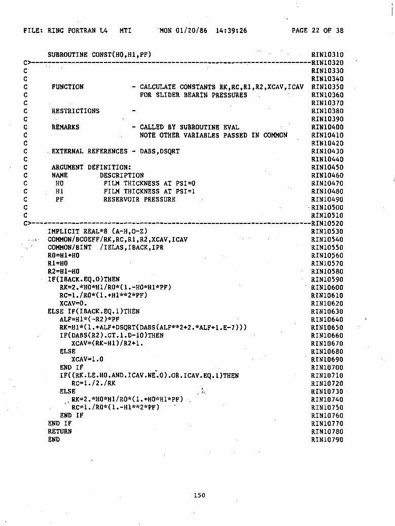
FILE: RING FORTRAN L4 MTI MON 01/20/86 14:39:26 PAGE 22 OF 38
ccccccccccccccccccc
••••»•••
SUBROUTINE CONST ( HO, H1,PF)
FUNCTION - CALCULATE CONSTANTS RK,RC,R1,R2,XCAV,ICAVFOR SLIDER BEARIN PRESSURES
RESTRICTIONS -
REMARKS - CALLED BY SUBROUTINE EVALNOTE OTHER VARIABLES PASSED IN COMMON
EXTERNAL REFERENCES - DABS,DSQRT
ARGUMENT DEFINITION:NAME DESCRIPTIONHO FILM THICKNESS AT PSI=0HI FILM THICKNESS AT PSI=1PF RESERVOIR PRESSURE
IMPLICIT REAL*8 (A-H,0-Z)COMMON/BCOEFF/RK,RC,R1,R2,XCAV,ICAVCOMMON/BINT /IELAS,IBACK,IPRRO=H1+HOR1=HOR2=H1-HOIF(IBACK.EQ.O)THEN
RK=2.*HO*H1/RO*(1.-HO*H1*PF)RC=1./RO*(1.+H1**2*PF)XCAV=0 .
ELSE IF(IBACK.EQ.1)THENALF=H1*(-R2)*PFRK=H1*( 1 .+ALF+DSQRT(DABS(ALF**2+2.*ALF+1 .E-7 ) ) )IF(DABS(R2).GT.1.D-10)THEN
XCAV=(RK-H1)/R2+1.ELSE
XCAV=1.0END IFIF((RK.LE.HO.AND.ICAV.NE".O).OR.ICAV.EQ.I)THEN
RC=l./2./RK•ELSE
, RK=2.*HO*H1/RO*(1.+HO*H1*PF)' RC=1./RO*(1.-H1**2*PF) '
END IFEND IFRETURNEND
RIN10310
RIN10330RIN10340RIN10350RIN10360RIN10370RIN10380RIN10390RIN10400RIN10410RIN10420RIN10430RIN10440RIN10450RIN10460RIN10470RIN10480RIN10490RIN10500RIN10510DTXII n^ontvlNlUJ/U
RIN10530RIN10540RIN10550RIN10$60RIN10570RIN10580RIN10590RIN10600RIN10610RIN10620RIN10630RIN10640RIN106SORIN10660RIN10670RIN10680RIN10690RIN10700RIN10710RIN10720RIN10730RIN10740RIN10750RIN10760RIN10770RIN10780RIN10790
150

FILE: RING FORTRAN L4 MTI MON 01/20/86 14:39:26 PAGE 23 OF 38
CCCCC
C
C
10
20
C
SUBROUTINE CONST2(HO,H1,PF)
REMARKS - SEE CONST
IMPLICIT REAL*8 (A-H,0-Z)COMMON/BCD /XLOC(100),C(100) ,D(100),NDX(3),NDP(3),DX(3) ,DP(3)COMMON/BCOEFF/RK,RC,R1,R2,XCAV,ICAVCOMMON/ BINT /IELAS,IBACK,IPRRO=H1+HOR1=HOR2=H1-HOCTEMP=(-1 )**( IBACK+1 )RK=2.*HO*H1/RO*(1.+CTEMP*HO*H1*PF)RC=1 . /R0*( 1 .-CTEMP*H1**2*PF )XCAV=0.IF(IBACK.EQ.1)THEN
IF(IPR.EQ.1)WRITE(4,*)' 'PMIN=100.DO 10 I=1,NDP(2)+NDP(3)
IF(IPR.EQ.1)WRITE(4,*)P(XLOC(D)PMIN=DMIN1(PMIN,P(XLOC(I)))
CONTINUEIF(PMIN.GE.O.DO)RETURNH11=H1-HOXCAV=0.5HCAV=H1+H11*(XCAV-1.)ICOUNT=0ICOUNT=ICOUNT+1HCVOLD=HCAVFHCAV=PF+1 . /Hll*(-l . /Hl+HCAV/2 . /Hl**2+l . /2 . /HCAV)F1HCAV=1 . /Hll*( 1 . 12 . /Hl**2-l . /2 . /HCAV**2 )HCAV=HCAV-FHCAV/ F 1HCAVXCAV=(HCAV-H1)/H11+1.IF(IPR.EQ.1)WRITE(4,*)XCAVIF(ICOUNT.LT.10.AND.DABS(HCAV-HCVOLD).GT.1.D-7)GOTO 20RK=HCAVRC=l./2./HCAV
END IFRETURNEND
RIN10800
RIN10820RIN10830RIN10840RIN10850RIN10860
RIN10880RIN10890RIN10900RIN10910RIN10920RIN10930RIN10940RIN10950RIN10960RIN10970RIN10980RIN10990RIN11000RIN11010RIN11020RIN11030RIN11040RIN11050RIN11060RIN11070RIN11080RIN11090RIN11100RIN11110RIN11120RIN11130RIN11140RIN11150RIN11160RIN11170RIN11180RIN11190RIN11200RIN11210RIN11220RIN11230
151

FILE: RING FORTRAN LA MTI MON 01/20/86 14:39:26 PAGE 24 OF 38
cccccccccccccccccc
SUBROUTINE DFN1(X,Y,D)
FUNCTION - DERIVATIVE ROUTINE USED BY RUK(NO HYDRODYNAMICS)
RESTRICTIONS
REMARKS - NOTE VARIABLES PASSED IN COMMON
EXTERNAL REFERENCES -
ARGUMENT DEFINITION:NAME DESCRIPTIONX VALUE OF X FOR DERIVATIVESY VALUES OF INDEPENDENT VARIABLESD VALUES OF DERIVATIVES
IMPLICIT REAL*8 (A-H,0-Z)DIMENSION Y(4),D(4)COMMON/BPAR /AL,BET,PO,EPS,PF,S,U,DTD(1)=Y(2)D(2)=Y(3)D(3)=Y(4)D(4)=-Y(1)/ALRETURNEND
RIN11240_— — __— DTM1 1 9<»n
RIN11260RIN11270RIN11280RIN11290RIN11300RIN11310RIN11320RIN11330RIN11340RIN11350RIN11360RIN11370RIN11380RIN11390RIN11400RIN11410RIN11420RIN11430
RIN11450RIN11460RIN11470RIN11480RIN11490RIN11500RIN11510RIN11520RIN11530
152

FILE: RING FORTRAN L4 MON 01/20/86 14:39:26 PAGE 25 OF 38
cccccccccccccccccc
SUBROUTINE DFN2(X,Y,D)
FUNCTION - DERIVATIVE ROUTINE USED BY RUK(HYDRODYNAMICS INCLUDED)
RESTRICTIONS
REMARKS - NOTE VARIABLES PASSED IN COMMON
EXTERNAL REFERENCES - P
ARGUMENT DEFINITION:NAME DESCRIPTIONX VALUE OF X FOR DERIVATIVESY VALUES OF INDEPENDENT VARIABLESD VALUES OF DERIVATIVES
IMPLICIT REAL*8 (A-H,0-Z)DIMENSION Y(4),D(4)COMMON/BPAR /AL,BET,PO,EPS,PF,S,U,DTCOMMON /BFLAG /IFLAG,IPLOADD(1)=Y(2)D(2)=Y(3)D(3)=Y(4)H=0IF(IPLOAD.EQ.1)H=POIF(X.GT.O.)H=H-P(X)H=H*BETD(4)=(H-Y(1))/ALRETURNEND
RIN11540
RIN11560RIN11570RIN11580RIN11590RIN11600RIN11610RIN11620RIN11630RIN11640RIN11650RIN11660RIN11670RIN11680RIN11690RIN11700RIN11710RIN11720RIN11730
RIN11750RIN11760RIN11770RIN11780RIN11790RIN11800RIN11810RIN11820RIN11830RIN11840RIN11850RIN11860RIN11870RIN11880
153

FILE: RING FORTRAN L4 MTI MON 01/20/86 14:39:26 PAGE 26 OF 38
ccccc ,ccccccccccccc
SUBROUTINE DFN3(X,Y,D)
FUNCTION - DERIVATIVE ROUTINE USED BY RUK(HYDRODYNAMICS INCLUDED, NO PRELOAD PO)
. • ' . . • 'RESTRICTIONS ' -
REMARKS - NOTE VARIABLES PASSED IN COMMON
EXTERNAL REFERENCES - P
ARGUMENT DEFINITION:NAME DESCRIPTIONX VALUE OF X FOR DERIVATIVESY VALUES OF INDEPENDENT VARIABLESD VALUES OF DERIVATIVES
IMPLICIT REAL*8 (A-H,0-Z)DIMENSION Y(4),D(4)COMMON/BPAR /AL,BET,PO,EPS,PF,S,U,DTCOMMON/BINT /IELAS,IBACK,IPRD(1)=Y(2)D(2)=Y(3)D(3)=Y(4)H=BET*POD(4)=(H-Y(1))/ALRETURNEND
RIN11890
RIN11910RIN11920RIN11930RIN11940RIN11950RIN11960RIN11970RIN11980RIN11990RIN12000RIN12010RIN12020RIN12030RIN12040RIN12050RIN12060RIN12070RIN12080
RIN12100RIN12110RIN12120RIN12130RIN12140RIN12150RIN12160RIN12170RIN12180RIN12190RIN12200
154

FILE: RING FORTRAN L4 MTI MON 01/20/86 14:39:26 PAGE 27 OF 38
SUBROUTINE ELAS RIN12210
^cccccccccccccr*L*
1009
600
FUNCTION - DETERMINE ELASTIC SOLUTION(NO HYDRODYNAMICS)HELAS , HI ELAS , H2ELAS ,H3ELAS , FORCE
RESTRICTIONS•
REMARKS - NOTE VARIABLES PASSED IN COMMON
EXTERNAL REFERENCES - NONE
IMPLICIT REAL*8 (A-H.O-Z)DIMENSION Y0(4)COMMON/ BPAR /AL,BET,PO,EPS,PFCOMMON/BCD /XLOC(IOO) ,C(100) ,D(100) ,NDX(3) ,NDP(3) ,DX(3) ,DP(3)COMMON/BELAS /FORCE, HELAS, H1ELAS,H2ELAS, H3ELAS, Wl(4) ,W2(4)COMMON/BFLAG /IFLAG,IPLOADY0(l)=0.Y0(2)=0.Y0(3)=0.Y0(4)=0.WRITE(6,1009)FORMAT(5X,1HX,8X,1HH,9X,2HH' ,7X,3HH' ' ,7X,4HH' ' ' ,6X,4HPRES$,8X,5HFORCE)IFUFLAG.EQ.DTHEN
IMIN=NDP(2)+1IMAX=NDP(2)+NDP(3)
ELSE IF(IFLAG.EQ.2)THENIMIN=1IMAX=NDP(2)
ELSE IF(IFLAG.EQ.3)THENIMIN=1IMAX=NDP(2)+NDP(3)
ELSE IF(IFLAG.EQ.4)THENIMIN=1IMAX=NDP(1)+NDP(2)
END IFDO 600 I=IMIN,IMAX
YO(1)=YO(1)+C(I)YO(2)=YO(2)+D(I)
CONTINUEYO(1)=YO(1)*PO*BETYO(2)=YO(2)*PO*BETHELAS=1.-YO(1)H1ELAS=-YO(2)H2ELAS=-YO(3)H3ELAS=-YO(4)WRITE(6,'(F8.4,5F10.5,F13.5 )')!., HELAS, H1ELAS,H2ELAS,H3ELAS,0. ,0.FORCE=O.DOIF(YO(1).GT.1.)THEN
-KIWI^ZURIN12230RIN12240RIN12250RIN12260RIN12270RIN12280RIN12290RIN12300RIN12310RIN12320RIN12330RIN12340RIN12350DTXI1 O^&HKlnl£ ODD
RIN12370RIN12380RIN12390RIN12400RIN12410RIN12420RIN12430•RIN12440RIN12450RIN12460RIN12470RIN12480RIN12490RIN12500RIN12510RIN12520RIN12530RIN12540RIN12550RIN12560RIN12570RIN12580RIN12590RIN12600RIN12610RIN12620RIN12630RIN12640RIN12650RIN12660RIN12670RIN12680RIN12690RIN12700RIN12710RIN12720RIN12730RIN12740RIN12750
155
FILE: RING FORTRAN LA MTI MON 01/20/86 14:39:26 PAGE 28 OF 38
ccccccccccccccc
CHI=YO(1)-1.0Y0(l)=1.0B=CHI/(W2(3)*W1(1)/W1(3)-W2(D)A=-B*W2(3)/W1(3)YO(2)=A*W1(2)+B*W2(2)+YO(2)Y0(3)=0.YO(4)=A*W1(4)+B*W2(4)FORCE=YO(4)*AL/BETHELAS=1.0-YO(1)H1ELAS=-YO(2)H2ELAS=-YO(3)H3ELAS=-YO(4)WRITE(6,'(F8.4,5F10.5,F13.5)')1.0,HELAS,H1ELAS,H2ELAS
$ ,H3ELAS,0., FORCEEND IFRETURNEND
SUBROUTINE ERRMSG
FUNCTION - PRINT ERROR TERMS UPON EXIT FROM *ZSCNT*
RESTRICTIONS - CALLED ONLY IF IER.NE.O FROM *ZSCNT*•
REMARKS - FINAL VALUES OF X AND F FROM EVALARE PRINTED
INPUT/OUTPUT:UNIT DESCRIPTION4 TERMINAL OUTPUT6 OUTPUT FILE
IMPLICIT REAL*8 (A-H,0-Z)COMMON/BLAST /X1,X2,F1,F2WRITE(4,'(8X,"W(1)",10X,"W(2)",10X,"F(1)",10X,"F(2)"+ ,/)')WRITE(4,'(1X,4(2X,E12.5))')X1,X2,F1,F2WRITE(6,I(8X,"W(1)",10X,"W(2)",10X,"F(1)",10X,"F(2)"+ )')WRITE(6,'(1X,4(2X,E12.5))')X1,X2,F1,F2RETURNEND
RIN12760RIN12770RIN12780RIN12790RIN12800RIN12810RIN12820RIN12830RIN12840RIN12850RIN12860RIN12870RIN12880RIN12890RIN12900RIN12910RIN12920
RIN12930
RIN12950RIN12960RIN12970RIN12980RIN12990RIN13000RIN13010RIN13020RIN13030RIN13040RIN13050RIN13060RIN13070RIN13080RIN13090
RIN13110RIN13120RIN13130RIN13140RIN13150RIN13160RIN13170RIN13180RIN13190RIN13200
156
FILE:
CCCCCCCCCCCCCCCCCCCCC("•
5
7
RING FORTRAN L4 MTI MON 01/20/86 14:39:26 PAGE
SUBROUTINE EVAL(X,F,N,PAR)
FUNCTION - DEFINES EQUATIONS FOR H AND H1 WHICH ARESOLVED BY SECANT METHOD *ZSCNT*
RESTRICTIONS
REMARKS - NOTE VARIABLE PASSED IN COMMON
EXTERNAL REFERENCES - CONST
INPUT/OUTPUT:UNIT DESCRIPTION
ARGUMENT DEFINITION:NAME DESCRIPTIONX X(l) IS DISPLACEMENT AT 1
X(2) IS X1 AT 1F EQUATIONS (2) FOR H AND H1
N NO. OF EQUATIONS (N=2)PAR NOT USED
IMPLICIT REAL*8 (A-H,0-Z)DIMENSION X(N),F(N),PAR(1)COMMON/BPAR /AL,BET,PO,EPS,PFCOMMON/BCD /XLOC(100),C(100),D(100),NDX(3) ,NDP(3),DX(3) ,DP(3)COMMON/BCOEFF/RK,RC,R1,R2,XCAV,ICAVCOMMON/BINT /IELAS,IBACK, IPRCOMMON/BLAST /X1LAST,X2LAST,F1LAST,F2LASTCOMMON/BPROF /ClCOMMON/BFLAG /IFLAG.IPLOADH1=1.0-X(1)H11=C1-X(2)HO=H1-H11CALL CONST(HO,H1,PF)SUM1=X(1)SUM2=X(2)INDEX=0CONTINUEINDEX=INDEX+1IF(IFLAG.EQ.1.AND.INDEX.GT.NDP(2)+NDP(3))GOTO 6IF(IFLAG.EQ.2.AND.INDEX.GT.NDP(2))GOTO 6IF(XLOC( INDEX). LT.DMIN1U. -EPS, XCAV))GOTO 5IF(XLOC(INDEX).LT.XCAV)THEN
PRES=0ELSE
PRES=P(XLOC( INDEX))END IFIF(XLOC( INDEX). GT.l. -EPS) PRES=PRES-POCONTINUESUM1=SUM1+C( INDEX )*PRES*BET
157
29 OF 38
RIN13210D T \T 1 1 O 1 O-RIN13Z20RIN13230RIN13240RIN13250RIN13260RIN13270RIN13280RIN13290RIN13300RIN13310RIN13320RIN13330RIN13340RIN13350RIN13360RIN13370RIN13380RIN13390RIN13400RIN13410RIN13420RIN13430RIN13440RIN13450DTXI1 *1 / £.n•RIN1 J460RIN13470RIN13480RIN13490RIN13500RIN13510RIN13520RIN13530RIN13540RIN13550RIN13560RIN13570RIN13580RIN13590RIN13600RIN13610RIN13620RIN13630RIN13640RIN13650RIN13660RIN13670RIN13680RIN13690RIN13700RIN13710RIN13720RIN13730RIN13740RIN13750
FILE: RING FORTRAN L4 MTI MON 01/20/86 14:39:26 PAGE 30 OF 38
SUM2=SUM2+D(INDEX)*PRES*BET RIN13760GOTO 5 RIN13770
6 CONTINUE RIN13780F(1)=SUM1 RIN13790F(2)=SUM2 , RIN13800X1LAST=X(1) r • •-• RIN13810X2LAST=X(2) RIN13820F1LAST=F(1) RIN13830F2LAST=F(2) RIN13840RETURN . RIN13850END . RIN13860
158

FILE: RING FORTRAN L4 MTI MON 01/20/86 14:39:26 PAGE 31 OF 38
ccccccccccccccccccccccc
5
7
SUBROUTINE EVAL3(X,F,N,PAR)
FUNCTION - DEFINES EQUATIONS FOR H AND H1 WHICH ARESOLVED BY SECANT METHOD *ZSCNT*
RESTRICTIONS
REMARKS - NOTE VARIABLE PASSED IN COMMON
EXTERNAL REFERENCES - CONST
INPUT/OUTPUT:UNIT DESCRIPTION
ARGUMENT DEFINITION:NAME DESCRIPTIONX X(l) IS DISPLACEMENT AT 1
X(2) IS X' AT 1F EQUATIONS (2) FOR H AND H1
N NO. OF EQUATIONS (N=2)PAR NOT USED
IMPLICIT REAL*8 (A-H,0-Z)DIMENSION X(N),F(N),PAR(1)COMMON/ BPAR /AL,BET,PO,EPS,PFCOMMON/BCD /XLOC(100),C(100) ,D(100),NDX(3),NDP(3),DX(3),DP(3)COMMON/ BCOEFF/RK,RC,R1,R2,XCAV, I CAVCOMMON/BINT /IELAS,IBACK,IPRCOMMON/ BLAST /X1LAST,X2LAST,F1LAST,F2LASTCOMMON/ BPROF /ClCOMMON/ BFLAG /IFLAG,IPLOADH1=1.0-X(1)H11=C1-X(2)HO=H1-H11CALL CONST ( HO, H1,PF)SUM1=X(1)SUM2=X(2)INDEX=0CONTINUEINDEX=INDEX+1IF(INDEX.GT.NDP(2)+NDP(3))GOTO 6IF(XLOC(INDEX).LT.DMIN1(1.-EPS,XCAV))GOTO 5IF(XLOC( INDEX) .LT.XCAV)THEN
PRES=0ELSE
PRES=P(XLOC( INDEX))END IFPRES=PRES-POCONTINUESUM1=SUM1+C(INDEX)*PRES*BETSUM2=SUM2+D( INDEX)*PRES*BET
159
RIN13870
RIN13890RIN13900RIN13910RIN13920RIN13930RIN13940RIN13950RIN13960RIN13970RIN13980RIN13990RIN14000RIN14010RIN14020RIN14030RIN14040RIN14050RIN14060RIN14070RIN14080RIN14090RIN14100RIN14110
RIN14130RIN14140RIN14150RIN14160RIN14170RIN14180RIN14190RIN14200RIN14210RIN14220RIN14230RIN14240RIN14250RIN14260RIN14270RIN14280RIN14290RIN14300RIN14310RIN14320RIN14330RIN14340RIN14350RIN14360RIN14370RIN14380RIN14390RIN14400RIN14410

FILE: RING FORTRAN L4 MTI MON 01/20/86 14:39:26 PAGE 32 OF 38
GOTO 5 RIN14420CONTINUE RIN14430F(1)=SUM1 RIN14440F(2)=SUM2 RIN14450X1LAST=X(1) RIN14460X2LAST=X(2) . RIN14470F1LAST=F(1) RIN14480F2LAST=F(2) RIN14490RETURN RIN14500END RIN14510
160

FILE: RING FORTRAN L4 MTI MON 01/20/86 14:39:26 PAGE 33 OF 38
ccccccccccccccccccccccc
5
7
SUBROUTINE EVAL4(X,F,N,PAR)
FUNCTION - DEFINES EQUATIONS FOR H AND H1 WHICH ARESOLVED BY SECANT METHOD *ZSCNT*
RESTRICTIONS
REMARKS - NOTE VARIABLE PASSED IN COMMON
EXTERNAL REFERENCES - CONST
INPUT/OUTPUT:UNIT DESCRIPTION
ARGUMENT DEFINITION:NAME DESCRIPTIONX X(l) IS DISPLACEMENT AT 1
X(2) IS X1 AT 1F EQUATIONS (2) FOR H AND H1
N NO. OF EQUATIONS (N=2)PAR NOT USED
IMPLICIT REAL*8 (A-H,0-Z)DIMENSION X(N),F(N),PAR(1)COMMON/ BPAR /AL,BET,PO,EPS,PFCOMMON/BCD /XLOC(100),C(100) ,D(100),NDX(3) ,NDP(3),DX(3) ,DP(3)COMMON/BCOEFF/RK,RC,R1,R2,XCAV,ICAVCOMMON/BINT /IELAS,IBACK,IPRCOMMON/BLAST /X1LAST,X2LAST,F1LAST,F2LASTCOMMON/ BPROF /ClCOMMON/ BFLAG /IFLAG,IPLOADH1=1.0-X(1)H11=C1-X(2)HO=H1-H11CALL CONST(HO,H1,PF)SUM1=X(1)SUM2=X(2)INDEX=0CONTINUEINDEX=INDEX+1IF(INDEX.GT.NDP(1)+NDP(2))GOTO 6IF(XLOC(INDEX).LT.DMIN1(1.-EPS,XCAV))GOTO 5 'IF(XLOC( INDEX). LT.XCAV)THEN
PRES=0ELSE
PRES=P(XLOC( INDEX))END IFPRES=PRES-POCONTINUESUM1=SUM1+C(INDEX)*PRES*BETSUM2=SUM2+D( INDEX)*PRES*BET
161
RIN14520
RIN14540RIN14550RIN14560RIN14570RIN14580RIN14590RIN14600RIN14610RIN14620RIN14630RIN14640RIN14650RIN14660RIN14670RIN14680RIN14690.RIN14700'RIN14710RIN14720RIN14730RIN14740RIN14750RIN14760
RIN14780RIN14790RIN14800RIN14810RIN14820RIN14830RIN14840RIN14850RIN14860RIN14870RIN14880RIN14890RIN14900RIN14910RIN14920RIN14930RIN14940RIN14950RIN14960RIN14970RIN14980RIN14990RIN15000RIN15010RIN15020RIN15030RIN15040RIN15050RIN15060

FILE: RING FORTRAN L4 MTI MON 01/20/86 14:39:26 PAGE 34 OF 38
6
CCCCCCCCCCCCCCC
GOTO 5CONTINUEF(1)=SUM1F(2)=SUM2X1LAST=X(1)X2LAST=X(2)F1LAST=F(1)F2LAST=F(2)RETURNEND
FUNCTION P(PSI)
FUNCTION - RETURN HYDRODYNAMIC PRESSURE AT PSI
RESTRICTIONS
REMARKS - NOTE VARIABLES PASSED IN COMMON
EXTERNAL REFERENCES - DABS
ARGUMENT DEFINITION:NAME DESCRIPTIONPSI ... VALUE OF X WHERE PRESSURE IS DESIRED
IMPLICIT REAL*8 (A-H,0-Z)COMMON/BCOEFF/RK,RC,R1,R2,XCAV,ICAVCOMMON/BINT /IELAS,IBACK,IPRH«R1+R2*PSIHINV=1./HP=0.IF(PSI.GE.XCAV.AND.DABS(R2).GT.1.D-10)THEN
P=1./R2*(HINV*(-1.+RK/2.*HINV)+RC)END IFIF(IBACK.EQ.1)THEN
P=-PEND IFRETURNEND
RIN15070RIN15080RIN15090RIN15100RIN15110RIN15120RIN15130RIN15140RIN15150RIN15160
RIN15170
RIN15190RIN15200RIN15210RIN15220RINI5230RIN15240RIN15250RIN15260RIN15270RIN15280RIN15290RIN15300RIN15310RIN15320RIN15330
____D TM 1 I/, n
RIN15350RIN15360RIN15370RIN15380RIN15390RIN15400
' RIN15410RIN15420RIN15430RIN15440RIN15450RIN15460RIN15470RIN15480
162
FILE: RING FORTRAN L4 MTI MON 01/20/86 14:39:26 PAGE 35 OF 38
cccccccccccccccccccccc
5
SUBROUTINE PRT(X,Y, ITERM)
FUNCTION - USING DISPLACEMENTS, CONVERT TO FILMTHICKNESSES AND PRINT OUT
RESTRICTIONS
REMARKS
EXTERNAL REFERENCES - P
INPUT/OUTPUT:UNIT DESCRIPTIONITERM OUTPUT UNIT . . . . . .
ARGUMENT DEFINITION:NAME DESCRIPTIONX DIMENSIONLESS LENGTH VARIABLE ,Y DISPLACEMENT AND ITS DERIVATIVESITERM OUTPUT UNIT
IMPLICIT REAL*8 (A-H,0-Z) - : '''.''"COMMON/BINT /IELAS,IBACK,IPRCOMMON/BPROF /ClDIMENSION Y(4) , t
H=1.-Y(1)+C1*(X-1.)H1=C1-Y(2) ..,.',. , '.'.'.. . ,H2=-Y(3) . . : . '"' :H3=-Y(4) !. """PRES=0 .IF(IELAS.EQ.O.AND.X.GE.O.)PRES=P(X)WRITE(ITERM,5)X,H,H1,H2,H3,PRES . .. : . ......FORMAT(F10.4,5F12.5) ', • 1 T. "RETURNE N D . . . . . .
RIN15490
RIN15510RIN15520RIN15530RIN15540RIN15550RIN15560RIN15570RIN15580RIN15590RIN15600RIN15610RIN15620RIN15630RIN15640RIN15650RIN15660RIN15670RIN15680RIN15690RIN15700RIN15710RIN15720
RIN15740RIN15750RIN15760RIN15770RIN15780RIN15790RIN15800RIN15810RIN15820RIN15830RIN15840RIN15850RIN15860RIN15870
163

FILE: RING FORTRAN L4 MTI MON 01/20/86 14:39:26 PAGE 36 OF 38
ccccccccccccccccccc
c
SUBROUTINE PRTOUT(XX)
FUNCTION - PRINT FILM THICK., PRES., ETC.
RESTRICTIONS
REMARKS - NOTE VARIABLES PASSED IN COMMON
EXTERNAL REFERENCES - DFN1,DFN2,DFN3,PRT,RUK
INPUT/OUTPUT:UNIT DESCRIPTION6 OUTPUT FILE
ARGUMENT DEFINITION:NAME DESCRIPTIONXX(2) DISPLACEMENT, SLOPE OF DISPLACEMENT
IMPLICIT REAL*8 (A-H.O-Z)COMMON/BINT /IELAS,IBACK,IPRCOMMON/BELAS /FORCE, HELAS, HlELAS, H2ELAS, H3ELAS, Wl(4) ,W2(4)COMMON/BCD /XLOC(IOO) ,C(100),D(100),NDX(3) ,NDP(3) ,DX(3) ,DP(3)COMMON/ BFLAG / I FLAG , I PLOADDIMENSION XX(2),YO(4),YT(4),DJ(4),CKJ(4,4)EXTERNAL DFN 1 , DFN2 , DFN3
XNN=1.0YO(1)=XX(DYO(2)=XX(2)Y0(3)=0.Y0(4)=0.IF(IBACK.EQ. LAND. FORCE. GT.1.D-8)THEN
WRITE(6,1009)WRITE(6,'(F8.4,5F10.5,F13.5)')1.0, HELAS, HlELAS, H2ELAS
$ ,H3ELAS,0., FORCERETURNELSE
WRITE(6,1007)IF(IPR.EQ.1)THEN
WRITE(6, '("<§")')ELSE
WRITE(6,'(" ")')END IFCALL PRT(XNN,YO,6)
END IFIF(IPR.EQ.1)THEN
IF(IFLAG.EQ.2.0R.IFLAG.EQ.4)GOTO 111IPLOAD=1CALL RUK(-DX(3)/2.,-DP(3)/2.,XNN,XNN,YO,YO,4,DFN2,YT,DJ,CKJ,4i),CALL PRT(XNN,YO,6)DO 9 JJ=2,NDP(3)
164
RIN15880OTMl ftQ("\"KIWI JO7\J
RIN15900RIN15910RIN15920RIN15930RIN15940RIN15950RIN15960RIN15970RIN15980RIN15990RIN16000RIN16010RIN16020RIN16030RIN16040RIN16050RIN16060RIN16070RIN16080D TMI £nonKINlouyuRIN16100RIN16110RIN16120RIN16130RIN16140RIN16150RIN16160RIN16170RIN16180RIN16190RIN16200RIN16210RIN16220RIN16230RIN16240RIN16250RIN16260RIN16270RIN16280RIN16290RIN16300RIN16310RIN16320RIN16330RIN16340RIN16350RIN16360RIN16370RIN16380RIN16390RIN16400RIN16410RIN16420
FILE: RING FORTRAN L4 MTI MON 01/20/86 14:39:26 PAGE 37 OF 38
J=NDP(3)+1-JJ RIN16430CALL RUK(-DX(3),-DP(3),XNN,XNN,YO,YO,4,DFN2,YT,DJ,CKJ,4) RIN16440CALL PRT(XNN,YO,6) RIN16450
9 CONTINUE RIN16460CALL RUK(-DX(3)/2.,-DP(3)/2.,XNN,XNN,YO,YO,4,DFN2,YT,DJ,CKJ,4) RIN16470CALL PRT(XNN,YO,6) RIN16480
111 CONTINUE RIN16490IF(IFLAG.EQ.1)THEN RIN16500
IPLOAD=0 RIN16510ELSE IF(IFLAG.EQ.2)THEN RIN16520
IPLOAD=1 RIN16530ELSE IF(IFLAG.EQ.3)THEN RIN16540
IPLOAD=1 RIN16550ELSE IF(IFLAG.EQ.4)THEN RIN16560
IPLOAD=1 RIN16570END IF RIN16580CALL RUK(-DX(2)/2.,-DP(2)/2.,XNN,XNN,YO,YO,4,DFN2,YT,DJ,CKJ,4) RIN16590CALL PRT(XNN,YO,6) RIN16600DO 8 JJ=2,NDP(2) RIN16610J=NDP(2)+1-JJ RIN16620CALL RUK(-DX(2),-DP(2),XNN,XNN,YO,YO,4,DFN2,YT,DJ,CKJ,4) RIN16630CALL PRT(XNN,YO,6) RIN16640
8 CONTINUE RIN16650CALL RUK(-DX(2)/2.,-DP(2)/2.,XNN,XNN,YO,YO,4,DFN2,YT,DJ,CKJ,4) RIN16660CALL PRT(XNN,YO,6) RIN16670IF(IFLAG.EQ.1.0R.IFLAG.EQ.2)THEN RIN16680
WRITE(6,'("(§'')') RIN16690RETURN RIN16700
END IF RIN16710DO 7 J=1,NDP(1) RIN16720IF(IFLAG.EQ.4)THEN RIN16730
CALL RUK(-DX(1),-DP(1),XNN,XNN,YO,YO,4,DFN3,YT,DJ,CKJ,4) RIN16740ELSE RIN16750
CALL RUK(-DX(1),-DP(1),XNN,XNN,YO,YO,4,DFN1,YT,DJ,CKJ,4) RIN16760END IF RIN16770CALL PRT(XNN,YO,6) RIN16780
7 CONTINUE RIN16790END IF RIN16800WRITE(6,'("<a")') RIN16810RETURN RIN16820
C . RIN168301007 FORMAT(7X,1HX,10X,1HH,11X,2HH',9X,3HH'',9X,4HH''',8X,4HPRES) RIN168401009 FORMAT(5X,1HX,8X,1HH,9X,2HH',7X,3HH'',7X,4HH''',6X,4HPRES RIN16850
$,8X,5HFORCE) RIN16860C RIN16870
END RIN16880
165
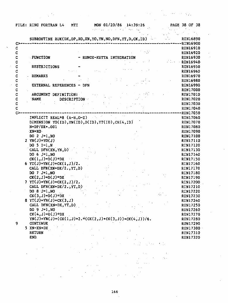
FILE: RING FORTRAN L4 MTI MON 01/20/86 14:39:26 PAGE 38 OF 38
SUBROUTINE RUK(DX,DP,XO,XN,YO,YN,NO,DFN,YT,D,CK,ID) RIN16890
Cccccccccccccc
9
'••.*.'FUNCTION - RUNGE-KUTTA INTEGRATION
RESTRICTIONS, • . • .- ' "' '.'
- REMARKSi - • ',
EXTERNAL REFERENCES - DFN . .
ARGUMENT DEFINITION: '•NAME DESCRIPTION ' •
- . • . . .
IMPLICIT REAL*8 (A-H,0-Z)DIMENSION YO(ID),YN(ID),D(ID),YT(ID),CK(4,ID) "N=DP/DX+.001XN=XODO 2 J=1,NO
2 YN(J)=YO(J)DO 5 1=1, NCALL DFN(XN,YN,D)DO 6 J=1,NOCK(1,J)=D(J)*DX
6 YT(J)=YN(J)+CK(l,J)/2.CALL DFN(XN+DX/2.,YT,D) :
DO 7 J=1,NOCK(2,J)=D(J)*DX
7 YT(J)=YN(J)+CK(2,J)/2.CALL DFN(XN+DX/2.,YT,D) 'DO 8 J=1,NOCK(3,J)=D(J)*DX
8 YT(J)=YN(J)+CK(3,J)CALL DFN(XN+DX,YT,.D) ,DO 9 J=1,NOCK(4,J)=D(J)*DX .YN(J)=YN(J)+(CK(l,J)+2.*(CK(2,J)+CK(3,J))+CK(4,J))/6.CONTINUE .
5 XN=XN+DX .RETURNEND. " . ' . . ' .
RIN16910RIN16920RIN16930
- -. RIN16940RIN16950RIN16960RIN16970RIN16980RIN16990RIN17000RIN17010RIN17020RIN17030RIN17040
RIN17060RIN17070RIN17080RIN17090RIN17100RIN17110RIN17120RIN17130RIN17140RIN17150RIN17160RIN17170RIN17180RIN17190RIN17200RIN17210RIN17220RIN17230RIN17240RIN17250RIN17260RIN17270RIN17280RrN17290RIN17300RIN17310RIN17320
166

FILE: ZSCNT FORTRAN Al IMSL FRI 06/17/83 08:20:26 PAGE 1 OF 14
cc
ccccccccccccccccccccccccccccccccccccccccccccccccccc
SUBROUTINE ZSCNT (FCN, NSIG.N, ITMAX, PAR, X, FNORM, WK, IER)IMSL ROUTINE NAME - ZSCNTTHIS PROGRAM SHOULD BE COMPILED IN FORTRAN 4 (FORTHX)
COMPUTER - IBM/DOUBLE
LATEST REVISION - JUNE 1, 1980
PURPOSE - SOLVE A SYSTEM OF NONLINEAR EQUATIONS
USAGE - CALL ZSCNT (FCN, NSIG.N, ITMAX, PAR, X, FNORM,WK.IER)
ARGUMENTS FCN - THE NAME OF A USER-SUPPLIED SUBROUTINE WHICHEVALUATES THE SYSTEM OF EQUATIONS TO BESOLVED. FCN MUST BE DECLARED EXTERNAL INTHE CALLING PROGRAM AND MUST HAVE THEFOLLOWING FORM,SUBROUTINE FCN(X,F,N,PAR)DIMENSION X(N),F(N),PAR(1)F(l)=.
F(N)=RETURNEND
GIVEN X(1)...X(N), FCN MUST EVALUATE THEFUNCTIONS F(1)...F(N) WHICH ARE TO BE MADEZERO. X SHOULD NOT BE ALTERED BY FCN. THEPARAMETERS IN VECTOR PAR (SEE ARGUMENTPAR BELOW) MAY ALSO BE USED IN THECALCULATION OF F(l) .. .F(N) .
NSIG - THE NUMBER OF DIGITS OF ACCURACY DESIREDIN THE COMPUTED ROOT (INPUT).
N - THE NUMBER OF EQUATIONS TO BE SOLVED ANDTHE NUMBER OF UNKNOWNS (INPUT).
ITMAX - THE MAXIMUM ALLOWABLE NUMBER OF ITERATIONS(INPUT).
PAR - PAR CONTAINS A PARAMETER SET WHICH ISPASSED TO THE USER SUPPLIED FUNCTION FCN.PAR MAY BE USED TO PASS ANY AUXILIARYPARAMETERS NECESSARY FOR COMPUTATION OFTHE FUNCTION FCN. (INPUT)
X - A VECTOR OF LENGTH N. (INPUT/ OUTPUT) ON INPUTX IS THE INITIAL APPROXIMATION TO THE ROOT.ON OUTPUT, X IS THE BEST APPROXIMATION TOTHE ROOT FOUND BY ZSCNT.
FNORM - ON OUTPUT, FNORM IS EQUAL TOF(l)**2+. . .F(N)**2 AT THE POINT X.
WK - WORK VECTOR OF LENGTH (N+l)*(3*N+8)IER - ERROR PARAMETER. (OUTPUT)
TERMINAL ERRORIER = 129 INDICATES THAT ZSCNT FAILED TOCONVERGE WITHIN ITMAX ITERATIONS. THEUSER MAY INCREASE ITMAX OR TRY A NEW
ZSC00010ZSC00020ZSC000307crnnnAn£oL»UUUit U
ZSC00050ZSC00060ZSC00070ZSC00080ZSC00090ZSC00100ZSC00110ZSC00120ZSC00130ZSC00140ZSC00150ZSC00160ZSC00170ZSC00180ZSC00190ZSC00200ZSC00210ZSC00220ZSC00230ZSC00240•ZSC00250ZSCOQ260ZSC00270ZSC00280ZSC00290ZSC00300ZSC00310ZSC00320ZSC00330ZSC00340ZSC00350ZSC00360ZSC00370ZSC00380ZSC00390ZSC00400ZSC00410ZSC00420ZSC00430.ZSC00440ZSC00450ZSC00460ZSC00470ZSC00480ZSC00490ZSC00500ZSC00510ZSC00520ZSC00530ZSC00540ZSC00550
167
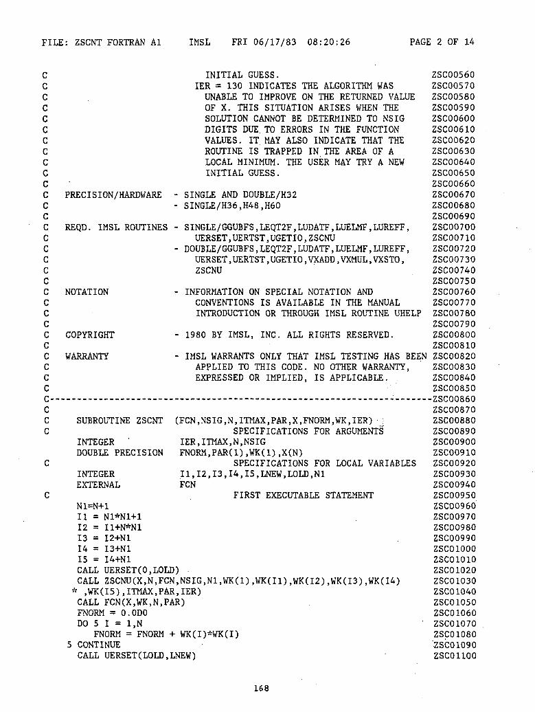
FILE: ZSCNT FORTRAN Al IMSL FRI 06/17/83 08:20:26 PAGE 2 OF 14
cccccccccccccccccccccccccccccc
ccc
c
c
INITIAL GUESS.IER = 130 INDICATES THE ALGORITHM WASUNABLE TO IMPROVE ON THE RETURNED VALUEOF X. THIS SITUATION ARISES WHEN THESOLUTION CANNOT BE DETERMINED TO NSIGDIGITS DUE. TO ERRORS IN THE FUNCTIONVALUES. IT MAY ALSO INDICATE THAT THEROUTINE IS TRAPPED IN THE AREA OF ALOCAL MINIMUM. THE USER MAY TRY A NEWINITIAL GUESS.
-
PRECISION/HARDWARE - SINGLE AND DOUBLE/H32- SINGLE/H36.H48.H60
REQD. IMSL ROUTINES - SINGLE/GGUBFS,LEQT2F,LUDATF,LUELMF,LUREFF,UERSET,UERTST,UGETIO,ZSCNU
- DOUBLE/GGUBFS , LEQT2F , LUDATF , LUELMF , LUREFF ,UERSET , UERTST , UGETIO , VXADD , VXMUL , VXSTO ,ZSCNU
NOTATION - INFORMATION ON SPECIAL NOTATION ANDCONVENTIONS IS AVAILABLE IN THE MANUALINTRODUCTION OR THROUGH IMSL ROUTINE UHELP
COPYRIGHT - 1980 BY IMSL, INC. ALL RIGHTS RESERVED.
WARRANTY - IMSL WARRANTS ONLY THAT IMSL TESTING HAS BEENAPPLIED TO THIS CODE. NO OTHER WARRANTY,EXPRESSED OR IMPLIED, IS APPLICABLE.
SUBROUTINE ZSCNT (FCN, NSIG, N.ITMAX, PAR, X, FNORM, WK, IER) ;•SPECIFICATIONS FOR ARGUMENTS
INTEGER ' IER, ITMAX,N, NSIGDOUBLE PRECISION FNORM, PAR(l) ,WK(1) ,X(N)
SPECIFICATIONS FOR LOCAL VARIABLESINTEGER I1,I2,I3,I4,I5,LNEW,LOLD,N1EXTERNAL FCN
FIRST EXECUTABLE STATEMENTN1=N+111 = N1*N1+112 = I1+N*N113 = I2+N114 = I3+N115 = I44-N1CALL UERSET (0,LOLD) .CALL ZSCNU(X,N, FCN, NSIG, N1,WK(1),WK(I1),WK(I2),WK(I3),WK(I4)* ,WK(I5),ITMAX,PAR,IER)CALL FCN(X,WK,N,PAR)FNORM = O.ODODO 5 I = l.N
FNORM = FNORM + WK(I)*WK(I)5 CONTINUECALL UERSET (LOLD.LNEW)
ZSC00560ZSC00570ZSC00580ZSC00590ZSC00600ZSC00610ZSC00620ZSC00630ZSC00640ZSC00650ZSC00660ZSC00670ZSC00680ZSC00690ZSC00700ZSC00710ZSC00720ZSC00730ZSC00740ZSC00750ZSC00760ZSC00770ZSC00780ZSC00790ZSC00800ZSC00810ZSC00820ZSC00830ZSC00840ZSC008507cr*nnft &c\•£.oL>UUoOUZSC00870ZSC00880ZSC00890ZSC00900ZSC00910ZSC00920ZSC00930ZSC00940ZSC00950ZSC00960ZSC00970ZSC00980ZSC00990ZSC01000ZSC01010ZSC01020ZSC01030ZSC01040ZSC01050ZSC01060ZSC01070ZSC01080'ZSC01090ZSC01100
168

FILE: ZSCNT FORTRAN Al IMSL FRI 06/17/83 08:20:26 PAGE 3 OF 14
IF (IER.EQ.O) GO TO 9005 ZSC011109000 CONTINUE ZSC01120
CALL UERTST(IER,6HZSCNT ) ZSC011309005 RETURN ZSC01140
END ZSC01150
FUNCTION GGUBFS (DSEED) ZSC01160DOUBLE PRECISION DSEED ZSC01170DOUBLE PRECISION D2P31M.D2P31 ZSC01180DATA D2P31M/2147483647.DO/ ZSC01190DATA D2P31 /2147483648.DO/ ZSC01200DSEED = DMOD(16807.DO*DSEED,D2P31M) ZSC01210GGUBFS = DSEED / D2P31 ZSC01220RETURN . ZSC01230END ZSC01240
169

FILE: ZSCNT FORTRAN Al IMSL FRI 06/17/83 08:20:26 PAGE 4 OF 14
SUBROUTINE LEQT2F (A,M,N,IA,B,IDGT,WKAREA,IER) ZSC01250DIMENSION A(IA,1),B(IA,1),WKAREA(1) . ZSC01260DOUBLE PRECISION A,B,WKAREA,D1,D2,WA ZSC01270IER=0 ZSC01280JER=0 ZSC01290j = N*N+1 . ZSC01300K = J+N ~ ZSG01310MM = K+N ZSC01320KK = 0 ZSC01330MM1 = MM-1 ZSC01340JJ=1 ZSC01350DO 5 L=1,N ZSC01360
DO 5 1=1,N ZSC01370WKAREA(JJ)=A(I,L) ZSC01380JJ=JJ+1 ZSC01390
5 CONTINUE ZSC01400CALL LUDATF (WKAREA(l),A,N,N,IDGT,D1)D2,WKAREA(J),WKAREA(K), ZSC014101 WA.IER) ZSC01420IF (IER.GT.128) GO TO 25 ZSC01430IF (IDGT .EQ. 0 .OR. IER .NE. 0) KK = 1 ZSC01440DO 15 I = 1,M ZSC01450
CAL'L LUELMF (A,B(I,I),WKAREA(J),N,N,WKAREA(MM)) zscoueoIF (KK .NE. 0) ZSC01470
* CALL LUREFF (WKAREA(l),B(1,I),A,WKAREA(J),N,N,WKAREA(MM),IDGT, ZSC01480* WKAREA(K),WKAREA(K),JER) ZSC01490
DO 10 11=1,N ZSC01500B(II,I) = WKAREA(MM1+II) ZSC01510
10 CONTINUE ZSC01520IF (JER.NE.O) GO TO 20 ZSC01530
15 CONTINUE ZSC01540GO TO 25 ZSC01550
20 IER = 131 ZSC0156025 JJ=1 ZSC01570
DO 30 J = 1,N ZSC01580DO 30 I = 1,N ZSC01590
A(I,J)=WKAREA(JJ) ZSC01600JJ=JJ+1 ZSC01610
30 CONTINUE - ZSC01620IF (IER .EQ. 0) GO TO 9005 ZSC01630
9000 CONTINUE • ZSC01640CALL UERTST (IER,6HLEQT2F) ZSC01650
9005 RETURN ZSC01660' END ZSC01670
170
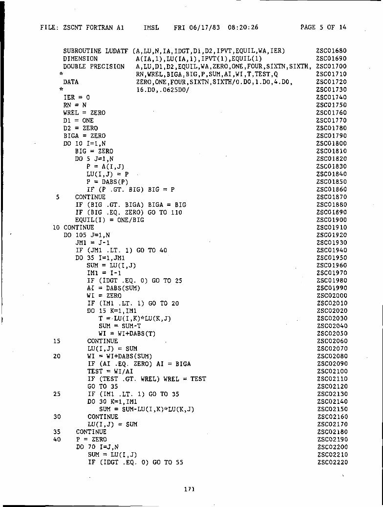
FILE: ZSCNT FORTRAN Al IMSL FRI 06/17/83 08:20:26 PAGE 5 OF 14
SUBROUTINE LUDATF (A,LU,N,IA,IDGT,D1,D2,IPVT,EQUIL,WA,IER)DIMENSIONDOUBLE PRECISION
v
DATA
A(IA,1),LU(IA,1),IPVT(1),EQUIL(1)A,LU,D1,D2,EQUIL,WA,ZERO,ONE,FOUR,SIXTN,SIXTH,RN,WREL,BIGA,BIG,P,SUM,AI,WI,T,TEST,QZERO,ONE,FOUR,SIXTN,SIXTH/0.DO,1.DO,4.DO,
* 16.DO,.0625DO/IER = 0RN = NWREL = ZERODl = ONED2 = ZEROBIGA = ZERODO 10 1=1,N
BIG = ZERODO 5 J=1,N
P = A(I,J)LU(I,J) = PP = DABS(P)IF (P .GT. BIG) BIG = P
5 CONTINUEIF (BIG .GT. BIGA) BIGA = BIGIF (BIG .EQ. ZERO) GO TO 110EQUIL(I) = ONE/BIG
10 CONTINUEDO 105 J=1,N
JM1 = J-lIF (JM1 .LT. 1) GO TO 40DO 35 I=1,JM1
SUM = LU(I,J)IM1 = 1-1IF (IDGT .EQ. 0) GO TO 25A-I = DABS (SUM)
= ZERO(IM1 .LT. 1) GO TO 2015 K=1,IM1T ='LU(I,K)*LU(K,J)SUM = SUM-TWI = WH-DABS(T)
CONTINUELU(I,J) = SUMWI = WI+DABS(SUM)IF (AI .EQ. ZERO) AI = BIGATEST = WI/AIIF (TEST .GT. WREL) WREL = TESTGO TO 35IF (IM1 .LT. 1) GO TO 35DO 30 K=1,IM1
SUM = SUM-LU(I,K)*LU(K,J)CONTINUE
SUM
WIIFDO
15
20
25
30LU(I.J) =
35 CONTINUE40 P = ZERO
DO 70 I=J,NSUM = LU(I.J)IF (IDGT .EQ. 0) GO TO 55
ZSC01680ZSC01690ZSC01700ZSC01710ZSC01720ZSC01730ZSC01740ZSC01750ZSC01760ZSC01770ZSC01780ZSC01790ZSC01800ZSC01810ZSC01820ZSC01830ZSC01840ZSC01850ZSC01860ZSC01870ZSC01880ZSC01890ZSC01900ZSC01910ZSC01920ZSC01930ZSC01940ZSC01950ZSC01960ZSC01970ZSC01980ZSC01990ZSC02000ZSC02010ZSC02020ZSC02030ZSC02040ZSC02050ZSC02060ZSC02070ZSC02080ZSC02090ZSC02100ZSC02110ZSC02120ZSC02130ZSC02140ZSC02150ZSC02160ZSC02170ZSC02180ZSC02190ZSC02200ZSC02210ZSC02220
171

FILE: ZSCNt FORTRAN Al IMSL FRI 06/17/83 08:20:26 PAGE 6 OF 14
.EQ. RN) GO TO 110IMAX) GO TO 80
AI = DABS(SUM)WI = ZEROIF (JM1 .LT. 1) GO TO 50DO 45 K=1,JM1
T = LU(I,K)*LU(K,J)SUM = SUM-TWI = WI+DABS(T)
45 CONTINUELU(I,J) = SUM
50 WI = WI-t-DABS(SUM)IF (AI .EQ. ZERO) AI = BIGATEST = WI/AIIF (TEST .GT. WREL) WREL = TESTGO TO 65
55 IF (JM1 .LT. 1) GO TO 65DO 60 K=1,JM1
SUM = SUM-LU(I,K)*LU(K,J)60 CONTINUE
LU(I,J) = SUM65 Q = EQUIL(I)*DABS(SUM)
IF (P .GE. Q) GO TO 70P = QIMAX = I
70 CONTINUEIF (RN+PIF (J .EQ.Dl = -DlDO 75 K=1,N
P = LU(IMAX.K)LU(IMAX,K) = LU(J,K)LU(J,K) = P
75 CONTINUEEQUIL(IMAX) = EQUIL(J)
80 IPVT(J) = IMAXDl = D1*LU(J,J)
85 IF (DABS(Dl) .LE.Dl = D1*SIXTHD2 = D2+FOURGO TO 85
90 IF (DABS(Dl)Dl = D1*SIXTND2 = D2-FOURGO TO 90
95 CONTINUEJP1 = J+lIF (JP1 .GT. N) GO TO 105P = LU(J,J)DO 100 I=JP1,N
LU(I,J) = LU(I,J)/P100 CONTINUE105 CONTINUE
IF (IDGT .EQ. 0) GO TO 9005P = 3-N+3WA = P'-'-WRELIF (WA+10.DO**(-IDGT) .NE. WA) GO TO 9005
ONE) GO TO 90
.GE. SIXTH) GO TO 95
ZSC02230ZSC02240ZSC02250ZSC02260ZSC02270ZSC02280ZSC02290ZSC02300ZSC02310ZSC02320ZSC02330ZSC02340ZSC02350ZSC02360ZSC02370ZSC02380ZSC02390ZSC02400ZSC02410ZSC02420ZSC02430ZSC02440ZSC02450ZSC02460ZSC02470ZSC02480ZSC02490ZSC02500ZSC02510ZSC02520ZSC02530ZSC02540ZSC02550ZSC02560ZSC02570ZSC02580ZSC02590ZSC02600ZSC02610ZSC02620ZSC02630ZSC02640ZSC02650ZSC02660ZSC02670ZSC02680ZSC02690ZSC02700ZSC02710ZSC02720ZSC02730ZSC02740ZSC02750ZSC02760ZSC02770
172
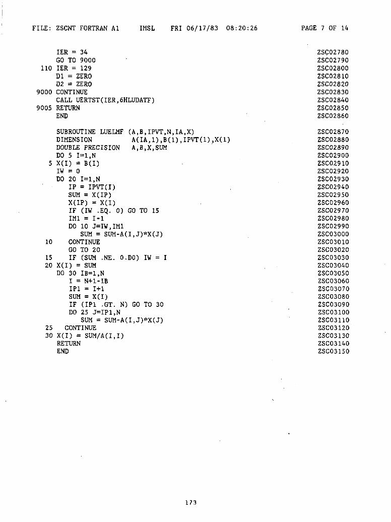
FILE: ZSCNT FORTRAN Al IMSL FRI 06/17/83 08:20:26 PAGE 7 OF 14
IER = 34GO TO 9000
110 IER = 129Dl = ZEROD2 = ZERO
9000 CONTINUECALL UERTST(IER,6HLUDATF)
9005 RETURNEND
SUBROUTINE LUELMF (A,B,IPVT,N,IA,X)DIMENSION A(IA,i:DOUBLE PRECISION A,B,X,SUMDO 5 1=1,N
5 X(I) = B(I)IW = 0DO 20 1=1,N
IP = IPVT(I)SUM = X(IP)X(IP) = X(I)IF (IW .EQ. 0) GO TO 15IM1 = 1-1DO 10 J=IW,IM1
SUM = SUM-A(I,J)*X(J)10 CONTINUE
GO TO 2015 IF (SUM .NE. O.DO) IW = I20 X(I) = SUM
DO 30 IB=1,NI = N+l-IBIP1 = 1+1SUM = X(I)IF (IP1 .GT. N) GO TO 30DO 25 J=IP1,N
SUM = SUM-A(I,J)*X(J)25 CONTINUE30 X(I) = SUM/A(I,I)
RETURNEND
ZSC02780ZSC02790ZSC02800ZSC02810ZSC02820ZSC02830ZSC02840ZSC02850ZSC02860
ZSC02870ZSC02880ZSC02890ZSC02900ZSC02910ZSC02920ZSC02930ZSC02940ZSC02950ZSC02960ZSC02970ZSC02980ZSC02990ZSC03000ZSC03010ZSC03020ZSC03030ZSC03040ZSC03050ZSC03060ZSC03070ZSC03080ZSC03090ZSC03100ZSC03110ZSC03120ZSC03130ZSC03140ZSC03150
173

FILE: ZSCNT FORTRAN Al IMSL FRI 06/17/83 08:20:26 PAGE 8 OF 14
SUBROUTINE LUREFF (A,B,UL,IPVT,N,IA,X,IDGT,RES,DX,IER)DIMENSION A(IA,l)fUL(IA,l),B(l),X(l),RES(l),DX(l),DIMENSION ACCXT(2)DOUBLE PRECISION A,ACCXT,B,UL,X,RES,DX,ZERO,XNORM,DXNORMDATA ITMAX/75/,ZERO/0.DO/IER=0XNORM = ZERODO 10 1=1, N.
XNORM = DMAX1(XNORM,DABS(X(I)))10 CONTINUE
IF (XNORM .ME. ZERO) GO TO 20IDGT = SOGO TO 9005
20 DO 45 ITER=1,ITMAX-DO 30 1=1,N
ACCXT(l) = O.ODOACCXT(2) = O.ODO
CALL VXADD(B(I),ACCXT)DO 25 J=1,N
CALL VXMUL(-A(I,J),X(J),ACCXT)25 CONTINUE
CALL VXSTO(ACCXT,RES(I))30 CONTINUE
CALL LUELMF (UL,RES,IPVT,N,IA,DX)DXNORM = ZEROXNORM = ZERODO 35 1=1,N
X(I) = X(I) + DX(I)DXNORM = DMAX1(DXNORM,DABS(DX(I)))XNORM = DMAX1(XNORM,DABS(X(I)))
35 CONTINUEIF (ITER .NE. 1) GO TO 40IDGT = 50IF (DXNORM .NE. ZERO) IDGT = -DLOG10(DXNORM/XNORM)
40 IF (XNORM+DXNORM .EQ. XNORM) GO TO 900545 CONTINUE
IER = 1299000 CONTINUE
CALL UERTST(IER,6HLUREFF)9005 RETURN
END
i SUBROUTINE UERSET (LEVEL,LEVOLD)INTEGER LEVEL,LEVOLDLEVOLD = LEVELCALL UERTST (LEVOLD,6HUERSET)RETURNEND
ZSC03160IPVT(1)ZSC03170
ZSC03180ZSC03190ZSC03200ZSC03210ZSC03220ZSC03230ZSC03240ZSC03250ZSC03260ZSC03270ZSC03280ZSC03290ZSC03300ZSC03310ZSC03320ZSC03330ZSC03340ZSC03350ZSC03360ZSC03370ZSC03380ZSC03390ZSC03400ZSC03410ZSC03420ZSC03430ZSC03440ZSC03450ZSC03460ZSC03470ZSC03480ZSC03490ZSC03500ZSC03510ZSC03520ZSC03530ZSC03540ZSC03550ZSC03560
ZSC03570ZSC03580ZSC03590ZSC03600ZSC03610ZSC03620
174
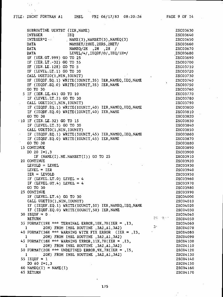
FILE: ZSCNT FORTRAN Al IMSL FRI 06/17/83 08:20:26 PAGE 9 OF 14
SUBROUTINE UERTST (IER,NAME)INTEGER IEQINTEGER*2 • • , NAME(3),NAMSET(3),NAMEQ(3)DATA NAMSET/2HUE,2HRS,2HET/DATA NAMEQ/2H ,2H ,2H /DATA LEVEL/4/ , IEQDF/.0/ , IEQ/ 1H=/IF (IER.GT.999) GO TO 25IF (IER.LT..-32) GO TO 55IF (IER.LE.128) GO TO 5IF (LEVEL.LT.l) GO TO 30CALL UGETIO(1,NIN,IOUNIT)IF (IEQDF.EQ.1) WRITE(IOUNIT,35) IER,NAMEQ,IEQ,NAMEIF (IEQDF.EQ.O) WRITE(IOUNIT,35) IER,NAMEGO TO 30
5 IF (IER.LE,.64) GO TO 10IF (LEVEL.LT.2.) GO TO 30CALL UGETIO(1,NIN,IOUNIT)IF (IEQDF.EQ.1) WRITE(IOUNIT,40) IER,NAMEQ,IEQ,NAMEIF (IEQDF.EQ.O) WRITE(IOUNIT,40) IER.NAMEGO TO 30
10 IF (IER.LE.32) GO TO 15IF (LEVEL.LT.3) GO TO 30CALL UGETIO(1,NIN,IOUNIT)IF (IEQDF.EQ.1) WRITE(IOUNIT,45) IER,NAMEQ,IEQ,NAMEIF (IEQDF.EQ.O) WRITE(IOUNIT,45) IER,NAMEGO TO 30
15 CONTINUEDO 20 1=1,3
IF (NAME(I).NE.NAMSET(I)) GO TO 2520 CONTINUE
LEVOLD = LEVELLEVEL'= IERIER = LEVOLDIF (LEVEL.LT.O) LEVEL = 4IF (LEVEL.GT.4) LEVEL = 4GO TO 30
25 CONTINUEIF (LEVEL.LT.4) GO TO 30CALL UGETIO(1,NIN,IOUNIT)IF (IEQDF.EQ.1) WRITE(IOUNIT,50) IER,NAMEQ,IEQ,NAMEIF (IEQDF.EQ.O) WRITE(IOUNIT,50) IER,NAME
30 IEQDF = 0RETURN
35 FORMAT(19H *** TERMINAL ERROR,10X,7H(IER = ,13,1 20H) FROM IMSL ROUTINE ,3A2,A1,3A2)
40 FORMAT(36H *** WARNING WITH FIX ERROR (IER = ,13,1 20H) FROM IMSL ROUTINE ,3A2,A1,3A2)
45 FORMAT(18H *** WARNING ERROR,1IX,7H(IER = ,13,1 20H) FROM IMSL ROUTINE ,3A2,A1,3A2)
50 FORMAT(20H *** UNDEFINED ERROR,9X,7H(IER = ,15,1 - 20H) FROM IMSL ROUTINE ,3A2,A1,3A2)
55 IEQDF = 1DO 60 1=1,3
60 NAMEQ(I) = NAME(I)65 RETURN
ZSC03630ZSC03640ZSC03650ZSC03660ZSC03670.ZSC03680ZSC03690ZSC03700ZSC03710ZSC03720ZSC03730ZSC03740ZSC03750ZSC03760ZSC03770ZSC03780ZSC03790ZSC03800ZSC03810ZSC03820ZSC03830ZSC03840ZSC03850ZSC03860ZSC03870ZSC03880ZSC03890ZSC03900ZSC03910ZSC03920ZSC03930ZSC03940ZSC03950ZSC03960ZSC03970ZSC03980ZSC03990ZSC04000ZSC04010ZSC04020ZSC04030ZSC04040ZSC04050ZSC04060ZSC04070ZSC04080ZSC04090ZSC04100ZSC04110ZSC04120ZSC04130ZSC04140ZSC04150ZSC04160ZSC04170
175

FILE: ZSCNT FORTRAN Al IMSL FRI 06/17/83 08:20:26 PAGE 10 OF 14
END
SUBROUTINE UGETIO(IOPT,NIN,NOUT)INTEGER IOPT,NIN,NOUTINTEGER NIND,NOUTDDATA . NIND/5/.NOUTD/6/IF (IOPT.EQ.3) GO TO 10IF (IOPT.EQ..2) GO TO 5IF (IOPT.NE.1) GO TO 9005NIN = NINDNOUT = NOUTDGO TO 9005
5 NIND = NINGO TO 9005
10 NOUTD = NOUT9005 RETURN
END
SUBROUTINE VXADD(A.ACC)DOUBLE PRECISION A,ACC(2)DOUBLE PRECISION X.Y.Z.ZZX = ACC(l)Y = AIF (DABS(ACC(1)).GE.DABS(A)) GO TO 1X = AY = ACC(l)
1 Z = X+YZZ = (X-Z)+YZZ = ZZ+ACC(2)ACC(l) = Z+ZZACC(2) = (Z-ACC(1))+ZZRETURNEND
ZSC04180
ZSC04190ZSC04200ZSC04210ZSC04220ZSC04230ZSC04240ZSC04250ZSC04260ZSC04270ZSC04280ZSC04290ZSC04300ZSC04310ZSC04320ZSC04330
ZSC04340ZSC04350ZSC04360ZSC04370ZSC04380ZSC04390ZSC04400ZSC04410ZSC04420ZSC04430ZSC04440ZSC04450ZSC04460ZSC04470ZSC04480
176
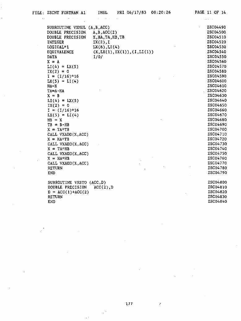
FILE: ZSCNT FORTRAN Al IMSL FRI 06/17/83 08:20:26 PAGE 11 OF 14
LX(8),LI(4)
I/O/
SUBROUTINE VXMUL (A.B.ACC)DOUBLE PRECISION A,B,ACC(2)DOUBLE PRECISION X,HA,TA,HB,TBINTEGERLOGICAL*!EQUIVALENCEDATAX = ALI(4) = LX(5)IX(2) = 0I = (I/16)*16LX(5) = LI(4)HA=XTA=A-HAX = BLI(4) = LX(5)IX(2) = 0I = (I/16)*16LX(5) = LI(4)HB = XTB = B-HBX = TA*TBCALL VXADD(X,ACC)X = HA'-TBCALL VXADD(X.ACC)X = TA-HBCALL VXADD(X.ACC)X = HA*HBCALL VXADD(X.ACC)RETURNEND
SUBROUTINE VXSTO (ACC.D)DOUBLE PRECISION ACC(2),DD = ACC(1)+ACC(2)RETURNEND
ZSC04490ZSC04500ZSC04510ZSC04520ZSC04530ZSC04540ZSC04550ZSC04560ZSC04570ZSC04580ZSC04590ZSC04600ZSC04610ZSC04620ZSC04630ZSC04640ZSC04650ZSC04660ZSC04670ZSC04680ZSC04690ZSC04700ZSC04710ZSC04720ZSC04730ZSC04740ZSC04750ZSC04760ZSC04770ZSC04780ZSC04790
ZSC04800ZSC04810ZSC04820ZSC04830ZSC04840
177
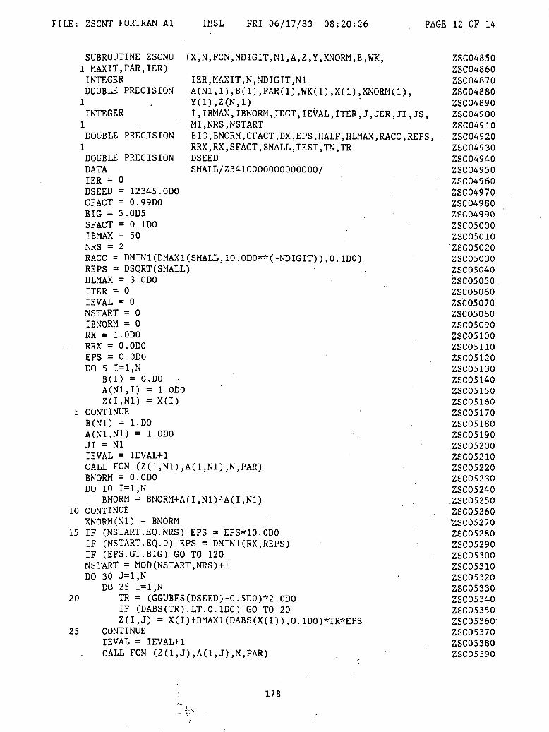
FILE: ZSCNT FORTRAN Al IMSL FRI 06/17/83 08:20:26 PAGE 12 OF 14
SUBROUTINE ZSCNU (X,N,FCN,NDIGIT,N1,A,Z,Y,XNORM,B,WK,1 MAXIT,PAR,IER)INTEGER IER,MAXIT,N,NDIGIT,N1DOUBLE PRECISION A(N1, 1) ,B(1) ,PAR(1) ,WK(1) ,X(1) ,XNORM(1) ,
INTEGER
DOUBLE PRECISION
I,IBMAX,IBNORM,IDGT,IEVAL,ITER,J,JER,JI,JS,MI, NRS, NSTARTBIG, BNORM, CFACT.DX, EPS, HALF, HLMAX,RACC, REPS,RRX,RX,SFACT, SMALL, TEST, TN.TRDSEEDSMALL/Z3410000000000000/
DOUBLE PRECISIONDATAIER = 0DSEED = 12345.ODOCFACT = 0.99DOBIG = 5.0D5SFACT = 0.1DOIBMAX = 50NRS = 2RACC - DMIN1(DMAX1(SMALL,10.0DO**(-NDIGIT)),0.1DO)REPS = DSQRT(SMALL)HLMAX = 3.ODOITER = 0IEVAL = 0NSTART = 0IBNORM = 0RX = l.ODORRX = O.ODOEPS = O.ODODO 5 1=1,N
B(I) = O.DOA(N1,I) = l.ODOZ(I.Nl) = X(I)
5 CONTINUEB(N1) = 1-DOA(N1,N1) = l.ODOJI = NlIEVAL = IEVAL+1CALL FCN (Z(1,N1),A(1,N1),N,PAR)BNORM = O.ODODO 10 1=1,N
BNORM = BNORM+A(I,N1)*A(I,N1)10 CONTINUE
XNORM(Nl) = BNORM15 IF (NSTART.EQ.NRS) EPS = EPS*10.ODO
IF (NSTART.EQ.O) EPS = DMINl(RX.REPS)IF (EPS.GT.BIG) GO TO 120NSTART = MOD(NSTART,NRS)+lDO 30 J=1,N
DO 25 1=1,N20 TR = (GGUBFS(DSEED)-0.5DO)*2.ODO
IF (DABS(TR).LT.O.IDO) GO TO 20Z(I,J) = X(I)+DMAX1(DABS(X(I)),0.1DO)*TR*EPS
25 CONTINUEIEVAL = IEVAL+1CALL FCN (Z(1,J),A(1,J),N,PAR)
ZSC04850ZSC04860ZSC04870ZSC04880ZSC04890ZSC04900ZSC04910ZSC04920ZSC04930ZSC04940ZSC04950ZSC04960ZSC04970ZSC04980ZSC04990ZSC05000ZSC05010ZSC05020ZSC05030ZSC05040ZSC05050ZSC05060ZSC05070ZSC05080ZSC05090ZSC05100ZSC05110ZSC05120ZSC05130ZSC05140ZSC05150ZSC05160ZSC05170ZSC05180ZSC05190ZSC05200ZSC05210ZSC05220ZSC05230ZSC05240.ZSC05250ZSC05260'ZSC05270ZSC05280ZSC05290ZSC05300ZSC05310ZSC05320ZSC05330ZSC05340ZSC05350ZSC05360-ZSC05370ZSC05380ZSC05390
178
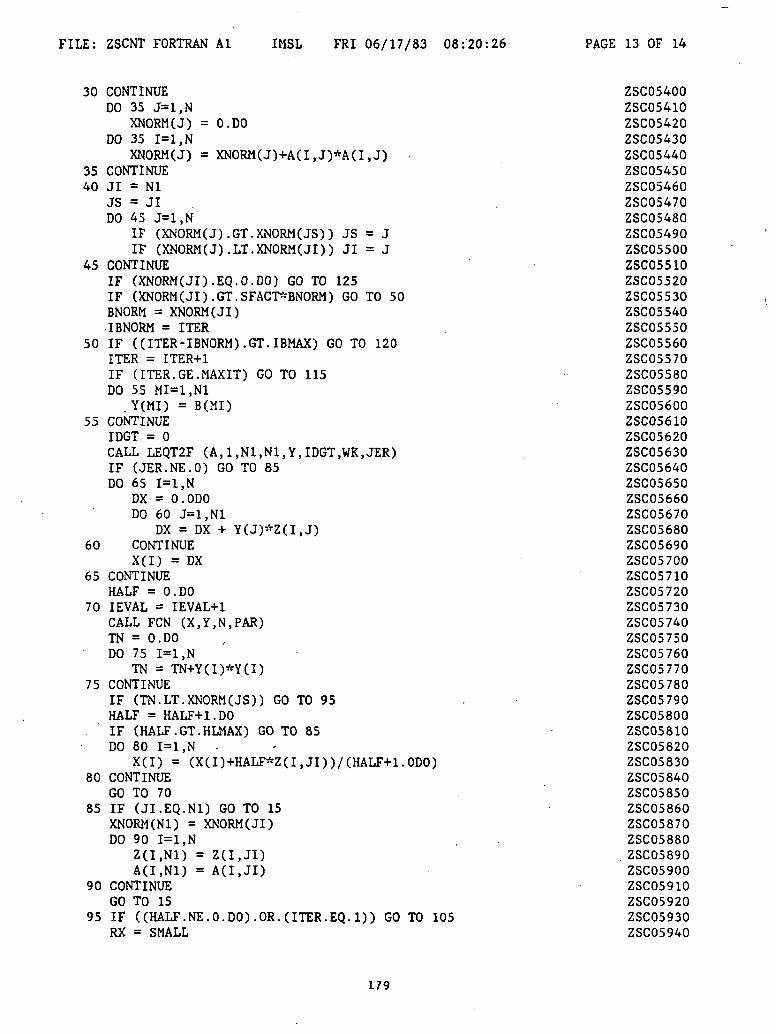
FILE: ZSCNT FORTRAN Al IMSL FRI 06/17/83 08:20:26 PAGE 13 OF 14
30 CONTINUEDO 35 J=1,N
XNORM(J) = O.DODO 35 1=1, N
XNORM(J) = XNORM(J)+A(I,J)*A(I,J)35 CONTINUE40 JI = Nl
JS = JIDO 45 J=1,N
IF (XNORM(J).GT.XNORM(JS)) JS = JIF (XNORM(J).LT.XNORM(JI)) JI = J
45 CONTINUEIF (XNORM(JI).EQ.O.DO) GO TO 125IF (XNORM(JI).GT.SFACT*BNORM) GO TO 50BNORM = XNORM(JI)IBNORM = ITER
50 IF ((ITER-IBNORM).GT.IBMAX) GO TO 120ITER = ITER+1IF (ITER.GE.MAXIT) GO TO 115DO 55 MI=1,N1
. Y(MI) = B(MI)55 CONTINUE
IDGT = 0CALL LEQT2F (A, 1,N1,N1,Y,IDGT,WK, JER)IF (JER.NE.O) GO TO 85DO 65 1=1, N
DX = O.ODODO 60 J=1,N1
DX = DX + Y(J)*Z(I,J)60 CONTINUE
X(I) = DX65 CONTINUE
HALF = O.DO70 IEVAL = IEVAL+1
CALL FCN (X,Y,N,PAR)TN = O.DODO 75 1=1, N
TN = TN+Y(I)*Y(I)75 CONTINUE
IF (TN.LT.XNORM(JS)) GO TO 95HALF = HALF+l.DOIF (HALF.GT.HLMAX) GO TO 85DO 80 1=1 ,N •
X(I) = (X(I)+HALF*Z(I,JI))/(HALF+1.0DO)80 CONTINUE
GO TO 7085 IF (JI.EQ.N1) GO TO 15
XNORM(Nl) = XNORM(JI)DO 90 1=1, N
90 CONTINUEGO TO 15
95 IF ((HALF. NE. O.DO). OR. (ITER. EQ.l)) GO TO 105RX = SMALL
ZSC05400ZSC05410ZSC05420ZSC05430ZSC05440ZSC05450ZSC05460ZSC05470ZSC05480ZSC05490ZSC05500ZSC05510ZSC05520ZSC05530ZSC05540ZSC05550ZSC05560ZSC05570ZSC05580ZSC05590ZSC05600ZSC05610ZSC05620ZSC05630ZSC05640ZSC05650ZSC05660ZSC05670ZSC05680ZSC05690ZSC05700ZSC05710ZSC05720ZSC05730ZSC05740ZSC05750ZSC05760ZSC05770ZSC05780ZSC05790ZSC05800ZSC05810ZSC05820ZSC05830ZSC05840ZSC05850ZSC05860ZSC05870ZSC05880ZSC05890ZSC05900ZSC05910ZSC05920ZSC05930ZSC05940
179
FILE: ZSCNT FORTRAN Al IMSL FRI 06/17/83 08:20:26 PAGE 14 OF 14
DO 100 1=1,N ZSC05950RX = DMAX1(RX,DABS(X(I)-Z(I,JI))/DMAX1(DABS(X(I)),0.1DO)) ZSC05960
100 CONTINUE ZSC05970RRX = DMAX1(-DLOG10(RX),O.ODO) ZSC05980IF (RX.LE.RACC) GO TO 125 ZSC05990
105 IF (TN.LT.CFACT*XNORM(JI)) NSTART = 0 ZSC06000XNORM(JS) = TN . ZSC06010DO 110 1=1,N ZSC06020
Z(I,JS) = X(I) ZSC06030A(I,JS) = Y(I) ZSC06040
110 CONTINUE ZSC06050GO TO 40 ZSC06060
115 IER = 129 ZSC06070GO TO 125 ZSC06080
120 IER = 130 i ZSC06090125 DO 130 I=1,N ZSC06100
X(I) = Z(I,JI) ZSC06110130 CONTINUE , ZSC06120
RETURN ZSC06130END ZSC06140
180

LOO
90
80
700)Cfl
oo.
§ 60
APPENDIX C
RESULTS OF EXPERIMENTS - NEW SERIES
ooen 50
40
30
20 I I
35
I
40
I I
45 50 55 60Temperature (°C)
I I I I I I I
65
I
70
I95 100 105 110 115 120 125 130 135
Temperature (°F)
140 145 150 155 160
Fig. C-l Viscosity of 20W40 Oil
181

-2t
IfJ
«*!
^leof*
Or
r o00 J)±
12
00
*2
t<i tfl cfi •*<
08 tJ
S2
^•55
••««
QC «^
l^
*-
.••
J£
sri*
dtfS ***«?
as<tir
UJ V)lfl<
*5
S3OQ
^
ifl-» tfl*
Nfv
i
S4
^f4
<P
^f
IM
NN
O
HO
<£
«.£
(£(£
«o
3s:
00
H<T
«^ r
it
s !
NOTES:DATE:
i
j
182
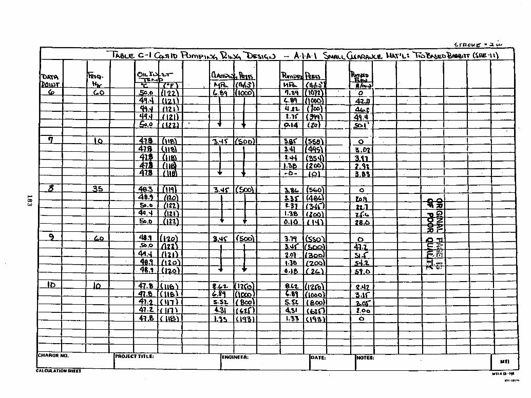
••ji10
IIuJfc
$
.^fii^
S:?
^
cs, e-J
.
{?
^§
009*. CO «s» (O
Iin
(R(IFA
G1NAL
POO
R8
dU
AO
Tt
</] ,
VI i/ v
,^
i*«
OD
^
MO fJ r*
183
5 !i S
1H-O
EER
jc
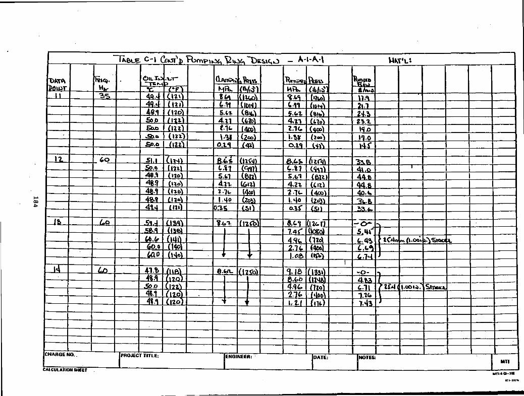
sIc£
Ijrf
i.^
a ^^^5
UN
^f
PJ
£ <
B
q2
«r
0?
,si^f^^
V>
'I
Vj «C
*]7m
T
Nj
»ol J
.c
O-flO
^J-
5 !a
B
EUJ
184
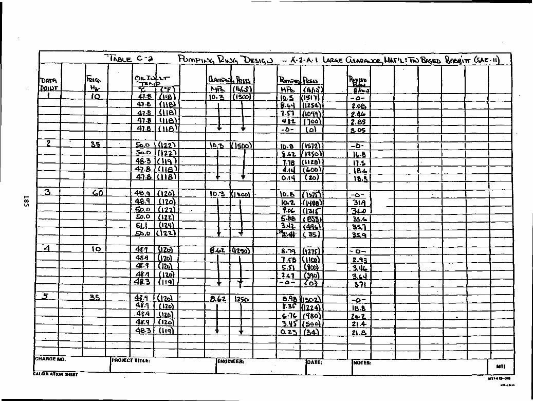
k1C0
ItM\&f*iOI£
j^ J
O
24.
355=
j- 0]oO
aC «Q
M«
»-W
)<*>
^
^^^a
IHN
jrgq
33
ll
$i
185

(uhi
0*/
1§1-
J'U
S°
2 ooS
<S
C5
**I
%#$%$ T.
CO
c.
;
5!
I
<C£T§!
186

J!2OJ
F
•Vj
h
1f.s-G#
S*
ON
,.
Ort
q- «A3 r*
tsl
yor-
cr00
s !a
B
2iIUQ
UlIIu
187

&J*
mof
5r*1
«TN
I/3
HI
M
=+I
If
«5T?-<S
e
U.03
2'F
£Z
N^^
d
(O
^^
^4
™ ^
V
•
SifitJi^^O
5vS^a*
(OtJ
**f
3utg
188

If 21tf«
.<* O
o 5 V:M
J8
^!^Q
v£S
aa
0
28
§r^
£ro
!Lfl
^
i
li. C^
t* I** H
i £*£!
r* r* M•*V
*tM
P
<3
t»*
rJ
Ul V
fl«OU
>n
HU
>U)
in
tl:ispgii5
189O
RIG5N
AL
PAG
E; 9SO
F POO
R
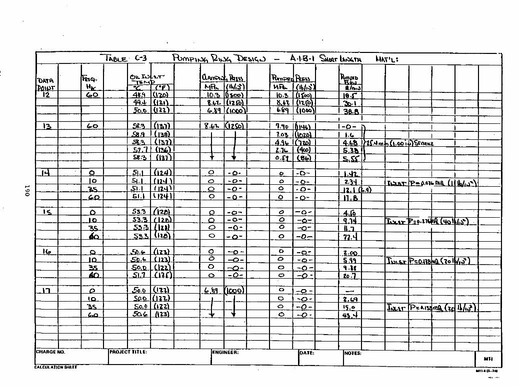
J2fJfl
J•101* 2£fsjM
M*
1
J JB
PCJ(f-
jS^TI.^f.
H&P
«'ai%£rf5u.t
*ij
<pJ^—inc8i»«0
—Q>^«0£f
-|"yd3£}
J>00
£"•1
«CSS0^^$r~B1o)0
^*»— i
0•fi
io\*tsor31N,*
DCg"*cf9i0sSi!
-jSv—O£1"k j'iSB
*
£«fr-*>—<r
2jf
40
«*»
101^2si fci/ioao™s3
•?10105**
100T
52<fP-P«/M•rN10Qii
77^^
tf0
'pc-I00N*io*
aO^^iQ10ii
5u>C
•i
\0t1<f1§*•
(Tl*i0t
^—15H1&,I-*;r•»rr100i
1*•O0
ri0ot"*!rJ
flf
-rPtQ1
0in1
1i/i4
8i0010fru*•t
Q*
^*-.<c.IfrhV4
/^»-
I/I
01
010ra"o0
rr10f01Q1£C]fff
F^
c^(f0t1<-•~f<
110'
0o_?of
OQr
5(Stt00r*
*•«OciU
l
0
^^«Cej(iurff0100N*-
oOMft
TTi90tk
11vl
X
tnuiu3oeIUnzSiPROJEC
§
ICHARGE
CAICU1ATI
190
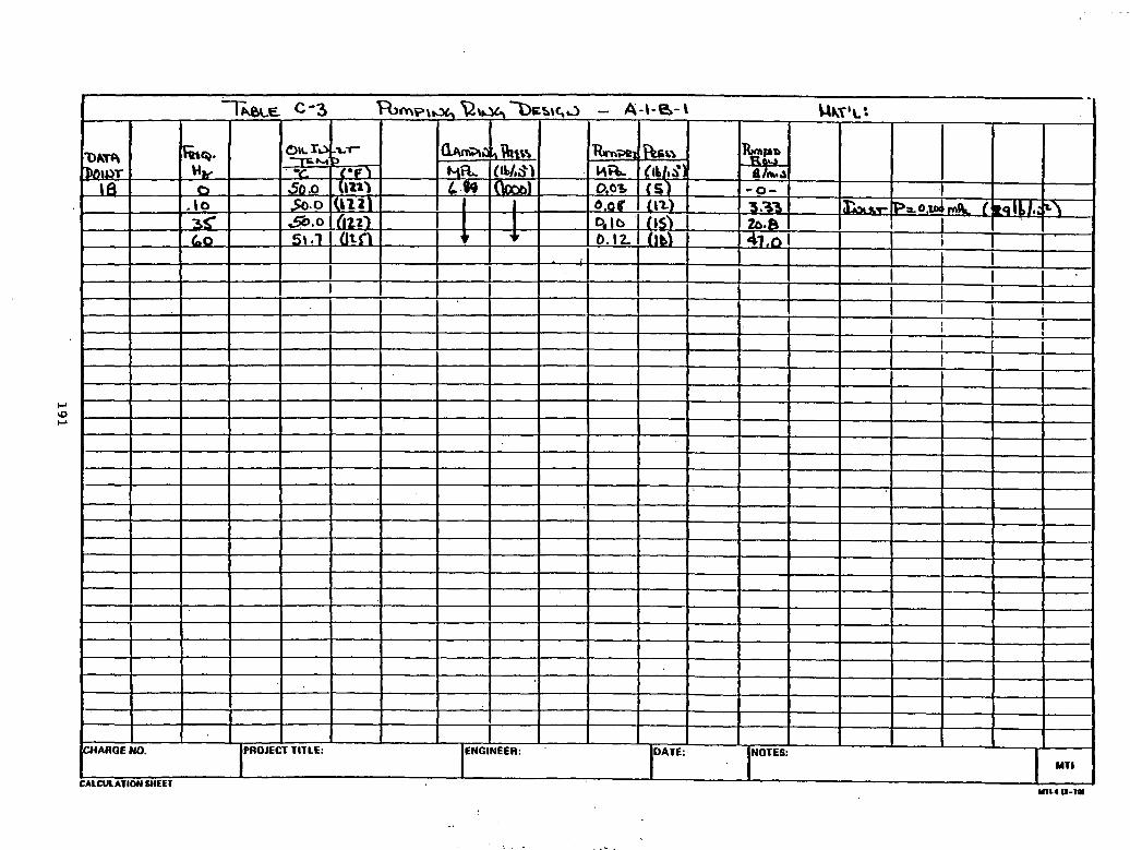
••JL»5tiIi
<10•j-#/5if3&i1(?rO\<J$r.1
°f&(X5acCjj
j?3
^b•Jf
-!o»0$
IP
•i
4«»^3Srf
A*r>"£(t*5IL•
•>Ji|
10uJ*•*
|A0cSis>J4oo«o000
^"flc"j^^~^1s_i1cA.1;*ff *
I?(04*"'
baOC«^
^n
MH•O^O
-«^£o0'•
M
««*NN—o4VifO
Q4?
*2cJo>v«fj
—)(no^3
,
?NOTES:u(juZI5juujiiICHARQE
ni « u-iai
191

-J
5
24rn
tfl
fiM
SJs-
8?*oo eo
to
•^ M
oy.|
uOr O
o
vSuS
r*
<2I
* S2 —C
E
N iC
«en
^^^
JU
&
^ol5
5"
192
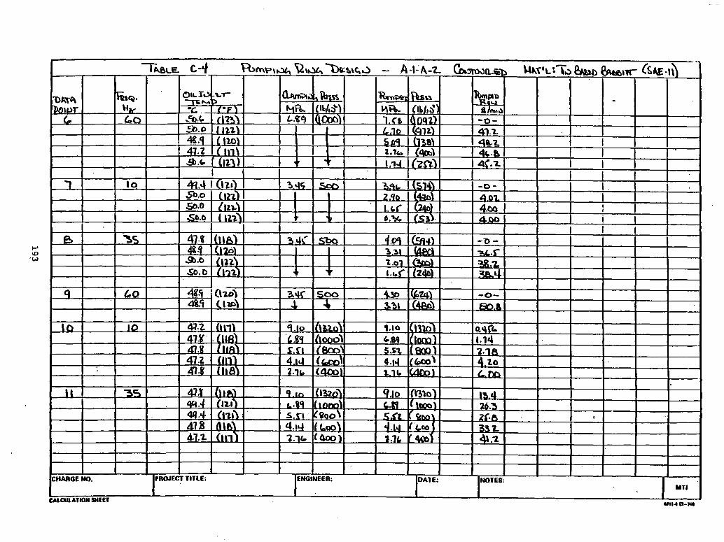
JsoO3
24
<Dii.ro1 '
ss
i^
iJd |J
i^V
l
U•
58
q*|<5J
I5ur«T
^^
*"*sS 2
itr-T
Cl
Sn
<
!^
193

J5a-0
IMN
10o-id
P
v -3 (O3
C*
u>-tf
3
(frI
o' F*4
f*-9»
9
i!PAj
194

•»-J
1
12;«!«r*
«r<r Vdf> u»
<<>UT
fi/>
,j(<i r*>
an
do
-en
1/13*1
<
(O
^
C*£
to31
3^3
irO ao
"3^F*
^
W^
» »•
^F
^^^
^^^^
a
&f* *o
fOi
195
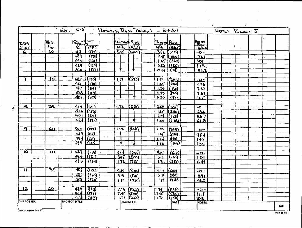
tei~
10
>9
i/N
S3
P
v?/o r*
tf,vfM
,
•a^jdro'
5O
8
t<JuJ
«»• H
iJ?
^^
I^S
*3
^5
II
9I
196

U)
£J
8 *Nu» in
|J«9
K as<0$
4$
z**«
*£
*
•si
53
ia
<aUlIIj
197

l.i1
^«fl ff>s
d,9
SI J
do-00:
'"aOV.2
P
S\2
f"n
M
ui
I<r
<r$
^3
3:3
o:
^^1
*.%%
ic*/
198
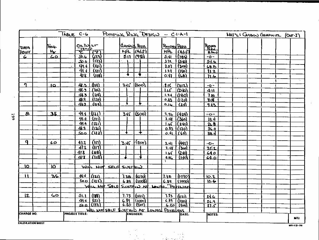
0Itf••J5
J
P-W
T.rfi
& 1
01
<rV
'§
if,
CO-
gc
j/•
11i«/2
z
vi«s
V
•iS^«x
IPIT
cJ>is
199

<£0S
242
2M
M
2i
Ia
s1H
S2
d«6
2Pi
>
r«
<r i
•*efl -3
enm
uit
i°
J5200
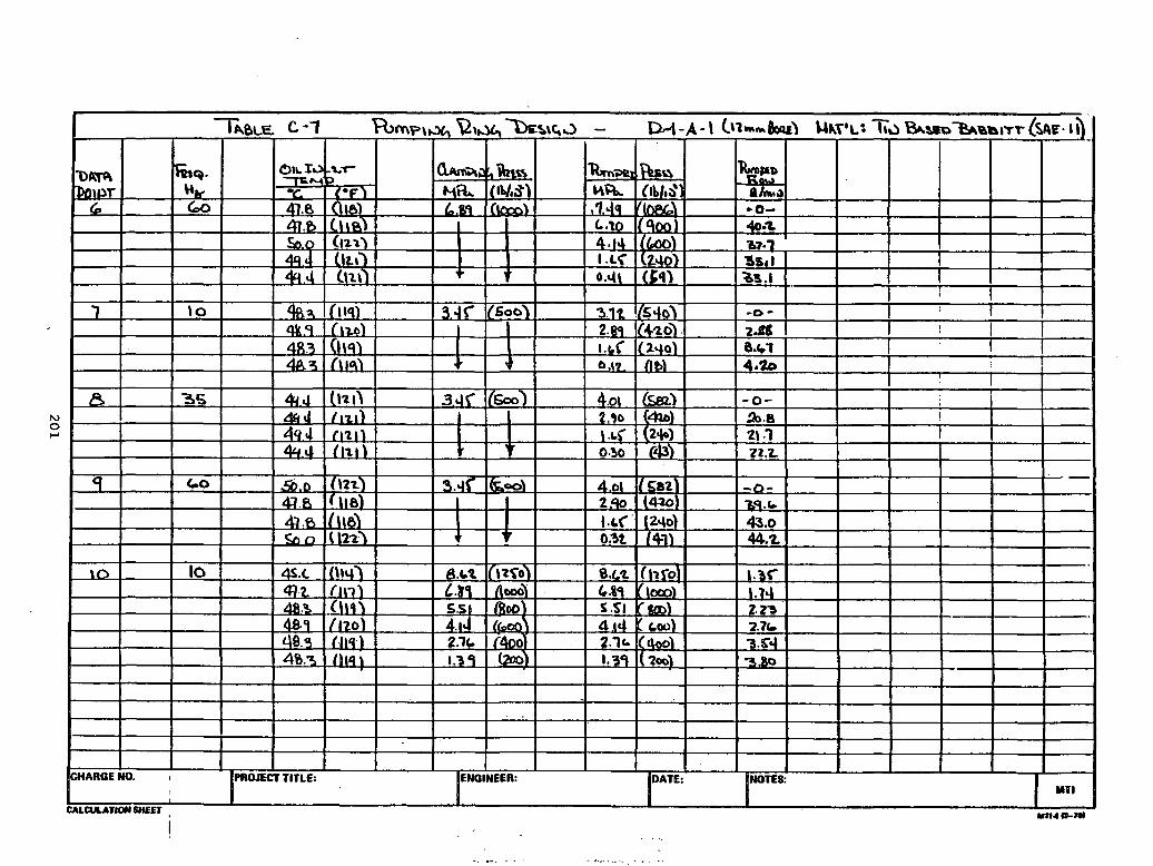
bi
&
.mtf«
21F
S
u.^
**
tf <C
50-9
-J
«?r* «
«MCM
IIP «PrN
<M
^^i
a*
oS
rf «^
1U4eO
£v
? a^s
.s .
.oO
xi in -^ M
3
«,-.
•o-K
201
a
SS
i
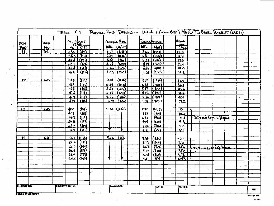
1iCO
JiII
w'•3
^
f*fi
N
iy o vi TJ
§
JrJIi
$
35
(P
oi
-,«0
4<rS
o> O
00
Oa
LA
MH
N
2*11
Wl
VJ
?
o
5Q
i
20
2

APPENDIX D
FIGURES SHOWING COMPARISON WITH EXPERIMENTAL DATA
AND UNCORRECTED THEORY
QCd
-•HH
)
N—
/
I
*
frJ ^1X-Sr"
•H
hJ
">
^0
O
rH
rHCd
•cd -H
Of
CO
S
P-
X—
\
4-1
•
CO
C
0 -H
° 1x
-sg
. ^13MOS
.WH3ori
CM m
en
i-H
• rHC
M
•
X-N
oo P
-PS,
vo• (M
vO
.oao
m C
M
P-
0vOCO
oX-N
r~ m•
•rH
p-
m s—
'
x-s
en r*
•-j 3rH
•
X-S
co m•st <•rH
0X"s
inCM
r-in
coen o
4J
3&J3cdmM
CN m
en rH. rH
CM
•
X"N
oo r»
p*
vO
• C**4
vO
.OX-N
oovO
O
>m
CM
^ S
vOCO
o
x-s
r>. m•
•rH
r-
m v
-'
13
rH
•
X""N
m m
o
s-en
omCM
r~m
coen
o
•u«J3
43Cd
nMM
CM m
en rH•
i-HC
M
oo r>.
r- vo
• CM
vo •
ooovo enm
CM
r-. O
vO^3-
OCM
x-\t-~
m• C
M1-1
•s^
vr Co
<<T en
. oC
M
•
inin
r~in
vo
CM
i-Hm
CM r~
m co
CJN O
^coi-HǤ>
CM m
en I-H. rH
es •
v-x
x-s
00
P
£
• CM
vO
•000
vo enm
CM
r~ o
enCM
O
rHin
rH
•
•
rH C
OC
M ^x-s
vr vo
".SrH
•
in o
CO
00
o ox
-\in
CM r*
m c
o
en o
gjaMcdorH
CO
vO
en p^. o
rH
•
8c7•
•m
o
en CMm
CM
m o
vOCO
0r~ m
• •
rH
P^
in v
-'
x-s
tn m
OO
C
O•
oo .
en in
00
CO
00
Ovo"O
co
O C
M
vO
O
4Ju•H.0ftcd«t-trH
O4JcCO3oOCMCOCOcdecd<Un34Jcdrl
0)
8 10)
4JCOIDO.
4-1
60
•HT3coo.COt-iOCJcd4J
•a0)CO3COooCO0)
H•K
20
3

9CM
00coc•rlC.
ee-<aocCO
uo<uCUoc
CN
—
1
O
20
4
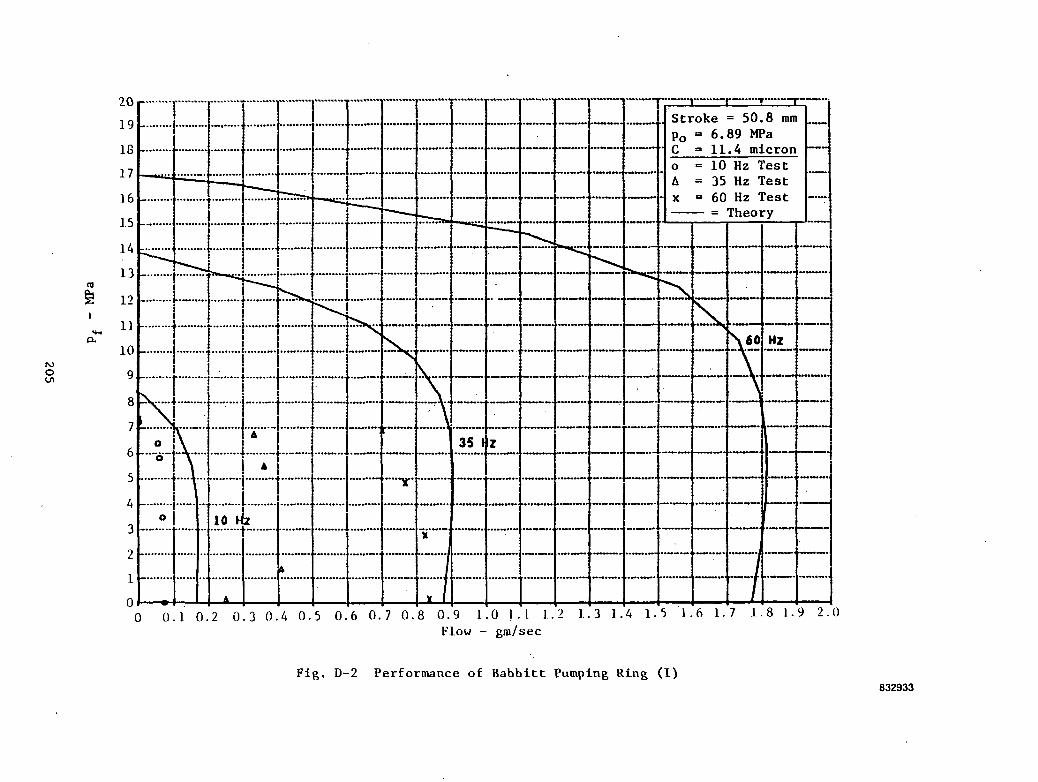
§00cooe3CU_0
.O«OJOOJaCEOa-CMQ
20
5

00c60
o
•sPQCUUo14-1
0100•rlC
b
206
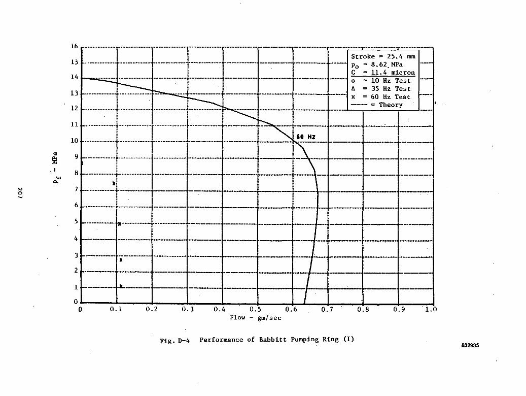
oc00cT-l
I(X,
* oa<uCJCoiwU<Uo•
oflt-iP
u
20
7
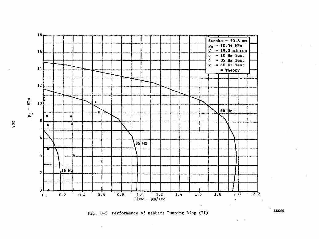
eccODC•HO.
3&<JO&n03(Uu<Dcuoc
20
8

o41en•00o
00
•HPS00(3
P-.
4-1
•80)ooM-l
vO00
209
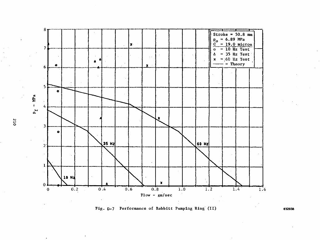
u<uCO
"aacor-((**
6DC00
1-1acapa0)ucCOoc•H
- Jd
210

s ou
•? ct- o
•XS
104
<^
On
vo •
• ON
JU 00
rH
O
II II
M4J O
CO
O.C
J
GO CQ
co41
CD
01 >>
H H
H
C
*o
N
N
N «
• «
*£
O^
OO
»H
<*"! vO
II
II II
II
o <
:*»
CO
CO
o
y<u"»'
01oni0
eo00caeucoU-loCJCW
i<uPu
ao6C•H
211
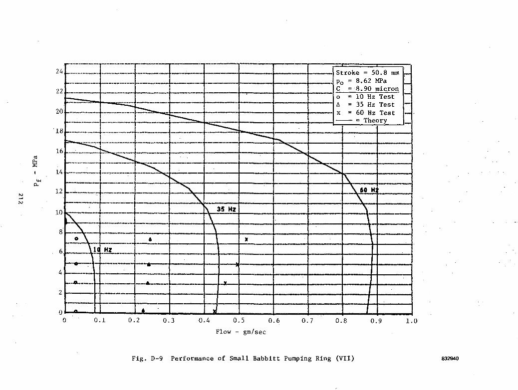
8
o<uwO
00
•H60
•Ha.3a.01oc0)pt.OO
C•H
212

ecc•HOSacC•H•so>oo(4-1
oi-HI60•H
O '
213

u01COooo
00cc•Ho.ePL,
J3J3<0pa0)oc01PHO
C•H
214

3CMCOCO
en<UH
H
H
MoN
N
N
01
BC SS
SC
4=
60C60
•Ha.3CQ0)aMoM-l
M0)PL,
csi-HI60
B.IH
-
215

Given C and p
. Q
Fig. D-13 Qualitative Comparisons of Theoretical and Experimental Results
831236
216
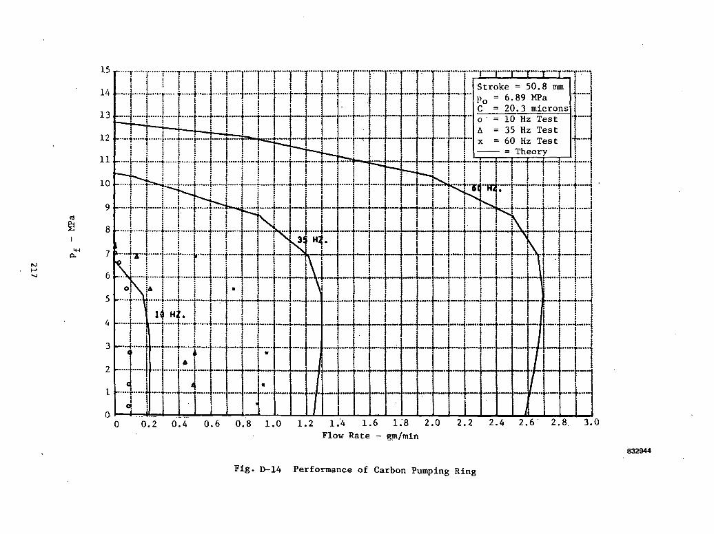
CM
eoco
60C60CPi
Cocdu<uuCcdMoU-lM0)
PL,
OC
217
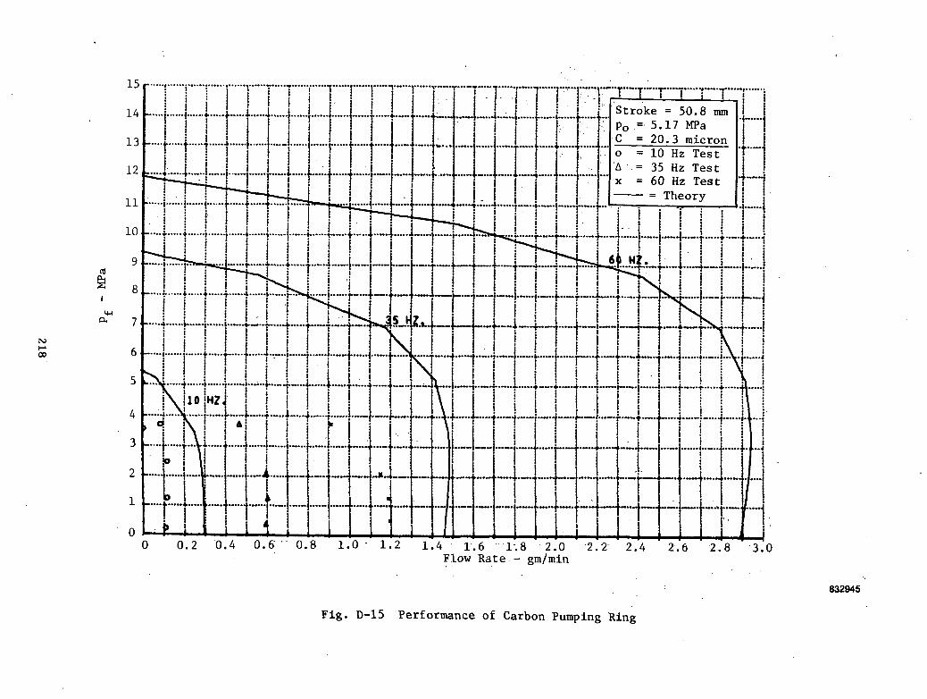
CMnCO
00
.5IPHco•sn)oCo0)
mQoo•H
218

L
i!!§ c
6
oh00
CO
O*
PM
"^O
§ B
min
roII
-a- •
• o
<u r> CM0
II II
M4J O
W
O.O
:!s
iiiiIi
4-1 4J
4-1CO
GO CO
01 0>
0) >,
H H
H
UON
N
N
0)
3J
5C
3
d£
o m
oiH
en
vO
II
II II
II
o <
X:!j:i
i i}ii|•i•s•i||jji*1!ii1
ii]il1it
60C00
•HO.
0)D.
n)MCo(0O01OCM01
vO60•H
219

CM
s
«gooomu0)oM4J
V)
tI.0O
4J
V
CO
cd a
oiPH
T
t H
2 eN
r^ m
SC
rH
•.{
MO
in
>* r-H
II II
II
OG
. U
O
4-1
4-1
CO
CO<U
V
>>
H H
MON
N
01jjj
PC
,J^H
m o
fO
vO
II
n n
<
X
.0000c•l-<Ico<DOoU-Jl-i
PJr-r-l
Qti
- 3d
22
0

COVo>
ii:||i
co•omII0)oM4
-1C
O
«£in-*fOIIOO. §MO1m
•<N•3
-IIu
|
4J00
£NscorHIIO
4JCO(U
HNPBinf>II<
j_i09<UHNXovOIIX
= Theory
i1
•1-1oo
ro .C
O3O
c•HOS00C•HO0)oc(-1o0)O
i
00Q00
•H
22
1

1 s
CO
cfl o
oft-am
«M
mII
r-»
•• CM
CD rH
-3-
co co
co<U
0) 0)
XH
H
H HO
N
N
N 0)
33 SB
SB
i0)OiHfe
0000c§0)oMO<4-4HcuPL.I
Q
•
00•H
22
2

1s
„
..
sg31
C*4
II r-l
<u m
0
II
4J
0CO
&
m
Coo•HmCM•*IIO"J, 1 _
.
JJ
i-t 4J
tfl 0)
CD
'<u
a) <u :H
H
H )
N
N N
o m
o,H
fO
VO
II II
II
0 <
X
,L
>>-,J•H1
•"••'
.
I!
1*1x •"••
o«o
! -
1 !
1 1
1
i !
iI
iJji
{ , ,
i[ii11i:
-I
' 1
i;
I
;
ti1.
•1i i
i i
i I
< I
; i
' !
i
. ' j
j
j i
,._
.„. _.^_
._.
i i
i ;
J •
i i
. i i
i , !Iiji
• { «1
C•HaI?60IOJt
4JtoQ£O
00C•HPS60C•HO.
ECuCouCn)(-1(U0-1
OCMI00
•H
22
3
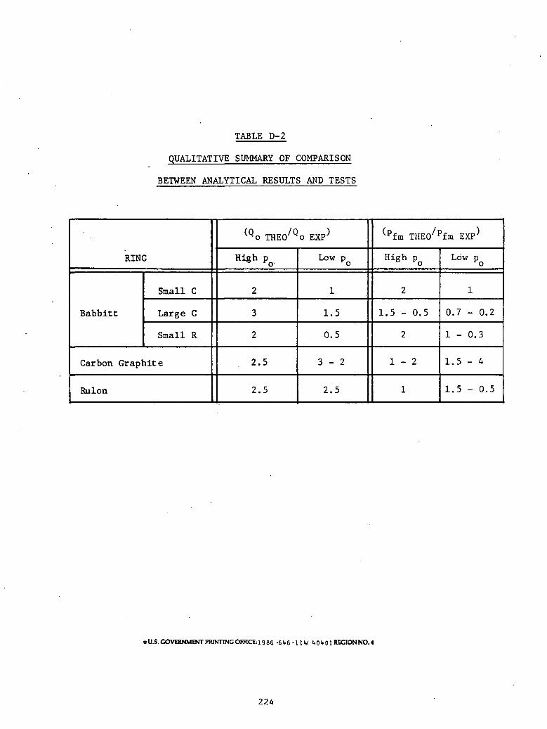
TABLE D-2
QUALITATIVE SUMMARY OF COMPARISON
BETWEEN ANALYTICAL RESULTS AND TESTS
RING
Babbitt
Small C
Large C
Small R
Carbon Graphite
Rulon
^Qo THEO Qo EXP'
High po
2
3
2
2.5
2.5
Low p
1
1.5
0.5
3 - 2
2.5
(pfm THEO/Pfm EXP^
High PQ
2
1.5 - 0.5
2
1 - 2
1
Low p
1
0.7 - 0.2
1 - 0.3
1.5 - 4
1.5 - 0.5
*U.S. GOVERNMENT PRINTING OFFICE:! 9 86 -646-1IV it 0"»01 REGION NO. 4
224
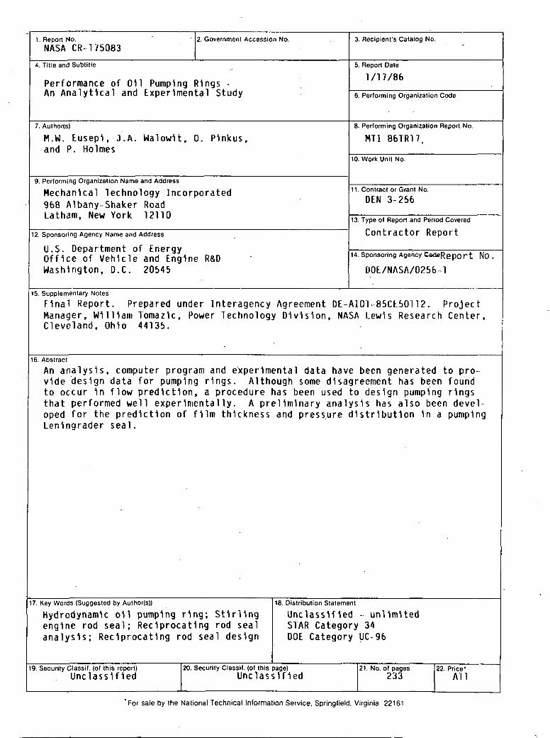
1. Report No.
NASA CR-1750832. Government Accession No. 3. Recipient's Catalog No.
4. Title and Subtitle
Performance of Oil Pumping Rings -An Analytical and Experimental Study
5. Report Date
1/17/86
6. Performing Organization Code
7. Author(s)
M.W. Eusepl, J.A. WalowH, 0. Pinkus,and P. Holmes
8. Performing Organization Report No.
MT1 86TR17
10. Work Unit No.
9. Performing Organization Name and Address
Mechanical Technology Incorporated968 Albany-Shaker RoadLatham, New York 12110
11. Contract or Grant No.
DEN 3-256
12. Sponsoring Agency Name and Address
U.S. Department of EnergyOffice of Vehicle and Engine R&DWashington, D.C. 20545
13. Type of Report and Period Covered
Contractor Report
14. Sponsoring Agency CedeRepOrt NO .
DOE/NASA/0256 1
15. Supplementary Notes
Final Report. Prepared under Interagency Agreement DE-A101-85CE50I12. ProjectManager, William Tomazlc, Power Technology Division, NASA Lewis Research Center,Cleveland, Ohio 44135.
16. Abstract
An analysis, computer program and experimental data have been generated to pro-vide design data for pumping rings. Although some disagreement has been foundto occur 1n flow prediction, a procedure has been used to design pumping ringsthat performed well experimentally. A preliminary analysis has also been devel-oped for the prediction of film thickness and pressure distribution 1n a pumpingLeningrader seal.
7. Key Words (Suggested by Author(s))
HydrodynamU oil pumping ring; Stirlingengine rod seal; Reciprocating rod sealanalysis; Reciprocating rod seal design
18. Distribution Statement
Unclassified - unlimitedSTAR Category 34DOE Category UC-96
9. Security Classif. (of this report)Unclassified
20. Security Classif. (of this page)Unclassified
21. No. of pages233
22. Price'All
"For sale by the National Technical Information Service, Springfield, Virginia 22161