performance of al-rich oxidation resistant coatings for fe
TRANSCRIPT

Performance of Al-richOxidation Resistant
Coatings for Fe-Base AlloysB. A. Pint
Oak Ridge National LaboratoryOak Ridge, TN 37831-6156
Y. ZhangTennessee Technological University
Cookeville, TN 38505-0001
Research sponsored by the U.S. Dept. of EnergyFossil Energy Advanced Research Materials Program

AcknowledgmentsORNLI. Wright, P. TortorelliA. Haynes, K. Cooley - CVD coating fabricationG. Garner, J. Moser, T. Brummett - oxidation experimentsH. Longmire, K. Thomas - metallographyL. Walker - EPMAB. Bates (TTU) - SEM
This research was sponsored by the U. S. Department ofE n e r g y, Fossil Energy Advanced Materials ResearchProgram under contract DE-AC05-00OR22725 with UT-Battelle, LLC.

Coatings for Power GenerationNext generation power plants
Ultra-supercritical steam - up to 760°C from ~590°Chigher efficiency, lower emissions
Coal gasification - low PO2, high PS2high natural gas prices driving interestBenefits of Fe-Al coating:
- resist sulfidation/carburization (well-studied previously)- Al2O3 surface oxide resistant to water vapor
(important in combustor, heat exchanger/recuperator, steam)
Extensive work by Rapp et al. on Fe-Al coatingsBefore coatings are widely employed, criticalquestions need to be answered about benefits:
- maximum temperature for oxidation resistance- need sufficient Al -> diffusion into substrate- thermal expansion mismatch with oxide & substrate- coating effect on substrate mechanical properties

10µm
“thin”
surface~18at%
Experimental ProcedureChemical vapor deposition (CVD) process
selected for controlled laboratory studies, not commercializationsimilar to a well-controlled above-pack process
1-2mm x ≈12 x 20 specimens, 2 per runaustenitic 304L (Fe-18Cr-8Ni) & ferritic T91 (Fe-9Cr-1Mo)ORNL laboratory scale reactorflowing H2-AlClx, 100 Torr, 6h, 900°C or 4h, 1050°C +2h anneal
increase Al activity by adding Cr-Al or Fe-Al alloy in reactor“Thick” coatings ≈40µm Al-rich outer layer, “Thin” ≈5µm Al-rich outer layer
0
5
10
15
20
25
30
35
40
Nor
mal
ized
Com
posit
ion
(at.%
)
0 20 40 60 80 100 120 140 160
Distance from Surface (µm)
Cr
Al
CVD "thick" coat
CVD "thin" coat
Al
Cr
Details in Zhang et al., Surf. Coat. Tech. (2008)
304L

0
1
2
3
4
5
6
0 5 10 15 20 25
Mas
s Cha
nge
(mg/
cm2 )
Time (h)
800°C
Fe-15Al
Fe-20Al
Thin vs. Thick Coatings: SulfidationModel Fe-Al alloys at 800°C in H2-H2O-H2S-Ar
For comparison to coatings, cast Fe-15at%(8wt%)Al& Fe-20%(11wt%)AlFe-15at%Al showed accelerated mass gain in test similar to thin coatingsLow mass gain for Fe-20%AlPrevious work by DeVan and Tortorelli found 18at%Al needed
Higher Al content (“thick”) needed for sulfidation resistance
800°C, 1472°F
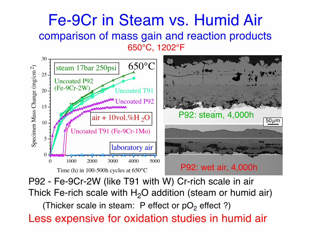
P92 - Fe-9Cr-2W (like T91 with W) Cr-rich scale in airThick Fe-rich scale with H2O addition (steam or humid air)
(Thicker scale in steam: P effect or pO2 effect ?)Less expensive for oxidation studies in humid air
0
5
10
15
20
25
30
Spec
imen
Mas
s Cha
nge
(mg/
cm2 )
0 1000 2000 3000 4000 5000
Time (h) in 100-500h cycles at 650°C
air + 10vol.%H 2O
Uncoated P92
650°C
Uncoated T91 (Fe-9Cr-1Mo)
Uncoated P92(Fe-9Cr-2W)
laboratory air
steam 17bar 250psi
Uncoated T91
Fe-9Cr in Steam vs. Humid Aircomparison of mass gain and reaction products
650°C, 1202°F
50µmP92: steam, 4,000h
P92: wet air, 4,000h

Intrinsic Aluminide Coating ProblemSubstrate-coating thermal expansion mismatch
For coated 304L,Al addition created ferritic inner layer (interdiffusion zone)Three layers have distinct thermal expansion behavior
(high/low/high)Mismatch results in stress sufficient to crack coating
10
14
18
22
Mea
n Th
erm
al E
xpan
sion
ppm
/°C
0 200 400 600 800 1000 1200
Temperature °C
Fe-15Al+Hf
Fe-9Cr-1Mo
Fe-28Al-2Cr+Hf
304L
FeCrAlY
Fe-20Al+Hf
(Fe,Ni)3Al
304L

If CTE mismatch is problem, doesthickness (δ) affect performance?
Thin & thick CVD coatings, 1h cycles, 700°C, humid air
For T91, thinner α-Fe(Al) coating did not show signs of degradationafter 2000 cycles at 700°C
For 304L, thin and thick coatings showing similar performancepossibly less cracking in thinner coating but still penetrated
0.0
0.2
0.4
0.6
0.8
1.0
Spec
imen
Mas
s Cha
nge
(mg/
cm2 )
0 250 500 750 1000 1250 1500 1750 2000
Number of 1h Cycles at 700°C
Fe-9Cr-1Mo
Aluminized Fe-9Cr-1Mo
Aluminized 304L
304L Thick 304L
Thin 304LThick
Thin
Thin 304L
stress = f(Δαcoat-sub)W = f(δcoating)
250µm
Fe-9Cr-1Mocoating
Cu
200µm
thick
(strain energy)
thin

Ferritic Alloy Coating SolutionEliminate CTE mismatch problem
For coated T91:Thick CVD: Outer Fe3Al layer
BUT inner coating & substrate are ferritic
Thin CVD: ~18at.%Al peak surface Al (no aluminide)only α-Fe(Al) phaseNO ΔCTE
10
14
18
22
Mea
n Th
erm
al E
xpan
sion
ppm
/°C
0 200 400 600 800 1000 1200
Temperature °C
Fe-15Al+Hf
Fe-9Cr-1Mo
Fe-28Al-2Cr+Hf
304L
FeCrAlY
Fe-20Al+Hf
Fe3Al
T91T91
“Thin” “Thick”

Creep Testing of P92 (Fe-9Cr-2W)Effect of heat treatment and coating
Specimen with thin coating has better creep resistanceEffect of coating can be modeled as if coated layer absent
Suggests that thin coatings are preferable
0.0E+00
4.0E-04
8.0E-04
1.2E-03
1.6E-03
Cree
p Ra
te (h
-1)
265µ
m P
ack
230µ
m P
ack
40µm
CV
D
650°C110MPa
650°C, 1202°F; gage: 2 x 2 mm
thick thick thin

Standard Oxidation Lifetime ModelLifetime model developed by Quadakkers, Bennett, et al. forODS FeCrAl alloys with 1-3mm cross-sectionsPremise: Calculate time to breakaway (FeOx formation) byknowing total Al reservoir available and rate of Al consumptionModel inputs:- initial Al content (Co)- the critical Al content where Al2O3 will no longer form: (Cb)- the thickness of the specimen (d) and density (ρ)- Al consumption rate (e.g. ktn), t is time,
n=0.5 for parabolic, 1 for linear kinetics
(C0-Cb)/100 • d/2 • ρ = k • tn •
How does this apply to a coating?more complex Al “consumption”: interdiffusion + oxidationC0 becomes a function of the coating thicknessWhat is Cb for a coating?
(mole Al) mole O in Al2O3

Defining a coating failure criterianeed to determine Cb for coating in steam
gas
coating
substrate
oxide
Al supply: coating thickness and starting Al concentrationCoating thickness loss or Al content drop due to:
(1) oxidation/sulfidation: selective formation of reaction product(2) diffusion into substrate
At low temperatures 650-700°C expect loss by (1) << loss by (2)Cb for sulfidation ~20at%Al similar to cast Fe-AlHow low can Al content drop in steam environment?

0.0
0.2
0.4
0.6
0.8
1.0
1.2
Spec
imen
Mas
s Cha
nge
(mg/
cm2 )
0 1000 2000 3000 4000 5000
Time (h) in 100h cycles at 650°C
air + 10vol.%H 2OUncoated P92
Uncoated T91
650°C
Uncoated T91 (Fe-9Cr-1Mo)
Uncoated P92 (Fe-9Cr-2W)
laboratory air
0.00
0.05
0.10
0.15
0.20
0.25
0.30
Spec
imen
Mas
s Cha
nge
(mg/
cm2 )
0 2000 4000 6000 8000 10000 12000
Time (h) in 100h cycles at 650°C
650°Cair + 10vol.%H 2O
T91 Pack coat(triangle)
100h cycles
Uncoated P92
304L Thick CVD coat(square)
T91 Thick CVD coat(circle)
Uncoated T91
T92 Thin CVD coat (circle)
Coating Performance: 650°CCVD or pack cementation coatings
Incubation period before onset of accelerate attack with H2OCoatings show low, parabolic-type mass gains to ~8khLimited interdiffusion at this temperature -> long life!
Last year added “thin” coatings to 650°C test
650°C, 1202°F more commercial coating process

0.0
0.1
0.2
0.3
0.4
0.5
0.6
0.7
Spec
imen
Mas
s Cha
nge
(mg/
cm2 )
0 5000 10000 15000 20000
Time (h) in 100h cycles at 700°C
700°Cair + 10vol.%H 2O
304L Thick coat 304L Thin coat
T91 Thick coat
T91 Thin coatT92 Thin coat (triangles)
T122 Thin coat (triangles)
Coating Performance: 700°CAccelerate failure by increased interdiffusion
Higher mass gains for thin and thick coatings on 304LBreakaway oxidation for thin coating on T91 at ~10,500hThick coatings stopped at 20kh for sectioning
700°C, 1292°F
failure!
100h cyclesSEM: every 2,000h

Al
O
Cr Fe
N
Failed Coating CharacterizedThin coating after 11,000h in humid air at 700°C
Fe-9Cr-1Mo20µm
02468
101214161820
Nor
mal
ized
Al C
onte
nt (a
t.%)
0 50 100 150 200Distance from Surface (µm)
700°C, 11,000h (two profiles)
typical as-coated
T91, CVD Thin coat
Electron probe analysis:Typical Fe-rich oxide nodulesAlN precipitates (0.2at.%N in alloy)~3.5at%Al at surface (Cb)

700°C Performance of thick coatingCoatings stopped after 10 & 20kh in humid air
02468
10121416182022242628
Nor
mal
ized
Al C
onte
nt (a
t.%)
0 100 200 300 400 500 600
Distance from Surface (µm)
20kh700°C
as-coatedT91 CVD Thick coat
10kh700°C
Coating Al profiles on T91:- all for thick coatings- variations in starting thicknessDeformation difference:- ΔCTE difference for 304L
304L substrate(20kh)
T91 substrate(20kh)
T91 substrate
250µm

Prediction COSIM COSIM COSIM Heckel ActualMethod dependent indep. FeAl indep. FeCrAl (diffusion test)
Surface (at.%) 19 16 17 19 18%Al
Thickness (µm) 310 438 428 356 320 µm
Lifetime:(sulfidation)assuming 20% 6.8 kh 5.0 kh 5.6 kh 7.5 kh ?(wet air)assuming 8% 187 57 66 104 ?assuming 3.5% 639 219 248 592 kh ??
(>2mm depth!)
Lifetime predictions at 700°CUsing 10kh observations for thick coatings on Fe-Cr
Sulfidation - insufficient life at 700°C, need to drop to ~625°CWet air - high probability of thick coating making 100kh lifetime
Model details in Zhang et al., Mater. Corr. 58 (2007)

Coating Performance: 800°CThick coatings tested to accelerate failure
304L Degradation:Macroscopic deformation (304L dog bone)Higher mass gain (consumed outer layer)T91 specimen completed 6 and 20kh
no coating failure observedsome scale spallation (SEM)
0.0
0.5
1.0
1.5
2.0
2.5
Spec
imen
Mas
s Cha
nge
(mg/
cm2 )
0 5000 10000 15000 20000
Time (h) in 100h cycles at 800°C
800°Cair + 10vol.%H 2O
100h cycles
AluminizedFe-9Cr (lab.)
UncoatedFe-9Cr-1Mo
Aluminized304L (comm.)
Aluminized304L (lab.)
AluminizedFe-9Cr (comm.)
AluminizedFe-9Cr (comm.)
Cu-plating
commercial T91(6kh)
commercial 304L(6kh)
250µm
50µm
FeO Cu-plating
inner layer
commercial T91(20kh)

0
2
4
6
8
10
12
14
16
18
20
Spec
imen
Mas
s Cha
nge
(mg/
cm2 )
0 4000 8000 12000 16000 20000
Time (h) in 100h cycles at 800°C
800°Cair + 10vol.%H 2O
Aluminized Fe-9Cr
100h cycles
UncoatedFe-9Cr-1Mo
250µm
20kh Coating CharacterizedThick coating on T91 in humid air at 800°C
50µm
commercial T91(20kh)
20kh specimen:No macroscopic deformationLow mass gain
- but outer layer local breachPorous coating layer
- Al loss due to scale spallation
FeOx

Al
O
Cr Fe
N
20kh Coating CharacterizedThick coating on T91 in humid air at 800°C
Fe-9Cr-1Mo20µm
02468
10121416182022242628
Nor
mal
ized
Al C
onte
nt (a
t.%)
0 250 500 750 1000 1250 1500 1750
Distance from Surface (µm)
20kh, 800°C(diamonds)
as-coated (typical)(circles)
T91 CVD Thick coat
6kh, 800°C(triangles)
Electron probe analysis:Typical Fe-rich oxide nodulesLocal alumina scale piecesAlN precipitates (0.2at.%N in alloy)

Coating Performance: 800°CThin coating testing to failure
Final series started last year, failures to date:Thin coating on T92 (2,500h stop last year)Thin coating on T91 (2,200h stop last week)Thin coating on 304L (problem at 500h, maybe bad coating)
Still running: T122 (higher Cr), 316SS
-1.5
-1.0
-0.5
0.0
0.5
1.0
1.5
2.0
2.5
Spec
imen
Mas
s Cha
nge
(mg/
cm2 )
0 500 1000 1500 2000 2500 3000Time (h) in 100h cycles at 800°C
800°C, 100h cyclesair + 10vol.%H 2O
UncoatedFe-9Cr-1Mo
Thin CVDT92
Thick CVDFe-9Cr-1Mo
UncoatedFe-9Cr-2W
Thin CVD T91
Thin CVD T122
Thin CVD316SS
failure last week!
200µm
SEM plan view

Al
O
Cr Si
N
Failed Coating at 800°CThin coating on P92 after 2,800h in humid air
Fe-9Cr-2W20µm
0.0
0.5
1.0
1.5
2.0
2.5
3.0
3.5
4.0
Nor
mal
ized
Al C
onte
nt (a
t.%)
0 50 100 150 200Distance from Surface (µm)
700°C, 11,000h (two profiles)
typical as-coatedT91, CVD Thin coat
800°C, 2,800h (two profiles)
Electron probe analysis:Area away from FeO nodulesLarge AlN precipitates (N in alloy)~0.7at%Al near surface (Cb)

0
5
10
15
20
25
30
35
40
Nor
mal
ized
Com
posit
ion
(at.%
)
0 20 40 60 80
Distance from Surface (µm)
Cr
Al
2kh, 800°C
As-deposited "thin coat"
Al
Cr
20µm
50µm
Failed Coating at 800°CThin coating on 304L after 2,000h in humid air
Electron probe analysis:Expected: Large AlN precipitates (N in alloy)Unexpected: Early failure and little Al remaining in coating
Maybe a poor quality coating (compare to 316SS)
304L
FeOx

0
5
10
15
20
25
30
35
Nor
mal
ized
Al C
onte
nt (a
t.%)
0 100 200 300 400Distance from Surface (µm)
304L CVD Thick coat
6kh, 800°C
as-coated (typical)
10kh, 800°C
Future work: austenitic modelFour component system (Fe, Ni, Cr, Al) + two phase
304L: COSIM model missing diffusion termsThree phase system (β-(Fe,Ni)Al+ ferrite + substrate)
Observations: Thinner starting coating than on T91Slower Al diffusion: inhibited by phase transformation~4.5at%Al remained in inner layer (+ ~18%Cr) - equilibrium?
0
2
4
6
8
1012
1416
18
20
Nor
mal
ized
Al C
onte
nt (a
t.%)
0 100 200 300 400 500 600
Distance from Surface (µm)
T91 6kh, 800°C
T91 as-coated(peak 26%)
CVD Thick coat
304L 6kh, 800°C
304L as-coated(peak 35%)

Incomplete: Effect of CCr on CbThin coatings at 700°C in humid air
Similar Cr content in coating as in Fe-base substrateCr known to improve selective Al oxidation: “third element”Much longer lifetime for 304L(18Cr) at 700°C (>20kh)
T91(~9Cr) failed at <11khVarious Fe-Cr (9-12Cr) substrates being tested
0.0
0.1
0.2
0.3
0.4
0.5
Spec
imen
Mas
s Cha
nge
(mg/
cm2 )
0 3000 6000 9000 12000 15000 18000 21000
Time (h) in 100h cycles at 700°C
700°Cair + 10vol.%H 2O
304L (18Cr)Thin CVD
T91 (9Cr) Thin CVD
0.0
0.1
0.2
0.3
Spec
imen
Mas
s Cha
nge
(mg/
cm2 )
0 2000 4000 6000 8000 10000
Time (h) in 100h cycles at 700°C
700°Cair + 10vol.%H 2O
T92 (9Cr)
T122 (11Cr)
T91 (9Cr)

SummaryOxidation performance of thick and thin CVD aluminidecoatings on ferritic (T91) and austenitic (304L) substrateshave been evaluated at 650°-800°C in humid air.
CTE mismatch problemAustenitic alloys: 3 layers aluminide/ferritic/austenitic
- coating deformation and cracking observed on 304LFerritic alloys: Fe3Al/ferritic mismatch can cause crackingSolution:“Thin” coatings T91: no high CTE intermetallic Fe-Al phase
Higher temperatures (700°-800°C) used to induce failures.Failure of thin CVD coating on Fe-9Cr in wet air:
- 700°C: 11kh Cb~3.5at%- 800°C: 2.8kh Cb~0.7at%
Accurate Cb needed for lifetime model- determine Cb as f(temperature, CCr, steam, etc.)