performance monitoring — case studies of tracks stabilised ... · pdf fileangular...
TRANSCRIPT

FMGM 2015 – PM Dight (ed.) © 2015 Australian Centre for Geomechanics, Perth, ISBN 978-0-9924810-2-5
FMGM 2015, Sydney, Australia 233
Performance monitoring — case studies of tracks stabilised by geosynthetic grids and prefabricated vertical drains
B Indraratna University of Wollongong, Australia
SK Navaratnarajah University of Wollongong, Australia
S Nimbalkar University of Wollongong, Australia
C Rujikiatkamjorn University of Wollongong, Australia
T Neville Australian Rail Track Corporation Ltd, Australia
Abstract
This paper focusses on assessing the performance of rail track through field trials conducted in the towns of Bulli, Singleton and Sandgate in the state of New South Wales (NSW), Australia. In Bulli and Singleton, different types of geosynthetics (geogrid, geotextile and geocomposite) were installed to investigate their relative advantages in relation to various aperture sizes and types of subgrade. A key objective of this study was to evaluate the effect of these artificial inclusions on the vertical and lateral track deformation as the large-scale laboratory tests provided evidence that grids reduce particle breakage by restraining the movement of aggregates and by increasing the effective confining pressure such that excessive dilation is curtailed. The geogrids were more affective at controlling displacement when the track was constructed on a soft subgrade such as estuarine soil.
With the tracks constructed directly onto estuarine planes consisting of the inevitable deep and saturated soft clay and silt deposits at Sandgate, prefabricated vertical drains (PVDs) were installed to a depth of less than 8 m to swiftly consolidate the soft upper clay stratum thereby helping resist long term track settlement while increasing the bearing capacity and shear strength. A sophisticated finite element program was developed to capture the behaviour of ballast, subballast and subgrade under cyclic loading via a coupled flow-deformation analysis capable of predicting the vertical and lateral displacement of the tracks, as well as the build-up of excess porewater pressure in the soft estuarine clay. The field data provided by the track owner (one year after the initial design and FEM predictions) proved that PVDs improved track stability by reducing the lateral movements of the subgrade while increasing its load bearing capacity.
1 Introduction
In Australia, the rail transportation system plays a significant role in the conveyance of bulk freight and passengers. The rail track structure is categorised into two parts: (i) superstructure consisting of rail, fastening systems, and sleepers; and (ii) substructure consisting of ballast, capping, structural fill, and subgrade. The engineering behaviour of ballast is one of the most important aspects governing the stability and performance of a railway track because its progressive degradation under heavy cyclic loads applied by freight and passenger trains contributes largely to overall track deformation (Indraratna et al. 2011). In order to improve track performance and reduce the cost of maintenance, geosynthetic grids can be beneficial, and if waste ballast is cleaned, sieved, and then re-used in track reinforced with geosynthetics, it is also an economically feasible alternative.
The use of geosynthetics for drainage and internal track confinement, as well as a separation layer between the ballast and subballast, is highly desirable (Raymond 2002; Brown et al. 2007; Indraratna et al. 2007; 2010a; 2010b; 2013; 2014b; 2014c). The results of large-scale cyclic triaxial tests indicated that a layer of geocomposite (biaxial geogrid bonded with nonwoven geotextiles) stabilised recycled ballast much more
https://papers.acg.uwa.edu.au/p/1508_13_Navaratnarajah/

Performance monitoring — case studies of tracks stabilised by geosynthetic grids B Indraratna et al. and prefabricated vertical drains
234 FMGM 2015, Sydney, Australia
effectively than geogrids, and also prevented ballast fouling due to the upward migration of fines from layers of subballast and subgrade (Indraratna & Salim 2003). Both the type of reinforcement and its layout played a vital role in improving the performance of the track (Indraratna & Nimbalkar 2013). The results of large-scale tests clearly illustrated how shock mats (shock absorbing rubber mats) improved the performance of ballast subjected to impact blows (Nimbalkar et al. 2012) as well as number of cyclic load applications (Indraratna et al. 2014a). A field trial was conducted on a section of instrumented railway track at Bulli, NSW, Australia to study the effectiveness of a geocomposite installed at the ballast-capping interface. The relative performance of moderately graded recycled ballast compared to the very uniform fresh ballast traditionally used, was also evaluated. Another field trial was conducted at Singleton, NSW, Australia, to study the relative advantages of different types of geosynthetics (geogrids, geocomposite) on track performance.
The fast development of many coastal regions of Australia on soft clay deposits with low bearing capacity, low permeability and high compressibility means that these undesirable geotechnical properties would have a detrimental effect on the long term stability and serviceability of the transport infrastructure, particularly highways and rail embankments (Johnson 1970). These soft clay deposits with high volumes of plastic clays can sustain high excess pore-water pressures during static and cyclic loading, but they still need appropriate ground improvement. The preloading soft clay with incorporation of vertical drains is one of the most popular methods used to induce consolidation thereby increasing the shear strength of soft soil and controlling its post-construction settlement. Often the consolidation time needed to achieve the desired improvement in settlement or shear strength characteristics may take too long due to low permeability (Holtz 1987; Indraratna et al. 1994). However, by using PVDs, the drainage path is shortened from the thickness of the soil layer to the radius of the drain influence zone, which accelerates consolidation (Hansbo 1981). This system has been used to improve the properties of foundation soil for railway embankments, airports, and highways (Li & Rowe 2001). Although train loads can be carried by ballast and subballast to predetermined depths, a significant amount of applied load is still sustained within several metres of the underlying subgrade, and therefore relatively short PVDs (between 5 and 8 m in length) can easily dissipate cyclically induced pore pressures. Soil stabilisation using relatively short drains for a rail track construction was conducted at the Sandgate Rail Grade Separation Project near Newcastle. In this case study, a sophisticated finite-element code was developed to capture the associated settlement and lateral displacements.
2 Case study 1 — Instrumented track at Bulli
The performance of geosynthetically stabilised unused (fresh) and recycled ballasted track was studied at instrumented track sections located between two turnouts at Bulli, NSW (Indraratna et al. 2010a). A site exploration program to assess the geological conditions indicated that the stiff, overconsolidated silty clay subgrade was strong enough to support moving train loads (Robertson 1990). The underlying bedrock was about 2.3 to 2.8 m below the ground level, and consisted of highly weathered sandstone.
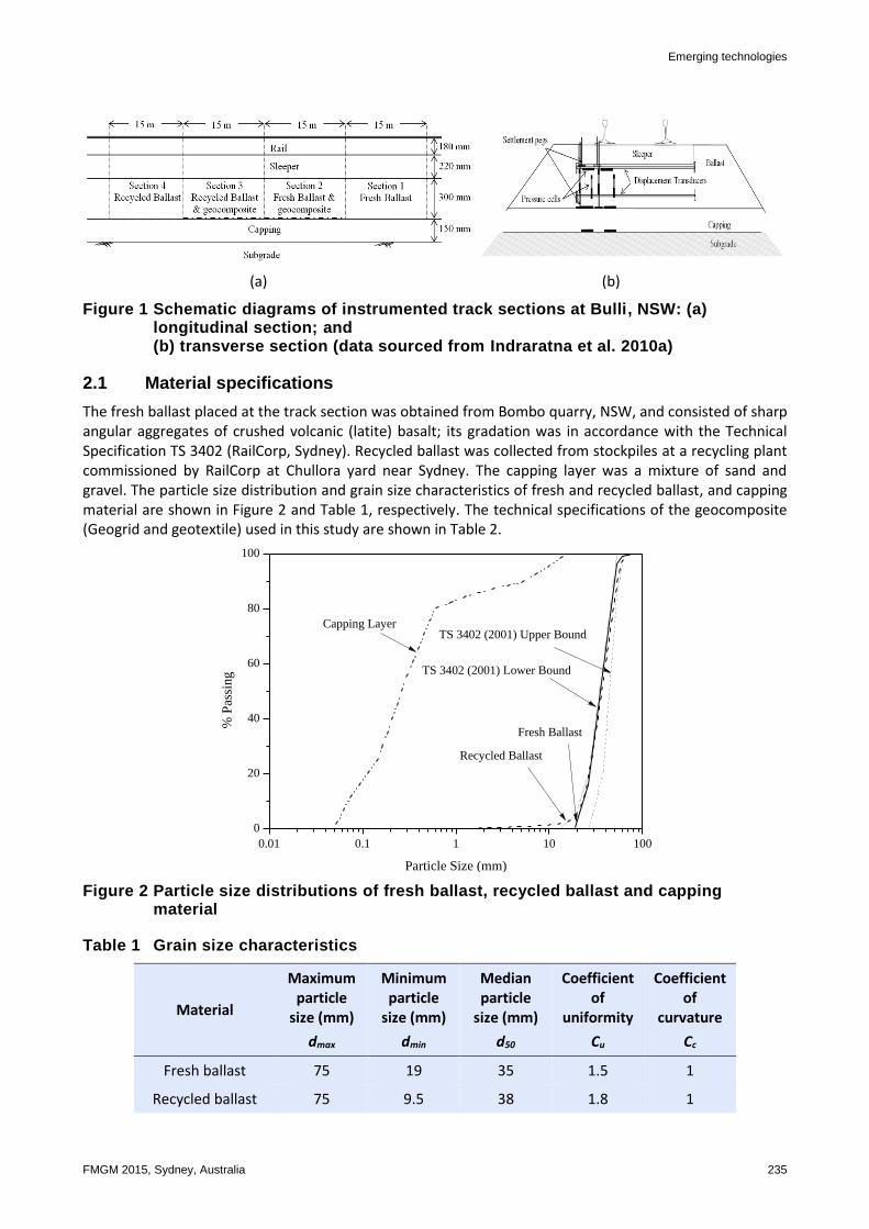
A 60 m length of instrumented track, consisting of four 15 m long sections, was investigated in this field trial to help understand the stress induced by the moving trains and corresponding vertical and lateral deformation, as well as the benefits of using geosynthetic to improve the performance of ballasted track. A longitudinal and a transverse section of the instrumented track are shown in Figures 1(a) and (b), respectively. Sections 1 and 2 were built using fresh ballast and Sections 3 and 4 were built with recycled ballast. A geocomposite layer at the ballast-capping interface was placed at Sections 2 and 3 to study the relative performance of track with this geosynthetic inclusion. The overall granular layer consisted of 300 mm of ballast and a 150 mm capping layer. The geocomposite layer was a combination of biaxial geogrid and non-woven type polypropylene geotextile. This type of combined geosynthetic layer can produce much better stabilisation and prevent ballast fouling due to migration of subgrade and capping fines to the ballast layer (Indraratna et al. 2011).
Emerging technologies
FMGM 2015, Sydney, Australia 235
(a) (b)
Figure 1 Schematic diagrams of instrumented track sections at Bulli, NSW: (a) longitudinal section; and (b) transverse section (data sourced from Indraratna et al. 2010a)
2.1 Material specifications
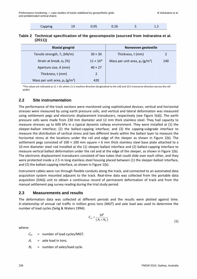
The fresh ballast placed at the track section was obtained from Bombo quarry, NSW, and consisted of sharp angular aggregates of crushed volcanic (latite) basalt; its gradation was in accordance with the Technical Specification TS 3402 (RailCorp, Sydney). Recycled ballast was collected from stockpiles at a recycling plant commissioned by RailCorp at Chullora yard near Sydney. The capping layer was a mixture of sand and gravel. The particle size distribution and grain size characteristics of fresh and recycled ballast, and capping material are shown in Figure 2 and Table 1, respectively. The technical specifications of the geocomposite (Geogrid and geotextile) used in this study are shown in Table 2.
Figure 2 Particle size distributions of fresh ballast, recycled ballast and capping material
Table 1 Grain size characteristics
Material
Maximum particle
size (mm)
dmax
Minimum particle
size (mm)
dmin
Median particle
size (mm)
d50
Coefficient of
uniformity
Cu
Coefficient of
curvature
Cc
Fresh ballast 75 19 35 1.5 1
Recycled ballast 75 9.5 38 1.8 1
0.01 0.1 1 10 100
0
20
40
60
80
100
TS 3402 (2001) Upper Bound
TS 3402 (2001) Lower Bound
Capping Layer
Recycled Ballast
Fresh Ballast
% P
assi
ng
Particle Size (mm)
Performance monitoring — case studies of tracks stabilised by geosynthetic grids B Indraratna et al. and prefabricated vertical drains
236 FMGM 2015, Sydney, Australia
Capping 19 0.05 0.26 5 1.2
Table 2 Technical specification of the geocomposite (sourced from Indraratna et al. (2011))
Biaxial geogrid Nonwoven geotextile
Tensile strength, Tu (kN/m) 30 × 30 Thickness, t (mm) 2
Strain at break, εb (%) 11 × 10* Mass per unit area, ρa (g/m2) 140
Aperture size, A (mm) 40 × 27
Thickness, t (mm) 2
Mass per unit area, ρa (g/m2) 420
*The values are indicated as 11 × 10; where 11 is machine direction (longitudinal to the roll) and 10 is transverse direction (across the roll width)
2.2 Site instrumentation
The performance of the track sections were monitored using sophisticated devices; vertical and horizontal stresses were measured by using earth pressure cells, and vertical and lateral deformation was measured using settlement pegs and electronic displacement transducers, respectively (see Figure 5(d)). The earth pressure cells were made from 230 mm diameter and 12 mm thick stainless steel. They had capacity to measure stresses up to 600 kPa in a typical dynamic railway environment. They were installed at (1) the sleeper-ballast interface; (2) the ballast-capping interface; and (3) the capping-subgrade interface to measure the distribution of vertical stress and two different levels within the ballast layer to measure the horizontal stress at the locations under the rail and edge of the sleeper as shown in Figure 1(b). The settlement pegs consisted of 100 × 100 mm square × 6 mm thick stainless steel base plate attached to a 10 mm diameter steel rod installed at the (1) sleeper-ballast interface and (2) ballast-capping interface to measure vertical ballast deformation under the rail and at the edge of the sleeper, as shown in Figure 1(b). The electronic displacement transducers consisted of two tubes that could slide over each other, and they were protected inside a 2.5 m long stainless steel housing placed between (1) the sleeper-ballast interface, and (2) the ballast-capping interface, as shown in Figure 1(b).
Instrument cables were run through flexible conduits along the track, and connected to an automated data acquisition system mounted adjacent to the track. Real-time data was collected from the portable data acquisition (DAQ) unit to obtain a continuous record of permanent deformation of track and from the manual settlement peg survey reading during the trial study period.
2.3 Measurements and results
The deformation data was collected at different periods and the results were plotted against time. A relationship of annual rail traffic in million gross tons (MGT) and axle load was used to determine the number of load cycles (Selig & Waters 1994):
610m
t a
CA N (1)
where:
Cm = number of load cycles/MGT.
At = axle load in tons.
Na = number of axles/load cycle.

Emerging technologies
FMGM 2015, Sydney, Australia 237
For example, considering an annual tonnage of 60 MGT of traffic, and 4 axles per load cycle with an axle load of 25 tons gives 600,000 load cycles per year for 60 MGT track. By using Equation 1, the results obtained are plotted against number of load cycles.
2.3.1 Maximum traffic induced stresses
The maximum cyclic vertical (v) and horizontal (h) stresses induced from train wheels passing over the instrumented locations were recorded from sections with fresh ballast (Section 1). Table 3 shows the maximum cyclic stresses at the interfaces under the rail for two different axle loads (20.5 ton axle load passenger train with an 82 class locomotive and a coal train with 100 ton wagons).
It was evident that higher vertical cyclic stresses were induced within the ballast layer but they diminished significantly below the capping layer while the reductions of horizontal stresses at depth were only
marginal. It was also evident from the results shown in Table 3 that v and h had increased for higher axle loads at the ballast and capping layers, as was expected. This suggested that the higher axle load of the coal train imposed higher stresses that increased the deformation and degradation of ballast. It also implied that more frequent track maintenance is needed for coal trains compared to passenger trains.
Table 3 Maximum cyclic stresses at test section 1 (data sourced from Indraratna et al. 2010a)
Measured location Under the rail
Axle load
20.5 ton 25 ton
(passenger train (coal train
82 class locomotive) 100 tons wagons)
Stress (kPa) Vertical (v) Horizontal (h) Vertical (v) Horizontal (h)
Sleeper-ballast 238 25 293 46
Ballast-capping 63 18 86 26
2.3.2 Ballast deformation
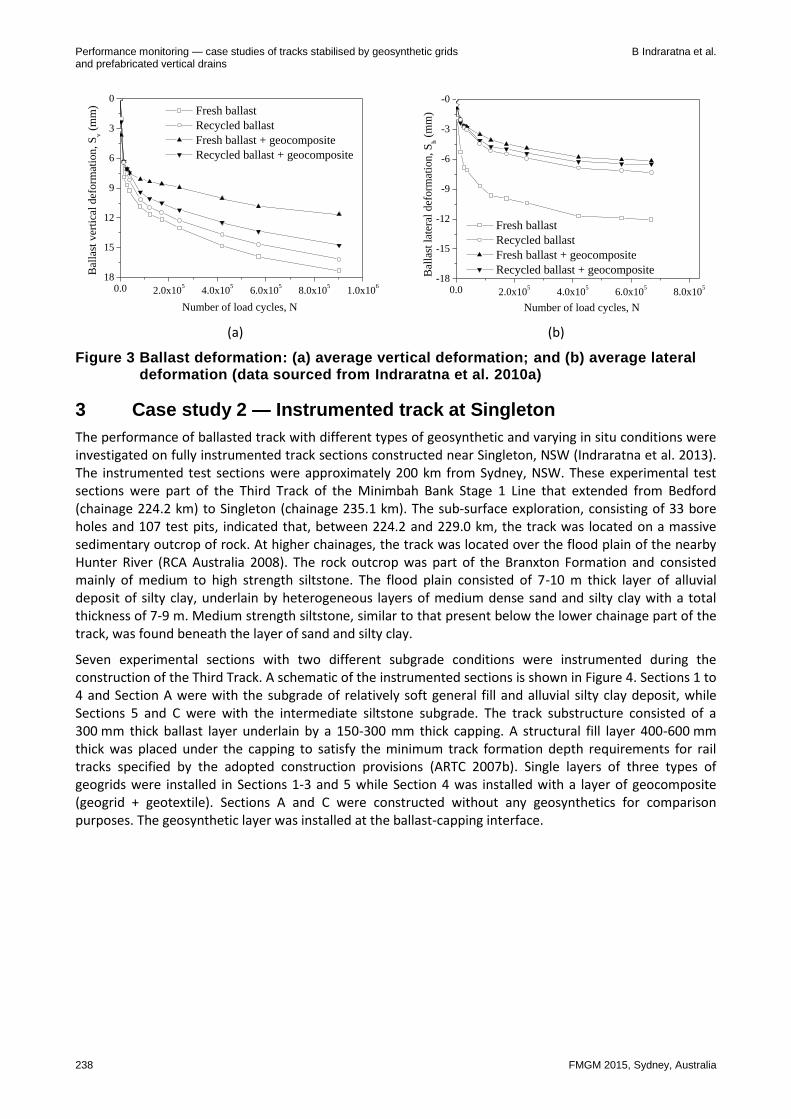
The average vertical and lateral deformation was calculated from the mean values of deformation measured between the sleeper and ballast, and between the ballast and capping interfaces. These values were plotted with the number of load cycles (N), as calculated from Equation 1, and are shown in Figure 3. The recycled ballast showed improved performance compared to fresh ballast in terms of deformation because the recycled ballast consisted of moderately graded particles with less angularity (corners already broken from previous use) and very minimal corner breakage compared to the fresh ballast with uniformly graded particles with very sharp angular corners. The results shown in Figure 3 indicate the potential benefits of using a geocomposite at the ballast-capping interface of a rail track, because it reduced the vertical deformation of fresh and recycled ballast by 33 and 9%, respectively, while reducing the lateral deformation of fresh and recycled ballast by 49 and 11%, respectively. The apertures of the geogrid offered a strong mechanical interlock with the ballast, and formed an increased frictional interlock. The ability of geosynthetics to reduce the rate of ballast deterioration is of benefit to the railway industry because the cost of installation is low compared to the substantial financial benefits generated by an extended life span of the track, and reduced maintenance due to more resilient behaviour by the ballast.
Performance monitoring — case studies of tracks stabilised by geosynthetic grids B Indraratna et al. and prefabricated vertical drains
238 FMGM 2015, Sydney, Australia
(a) (b)
Figure 3 Ballast deformation: (a) average vertical deformation; and (b) average lateral deformation (data sourced from Indraratna et al. 2010a)
3 Case study 2 — Instrumented track at Singleton
The performance of ballasted track with different types of geosynthetic and varying in situ conditions were investigated on fully instrumented track sections constructed near Singleton, NSW (Indraratna et al. 2013). The instrumented test sections were approximately 200 km from Sydney, NSW. These experimental test sections were part of the Third Track of the Minimbah Bank Stage 1 Line that extended from Bedford (chainage 224.2 km) to Singleton (chainage 235.1 km). The sub-surface exploration, consisting of 33 bore holes and 107 test pits, indicated that, between 224.2 and 229.0 km, the track was located on a massive sedimentary outcrop of rock. At higher chainages, the track was located over the flood plain of the nearby Hunter River (RCA Australia 2008). The rock outcrop was part of the Branxton Formation and consisted mainly of medium to high strength siltstone. The flood plain consisted of 7-10 m thick layer of alluvial deposit of silty clay, underlain by heterogeneous layers of medium dense sand and silty clay with a total thickness of 7-9 m. Medium strength siltstone, similar to that present below the lower chainage part of the track, was found beneath the layer of sand and silty clay.
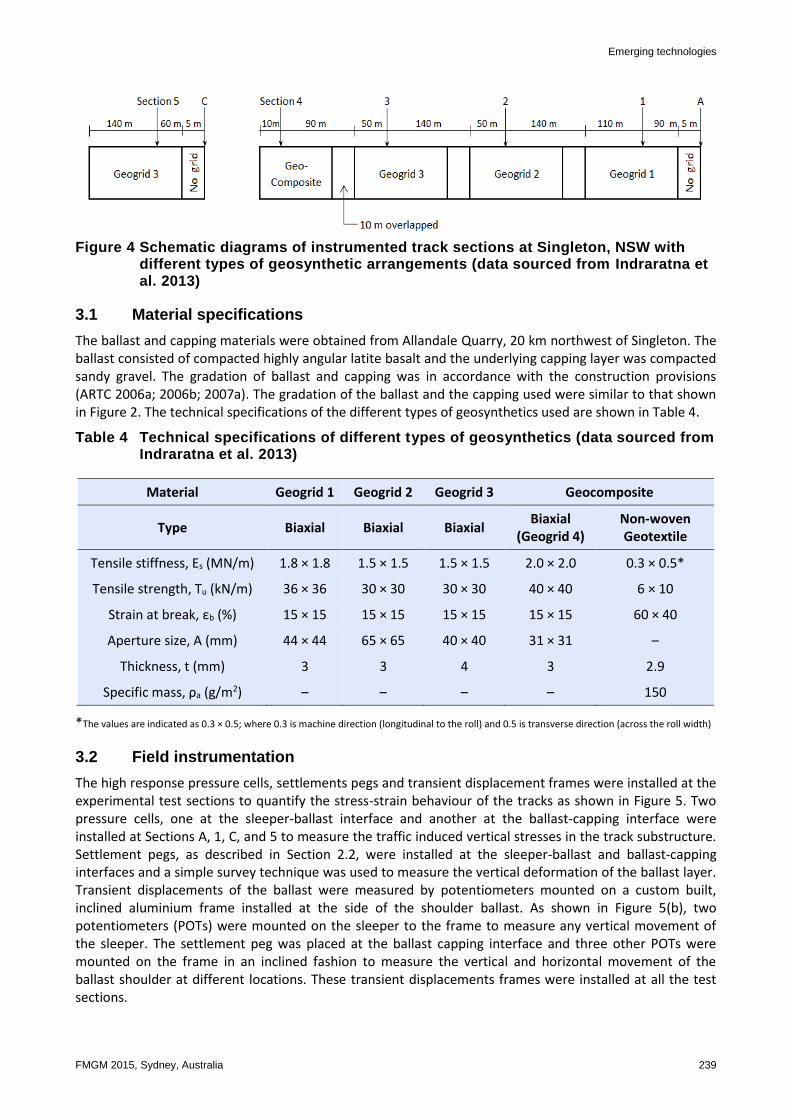
Seven experimental sections with two different subgrade conditions were instrumented during the construction of the Third Track. A schematic of the instrumented sections is shown in Figure 4. Sections 1 to 4 and Section A were with the subgrade of relatively soft general fill and alluvial silty clay deposit, while Sections 5 and C were with the intermediate siltstone subgrade. The track substructure consisted of a 300 mm thick ballast layer underlain by a 150-300 mm thick capping. A structural fill layer 400-600 mm thick was placed under the capping to satisfy the minimum track formation depth requirements for rail tracks specified by the adopted construction provisions (ARTC 2007b). Single layers of three types of geogrids were installed in Sections 1-3 and 5 while Section 4 was installed with a layer of geocomposite (geogrid + geotextile). Sections A and C were constructed without any geosynthetics for comparison purposes. The geosynthetic layer was installed at the ballast-capping interface.
0.0 2.0x10⁵
4.0x10⁵
6.0x10⁵
8.0x10⁵
1.0x10⁶
18
15
12
9
6
3
0
Fresh ballast
Recycled ballast
Fresh ballast + geocomposite
Recycled ballast + geocomposite
Bal
last
ver
tica
l def
orm
atio
n, S
v (
mm
)
Number of load cycles, N
0.0 2.0x10⁵
4.0x10⁵
6.0x10⁵
8.0x10⁵
-18
-15
-12
-9
-6
-3
-0
Fresh ballast
Recycled ballast
Fresh ballast + geocomposite
Recycled ballast + geocompositeBal
last
lat
eral
def
orm
atio
n, S
h (
mm
)
Number of load cycles, N
Emerging technologies
FMGM 2015, Sydney, Australia 239
Figure 4 Schematic diagrams of instrumented track sections at Singleton, NSW with different types of geosynthetic arrangements (data sourced from Indraratna et al. 2013)
3.1 Material specifications
The ballast and capping materials were obtained from Allandale Quarry, 20 km northwest of Singleton. The ballast consisted of compacted highly angular latite basalt and the underlying capping layer was compacted sandy gravel. The gradation of ballast and capping was in accordance with the construction provisions (ARTC 2006a; 2006b; 2007a). The gradation of the ballast and the capping used were similar to that shown in Figure 2. The technical specifications of the different types of geosynthetics used are shown in Table 4.
Table 4 Technical specifications of different types of geosynthetics (data sourced from Indraratna et al. 2013)
Material Geogrid 1 Geogrid 2 Geogrid 3 Geocomposite
Type Biaxial Biaxial Biaxial Biaxial
(Geogrid 4) Non-woven Geotextile
Tensile stiffness, Es (MN/m) 1.8 × 1.8 1.5 × 1.5 1.5 × 1.5 2.0 × 2.0 0.3 × 0.5*
Tensile strength, Tu (kN/m) 36 × 36 30 × 30 30 × 30 40 × 40 6 × 10
Strain at break, εb (%) 15 × 15 15 × 15 15 × 15 15 × 15 60 × 40
Aperture size, A (mm) 44 × 44 65 × 65 40 × 40 31 × 31 –
Thickness, t (mm) 3 3 4 3 2.9
Specific mass, ρa (g/m2) – – – – 150
*The values are indicated as 0.3 × 0.5; where 0.3 is machine direction (longitudinal to the roll) and 0.5 is transverse direction (across the roll width)
3.2 Field instrumentation
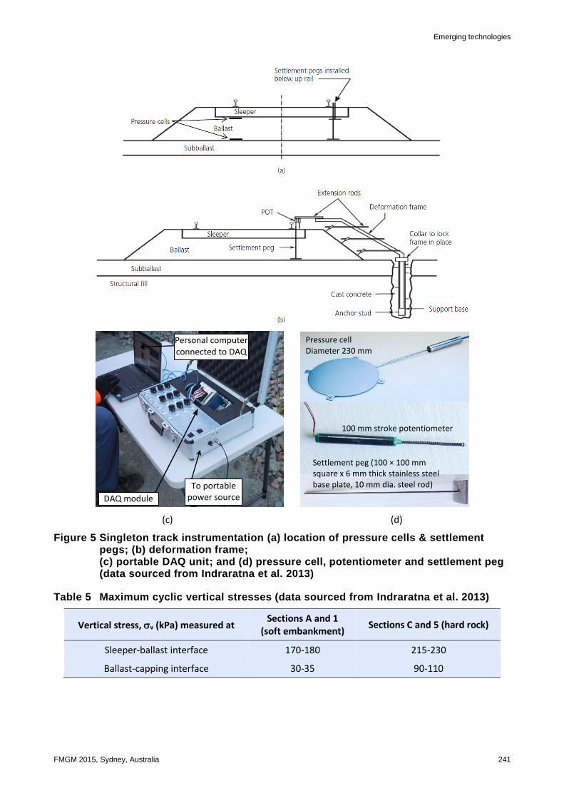
The high response pressure cells, settlements pegs and transient displacement frames were installed at the experimental test sections to quantify the stress-strain behaviour of the tracks as shown in Figure 5. Two pressure cells, one at the sleeper-ballast interface and another at the ballast-capping interface were installed at Sections A, 1, C, and 5 to measure the traffic induced vertical stresses in the track substructure. Settlement pegs, as described in Section 2.2, were installed at the sleeper-ballast and ballast-capping interfaces and a simple survey technique was used to measure the vertical deformation of the ballast layer. Transient displacements of the ballast were measured by potentiometers mounted on a custom built, inclined aluminium frame installed at the side of the shoulder ballast. As shown in Figure 5(b), two potentiometers (POTs) were mounted on the sleeper to the frame to measure any vertical movement of the sleeper. The settlement peg was placed at the ballast capping interface and three other POTs were mounted on the frame in an inclined fashion to measure the vertical and horizontal movement of the ballast shoulder at different locations. These transient displacements frames were installed at all the test sections.

Performance monitoring — case studies of tracks stabilised by geosynthetic grids B Indraratna et al. and prefabricated vertical drains
240 FMGM 2015, Sydney, Australia
Electrical analogue signals from the pressure cells and potentiometers were obtained using a portable DAQ unit consisted of a module working in parallel with a mobile personal computer as shown in Figure 5(c). A 12 V automotive battery provided a direct current power supply to the DAQ module. The module provided electrical excitations and received signals from the instruments. These signals were converted into a digital format and then later in real time in the mobile computer. The raw data was filtered to reduce background noise. The DAQ module was configured and controlled by a computer program written in the LabView environment. All the field measurements were obtained at a frequency of 2,000 Hz.
3.3 Measurements and results
Base readings for the field instrumentation were taken immediately after the instruments were installed. The ongoing field measurements were obtained daily for three days, weekly for three weeks, monthly for three months and then quarterly for three quarters. The numbers of load cycles were calculated using Equation 1, as described in the previous section. A total traffic tonnage of 64 MGT on the third track was reported by Newcastle Geotech (2011) during the period of measurements, with most of traffic being coal trains (four axles with axle loads between 25 and 30 t).
3.3.1 Maximum traffic induced stresses
The maximum cyclic vertical stresses (v) induced from the passage of trains with an axle load of 30 t and travelling at 40 km/h were measured at different test sections, and are shown in Table 5. As expected, the stresses at sleeper-ballast interface were higher than at the ballast-capping interface. It was also evident from these test results that the cyclic induced stresses were higher for the hard rock subgrade at Sections C and 5 compared to the soft embankment at Sections A and 1.
Emerging technologies
FMGM 2015, Sydney, Australia 241
(c) (d)
Figure 5 Singleton track instrumentation (a) location of pressure cells & settlement pegs; (b) deformation frame; (c) portable DAQ unit; and (d) pressure cell, potentiometer and settlement peg (data sourced from Indraratna et al. 2013)
Table 5 Maximum cyclic vertical stresses (data sourced from Indraratna et al. 2013)
Vertical stress, v (kPa) measured at Sections A and 1
(soft embankment) Sections C and 5 (hard rock)
Sleeper-ballast interface 170-180 215-230
Ballast-capping interface 30-35 90-110
DAQ module
To portable power source
Personal computer connected to DAQ
unit
Pressure cell Diameter 230 mm
100 mm stroke potentiometer
Settlement peg (100 × 100 mm square x 6 mm thick stainless steel base plate, 10 mm dia. steel rod)
Performance monitoring — case studies of tracks stabilised by geosynthetic grids B Indraratna et al. and prefabricated vertical drains
242 FMGM 2015, Sydney, Australia
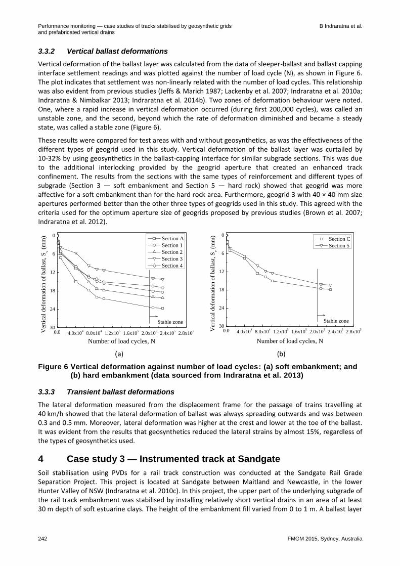
3.3.2 Vertical ballast deformations
Vertical deformation of the ballast layer was calculated from the data of sleeper-ballast and ballast capping interface settlement readings and was plotted against the number of load cycle (N), as shown in Figure 6. The plot indicates that settlement was non-linearly related with the number of load cycles. This relationship was also evident from previous studies (Jeffs & Marich 1987; Lackenby et al. 2007; Indraratna et al. 2010a; Indraratna & Nimbalkar 2013; Indraratna et al. 2014b). Two zones of deformation behaviour were noted. One, where a rapid increase in vertical deformation occurred (during first 200,000 cycles), was called an unstable zone, and the second, beyond which the rate of deformation diminished and became a steady state, was called a stable zone (Figure 6).
These results were compared for test areas with and without geosynthetics, as was the effectiveness of the different types of geogrid used in this study. Vertical deformation of the ballast layer was curtailed by 10-32% by using geosynthetics in the ballast-capping interface for similar subgrade sections. This was due to the additional interlocking provided by the geogrid aperture that created an enhanced track confinement. The results from the sections with the same types of reinforcement and different types of subgrade (Section 3 — soft embankment and Section 5 — hard rock) showed that geogrid was more affective for a soft embankment than for the hard rock area. Furthermore, geogrid 3 with 40 × 40 mm size apertures performed better than the other three types of geogrids used in this study. This agreed with the criteria used for the optimum aperture size of geogrids proposed by previous studies (Brown et al. 2007; Indraratna et al. 2012).
(a) (b)
Figure 6 Vertical deformation against number of load cycles: (a) soft embankment; and (b) hard embankment (data sourced from Indraratna et al. 2013)
3.3.3 Transient ballast deformations
The lateral deformation measured from the displacement frame for the passage of trains travelling at 40 km/h showed that the lateral deformation of ballast was always spreading outwards and was between 0.3 and 0.5 mm. Moreover, lateral deformation was higher at the crest and lower at the toe of the ballast. It was evident from the results that geosynthetics reduced the lateral strains by almost 15%, regardless of the types of geosynthetics used.
4 Case study 3 — Instrumented track at Sandgate
Soil stabilisation using PVDs for a rail track construction was conducted at the Sandgate Rail Grade Separation Project. This project is located at Sandgate between Maitland and Newcastle, in the lower Hunter Valley of NSW (Indraratna et al. 2010c). In this project, the upper part of the underlying subgrade of the rail track embankment was stabilised by installing relatively short vertical drains in an area of at least 30 m depth of soft estuarine clays. The height of the embankment fill varied from 0 to 1 m. A ballast layer
0.0 4.0x10⁴
8.0x10⁴
1.2x10⁵
1.6x10⁵
2.0x10⁵
2.4x10⁵
2.8x10⁵
30
24
18
12
6
0
Number of load cycles, N
Section A
Section 1
Section 2
Section 3
Section 4
Ver
tica
l def
orm
atio
n o
f bal
last
, S
v (
mm
)
Stable zone
0.0 4.0x10⁴
8.0x10⁴
1.2x10⁵
1.6x10⁵
2.0x10⁵
2.4x10⁵
2.8x10⁵
30
24
18
12
6
0
Number of load cycles, N
Section C
Section 5
Ver
tica
l def
orm
atio
n o
f bal
last
, S
v (
mm
)
Stable zone
Emerging technologies
FMGM 2015, Sydney, Australia 243
of at least 300 m was used in this project. The stabilised track section was instrumented to measure the vertical settlement, lateral spreading and excess pore pressure.
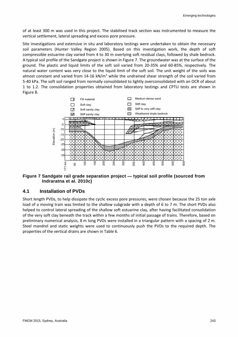
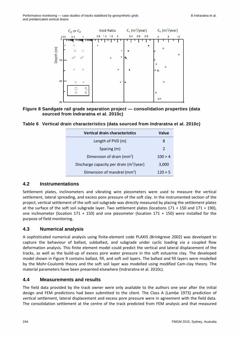
Site investigations and extensive in situ and laboratory testings were undertaken to obtain the necessary soil parameters (Hunter Valley Region 2005). Based on this investigation work, the depth of soft compressible estuarine clay varied from 4 to 30 m overlying soft residual clays, followed by shale bedrock. A typical soil profile of the Sandgate project is shown in Figure 7. The groundwater was at the surface of the ground. The plastic and liquid limits of the soft soil varied from 20-35% and 60-85%, respectively. The natural water content was very close to the liquid limit of the soft soil. The unit weight of the soils was almost constant and varied from 14-16 kN/m3 while the undrained shear strength of the soil varied from 5-40 kPa. The soft soil ranged from normally consolidated to lightly overconsolidated with an OCR of about 1 to 1.2. The consolidation properties obtained from laboratory testings and CPTU tests are shown in Figure 8.
Figure 7 Sandgate rail grade separation project — typical soil profile (sourced from Indraratna et al. 2010c)
4.1 Installation of PVDs
Short length PVDs, to help dissipate the cyclic excess pore pressures, were chosen because the 25 ton axle load of a moving train was limited to the shallow subgrade with a depth of 6 to 7 m. The short PVDs also helped to control lateral spreading of the shallow soft estuarine clay, after having facilitated consolidation of the very soft clay beneath the track within a few months of initial passage of trains. Therefore, based on preliminary numerical analysis, 8 m long PVDs were installed in a triangular pattern with a spacing of 2 m. Steel mandrel and static weights were used to continuously push the PVDs to the required depth. The properties of the vertical drains are shown in Table 6.
Performance monitoring — case studies of tracks stabilised by geosynthetic grids B Indraratna et al. and prefabricated vertical drains
244 FMGM 2015, Sydney, Australia
Figure 8 Sandgate rail grade separation project — consolidation properties (data sourced from Indraratna et al. 2010c)
Table 6 Vertical drain characteristics (data sourced from Indraratna et al. 2010c)
Vertical drain characteristics Value
Length of PVD (m) 8
Spacing (m) 2
Dimension of drain (mm2) 100 × 4
Discharge capacity per drain (m3/year) 3,000
Dimension of mandrel (mm2) 120 × 5
4.2 Instrumentations
Settlement plates, inclinometers and vibrating wire piezometers were used to measure the vertical settlement, lateral spreading, and excess pore pressure of the soft clay. In the instrumented section of the project, vertical settlement of the soft soil subgrade was directly measured by placing the settlement plates at the surface of the soft soil subgrade layer. Two settlement plates (locations 171 + 150 and 171 + 190), one inclinometer (location 171 + 150) and one piezometer (location 171 + 150) were installed for the purpose of field monitoring.
4.3 Numerical analysis
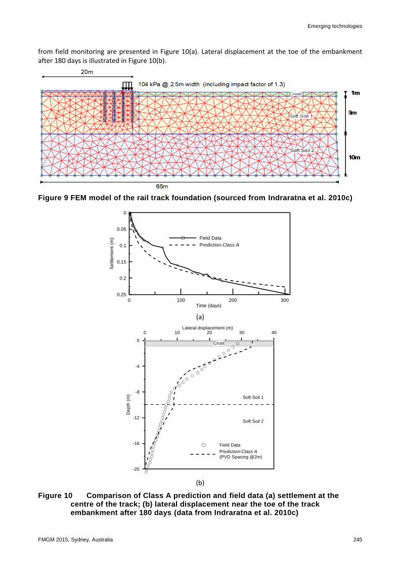
A sophisticated numerical analysis using finite-element code PLAXIS (Brinkgreve 2002) was developed to capture the behaviour of ballast, subballast, and subgrade under cyclic loading via a coupled flow deformation analysis. This finite element model could predict the vertical and lateral displacement of the tracks, as well as the build-up of excess pore water pressure in the soft estuarine clay. The developed model shown in Figure 9 contains ballast, fill, and soft soil layers. The ballast and fill layers were modelled by the Mohr-Coulomb theory and the soft soil layer was modelled using modified Cam-clay theory. The material parameters have been presented elsewhere (Indraratna et al. 2010c).
4.4 Measurements and results
The field data provided by the track owner were only available to the authors one year after the initial design and FEM predictions had been submitted to the client. The Class A (Lambe 1973) prediction of vertical settlement, lateral displacement and excess pore pressure were in agreement with the field data. The consolidation settlement at the centre of the track predicted from FEM analysis and that measured
Emerging technologies
FMGM 2015, Sydney, Australia 245
from field monitoring are presented in Figure 10(a). Lateral displacement at the toe of the embankment after 180 days is illustrated in Figure 10(b).
Figure 9 FEM model of the rail track foundation (sourced from Indraratna et al. 2010c)
0 100 200 300Time (days)
0.25
0.2
0.15
0.1
0.05
0
Se
ttle
me
nt
(m) Field Data
Prediction-Class A
(a)
0 10 20 30 40Lateral displacement (m)
-20
-16
-12
-8
-4
0
De
pth
(m
)
Field Data
Prediction-Class A
(PVD Spacing @2m)
Crust
Soft Soil 1
Soft Soil 2
(b)
Figure 10 Comparison of Class A prediction and field data (a) settlement at the centre of the track; (b) lateral displacement near the toe of the track embankment after 180 days (data from Indraratna et al. 2010c)

Performance monitoring — case studies of tracks stabilised by geosynthetic grids B Indraratna et al. and prefabricated vertical drains
246 FMGM 2015, Sydney, Australia
5 Conclusion
The three case studies at Bulli, Singleton, and Sandgate, NSW, Australia, have increased our understanding of the geotechnical behaviour of various geosynthetics used to improve the stability of ballast and underlying subgrade for rail tracks. A comprehensive field instrumentation and monitoring program undertaken on rail tracks at these places indicated that reinforcing elements such as geogrid and geocomposite, and soil stabilisation elements such as PVDs proved to be a feasible and effective alternative to improve the performance of ballasted tracks. The geocomposite used at the Bulli track indicated that the vertical and lateral deformations of recycled and fresh ballast had reduced significantly due to the additional confinement and interlocking provided by the apertures of the geocomposite layer placed at the bottom of the ballast layer. This geocomposite reinforcement reduced the vertical deformation of fresh ballast by 33% and recycled ballast by 9%, while the reductions in lateral deformation were 49 and 11%, respectively. Recycled ballast reinforced with geocomposite performed as well as fresh ballast without any reinforcement, which indicated the potential reuse of large volumes of used ballast with geocomposite, and a subsequent reduction in the need to quarry new ballast.
The results of the Singleton study show that geogrids and geocomposite can decrease the vertical strains of the ballast, as well as reducing the rate of deterioration of ballast and decreasing the cost of its maintenance. This case study revealed that the vertical deformation of ballast could be reduced by as much as 35% and that of transient deformation by about 15%, when a geosynthetic layer is located below the ballast layer. This geosynthetic reinforcement was more beneficial for softer subgrade conditions than for stiffer subgrade, even though the traffic induced cyclic vertical stress at the sleeper-ballast and ballast-capping interfaces was higher on the stiffer subgrade. It was also evident from this field study that biaxial geogrid with a 40 × 40 aperture performed better, in terms of ballast deformation, than the other geogrids used with larger grid apertures.
The relatively short PVDs used in the Sandgate project showed that these geosynthetic drains significantly decreased the build-up of excess pore water pressure and curtailed lateral deformation during cyclic loading from moving trains. The observed continuous dissipation of excess pore pressure during the rest period further improved the stability of the track. The finite element analysis performed prior to constructing the track (Class A prediction) predicted the behaviour of the rail track and its improvement with PVDs very well. Finally, the findings of these three case studies allows for a better assessment of the ability of geosynthetic reinforcement (geocomposite and geosynthetic drains) to mitigate track degradation caused by moving trains, as well as for more economical and effective ways of maintaining ballasted rail tracks.
Acknowledgement
The Authors wish to thank the CRC for Rail innovation, Australia for its continuing support. They also express their sincere thanks to Australian Research Council (ARC) Centre of Excellence in Geotechnical Science and Engineering, Sydney Trains (formerly, RailCorp), Australian Rail Track Corporation (ARTC), Aurizon ltd. (previously Queensland Rail National), ARUP and John Holland Pty Ltd. for their keen collaboration in various research studies. The Authors also appreciated the in-kind contributions made by Geotechnical Systems Australia Pty Ltd. for providing various instruments and Polyfabrics Australia Pty Ltd for supplying the geosynthetic materials used in Bulli. The authors would also like to thank Alan Grant, Cameron Neilson and Ian Bridge of the University of Wollongong for their technical assistance throughout this study.
References
ARTC 2006a, RCP-01: Standard for Earthworks Construction Procedures, Australian Rail Track Corporation, Newcastle, Australia. ARTC 2006b, TDS-12: Standard for Formation Capping Material, Australian Rail Track Corporation, Newcastle, Australia. ARTC 2007a, ETA-04–01: Ballast Specifications, Australian Rail Track Corporation, Newcastle, Australia. ARTC 2007b, TDS-08: General Standards for Formation and Earthworks, Australian Rail Track Corporation, Newcastle, Australia. Brinkgreve, RBJ 2002, PLAXIS (version 8) User’s Manual, Delft University of Technology and PLAXIS B.V., Netherlands.

Emerging technologies
FMGM 2015, Sydney, Australia 247
Brown, SF, Kwan, J & Thom, NH 2007, 'Identifying the key parameters that influence geogrid reinforcement of railway ballast', Geotextiles and Geomembranes, vol. 25, no. 6, pp. 326-335.
Hansbo, S 1981, 'Consolidation of fine-grained soils by prefabricated drains', Proceedings of 10th International Conference on Soil Mechanics and Foundation Engineering, Stockholm, vol. 3, pp. 677-682.
Holtz, R 1987, 'Preloading with prefabricated vertical strip drains', Geotextiles and Geomembranes, vol. 6, no. 1, pp. 109-131. Hunter Valley Region 2005, Geotechnical information report for the Sandgate Rail Grade Separation, prepared by K Chan, Report
no. 21/12890//AV572. Indraratna, B & Nimbalkar, S 2013, 'Stress-strain degradation response of railway ballast stabilized with geosynthetics', Journal of
Geotechnical and Geoenvironmental Engineering, vol. 139, no. 5, pp. 684-700. Indraratna, B & Salim, W 2003, 'Deformation and degradation mechanics of recycled ballast stabilised with geosynthetics', Soils and
foundations, vol. 43, no. 4, pp. 35-46. Indraratna, B, Balasubramaniam, A & Ratnayake, P 1994, 'Performance of embankment stabilized with vertical drains on soft clay',
Journal of Geotechnical Engineering, vol. 120, no. 2, pp. 257-273. Indraratna, B, Karimullah Hussaini, SK & Vinod, J 2012, 'On the shear behavior of ballast-geosynthetic interfaces', ASTM
geotechnical testing journal, vol. 35, no. 2, pp. 305-312. Indraratna, B, Navaratnarajah, SK, Nimbalkar, S & Rujikiatkamjorn, C 2014a, 'Use of shock mats for enhanced stability of railroad
track foundation', Australian Geomechanics Journal, Special Edition: ARC Centre of Excellence for Geotechnical Science and Engineering, vol. 49, no. 4, pp. 101-111.
Indraratna, B, Nimbalkar, S & Neville, T 2013, 'Performance assessment of reinforced ballasted rail track', Proceedings of the ICE-Ground Improvement, vol. 167, no. 1, pp. 24-34.
Indraratna, B, Nimbalkar, S & Rujikiatkamjorn, C 2014b, 'From theory to practice in track geomechanics – Australian perspective for synthetic inclusions', Transportation Geotechnics, vol. 1, no. 4, pp. 171-187.
Indraratna, B, Nimbalkar, S & Rujikiatkamjorn, C 2014c, 'Enhancement of rail track performance through utilisation of geosynthetic inclusions', Geotechnical Engineering Journal of the SEAGS & AGSSEA, vol. 45, no. 1, pp. 17-27.
Indraratna, B, Nimbalkar, S & Tennakoon, NC 2010b, 'The behaviour of ballasted track foundations: track drainage and geosynthetic reinforcement', in DO Fratta, AJ Puppala & B Muhunthan (eds), Proceedings of the ASCE Annual GI Conference (GeoFlorida 2010), American Society of Civil Engineers, Reston, VA, pp. 2378-2387.
Indraratna, B, Nimbalkar, S, Christie, D, Rujikiatkamjorn, C & Vinod, J 2010a, 'Field assessment of the performance of a ballasted rail track with and without geosynthetics', Journal of Geotechnical and Geoenvironmental Engineering, vol. 136, no. 7, pp. 907-917.
Indraratna, B, Rujikiatkamjorn, C, Ewers, B & Adams, M 2010c, 'Class A prediction of the behavior of soft estuarine soil foundation stabilized by short vertical drains beneath a rail track', Journal of Geotechnical and Geoenvironmental Engineering, vol. 136, no. 5, pp. 686-696.
Indraratna, B, Salim, W & Rujikiatkamjorn, C 2011, Advanced rail geotechnology: ballasted track, CRC Press, Boca Raton, FL. Indraratna, B, Shahin, MA & Salim, W 2007, 'Stabilisation of granular media and formation soil using geosynthetics with special
reference to railway engineering', Journal of Ground Improvement, vol. 11, pp. 27-43. Jeffs, T & Marich, S 1987, 'Ballast characteristics in the laboratory', Proceedings of the 4th Conference on Railway Engineering,
Institute of Engineers, Barton, Australia, pp. 141-147. Johnson, SJ 1970, 'Precompression for improving foundation soils', Journal of the Soil Mechanics and Foundations Division, vol. 96,
no. 1, pp. 111-114. Lackenby, J, Indraratna, B, McDowell, G & Christie, D 2007, 'Effect of confining pressure on ballast degradation and deformation
under cyclic triaxial loading', Geotechnique, vol. 57, pp. 527-536. Lambe, T 1973, 'Predictions in soil engineering', Geotechnique, vol. 23, no. 2, pp. 151-202. Li, AL & Rowe, RK 2001, 'Combined effects of reinforcement and prefabricated vertical drains on embankment performance',
Canadian Geotechnical Journal, vol. 38, no. 6, pp. 1266-1282. Newcastle Geotech 2011, Geotechnical investigation of specific areas of track formation concern for Minimbah Bank Stage 1 Third
Track, prepared by M Delaney, NSW, Australia, Report no. 138-4. Nimbalkar, S, Indraratna, B, Dash, S & Christie, D 2012, 'Improved performance of railway ballast under impact loads using shock
mats', Journal of Geotechnical and Geoenvironmental Engineering, vol. 138, no. 3, pp. 281-294. Raymond, GP 2002, 'Reinforced ballast behaviour subjected to repeated load', Geotextiles and Geomembranes, vol. 20, no. 1,
pp. 39-61. Robertson, PK 1990, 'Soil classification using the cone penetration test', Canadian Geotechnical Journal, vol. 27, no. 1, pp. 151-158. Selig, ET & Waters, JM 1994, Track geotechnology and substructure management, Thomas Telford, London.