performance evaluation of a biogas stove
TRANSCRIPT

© 2019 Discovery Publication. All Rights Reserved. www.discoveryjournals.org OPEN ACCESS
Pag
e58
ARTICLE REPORT
Performance evaluation of a biogas stove
Muhammadu Masin Muhammadu1, Bongdap Nanbol Keza2
1Department of Mechanical Engineering, Federal University of Technology P.M.B.65, Minna, Nigeria, E-mail:
2Department of Mechanical Engineering, Federal University of Technology P.M.B.65, Minna, Nigeria, E-mail:
Corresponding author:
Department of Mechanical Engineering, Federal University of Technology, P.M.B.65, Minna, Nigeria.
E-mail: [email protected], Mobile phone: (+234)08032551954
Article History
Received: 08 April 2019
Accepted: 13 May 2019
Published: May 2019
Citation
Muhammadu Masin Muhammadu, Bongdap Nanbol Keza. Performance evaluation of a biogas stove. Science & Technology, 2019, 5,
58-68
Publication License
This work is licensed under a Creative Commons Attribution 4.0 International License.
General Note
Article is recommended to print as color digital version in recycled paper.
ABSTRACT
This paper dwells on the design, fabrication and testing of a biogas stove from the locally available materials and fed with easily
available cow dung as a seeder and kitchen wastes as continuous feed stock which yields much gas within 24 hours of charge
resulting in a burning biogas stove for household usage. The methane gas from anaerobic digestion of kitchen waste was obtained
and the effect of temperature and temperature change on the activities of the mesophilic and thermophilic bacteria on the slurry in
the digester was also determined. It was found out that the observation and experimental test that the rate of gas produced and
retention time was greatly dependent on the ambient temperature of the surrounding environment.
Keywords: feedstock, Cow dung, feeder, methane, temperature
REPORT VOL. 5, 2019
ISSN 2394–3750
EISSN
2394–3769
SCIENCE TECHNOLOGY
&

© 2019 Discovery Publication. All Rights Reserved. www.discoveryjournals.org OPEN ACCESS
Pag
e59
ARTICLE REPORT
Abbreviations: CH4- Methane, CO2- Carbon dioxide, CO- Carbon monoxide, D- diameter, g- gram, H2- hydrogen, h1- height of the
digester, Hs- height of the slurry, H2S- Hydrogen sulphide, kw- kilowatt, M- metre, m3- volume, N2- nitrogen, NM- newton/metre,
O2- oxygen, o- degree, oc- degree centigrade, p- pressure, Ps- pressure of the slurry, Pg- pressure of the gas, PT - total pressure, rpm-
revolution per minute, r- radius, t- wall thickness, Vc- volume of the gas collecting cone, Vf- volume of the fermentation, Vgs- volume
of the gas storage chamber, Vgc- volume of the gas collector, VL- loading volume, %- percentage, 𝜌s - density slurry, and𝜎- hoop
stress.
1. INTRODUCTION
The persistent increase in World population resulting in high energy demand posed researches for alternative energy sources, as the
present fossil fuel reserves are depleting. It was estimated that if the World population continues to grow at the rate of 15% and if
all people in the World were to enjoy a standard of living and energy consumption rate similar to that of the average America, then
the World’s fossil fuel reserves would last only about 15 years (Alaxander in 1961).
To address this anticipated energy crisis, biogas is an alternative energy source among many other options, especially in Nigeria
where large quantities of animal wastes is produced annually. The biological gasification of biomass materials is one of the
affordable methods of proving energy for in situ application on Nigeria farms and villages for example, garri-frying and bread
baking. The use of methane gas plants as a source of fuel and fertilizer is a practice only recently introduced in this century. The
process of bacterial decomposition has occurred in nature since life begins plants and animals die and are recycled to sustain life on
the planet. In the presence of oxygen, organic material “composts” (undergoes, aerobic decomposition). When decomposition
occurs in the absence of oxygen (anaerobic conditions) methane gas is produced, and the liquid remainder is rich in nitrogen and
other nutrients. The term ‘biogas’ is now used throughout the World rather than “methane gas” to describe the fuel produced
through anaerobic fermentation of manures and vegetable matter in digesters. Biogas is generally between 50 and 70 percent
methane, with the remainder consisting of carbon dioxide, hydrogen sulphide and other trace gases (BNRW in 1996).
The high availability of cattle in Northern Nigeria presents a cheap source of raw material for this alternative energy source, this
will go a long way to solve energy crisis in Nigeria. Therefore the abattoirs will be good site plants or source centres for this
technology.
Biogas originated from bacteria during the process of biodegradation of organic materials under anaerobic conditions. This is
the mixture of gas produced by methanogenic bacteria while acting upon biodegradable materials in an anaerobic condition. Biogas
is mainly composed of 50 to 70 percent methane (CH2), 30 to 40 percent carbon dioxide (CO2) and low amount of other gases.
Biogas is about 20 percent lighter than air. It is an odourless and colourless gas that burns with clear blue flame similar to that of
LPG gas. Its calorific value is 20mj/m3 and burns with 60% efficiency in a convectional biogas stove. Biodigester are a physical
structure, commonly known as the biogas plant. Since various chemical and microbiological reactions take place in the biodigester,
it is also known as bioreactor or anaerobic reactor. The main function of this structure is to provide anaerobic condition within it.
There are anaerobic bacteria that act in the digester. Methanogenic bacteria or methanogens are the bacteria that act upon organic
materials and produce methane and other gasses in the process of completing their life cycle in an anaerobic condition. As living
organism they tend to prefer certain conditions and are sensitive to micro-climate within the digester.
The terminal stage of anaerobic digestion is the biological process of methanogensis. Here methanogens utilise the intermediate
products of the preceding stages and converts them into methane. Carbon dioxide and water - It is this component that makes up
the majority of the biogas emitted from the system. Methanogenesis is sensitive to both high and low pHs and occurs between pH
6.5 and pH 8. The remaining non digestible material which the microbes cannot feed upon along with any dead bacterial remains
constitutes the digestive.
A simplified chemical equation for the overall process is a follows:
C6H12O6 3CO2 + 3CH6(1)
Feedstock is the most important initial issue when considering the application of anaerobic digestion systems to the process.
Digesters typically can accept any biodegradable material. However, if biogas production is the aim, the level of putrescibility is the
key factor in its successful application. The more putrescible the material the higher the gas yields possible from the system.

© 2019 Discovery Publication. All Rights Reserved. www.discoveryjournals.org OPEN ACCESS
Pag
e60
ARTICLE REPORT
Substrate composition is a major factor in determining the methane yield and methane production rate from the digestion of
biomass. Techniques are available to determine the compositional characteristics of the feed stock. Whilst, parameters such as
solids, elemental and organic analyses are important for digester design and operation.
There are three main types of simple biogas plants which includes: Ballon plant, fixed dome plant and floating drum plant
respectively. The ballon plant consists of a digester bag in the upper part in which the gas is stored. The inlet and outlet are attached
directly to the plastic skin of the ballon. Fixed Dome Chinese model biogas plant (also called drum less digester) was built in China
as early as 1939. It consists of an underground brick masonry compartment (fermentation chamber) with a dome on the top for gas
storage. However, floating Drum plant, experiments on biogas technology in India began in 1973. This consists of an underground
digester and a moving gas holder. The gasholder floats either directly on the fermentation slurry or in a water jacket of its own. The
gas is collected in the gas drum, which rises or moves down, according to the amount of gas stored (Cruazon et al. 2007).
Table 2 Temperature variation
NOON (12. 00) EVENING (5:00 PM)
HRT
(days)
Ambient
Temperature
(℃)
Digester
Temperature
(℃ )
Ambient
Temperature
( )
Digester
Temperature
( )
1 32 32 33 36
2 31 35 30 33
3 30 34 32 36
4 32 36 34 34
5 38 38 36 38
6 32 34 33 35
7 34 36 34 37
8 34 39 35 38
9 30 36 34 37
10 32 35 33 36
11 34 38 32 36
12 32 40 33 40
13 28 32 30 38
14 29 38 30 40
15 32 37 32 38
16 30 37 30 38
17 32 40 35 42
18 26 32 24 37
19 32 41 34 42
20 32 37 33 40
21 32 42 32 40
(Source: Muhammadu et al, 2011)
© 2019 Discovery Publication. All Rights Reserved. www.discoveryjournals.org OPEN ACCESS
Pag
e61
ARTICLE REPORT
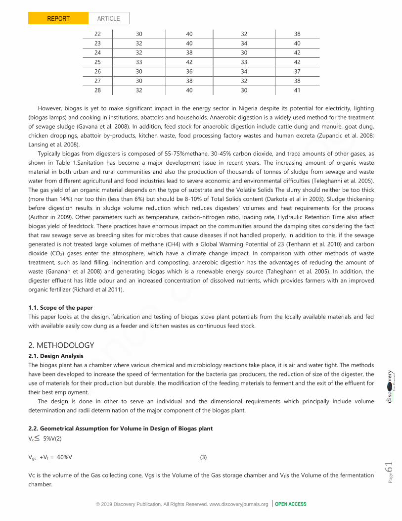
22 30 40 32 38
23 32 40 34 40
24 32 38 30 42
25 33 42 33 42
26 30 36 34 37
27 30 38 32 38
28 32 40 30 41
However, biogas is yet to make significant impact in the energy sector in Nigeria despite its potential for electricity, lighting
(biogas lamps) and cooking in institutions, abattoirs and households. Anaerobic digestion is a widely used method for the treatment
of sewage sludge (Gavana et al. 2008). In addition, feed stock for anaerobic digestion include cattle dung and manure, goat dung,
chicken droppings, abattoir by-products, kitchen waste, food processing factory wastes and human excreta (Zupancic et al. 2008;
Lansing et al. 2008).
Typically biogas from digesters is composed of 55-75%methane, 30-45% carbon dioxide, and trace amounts of other gases, as
shown in Table 1.Sanitation has become a major development issue in recent years. The increasing amount of organic waste
material in both urban and rural communities and also the production of thousands of tonnes of sludge from sewage and waste
water from different agricultural and food industries lead to severe economic and environmental difficulties (Teleghanni et al. 2005).
The gas yield of an organic material depends on the type of substrate and the Volatile Solids The slurry should neither be too thick
(more than 14%) nor too thin (less than 6%) but should be 8-10% of Total Solids content (Darkota et al in 2003). Sludge thickening
before digestion results in sludge volume reduction which reduces digesters’ volumes and heat requirements for the process
(Author in 2009). Other parameters such as temperature, carbon-nitrogen ratio, loading rate, Hydraulic Retention Time also affect
biogas yield of feedstock. These practices have enormous impact on the communities around the damping sites considering the fact
that raw sewage serve as breeding sites for microbes that cause diseases if not handled properly. In addition to this, if the sewage
generated is not treated large volumes of methane (CH4) with a Global Warming Potential of 23 (Tenhann et al. 2010) and carbon
dioxide (CO2) gases enter the atmosphere, which have a climate change impact. In comparison with other methods of waste
treatment, such as land filling, incineration and composting, anaerobic digestion has the advantages of reducing the amount of
waste (Gananah et al 2008) and generating biogas which is a renewable energy source (Taheghann et al. 2005). In addition, the
digester effluent has little odour and an increased concentration of dissolved nutrients, which provides farmers with an improved
organic fertilizer (Richard et al 2011).
1.1. Scope of the paper
This paper looks at the design, fabrication and testing of biogas stove plant potentials from the locally available materials and fed
with available easily cow dung as a feeder and kitchen wastes as continuous feed stock.
2. METHODOLOGY
2.1. Design Analysis
The biogas plant has a chamber where various chemical and microbiology reactions take place, it is air and water tight. The methods
have been developed to increase the speed of fermentation for the bacteria gas producers, the reduction of size of the digester, the
use of materials for their production but durable, the modification of the feeding materials to ferment and the exit of the effluent for
their best employment.
The design is done in other to serve an individual and the dimensional requirements which principally include volume
determination and radii determination of the major component of the biogas plant.
2.2. Geometrical Assumption for Volume in Design of Biogas plant
Vc 5%V(2)
Vgs +Vf = 60%V (3)
Vc is the volume of the Gas collecting cone, Vgs is the Volume of the Gas storage chamber and Vfis the Volume of the fermentation
chamber.

© 2019 Discovery Publication. All Rights Reserved. www.discoveryjournals.org OPEN ACCESS
Pag
e62
ARTICLE REPORT
So that the total Volume, V of the Digester = V = Vgs +Vf (4)
In geometrical Dimension Assumption for the Biogas plant
1.1477 V1/3 (5)
2.3. Volume Calculation for the Required Slurry Digester
The amount of slurry required for the workability of the digester determines the actual size and volume of the digester itself. It is
approximated that an individual needs 0.6m3 daily for cooking.
In a kitchen waste biogas system, a 1.5kg feedstock of kitchen waste produces about 500grammes, approximately 0.525m3 of
methane and the reaction is completed in 48 hours.
Since 1.5kg of kitchen waste produces 0.525m3, then 1kg will produce 0.525 ×1
1.5= 0.35m3
The required mass of kitchen waste per day is 0.6
0.36= 1.7143kg 2kg
This implies that the plant can be invariably fed with 2kg on the maximum each day.
Since the standard slurry (water-mature) mixture ratio is 1:1
Taking the HRT to be 21 days (Kitchen waste Biogas, www.corperwiki.com, September, 2011)
Total mass of input for 30 days is 4kg slurry/ day 30 =120kg (6)
Since 1000kg requires a digester of 1m3
144kg will require a digester of 144
1000= 0.12m3 (7)
Therefore 0.144m3 is the working volume of the digester, Vf
This implies that,the maximum capacity of the fermentation well is approximately 0.244m3
Also in thedetermination of Diameter for the Digester Chamber, we have Working volume of digester is given by
Vf = 0.144m3
From Geometrical assumptions for design of biogas plant,
D = 1.1447 Vf1/3 , substituting,
D = 1.447 (0.144)1/3, = 0.5692m 0.6 (8)
𝜏= 0.28m 0.3
Note : Diameter of the digester approximately equals the diameter of the gas collector.

© 2019 Discovery Publication. All Rights Reserved. www.discoveryjournals.org OPEN ACCESS
Pag
e63
ARTICLE REPORT
2.4. Determination of Height for the Digester Chamber
From geometrical assumptions for the design of biogas plant, considering that the geometry of the digester is that of a cylinder,
then,
Vf =𝜋𝑟21h1 (9)
werer1 and h1 are the radius and height of the digester consecutively
Vf = 3.142 (0.28)2 h2, (10)
Figure 1
All dimensions are in mm
Figure 2
Anaerobic digestion steps resulting in the production of biogas

© 2019 Discovery Publication. All Rights Reserved. www.discoveryjournals.org OPEN ACCESS
Pag
e64
ARTICLE REPORT
But, Vf = 0.144m3
0.144 = 0.246 h1
h1 = 0.5845m 0.6m
therefore, the working height of the digester is 0.6m while the working radius is 0.3m
Todetermination of Volume for the Gas Storage Chamber, we have the gas storage drum is made to hold between 60 and 70
percent of the volume of the total daily gas production.
V gs= 60% total dailygas requiredVgs = 0.6 (0.6) = 0.36m3 (11)
2.5. Determination of Parameters for the Gas Collector Dome
Volume of cone, Vc =ℎ3
3× 𝜋𝑟2
3 (12)
taking h3= 0.3m and r3 = 0.3m
Volume of cone Vc =0.3
3× 𝜋(0.3)2 (13)
Vc= 0.04m3
2.6. Determination of the Parameters for the Gas Collector cylinder
Since the volume of the gas collector Vgs is the sum of the volumes of the cone-shaped dome and the cylinder,
Mathematically, Vgs = Vgc + Vc (14)
Where Vgc= volumeof the gas collectorcylinder
Hence, Vgc =Vgz - Vc
Vgc = 0.36 - 0.04 = 0.32m3
The radius r2 =r3 = 0.37m
Therefore, h2 =Vgc / 𝜋𝑟22 (15)
h2 = 0.32 × 7 / 22 (0.37)2
= 0.7m
Determination of the Total Volume for the Digester is Total volume of the digester is given by,
V =Vgz + Vf (16)
Where, Vc + Vgc = Vgs (17)
So, V = Vgs + Vf
V = (0.36 + 0.144)m3
V = 0.504m3

© 2019 Discovery Publication. All Rights Reserved. www.discoveryjournals.org OPEN ACCESS
Pag
e65
ARTICLE REPORT
2.7. Determination of Pressure and Stresses acting on the Plant’s Wall
The pressure acting on the digester wall is a combination of the slurry and gas pressure. The principal stresses acting are the
longitudinal stresses and the hoop stresses.
To determine the pressure acting, we use:
Ps =𝜌sgHs (18)
Where, Ps = Pressure of slurry, Nm-2, 𝜌s = Density of slurry, kgm-3Hs = Height of slurry, m, and g = 9.8ms-2
The height of the slurry is given as: Hs = 4VL / 𝜋22 (19)
Where , VL = loading volume of slurry = Vf = 0.06m3 daily charge
dL = diameter of digester tank, m𝜋 = 3.142
therefore,Hs = 4 0.06 / 𝜋 × 0.42 = 0.5
𝜌s = 1081kgm-3 (density of slurry)
Ps = 1081 9.8 0.5 = 5296.9 NM-2
The pressure of the gas acting on the wall of the digester is given as:
Pg =PgVL/ Vgc
Where, Pg = Pressure of gas, NM-2 VL= Loading volume of slurry, m3
Vgc = Gas collection volume, m3
Therefore, Pg= 5296.9 0.06 / 0.32 = 993.2 NM-2
Total pressure acting on the wall of tank is given as:
PT = 5296.9 + 993.2 = 6290 NM-2
2.8. Determination of the Principal Hoop and Longitudinal Stresses in the Shell
Consider the equilibrium of a half cylinder of length h, sectional through a diametric plane. The hoop stress 𝜎1 acting is given by:
𝜎1 = PTd1/ 2t (20)
Where 𝜎1 = hoop stress, NM-2 , PT = total pressure, NM-2, t = wall thickness, m = 0.0005m and d1 =diameter of digester tank, m
𝜎1 = 6290 0.4 / 2 0.0005 = 2516027.5NM-2
Also, considering an equilibrium section out by a transverse plane
The longitudinal stress 𝜎2 is given as:
𝜎2 = PTd1 / 4t, (21)
substituting the values, we have
= 6290 0.4 / 4 0.0005 = 1258013.8 NM-2
2.9. Facts about Biogas from high caloric feedstock
Using high caloric feedstock such as starchy or sugary feedstock (waste grain flour, spoilt grain, overripe or misshapen fruit, non-
edible seeds, fruits and rhizomes, green leaves kitchen waste, leftover food) has boosted methane production because the caloric
value has not been reduced by the activity of the animals like in the case of the cow dung.

© 2019 Discovery Publication. All Rights Reserved. www.discoveryjournals.org OPEN ACCESS
Pag
e66
ARTICLE REPORT
Graph 2
Shows relation between the o2 emission and generation efficiency for bio gas
Graph 3
Shows noon result
Graph 4
Shows evening result
Graph 1
Temperature variation on day 1

© 2019 Discovery Publication. All Rights Reserved. www.discoveryjournals.org OPEN ACCESS
Pag
e67
ARTICLE REPORT
In this case, 2kg of such feedstock produces about 500g (0.7m3) of methane and the reaction is completed within 24 hours.
Conversely, the conventional feeding type utilizing cow dung uses about 14kg feedstock to produce the same 500g of methane,
requiring about 40days completing the reaction. Biogas may be improved by filtering it through limewater to remove carbon
dioxide, iron fillings absorb corrosive hydrogen sulphide and calcium chloride to extract water vapour after the other two processes.
3. DISCUSSION OF RESULTS
The purpose of the study is to obtain methane gas from anaerobic digestion of kitchen waste and also to determine the effect of
temperature and temperature change on the activities of the mesophilic and thermophilic bacteria on the slurry in the digester.
It was realized through the observation and experimental test that the rate of gas produced and retention time (with 24 hours
biogas was produced) is greatly dependent on the ambient temperature of the surrounding environments, which in turn determines
the temperature of the digester, and that fermentation of a mixture of different kitchen waste including rice, beans, lettuce, cabbage
and carrot had more gas after 24 hours than the convectional use of cow dung using the mass of ingest as platform for efficiency
and mobility of plant.
3.1. Discussion of Graph analysis
The plant was tested for a 30 days period and the various parameters expected were looked out for. The varying ambient
temperature and how it affected the reaction that occurred in the plant, its effect on the digester temperature showed that the
mesophilic bacteria had developed and as the days progressed the effect was discovered as the digester temperature increased and
later climaxed at a temperature, the initial average base temperature of the slurry was about 250 and maximum during the period of
test was about 420. At a time, there was a leakage as bubbles of water was discovered to come out as stirring was done, this showed
that gas formation had occurred and there was actually pressure being built up in the plant. The temperature was carried out in two
(2) phase: Noon (12: 00) and Evening (5:00 pm) as shown in graph 3 and graph 4 respectively. As tests continue and other materials
are tested it can be inferred that the temperature might be higher or lesser but it is still going to follow the same variance.
3.2. Principle of Operation
Biogas digesters work on the principle of anaerobic digestion – a natural, biological process similar to composting that breaks down
liquid manure, sewage, or other organic wastes. In the process, biogas is produced. This biogas is about 55 – 75% methane (the
primary component of natural gas) and therefore can make an excellent energy source.
The decomposition is done by the actions of some bacteria on the waste to be digested in the absence of air, the waste, which in
this case is a mixture of waste food from restaurant within the environment. These bacteria generally thrive at two temperature
“zones” from 95 – 105OF, and from 125 to 135oF. Although anaerobic digestion occurs at lower temperatures, it is not as efficient at
producing biogas. The gas produced is then collected and stored in the floating gas collector above the digester harnessed by a
pipe controlled through the valve and then passed through a cleansing chamber for the removal of carbon dioxide from the biogas.
The gas is then finally supplied to the burner for the purpose of cooking.
5. CONCLUSION
This paper presents the design, fabrication and production of a mobile, portable biogas plant, especially for decentralized purpose.
The design process has been carried out with other major and equally important factors. It also showcases the possibilities of having
an environmental friendly fuel that is almost priceless and very efficient. This plant is not just a paper work; it’s a solution that is the
future of renewable energy in the coming years.
The plant that has the capacity to serve an individual daily consumable fuel was successfully designed and constructed through
many phases, averagely to construction might take duration of about three weeks. The wooden plank used as a support was borne
out of the need for mobility so that it can be easily moved around to the user’s choice position.
It runs on an operating procedure that is easy, and needs little or no training neither does it need background technical
knowledge of any kind.
Future work
Due to the dynamism of the field of technology which has been experienced over the years that even the most perfect of inventions
still could be improved on, as change is the only thing that is guaranteed constancy in all ramification of life, to be able to keep up

© 2019 Discovery Publication. All Rights Reserved. www.discoveryjournals.org OPEN ACCESS
Pag
e68
ARTICLE REPORT
with the trend of things, the portable and mobile biogas plant is no exception, there are still a hundred and one improvements that
could still be carried out on it: but only a few will be highlighted below:
1. To prevent leakage which was a major setback for this design, tolerance between the digester and the as collector should be
carried out more intricately.
2. To properly monitor the events that occur in the plant a pressure gauge in N/M3 should be incorporated and not the gauge
calibrated in ‘bar’.
3. A thermocouple should be incorporated in to the digester of the plant, to monitor the temperature in the plant effectively and
accurately.
4. All inlet and outlet should be properly sealed either by a valve or a guage.
5. Various tests should be carried out to ensure the air tightness of the entire plant and
6. Other waste materials should be explored respectively.
RREEFFEERREENNCCEE
1. Alexander, M, Introduction to Soil Microbiology, John Wiley
and Sons, Inc. Pp 227- 231 (1961).
2. Biogas and Natural Resources Management (BNRM)
Newsletter, Issue No. 1 – 51, (1996).
3. Biogas Production, http://www.habmigern2003.info/biogas/
methane-digester.html, accessed on 5th May, 2011.
4. Cruazon, B., History of Anaerobic Digestion, Pp 22 – 27
(2007).
5. Lariviere, J. W.M., Microbial Ecology of Liquid Waste
Treatment, Adv. Microbial Ecology 1:215 (1977).
6. Martin, A. D., Understanding Anaerobic Digestion, Pp 1 – 4,
Presentation to the Environment Service Association, (2009).
7. The Biogas Technology in China, Chengdu Biogas Research
Institute, China (1989).
8. Yadava, L. S., The Development and use of Biogas
Technology in Rural Areas of Asia, (A Status Report 1981).
Improving Soil Fertility through Organic Recycling,
FAO/UNDP Regional Project RAS/75/004, Project Field
Document No. 10 (1981).
9. Gavana H.N., et al. Improving anaerobic sewage sludge
digestion by implementation of a hyper-thermophilic
prehydrolysis step. J Environ Manage 2008;88(4):881-6.
10. Zupancic GD, Uranjek-Zevart N, Ros M. Full-scale anaerobic
co-digestion of organic waste and municipal sludge.
Biomass Bioenerg 2008; 32(2):162-7.
11. Lansing S, Botero BR, Martin JF. Waste treatment and biogas
quality in small-scale agricultural digesters.
BioresourTechnol 2008; 99(13):5881-90.
12. Taleghani G, Kia AS. Technical - economical analysis of
theSaveh biogas power plant. Renew Energy 2005;30(3):441-
6
13. Devkota GP. Biogas Installation and Training. Burma: METTA
Development Foundation, Grassroots Leadership Training
(GLT); 2003.
14. Arthur, R., 2009. Feasibility study for institutional biogas
plant for KNUST sewage treatment plant. MSc. Thesis.
Kwame Nkrumah University of Science and Technology
(KNUST), Kumasi, Ghana.
15. Fenhann, J., Halsnæs, K., Pacudan, R., Olhoff, A. CDM
information and Guidebook, Lee M, ed. 2nd edition Unep
Risø Centre, Roskilde, Denmark. http://www.cd4cdm.org/
Publications /cdm% 20 guideline % 202nd% 20 edition.pdf
(access date 15.02.10).
16. Richard A., et al, Biogas generation from sewage in four
public Universities in Ghana: A solution to potential health
risk, (2011).