performance effects of the uplink asynchronism in a spread spectrum multi-carrier multiple access...
TRANSCRIPT

Performance Effects of the Uplink Asynchronisrn in a Spread Spectrum Multi-Carrier Multiple Access System*
STEFAN KAISER German Aerospace Center (DLR), Institute for Communications Technology, D-82234 Oberpfaffenhofen, Germany
TRLabslLlniversity of Alberta, 800 Park Plaza, 1061 1 - 98 Avenue,Edmonton, Alberta, Canada T5K 2P7 wak@edm. trlabs. ca
WITOLD A. KRZYMIEN
Abstract. In this paper we investigate the effects of the asynchronism of user signals in the uplink of a spread spectrum multi-camer multiple access (SS-MC-MA) system. Different propagation delays due to different distances between the mobile transmitters and their base station cause asynchronous amvals of the uplink signals in addition to multipath propagation. The proposed uplink SS-MC-MA scheme uses for synchronization only the frame structure received on the synchronous downlink and requires no additional synchronization measures. A guard interval that is smaller than the sum of the maximum time offset between the users and the maximum excess delay of the frequency selective multipath channel is used. It minimizes the loss in bandwidth efficiency by allowing residual interference. The residual interference is minimized by proper positioning of the detection interval in the receiver. It is shown that with this approach the guard interval can be reduced by about 50%. The performance of the proposed uplink scheme is compared to an uplink SS-MC-MA scheme with perfect synchronization.
1 INTRODUCTION
Future wireless mobile communication systems will have to provide a wide range of multi-media services such as speech, image, and data transmission with variable bit rates. The new services have to be available in differ- ent indoor and outdoor application environments. To meet these requirements, it is important to consider recent de- velopments in wireless communications, such as the appli- cation of multi-carrier (MC) modulation [ 1, 21 to provide an attractive alternative to the conventional multiple access schemes FDMA, TDMA, and DS-CDMA. MC modulation in the form of orthogonal frequency division multiplex- ing (OFDM) has already become a key component of the European standards for digital audio broadcasting (DAB) and terrestrial digital video broadcasting (DVB-T). Atten- tion has now focussed on the combination of OFDM with CDMA, TDMA, and FDMA. Most research activity so far has concentrated on MC-CDMA (e.g. [3, 4, 51). Since MC modulation based approaches require accurate time and frequency synchronization to avoid inter-symbol inter-
‘This work was performed during S. Kaiser’s research visit PI the Telecommunications Research Laboratories (TRLtrhs), and was funded by TRLtrbr. [he German Aerospace Center (DLR), and the Natural Sciences & Engineenng Research Council (NSERC) of Canada.
ference (ISI) and inter-channel interference (ICI), and to achieve high bandwidth efficiency, most of the MC-CDMA schemes have been developed for the synchronous down- link. It has been shown that MC-CDMA is a very promis- ing multiple access scheme for the downlink of a mobile radio system where it enables the deployment of efficient, low complexity receivers employing simple channel esti- mation [3, 4, 5, 61. However, this statement does not ap- ply to the uplink, where more complex multi-user detection techniques are necessary to counteract the multiple access interference (MAX), since in the uplink orthogonal spread- ing codes cannot be used to reduce the MAI. For the syn- chronous uplink, a promising scheme called spread spec- trum multi-carrier multiple access (SS-MC-MA) has been recently proposed [6,7] to appropriately exploit the advan- tages of MC-CDMA evident on the downlink. On a syn- chronous uplink SS-MC-MA is an interesting alternative to other MC multiple access schemes such as MC-FDMA, MC-TDMA, and MC-CDMA [6, 81, as discussed in [9 ] .
There are various possibilities to deal with the time off- sets between the user signals in the uplink. The uplink time offsets at the base station can be eliminated as in the GSM system [lo] by estimating the time delay between a mo- bile transmitter and its base station, and correcting for it.
Vol. 10. NU. 4, J ~ l y - A ~ g u ~ t 1999 399

S. Kaiser, W. A. Krzymien
However, the required synchronization scheme is complex. Another solution is to insert at each OFDM symbol a guard interval (which has to be longer than the sum of the max- imum time offset between the user signals and the maxi- mum excess delay of the mobile radio channel) containing a cyclic extension. This approach, however, can result in substantial reduction of bandwidth efficiency (especially in large cells) due to the excessive length of required guard intervals.
In this paper, we analyze the effects of user asynchro- nism in the uplink of SS-MC-MA systems. A simple up- link scheme is considered which synchronizes on the frame structure received on the synchronous downlink. In order to reduce the system complexity, no additional synchroniza- tion measures are considered for the uplink. We propose and investigate an approach which allows a certain amount of IS1 and ICI, but in return reduces the loss in bandwidth efficiency due to the guard interval. By optimally placing the receiver detection interval, the residual IS1 and ICI are minimized, and the complexity of a dedicated uplink syn- chronization scheme is avoided. The residual interference is evaluated and the resulting performance degradation is determined by comparison with a perfectly synchronized uplink.
The paper is organized as follows. In Section 2 the prin- ciple of SS-MC-MA in the uplink is described. The loss of synchronism in the uplink due to different signal propaga- tion delays is discussed in Section 3. The resulting interfer- ence is described mathematically in Section 4. In Section 5 we present a method to mitigate interference in the up- link, intentionally allowed to reduce the loss of bandwidth efficiency. Performance of the proposed scheme is com- pared to a perfectly synchronized SS-MC-MA in Section 6. Finally, Section 7 summarizes the results.
2 SS-MC-MA UPLINK STRUCTURE
The SS-MC-MA system investigated in this paper ac- commodates A‘ simultaneously active users in the uplink. It is an FDMA scheme on subcakier level, and each user k , k = 1,. . . , K , exclusively transmits on a set of L subcar- riers out of a total of N, subcarriers. The total number of subcarriers is given by
The block diagram of the mobile SS-MC-MA transmit- ter for user k is shown in Fig. 1. After channel cod- ing, code bit interleaving, and QPSK symbol mapping, L complex-valued data symbols dj”, 1 = 0, . . . , L - 1, of user k are spread by multiplication with orthogonal Walsh- Hadamard codes of size L, and superimposed with each other on L subcarriers. The L orthogonal spreading codes are c( = (c l ,o tc i ,1 , . . . , c l , ~ - l ) , 1 = 0, . . . , L - 1. There-
data source of user t
Figure I : SS-MC-MA transmitter.
sulting sequence is s(~) = (Sc), Sik), . . . Sf?,), where
Variables which can be interpreted as values in the fre- quency domain, like the elements SJk’. j = 0, . . . t L - 1, each modulating another subcarrier frequency, are written with capital letters. The elements Sjk’, j = 0, . . . , L - 1, modulate in parallel the subcarriers assigned to user k . In order to optimally exploit the frequency diversity offered by the mobile radio channel, the subcarriers assigned to dif- ferent users are interleaved so that the subcarriers used by a given user are spaced by K / T S . This subcarrier assignment is referred to as user specific frequency mapping [6, 71. To achieve MC modulatioddemodulation the OFDM opera- tion is applied. It is efficiently implemented with IF lTFFT algorithms [I]. A block of N , subcarriers modulated by one set of ~ ( ~ 1 , k = 1,. . . , I<, is referred to as an OFDM symbol of duration Ta. According to the OFDM principles, the N, substreams modulate subcarriers with a spacing of l/Ta. Possible IS1 and ICI can be mitigated by inserting a guard interval of duration Tg between successive OFDM symbols [2, 113. The guard interval is occupied by a cyclic prefix, resulting in the extended OFDM symbol of duration ‘7’: = T, + T,. pilot
The block diagram of the SS-MC-MA receiver, located at the base station, is shown in Fig. 2. After MC demodu-
Figure 2: SS-MC-MA receiver:
lation with the inverse OFDM operation and deinterleaving (i.e., user specific frequency demapping), the demodulated sequence dk) = (Rf), I?(,“), . . . I Rf?,) is obtained. Any conventional, iterative, or joint detection technique suitable for MC-CDMA can be applied for data detection. Joint de- tection for SS-MC-MA means that L data symbols of one user are jointly detected. We consider a maximum likeli- hood detector for the detection of the data of user k . After symbol demapping, code bit deinterleaving, and channel decoding, the detected source bits of user k are obtained.
400 ETT

Performance Effects of the Uplink Asynchronism in a Spread Spectrum Multi-Carrier Multiple Access System
3 ASYNCHRONISM IN THE-UPLINK
We consider the uplink of a single cell system. A low- complexity synchronization approach is used in which the users synchronize on the frame structure received on the synchronous downlink. In the uplink, significant time off- sets between the signals arriving at the base station occur due to different propagation distances between the mobile stations and the base station. The maximum time offset be- tween signals from different users within a cell arriving at the base station is
(3) 2 R
6max = - 7 C
where Rt is the radius of the cell and c is the speed of light. The factor 2 results from the summation of the propagation delays in the downlink and the uplink. The delays of the signals of the h' users due to the propagation distance to the base station are dk) E [0,6ma,], k = 1, . . . , K . With the assumption of uniform surface distribution of users within the cell, the resulting linear probability density function of the signal delays at the base station is
As expected, long delays from users at the cell boundary occur most often. Without compensation of different prop- agation delays of the signals in the uplink and an insuffi- cient guard interval, the user synchronism is lost and inter- ference results, which can significantly deteriorate the per- formance of an OFDM system. In the following sections, the resulting interference is described and evaluated.
4 INTER-SYMBOL AND INTER-CHANNEL INTERFERENCE
In this section we present a general description of IS1 and ICI in an asynchronous multi-carrier link. We assign each subchannel n its own delay Sn, n = 0 , . . . , N, - 1. The delays on subcarriers assigned to the same user are de- termined by the location of the user, and are the same. One arbitrary symbol Sn,i is transmitted per subcarrier in one OFDM symbol. The index n is the subchannel index and i is the OFDM symbol index (discrete time). The sym- bols Sn,, are equivalent to Sjk) with their dependence on discrete time explicitly shown. In the sequel, the notation Sn,; is preferred to describe the IS1 and ICI for the sake of clarity. There are N , orthogonal subcarrier frequencies f n , separated from each other by l/T,. The nth orthogonal basis function is defined as
t When the cells are not circular, R is the maximum distance between the base station and a mobile user belonging to a given cell.
and the signal transmitted on subcarrier n is given in time domain by
a?
t = - a ?
(6 ) Considering multipath propagation with Np paths, the im- pulse response of the wideband mobile radio channel asso- ciated with the nth subcarrier is given by
N--1
(7) p = O
where p n , p is the complex-valued attenuation. The delay rn,p represents the excess delay of the pth path of subchan- nel n. The transmission bandwidth, l/T,, used by the nth subchannel is small compared to the coherence bandwidth of the mobile radio channel associated with the nth subcar- rier and described by hn( t ) . Therefore, fading on the nth subchannel of bandwidth l/Ts is flat [12]. For the sake of generality, an impulse response h n ( t ) is defined for each subchannel. For simplicity it is assumed that all channel impulse responses hn(t) , n = 0, . . . , N , - 1, have the same number of paths N p . The total delay E , , ~ per arriving path p on subchannel n at the base station is the sum of the prop- agation delay 6, and path delay
(8)
where fn ,p E [O, fmax], Emax = L a x + rmax, and Tmax is the maximum excess delay of any subchannel.
The received signal y(t) is the sum of the convolutions of zn(t) with hn( t ) over all subcarriers and an additive noise term n(t) , thus,
i.e.,
En,p = 6n + rn!p,
Nc-1
(9)
where the symbol * denotes convolution. The demodula- tion of subcarrier rn in the receiver involves a simple corre- lation with @,, (t - i Ti) over the effective OFDM symbol duration T,, i.e.,
Rmli = 5;; y ( t ) 4k(t - iT:) dt 0
(10)
l i '
= Ym,i + Nrn,i.
The symbol (.)' denotes complex conjugation. The com- ponent Nm,i corresponds to the additive noise component n( t ) after demodulation. The output Ym,; of the demodula- tor is the noise-free decision variable that includes IS1 and ICI. Ym,i can be written as
Vol. 10. NO. 4. July-August 1999 40 I

S . Kaiser, W. A. Krzymien
Xm,n(En,p) = (12) if 0 5 t n , p < Tg
if cn,p 1 Ty sin (n(n - m)(t,,, - T,)/T.) a n - m )
eJ .( 2n( p ) -( n - m) (en, -Tg ) / T.
(13)
( 0 and
Pm,n(En,p) = sin( n(n - m ) )
n(n - m) sin (r(n - m)(T: - c , , , ~ ) / { . e 3 ~ ( 2 n r " , p - ( n - m ) ( T : - e ~ , p ) ) / T y
if 0 5 e n , p < Ty
Ts) if 2 T~ a(n - m )
The desired component in (11) on subcarrier m is Pm,p Sm,i p , , , , , ( ~ ~ , ~ ) and the IS1 on the same subcarrier is pm,p S m , t - l Xn,m(€m,p). ICIfrom the subcarriers R # misgivenbypn,p ( S n , i pm,n(cn,p) + s n , i - 1 x m , n ( C n , p ) ) . The average signal-to-interference power ratio (SIR) on subcarrier m is
where P, is the power of the desired component and PICI + PISI is the interference power. With the assump- tion that the average received power on all subcarriers is the same due to power control and, furthermore, that the transmitted data symbols are statistically independent, the average SIR on subcarrier m is
5 INTERFERENCE MITIGATION
Two detection concepts differing in the choice of the position of the detection interval in the receiver are inves-
tigated. The SS-MC-MA uplink scheme which minimizes the residual interference is referred to as Concept I. In the design referred to as Concept I1 each user minimizes the interference originating from its own set of subcarriers, but it does not attempt to minimize the interference from other asynchronous users. In other words, in Concept II each user optimizes its detection interval with respect to its own multipath channel.
For an SS-MC-MA mobile radio system with channel estimation as described in [6, 71, the assumption can be made that the base station has the knowledge about the ar- rival time 6 ( k ) of each user. To obtain d'(k) simply a corre- lation of the received signal with the known pilot symbol grid on the subcarriers exclusively used by a given user has to be performed. Moreover, we assume to know the max- imum excess delay rmax on the radio channels used. A given value of rmax can be assumed in the uplink design, or its actual value can be obtained from channel estimation.
The subset of subcarriers exclusively assigned in SS- MC-MA to user k is denoted as A(k) . When all subcarriers are in use, we obtain
R
k = l
where llA(k)l 1 is the number of elements in subset
5.1 CONCEPTI
In order to keep the loss in bandwidth efficiency due to the insertion of guard intervals at a tolerable level, we con- sider an uplink scheme which allows IS1 and ICI by choos- ing Tg < fmax , i.e., we use a short guard interval. At the same time the detection interval in the receiver is chosen such that the residual interference is minimized. Principle features of the Concept I are illustrated in Fig. 3. To cal- culate the SIR for Concept I according to (15) and using (12) and (13), a new time delay variable has to be defined. Signals arriving earlier compared to the detection interval have to be transformed to the case with a delayed arrival since (12) and (13) are only valid for delays E ~ , ~ 2 0, i.e., not for earlier arriving signals. The new time delay variable
is defined as
(17) En,p - n if E , , , ~ 2 A
A - entp + Tg otherwise '
where A + T, is the beginning of the integration interval for demodulation (of duration T8), which is the same for all users. The time shift A can take on values in the inter- val [0, fmax - Tg). The case 2 A in ( 17) describes the situation where the signal on subcarrier n is delayed compared to the detection interval. The operation cn,p - A shifts the zero of the time axis such that (12) and (13) can be applied. The case c , , , ~ < A in (17) is valid when the sig- nal on subcarrier n arrives earlier compared to the detection
307- ETT

Performance Effects of the Uplink Asynchronism in a Spread Spectrum Multi-Carrier Multiple Access System
Concept I
detection interval
6- Ern,, E
A +T, TS 4 D
I I
7 i userk-1 I c i user k t I
.111 1 userk+l
A t . - , \ ,"\ guard interval OFOM symbol
user k-1
user k
user k t l
Concept II
Figure 3: Principle of interference mitigation wirh Concept1 and Concept II.
interval. The operation A - inverts the earlier arrivals to delays such that (12) and (13) can be applied. The ad- ditional shift of T, is necessary since interference occurs always with earlier arrived signals and no advantage can be gained from the guard interval, i.e., only the second case in (12) and (1 3) is possible. The transformation of earlier arrivals to delays is valid since the interference power is the same due to symmetry. With Concept I and the new time delay variable (n,p the SIR is given by
I N,-1
Through (17) the SIR depends on the parameter A. To op- timally choose A, the probability density function p c ( c ) of the total delay c , , ~ , R = 0, . . . , N , - 1, p = 0, . . . , Np - 1, has to be considered. The probability density function p , ( e ) is obtained by convolution of the probability density function pa(b( ' ) ) , see (4), and the probability density func- tion p , ( T ) of the multipath propagation delay
(19) Given (4) and a p r ( r ) as an exponentially or linearly decreasing function with maximum excess delay rmnx, the probability density function ~ ~ ( 6 ) can be approx- imated by a linearly increasing function in the inter- val 0 5 6 < s,,, and linearly decreasing in the interval
~c (0 = P-J ( 6 ) * P r (€1.
smax _< 6 < Tmax + bmax, and 0 otherwise (see Fig. 3). The interference which is not absorbed by the guard in- terval is minimized by choosing A as
given the approximation of p c ( 6 ) by a triangle. Numeri- cal evaluations of A with the exact p c ( c ) showed that the approximation used in this paper resulting in the analyti- cal solution (20) is sufficiently accurate. Without multipath propagation, the integration interval for demodulation of the data of all users starts at the time instant b,,,. In that case, all interference occumng from users with delays in the interval [bmax - T,, Smax) is cancelled out. Thus, ICI is minimized due to the linearly increasing characteristic of (4).
For Concept I we can define the worst case user as the user which is next to the base station and has a delay of dk) x 0 ps. Due to the fixed detection interval starting at A+T,, the worst case user in addition to the ICI from other users suffers from the maximum possible ISI.
5.2 CONCEPT I1
Concept I1 is the straightforward solution, where the integration interval for demodulation of the data of user A. starts at the time instant b(') + Tg. The integration interval can thus be different for each user in order to minimize the interference originating from its own subset of subcarriers. Hence, this approach does not take into account the prob- ability density function pd(S( ' ) ) of the delays and, thus, of the interference from other asynchronous users. For Con- cept I1 the SIR given by (1 8) reduces to
when T, > Tmaxv since as long as Tg > Tmax, this ap- proach avoids ISI, even if 2'' < Emax. Principle features of the Concept I1 are illustrated in Fig. 3.
For Concept I1 we can define the worst case user as the user with maximum distance R to the base station and a maximum delay of d k ) = d,,,. Thus, each user with b(') < b,,, interferes with the desired user, and the guard interval gives no advantage.
Vol. 10, NO. 4, July-August 1999 403
S. Kaiser. W. A. Krzvmien
System A
6 SIMULATION RESULTS
System B
The asynchronous uplink is investigated for two differ- ent SS-MC-MA mobile radio systems. System A is de- signed for medium size cells with a radius of about 2 km, typical for future outdoor cellular mobile radio systems. System B is designed for high data rate indoor and micro- cellular outdoor applications with cell radius up to 250 m. Table 1 gives the parameters of both systems.
environment cell radius R max. delay Jmax bandwidth E num. of subcar. N ,
Table 1: Parameters of rhe SS-MC-MA systems.
outdoor indoor 2 km 250 m
13.33 ps 1.67 ps 2 MHz 20 MHz
256 2048 OFDM sym. dur. T,
user capacity A-s9, 128 net bit rate Rb
128 ps guard duration Tg 15 ps
0.01 12 to 1.4 Mbit/s
102.4 ps
1 MS 1536
0.0103 to 15.8 Mbit/s carrier frequency j C spreading code symbol mapping channel code
2 GHz Walsh-Hadamard code of length L = 8
QPS K convolutional code of rate IC! and memory 6
The cell radius R and the guard interval duration T, are varied in later figures to demonstrate the effect of cell size on performance. The channel estimation is assumed to be perfect. However, in the calculation of the net bit rate per user a 20% loss due to pilot symbols is taken into account. Both systems use a TDMA frame structure where NI. is the number of time slots per TDMA frame, explained in detail in [6,7]. The duration of one TDMA frame is about 18 ms. In System A one time slot contains 3 1 OFDM sym- bols, and N l , = 4 time slots form a TDMA frame. In System B one time slot contains 29 OFDM symbols, and one TDMA frame has N!, = 6 time slots. The difference in the number of time slots between System A and B results from different OFDM symbol times, T,, and guard times, T,, for the two systems. The user capacity of the system is
The total bit rate is the bandwidth B times 2 for QPSK and divided by 2 due to the 112 channel code rate. Moreover, the 20% loss due to pilot symbols and the loss due to the guard interval have to be taken into account. The net bit rate per user Rb is obtained by dividing the total bit rate by IiJyJ which results in 11.2 kbit/s for System A and 10.3 kbitls for System B. It is possible to assign to one user sev- eral or all transmission links, such that a net bit rate up to I .4 Mbitls for System A, and 15.8 Mbitls for system B is obtained.
The mobile radio channel models are taken from [ 131. For System A the 'Outdoor Residential -High Antenna'
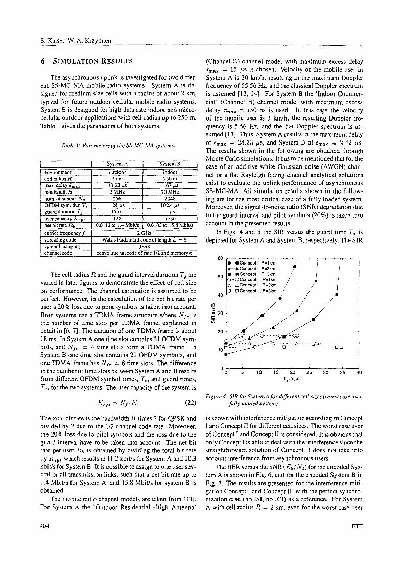
(Channel B) channel model with maximum excess delay rmaX = 15 ps is chosen. Velocity of the mobile user in System A is 30 km/h, resulting in the maximum Doppler frequency of 55.56 Hz, and the classical Doppler spectrum is assumed [13, 141. For System B the 'Indoor Commer- cial' (Channel B) channel model with maximum excess delay r,,,,, = 750 ns is used. In this case the velocity of the mobile user is 3 kmlh, the resulting Doppler fre- quency is 5.56 Hz, and the flat Doppler spectrum is as- sumed [ 131. Thus, System A results in the maximum delay of emax = 28.33 p s , and System B of E,,, = 2.42 11s. The results shown in the following are obtained through Monte Car10 simulations. It has to be mentioned that for the case of an additive white Gaussian noise (AWGN) chan- nel or a flat Rayleigh fading channel analytical solutions exist to evaluate the uplink performance of asynchronous SS-MC-MA. All simulation results shown in the follow- ing are for the most critical case-,of a fully loaded system. Moreover, the signal-to-noise ratio (SNR) degradation due to the guard interval and pilot symbols (20%) is taken into account in the presented results.
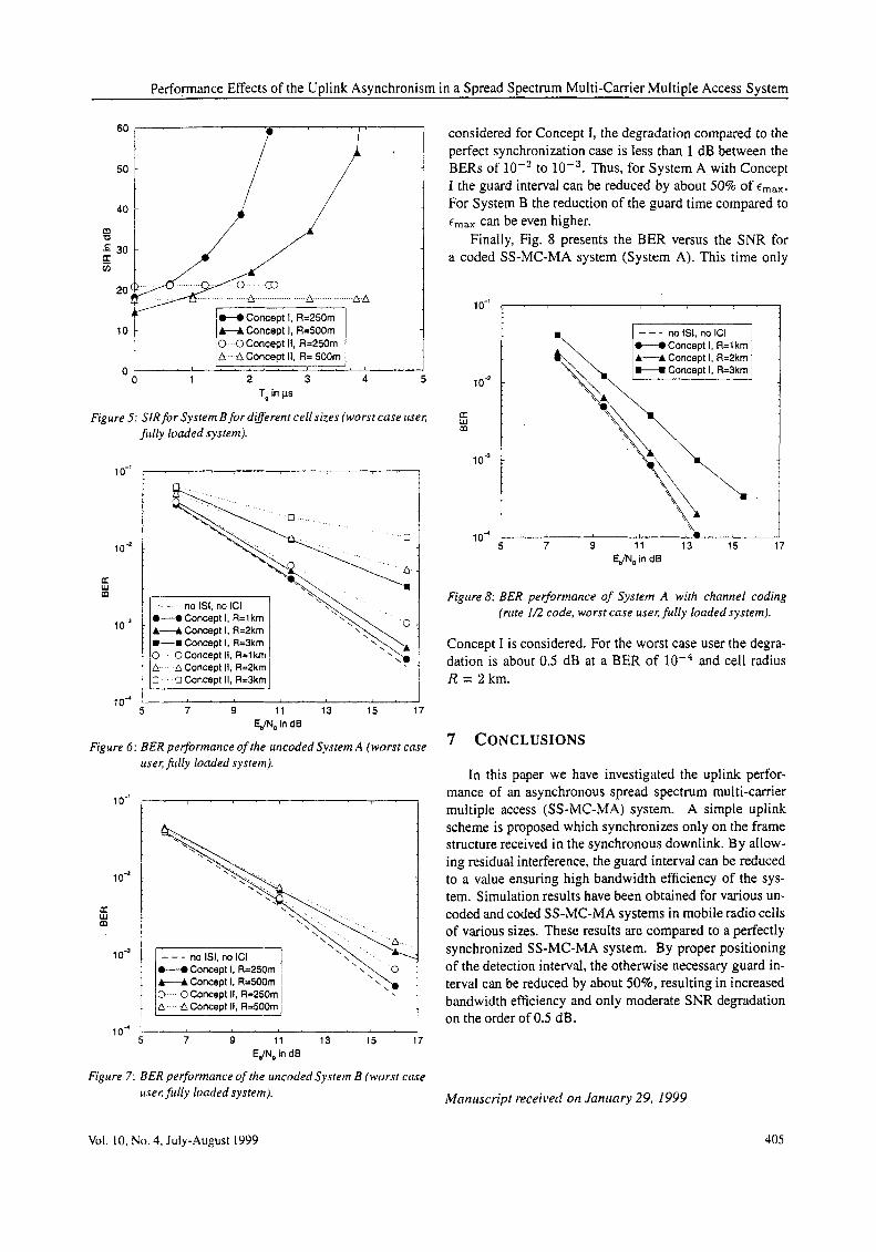
In Figs. 4 and 5 the SIR versus the guard time T, is depicted for System A and System B, respectively. The SIR
0 0 5 10 15 20 25 30 35 40
T, in ps
Figrtre 4 : SIR for Sysrem A for diflerent cell sizes {worst case Liset:
fully loaded system).
is shown with interference mitigation according to Concept I and Concept I1 for different cell sizes. The worst case user of Concept 1 and Concept I1 is considered. It is obvious that only Concept I is able to deal with the interference since the straightforward solution of Concept I1 does not take into account interference from asynchronous users.
The BER versus the SNR (Eb/;Vo) for the uncoded Sys- tem A is shown in Fig. 6, and for the uncoded System B in Fig. 7. The results are presented for the interference miti- gation Concept I and Concept 11, with the perfect synchro- nization case (no ISI, no ICI) as a reference. For System A with cell radius R = 2 km. even for the worst case user
403 ETT
Performance Effects of the Uplink Asynchronism in a Spread Spectrum Multi-Carrier Multiple Access System
20 A A
&-A Concept I, R=5OOm 0 OConcept 11, R=250m
0 1 2 3 4 5 T, in ps
0
Figure 5: SIR for System B for different cell sizes (worst case usec f i ~ l l y loaded system).
lo-'
1 o-2
U W m
1 o - ~
i
C - 0 Concept I, R=1 km A 4 Concept I, R=2km m-¤ Concept I, R=3km 0 0 Concept 11, R=1 km A A Concept II, R=2km
0 Concept II, R=Skm
7 9 11 13 15 17 lo4
EJN, in d6
Figure 6: BER pe$ormance of the uncoded System A (worst case user; fiilly loaded system).
lo-'
lo-*
U W m
1 o-'
1 oa
Figure 7 :
A--A Concept I, R=500m
6 Concept It, R=500m L I I
5 7 9 11 13 15 17 EJN, in dB
BER performance of the uncoded System B (worst cme ~iser,fiilly loaded system).
considered for Concept I, the degradation compared to the perfect synchronization case is less than 1 dB between the BERs of lo-? to lod3. Thus, for System A with Concept I the guard interval can be reduced by about 50% of cmax. For System B the reduction of the guard time compared to cmax can be even higher.
Finally, Fig. 8 presents the BER versus the SNR for a coded SS-MC-MA system (System A). This time only
lo-'
lo-*
U W m
1 o-'
5 7 9 11 13 15 17 I "
EJN, in d6
Figure 8: BER pedormance of System A with channel coding (rrrte I f 2 code, worst case user, fully loaded system).
Concept I is considered. For the worst case user the degra- dation is about 0.5 dB at a BER of and cell radius R = 2km.
7 CONCLUSIONS
In this paper we have investigated the uplink perfor- mance of an asynchronous spread spectrum multi-carrier multiple access (SS-MC-MA) system. A simple uplink scheme is proposed which synchronizes only on the frame structure received in the synchronous downlink. By allow- ing residual interference, the guard interval can be reduced to a value ensuring high bandwidth efficiency of the sys- tem. Simulation results have been obtained for various un- coded and coded SS-MC-MA systems in mobile radio cells of various sizes. These results are compared to a perfectly synchronized SS-MC-MA system. By proper positioning of the detection interval, the otherwise necessary guard in- terval can be reduced by about 50%, resulting in increased bandwidth efficiency and only moderate SNR degradation on the order of 0.5 dB.
VOI. 10, No. 4, July-August 1999
Marzriscript received on Jnnrinry 29, 1999
405

S. Kaiser, W. A. Krzymien
REFERENCES [7] S. Kaiser and K. Fazel. A flexible spread-spectrum multi-
S. Weinstein and P. M. Ebert. Data transmission by frequen- cy-division multiplexing using the discrete Fourier trans- form. IEEE Trans. Commun. Tech., Vol. 19, pages 628-634, Oct. 1971.
J. A. Bingham. Multicamer modulation for data transmis- sion: An idea whose time has come. IEEE Commun. Mag., pages 5-14, May 1990.
K. Fazel. S . Kaiser, and M. Schnell. A flexible and high performance cellular mobile communications system based on orthogonal multi-carrier SSMA. Wireless Personal Com- mun., Vol. 2. No. 1&2,pages 121-144, 1995.
N. Yee, J.-P. Linnarz. and G. Fettweis. Multi-carrier CDMA in indoor wireless radio networks. IEICE Trans. Commun., Vol. E77-B, pages 900-904, July 1994.
L. Tomba and W. A. Krzymien. Downlink detection schemes for MC-CDMA systems in indoor environments. IEICE Trans. Commun.. Vol. E79-B, pages 1351-1360, Sept. 1996.
S . Kaiser, Multi-Carrier CDMA Mobile Radio Systems - Anulysis and Optimization of Detection, Decoding, and Channel Estimarion. Dusseldorf: VDI-Verlag, Fortschrit- tberichte VDI, series 10, No. 531, 1998, Ph.D. thesis.
carrier multiple-access system for multi-media applications. In Proc. IEEE Int. Symp. on Personal, Indoor and Mobile Radio Commun. (PIMRC’97). pages 100-104, Sept. 1997.
[8] H. Rohling and R. Gruenheid. Performance comparison of different multiple access schemes for the downlink of an OFDM communication system. In Proc. IEEE Vehic. Tech- nol. Cone (VTC’97). pages 1365-1369,May 1997.
[9] S. Kaiser. MC-FDMA and MC-TDMA versus MC-CDMA and SS-MC-MA: Performance evaluation for fading chan- nels. In Proc. IEEE Fifrh Int. Symp. on Spread Spectrum Techniques & Applications (ISSSTA’98). pages 200-204, Sept. 1998.
[lo] S . M. Redl, M. K. Weber, and M. W. Oliphant, An Inrroduc- tion to GSM. Artech House Publishers, 1995.
[ I I ] E. Viterbo and K. Fazel. How to combat long echoes in OFDM transmission schemes: Sub-channel equalization or more powerful channel coding. In Proc. IEEE Global Telecommun. Con$ (GLOBECOM’95), pages 2069-2074, Nov. 1995.
[ 121 J. G. Proakis, Digital Communications. McGraw-Hill, 1995.
[ 131 K. Palavan and A. H. Levesque, Wireless Infurrnation Ner- works. John Wiley & Sons, 1995.
[ 141 W. C. Jakes, MicrowaveMobile Comrnunicarions. John Wi- ley & Sons, 1974.
406 ETT