performance-based design procedure of a novel friction
TRANSCRIPT

Civil, Construction and Environmental EngineeringPublications Civil, Construction and Environmental Engineering
2018
Performance-Based Design Procedure of a NovelFriction-Based Cladding Connection for BlastMitigationLiang CaoIowa State University, [email protected]
Sijia LuIowa State University
Simon LaflammeIowa State University, [email protected]
See next page for additional authors
Follow this and additional works at: https://lib.dr.iastate.edu/ccee_pubs
Part of the Civil Engineering Commons, and the Structural Engineering Commons
The complete bibliographic information for this item can be found at https://lib.dr.iastate.edu/ccee_pubs/174. For information on how to cite this item, please visit http://lib.dr.iastate.edu/howtocite.html.
This Article is brought to you for free and open access by the Civil, Construction and Environmental Engineering at Iowa State University DigitalRepository. It has been accepted for inclusion in Civil, Construction and Environmental Engineering Publications by an authorized administrator ofIowa State University Digital Repository. For more information, please contact [email protected].

Performance-Based Design Procedure of a Novel Friction-Based CladdingConnection for Blast Mitigation
AbstractCladding systems are conventionally designed to provide buildings with environmental protection againstwind, temperature, humidity, moisture, etc. Recently, researchers have proposed to leverage these systems toprovide additional protection against manmade (e.g., blast) and natural (e.g., earthquakes, hurricanes)hazards. This can be achieved, for example, by redesigning the connection between the cladding and thestructural system to provide energy dissipation via friction. While promising, the use of flexible claddingconnection has only been considered for singular hazards. In this study, the authors propose a novel semi-active damping system to connect the cladding to the structure via a variable friction mechanism. By varyingthe normal force applied on friction plates through a system of adjustable toggles, it is possible to mitigatevibrations over a wide frequency range, therefore enabling mitigation of different types of hazards (i.e. toachieve multi-hazard resistance). In its passive in-situ mode, the device is designed to provide very highstiffness and friction resistance to mitigate the effects of blast.
The objective of this paper is to enable a holistic integration of said device within the structural design processby developing a performance-based design procedure. The study will focus on the passive in-situ mode of thedevice, which will provide a stepping stone for the development of performance-based design procedures forits semi-active (i.e. actuated) capabilities. The proposed performance-based design procedure consists of thefollowing: 1) determine the design performance criteria, including the blast properties and allowableconnection gap between the cladding and structure; 2) select design properties for the cladding connection,including stiffness and damping; and 3) design a rubber impact bumper located between the structure and thecladding in order to mitigate slamming of the cladding into the structure for very high blast loads.
KeywordsSemi-active damping, High performance control systems, Variable friction, Cladding, Structural control, Blastmitigation, Performance-based design
DisciplinesCivil and Environmental Engineering | Civil Engineering | Structural Engineering
CommentsThis is a manuscript of the article Cao, Liang, Sijia Lu, Simon Laflamme, Spencer Quiel, James Ricles, andDouglas Taylor. "Performance-Based Design Procedure of a Novel Friction-Based Cladding Connection forBlast Mitigation." International Journal of Impact Engineering (2018). DOI: 10.1016/j.ijimpeng.2018.03.003.Posted with permission.
Creative Commons License
This work is licensed under a Creative Commons Attribution-Noncommercial-No Derivative Works 4.0License.
This article is available at Iowa State University Digital Repository: https://lib.dr.iastate.edu/ccee_pubs/174

AuthorsLiang Cao, Sijia Lu, Simon Laflamme, Spencer Quiel, James Ricles, and Taylor Devices
This article is available at Iowa State University Digital Repository: https://lib.dr.iastate.edu/ccee_pubs/174

Accepted Manuscript
Performance-Based Design Procedure of a Novel Friction-BasedCladding Connection for Blast Mitigation
Liang Cao, Sijia Lu, Simon Laflamme, Spencer Quiel, James Ricles,Douglas Taylor
PII: S0734-743X(17)30178-1DOI: 10.1016/j.ijimpeng.2018.03.003Reference: IE 3077
To appear in: International Journal of Impact Engineering
Received date: 5 March 2017Revised date: 15 November 2017Accepted date: 10 March 2018
Please cite this article as: Liang Cao, Sijia Lu, Simon Laflamme, Spencer Quiel, James Ricles,Douglas Taylor, Performance-Based Design Procedure of a Novel Friction-Based CladdingConnection for Blast Mitigation, International Journal of Impact Engineering (2018), doi:10.1016/j.ijimpeng.2018.03.003
This is a PDF file of an unedited manuscript that has been accepted for publication. As a serviceto our customers we are providing this early version of the manuscript. The manuscript will undergocopyediting, typesetting, and review of the resulting proof before it is published in its final form. Pleasenote that during the production process errors may be discovered which could affect the content, andall legal disclaimers that apply to the journal pertain.

ACCEPTED MANUSCRIPT
ACCEPTED MANUSCRIP
T
Highlights
• A novel semi-active cladding connection is demonstrated in passive mode for blast mitigation.
• A 3-step performance based design (PBD) procedure is proposed for the design of this new cladding
connection.
• The proposed cladding connection is designed and simulated on a six- story structure exposed to blast
loads.
• Simulation results show that the proposed PBD procedure is acceptably conservative.
• It is demonstrated that the proposed cladding connection offers significant reductions of blast-induced
story displacements and accelerations.
1
ACCEPTED MANUSCRIPT
ACCEPTED MANUSCRIP
T
Performance-Based Design Procedure of a Novel Friction-Based CladdingConnection for Blast Mitigation
Liang Caoa,e, Sijia Lua, Simon Laflammea,b, Spencer Quielc, James Riclesc, Douglas Taylord
aDepartment of Civil, Construction, and Environmental Engineering, Iowa State University, Ames, IA 50011bDepartment of Electrical and Computer Engineering, Iowa State University, Ames, IA 50011, USA
cDepartment of Civil and Environmental Engineering, Lehigh University, Bethlehem, PA 18015, U.S.AdTaylor Devices, North Tonawanda, NY 14120, U.S.AeCorresponding author, e-mail: [email protected]
Abstract
Cladding systems are conventionally designed to provide buildings with environmental protection against
wind, temperature, humidity, moisture, etc. Recently, researchers have proposed to leverage these systems
to provide additional protection against manmade (e.g., blast) and natural (e.g., earthquakes, hurricanes)
hazards. This can be achieved, for example, by redesigning the connection between the cladding and the
structural system to provide energy dissipation via friction. While promising, the use of flexible cladding
connection has only been considered for singular hazards. In this study, the authors propose a novel semi-
active damping system to connect the cladding to the structure via a variable friction mechanism. By varying
the normal force applied on friction plates through a system of adjustable toggles, it is possible to mitigate
vibrations over a wide frequency range, therefore enabling mitigation of different types of hazards (i.e. to
achieve multi-hazard resistance). In its passive in-situ mode, the device is designed to provide very high
stiffness and friction resistance to mitigate the effects of blast.
The objective of this paper is to enable a holistic integration of said device within the structural design
process by developing a performance-based design procedure. The study will focus on the passive in-situ
mode of the device, which will provide a stepping stone for the development of performance-based design
procedures for its semi-active (i.e. actuated) capabilities. The proposed performance-based design procedure
consists of the following: 1) determine the design performance criteria, including the blast properties and
allowable connection gap between the cladding and structure; 2) select design properties for the cladding
connection, including stiffness and damping; and 3) design a rubber impact bumper located between the
structure and the cladding in order to mitigate slamming of the cladding into the structure for very high
blast loads.
Keywords: Semi-active damping, high performance control systems, variable friction, cladding, structural
control, blast mitigation, performance-based design.
Preprint submitted to International Journal of Impact Engineering March 12, 2018

ACCEPTED MANUSCRIPT
ACCEPTED MANUSCRIP
T
1. Introduction1
Civil infrastructures, including buildings and energy, lifeline, communication, and transportation systems,2
provide significant services and benefits to our communities. These systems need to be designed, constructed,3
and maintained to sufficiently resist the effects of service and extreme loads so that their continuous daily4
operability and public safety can be sustained. In particular, modern construction techniques and materials5
enable the construction of lighter and more flexible structures - as an example, increasing wind-induced6
vibrations which may create discomfort to occupants and result in frequent inoperability of that structure.7
Also, recent extreme events (e.g., earthquakes, hurricanes, tornadoes, storm surges, accidental and intentional8
blasts) have illustrated the vulnerabilities of buildings and transportation infrastructures to sudden losses in9
functionality.10
A solution to increase structural performance to extreme loads in particular is a performance-based design11
(PBD) approach [1]. For dynamic loads, the strategy is to appropriately size structural stiffness, damping,12
and inertia such that the resulting response meets a prescribed performance level. For wind and seismic13
loads, the targeted response can often be achieved via the implementation of supplemental damping systems14
[2]. In cases when multiple excitation inputs are considered individually or as a combination (i.e. multi-15
hazard excitations), a PBD approach becomes difficult to implement with a passive supplemental damping16
strategy.17
It is possible to leverage cladding systems for mitigation of different hazards. Cladding serves both as18
the point of application of externally applied lateral loads such as wind and blast as well as a contributor19
of inertial force via the excitation of its mass due to seismic or wind-induced vibrations. As designed in20
current practice, the cladding is mounted to the structure via tie-back connections, commonly comprised21
of angles bolted to embeds in the floor slab diaphragm and cladding panel. Since conventional connections22
are very stiff, the cladding will typically not be an active participant in resisting seismic and wind loads.23
The cladding is typically designed to suffer some permanent deformations and damage yet not experience24
blowout when subjected to blast loading, but the cladding elements may transfer significant reactions to25
the structure, thus requiring the cladding-to-structure connections to be strengthened. Rigid support of the26
cladding will not provide energy dissipation for intense but short-duration blast loads, thereby ensuring that27
both the cladding and the building itself will undergo a maximum response to the load.28
Passive cladding connections have been previously proposed for dissipating energy from earthquake ex-29
citation. In these systems, the cladding is utilized as a mass damper which helps mitigate inertial loading30
due to seismic vibration rather than merely contributing to those loads as an added mass source. Early31
work by others [3, 4] examined ductile connections and demonstrated their ability to reduce interstory floor32
drifts. More recently Maneetes and Mermari [5] proposed a passive friction damper that is designed to slip33
when subjected to moderate to high intensity earthquakes. Baird et al. [6] proposed a U-shaped flexural34
3

ACCEPTED MANUSCRIPT
ACCEPTED MANUSCRIP
T
plate connection to dissipate earthquake energy. Previous research has also considered on passive energy35
dissipation for blast loads. A significant amount of early research has focused on the use of sacrificial systems36
composed of foam-based materials that are placed in locations that experience bearing during a blast event37
[7, 8]. Though effective under certain blast conditions, these materials offer little potential for resisting mul-38
tiple hazards since they are not capable of dissipating energy for lower frequency loading. Few studies have39
been performed to explore the use of damping devices rather than sacrificial crushing materials or devices40
for blast applications. Among these studies are those by Amadio and Bedon [9] [10], who have recently41
investigated the use of viscoelastic dampers at the lateral connection of blast-resistant curtain wall systems42
to the structure. The results of these studies have shown that the viscoelastic dampers provide significant43
reductions in the peak response of the curtain wall systems that were considered [9]. These reductions enable44
both a lighter design of the curtain wall to meet the same level of blast resistance and a reduction of the45
reactions transmitted to the structural system.46
All of these examples of energy dissipation connectors are passive systems, whose mitigation capabilities47
are limited over a relatively narrow performance bandwidth [11, 12, 13], and are therefore limited to mitigat-48
ing single specific types of hazards. Alternatively, semi-active, hybrid, and active structural control solutions49
can be used to tailor the performance of connection devices to a wider spectrum of loading demands and50
frequencies. These high-performance control systems (HPCS) can perform over a wide excitation bandwidth51
and are ideal for multi-hazard applications. Several examples of devices enabling HPCS are provided in the52
referenced literature[14, 15, 16, 17, 18, 19] .53
In this paper, the authors propose to a novel semi-active connector for cladding systems to provide54
multi-hazard mitigation. The device is based on a variable friction mechanism which is placed at the lateral55
connection interface between the cladding and the floor slab diaphragm. Semi-actively controlled friction56
has gained popularity due to its high energy dissipation and low power requirement. The friction force is57
generated by contact plates with specifically selected materials and controlled by an actuator, which can58
apply a varying normal force to the plates via adjustable toggles. Typical actuator types used in generating59
the normal force include pneumatic [20, 21], hydraulic [22], electro-magnetic [23, 24], electro-mechanical [25]60
and piezoelectric [26, 27, 28, 29] devices. Examples of large-scale variable friction devices include 25 kN61
[30, 31] and 45 kN [32] capacity systems.62
The friction plates can be unlocked and actuated via the semi-acive control algorithm to provide variable63
friction force for wind and earthquake hazard mitigation. However, the proposed semi-active connection is64
designed to be in a passive in-situ configuration (at which the actuator is locked and the resulting friction is65
constant) during daily operations. This configuration is engineered for blast resistance because blast loading,66
whether from an accidental or intentional explosion, is difficult to predict and occurs too suddenly for a semi-67
active control algorithm to respond. Given the novelty of the semi-active connection, PBD procedures need68
4

ACCEPTED MANUSCRIPT
ACCEPTED MANUSCRIP
T
to be developed to facilitate the holistic integration of these devices into the structural design. This paper69
focuses on the design of the device in its passive in-situ configuration to maintain daily operations and70
withstand unpredictable blast events.71
2. Semi-Active Connection72
Figure 1: Semi-active device integrated in (a) floor slab (top view); and (b) building facade (elevation view).
The proposed connection is a novel semi-active friction device which provides a lateral connection between73
the cladding and the floor diaphragm of the buildings structural system. The device, schematized in Fig.74
1 (a), consists of sliding friction plates subjected to a normal force produced by an actuator applied via a75
toggle system. The device is inset into prefabricated box-out in the floor slab in order to provide a high76
degree of mechanical restraint. The device is set into the box-out, which consists of steel plates that are77
anchored into the slab via metal studs, with its friction plates oriented vertically (thus pushing outward78
against the high stiffness provided by the slab). The inner plates of the device extend outward to connect to79
the interior face of the cladding. A rubber impact bumper is integrated between the interface of the cladding80
and the slab edge (Fig. 1 (a)) in order to mitigate slamming of the cladding into the structure. The device81
is designed to provide equivalent damping due to friction hysteresis based on a decentralized scheme, where82
each cladding panel (Fig. 1 (b)) is damped individually between each floor. Other configurations can be83
used to accommodate construction preferences, cladding types, and load demands. For example, only the84
bottom connections to the cladding could be semi-active, while the top connections could be conventional85
gravity hanger connections.86
5

ACCEPTED MANUSCRIPT
ACCEPTED MANUSCRIP
T(a) (b)
Figure 2: Schematic of the semi-active device mechanism: (a) unlocked mode; and (b) locked mode.
The force diagram of the proposed connection is illustrated in Fig. 2. The actuator generates a con-87
trollable force fa to push or pull the toggles. Changes in the toggles’ geometry provide the variation in the88
friction force ft, resulting in a variable normal pressure σp on the friction plates. The device can be used in89
three different damping configurations:90
1. Toggles are locked for daily operations (Fig. 2 (a)). Both toggles are pushed vertically and provide91
the maximum normal pressure σp on the friction plates, thus locking of the device in a high friction92
mode. This is the passive in-situ mode, because no power is required to maintain the toggles in the93
locked position. The actuator remains in its position and acts as a stiff element. This high state of94
friction is sufficient to avoid slippage of the connection during low-to-moderate loading, during which95
the cladding system performs similar to any conventional cladding system with “rigid” connections to96
the structure. The passive mode will also be designed for blast load mitigation such that the blast-97
induced reactions from the cladding panel will be higher than the connections static friction, resulting98
in slippage of the connection and energy dissipation. No feedback control is required during blast.99
2. Toggles are unlocked and allow variable friction via the actuator. The normal pressure σp is varied100
by the actuator force fa and the device behaves as a semi-active friction damper. This particular101
configuration can be used to control interstory drift to limit damage to cladding (e.g. under extreme102
wind or seismic events).103
3. Toggles are disconnected. The friction plates are fully disengaged and the resistance provided by the104
connection is minimal, resulting in near-zero axial force ft and normal pressure σp. This configuration105
is also passive, as no power input is necessary once the toggles are retracted. This configuration can106
be used to limit acceleration transfer to floors as well as to reset the connections to their initial state107
following their response to an extreme event.108
In what follows, PBD procedures are developed for configuration 1 (toggles locked for daily operations).109
While the proposed mitigation device is very specific, such PBD procedures could be modified and/or applied110
6

ACCEPTED MANUSCRIPT
ACCEPTED MANUSCRIP
T
to any passive device based on friction and impact rubber mechanisms used in dissipating blast loads.111
Representative models of the device performance based on current prototypes will be used to demonstrate112
the PBD procedure. Note that the fabrication and characterization of a prototype is part of a current113
investigation and is out-of-the-scope of this paper. The re-positioning of the device and cladding is also114
left to future work; because a manual reset could be impractical, one would need to engineer a mechanism115
enabling automatic reset, termed self-centering mechanism.116
3. Methodology117
The dynamics of the structure-cladding interaction under blast loading is nonlinear given the presence of118
a friction element and an impact bumper (nonlinear stiffness) in combination with the high peak and rapid119
time decay of a blast load. Some simplifications are made in order to facilitate the derivation of analytical120
solutions, which will be used to estimate transfer functions that utilize PBD. The analytical solutions will be121
derived for the first half-cycle displacement response of the cladding following a blast load, which corresponds122
to the maximum displacement of the cladding and highest possible impact force on the building. This section123
discusses the simplified models used for the derivation of these solutions. These solutions are then compared124
with computational models to verify the applicability of the analytical simplifications.125
3.1. Structure-cladding model126
The structure-cladding interaction is studied both in a single-degree-of-freedom (SDOF) and a two degree-127
of-freedom (2DOF) configuration. The SDOF configuration is utilized to derive analytical solutions for PBD128
procedures. In this model, the structure is fixed based on the assumption that the dynamics of the structure129
itself can be negligible during the first half-cycle of the claddings displacement. This assumption is often130
used in the simulation of cladding components when subjected to short duration blast loads [33, 34, 35, 36].131
Fig. 3 (a) shows the SDOF representation of the cladding and its connection. The cladding of mass mc is132
connected to the structure via a stiffness element kc and a viscous element cc, and a friction element fc. The133
friction element fc represent the friction force from proposed semi-active device and kc and cc stands for the134
total stiffness and damping properties of cladding system including the gravity connection and non-friction135
components of proposed device. An impact rubber of length lr is installed at a distance lc from the structure.136
The rubber is modeled as a nonlinear stiffness element kr and viscous damping element cr . The blast load137
is represented by a time series p(t). The 2DOF configuration, represented in Fig. 3 (b), is used for verifying138
the design methodology over a more realistic dynamics. In this representation, the cladding is connected to139
the structure of mass ms, connected to its based by a stiffness element ks and a viscous element cs.140
7

ACCEPTED MANUSCRIPT
ACCEPTED MANUSCRIP
T
(a) (b)
Figure 3: (a) SDOF representation; and (b) 2DOF representation.
3.2. Blast load model141
A typical blast pressure wave in shown in Fig.4 (a) [37]. At the beginning of the explosion, the air142
pressure builds up very rapidly to the peak reflected pressure value σmax. The pressure decays over time td143
(positive phase duration) and drops to the negative pressure σmin before dissipating over time tn, (negative144
phase duration) for a total blast time duration tblast = td + tn. The positive phase (t < td) can be modeled145
using the general descending pulse model proposed by Li et al. [38] and the negative phase can be modeled146
by a bilinear function [39].147
(a) (b)
Figure 4: Time history curve for air blast wave pressure : (a) typical time history ; and (b) idealized time history.
In this study, the blast load is simplified using a linear approximation for the positive phase and neglecting148
the minimum pressure (σmin ≈ 0 and tblast = td). This idealized blast model is shown in Fig. 4 (b) in149
accordance with the current state of practice criteria documents for blast resistance [40]. The blast load p(t)150
8

ACCEPTED MANUSCRIPT
ACCEPTED MANUSCRIP
T
is taken as151
p(t) =
Fm
(1− t
tblast
)if 0 < t < tblast
0 if t > tblast
(1)
where Fm = Acσmax is the peak blast force, and Ac is the area of the cladding. The blast impulse I is taken152
as153
I =
∫ tblast
0
p(t)dt =1
2Fmtblast (2)
For this study, it is assumed that the cladding will not fail under σmax, with σmax ≤ σcap where σcap is154
the ultimate resistance of the cladding to avoid blowout failure. For example, government design criteria in155
the United States require fenestration to resist pressures in the range 27.6-276 kPa (4-40 psi) depending on156
the criteria document [41].157
The plastic energy absorption of cladding panels has been previously studied. Ye and Ma [42] proposed a158
load-cladding-structure model to investigate the mitigation performance of a foam cladding structure against159
blast loads. The study demonstrated that the proposed foam cladding could absorb up to 60% of the blast160
energy. Li et al. [43] conducted a finite element analysis to investigate the response of a six-story concrete161
structure with exterior reinforced concrete (RC) cladding panels subjected to far-field blast loads. Results162
showed that RC exterior cladding panels converted nearly 40% of the blast energy into the plastic strain163
energy. Recently, Zhao et al. [44] proposed a foamed cement-based sacrificial cladding and investigated its164
blast mitigation effect with varied cladding thickness by finite element analysis. The study demonstrated165
that the peak stress of structure could be reduced by 10% and 20% using 6 cm and 8 cm-thickness foamed166
cladding, respectively.167
The focus of this study is on the transfer of blast-induced reactions from the cladding to the structure, not168
the blast resistant design of the cladding itself. The nonlinear response of the individual cladding panels to169
the blast load will be incorporated in future iterations of this procedure. The current approach is conservative170
with regard to its intended focus because it assumes that all blast-induced forces are transferred through171
the cladding-to-structure connections with no potential energy absorption or dissipation provided by the172
plastic response or partial damage (such as cracking or shallow spalling) of the cladding. The nonlinear173
cladding response is also commonly neglected in current practice when calculating the maximum base shear174
experienced by buildings under blast loading [45, 46].175
3.3. Impact rubber model176
Several models have been developed for rubber impact bumpers, such as the linear impact spring, linear177
viscoelastic impact [47], the Hertz model with nonlinear spring [48] , and the Hertz model with nonlinear178
9
ACCEPTED MANUSCRIPT
ACCEPTED MANUSCRIP
T
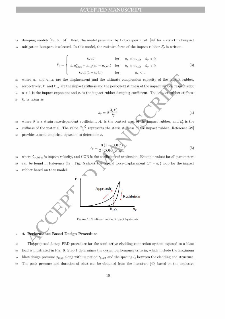
damping models [49, 50, 51]. Here, the model presented by Polycarpou et al. [49] for a structural impact179
mitigation bumpers is selected. In this model, the resistive force of the impact rubber Fr is written:180
Fr =
krunr for ur < ur,ult ur > 0
krunr,ult + kr,y(ur − ur,ult) for ur > ur,ult ur > 0
krunr (1 + crur) for ur < 0
(3)
where ur and ur,ult are the displacement and the ultimate compression capacity of the impact rubber,181
respectively; kr and kr,y are the impact stiffness and the post-yield stiffness of the impact rubber, respectively;182
n > 1 is the impact exponent; and cr is the impact rubber damping coefficient. The impact rubber stiffness183
kr is taken as184
kr = βArk
′r
lnr(4)
where β is a strain rate-dependent coefficient, Ar is the contact area of the impact rubber, and k′r is the185
stiffness of the material. The valueArk
′r
lnrrepresents the static stiffness of the impact rubber. Reference [49]186
provides a semi-empirical equation to determine cr187
cr =3(1− COR2
)
2 · COR · urubber(5)
where urubber is impact velocity, and COR is the coefficient of restitution. Example values for all parameters188
can be found in Reference [49]. Fig. 5 shows the typical force-displacement (Fr - ur) loop for the impact189
rubber based on that model.190
Figure 5: Nonlinear rubber impact hysteresis.
4. Performance-Based Design Procedure191
The proposed 3-step PBD procedure for the semi-active cladding connection system exposed to a blast192
load is illustrated in Fig. 6. Step 1 determines the design performance criteria, which include the maximum193
blast design pressure σmax along with its period tblast and the spacing lc between the cladding and structure.194
The peak pressure and duration of blast can be obtained from the literature [40] based on the explosive195
10

ACCEPTED MANUSCRIPT
ACCEPTED MANUSCRIP
T
charge mass and the standoff distance. Step 2 consists of designing the dynamic parameters of the cladding196
system, including mc, cc, kc, and Fc, and obtaining the maximum displacement of the cladding uc,max based197
on transfer function H1 to be compared with the performance parameter lc from Step 1. If uc,max ≤ lc198
the cladding will not collide with the structure, and the design of the impact rubber can be based on fail-199
safe requirements if the cladding will also not collide with the rubber (uc,max ≤ (lc − lr)). Otherwise, if200
the cladding is to collide with any element, Step 3 is then used to design the impact rubber design. The201
rubber thickness lr will be designed in order to dissipate energy with a prescribed maximum compression of202
ur,max, obtained through transfer functions H2 and H3. If ur,max ≤ lc is satisfied, then the design procedure203
is finished. Otherwise, three design options could be considered: (1) change the allowable spacing lc, (2)204
change the dynamic parameters of the cladding system, or (3) iterate on the rubber thickness lr. The205
proposed PBD procedure is conducted using an SDOF system, and design parameter values will be selected206
from analytical solutions. It is assumed that the peak dynamic response of cladding panel to blast will occur207
at the first quarter cycle, and the dynamics of the structure can be assumed negligible during the maximum208
cladding response (i.e. there will be a delay between the maximum response of the cladding and that of209
the building due to high-speed load transfer). Although numerical solutions are more exact, the analytical210
solution would allow designers to quickly select design parameters, therefore enabling a holistic integration211
of the device within the structural design stage. Each step of the procedure is described in detail below.212
4.1. Step 1 : Performance criteria213
The first step is to establish parameters that will define the performance requirements of the cladding214
system. These include the selection of the design blast load, and the allowable gap distance between the215
cladding and structure lc.216
4.1.1. Design blast pressure217
The design blast pressure can be selected based on three parameters: the explosive material, the explosive218
charge weightW , and the standoff distance between the blast source and the targetR. Most severe intentional219
blast threats are vehicle-borne, and the mass of the explosive charge can be estimated based on quantities220
of explosive that can be stored in various vehicles. Reference [52] provides estimated quantities of common221
explosives based on vehicle types. To obtain the resulting blast pressure, the charge mass from different222
explosive material is represented as an equivalent mass of TNT [53].223
The standoff distance R can be based on several factors, including site security, roadway access, and224
topography. The minimum standoff distance for inhabited buildings of conventional construction can be225
directly obtained from Section 2.3.2.2.1 of ASCE/SEI 59-11 [54]. Based on the assumption that the explosive226
consists of TNT, the following equation can be used to relate W and R to the peak incident overpressure227
11

ACCEPTED MANUSCRIPT
ACCEPTED MANUSCRIP
TFigure 6: 3-steps performance based design procedure.
σso [55]:228
σso =1772
Z3− 114
Z2+
108
Z(6)
where σso is in kPa, W is in kg, and Z = R
W13
is the scaled distance with R is in m. The peak reflected229
pressure σmax is230
σmax = Crσso (7)
where Cr is the reflection coefficient defined as [56, 46]231
Cr = 3( σso
101
) 14
(8)
Lastly, the design peak blast force is taken as Fm = Acσmax, and its associated period tblast (in ms)232
12

ACCEPTED MANUSCRIPT
ACCEPTED MANUSCRIP
T
determined from Equation 9 [56]:233
tblast = W 1/310[−2.75+0.27 log(Z)] (9)
4.1.2. Allowable distance cladding-structure234
Typically, cladding panels are connected to the structure through hanger supports to resist gravity loads235
and tieback connections to resist lateral loads. The lateral connections require a minimum spacing lc,min236
between the cladding panel and the structure for their installation, and can be as high as 6 in (15 cm) for237
prefabricated panels [57]. Allowances for rain drainage, mortar droppings, vapor diffusion, and fire/smoke238
spread prevention need to be taken into account as well. Free drainage occurs if the airspace is greater than239
3/8 in (1 cm) [58]. A minimum of 1 in (2.54 cm) airspace is needed to allow quick drying for the wall, thus240
impeding bacteria growth. For cast-in-place or site-installed cladding such as brick veneer, a minimum 2241
inch airspace is recommended to reduce the possibility that the mortar squeezes out into the air space during242
brick laying and makes permanent contact with the structure. In this study, it is assumed that the cladding243
is designed to avoid blowout under blast load; therefore, prefabricated cladding, which is generally more244
robust for lateral loads, is considered. Preliminary design of the spacing lc needs to meet the aforementioned245
requirements with no less than the minimum gap spacing lc,min .246
4.2. Step 2 : Dynamic parameters of cladding system247
The second step in the design is to select the dynamic parameters of the cladding system, including the248
friction capacity of the semi-active connection (used in passive mode). The equation of motion of an SDOF249
representation of the cladding system subjected to a blast load can be written250
mcuc + ccuc + kcuc + Fc = Fm
(1− t
tblast
)for 0 ≤ t ≤ tblast (10a)
mcuc + ccuc + kcuc + Fc = 0 for t ≥ tblast (10b)
251
with the friction force Fc is approximated using the Coulomb model:252
Fc = fcsgn(uc) (11)
where fc is the friction capacity of the cladding connection, and sgn is the sign or signum function:253
sgn(uc) =
−1 if uc < 0
0 if uc = 0
1 if uc > 0
(12)
13

ACCEPTED MANUSCRIPT
ACCEPTED MANUSCRIP
T
Because only the first quarter cycle of the response is considered, Fc = fc. Eq. 10 can be used to254
characterize the dynamics of the cladding system before it collides with the impact rubber. Assuming that255
the first quarter cycle response time T/4 � tblast, Eq. 10 (a) is solved to find the initial conditions for256
uc(tblast) and uc(tblast) which are needed to solve Eq. 10 (b).257
The solution of Eq. 10 (a) can be derived by Duhamels integral,258
uc(t) =1
mωd
∫ t
0
[Fm
(1− τ
tblast
)− fc
]e−ξωn(t−τ) sin[ωd(t− τ)]dτ (13)
where ξ, ωn and ωd are the damping ratio, natural frequency, and damped frequency of the cladding system,259
respectively. The final solution after integration by parts is expressed:260
uc(t) =e−ξωnt
(u0 −
fckc
)cosωdt+
u0 +(u0 − fc
kc
)ξωn
ωdsinωdt
+
fckc
+Fmkc
[1− e−ξωnt
(ξ√
1− ξ2sinωdt+ cosωdt
)]
− Fmkctblast
[t− 2ξ
ωn+e−ξωnt
ωn
(2ξ cosωdt+
2ξ2 − 1√1− ξ2
sinωdt
)](14)
and261
uc(t) =e−ξωnt
[u0 cosωdt−
(u0ωn − fc
kcωn + ξu0√
1− ξ2
)sinωdt
]+Fme
−ξωnt
kc√
1− ξ2sinωdt
− Fmkctblast
[1− e−ξωnt
(cosωdt+
ξ√1− ξ2
sinωdt
)](15)
where 0 ≤ t ≤ tblast. The solutions of Eq. 14 at t = tblast are used as initial condition for Eq. 10 (b). Eq.262
10 (b) can be solved using the summation of the homogenous solution and particular solution:263
uc(t) = e−ξωn(t−tblast)[(uc(tblast)− fc
kc
)cosωd(t− tblast) +
uc(tblast)+(uc(tblast)− fckc
)ξωn
ωdsinωd(t− tblast)
]+ fc
kc(16)
where t > tblast. Eq. 16 is used to find the maximum displacement, which occurs at time t1. Taking the264
derivative of Eq. 16 equal to zero, and the result of t in first cycle can infer to the maximum uc, uc,max.265
t1 =
tan−1
(uc(tblast)
√1−ξ2
(uc(tblast)− fckc
)ωn+ξuc(tblast)
)
ωd+ tblast (17)
14

ACCEPTED MANUSCRIPT
ACCEPTED MANUSCRIP
T
uc,max = e−ξωn(t1−tblast)
√(uc(tblast)− fc
kc
)2
ω2d +
(uc(tblast) +
(uc(tblast)− fc
kc
)ξωn
)2
ωd+fckc
(18)
A dimensionless transfer function H1 is then created to facilitate the design procedure:266
H1 =uc,max
Fm
kc
=uc,max
ust(19)
where ust = Fm
kcis the static displacement from a constant peak blast force Fm.267
The maximum displacement of cladding uc,max can be obtained from Eq. 19 or from the H1 plots as268
demonstrated later in Section 5 (Numerical Simulations). The maximum displacement is used to verify if269
uc,max ≤ lc. If so, an impact rubber bumper with minimum thickness can be designed, and a second check270
can be conducted to ensure that uc,max ≤ (lc − lr). Otherwise, the impact rubber needs to be carefully271
designed under Step 3.272
4.3. Step 3: Parameters of impact rubber273
An impact rubber of length lr (Fig. 3 (a)) is used to prevent the cladding system from colliding with the274
structure. Step 3 consists of sizing this rubber bumper. The design process starts with a second transfer275
function H2276
H2 =Istructure
Iblast=mcurubber12Fmtblast
(20)
where urubber is the solution of the time derivative of Eq. 18 for t = trubber, which represents the time of277
impact with the impact bumper, Iblast is the impulse of the initial blast and Istructure is the momentum of278
the cladding when it hits the rubber. The impact velocity of the cladding can be calculated using Eq. 18,279
which in turn will be used calculating the maximum deformation of the rubber.280
To obtain the analytical solution of maximum rubber deformation, the rubber model is represented as a281
linear stiffness element to provide a more convenient mathematical form [2]. The mass of the rubber bumper282
is neglected, and the bumper will only provide additional resistant force when impacted by the cladding283
panel. Note that although a linear stiffness element cannot dissipate energy during a full cycle of harmonic284
motion, it can still be used to represent the rubber dynamics since only the gap-closing phase is considered.285
To do so, the hysteresis of the impact rubber (Fig. 5) can be compared to the hysteresis of a linear stiffness286
element in the approaching phase. The impact rubber is approximated using287
Fr = kequr (21)
15

ACCEPTED MANUSCRIPT
ACCEPTED MANUSCRIP
T
where Fr is the damping force, keq is the linear stiffness coefficient, and ur is the deformation of the impact288
rubber. Assuming a periodic excitation, the response of the equivalent system is written:289
ur(t) = ur sin(ωt) (22)
where ur is the amplitude of periodic excitation. To avoid the case of exceeding the ultimate compression290
capacity ur,ult in Fig. 5, ur is assumed to be half of the thickness of impact rubber due to ur,ult = 80%lr291
reported in Reference [49]. Eq. 21 becomes292
Fr = kequr sin(ωt) (23)
The energy dissipation of the impact rubber Wr for this quarter cycle response using this equivalent293
energy dissipation representation is expressed294
Wr =
∫ ur
0
kequrdur
=1
2kequ
2r
(24)
In addition, the energy dissipation of the impact rubber can be taken as the area under the gap-closing295
phase curve. From Eq. 3, FAr represents the impact force when cladding is in the gap-closing phase, and296
FRr represents the force in restitution phase. To simplify the integration, an integer value is used for the297
exponent. Neglecting the post yield phase of impact rubber, the energy dissipation in the approaching phase298
can be computed using Polycarpou’s dynamic model for rubber (Eq. 3):299
Wr =
∫ ur
0
FAr duc
=
∫ ur
0
kru2.65r dur
=1
3.65kru
3.65r
(25)
Equating Eq. 24 and Eq. 25 gives300
keq =2kru
1.65r
3.65(26)
16

ACCEPTED MANUSCRIPT
ACCEPTED MANUSCRIP
T
Figure 7: Equivalent linear stiffness hysteresis.
The equivalent energy dissipation concept is illustrated in Fig. 7. The red triangle area represents energy301
dissipation from the linear stiffness element and the gray shaded area represents the energy dissipation from302
the impact rubber, where both areas are equal. Eq. 10 (b) is modified to include the dynamics of the impact303
rubber using the equivalent stiffness concept:304
muc(t) + cuc(t) + (k + keq)uc(t) = −fc (27)
where t > trubber. The rubber deformation follows the cladding displacement from the point where uc =305
uc,max. The analytical solution for the rubber deformation is similar to Eq. 16, but with knew = keq + kc,306
where ξr and ωdr are the modified damping ratio and damped frequency.307
ur(t) =e−ξrωdr(t−trubber)
[−fc + kcuc(trubber)
knewcosωdr(t− trubber)
]
+ e−ξrωdr(t−trubber)
[uc(trubber)knew − (fc + kcuc(trubber)) ξrωr
knewωdrsinωdr(t− trubber)
]+fc + kcuc(trubber)
knew
(28)
where uc(trubber) = lc − lr is the space between the cladding element and the impact rubber. Using the308
analytical solution from Eq. 28 and the time of maximum deformation ur,max, a third transfer function H3309
is obtained:310
t2 =
tan−1
(uc(trubber)knew
√1−ξ2r
−fcωr−kcuc(trubber)ωr+ξrknewuc(trubber)
)
ωdr+ trubber (29)
ur,max = e−ξrωdr(t2−trubber)
√(uc(trubber)kc+fc)2ω2
dr+(uc(trubber)knew−(uc(trubber)kc+fc)ξrωr)2
ωdrknew+ fc+kcuc(trubber)
knew(30)
H3 =ur,max
ust(31)
17

ACCEPTED MANUSCRIPT
ACCEPTED MANUSCRIP
T
where ust = Fm
kcis the static deformation. Transfer function H3 provides the deformation of the impact311
rubber based on the design parameters selected under Steps 1 and 2, with the objective to obtain a rubber312
deformation smaller than its design thickness lr. Otherwise, other design parameters need to be selected313
and the PBD procedure be iterated, as explained earlier.314
5. Numerical Simulations315
In this section, numerical simulations are conducted to verify the proposed PBD methodology. Simu-316
lations are based on a 1:4 scale six-story three-bay structure equipped with cladding panels spanning each317
floor. This structure was selected due to the availability of parameters and results found in the literature318
[3, 57], in which the authors studied an advanced passive energy-dissipating cladding connector for seis-319
mic design. Here, we used the cladding panel material consistent with [57], and replaced the connector by320
the proposed semi-active connection. Each cladding panel is attached to the structure using two tie back321
connectors and two bearing supports. The semi-active connection is installed as a replacement to tie back322
connectors, and only the bearing connectors are assumed to provide lateral stiffness and inherent damping323
between the cladding and the structure (kc and cc, respectively).324
18

ACCEPTED MANUSCRIPT
ACCEPTED MANUSCRIP
T
5.1. Model assumption325
5.1.1. 18DOF system326
Figure 8: Simulated structure with cladding panels.
The 18DOF representation is illustrated in Fig. 8, which contains one translational DOF per floor, and327
two translational DOF per connection between the cladding and structure. Each cladding panel is modeled328
as a rigid bar of mass mc and has two degree of freedoms at either end connected to the structure. Again,329
the nonlinear response of the cladding will be considered in future work, and the assumption of a rigid bar330
is consistent with current approaches for conservatively calculating the base shear and cladding-to-structure331
load transfer for buildings under blast loading [45, 46]. The first cladding element spanning between ground332
level and the first floor has its lower semi-active connection directly attached to the ground. Details of the333
cladding connections are schematized in Fig. 3 (a). The dynamic properties of the structure and cladding334
elements are listed in Table 1, based on the properties provided in Reference [57].335
19

ACCEPTED MANUSCRIPT
ACCEPTED MANUSCRIP
T
Table 1: Dynamic properties of cladding structure [57]
floor mass stiffness damping cladding mass
(kg) (kN/m) (kN·s/m) (kg)
6 3175 3000 16.32 450
5 3175 3000 16.32 450
4 3175 3000 16.32 450
3 3175 3000 16.32 450
2 3175 3000 16.32 450
1 3175 3000 16.32 450
The equation of motion for the 18DOF system has the form336
Mu + Cu + Ku = EpP + EfF (32)
where u ∈ R18×1 is the displacement vector, P ∈ R12×1 is the blast loading input vector, F ∈ R12×1 is the337
control force vector including the friction force and rubber damping force, M ∈ R18×18,C ∈ R18×18,K ∈338
R18×18 are the mass, damping, and stiffness matrices, respectively, and Ep ∈ R18×12, and Ef ∈ R18×12 are339
the blast loading and control input location matrices, respectively.340
The state-space representation of Eq. (32) is given by341
U = AU + BpP + BfF (33)
where U = [ u u ]T ∈ R36×1 is state vector and342
A =
0 I
−M−1K −M−1C
36×36
Bp =
0
M−1Ep
36×12
Bf =
0
M−1Ef
36×12
where I is an 18× 18 identity matrix.343
Table 2: Comparison of modal properties
mode reported [57] (Hz) model (Hz) difference (%) model Γ (%)
first 1.17 1.17 0.00 86.96
second 3.88 3.47 −10.57 8.91
20

ACCEPTED MANUSCRIPT
ACCEPTED MANUSCRIP
T
Table 2 compares modal parameters between the values reported in [57] and the ones from the 18DOF344
model. The first mode of the model matches the first mode of the six-story building, and the modal345
participation factor Γ shows that the first mode largely dominates the response of the 18DOF representation.346
Two design blast loads are considered for this study. The first is based on a 500-kg mass of TNT (approximate347
explosive mass in a closed van delivery method [52]) at a standoff distance of 25 m. This load will be used in348
Sections 5.2 and 5.3 to compare the proposed analytical solution with the numerical results and demonstrate349
the PBD procedure. A smaller charge weight of 100-kg of TNT (approximate explosive mass in a compact350
car trunk delivery method [52]) at the same 25-m standoff will be introduced in Section 5.4 to evaluate the351
performance of the proposed model and procedure for a more moderate blast load. There is a greater potential352
for nonlinear cladding response due to the 500-kg charge than the 100-kg charge, and comparing their effects353
will evaluate the effectiveness of the proposed connections for a range of blast reaction magnitudes.354
The amplitude of blast load Fm for both charge weights are calculated using Eq.7 based on the maximum355
blast pressure σmax and a total cladding panel area Ac of 3.33 m2 at each floor. Parameter values of the356
500-kg design blast load for each nodes are listed in Table 3 (values for the 100-kg charge will be provided357
later in Section 5.4). The resulting values σmax are within a typical range σcap as discussed in Section 3.2.358
The pressure is taken as a constant between two half floors, resulting in the blast load equal for adjacent359
connections (p4 = p5 in Fig. 8, for instance).360
Table 3: Design blast load (500-kg TNT) for 18DOF system
node R (m) Z (m/kg1/3) σmax (kPa) Fm (kN) tblast (ms)
u7 25.00 3.15 224.00 370.67 24
u8 25.27 3.18 218.05 359.78 24
u9 25.27 3.18 218.05 359.78 24
u10 26.05 3.28 200.25 330.42 25
u11 26.05 3.28 200.25 330.42 25
u12 27.30 3.44 176.03 290.45 25
u13 27.30 3.44 176.03 290.45 25
u14 28.97 3.65 150.29 247.98 25
u15 28.97 3.65 150.29 247.98 25
u16 30.98 3.90 126.37 208.50 26
u17 30.98 3.90 126.37 208.50 26
u18 33.27 4.18 105.79 174.56 26
21

ACCEPTED MANUSCRIPT
ACCEPTED MANUSCRIP
T
5.1.2. 2DOF system361
The six story structure is also modeled as 2DOF system by lumping the six structural mass elements ms362
into a single mass (1DOF) and the six cladding mass elements mc into a single cladding element to obtain363
a representation similar to the one schematized in Fig. 3 (b). A structural damping ratio of 2% is assumed.364
A simplified triangular blast load is used for the simulations (p(t)) using blast load parameters calculated365
following the approach described in Section 4.1.1. The peak design blast load Fm used in 2DOF system366
is summation of blast peak load in 18DOF system. Note that this 2DOF system assumption is only used367
for verifying the SDOF approximation and it does not necessarily represent the dynamic of 18DOF system.368
The resulting parameters used for the numerical simulation are listed in Table 4. Remark that a different369
value for kc than the one used in Reference [57] to obtain a more compliant connection to improve energy370
mitigation.371
Table 4: Model parameters for 2DOF representation
parameter value unit
system
ms 19051 kg
ks 1029 kN/m
cs 56 kN·s/m
mc 2700 kg
blast
W 500 kg
R 25 m
Z 2.5 m/kg1/3
σmax 218 kPa
Fm 3419 kN
tblast 24 ms
5.2. Verification of the SDOF approximation372
Before conducting simulations of the 18DOF system, the PBD methodology is first verified for the 2DOF373
representation of the building to demonstrate the assumption that cladding can be designed based on an374
SDOF approximation. The validity of the assumption is investigated through the comparison of transfer375
function plots obtained from the PBD procedure and from numerical simulations. In what follows, the PBD376
transfer functions Hi (i = 1, 2, 3) are compared against the transfer functions of the 2DOF H∗i obtained377
numerically, using a performance metric Hi:378
Hi =Hi −H∗iH∗i
for i = 1, 2, 3 (34)
22

ACCEPTED MANUSCRIPT
ACCEPTED MANUSCRIP
T
First, H1 and H∗1 transfer functions are plotted as functions of the blast duration ratio tblast/Tn for379
different friction capacity ratios fc/Fm in Fig. 9 (a), over the range 0.1% to 3.0%. The performance metric380
H1 is plotted in Fig. 9 (b). The error in H1 is larger for small ratios tblast/Tn, and converges to 0 with381
increasing tblast/Tn. The magnitude of the error increases with increasing friction ratio. Generally, the error382
is positive, which results in an over-estimation of the cladding displacement. The error is negative for a zero383
friction ratio (fc/Fm = 0%), because the blast energy will be transmitted to the structure (no dissipation)384
and the model will underestimate cladding displacement due to the unmodeled displacement of the structure.385
0.1 0.5 1 1.5 2 2.5 30
0.02
0.04
0.06
0.08
0.1
tblast / Tn (%)
tran
sfer
fun
ctio
n
H1
H∗
1
(a)
0.1 0.5 1 1.5 2 2.5 3−5
0
5
10
15
tblast / Tn (%)
H1(%
)
fc/Fm = 0%
fc/Fm = 1%
fc/Fm = 2%
fc/Fm = 3%
(b)
Figure 9: H1 function for ξ = 2%: (a) H1 and H∗1 ; and (b) H1.
Second, transfer function H2 is verified through the investigation of its fitting performance index H2 over386
different values of relative rubber thickness (lc − lr)/ust. Plots are shown in Figs. 10 and 11 for the ratio387
range 1% to 4%, which represents a large range of spacing lc− lr as ust is relatively large under blast load. A388
null value for H2 signifies that the cladding does not collide with the structure. The error H2 is high for H2389
close to 0, and increases with increasing relative rubber thicknesses. The error is also higher for increasing390
friction ratio. In both cases, this high level of error is due to increasing nonlinearities that are not captured391
by the analytical solutions. However, the error is positive in all cases, which signifies that the cladding will392
be over-designed therefore provide additional safety. Also, the error converges to zero with increasing blast393
duration ratio.394
23

ACCEPTED MANUSCRIPT
ACCEPTED MANUSCRIP
T
0.1 0.5 1 1.5 2 2.5 30
0.2
0.4
0.6
0.8
1
tblast / Tn (%)
tran
sfer
fun
ctio
n
H2
H∗
2
(a)
0.1 0.5 1 1.5 2 2.5 30
10
20
30
40
tblast / Tn (%)
H2(%
)
fc/Fm = 0%
fc/Fm = 1%
fc/Fm = 2%
fc/Fm = 3%
(b)
Figure 10: H2 function for ξ = 2% and (lc − lr)/ust = 1% : (a) H2 and H∗2 ; and (b) H2.
0.1 0.5 1 1.5 2 2.5 30
0.2
0.4
0.6
0.8
1
tblast / Tn (%)
tran
sfer
fun
ctio
n
H2
H∗
2
(a)
0.1 0.5 1 1.5 2 2.5 30
10
20
30
40
50
60
70
tblast / Tn (%)
H2(%
)
fc/Fm = 0%
fc/Fm = 1%
fc/Fm = 2%
fc/Fm = 3%
(b)
Figure 11: H2 function for ξ = 2% and (lc − lr)/ust = 4% : (a) H2 and H∗2 ; and (b) H2.
Third, the H3 function is plotted under different friction capacity ratios fc/Fm, relative rubber thickness395
ratios (lc − lr)/ust and impact rubber stiffness ratios kc/kr in Figs. 12 to 15. The error H3 is high when396
rubber has smaller deformations (H3 close to 0). As tblast/Tn increases, the error H3 quickly decreases to397
reach a negative value for a higher relative rubber stiffness or lower ratio kc/kr.398
24

ACCEPTED MANUSCRIPT
ACCEPTED MANUSCRIP
T
0.1 0.5 1 1.5 2 2.5 30
0.01
0.02
0.03
0.04
0.05
tblast / Tn (%)
tran
sfer
fun
ctio
n
H3
H∗
3
(a)
0.1 0.5 1 1.5 2 2.5 3−20
−10
0
10
20
30
40
tblast / Tn (%)
H3(%
)
kc/kr = 1%
kc/kr = 0.1%
kc/kr = 0.01%
kc/kr = 0.001%
(b)
Figure 12: H3 function for ξ = 2%, fc/Fm = 1%, and (lc − lr)/ust = 1% : (a) H3 and H∗3 ; and (b) H3.
0.1 0.5 1 1.5 2 2.5 30
0.005
0.01
0.015
0.02
tblast / Tn (%)
tran
sfer
fun
ctio
n
H3
H∗
3
(a)
0.1 0.5 1 1.5 2 2.5 3−20
−10
0
10
20
30
40
tblast / Tn (%)
H3(%
)
kc/kr = 1%
kc/kr = 0.1%
kc/kr = 0.01%
kc/kr = 0.001%
(b)
Figure 13: H3 function for ξ = 2%, fc/Fm = 1%, and (lc − lr)/ust = 4% : (a) H3 and H∗3 ; and (b) H3.
25

ACCEPTED MANUSCRIPT
ACCEPTED MANUSCRIP
T
0.1 0.5 1 1.5 2 2.5 30
0.01
0.02
0.03
0.04
0.05
tblast / Tn (%)
tran
sfer
fun
ctio
n
H3
H∗
3
(a)
0.1 0.5 1 1.5 2 2.5 3−20
−10
0
10
20
30
40
50
tblast / Tn (%)
H3(%
)
kc/kr = 1%
kc/kr = 0.1%
kc/kr = 0.01%
kc/kr = 0.001%
(b)
Figure 14: H3 function for ξ = 2%, fc/Fm = 3%, and (lc − lr)/ust = 1% : (a) H3 and H∗3 ; and (b) H3.
0.1 0.5 1 1.5 2 2.5 30
0.002
0.004
0.006
0.008
0.01
0.012
0.014
tblast / Tn (%)
tran
sfer
fun
ctio
n
H3
H∗
3
(a)
0.1 0.5 1 1.5 2 2.5 3−10
0
10
20
30
40
50
60
tblast / Tn (%)
H3(%
)
kc/kr = 1%
kc/kr = 0.1%
kc/kr = 0.01%
kc/kr = 0.001%
(b)
Figure 15: H3 function for ξ = 2%, fc/Fm = 3%, and (lc − lr)/ust = 4% : (a) H3 and H∗3 ; and (b) H3.
5.3. Demonstration of PBD procedure399
In this section, the proposed PBD procedure is demonstrated using the six-story structure shown in Fig.400
8. Recall that, similar to Section 5.2, the 500-kg charge size is used to make this comparison. The dynamic401
parameters of the cladding system and impact rubber, at each floor, are designed based on the PBD transfer402
function results Hi (i = 1, 2, 3) obtained in the previous section for an SDOF system.403
Step 1: Performance Criteria404
The design blast load parameters Fm and tblast for each node are taken from Table 3. The spacing lc at405
each floor is set to 0.4 m for the preliminary design, based on the minimum requirements reviewed in Section406
4.1.2.407
26

ACCEPTED MANUSCRIPT
ACCEPTED MANUSCRIP
T
Step 2: Dynamic Parameters of Cladding System408
The mass of each cladding panel mc is taken as fixed, as provided in Reference [57]. Using the H1 plot409
(Fig. 9 (a)) with the assumption of a cladding damping ratio ξ = 2%, a blast duration ratio tblast/Tn = 3%410
with a friction capacity ratio fc/Fm = 1% yields H1 = 0.081. This H1 value is used to compute uc,max at each411
floor using Equation 19. Table 5 lists the results for each node, as well as kc and cc to obtain tblast/Tn = 3%412
and ξ = 2%. With these design parameters, all of the nodes exceed the allowable deformation of 0.4 m,413
necessitating design step 3 for appropriate sizing of the impact rubber.414
Table 5: Cladding connection design parameters from Step 2
node mc (kg) Tn (s) kc (kN/m) cc (kN·s/m) fc (kN) ust (m) uc,max (m)
u7 225 0.76 15.11 7.38×10⁻² 3.71 27.27 2.21
u8 225 0.76 15.11 7.38×10⁻² 3.60 26.62 2.16
u9 225 0.76 15.11 7.38×10⁻² 3.60 26.62 2.16
u10 225 0.76 15.11 7.38×10⁻² 3.30 24.85 2.01
u11 225 0.76 15.11 7.38×10⁻² 3.30 24.85 2.01
u12 225 0.76 15.11 7.38×10⁻² 2.90 22.40 1.81
u13 225 0.76 15.11 7.38×10⁻² 2.90 22.40 1.81
u14 225 0.8 15.11 7.38×10⁻² 2.48 19.74 1.60
u15 225 0.8 13.88 7.07×10⁻² 2.48 19.74 1.60
u16 225 0.8 13.88 7.07×10⁻² 2.09 17.21 1.40
u17 225 0.8 13.88 7.07×10⁻² 2.09 17.21 1.40
u18 225 0.8 13.88 7.07×10⁻² 1.75 14.97 1.21
Step 3: Parameters of Impact Rubber415
For simplicity, both the cladding-structure spacing lc = 0.4 m and the rubber thickness lr are assumed416
constant throughout the height of the structure. The design of lr is based on the blast load at the first floor,417
which represents the worst case scenario. An initial rubber thickness is selected taking (lc − lr)/ust = 1%418
and yielding lr = 0.12m. The ultimate compression capacity is ur,ult = 0.8lr = 0.096m. The value H2 = 0.96419
is obtained from the H2 plot (Fig. 10 (a)) using the design parameters from Step 2 (tblast/Tn = 3%,420
fc/Fm = 1%), which results in uc,max = 2.21m. This value is much higher than the cladding-structure421
spacing lc. Therefore, H3 must be obtained such that H3 ≤ ur,ult/ust = 0.053. Using H3 from Fig. 12 (a), a422
value of kc/kr = 0.001% would satisfy this requirement, with H3 = 0.0025. The resulting maximum rubber423
deflection is ur,max = 0.068 m. Since the maximum deformation of rubber ur,max is smaller than the rubber’s424
design thickness lr, the design is completed. A detailed design of the impact rubbers can be conducted using425
Equation 4 with rubber properties found in Reference [49].426
27

ACCEPTED MANUSCRIPT
ACCEPTED MANUSCRIP
T
5.4. Simulation results427
The 18DOF model is first verified under a design blast excitation of a 500-kg charge. The discrete form428
of a Duhamel integral is used to numerically simulate Eq. (33) [2]:429
U(t+ 1) = eA∆tU(t) + A−1(eA∆t − I)[BfF(t) + BpP(t)] (35)
where ∆t is the time interval used in the simulation, taken as 0.0001s. Fig. 16 is a plot of the maximum430
cladding and rubber displacement results. The maximum rubber and cladding deformations at each node431
are compared with design values lc =0.4m and lr =0.12m. Maximum deformation of rubber reduce from first432
floor (node 8) to top floor (node 18) caused from decreasing peak blast load. All deformations are smaller433
than design values, demonstrating that the proposed PBD procedure from an SDOF system provides an434
adequate design methodology for an MDOF system.435
7 8 9 10 11 12 13 14 15 16 17 18node
0
0.1
0.2
0.3
0.4
defo
rmat
ion
(m)
rubbercladding
Figure 16: Maximum deformation of cladding and rubber.
The performance of proposed connection (“controlled” case) at mitigating inter-story drift and accel-436
eration is also evaluated versus a cladding system attached with conventional connections (“uncontrolled”437
case), where kc is assumed to be infinitely stiff and no lateral stiffness is provided by the cladding [57]. A438
comparison of the time series inter-story displacements at the first and top floors under design blast load439
are plotted in Figs. 17 and 18, as well as the corresponding rubber peak deformations. Results demonstrate440
that proposed cladding system provides great mitigation performance under significant blast excitation. The441
peak deformation of the rubber impact bumpers is larger at the first impact, as expected.442
28

ACCEPTED MANUSCRIPT
ACCEPTED MANUSCRIP
T
0 1 2 3 4 5time (s)
-0.1
-0.05
0
0.05
0.1
inte
r-st
ory
disp
lace
men
t (m
)
controlleduncontrolled
(a)
0 0.1 0.2 0.3 0.4 0.5time (s)
0
0.01
0.02
0.03
0.04
0.05
0.06
rubb
er d
efor
mat
ion
(m)
(b)
Figure 17: (a) Comparison of displacement response at first floor; (b) peak rubber deformation at node 8 (zoom on 0.5s).
0 1 2 3 4 5time (s)
-0.1
-0.05
0
0.05
0.1
inte
r-st
ory
disp
lace
men
t (m
)
controlleduncontrolled
(a)
0 0.1 0.2 0.3 0.4 0.5time (s)
0
0.01
0.02
0.03
0.04
rubb
er d
efor
mat
ion
(m)
(b)
Figure 18: (a) Comparison of displacement response at top floor; (b) peak rubber deformation at node 18 (zoom on 0.5s).
To evaluate the relative effectiveness of the proposed connection under more moderate blast loads (for443
which nonlinear cladding response may realistically be less likely), additional simulations of the 18DOF444
numerical model are conducted using the blast loads due to the 100-kg charge mass of TNT. Parameter445
values of this excitation are calculated based on Section 4.1.1 and are listed in Table 6.446
29

ACCEPTED MANUSCRIPT
ACCEPTED MANUSCRIP
T
Table 6: Simulated blast load (100-kg TNT) for 18DOF system
node R (m) Z (m/kg1/3) σmax (kPa) Fm (kN) tblast (ms)
u7 25.00 5.39 59.49 98.16 28
u8 25.27 5.44 58.20 96.03 28
u9 25.27 5.44 58.20 96.03 28
u10 26.05 5.61 54.67 90.21 28
u11 26.05 5.61 54.67 90.21 28
u12 27.30 5.88 49.75 82.09 29
u13 27.30 5.88 49.75 82.09 29
u14 28.97 6.23 44.35 73.18 29
u15 28.97 6.23 44.35 73.18 29
u16 30.98 6.66 39.11 64.54 30
u17 30.98 6.66 39.11 64.54 30
u18 33.27 7.15 34.40 56.75 30
The maximum inter-story drift and acceleration reductions at each floor resulting from the controlled case447
under various blast excitations are compared and listed in Table 7. The cladding system under 100-kg TNT448
provides higher inter-story reduction values than the 500-kg case below the third floor due to lower peak blast449
load values. Above the third floor, the 500-kg case demonstrates better inter-story drift mitigation since no450
rubber-cladding collision and energy dissipation from impact rubber occur for the 100-kg case. Under both451
blast load scenarios, the decrease of inter-story drift reduction from the first to the third floor are caused by452
a reduced cladding stiffness and friction capacity (Table 5). Above the third floor, the performance increases453
as the peak blast load magnitude rapidly decreases with increasing diagonal standoff. Comparing the overall454
acceleration mitigation shows that the designed cladding system can provide significant improvement for455
different severities of blast excitations. The high acceleration reduction is caused by the absorption of the456
blast reaction at the cladding level.457
30

ACCEPTED MANUSCRIPT
ACCEPTED MANUSCRIP
T
Table 7: Maximum response reduction
floor 500-kg TNT 100-kg TNT
inter-story drift (%) acceleration (%) inter-story drift (%) acceleration (%)
1 28.32 90.93 30.20 89.93
2 26.91 87.19 32.83 86.43
3 31.22 88.54 45.93 88.06
4 47.27 78.42 40.65 82.64
5 58.79 84.81 43.38 85.31
6 67.67 71.68 38.93 79.80
6. Conclusions458
Explosive materials deliver large shock-wave pressures to nearby structures and can cause significant459
damage in a very short duration. Typically, cladding systems for buildings are connected to the structure460
using connections with very high stiffness, which provide direct transfer of blast-induced reactions to the461
structural system. In this paper, a novel semi-active cladding connection is proposed for mitigating this462
high-rate load transfer. Instead of simply providing rigid lateral support for cladding, this new mechanism463
is an active participant in energy dissipation under blast load. A semi-active friction mechanism is used to464
provide a variable damping force, and an impact rubber bumper is utilized to absorb pounding energy for465
large connection displacements.466
A performance-based procedure has been proposed for the design of this new cladding connection. It467
contains three steps: (1) blast load design, (2) cladding and friction device design, and (3) impact rubber468
design. Three dimensionless transfer functions were derived using an equivalent SDOF system. These func-469
tions allow rapid preliminary design of the cladding system and have been verified by numerical simulation470
of the 2DOF system. Results show that the PBD procedure offers adequate design values with positive471
performance metrics in most cases. It is computationally convenient and reasonably accurate to implement472
the design value from the SDOF system for the MDOF system. Negative error values may arise in the design473
of the rubber bumper for a limited range of scenarios, but this can be accommodated by recommending a474
slightly larger design thickness value to provide additional safety.475
Furthermore, the proposed cladding connection was designed and simulated in a six story structure as476
an example for the proposed PBD procedure. A 18DOF system is used as a prototype, and the blast-477
induced performance of the structure with the proposed friction-based connections is compared with that478
using conventional cladding connections. Numerical simulation results show that the proposed cladding479
connection offers significant reductions of blast-induced story displacements and accelerations. Moreover,480
31

ACCEPTED MANUSCRIPT
ACCEPTED MANUSCRIP
T
the simulation results show that the largest rubber deformation occurs in the first cladding impact cycle,481
which supports the assumptions inherent in models associated with the PBD approach. The results of this482
study indicate that this new semi-active cladding system shows promise for practical considerations of blast483
mitigation for buildings.484
Acknowledgments485
This material is based upon the work supported by the National Science Foundation under Grant No.486
1463252 and No. 1463497. Their support is gratefully acknowledged. Any opinions, findings and conclusions487
or recommendations expressed in this material do not necessarily reflect the views of the National Science488
Foundation.489
References490
REFERENCES491
[1] A. Whittaker, R. Hamburger, M. Mahoney, Performance-based engineering of buildings for extreme492
events, in: AISC-SINY Symposium on Resisting Blast and Progressive Collapse, 2003, pp. 55–66.493
[2] J. Connor, S. Laflamme, Structural Motion Engineering, Springer, 2014.494
[3] B. Goodno, J. Craig, L. El-Gazairly, C. Hsu, Use of advanced cladding systems for passive control of495
building response in earthquakes, in: Proceedings, 10th World Conference on Earthquake Engineering,496
July, 1992, pp. 19–24.497
[4] F. Petrini, A. Palmeri, Performance-based design of bridge structures subjected to multiple hazards: a498
review, in: 6th International Conference on Bridge Maintenance, Safety and Management, 2012, pp.499
2040–2047.500
[5] H. Maneetes, A. Memari, Introduction of an innovative cladding panel system for multi-story buildings,501
Buildings 4 (3) (2014) 418–436. doi:10.3390/buildings4030418.502
[6] A. Baird, A. Palermo, S. Pampanin, Controlling seismic response using passive energy dissipating503
cladding connections, in: 2013 NZSEE Conference, 2013.504
[7] C. Wu, L. Huang, D. J. Oehlers, Blast testing of aluminum foam–protected reinforced concrete slabs,505
Journal of Performance of Constructed Facilities 25 (5) (2011) 464–474. doi:10.1061/(asce)cf.506
1943-5509.0000163.507
[8] C. Shim, N. Yun, R. Yu, D. Byun, Mitigation of blast effects on protective structures by aluminum508
foam panels, Metals 2 (4) (2012) 170–177. doi:10.3390/met2020170.509
32

ACCEPTED MANUSCRIPT
ACCEPTED MANUSCRIP
T
[9] C. Amadio, C. Bedon, Blast analysis of laminated glass curtain walls equipped by viscoelastic dissipative510
devices, Buildings 2 (4) (2012) 359–383. doi:10.3390/buildings2030359.511
[10] C. Amadio, C. Bedon, Multiple dissipative devices for blast-resisting cable-supported glazing facades,512
Modelling and Simulation in Engineering 2013 (2013) 1–13. doi:10.1155/2013/964910.513
[11] A. Agrawal, J. Yang, Semiactive control strategies for buildings subject to near-field earthquakes, in:514
Proceedings of SPIE, Vol. 3988, 2000, p. 359.515
[12] J. Yang, A. Agrawal, Semi-active hybrid control systems for nonlinear buildings against near-field earth-516
quakes, Engineering Structures 24 (3) (2002) 271–280.517
[13] W. L. He, A. K. Agrawal, J. N. Yang, Novel semiactive friction controller for linear structures518
against earthquakes, Journal of Structural Engineering 129 (7) (2003) 941–950. doi:10.1061/(asce)519
0733-9445(2003)129:7(941).520
[14] F. Ubertini, Prevention of suspension bridge flutter using multiple tuned mass dampers, Wind and521
Structures 13 (3) (2010) 235–256.522
[15] Y. Chae, J. M. Ricles, R. Sause, Modeling of a large-scale magneto-rheological damper for seismic523
hazard mitigation. part i: Passive mode, Earthquake Engineering & Structural Dynamics 42 (5) (2012)524
669–685. doi:10.1002/eqe.2237.525
[16] F. Ubertini, G. Comanducci, S. Laflamme, A parametric study on reliability-based tuned-mass damper526
design against bridge flutter, Journal of Vibration and Control 23 (9) (2015) 1518–1534. doi:10.1177/527
1077546315595304.528
[17] S. Laflamme, D. Taylor, M. A. Maane, J. J. Connor, Modified friction device for control of large-scale529
systems, Structural Control and Health Monitoring 19 (4) (2011) 548–564. doi:10.1002/stc.454.530
[18] L. Cao, A. Downey, S. Laflamme, D. Taylor, J. Ricles, Variable friction device for structural control based531
on duo-servo vehicle brake: Modeling and experimental validation, Journal of Sound and Vibration 348532
(2015) 41–56. doi:10.1016/j.jsv.2015.03.011.533
[19] L. Cao, S. Laflamme, D. Taylor, J. Ricles, Simulations of a variable friction device for multihazard534
mitigation, Journal of Structural Engineering 142 (12) (2016) H4016001. doi:10.1061/(asce)st.535
1943-541x.0001580.536
[20] T. Vesselenyi, S. Dziac, I. Dziac, M.-J. Manolescu, Fuzzy and neural controllers for a pneumatic actuator,537
International Journal of Computers Communications & Control 2 (4) (2007) 375. doi:10.15837/ijccc.538
2007.4.2368.539
33

ACCEPTED MANUSCRIPT
ACCEPTED MANUSCRIP
T
[21] A. Mehmood, S. Laghrouche, M. E. Bagdouri, Modeling identification and simulation of pneumatic540
actuator for VGT system, Sensors and Actuators A: Physical 165 (2) (2011) 367–378. doi:10.1016/j.541
sna.2010.11.006.542
[22] S. Kannan, H. M. Uras, H. M. Aktan, Active control of building seismic response by energy dissipation,543
Earthquake Engineering & Structural Dynamics 24 (5) (1995) 747–759. doi:10.1002/eqe.4290240510.544
[23] M. Lorenz, B. Heimann, V. Hartel, A novel engine mount with semi-active dry friction damping, Shock545
and Vibration 13 (4-5) (2006) 559–571. doi:10.1155/2006/263251.546
[24] J. N. Yang, A. K. Agrawal, Semi-active hybrid control systems for nonlinear buildings against near-field547
earthquakes, Engineering Structures 24 (3) (2002) 271–280. doi:10.1016/s0141-0296(01)00094-3.548
[25] Y. Kawamoto, Y. Suda, H. Inoue, T. Kondo, Electro-mechanical suspension system considering energy549
consumption and vehicle manoeuvre, Vehicle System Dynamics 46 (sup1) (2008) 1053–1063. doi:550
10.1080/00423110802056263.551
[26] C. Chen, G. Chen, Shake table tests of a quarter-scale three-storey building model with piezoelectric552
friction dampers, Structural Control and Health Monitoring 11 (4) (2004) 239–257. doi:10.1002/stc.553
41.554
[27] L.-Y. Lu, G.-L. Lin, A theoretical study on piezoelectric smart isolation system for seismic protection555
of equipment in near-fault areas, Journal of Intelligent Material Systems and Structures 20 (2) (2008)556
217–232. doi:10.1177/1045389x08091120.557
[28] O. Durmaz, W. W. Clark, D. S. Bennett, J. S. Paine, M. N. Samuelson, Experimental and analytical558
studies of a novel semi-active piezoelectric coulomb damper, in: SPIE’s 9th Annual International Sym-559
posium on Smart Structures and Materials, International Society for Optics and Photonics, 2002, pp.560
258–273.561
[29] Y. L. Xu, C. L. Ng, Seismic protection of a building complex using variable friction damper: Experi-562
mental investigation, Journal of Engineering Mechanics 134 (8) (2008) 637–649. doi:10.1061/(asce)563
0733-9399(2008)134:8(637).564
[30] S. Narasimhan, S. Nagarajaiah, Smart base isolated buildings with variable friction systems:h∞ con-565
troller and SAIVF device, Earthquake Engineering & Structural Dynamics 35 (8) (2006) 921–942.566
doi:10.1002/eqe.559.567
[31] J. Pardo-Varela, J. C. de la Llera, A semi-active piezoelectric friction damper, Earthquake Engineering568
& Structural Dynamics 44 (3) (2014) 333–354. doi:10.1002/eqe.2469.569
34

ACCEPTED MANUSCRIPT
ACCEPTED MANUSCRIP
T
[32] A. Downey, L. Cao, S. Laflamme, D. Taylor, J. Ricles, High capacity variable friction damper based on570
band brake technology, Engineering Structures 113 (2016) 287–298. doi:10.1016/j.engstruct.2016.571
01.035.572
[33] D. Karagiozova, G. Langdon, G. Nurick, Blast attenuation in cymat foam core sacrificial claddings,573
International Journal of Mechanical Sciences 52 (5) (2010) 758–776. doi:10.1016/j.ijmecsci.2010.574
02.002.575
[34] P. Olmati, F. Petrini, K. Gkoumas, Fragility analysis for the performance-based design of cladding wall576
panels subjected to blast load, Engineering Structures 78 (2014) 112–120. doi:10.1016/j.engstruct.577
2014.06.004.578
[35] C. Wu, H. Sheikh, A finite element modelling to investigate the mitigation of blast effects on reinforced579
concrete panel using foam cladding, International Journal of Impact Engineering 55 (2013) 24–33.580
doi:10.1016/j.ijimpeng.2012.11.006.581
[36] L. Linkute, V. Juocevicius, E. R. Vaidogas, A probabilistic design of sacrificial cladding for a blast wall582
using limited statistical information on blast loading, Mechanika 19 (1). doi:10.5755/j01.mech.19.583
1.3621.584
[37] T. Ngo, P. Mendis, A. Gupta, J. Ramsay, Blast loading and blast effects on structures–an overview,585
Electronic Journal of Structural Engineering 7 (2007) 76–91.586
[38] Q. M. Li, H. Meng, Pressure-impulse diagram for blast loads based on dimensional analysis and single-587
degree-of-freedom model, Journal of Engineering Mechanics 128 (1) (2002) 87–92. doi:10.1061/(asce)588
0733-9399(2002)128:1(87).589
[39] M. Larcher, Pressure-time functions for the description of air blast waves, JRC Technical Note (46829).590
[40] The design of concrete structure to resist explosions and weapon effects, Technical Manual TM 5-1300,591
US Department of the Army, Navy and Air Force, Washington DC.592
[41] E. Hinman, P. H. C. Engineers, Blast safety of the building envelope, Whole Building Design Guide,2011.593
[42] Z. Q. Ye, G. W. Ma, Effects of foam claddings for structure protection against blast loads, Journal of594
Engineering Mechanics 133 (1) (2007) 41–47. doi:10.1061/(asce)0733-9399(2007)133:1(41).595
[43] B. Li, T.-C. Pan, A. Nair, A case study of the effect of cladding panels on the response of reinforced596
concrete frames subjected to distant blast loadings, Nuclear Engineering and Design 239 (3) (2009)597
455–469. doi:10.1016/j.nucengdes.2008.12.003.598
35

ACCEPTED MANUSCRIPT
ACCEPTED MANUSCRIP
T
[44] H. Zhao, H. Yu, Y. Yuan, H. Zhu, Blast mitigation effect of the foamed cement-base sacrificial599
cladding for tunnel structures, Construction and Building Materials 94 (2015) 710–718. doi:10.1016/600
j.conbuildmat.2015.07.076.601
[45] C. Ewing, C. Guillin, R. Dhakal, J. Chase, Spectral analysis of semi-actively controlled structures602
subjected to blast loading, Structural Engineering and Mechanics 33.603
[46] R. Zhang, B. M. Phillips, Performance and protection of base-isolated structures under blast load-604
ing, Journal of Engineering Mechanics 142 (1) (2016) 04015063. doi:10.1061/(asce)em.1943-7889.605
0000974.606
[47] S. A. Anagnostopoulos, Pounding of buildings in series during earthquakes, Earthquake Engineering &607
Structural Dynamics 16 (3) (1988) 443–456. doi:10.1002/eqe.4290160311.608
[48] R. O. Davis, Pounding of buildings modelled by an impact oscillator, Earthquake Engineering & Struc-609
tural Dynamics 21 (3) (1992) 253–274. doi:10.1002/eqe.4290210305.610
[49] P. C. Polycarpou, P. Komodromos, A. C. Polycarpou, A nonlinear impact model for simulating the611
use of rubber shock absorbers for mitigating the effects of structural pounding during earthquakes,612
Earthquake Engineering & Structural Dynamics 42 (1) (2012) 81–100. doi:10.1002/eqe.2194.613
[50] P. Komodromos, P. C. Polycarpou, L. Papaloizou, M. C. Phocas, Response of seismically isolated614
buildings considering poundings, Earthquake Engineering & Structural Dynamics 36 (12) (2007) 1605–615
1622. doi:10.1002/eqe.692.616
[51] S. Muthukumar, R. DesRoches, A hertz contact model with non-linear damping for pounding simulation,617
Earthquake Engineering & Structural Dynamics 35 (7) (2006) 811–828. doi:10.1002/eqe.557.618
[52] H. Draganic, V. Sigmund, Blast loading on structures., Tehnicki Vjesnik/Technical Gazette 19 (3) (2012)619
643–652.620
[53] D. O. Dusenberry, Handbook for blast-resistant design of buildings, Wiley Online Library, 2010.621
[54] Blast protection of building, American Society of Civil Engineers-Structural Engineering Institute622
(ASCE/SEI) 59-11, Reston, VA, 2011.623
[55] C. Mills, The design of concrete structure to resist explosions and weapon effects, in: Proceedings of624
the 1st Int. Conference on Concrete for Hazard Protections, 1987, pp. 61–73.625
[56] N. Lam, P. Mendis, T. Ngo, Response spectrum solutions for blast loading, Electronic Journal of626
Structural Engineering 4 (2004) 28–44.627
36

ACCEPTED MANUSCRIPT
ACCEPTED MANUSCRIP
T
[57] J.-P. Pinelli, J. I. Craig, B. J. Goodno, Energy-based seismic design of ductile cladding systems, Journal628
of Structural Engineering 121 (3) (1995) 567–578. doi:10.1061/(asce)0733-9445(1995)121:3(567).629
[58] J. Lstiburek, Moisture control handbook: principles and practices for residential and small commercial630
buildings, John Wiley & Sons, 1996.631
37