performance analysis of mesh based enterprise network
TRANSCRIPT

Performance Analysis of Mesh Based
Enterprise Network using RIP, EIGRP and OSPF
Routing Protocols
AuthorMd. Humayun Kabir*, Md. Ahasan Kabir, Md. Saiful Islam, Mohammad Golam Mortuza, Mohammad Mohiuddin
11/4/2021 ECSA-8 1
Outline
✓ Introduction
✓ Problem Statement
✓ Contribution of this Research
✓ Concept of the Mesh-based Enterprise Wireless Sensor Network Proposed
✓ Scenario Analysis
✓ Testing Scenario
✓ Data Transmitting
✓ Performance Analysis Parameter
✓ Analysis Results
✓ Conclusion & Future Scope
11/4/2021 ECSA-8 2
Introduction
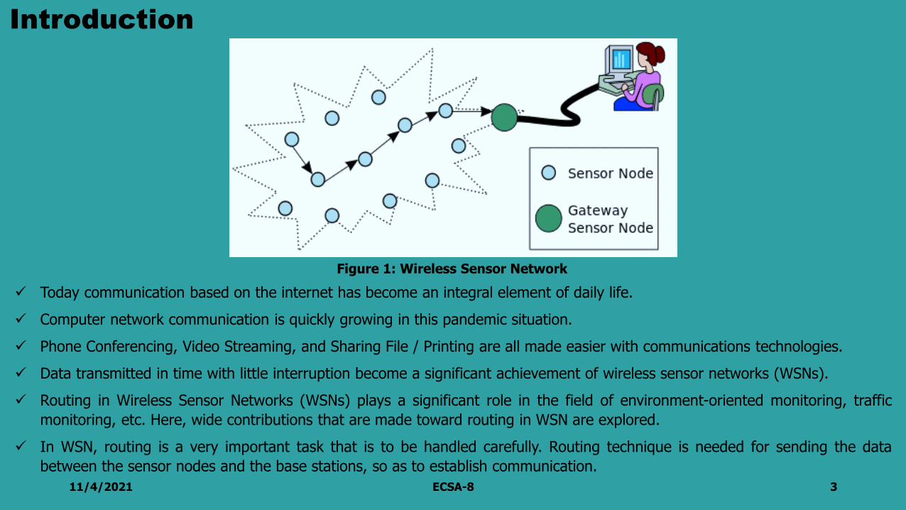
✓ Today communication based on the internet has become an integral element of daily life.
✓ Computer network communication is quickly growing in this pandemic situation.
✓ Phone Conferencing, Video Streaming, and Sharing File / Printing are all made easier with communications technologies.
✓ Data transmitted in time with little interruption become a significant achievement of wireless sensor networks (WSNs).
✓ Routing in Wireless Sensor Networks (WSNs) plays a significant role in the field of environment-oriented monitoring, traffic
monitoring, etc. Here, wide contributions that are made toward routing in WSN are explored.
✓ In WSN, routing is a very important task that is to be handled carefully. Routing technique is needed for sending the data
between the sensor nodes and the base stations, so as to establish communication.
11/4/2021 ECSA-8 3
Figure 1: Wireless Sensor Network

11/4/2021 ECSA-8 4
Figure 2 Architecture of the routing protocol in WSN
Fig. 2 explains the routing protocol of the wireless sensor networks [2].

Problem Statement
11/4/2021 ECSA-8 5
✓ The flow of detected data is compulsory from a number of sources to a specific base station.
✓ The created data traffic has significant redundancy in most of cases.
✓ The time needed to transmit the sensed data is required to be as little as possible in above cited WSNapplications.

✓ This research mainly aims to minimize the routing delay problems by determine the optimumpath/route of data packets to be transmitted from source to destination.
✓ To find delay-less routing protocols for the massive mesh-based enterprise wireless sensor network.
✓ To create two network topologies with RIP, EIGRP, and OSPF to analyze their performance.
✓ To simulate various network topologies using packets, transfer, and observe the performance differencesbetween the OSPF, EIGRP, and RIP networks.
11/4/2021 ECSA-8 6
Contribution of this Research

Concept of the Mesh-based Enterprise Wireless Sensor Network
11/4/2021 ECSA-8 7
Figure 3. Mesh-based Enterprise Wireless Sensor Network.
✓ It is a core network design with numerous redundantconnections between network nodes.
✓ Thus, if any nodes fail in a wireless mesh architecture, thereare many alternative ways to communicate with each node.
✓ A mesh network combines other topologies such as Star,Ring, and Bus in a hybrid topology. Also, specific WANarchitectures, like the Internet, use mesh routing, whichworks even in disaster [1].
✓ Full mesh and partial mesh are the two mesh topologies.When every node in a network has a connection linking it toevery other node, this is referred to as full mesh topology.
Scenario Analysis
11/4/2021 ECSA-8 8
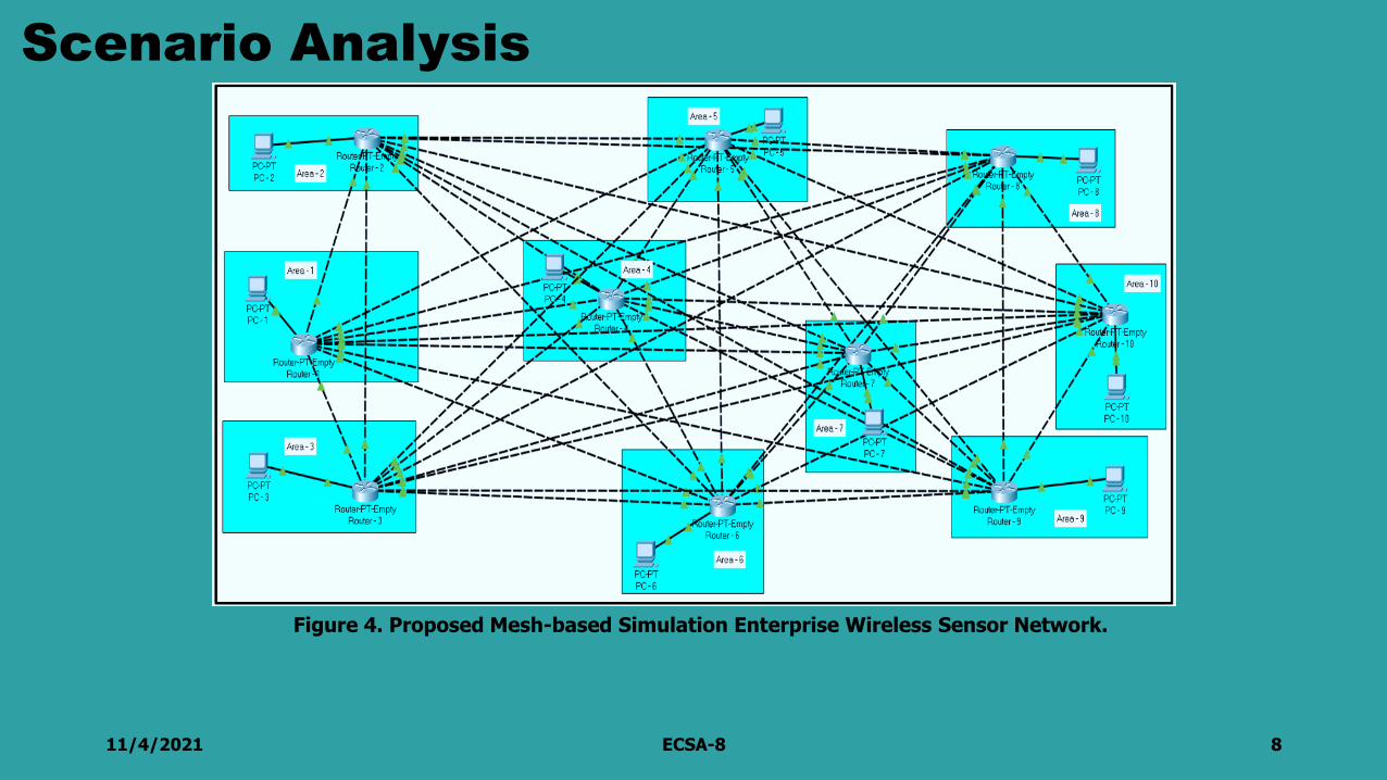
Figure 4. Proposed Mesh-based Simulation Enterprise Wireless Sensor Network.

11/4/2021 ECSA-8 9
The underlying structure created a complete lattice geography reconstruction using ten routers; each router directly connected to its neighbors' routers. Additionally, each of these routers will serve a single client, as seen in Table 1.
Table 1. IP Configuration in Router Port and Client.Router – 1 Router – 2 Router – 3 Router – 4 Router – 5
G0/0 193.169.1.1 G0/0 193.169.11.1 G0/0 193.169.20.1 G0/0 193.169.30.1 G0/0 193.169.40.1
G1/0 193.169.2.1 G1/0 193.169.2.2 G1/0 193.169.3.2 G1/0 193.169.4.2 G1/0 193.169.5.2
G2/0 193.169.3.1 G2/0 193.169.12.1 G2/0 193.169.12.2 G2/0 193.169.13.2 G2/0 193.169.14.2
G3/0 193.169.4.1 G3/0 193.169.13.1 G3/0 193.169.22.1 G3/0 193.169.22.2 G3/0 193.169.23.2
G4/0 193.169.5.1 G4/0 193.169.14.1 G4/0 193.169.23.1 G4/0 193.169.31.1 G4/0 193.169.31.2
G5/0 193.169.6.1 G5/0 193.169.15.1 G5/0 193.169.24.1 G5/0 193.169.32.1 G5/0 193.169.41.1
G6/0 193.169.7.1 G6/0 193.169.16.1 G6/0 193.169.25.1 G6/0 193.169.33.1 G6/0 193.169.42.1
G7/0 193.169.8.1 G7/0 193.169.17.1 G7/0 193.169.26.1 G7/0 193.169.34.1 G7/0 193.169.43.1
G8/0 193.169.9.1 G8/0 193.169.18.1 G8/0 193.169.27.1 G8/0 193.169.35.1 G8/0 193.169.44.1
G9/0 193.169.10.1 G9/0 193.169.19.1 G9/0 193.169.28.1 G9/0 193.169.36.1 G9/0 193.169.45.1
PC 193.169.1.10 PC 193.169.11.10 PC 193.169.20.10 PC 193.169.30.10 PC 193.169.40.10
Router – 6 Router – 7 Router – 8 Router – 8 Router – 10G0/0 193.169.50.1 G0/0 193.169.60.1 G0/0 193.169.70.1 G0/0 193.169.80.1 G0/0 193.169.90.1
G1/0 193.169.6.2 G1/0 193.169.7.2 G1/0 193.169.8.2 G1/0 193.169.9.2 G1/0 193.169.10.2
G2/0 193.169.15.2 G2/0 193.169.16.2 G2/0 193.169.17.2 G2/0 193.169.18.2 G2/0 193.169.19.2
G3/0 193.169.24.2 G3/0 193.169.25.2 G3/0 193.169.26.2 G3/0 193.169.27.2 G3/0 193.169.28.2
G4/0 193.169.32.2 G4/0 193.169.33.2 G4/0 193.169.34.2 G4/0 193.169.35.2 G4/0 193.169.36.2
G5/0 193.169.41.2 G5/0 193.169.42.2 G5/0 193.169.43.2 G5/0 193.169.44.2 G5/0 193.169.45.2
G6/0 193.169.51.1 G6/0 193.169.51.1 G6/0 193.169.52.2 G6/0 193.169.53.2 G6/0 193.169.54.2
G7/0 193.169.52.1 G7/0 193.169.61.1 G7/0 193.169.61.2 G7/0 193.169.61.2 G7/0 193.169.63.2
G8/0 193.169.53.1 G8/0 193.169.62.1 G8/0 193.169.71.1 G8/0 193.169.71.2 G8/0 193.169.72.2
G9/0 193.169.54.1 G9/0 193.169.63.1 G9/0 193.169.72.1 G9/0 193.169.81.1 G9/0 193.169.81.2
PC 193.169.50.10 PC 193.169.60.10 PC 193.169.70.10 PC 193.169.80.10 PC 193.169.90.10

Testing Scenario
11/4/2021 ECSA-8 10
Figure 5. Testing Process of Mesh Network Topology
The network topology is testing the scenario shown in figure 5.The conventional procedures are:✓ These steps are used to receive and send network information.✓ Second, finding the best route to a location and adding it to the routing data-base.✓ Finally, it is a procedure to identifying, responding, and notifying network changes.

11/4/2021 ECSA-8 11
Afterward, the process of transmitting data packets from one network to another is carried out via ping test andtraceroute, as seen in Figure 6
Figure 6. Packet Sending and Tracert Checking on Route 1 to Route 10 using RIP
Data Transmitting

11/4/2021 ECSA-8 12
Afterward, the process of transmitting data packets from one network to another is carried out via ping test andtraceroute, as seen in Figure 7
Figure 7. Packet Sending and Tracert Checking on Route 1 to Route 9 using EIGRP

11/4/2021 ECSA-8 13
Afterward, the process of transmitting data packets from one network to another is carried out via ping test andtraceroute, as seen in Figure 8
Figure 8. Packet Sending and Tracert Checking on Route 1 to Route 8 using OSPF

Time Testing
11/4/2021 ECSA-8 14
Table 2. Router Full Mesh RIP / EIGRP / OSPF.
Full Mesh
Client PC Client PC RIP EIGRP OSPF
PC – 1 PC – 2 8 ms 1 ms 2 ms
PC – 1 PC – 3 6 ms 7 ms 2 ms
PC – 1 PC – 4 8 ms 8 ms 3 ms
PC – 1 PC – 5 8 ms 8 ms 5 ms
PC – 1 PC – 6 7 ms 8 ms 6 ms
PC – 1 PC – 7 8 ms 9 ms 4 ms
PC – 1 PC – 8 9 ms 9 ms 9 ms
PC – 1 PC – 9 11 ms 9 ms 5 ms
PC – 1 PC – 10 12 ms 8 ms 6 ms
Table 3. Router Half Mesh RIP / EIGRP / OSPF
Half Mesh
Client PC Client PC RIP EIGRP OSPF
PC – 1 PC – 2 12 ms 3 ms 2 ms
PC – 1 PC – 3 7 ms 2 ms 2 ms
PC – 1 PC – 4 8 ms 5 ms 3 ms
PC – 1 PC – 5 9 ms 4 ms 3 ms
PC – 1 PC – 6 8 ms 8 ms 4 ms
PC – 1 PC – 7 8 ms 9.66 ms 5 ms
PC – 1 PC – 8 9 ms 9.33 ms 3 ms
PC – 1 PC – 9 9 ms 9.66 ms 3 ms
PC – 1 PC – 10 10 ms 8.33 ms 5 ms

11/4/2021 ECSA-8 15
The performance of the network as a whole is measured by analyzing the following parameters [3 – 6]:
Latency
Latency is calculated using the following formula:
𝐿𝑎𝑡𝑒𝑛𝑐𝑦 =𝑅𝑜𝑢𝑛𝑑 𝑇𝑟𝑖𝑝 𝑇𝑖𝑚𝑒
2
Round-trip Time
Round-trip time is also called round-trip delay, is the time required for a signal pulse or packet to travel from a
specific source to a specific destination and back again.
Throughput
Throughput is calculated using the following formula:
𝑇ℎ𝑟𝑜𝑢𝑔ℎ𝑝𝑢𝑡 =𝐿𝑎𝑡𝑒𝑛𝑐𝑦
𝑃𝑎𝑐𝑘𝑒𝑡 𝑆𝑖𝑧𝑒
Throughput is the amount of data moved successfully from one place to another in a given time period, and
typically measured in bits per second (bps), as in megabits per second (Mbps) or gigabits per second (Gbps).
Performance Analysis Parameter

Analysis Results
11/4/2021 ECSA-8 16
A simulation duration of four minutes for voice, HTTP, and video data transport is specified for LAN-to-server andserver-to-LAN configurations in full and half mesh RIP, OSPF, and EIGRP.
Figure 9a. The Average Voice Packet end-to-end Latency, 9b. The Average Value of HTTP Page Response Time, 9c. The Average Video Packet end-to-end Latency.

11/4/2021 ECSA-8 17
Figure 10 illustrates the average network throughput for three protocols. The OSPF protocols produce betterthroughput than any of the other protocols evaluated in this test case. The following result is the findings of theanalysis based on the experiments.
Figure 10. The Average Point to Point Throughput (bit/sec).

Conclusion
11/4/2021 ECSA-8 18
✓ In a wireless communication network, identify the optimal path from the sensor node to the destination is more difficult.
✓ The routing protocols help to find an optimal path between source and destination nodes and minimize these
difficulties.
✓ The optimal path selection depends upon several factors.
✓ This research discusses and analyzes different parametric aspects of routing protocols. RIP, EIGRP, and OSPF routing
protocols were analyzed and evaluated via an extensive simulation process using carefully selected parameters to
acquire the features of their routing algorithms.
✓ The measured metrics are voice, HTTP, and video traffic transmitted and received, as well as average end-to-end
latency and average point-to-point throughput.
✓ The protocol RIP has shown the most significant uncertainty, whereas OSPF has demonstrated the lowest latency.
✓ Furthermore, the OSPF protocols attain a better throughput than any other protocols evaluated in this test scenario.
✓ From the above result, we see that the OSPF routing protocol is more suitable for multi-hop wireless sensor networks.
✓ In future research, we will work on simulations with much more realistic topologies and increased optimization accuracy
to enhance and show the efficacy of routing protocols in terms of wireless sensor network performance.

References
11/4/2021 ECSA-8 19
1. Noman Shabbir and Syed Rizwan Hassan (October 4th 2017). Routing Protocols for Wireless Sensor Networks (WSNs),Wireless Sensor Networks - Insights and Innovations, Philip Sallis, IntechOpen, DOI: 10.5772/intechopen.70208.
2. Awan Mahmood, "Performance Analysis of Routing Protocols RIP, EIGRP, OSPF and IGRP using Networks connector",Proceedings of the 1st International Multi-Disciplinary Conference Theme: Sustainable Development and Smart Planning,IMDC-SDSP 2020, Cyperspace, 28-30
3. G. K. Dey, M. M. Ahmed and K. T. Ahmmed, "Performance analysis and redistribution among RIPv2, EIGRP & OSPF RoutingProtocol," 2015 International Conference on Computer and Information Engineering (ICCIE), 2015, pp. 21-24
4. A. Fiade, M. A. Agustian and S. U. Masruroh, "Analysis of Failover Link System Performance in OSPF, EIGRP, RIPV2 RoutingProtocol with BGP," 7th International Conference on Cyber and IT Service Management (CITSM), 2019, pp. 1-7
5. H. K. Putri, L. V. Yovita and R. M. Negara, "Performance analysis of CSI:T routing in a delay tolerant networks," 2017 4thInternational Conference on Electrical Engineering, Computer Science and Informatics (EECSI), 2017, pp. 1-6
6. C. G. Dumitrache, G. Predusca, L. D. Circiumarescu, N. Angelescu and D. C. Puchianu, "Comparative study of RIP, OSPF andEIGRP protocols using Cisco Packet Tracer," 5th International Symposium on Electrical and Electronics Engineering (ISEEE),2017, pp. 1-6

11/4/2021 ECSA-8 20