penetration fracture of ice plate: 2d … · penetration fracture of ice plate: 2d analysis ani)...
TRANSCRIPT
PENETRATION FRACTURE OF ICE PLATE:
2D ANALYSIS ANI) SIZE EFFECT
By Yuan-Neng Li' and Zdenek P. Balant.2 Fellow, ASCE
ABSTRACT: The prohlem of static penetration of an ohject through a sea icc plate i~ studied as a two-dimensional fr:leture problem using linear el:lslic fraetun: mechanics. The iu: sheet floating on watel is modeled as a thin clastic plate resting on Winkler's clastic foundation. The e4uilibrium e4u<ltions arc established by minimizing the potential energy approximated by finite differences in terms of nodal deflections. The growth of radial craek~ is analyzed using the plate bending theory. The fracture process lOne is assumed to he a point in the plane of plate. The maximum load is found to occur when circumferential cfOleks begin to form. which is governed by a strength criterion. As a refinement and extension of a previous idea. a theory of initi;rl crack spacing is proposed to estilll<lte the numher of radial cracks formed during penetration This theory can abo explain the change of the failure mechanism. from failure by formation of circumferential cracks to failure by a conic crack. Particular attention is paid to the size effect. In addition to the size effect descrihed hy a simplified one-dimensional solution in a previous paper. the influence of the difference in the number of radial CI<lcks Oil the sile effect is discovered and analyzed.
INTRODUCTION
When an increasing upward or downward load is applied over a small area of ice plate floating on seawatcr, diffuse cracks first emerge at the other side of the ice plate. Subsequently, several radial cracks develop and propagate with increasing load. The maximum load is reached when circumferential cracks begin to form. After that the load decreases with increasing displacement and the platc wcdges between the radial cracks are broken (Frankenstein 1963; Kerr 1975). BaZant and Li (1':1':14) studied this problem using Nevel's (1959) narrow wedge-beam approximation, which is acceptable when the central angles of the wedges are sufficiently small. To solve the cases with larger wedge angles and to understand the limitations of the narrow wedge-beam approximation, a truly two-dimensional plate analysis must be conducted. To the bcst of our knowledge, there is no analytical solution for an infinite wedge plate with an arbitrary central angle resting on a Winkler's foundation.
The goal of the present study is to present a two-dimensional solution of the floating elastic wedge plate and use it to analyze fracture caused by penetrating objects. Commercial finite element programs for floating elastic plates seem unavailable, therefore, a variational form of the finite difference mcthod is developed. The potential energy, approximated by finite differences, is minimized with respect to nodal deflections. Since regular meshes can be used with a polar coordinate system, the finite difference method appears to be simpler than the finite element method. The finite difference
IRes. Sci. in the Rank of As~1. Prof.. Dept. of Civ. Engrg .. Northwestern llniv .. Evanston, IL 6020X.
2Walter P. Murphy. Prof. of Civ. Engrg. and Mat. Sci .. Northwestern Univ .. Evanston, IL.
Note. Discussion open until December I, 1':194. To extend the closing date one month, a written request must be filed with the ASCE Manager of Journals. The manuscript fur this paper was submitted for review and possible publication Oil
January II, 19':13. This paper is part of the Journal of Engineering Mechonin. Vol. 12(), No.7, July, 1994. C!)ASCE. ISSN 07l3-93l)1)!94!0007-14XI!$2(}() + $.25 per page. Paper No. 54()7.
1481

method has hccn used to ~olvc platc pJOhkllls Ic.g. Selvadlllai (1\)7\))]: however, its clas:-,ical form does not seem vcry suitahle for the prescnt problem.
With thc variational principle, the static houndary condition is taken care of automatically and the m~ltrix of cquilihrium equations is symmelI ic, which yields considerable savings in computational effort. By using polar coordinates, the wedge can bc treated as a rectangular region, which means that the geometric shape of thc wedgc can be Illodeled exactly, and thc coding itself becomes much easier. Thc finite differcnce Illcthod h~lsed on a variational principle is a well-documcnted nUllll'lical approach Ie .g. hnsythc (1l)6()) and Iiall (I()<)())j. Most applications are for the second-order partial differential equations. After this paper was suhmitted, one of the reviewers hrought our attention to the work by Bushnell (1t)7~), who IIsed a similar variational finite difference melhod to solve various prohlems with shcll st ruct u rcs.
The second goal is to analyze the fracture process two-dimensionallv, determinc the angular spacing and growth of the radial cracks, est;lhlish the relation betwl'cn thc pl;llL' thickness and the nUlIlher of radial cracks, and, most importantly, clarify the Sill' effect. Sincc the ice sheet may fail hy a conic crack under the load, which is obviously a three-dimensional phenomenon, we will also attempt to provide some information on this type of failure.
VARIATIONAL PRINCIPLE AND ITS FINITE DIFFERENCE APPROXIMATION
Consider an ice plate [Fig. J(a)] with polar coordinates (r, 0), Iloating on water and suhjected to a vertical load I' that is uniforlllly distributed along the circllmference of a circle with radius an. Based on ob'il'lvations, it is as~umed that thc load produces II radial cracks of equal length II from the center, forming pl<lte wedges of equal angles \flu ,=c 2TrllI. The seawater, of unit weight fl, acts exactly as an el;lstic (Winkler-type) fOllndation, hecause the blloyallcy i~ exact Iy pmport ion a I to ddkct iOll. W l' ;1~~IIII1l' t h~1 t till'
~, ~ ~
>,~;~ ; I [ ~ , :::::. ~, " ", :::::""
I· ~12ao
\/ ----1( ~)f---
/\ l-a --i
\ "
/' \ ' \
~
r
FIG. 1. (a) Floating Ice Sheet Subjected to Vertical Load; (b) Wedge Geometry
1482
defiectiollS "re not \0 large that w;ltn could !Iood till' top ()f the pLltc when it deflects dowllward. or the plate would !lot he liftl'd off of the watn surface when it deflccts upward.
Let f) ,,. I:'II( I - 112) be the plate stiffness. I ~c 11'112 the IllOl1lent of the inertia. and II .~ thickness of the plate. I:' "" Young's lIlodulus. ;lIld I' =
Poisson's ratio. The expressioll L ~ (f)/p)ll, which we will call the plate decay length. represents a hasic characteristic of the plate-foundatioll systelll. To avoid the intrinsic singularity of the axisYlllllletric soitltioll in the (elite'!'. the 1ll,Itcrial within till' IO,I(kd circk is considered to he relllO\'Cd alld load I' is considered to he ullilomdy distrihuted along the cilck , a". As shown by Hal.ant alld Li (1l)!)4). the rellloval of the material has a ncgligible effect on the 1ll,Ixilllul1l ncgatiVl' 1110lllcnt if (I,,! L . c .. I. The surLlces of the radial cracks arc assullled to he free, that is. the radial cracks arc assullled to transmit no hridging mOlllents and shear forces. which means we assume linear el astie fract urI..' meeha nics (LLFM) is appl icahlc. Beea usc the plate-bending theory requires the norl1lals to remain straight. we must inevitably assullle the fracture-process zone to he concentrilted in one Ilormal associated with one point. In reality. the fracture spread." gradually across the plate thickness, but this cannot he captured by two-dimensional analysis. Although the wedge is actually infinite. the radial length of the wedge is considered to be finite and is taken as I' = °1 ~. 6.')L. because the deflections arc negligihle for r > 3L when only a small central region is loaded. The far sick of the wedgc can he trc<ltcd as a free hound"ry. The behavior of the plate is asslImed to he symllletric with respect to each radial crack and to the axis of symllletry of each wedge; therefore. only one-h<llf of the wedge needs to be analyzed
Introducing a nondilllcnsional r"dial coordinate x ~ I'lL, and suhstituting u '" a/I,; nIl .,-- 11,,1/.; and n l cc aliI,. the potcnti;d ellergy II of the wcdge (Fig. I(h)] can he expressed in a I}(Hldilllen~i()n,,1 form as
II'
I illl')' r' (10
I (III'
X fix
I i)' 1\') I ." .1 2 flO"
I (I
(,I'":) (. _I; ()'I~ /1 ')11') -1 1 .I dO dl <1.1' \ .. dO .1 til I
J.,,' 1"',1·, I
t- - It,cX dfJ dt - r~".' 1'1,-'
-~II'd() Un (I 2 ." 2Tif)
(I)
It should be noticed that the load F represcnts the to!;d force applied on the ice sheet. The integr<lls corresponding to the houndary conditions along radi;d lilies arc deliberately neglected. Since along the radial lines of .symmetry alld of the extension of radi;" nacks we h<lvc IClO Kirchhoff shear. while the slope in the O-directionll1u~t he I.e 10 due to ~yllllllL'try. the integral is zero. 011 the other hand. hoth the normal nlOmcnt and Kirchhoff shear force ,lIT zero along the rad i,d crack SlJ rLlce. Thercfmc the IlUulllb rv in kgra I in (I) vanishes <llong all thc radial hOlJnd<lrics.
For a genClic intern<ll Ilode. the integration will he carried out on a cell shown as the sh:l(kd area ill Fig. 2(a) With the loc<llnode 1l1l1ll11l'ring defined in Fig. 2(h). the dnivatives ill till' integralld cln he approximated With second-order accuracy in h by finite diffLTellce expressions as follows:
1483

( ) (b) r a r 10
--~ -~/--
hr1 ~7 ~ e V/ hr< ~ //.£i
6 2 5
2fr 11 3 0 1 9
e --
ho~ he,
7 4 8
12
2he
(c) r (d) , r
10
6 e • 3
FIG. 2. (a) Geometric Definition of Mesh; (b) Local Node Numbering; (c) Generic Boundary Node; (d) Corner Node
(2(1)
(lew 1 ae 2 = h ~ ll-Ll WI - (I-LI + 1-L2)WO + 1-L2W~J (2b)
where h, = (h" + h,J/2 = average nodal spacing along x-axis (the nOI1-dimensional r-axis, x. 1 = h,ih" and x. 2 = h,III'2; 1111 = (hili + 11 01 )/2; I-LI = 11 0 1h lll ; and 1-L2 = 11 11 /11 112 , For the mixed second-order derivative and all firstorder derivatives, central finite difference approximations (which are not exactly of second-order accuracy if the nodal spacings are unequal) are applied
()'w I -- = -- (w - w + w - IV ) axile 4h,h o ) f, 7 X
(2c)
aw 1 - = - (w - w 4 ) ax 211, 2 (2d)
(2e)
The foregoing approximations are valid only for the internal nodes. For the houndary nodes, a symmetric central finite difference approximation would become difficult because three of the nodes would fall out of the domain of the wedge. Although fictitious external nodal values could be introduced, they would have to be solved from the boundary conditions, making the formulation cumhersome for programming. In this paper, singlesided finite difference approximations, which have only first-order accuracy
1484

(even for a uniform mesh), arc used. For a generic node on boundary x =
0.11 [Fig. 2(c)J the second-order partial derivatives may be approximated as
(J2W 1 -:;--2 = /2 (~,I~," - U\, + ~2)W2 + ~2WII) oX lr
(30)
a2w ~>f..L> -- = -" -" (w, - Wz + W" - It',) (Jx(J9 11"1,, (3b)
In these approximations the ccntral difference approximation with respect to () is preserved. For the corner nodes [Fig. 2(d)J, asymmetric finite differcncc approximations are used, c.g.
(J2W ~2f..L2 -- = -- (W - W + W - W) ./ ·/0 I I ' 2 II , 'X, I, I"
(4)
Now we substitute these finite difference approximations into the integrand of the potential energy expression. The potential energy density in each integration cell of the mesh (the shaded arca) is a quadratic function of the nodal deflections w" which also contains x as a variable in the exprcssion. To carry out thc area integration, Gaussianqlladratllre is employed to take care of thc x variable. Six sampling points for thc Gaussian quadrature seem to give sufficient accuracy. The integrand is constant in 0-direction, thus no special treatment is needed except that a proper coordinate incremental length 17" must be multiplied to the results.
To find the equilibrium solution from the potential energy approximation, it is necessary that the partial derivativc with respect to any nodal deflection Wi be zero. This yields a system of linear algebraic equations
[A]{W} = {F} (5)
where {W} = vector of the nodal displacements; IF} = vector of the applied load; and [Al = corresponding stiffness matrix. Because it is defined by minimization of the potcntial energy, [AI Illllst be symmetric.
Note that, in deriving (5), no kinematic boundary condition has yet been taken into account. The condition of symmetry requires that the boundary rotation be zero. To implement it, (5) must be modified before {W} can be solved. Thc zero-rotation condition can bc approximated as WfJ = w~, where thc local nodal numbering is used according to rig. 2(h) and thc plate is assumed to be placed to the left of the r-axis. Substituting this equation into (5) results in combining the columns corresponding to IV" and IV~. To kecp the symmetry, the corresponding two rows should also be combined.
DISTRIBUTIONS OF DEFLECTION AND MOMENTS
Because the deformation is distributed very inhomogcneously between 0." and ai, the mesh is nonuniform along the x-axis. Specifically, because the deformation varies rapidly in the range x < 3, thc mesh is so designed that for small x-values the nodal spacing is smaller. In addition, the radial crack front coincides with one of the nodes so that the radial crack length is reproduced exactly. The displacement solution may be represented in the form
w(x, 9) PF(x, 9; al" a); P (6a,h)
1485
where P =/ nondimensional load; and F (which has the same dimension as w) = displacement function to be found. The distributions of displacement as well as moment is calculated under the assumption that P = I.
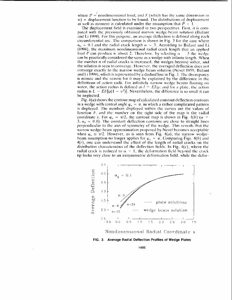
The displacement field is examined in two perspectives. First. it is compared with the previously obtained n;lITOW wedge-beam solution (Bazant and Li 1(94). For this purpose, an average deflection is defined along each circumferential arc. The comparison is shown in Fig. 3 for the case where a o = 0.1 and the radial crack length (~ = 3. According to Bazant and Li (1994), the maximum nonJimcnsional radial crack length that an applied load I' can produCl.: is about 2. Thcrdorc, by sl'lecting H 3 thl' wl'dgl' can be practically considered the same as a wedge with infinite length. When the number n of radial cracks is increased, the wedges become softer, and the solution is seen to converge. However, the averaged deflection docs not converge exactly to the narrow wedge beam solution (Nevel 1959; BaZant and Li 1(94), which is represented by a dashed line in Fig. 3. The discrepancy is minute and the reason for it may he explained by the difference in the definitions of action radii. For infinitely narrow wedge beams floating on water, the action radius is defined as I = EIIJJ; and for a plate, the action radius is L = EII[JJ(I - v 2)J. Nevertheless, the difference is so small it can be neglected.
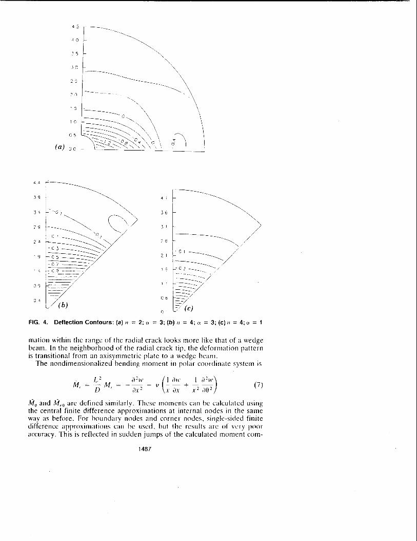
Fig. 4(a) shows the contour map of calculated constant deflection contours in a wedge with central angle '+'11 = 7T. in which a rather complicated pattern is displayed. The numbers displayed within the curves are the values of function F, and the number on the right side of the map is the radial coordinate x. For '+'11 = 7T/2, the contour map is shown in Fig. 4(b) (a = 3; a" = 0.1). The constant deflection contours arc close to straight lines perpendicular to the axis of symmetry of the wedge. This reveals that the narrow wedge-beam approximation proposed by Nevel becomes acceptable when '+'" :'5 7T/2. However, as is seen from Fig. 4(a), the narrow wedgebeam assumption no longer applies for ,+,,, = 7T. Comparing Figs. 4(b) and 4(c), one can understand the effect of the length of radial cracks on the distribution characteristics of the deflection fields. In Fig. 4(c), where the radial crack is reduced to n -, I, the deformation field heyolld the crack tip looks very close to an axisYlllmetric deformation field, while the defor-
-0.5
c: 0 00 o 1 ......, °0 u Q) 0.5 -....... Q)
Q 1 0
Q)
Q.() 1.S ro plate solutions ~ n=6 Q)
> 20 n=12 wedge beam solution
< 25 ---L
-0 S 00 05 1 0 1 S 2 0 2 5 30 3 5
Nonel! rnenslOnai Rad la i Coord ina t.e x
FIG. 3. Average Radial Deflection Profiles of Wedge Plates
1486
(a)
4.4
39 4 ; ~--~~~ 34
-Ol~ \\)
35
2 9 3 1 / V ~~~~~ 2 5 ~ 24 ~ /
-01 / 1 9 05~' 2 1 ~/ =---------= ------- '/ 07 -
-:.~ 'Z.....::- ~-:.~~: -=--~, / ./ 1 5 - 0 J _________ --------------- / 1 " -. /
P /
~/ 09 11
~ ----06 -04 ( b) >..7 (c)
01
FIG. 4. Deflection Contours: (a) II = 2; a = 3; (b) II = 4; a = 3; (c) II = 4; a = 1
mation within the range of the radial crack looks more like that of a wedge beam. In the neighborhood of the radial crack tip, the deformation pattern is transitional from an axisymmetric plate to a wedge beam.
The nondimensionalized bending moment in polar coordinate system is
M =-M = ---v --+--_ L2. a2W (I rill' I i/ 211')
, [)' ax 2 x ax x 2 ao 2 (7)
Mo and M,o are defined similarly. These moments can be calculated using the central finite difference approximations at internal nodes in the same way as before. For boundary nodes and corner nodes, single-sided finite difference approximations can be used, but the results are of very poor accuracy. This is reflected in sudden jumps of the calculated moment COITI-
1487
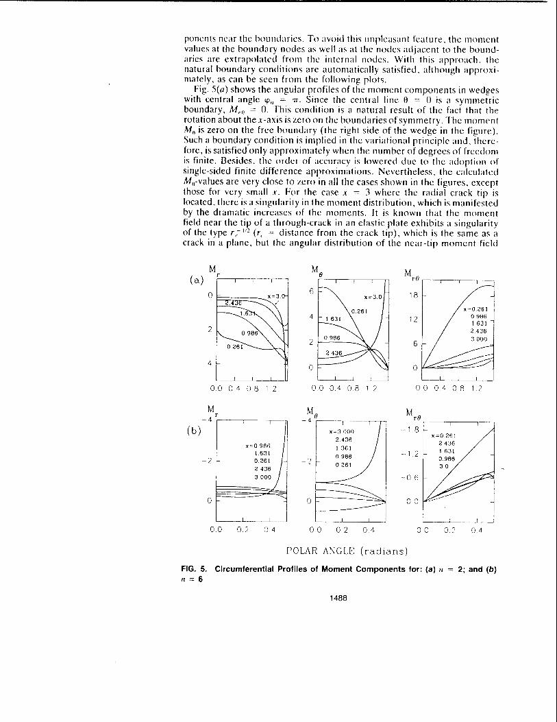
ponents ncar the boulld;lries. To avoid this unpleasant feature, the IllOlllent values at the boundary nodes as well as at the nodes adjacent to the boundaries are extrapolated from the internal nodes. With this approach, the natural boundary conditions are automatically satisfied, although approximately, as can be seen from the following plots.
Fig. 5(0) shows the angular profiles of the moment components in wedges with central angle \fl" = 'IT. Since the central line e = () is a symmetric boundary, M,o = O. This condition is a natural result of the fact that the rotation about the x-axis is zero on the boundaries of symmetry. The moment Mo is zero on the free boundary (the right side of the wedge in the figure). Such a boundary condition is implied in the variational principle and, therefore, is satisfied only approximately when the number of degrees of freedom is finIte. Besides. the order of accuracy is lowered due to the adoptioll of single-sided finite difference approximatiolls. Nevertheless, the calculated Mil-values are very close to zero in all the cases shown in the figures, except those for very small x. For the case x = 3 where the radial crack tip is located, there is a singularity in the moment distribution, which is manifested by the dramatic increases of the moments. It is known that the moment field ncar the tip of a through-crack in an elastic plate exhibits a singularity of the type r(~ 1/2 (r, = distance from the crack tip), which is the same as a crack in a plane, but the angular distribution of the near-tip moment field
M (a)
r
4
Me r----,---.------,,----Tl
6 x~3.0
4 1631
2 f-0_.9_86 __
2.436
o
18
12
x~0261
0986 1631 2.436
3 000
00 0.4 08 1 2 00 0.4 08 1 2
__ ~ __ .~L.._._
00040812
M r
~ 4 '---~--'~~'--r
(b) X~O 986
1631 ~ 1 2
0261)-2436
3000
~2
~O 6
o 00
___ LI ~~-'--_---'
00 02 o 4 00 02 o 4 00
POLAR ANGLE (radians)
x=0261 2436 I 631
0986
0.2
FIG. 5. Circumferential Profiles of Moment Components for: (a) /I
n = 6
1488
04
2; and (b)
is differcnt [sce William (1952) and Paris and Sih (1965)J. It can he shown that the presence of an elastic foundation cannot change the type of singularity. Fig. 5(h) shows the momcnt distributions for wedgc angle = Trio, which is typical of moment distributions for small wedge angles. The moments are nearly uniform, appearing almost as straight lines, which means the deformation field is essentially one-dimensional. It is interesting to note that the radial momcnt Mr is positivc in Fig. 5«(/), which means that the bottom face of the plate is undcr tension; however, for small wedge angles the radial moment becomes negative, which means the upper face is under tension, and the wedge behaves similarly to a cantilever.
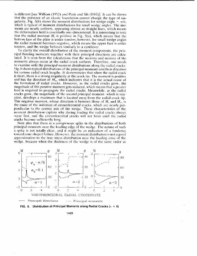
To clarify the overall distribution of the moment components. the principal bending moments together with their principal directions arc calculated. It is seen from the calculations that the maxima and minima of the moments always occur at the radial crack surfaces. Thereforc. one needs to examine only the principal moment distributions along the radial cracks. Fig. 6 shows typical distributions of the principal moments and their direction for various radial crack lengths. It demonstrates that when the radial crack is short, there is a strong singularity at the crack tip. The moment is positive and has the direction of Mil, which indicates that it is the actual cause of the formation of radial cracks. However, as the radial cracks grow, the magnitude of this positive moment gets reduced. which means that a greater load is rcquired to propagate the radial cracks. Meanwhilc, as the radial cracks grow, the magnitude of the second principal moment, which is negative, develops a maximum that is located away from the radial crack tip. This negative moment, whose direction is between those of M, and Mo. is the cause of the initiation of circumferential cracks, which are nearly perpendicular to the ccntral axis of the wedge. These characteristics of thc moment distribution explain why during loading the radial cracks always occur first, and the circumferential cracks will not form lIntil the radial cracks becomc sufficiently long.
Note also that there is a conspicuous spike in the distributions of both principal momcnts ncar thc loading edge of the wedge. The nature of sllch a spike is not totally clear, and it might be an indication of a tendency toward cone-shaped failure. Ilowever, the moment distribution is not a good approximation to the true strcss distribution lIear the loading zone of the wedge, because whcn the thickncss of the wedge is of the same order as
M e M e M e 6 .3 2 I ,---------- 90 ,------, 90 -- - - ... 90
2 , ,
4 rp =7T/6 ,
... - - J
n ... - " . ' 60 f./~ I 60 , 60
2
~ ~ ~ 0 .30 .30 0 .30 0
-1 0:=1 0: =2
-2 I I 0 -2 0 -1 0 0 2 4 0 2 4 0 2 4
NONDIMENSIONAL RADIAL COORDINATE
Principal directions . - - - Principal moments
FIG. 6. Distribution of Principal Moments along Radial Cracks (1/ = 6)
1489

the arc length of the loading edge, the three-dimensional effect must be very significant. making the plate-hending theory no longer suitablc. On the other hand, since the plate theory is, nevertheless, the first-order approximation, it is still reasonable to expect that the plate solution provides a correct qualitative, though not necessarily quantitative, estimate of the overall deformation.
ENERGY BALANCE EQUATION FOR RADIAL CRACK PROPAGATION
The basic idea of energy balance during radial crack propagation wa~ presented by Bazant and Li (1994), dealing with one-dimensional analysis. In the present case, the work done by the distributed load varies from point to point, because the deflections at the Il~ading edge of H1C wedges are not constant. However, the quantity that is of interest is not the distribution of the work, but rather the total work of the applied force. For this purpose, it is sufficient to use the averaged boundary deflection woo The averaged boundary deflection can also be written in the form IV" = PL 2f(a". a, 11)/ 2nD. where the function {(a". a, n) has the same dimension as 1\'. This quantity could further be made nondilllensional by comparing the deflection with L. The total work done by the applied load can then simply be written as Pw,,/2. The increment of this work due to a change in the radial crack length must be absorbed by the ice sheet to create new crack surfaces, therefore
(Xa ,/7)
The only difference between this equation and its one-dimensional counterpart given by Bazant and Li (1994) is that the function f now depends also on n. Function f, which is proportional to the compliance of the structure, is plotted in fig. 7(a) as it function of the radial crack length. The loading zone radius is fixed at no = (Ull. The compliance is seen to increase with increasing 11. For sufficiently large fI, the compliance or the wedge system approaches a cOllsta Ilt, which is ;dlllosl t he sa me as the cOlllplia lice for the wedge-beam approximation.
As is already known from the one-dimensional analyses, the compliance will reach a maximulll and then start to oscillate around this maxilllulll value for sufficiently long radial cracks. The slllallest radial crack length, at which
w u z ..,; :3 0.. :::E o U
w o ..,; n:: w > ..,;
(a)
2 0
15 1!~3
10 f . ao ~ 00\
o 5 L~l ___ L-.-L __ ....L
o 2 ] 4
RADIAL COORDINATE X
4.0
(b)---'~/l ] 5 -
1 ]0
5 o 0 0 6 1 2 1 8 2 d
WE:DGF: ANGLE (2rr/n)
FIG. 7. (a) Average Compliance; (b) Limiting Radial Crack Length
1490
the colTlrliance derivative is zero, will be called the lilllitll1g Icn!,-th of thc radial cracks. In one-dimensional analysis, the limiting length is a function of only af). In two-dimensional analysis, however. the limiting length depcnds also on IllFig. 7(h)J. The smaller the n, the longer the limiting length. When Il is large enough, the limiting length arproaches a constant (about 2.3) that is quite close to the wedge-heam solution (2.02). The causes for this difference are various. In addition to the inevitahle numerical error In the two-dimensional analysis, it may also he noted that the two-dimensional model is sofler than the wedge-heam Illodel, the lillliting Ienglh, therefore, should he longer than the wedge-he;lIl1 solution. Neverlheless, such a dilfcrenn: docs not seelll to be significant.
THEORY OF INITIAL CRACK SPACING
As noticed by Frankcnstein (1903), the number of radial cracks formed in a penetration test is a highly variable quantity. Howcver, for different sizes of the loading device, his tests demonstrated that the numher of radial cracks derends on the diameter of penetralor. It is therefore c1car that, despite inevitahle large random scatter of tests, thcre is still a deterministic trend. We will discuss this with the understanding that we are seeking only a qualitative theory that is capablc of cartming thc salient features.
As is well known, the linear elastic fracture mechanics cannot modcl directly the crack initiation, since when crack length is zero, the energy release rate is also zero. Thus using Griffith's equation of energy balance, the load required to initiate a crack is incorrectly predicted to be infinite. Therefore the strength concept must be used in some form. When the load is uniformly distributed over a circular area of radius (x", the axisymmetric plate equation can be solved analytically to determine the load Pr at which the first crack occurs (i.e., I, is reached)
nO'" I II 2 = I,ll 2
1'/ = J( 1 + l')kei'(a,,)' (,(O',,)
(see Ikrtz (IHH4), Uelllstein (llJ2lJ), and Wyman (llJ5())j. hll u" = O.()l, (J.06, 0.1, 0.3, OJ), and I; C(n,,} = 3.241, 2.129, I.HI2, 1 .IJ), O.72(), and 0.437. Note the assumption that there is a holc in the ice rlate is valid only for calculating the hehavior sufficicntly far away frolll the center. ;\s f;lr <IS
the stress in the center is concerned, this assumption is not aprropriate anymore.
When (9) becomes satisfied, the ice starts to form cracks. However. the strength theory alone cannot rrovide the numher of radial cracks. Therefore, the energy criterion must be used. First, recall that when the radial crack length approaches zero, so docs thc energy release rate; and when the radial crack length approaches its limiting length, the energy release rate is reduced to zero again. In other words, the crack propagation is unstable initially, hut will hecome stable when a is large enough. Therefore, once the radial cracks start growing, they will not stop until the energy release rate starts to decrease and the energy balance (H) becomes satisfied for I' = 1'(. Such an equation can be written in a nondimensional form as
whcre I"
11
1"(0',,, a, n)
L 3( I - v 2)
I" nC 2(0',,)
char;lcteristic size of the process 70ne of icc.
1491
(10)

For each given n (and 0:11 as well, of course), (10) makes it possible to determine the initial radial crack length 0., which will henceforth be denoted as 0.,. However, 0., is generally different for different 11. To determine 11 we need one more relation. The additional relation can be obtained by considering the finite energy release caused by a sudden crack length jump from zero to 0." which is accompanied by an increase of deflection under the constant load. It is convenient to consider complementary energy, and then this change of energy must be calculated at constant load. The energy released must be consumed by creating the crack surfaces, and so If( 0.11 , 0."
n) - f(o.ch 0. 0 , n)]PJL 2!4'lTD nLo.,hGr, or in the nondimensional form
n o.,n 3(1 - v") ~ 'lTC2(0.,,) /"
( 11 )
The average energy release equation [( 11)] and the energy release equation [(10)] can be simultaneously satisfied if and only if the function q is equal to f", which occurs when q reaches its maximum. Functions f" and q are plotted in Fig. 8 for different 11 and 0.0 = O. I. It can be seen that there is only one root in the entire range. The maximum of q is always smaller than the maximulll ofr.,. Denoting the maxilllulll value of q(O:f), 0:, n) as
1 2 W n = 2 09 E-< n = 4 n = 6 «: 0.4 c:t:
W 06 UJ «: w .....:J o 4 W f 03 c:t: a
°0 == 0.1 >-- q 0 00 00 00 c:t: W
00 0.3 0.6 09 00 03 06 09 00 03 06 09 Z W 1.5 -------
1 5 1.5 .....:J «: Z , 0 1.0 I 1.0 UJ
10
Z W ::::s 05 05 05 Cl Z n = 12 n = 24 0 Z 00 00 00
00 0.3 0.6 09 00 03 0.6 0.9 00 09
NONDIMENSJONAL RADIAL CRACK LENGTH
FIG. 8. Tangent Slope f, and Secant Slope q of Compliance ((Xo == 0.1)
TABLE 1. Function Q and /1/Q
a o n 2 3 4 5 6 8 12 24 36
(1.1 Q (l3.'iX (I.'iXO O.7.'i1 O.XHO () 97H 1.113 1.2.'i(, 1.397 1433
0.1 II/Q .'i . .'iH.'i 'i.17.'i 'i.325 .'i.6R2 h.135 7.IX6 9.553 17.IX 25.12
0.01 Q 0.339 0.569 0.741 OX67 0.%2 1.091 1.223 1.34R U7Y
0.01 II/Q 'i.X').\ 'i.271 SAOO 'i7(,7 6.2.1<, 1'1:\3 'J. 732 17.HO 2(1. II
1492

Q(O'o, n), which is listed in Table 1, we car rewrite the energy release rate equation I (10) 1 as
n L 3( I - v~) (12 )
Experiments (Frankenstein 1%3) showeu that n increases with increasing punch size, and this trend is indeed captured by (12): because 0'0 increases with punch size, whereas C(O'o) decreases with 0'0' the final result is an increase in the right-hand side of the equation, and thus an increase in n. More specifically, in Frankenstein's tests, 0'(1 = (J.()6 for the small punch size and 0'0 = 0.6 for the large punch size. The average number of the radial cracks for the small size punch is about 4.6, and for the large punch size about 24. The ratio 1/(0'0 = 0.6)/"(0:0 = (J.()6) is about 5.2. Now, neglecting the differences in L and I" for different test sites, we see from (12) that the ratio of the radial crack numbers should be approximately equal to the ratio of C(O.06)/C 2(O.6), which is about 8.7, times the ratio Q(O.6, 24)/Q(O.06, 5), which is roughly 1.6. Thus according to (12), the predicted ratio of the radial crack numbers is about 14. Considering the crudeness of the assumptions used in this calculation and the considerable random scatter exhibited by the test data, the predicted value docs not seem unreasonable.
The foregoing prediction might be improved by considering 10 , In the large-size tests, the ice plate was a combination of snow and clear ice, whereas in the small-size tests, the ice plate was clear ice. Because 10 is proportional to the maximum size of the inhomogeneities in the ice, and the inhomogeneities in the clear ice are finer than those in the snow ice, 10 for the mixed snow and clear ice must be larger than that for the clear ice. The prediction should be multiplied by the ratio of 10 (clear ice) over 10 (snow and clear ice), which should bring the predicted value closer to the measured value, 5.2.
It is also noted that the smallest value of the right-hand side of (12) is zero, while the left-hand side has a minimulll, denoted as U(OIl) , which is larger than zero and occurs at n = 3, as can be seen from Table I. Then, through (12), one can define the threshold length Lo as
( 13)
When the action length L is smaller than Lo , no radial cracks form during loading, and the only wayan ice plate may fail is by a conic crack under the load. For instance, for an ice sheet with I" = 0.2 m and 0 0 = O. I, Lo = 3.91 m. When h is measured in meters, the action distance L can be related to It as L = 1611"4
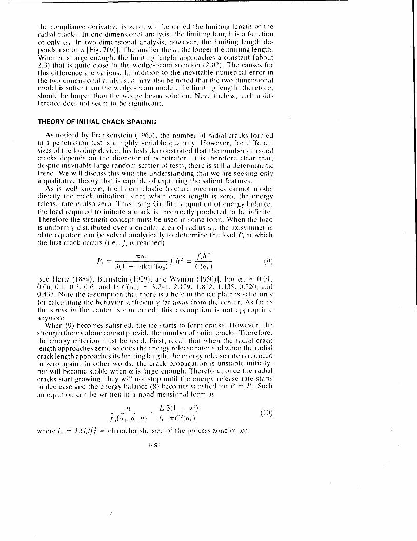
; thus Ito = 0.15 m. Note that the aforementioned threshold value is defined for constant 0 0 , J:t is easy to show that even at constant a(), there is still a lower limit for h I Fig. 9(a)]. because function C approaches infinity as a logarithmic function of h. The foregoing equation can also be used to define a lower limit for the punch radius ao under the condition of constant It, in which case Lo is given and the minimum 0 0 is to be found through (12) [Fig. 9(b)]. According to this theory, the larger the thickness It, the smaller the ao . Whether this is true should be confirmed by future experiments.
Eq. (12) can be used directly to find L, and thus also h, that corresponds to a given n. However, we are often interested in the reverse problem: to determine 11 for a given h. It is natural to expect that for an arbitrarily given
1493
f--- 2a -1 f1~
~1II~ punch cone
(a) a 0 constant (b) h constant
FIG. 9. Change of Failure Mechanism for: (a) Constant I/o; and (b) Constant"
II there might be no n that satisfies thc equation. because h is a continuous quantity whereas 1/ is no\. Physically. when there is no 1/ that can satisfy (12), which is an energy balance equation, some of the assumptions that lead to (12) must be invalid. Although it is assumed that the radial cracks are equally spaced and have equal length, in reality this might not be truc: the radial crack spacing and length might be uneven due to inevitable inhomogeneities in the ice. Although it is assumed that all potential energy is transferred into crack formation, in reality this becomes impossible if some of the energy is converted into kinetic energy during crack jumping. In other words. (12) gives only a simplified picture of a very complicated physical phenomenon. Therefore, whenever (12) cannot be satisfied, we simply pick, for a given It, a value n that makes the unbalance of (12) the smallest.
Nevertheless, some questions remain unsolved. Using the experimental data of Frankenstein. one can determine 10 indirectly thwugh (12). The results are II) = 0.2 m for clear ice and I" = 0.6 m for snow and clear ice. These values seem to be a magnitude too large. The problem may be related to one of our basic hypotheses. which assumes the radial craek to be totally open during loading. According to Frankenstein (\963). the radial cracks are always closed at the top surface of the ice plate, and the crack surface will not open until the applied load is removed. However. detailed consideration would require a three-dimensional analysis. which is beyond thc scope of this paper. Once suitable test data become available, this question should be studied further.
The argument that led to (\2) for determining the angular crack spacing represents a refinement and extension of the approximate argument used by Bazant and Ohtsubo (1979) to determine the initial spacing of the parallel cooling cracks in a half-plane [see also Bazant and Cedolin (1991), chapter 12].
SIZE EFFECT
Previous studies (Bazant 1991, 1992) yielded a result at first perplexing: for elastic plates of different thickness h, resting on a Winkler foundation. the nominal stress (J N = Pill 2 required to propagate geometrically similar
1494
U;ICb. is, according 10 U+M, pmporlionallo II I'" This SCCIllS to conflicl with the fact that in LEFM the size effect is of the type (fN~ (size) 112, and Iz is the only geometric dimcnsion (i.e. size) for the infinitc plate. The explanation is that the problcm is two-dimensional, and·size Iz is measureu in the third dimension; thus h represents merely a parameter, not an actllal dimension in the (x, y) domain in which the boundary-value problem is 11l;llhclll;ltic;dly defincd. Thc ch;lIactcristic dimcnsion in Ihc planc (x, v) is not geometric, but is provided by Land inueed, in terms of L Ihe LEFM size effect is of the type <TN ~ I" 1/2 (Bazant 1992; Bazant and Li 1992).
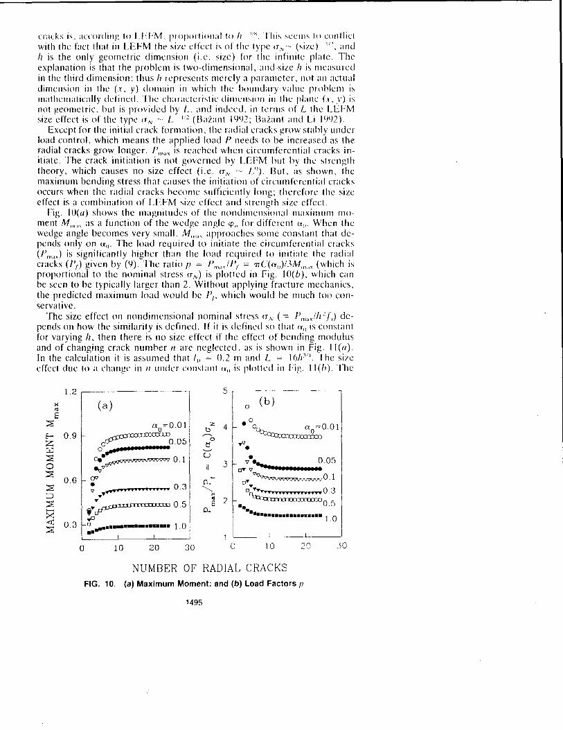
Except for the initial crack formation, the radial cracks grow stahly under load control, which means the applied load P needs to be increased as the radial cracks grow longer. P""" is reached when circumferential cracks initiate. The crack initiation is not governed by LEFM but by the strength theory, which causes no size effect (i.e. (TN ~ LII). But, as shown, the maximum bending stress that causes the initiation of circumferential cracks Occurs when the radial cracks become sufficiently long; therefore the size effect is a combination of LEFM size effect amI strength size effect.
Fig. 1O(1I) shows the magnitudes of the nondilllcnsional maximulll moment M",." as a fUllction of the wedge angle \PI/ for different (Xti. When the wedge angle becomes very small, M""" approaches some constant that depends only on (~tI. The load required 10 initiate the circumferential cracks (P",,,,) is significantly higher than the load required to initiate the radial cracks (P,) given by (9). The ratio fJ = P", .• ,IP, = TIC«(XtI)/3M",,,, (which is proportional to the nominal stress UN) is plotted in Fig. IO(b), which can be seen to be typically larger than 2. Without applying fracture mechanics, the predicted maximum load would be I'" which would be much too conservative.
The size effect on nondimensional nominal stress (T/v (= P"''')'' 2 If) depends on how the similarity is defined. If it is defined so that (XII is constant for varying II, then there is no size effect if the effect of bending modulus and of changing crack number n arc neglected, as is shown in Fig. II(a). In the calculation it is assumed that /tl = 0.2 m and L = 16hl/~. The size crrect due to a change in 11 under constant (Vii is plotted in rig. 11(/1). The
1.2 5
>< (a) 0 (b)
'" E .0 ~ °0=001 z 4 b O~llll~g~)O.Ol E-< 0.9 ~IIIcJ)IIIn ,..-...
0 Z o 0.05 ~ .. " w 0 ................. '-" • ~ • u • Oil ~vvvwvvvvvw O. 1 3 ". 0.05 0 e.;," II d'Y " ................. ~ CP .,. 'V~'Vw~'VQ'V'V'V'V"\l7'V O. 1 0 6 • P-. 0 ~ 0 3 "-...... •
" .................. or{;;;;;;;;;. ......... 0 . 3 ~ ... >< .. 2 ~ ""r, .. !! •• '··l.l!! 0.5 E "'11""0 5
P-. .. . ....... •• >< ..·················1.0 <t; .,0
0.3 o ................... 1.0 ~ .... 1
0 10 20 30 0 10 20 30
NUMBER OF RADIAL CRACKS FIG. 10. (a) Maximum Moment: and (b) Load Factors f!
1495

- -------.. -~~-~- 0.4 ~~--~-~
0.9 (a) 0:
0=0 1 n varies
0:0=0 1
o 6 n=3 0.3
n=6 ~l 0.3 n=12 0:
0=005
~ o 2
~2 0 2 ~2 0 2
Z b
'---" 1 2 c: (c) (d) a o= 1m n varies 09
09
n=3 06 a o=0.5m
06 1.0m
1 5m n=6
0.3 0.3 n= 12
_L ___ L. __ L __ ~ __ . _ __L ___ ·_
~2 0 2 ~2 0 2
In(h) (h in meters)
FIG. 11. Size Effect for: (a) Constant 0:0 and Constant 11; (b) Constant 0:0 and Varying 1/; (c) Constant (/0 and Constant 11; (d) Constant (/0 and Varying II
left end of the curves corresponds to the threshold value Lo as discussed in the previous section.
It may be emphasized that the size effect due to a change in 11 can be seen only through a two-dimensional analysis. The conclusions in the previous one-dimensional study (Bazant ami Li IYl)4) could not reflect sllch a size effect. be.:ause in the narrow wedge-beam solution the maximum bending moment is independent of the wedge angle, and thus independent of 11.
When the ratio {lo/II is kept constant for various h, a reversed size effect is superimposed on the size effect just mentioned. Since 0.0 = (aolh)[11( I -v2)/EI'/4, 0.0 actually increases with h, and we know that when 0.0 increases, ~ the maximum value of the nominal stress increases, and thus the size effect gets reversed: the larger Iz is, the larger (TN is. However, since the dependence of a" on h is very weak in the normal range of thickness, such a reversed size effect can often be neglected. Actually, keeping Go constant for all h is the case that is more relevant to the practical problem-an aircraft of a fixed and known contact area landing safely on the ice plate, or a submarine of a fixed and known contact area of its sail penetrating upward through the ice. For this case, 0.0 decreases with It, and so the maximulll nominal stress decreases with It too, as is shown in Fig. 11 (c) for several chosen n. This type of size effect has already been discussed by Bazant and Li (1994).
1496

It is interesting to note that even wIth constant (III, 1/ still increases with /z, because the rate of increase of L is faster than that of function ('2. Thus the overall effect of changing 11 is to enhance the size effect under the condition of constant (I", as can he seen from Fig. II(d).
CONCLUSIONS
1. The variational finite difference method, in which the equilibrium equations for nodal deflections are obtained by differentiating the potential energy approximated by finite differences, is an effective way to solve an elastic plate on elastic foundation. The energy release rate is obtained by differentiating the potential energy as a function of the radial crack length.
2. Based on the assumptions of linear clastic fracture mechanics and the plate bending theory, our numerical calculations confirm that the load from the penetrating object (a punch) distributed along a small (but not too small) circle causes propagation of radial cracks, and that the maximum load is reached at the initiation of circumferential cracks whose radial distance is less than the radial crack length. Assuming equal central angles of the radial cracks, one needs to analyze only one-half of an infinite wedge plate between two radial crack lines.
3. Although, as determincd previously, the nominal stress (load divided by plate thickness square) required to propagate geomctrically similar cracks is proportional to (thickness)'/x, the size effect is modified because: (I) Thc initiation of the circumferential cracks is governcd by the strength limit of ice rathcr than its fracture energy: and (2) the number of raclial cracks varics with the ice-plate thickness.
4. The previously prescnted simplified one-dimensional solution, in which the radial cracks are considered very dense and the wedge plates are treated as narrow wedge beams (Nevel's approximation), is sufficiently accurate for wedge angles up to 1T/4. The error is negligible when the wedgc angle is less than 1T/6. However, the complicated distribution of the moments can only be obtained through a two-dimensional analysis.
5. As an extention and generalization of a previous idea, a theory for the initial crack spacing is proposed. The idea is that the initial crack number n must satisfy the following three conditions simultaneously: (I) The energy release rate is equal to the fracture energy of the icc; (2) the (otal energy released suffices to produce the total crack area nihil; and (3) the applied load is such that the maximum stress before cracking be equal to the tensile strength of the icc. This thcory also revcals that for a given nontiimensional punch radius a() == anlL (Of) = radius of punch size; L = decay length of the plate), there is a threshold thickness below which the icc plate fails by a conic crack. The smaller the at" the larger the threshold thickness.
6. Aside from the size effect on the modulus of rupture for bending, there are two factors that affect the final combined size effect: (I) A change in the number n of radial cracks as a function of af} and L: and (2) the modification of sizc effect due to the definition of similarity. If constant n tl
is used to define the similarity, and as long as 11 is constant, there is no size effect due to a change in thickness. If {III is constant, then there is a size effect because a tl decreases with thickness. The effect of a change in the number of radial cracks is always to enhance the overall size effect.
1497

ACKNOWLEDGMENT
Financial support under grant NO()OI4-91-J-l109 (monitored by Dr. Y. Rajapakse) from the Office of Naval Research to Northwestern University is gratefully acknowledged.
APPENDIX. REFERENCES
Baz,lIlt, Z. P .. Ohtsuho, R .. allll Aoh, K. (1l)7l)). "Stability ,1Ild post-critical growth of a system of cooling and shrinkage cracks." 1111 . .I. Fracture. Vol. 1'1, 443~4'i()
Bazant, Z. P .. and Cedolin, L. ( Il)l) I). Sil/hilily oIslrllclurcs. cla,llie, iIlCIl/,llie. /"IIc!II/(' alld damage Ih('orics. Oxford University Press, New York. N. Y.
Bazant, Z. P. (1991). "Large scale thermal hending fracture of sea ice plate." ReI)' 91-314021. Dept. of Civ. Engrg .. Northwestern University. Evanston. Ill.
Bazant, Z. P. (191)2). "Lnge-scalc fracture of sea ice plates." I 'roc. , 11111 fA III? 1111.
Ice SYlIlp .. IAHR, Banff. Alberta, Canada, l)9[-I()O'i. Bazant. Z. P., and Li, Y. N. (1994). "Penetration fracture of sea icc plate: simplified
analysis and size effect.".I. Engrg. Me(k. ASCE. I 2()(1l) , 1'121-1'142. Bernstein, S. (1929). The raihmj' ice crossing. Trudy Nauchno-Technicheskogo Kom
iteta Narodnogo Komissariata Putei, Soobshchenniia, Russia, Vol. il4 (in Russian). Bushnell, D. (1973). "Finite-difference energy models versus finite-element models:
two variational approaches on one computer program." NIIlIlcrical alld COlllfJlIlcr melhods in Slrtlclural IIIcchanics. Fenves et aI., eds .. Academic Press. New York. N.Y., 2!)2~336.
Forsythe, G. E., and Wason, W, R. (196()). Finill' diI/i'rence lIIelhods for l)(Irlilll dillerenlial eqllalions. Wiley. New York. N. Y.
Frankenstein, E. G. (1963). "Load test data for lake ice shee!." Tech. Rep. HI), LJ .S. Army Cold Regiom Research and Engineering Lahoratory, Hanover, N. H.
Hall, C. A., and Porsching, T. A. (I 99() Nllll1crical allalvsil ofparlial dillerl'lIlilll equa/iolls. Prentice-Hall. Inc .. Englewood Cliffs. N.J,
Hertz, H. (IilR4). "Ober das gleichgewicht schwillll1lender elastischer Platten [on the equilihrium of floating elastic rlates]." Wicdemallll.s;1l1l1alelldefl.hy.\..lIl1d Chon., Germany. Vol. 22 (in German).
Kerr, A. D. (197'1). "The bearing caracity of floating ice plates subjected to static or quasi-static loads-a critical survey." Res. Rep. 333, U.S. Army Cold Regions Research and Engineering Lahoratory, Hanover. N.H.
Nevel, D. E. (19SR). "The theory of narrow infinite wedge on an clastic foundatioll." TraIlS., Engineering Institute of Canada, 2(3).
Nevel, D. (1965). "A semi-infinite plate on an elastic found<ltion." US;1 ;1RRI~L Res. Rep. /3(; AD (jf6313, ARREL.
Paris, P .. and Sih, G. C. ([1J6'i). "Stress analysis of cracks." Fmcilire TOllghlll'Sl (/1/(/
lis Applicaliolls; STl' No. 381, ASTM. Philadelphia, Pa .. 3(). Selv<ldurai, A. P. S. (1979). Elallic analysis oI soi/-/ouw/alio/1 imeraClioll. Elsevier
Scientific Puh!. Co .. New York. NY. Westergaard. H. M. (192.1). "Om beregning af plader paa elastisk underlag Illcd
saerligt henblik pa<l sporgsl11aalct Olll spaendinger i betollvcje." Illgclliofen. Copenhagen, Denmark, No. 42 (in Danish).
Williams. M. L. (19'12). "Surface stress singularities resulting from various houndary conditions in angular corncr~ of plates under hending." I'roc .. III US No/. COIl
gfess oI Appl. Mc(k, 32'1. Wyman, M. (1950). "Dellections of an infinite plate." Call . .I. of Rcs .. Vol. A2X.
1498