pellet boiler - spishop
TRANSCRIPT

Pellet boiler
ThermoFLUX d.o.o. Bage 3, 70101 Jajce,
Bosnia and Herzegovina Tel/fax:+387-30–657-100
www.thermoflux.ba; [email protected]

2

3
Dear users,
Congratulations on choosing a boiler from ThermoFLUX d.o.o.
Please note that all persons handling this boiler thoroughly inspect and observe the operating and safety instructions. Always keep the instructions in place near the boiler.
Due to constant improvement and development of our products some pictures or illustrations in this guide may vary.
Important information:
The first commissioning and training of the user must be done by a servicer authorized by ThermoFLUX d.o.o or the importer, otherwise the
guarantee will not be valid.
4
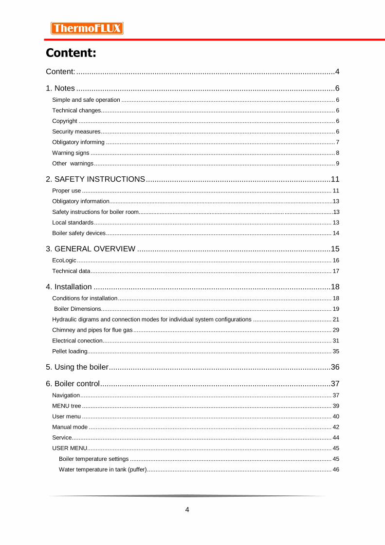
Content:
Content: ....................................................................................................................... 4
1. Notes ....................................................................................................................... 6
Simple and safe operation ............................................................................................................................. 6
Technical changes......................................................................................................................................... 6
Copyright ...................................................................................................................................................... 6
Security measures ......................................................................................................................................... 6
Obligatory informing ...................................................................................................................................... 7
Warning signs ............................................................................................................................................... 8
Other warnings ............................................................................................................................................. 9
2. SAFETY INSTRUCTIONS ..................................................................................... 11
Proper use .................................................................................................................................................. 11
Obligatory information..........................................................................................................................................13
Safety instructions for boiler room.......................................................................................... ..............................13
Local standards ........................................................................................................................................... 13
Boiler safety devices .................................................................................................................................... 14
3. GENERAL OVERVIEW ......................................................................................... 15
EcoLogic ..................................................................................................................................................... 16
Technical data ............................................................................................................................................. 17
4. Installation ............................................................................................................. 18
Conditions for installation ............................................................................................................................. 18
Boiler Dimensions....................................................................................................................................... 19
Hydraulic digrams and connection modes for individual system configurations .............................................. 21
Chimney and pipes for flue gas .................................................................................................................... 29
Electrical conection ...................................................................................................................................... 31
Pellet loading............................................................................................................................................... 35
5. Using the boiler ...................................................................................................... 36
6. Boiler control .......................................................................................................... 37
Navigation ................................................................................................................................................... 37
MENU tree .................................................................................................................................................. 39
User menu .................................................................................................................................................. 40
Manual mode .............................................................................................................................................. 42
Service ........................................................................................................................................................ 44
USER MENU............................................................................................................................................... 45
Boiler temperature settings ...................................................................................................................... 45
Water temperature in tank (puffer) ............................................................................................................ 46

5
Sanitary water temperature (HWS temperature) ....................................................................................... 48
Heating circuit ......................................................................................................................................... 48
WLAN modul* .......................................................................................................................................... 51
Language ................................................................................................................................................ 51
CHRONO PROGRAM ............................................................................................................................. 51
Info display .................................................................................................................................................. 54
7. TROUBLESHOOTING ........................................................................................... 55
8. START- UP ............................................................................................................ 58
Ignition - starting ...................................................................................................................................... 58
Boiler shutdown – switch off ..................................................................................................................... 59
Auto-adjusting power operation and extinguishing .................................................................................... 59
Automatic cleaning .................................................................................................................................. 59
Re-ignition ............................................................................................................................................... 59
9. CLEANING AND MAINTENANCE ......................................................................... 60
Regular cleaning of boiler EcoLogic ............................................................................................................. 60
Periodic cleaning of EcoLogic ...................................................................................................................... 63
10. Operation problems ............................................................................................. 67
11. Instructions on boiler recycling and proper disposal..............................................68
12. Guarantee............................................................................................................69
Manufactor contact..............................................................................................................................................69

6
1. NOTES
Simple and safe operation
This manual is an integral part of the boiler and contains important information for proper and safe operation of the EcoLogic boiler. Following the instructions in this manual, the boiler will work properly and you will avoid the danger, the costs of repairing failures, and at the same time the lifetime of the boiler continues. Everybody who operates the boiler operation must apply this instruction.
During the operation of the device, energy that heats the surfaces, doors, handles and flue pipes is released. Avoid contact with these elements without proper protective clothing (gloves). Make sure that children are aware of these hazards and keep them away from the stove during her work.
Technical changes
ThermoFLUX d.o.o. is constantly developing and improvng its boilers. The information in this manual is accurate at the time it is printed.
All the details in this guide on standards and regulations should be checked and compared with the nstalled boiler before using it.
We reserve the right to make any change that may result in deviation from the technical details and illustrations shown in this manual.
Copyright
It is forbidden to copy and download the content from this manual!
Written permission by ThermoFLUX d.o.o. is required before any copying or any storage in data transmission systems electronically, mechanically or in any other way, as well as copying and publication of parts or the entire instruction.
Security measures
Boilers are designed and manufactured in accordance with all legally prescribed standards and norms The boiler consists of several parts that are under a constant voltage of 230 V ~ AC. It is forbidden to perform any interventions and repairs during operation of the boiler. All interventions of assembling, replaceing and repairing must only be performed by qualified and licensed persons. Changes on security devices or electronic regulation are prohibited. Never pull out electrical cables coming out of the boiler, separate or bend them, even when it is disconnected from the network.
Avoid closing or reducing the dimensions of the ventilation holes of the room in which the device is installed.

7
Standards:
• UNI EN 303-5 Boilers for heating. Boilers for solid fuels, with manual and automatic power supply, with nominal heat output up to 500 kW
Directives:
• 2006/42 / EC: Directive MD • 2014/30 / EU: EMCDDA • 2014/35 / EU: LVD Directive • 2011/65 / EU: RoHS Directive 2 "
Obligatory informing
Everyone who operates with the boiler must read the instructions before using it, in particular, the chapter "Safety Instructions".
This applies especially to persons who occasionally work on a boiler, for example, cleaning and maintenance of the boiler. This instruction manual should always be kept near the installed boiler.
Children aged 8 and over, persons with reduced physical, motor or mental capacity, persons with insufficient experience and training, may use a device of this kind if they have been provided with supervision or have been given instructions regarding the safe use of the device and have been presented the dangers arising from it. Children should not play with such devices. The devices must not be cleaned or maintained by children without proper supervision.
The boiler room must be made according to regulations specifically related to fire protection. In the boiler room, no flammable materials, cleaning agents can't be stored.
Extreme cold can cause malfunction and unexpected behavior of electronic components.
After you unpack the boiler and remove the packing, make sure that the contents are complete. In case something is missing or damaged during transportation, contact the dealer where you purchased the boiler.
All electrical components of the product that guarantee the correct operation must be replaced with the original parts.
Before signing the warranty and leaving the boiler, the service technician authorized for the first commissioning must control the functioning of the boiler during the full working cycle. General cleaning must be done at least once a year.
8
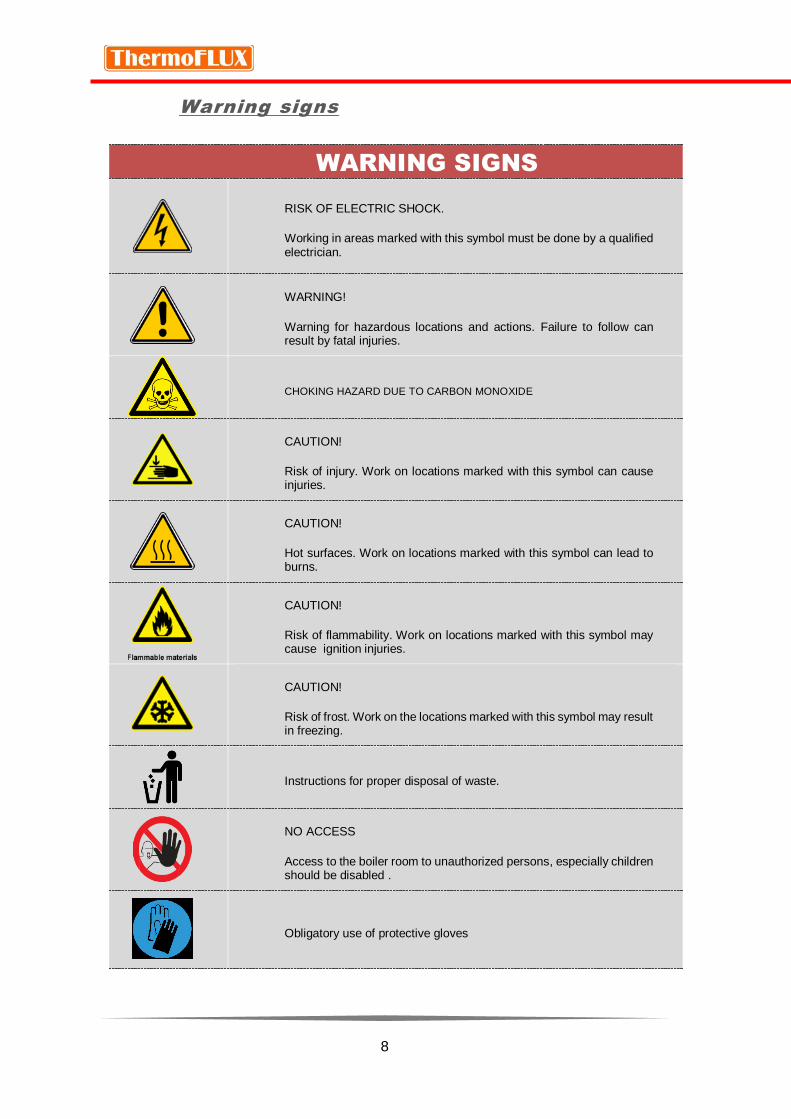
Warning signs
WARNING SIGNS
RISK OF ELECTRIC SHOCK.
Working in areas marked with this symbol must be done by a qualified electrician.
WARNING!
Warning for hazardous locations and actions. Failure to follow can result by fatal injuries.
CHOKING HAZARD DUE TO CARBON MONOXIDE
CAUTION!
Risk of injury. Work on locations marked with this symbol can cause injuries.
CAUTION!
Hot surfaces. Work on locations marked with this symbol can lead to burns.
CAUTION!
Risk of flammability. Work on locations marked with this symbol may cause ignition injuries.
CAUTION!
Risk of frost. Work on the locations marked with this symbol may result in freezing.
Instructions for proper disposal of waste.
NO ACCESS
Access to the boiler room to unauthorized persons, especially children should be disabled .
Obligatory use of protective gloves

9
Other warnings
WARNING
Do not open the door for ash cleaning during operation
Opening the door on the boiler during operation may cause the termination of boiler operation, injury, damage and leakage of flue gases.
The door open only during regular cleaning and maintenance.
WARNING
Never touch hot surfaces!
The hot parts of the boiler, flue gas pipes and heating pipes can cause severe burns!
Use gloves when working with the boiler.
Maintain the boiler only according to the instructions.
Insulate the flue pipes and avoid possible contact
WARNING
NEVER SWITCH OFF THE BOILER FROM ELECTRIC NETWORK DURING OPERATION
BOILER
Connection to the power should be with a permanent connection to avoid the possibility of the accidental shutdown
Although the boiler is secured with several levels of protection, forced power shutdown can cause unplanned failures.
10
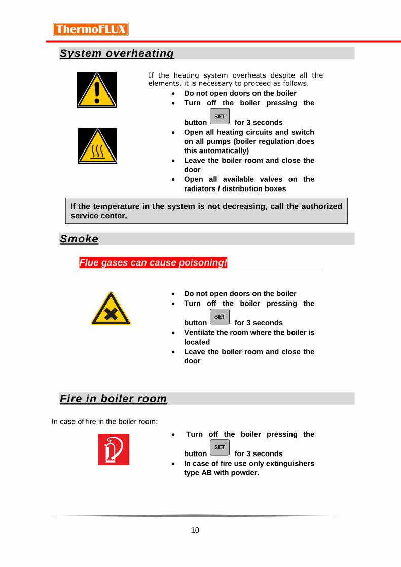
System overheating
If the heating system overheats despite all the elements, it is necessary to proceed as follows.
Do not open doors on the boiler
Turn off the boiler pressing the
button for 3 seconds
Open all heating circuits and switch
on all pumps (boiler regulation does
this automatically)
Leave the boiler room and close the
door
Open all available valves on the
radiators / distribution boxes
If the temperature in the system is not decreasing, call the authorized
service center.
Smoke
Flue gases can cause poisoning!
Do not open doors on the boiler
Turn off the boiler pressing the
button for 3 seconds
Ventilate the room where the boiler is
located
Leave the boiler room and close the
door
Fire in boiler room
In case of fire in the boiler room:
Turn off the boiler pressing the
button for 3 seconds
In case of fire use only extinguishers
type AB with powder.

11
2. SAFETY INSTRUCTIONS
Proper use
Basic principles
The EcoLogic boiler has been designed and tested in accordance with the safety regulations deriving from the EN 303-5: 2012 directive. However, improper use of the boiler can result in bodily injuries that can ultimately result in the death of users and / or third parties as well as damages to the boiler itself or other material assets.
Handling the boiler
The boiler can only be used when it is in its proper condition. Use the boiler in the manner described in this manual. Get informed with security measures and possible dangers. Remove all faults and malfunctions that could affect your safety.
Using the boiler
The boiler is intended for combustion of wood pellets. Any other use is improper. The manufacturer will not be held responsible for any damage caused by improper handling. Proper use implies maintenance of the installed boiler, operation and maintenance conditions prescribed by the manufacturer.
The user can enter or change only those values that are specified in this manual. Any other parameter value will affect the control program and boiler operation, which can ultimately lead to a break or improper operation.
Changes on the boiler
It is forbidden to make any changes on the boiler or equipment supplied. It is forbidden to deactivate the security functions. The manufacturer will not give any warranty if the user or a third party performs an unauthorized intervention on the boiler and equipment that comes with it.
The boiler may only be used for the purpose for which it is produced. The manufacturer does not accept any responsibility for damage caused to persons, animals or property resulting from faults in installation, incorrect regulation and maintenance or improper use of
the boiler.

12
Pellets that can be used in boilers
The boiler is designed exclusively for burning wood pellets with a
diameter of 6 mm and a length of 10-30 mm.
What is pellet
Pellet is obtained from wood, if it is possible, from the core of the trunk with the lowest proportion of bark. The bark contains the most moisture, dust and impurities that wood gets during growth, therefore has a lower caloric value than the core, and another problem is that it leaves the sediment when burning. Ideal wood for pellet production is one that does not burn too long or too short and creates a long-lasting glow. Pellets are made from sawdust waste (typically in a ratio of 20-40% softwood + 60-80% hardwood), in special machine under high pressure which leads to thickening. It is not allowed to use any additives or glue during the pellet. production The pellet contains a minimal amount of moisture and ash, and has a maximum energy value for the type of wood from which they are produced.
Recommended wood pellets and standards
Pellets quality arises from Standard pellets C1 to EN 303-5: 2012 Table 7; Water content less than 12% according to DIN 51731 - HP 5, DINplus certification program and ÖNORM M 7135 - HP 1 or EN PLUS - UNI EN 14961 - 2 (UNI EN ISO 17225-2) class A1 or A2, 6 mm diameter, length 10-30 mm.
Particular attention should be paid to the quality of wood pellets. Low-
grade pellets can cause malfunction of the boiler.

13
Unallowed fuels
The pellets not consisting the standards mentioned in this manual is not allowed to burn in a boiler. Using a bad quality pellet or any other material can lead to damaging your boiler's important functions and may result in the termination of the warranty and associated liability.
Obligatory information
All persons managing the boiler must read the manual before starting
to use it and in particular the "Safety instructions".
This applies especially to persons who occasionally work on a boiler,
e.g. cleaning and maintaining boilers.
This instruction should always be kept near the installed boiler.
Children aged 8 and over, persons with reduced physical, motor or mental capacity, persons with insufficient experience and training, may use a device of this kind if they have been provided with supervision or have been given instructions regarding the safe use of the device and have been presented the dangers arising from it. Children should not play with such devices. The devices must not be cleaned or maintained by children without proper supervision.
Local standards
All local laws must be respected during installation, as well as standards and norms that are in force in the country where the boiler is installed even though
it is not listed in this manual.
During the first installation of the boiler or in the event of changes on central heating system, it is necessary to inform the competent authority in charge for control, and provide all the necessary permits.
Safety instructions for boiler room
The boiler room must be made according to current regulations, especially regarding fire protection. Storage of flammable materials, cleaning agents and similar materials must not be stored in the boiler room
14
The room where the boiler is installed must be frost-resistant
The boiler must not be exposed to colds or freezing temperatures. Extreme cold can cause malfunction and unexpected behavior of electronic components.
Fresh air supply
For combustion of pellets and normal work boiler needs fresh air. The room in which the boiler is installed must have an opening for fresh air supply. The recommended minimum dimension is 30x15 cm.
Boiler safety devices
The boiler is equipped with safety systems which, in the case of unforeseen situations, serve to stop the power supply and thus stop
the boiler operation.
Microprocessor control on the boiler: intervenes directly, turns off the boiler until
it cools down and shows an error on the display screen in case of a failure of flue gas fan, malfunction of the dispenser engine, failure of the ignition.
Fuse: Quick fuse, protects the boiler of large current drops and short circuit inside the boiler.
Safety Thermo Switch (STB): If boiler overheats (at 90 ° C), all pumps in the system turn on, attempting to cool the boiler. If this fails and the temperature continues to increase, the STB intervenes by sending the signal to the regulation, ERROR BOILER OVERHEAT and STB ACTIVATED are displayed and the boiler stops working. After the boiler is cooled, it is necessary to manually reset the switch and start the boiler.
Safety switches – in case the door is not closed, the grate in the burner does not
return to its original position, an error is shown on the display and the boiler stops working.

15
Boiler parts:
1. Burning chamber
2. Automatic grate 3. Ashtrays 4. Automatic
cleaning system of the tube heat exchanger
5. Tube heat
exchanger
3. GENERAL OVERVIEW
EcoLogic boiler is a high-class boiler, in the range of the best boilers at the European market.
The boiler control supports the connection of up to three circulation pumps, mixing valve motor, hot water storage tank and sanitary water boiler.
An optional modem for Internet connection can be ordered as an accessory. The user can have full control of the boiler via the application (to enable/disable, change power, temperature or program it).
Cross section of the boiler
1
5
4
2
3

16
EcoLogic
Identification and serial number
The technical data label and the serial number are located on the back of the boiler.

17
Technical data
EcoLogic 25
EcoLogic 35
EcoLogic 44
EcoLogic 55
Performance (measured according to EN 303-5: 2012)
Maximum power kW 25 35 44 55
Minimum power kW 8 11 13 17
Electrical conection V,Hz 230 V, 50 Hz 230 V, 50 Hz 230 V, 50 Hz 230 V, 50 Hz
Electrical conection (current) A 10 10 10 10
Boiler class 5 5 5 5
General information
Max. Permited presure bar 2,5 2,5 2,5 2,5
Max. Permited temperature °C 85 85 85 85
Min. permited return temperature °C 55 55 55 55
Fuel EN PLUS - UNI EN 14961 - 2 (UNI EN ISO 17225-2) Class A1 / A2
Pellet consumption min / max kg 1,7 / 5,4 2,4 / 7,5 3 / 9,5 3,9 / 11,9
Pellet silo capacity kg 170 170 170 200
Fresh air opening cm 30x15 30x15 30x15 30x15
Technical data
Boiler width with pellet silo mm 1050 1050 1050 1050
Height mm 1270 1460 1460 1650
Depth mm 1100 1100 1100 1100
Water content l 55 68 90 115
Weight kg 370 395 415 455
Height out / return mm 1125 / 603 1315 / 603 1315 / 685 1505 / 685
Chimney underpresure Pa / mbar
5 / 0,05 5 / 0,05 5 / 0,05 5 / 0,05
Flue gas pipe height (direction UP) mm 1250 1440 1440 1630
Flue gas pipe diameter Ø 130 130 130 130
* minimal power - 30 % maximum power
18
4. INSTALLATION
The commissioning of the system must be carried out by the personnel
authorized by ThermoFLUX d.o.o or the importer.
The warranty will not be valid if the boiler has not been commissioned
by an authorized servicer.
The first start-up includes the basic operation and maintenance of the boiler. The service technician authorized for the first commissioning must check the functioning of the boile at least during one complete work cycle. In some countries, it is obligatoy for first commissioning to be controled and autorizied by chimney sweep or a person authorized to control.
Risk of material and physical damage due to improper commissioning. If the first start-up is done by an unprofessional person, damage to the boiler and the heating system may occur.
Conditions for installation
The following conditions must be completed before the system is
released.
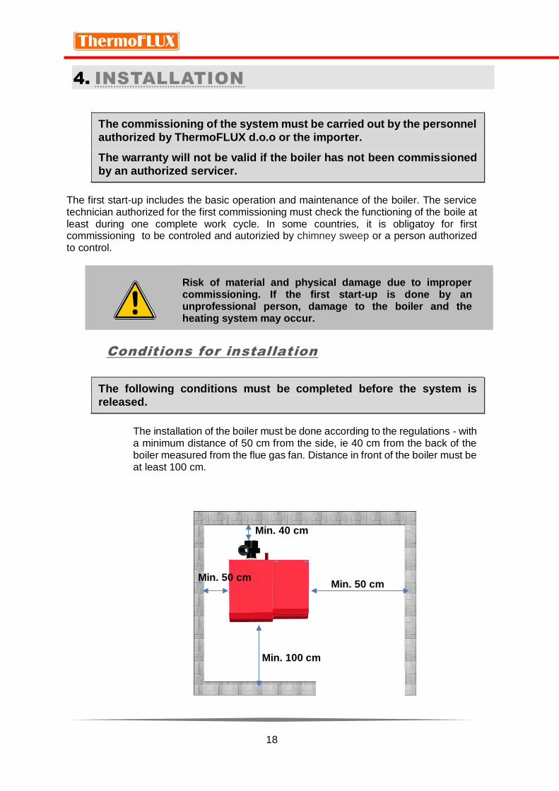
The installation of the boiler must be done according to the regulations - with a minimum distance of 50 cm from the side, ie 40 cm from the back of the boiler measured from the flue gas fan. Distance in front of the boiler must be at least 100 cm.
Min. 40 cm
Min. 50 cm Min. 50 cm
Min. 100 cm

19
Boiler dimensions
EcoLogic
25 EcoLogic
35 EcoLogic
44 EcoLogic
55
A Height 1270 1460 1460 1650
B Width 1050 1050 1050 1050
C Height of the flue outlet 1250 1440 1440 1630
D Depth 1100 1100 1100 1100
E Drain outlet 505 505 505 505
F Return connection height 603 603 603 603
G Output connection heght 1125 1315 1315 1505
Switch off main power supply
Be sure to turn off the main power before any work!
Check mechanical connections
• Check that all components are properly connected.
• Check that all mechanical components are securely attached.

20
Check hydraulic conections
Check that the circulation pump and the mixing valve are properly connected.
Check that the safety equipment is properly connected
After completing the work, fill the system and wait an hour to
control all connections.
The boiler can be connected to an open or closed heating system.
With the connection to the open heating system, the open expansion vessel must be at a height of 50 cm above the highest heating body and well insulated.
With the connection to the closed heating system, the safety valve and the membrane expansion vessel must be installed as close as possible to the boiler and there can't be any valves between them.

21
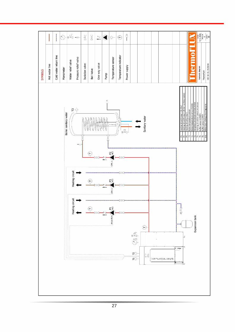
Hydraulic diagrams and connection modes for
individual system configurations
The boiler control supports the connection of three (3) circulation
pumps, mixing valve motor, buffer tank and sanitary water tank.
Only qualified service technicians have access to technical parameters and settings, and can adjust the hydraulic connection.
The operation system will be adjusted according to the conducted
installation.
Electronic regulation supports connection to three heating circuit pumps, ie outputs: P1, P2 and P3.
P1 pump output can be used for the heating circuit 1 or by activating
the buffer for that circuit
P2 pump output can be used for the heating circuit 2 or by activating
the sanitary boiler for that circuit
The pump output P3 can be used for the remaining heating circuit 3.
Motor mixing valve output can be used only for one heating circuit

22
Hydraulic conection diagrams

23

24

25

26
27

28

29
Chimney and pipes for flue gas
The boiler must be connected to the chimney. The chimney should be calculated and made according to EN 13384-1. The chimney must be
thermally insulated to prevent condensation.
Flue gas discharge must comply with applicable regulations as regards chimney dimensions and use of materials for its manufacture. The chimney must have an opening for cleaning the lower part.
The vacuum in the chimney should be at least 5 Pa and maximum 20 Pa. In the case of power failure and the shutdown of the fan, it is necessary that the gas produced naturally in the boiler is thrown outdoors.
The internal cross-section of the chimney should not be less than 150 mm and the height should be at least 5 meters. At the top it is desirable to have a cap as a protection against wind and weather influences.
The chimney-connection must be put in the chimney 20 mm inwards to prevent any condensation from the chimney to the boiler. The internal cross-section of the flue pipes should be smooth and all joints must be hermetically sealed. Horizontal parts should be avoided as much as possible when assembling chimney connections.
Horizontal parts should have a slope of at least 3% upwards. The length of the horizontal part should be minimal and not longer than 2 meters with the ability to clean and remove the accumulated ash. The chimney connection should be carried out with a maximum of two angles of 90 °.
Constant pressure is required for boiler operation. During reduced boiler power, the smoke flue temperature is low and condensation can occur. Therefore, it is essential that the chimney is well insulated. Flue pipes should be made of non-flammable materials that are suitable and durable for combustion products and their possible condensation. All areas and parts that could catch fire, such as: wooden planks, beams, fabrics must be protected with non-flammable material

30
METAL FLEXIBLE HOSES MUST NOT BE USED AS A FLUE PIPES!
ALL PARTS OF THE FLUE GAS DUCT SHOULD BE SAFE AND
REPLACEABLE, ALLOWING INTERNAL CLEANSING.
AVOID HORIZONTAL DEVIATION.
Boiler can not be conected to:
to a chimney or flue pipe to which it is already connected and used by another source of heat (gas boilers, boilers and wood
stoves, pellet boilers etc.)
ventilation systems.
If the chimney produces pressure over 20 Pa, the regulation can be done in several ways. One of the ways (but less advisable) is to open a little door for cleaning.
Our recommendation is to install the throttle regulator (ie, zugregler, draft regulator).
1 ; 3 2 1 ; 3
The picture shows the way the regulator is assembled. There are models that are built into the wall (1 and 3) and the models that are installed on the flue pipe. (2)

31
Maintenance of flue pipes and chimney
Be sure to periodically check the condition and clean flue pipes and chimneys in order to provide a smooth passage of the flue gases and the proper functioning of the boiler. Clogged pipes and flue channels very easily cause irregular or complete cessation of boiler operation ,
and in extreme cases, explosion.

32
Electrical conection
Power supply
The boiler needs to be connected to 230 V, 50 Hz (via a separate fuse 10 A).
The electrical connection should be in accordance with the law; you must, in particular,
check the ground circuit correctly.
Incorrect grounding on the power supply may lead to defective operation that can not be
charged to the manufacturer.
Voltage changes greater than 10% can lead to malfunction of the product.
Ecologic mainboard

33
Outputs
On the top of the boiler, below cover lidare there are conectors for :
Power supply 230 V, 50 Hz
Circulating boiler pumps P1, P2, P3
Motorized mixing/diverting valve,
Sensor for engine mixing valve
Storage tank sensors
Room thermostat
When installaling, it is necessary to remove the top cover and to pull the connection cables through the trench which is located between the tank and the boiler body.
All other devices and motors required for operation are already connected.
The connection of the boiler may only be carried out by an authorized
servicer with the required certificate .

34
35
Pellet loading
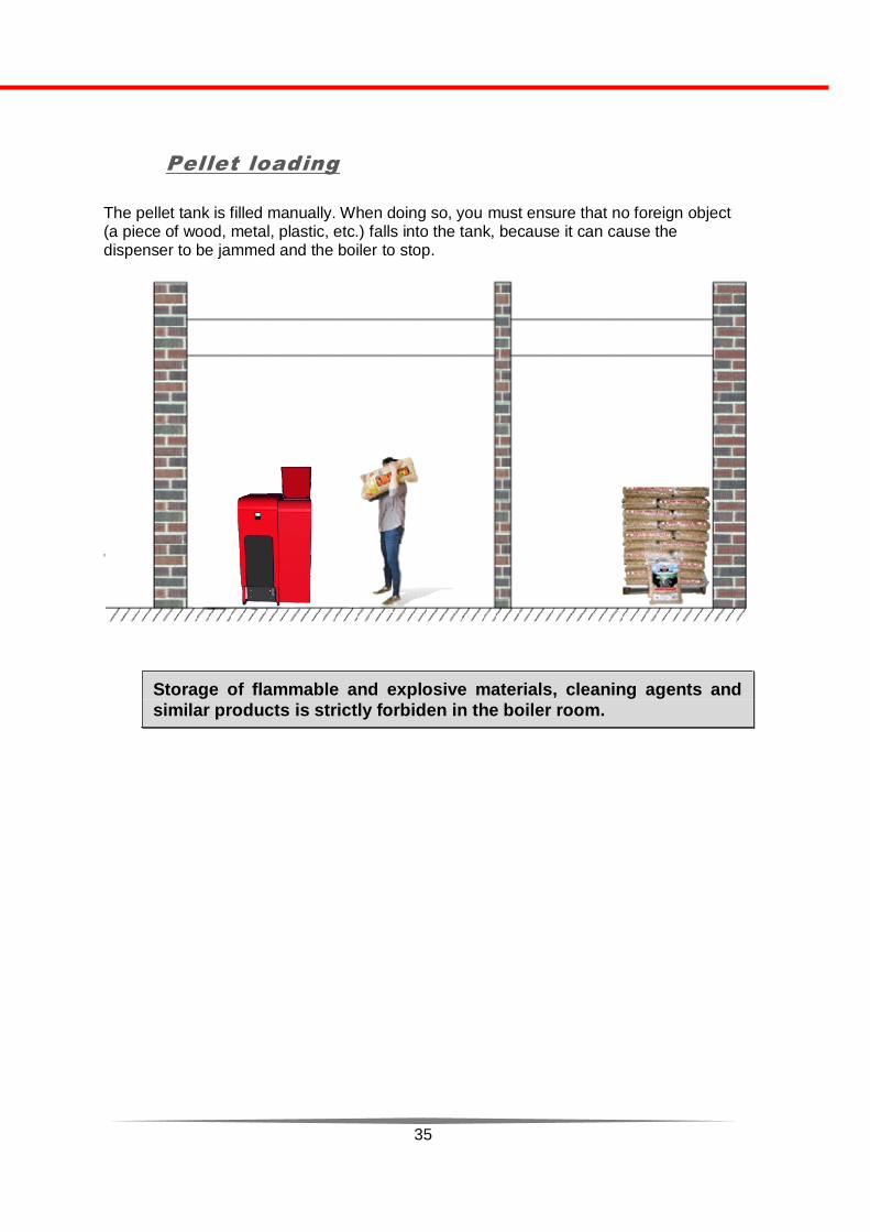
The pellet tank is filled manually. When doing so, you must ensure that no foreign object (a piece of wood, metal, plastic, etc.) falls into the tank, because it can cause the dispenser to be jammed and the boiler to stop.
Storage of flammable and explosive materials, cleaning agents and
similar products is strictly forbiden in the boiler room.
36
5. USING THE BOILER
Initial start
The commissioning and first boiler startup must be done by an
authorized servicer, otherwise, the warranty will not be valid.
During the first startup, condensation and leakage may occur. This is a natural occurrence and is not a reason for concern. It is only necessary to wipe the condensate with a dry cloth.
Protecting the return line
The boiler should be fitted with the protection of the return line. The return temperature should be between 55 ° C and 60 ° C, thus preventing the formation of tar and forming the condensate inside the boiler, and therefore prolonging the life of the boiler.
Cleaning and maintenance of the boiler
To ensure the flawless operation of the boiler, it must be cleaned and maintained regularly. A dirty boiler will have a higher consumption of pellet, so regular cleaning will automatically reduce the heating costs. The cleaning is divided into regular and periodic. Regular cleaning means removing the ash from the box and checking of the burner grid contamination. Periodic cleaning is performed at least once a year (our recommendation is to thoroughly clean the boiler twice - at least once during the heating season and once after the heating season ends).

37
6. BOILER CONTROL
EcoLogic boiler is equiped with one of best electronic control unit for pellet boilers in Europe. Controling the boiler is very easy. All users who serve the boiler are obliged to read the instructions and keep them
near the boiler.
Boiler control is the central electronic component. It consists of a display mounted on a boiler and a control unit located in the boiler itself. The basic function of the regulation is to ensure a reliable ignition of the fuel, optimum combustion conditions and a controlled ignition sequence.
The flame sensor, located in the burner itself, measures the flame temperature, according to which the regulation controls the burning. It recognizes automatically the pellet quality and changes the parameters as needed (amount of pellet inserted and fan power). This mode of operation provides perfect combustion throughout the boiler range (30% to 100% power).
There are different markings on the display that give information to the user about the status of the boiler and the functions it performs.
Navigation
The contents and appearance on the Home screen differ depending on the selected settings. The commands and key functions are displayed as:

38
SYMBOL Description
MENI Press MENU buton to enter settings menu
„Back“ to previous menu level
Moving trough menu
+ - With PLUS (+) and MINUS (-) you cn change the values
OK Button OK for accepting the desired value
SET Active with options (functions) that can be changed.
ON START THE BOILER: On the start display screen press the button
ON to start the boiler.
In the user menu, this button is used to activate certain functions
(eg. Activate heating circuit 1) .
OFF SWITCH OFF BOILER :
On the start display screen press button OFF to stop the boiler.
In the user menu, this button is used to deactivate certain functions
(eg. Deactivate heating circuit 1) .
QUIT Displayed only in case of error or boiler malfunction.
When you press the ignition key, the grate and pipe exchanger cleaning phase begins. The cleaning phase ends when the grid makes three full turns. Then the phase of the ignition begins. The dispenser for the pellet, heater and suction fan for flue gases are than in operation. The dispenser performs the initial insertion of pellet into the burner for combustion. At the same time, the heater is switched on and the pellets are burned, while the suction fan performs the required combustion pressure. When the flame temperature sensor finds that the flame has reached the required temperature, the boiler starts a new phase of stabilizing the flame, and then goes into normal work operation.
The boiler works at maximum power until it reaches the set temperature. When the set temperature is reached, the boiler reduces the working power (modulates its work). If the default temperature exceeds 5 ° C the boiler will turn off. Once the temperature drops below the set for 5 ° C, the boiler will start again the ignition phase and return to normal operation.
39
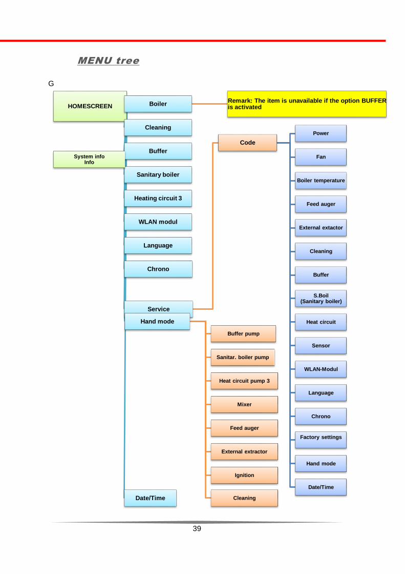
MENU tree
G
HOMESCREEN BoilerRemark: The item is unavailable if the option BUFFERis activated
Cleaning
Buffer
Sanitary boiler
Heating circuit 3
WLAN modul
Language
Chrono
Service
Code
Power
Fan
Boiler temperature
Feed auger
External extactor
Cleaning
Buffer
S.Boil(Sanitary boiler)
Heat circuit
Sensor
WLAN-Modul
Language
Chrono
Factory settings
Hand mode
Date/Time
Hand mode
Buffer pump
Sanitar. boiler pump
Heat circuit pump 3
Mixer
Feed auger
External extractor
Ignition
Cleaning Date/Time
System infoInfo

40
User menu
The user menu is the basic part of the control control. Through the user menu, we perform basic boiler setup.
User menu sections:
- Changing boiler temperature
- Automatic cleaning function
- Buffer connection settings (puffer/buffer)
- Sanitary boiler settings
- Heat circuit 3 settings
- Control over internet – WLAN modul settings
- Language change
- Service menu
- Checking the work of components
- Time and date adjusting

41
HOMESCREEN BoilerBOILER SET TEMP: XX°C
WORK: 77°C
Note: The item is unavailable if the BUFFER option is activated
Cleaning
HAND CLEANING
-ON
-OFF
Buffer
BUFFER
-NOT AVALIABALE
-BUFFER 2 SENS
Sanitary boilerS. BOILER
-NOT AVALIABLE
-CONECTED
Heating circuit
HEATING CIRCUIT 1
HEATING CIRCUIT -NOT AVALIABLE-PUMP-PUMP + MIXER
HEATING CIRCUIT 2
HEATING CIRCUIT 3
WLAN-Modul --NOT AVALIABLE
-CONECTED
Language
DEUTSCHENGLISHBHS JEZIK
Chrono
CHRONO
BLOCKS WEEKLY PROGRAM:
XX
WORK: 2
Service
Hand mode
Date / Time Date/Time 2018/04/0609:45
"PUMP + MIXER" OPTIONS CAN BE PERMITTED ONLY FOR ONE
HEATING CIRCUIT.FOR OTHER HEATING CIRCUITS IT CAN ONLY
USE PUMP OUTPUT

42
Manual mode
Manual mode is used only to check the operation of individual
components of the boiler
By entering a specific menu item you can check the operation and functioning of:
- Buffer pump / Heating circuit pump 1
- Sanitary Water tank Pump / Heating circuit pump 2
- Heating circuit pump 3
- Flue gas fan
- Work of the mixing valve motor
- Work of motor for pellet dispenser
- External pellet auger motor
- Heater
- Moving grate motor
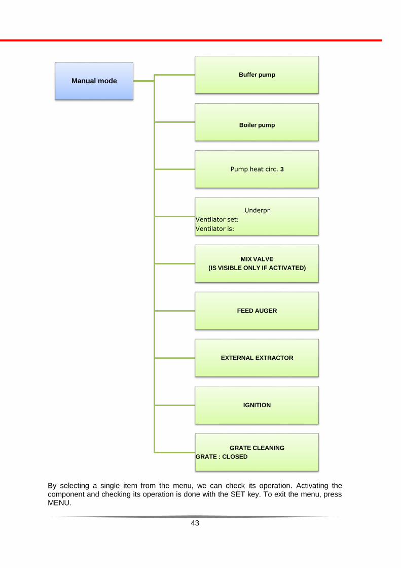
43
By selecting a single item from the menu, we can check its operation. Activating the component and checking its operation is done with the SET key. To exit the menu, press MENU.
Manual modeBuffer pump
Boiler pump
Pump heat circ. 3
Underpr
Ventilator set:
Ventilator is:
MIX VALVE
(IS VISIBLE ONLY IF ACTIVATED)
FEED AUGER
EXTERNAL EXTRACTOR
IGNITION
GRATE CLEANING
GRATE : CLOSED

44
Service
The service section is intended for professional staff and can only be accessed after entering the appropriate code.
It is strictly forbidden for users to enter the service parameters because incorrect modifications can cause incorrect boiler operation and even explosion.
Manufacturer, ThermoFLUX d.o.o. is not responsible for any malfunctions and possible injuries that may occur if the user changes
the parameters.

45
USER MENU
Basic boiler setup menu or user menu. In this section, you can set the boiler temperature, water temperature in tank (puffer), set pump mode and mixing valve, set the WLAN port, change the language, system time and program boiler operation.
In the user menu you can enteer pressing the MENU button.
Boiler temperature settings
The method of changing the water temperature in the boiler will be explained in the next section. The same procedure is used to modify the other parameter values and programs.
The boiler water temperature can be set in the range of 55 ° C to 85 ° C.
Press key MENU:
--------------------------------------------------- 1. Chose desired area by arrows (1) and
confirm with OK (key SET) (2)
-----------------------------------
2. Press key SET
------------------------------------------------
3. With the arrows chose desired
temperature
1
2

46
4. Confirm the desired temperature and save the setting by pressing OK (key SET), and then to
go back by pressing
Mark WORK means “factory settings“ .
Remark:
If the buffer menu option is activated, the boiler water temperature setting is not
visible.
Water temperature in tank (puffer)
The water temperature in the tank can be set in the range of 40 ° C to 85 ° C . Increasing and decreasing the temperature is done in the same way as changing the temperature in the boiler. After selecting the desired value to save, confirm by pressing OK (SET key).
The following diagram describes how to set certain temperatures.
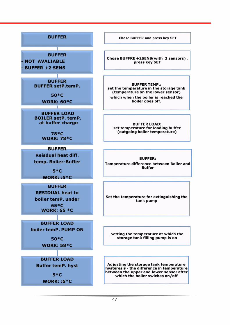
47
BUFFER Chose BUFFER and press key SET
BUFFER
- NOT AVALIABLE
- BUFFER +2 SENS
Chose BUFFRE +2SENS(with 2 sensors) , press key SET
BUFFERBUFFER setP.temP.
50*C
WORK: 60*C
BUFFER TEMP.: set the temperature in the storage tank
(temperature on the lower sensor)
which when the boiler is reached the boiler goes off.
BUFFER LOADBOILER setP. temP.
at buffer charge
78*CWORK: 78*C
BUFFER LOAD: set temperature for loading buffer
(outgoing boiler temperature)
BUFFER
RESIDUAL heat to
boiler temP. under
65*CWORK: 65 *C
Set the temperature for extinguishing the tank pump
BUFFER LOAD
boiler temP. PUMP ON
50*C
WORK: 58*C
Setting the temperature at which the storage tank filling pump is on
BUFFER LOAD
Buffer temP. hyst
5*C
WORK: :5*C
Adjusting the storage tank temperature hysteresis - the difference in temperature between the upper and lower sensor after
which the boiler swiches on/off
BUFFER
Reisdual heat diff.
temp. Bolier-Buffer
5*C
WORK: :5*C
BUFFER:
Temperature difference between Boiler and Buffer

48
Sanitary water temperature (HWS temperature)
Temperature in the sanitary boiler (HWS) can be set in the range of 40 °C to 70 °C. This menu item is visible if the output for the sanitary boiler is activated and if the temperature sensor for the storage tank is mounted.
Increasing and decreasing the temperature is done in the same way as changing the temperature in the boiler. After selecting the desired value to save, confirm by pressing OK (SET key).
The choice of sanitary water temperature is very important, it depends not only on the type of consumer, but is also limited to legionella preservation conditions. Legionella is a bacteria causing the so-called legionnaire disease (one type of pneumonia), which can be deadly. Legionela are propagated at
temperatures between 32 ° C and 42 ° C and can be destroyed at temperatures of about 60°C to 70°C. In accumulation systems, it is necessary at least to achieve such temperatures for a short time, in order to destroy legionnaires (thermal disinfection). Thermal disinfection is to be performed once a week, for about one hour.
The boiler has an automatic anti-legionela function and it should be activated if a
sanitary boiler is connected.
Heating circuit
Option heating circuit is set during the boiler installation.
• Heating circuit 1 is used for water tank pump or heating circuit pump 1.
• Heating circuit 2 is used for sanitary water tank pump or heating pump 2.
• Heating circuit 3 can only be used for the heating circuit pump 3.
The output for the mixing valve motor can only be assigned to one heating circuit.
Setting the temperature in the heating circuit:

49
HEATING CIRCUIT Select HEATING CIRCUIT on the user menu and press the
SET button
HEATING CIRCUIT
- HEATING CIRCUIT 1
- HEATING CIRCUIT 2
- HEATING CIRCUIT 3Chose HEATING CIRCUIT1
HEATING CIRCUIT1
NOT AVALIABLEPUMPPUMP+MIXER
Chose PUMP
HEATING CIRCUIT 1
HC. FLOW SET TEMP.
70WORK : 77
Set the default temperature in the heating circuit.
Note, the temperature is the same for all heating circuits,
EXCEPT circuit with mixing valve
HEATING CIRCUIT
HEAT CIRC. RES.HEAT USE TO5
*CWORK: 5 *C
Turn-OFF temperature (STOP) of the circulation
pump in the heating circuit.
HEATING CIRCUIT
HEAT CIRC. PUMP ON AT55
*CWORK: 55 *C
Turn-on temperature (START) of the circulation
pump in the heating circuit.
HEAT CIRCUITHeat Circ.Hyst
2 *CWORK: 4 *C
Adjust the heating circuit hysteresis

50
Note: When setting boiler temperature and heating circuit.
The heating circuit temperature is lower than the default boiler
temperature
During operation, the regulation follows the default temperature of the HEATING CIRCUIT. If this temperature is lower than the set temperature of the BOILER , the regulation will turn off the boiler as soon as it reaches the HEATING CIRCUIT temperature, increased for hysteresis. The display will show BOILER PAUSE.
The heating circuit temperature is higher than the default boiler
temperature
During operation, the control follows the set temperature of the HEATING CIRCUIT and if this temperature is higher than boiler set temperature, the control will turn off the boiler as soon as it reaches the HEATING CIRCUIT temperature. The display will show BOILER OFF EXTINGUISHING
HEATING CIRCUIT + MIXING VALVE
When one of the heating circuits is activated with the mixing valve, three more operation settings are displayed:
HEATING CIRCUIT
PUMP + MIXING VALVE Select a HEATING CIRCUIT + MIXING
VALVE in the user menu and press the SET button
HEATING CIRCUIT
HC. flow set temp.40
WORK : 50 .
Setting the output temperature to the heating circuit (sensor must be placed
after the mixing valve) eg floor heating
HEATING CIRCUIT
WORK TIME MIXER
90 SECWORK : 90 .
Setting the time of the work formixing valve
HEATING CIRCUITMIN. TIME WORK M. VALVE
1 SECWORK: 0,30 .
Setting the minimum time mixing valve

51
WLAN modul*
This section of the menu activates the WLAN module for controlling the boiler operation via the Internet. The connection method and detailed instructions are supplied with the module.
* NOTE: The WLAN module is optional and not supplied with the boiler.
Language
This section of the menu is used for change the language. You can chose :
- GERMAN
- ENGLISH
- BHS language
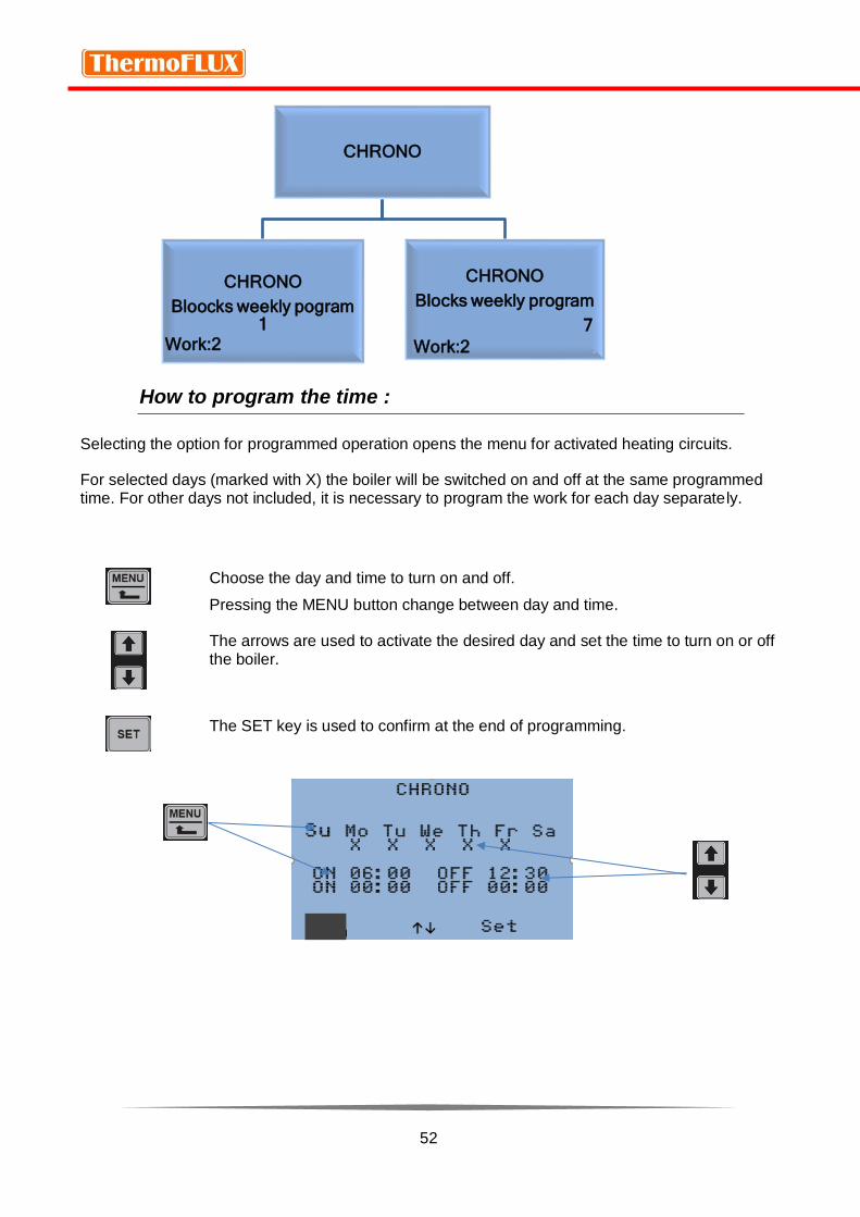
CHRONO PROGRAM
Boiler chrono programming is done for those heating circuits that are activated in the settings. For each heating circuit programming work must be done separately.
Example:
If we have two heating circuits and we chose Heating Circuit 1 to work from 7:00 to 10:00. The boiler will turn on and during the selected time only the pump from the Heating Circuit 1 will run. Heating circuit 2 (pump) will not be active at that time. To make both heating circuits work, it is
necessary to set the desired time on the second circuit.
When selecting the chrono operation it is possible to select a group of 1 to 7 different times for switching on and off for individual heating circuits. Programming is done for days that are marked. The initial (factory) setting is for two times off and on.
Fr 2018-4-6 09:42
LANGUAGE
CHRONO
SERVICE (v)
MANUAL MODE
MENU ↑↓ OFF
52
How to program the time :
Selecting the option for programmed operation opens the menu for activated heating circuits.
For selected days (marked with X) the boiler will be switched on and off at the same programmed time. For other days not included, it is necessary to program the work for each day separately.
Choose the day and time to turn on and off.
Pressing the MENU button change between day and time.
The arrows are used to activate the desired day and set the time to turn on or off the boiler.
The SET key is used to confirm at the end of programming.
CHRONO
CHRONO
Bloocks weekly pogram 1
Work:2 .
CHRONO
Blocks weekly program
7
Work:2 .

53
In the example, we see that the storage tank (buffer) is programmed to start only on working days from 05:00 to 10:00, and the Heating Circuit 3 is scheduled to start every day from 08:00 to 11:00 and then from 15:00 do 22:00.
Note: This example is just an explanation of the programming mode.
When programming the work we have to pay attention that the time for the same
heating circuit does not overlap.
54
Info display
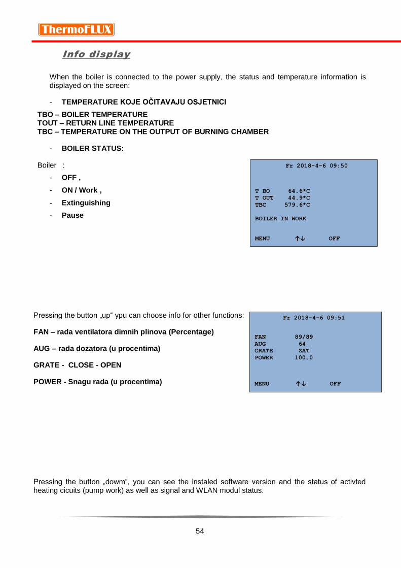
When the boiler is connected to the power supply, the status and temperature information is displayed on the screen:
- TEMPERATURE KOJE OČITAVAJU OSJETNICI
TBO – BOILER TEMPERATURE TOUT – RETURN LINE TEMPERATURE TBC – TEMPERATURE ON THE OUTPUT OF BURNING CHAMBER
- BOILER STATUS:
Boiler :
- OFF ,
- ON / Work ,
- Extinguishing
- Pause
Pressing the button „up“ ypu can choose info for other functions:
FAN – rada ventilatora dimnih plinova (Percentage)
AUG – rada dozatora (u procentima)
GRATE - CLOSE - OPEN
POWER - Snagu rada (u procentima)
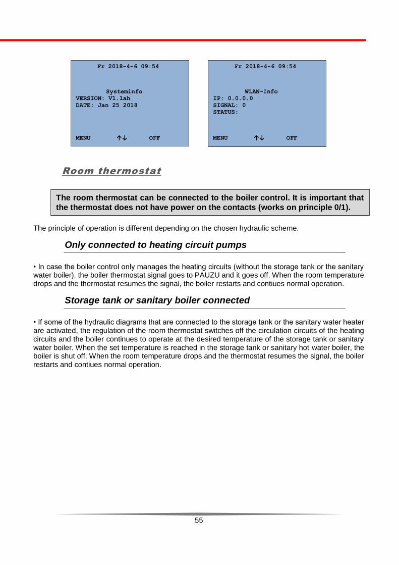
Pressing the button „dowm“, you can see the instaled software version and the status of activted heating cicuits (pump work) as well as signal and WLAN modul status.
Fr 2018-4-6 09:51
FAN 89/89
AUG 64
GRATE ZAT
POWER 100.0
MENU ↑↓ OFF
Fr 2018-4-6 09:50
T BO 64.6*C
T OUT 44.9*C
TBC 579.6*C
BOILER IN WORK
MENU ↑↓ OFF
55
Room thermostat
The room thermostat can be connected to the boiler control. It is important that
the thermostat does not have power on the contacts (works on principle 0/1).
The principle of operation is different depending on the chosen hydraulic scheme.
Only connected to heating circuit pumps
• In case the boiler control only manages the heating circuits (without the storage tank or the sanitary water boiler), the boiler thermostat signal goes to PAUZU and it goes off. When the room temperature drops and the thermostat resumes the signal, the boiler restarts and contiues normal operation.
Storage tank or sanitary boiler connected
• If some of the hydraulic diagrams that are connected to the storage tank or the sanitary water heater are activated, the regulation of the room thermostat switches off the circulation circuits of the heating circuits and the boiler continues to operate at the desired temperature of the storage tank or sanitary water boiler. When the set temperature is reached in the storage tank or sanitary hot water boiler, the boiler is shut off. When the room temperature drops and the thermostat resumes the signal, the boiler restarts and contiues normal operation.
Fr 2018-4-6 09:54
Systeminfo
VERSION: V1.1ah
DATE: Jan 25 2018
MENU ↑↓ OFF
Fr 2018-4-6 09:54
WLAN-Info
IP: 0.0.0.0
SIGNAL: 0
STATUS:
MENU ↑↓ OFF

56
7. TROUBLESHOOTING
During boiler operation there are possible errors that can be eliminated without
calling customer service.
No power
In the event of a power failure, there are no signs in the display. It is necessary to check the supply fuse in the house and the main fuse on the boiler located on the side of the boiler. If the fuse is blown, it must be replaced.
ERROR Possible ERROR - SOLUTION
Attention High temp./ STB activated Activated STB switch (overheating of the boiler)
Sensor Buufer up/ Sensor buffer down/ Boiler temperature/ Return
temperature / Burner termperature / Sensor sanitary boiler/ Sensor temp.
Out. interruption/ Short circuit
Some of these sensors is broken or interrupted connection.
In the case of a senso-error, one of the sensors always has the capability to terminate the connection
or short circuit of the sensor.
Call the service
Grate does not work The grate in the burner does not work. Open the fire door and see if anything prevents the grate from
running.
Call service if it is not possible to start operation.
Smoke fan fault The flue gas fan does not work. Check the connection cables. Remove the cover of the heat exchanger and check if something prevents startup of fan blades.
Call service if it is not possible to start operation.
Ignition failed Check the pellet is in the tank. Something may cause stuck. Check if the motorreductor and spiral for the pellet
Make sure the heater is correct.
Call the service

57
Flame extinguish Check the pellet is in the tank.
Check if the motorreductor and spiral for the pellet
Call the service
No pellet Check the pellet is in the tank.
No pellets in the tank - fill the pellet tank.
It is also possible that the following notification appears (not an eror for boiler):
Fehler in Parametern (Greška u parametrima) / Error in parameters
The following errors are written only in the memory of regulation and do not show up on the screen Ignition (Power ON)
Error memory has been initialized
Error example
Resetting the errors
You can annul the errors by pressing the QUIT key.
Before that you need to check the cause of the error and try to remove it. If it is not possible, call an authorized service center.
To reset the error, press QUIT. (SET button)
Fr 2018-4-6 09:59
ERROR:
BOILER OVERHEATED
STB ACTIVATED
QUIT
Fr 2018-4-6 09:59
ERROR:
SMOKE FAN FAULT
QUIT
58
8. START-UP
Ignition sequence and description of regulation
The basic function of the electronic control unit is to ensure a reliable ignition of the fuel, optimum combustion conditions and controlled ignition sequence. Depending on the strength and complexity of the heating system, the parameters are differently read off and controlled. Please note that in some heating systems the number and value of the parameters may deviate from the above examples but the basis of the heating system is always the same.
Before startup the boiler, you need to check:
the tank should be filled with pellets
the pellet tank top cover must be closed
the door must be hermetically sealed
the boiler must be connected to 230 V, 50 Hz
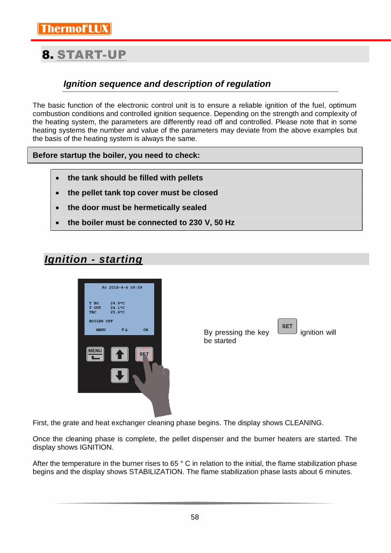
Ignition - starting
By pressing the key ignition will be started
First, the grate and heat exchanger cleaning phase begins. The display shows CLEANING.
Once the cleaning phase is complete, the pellet dispenser and the burner heaters are started. The display shows IGNITION.
After the temperature in the burner rises to 65 ° C in relation to the initial, the flame stabilization phase begins and the display shows STABILIZATION. The flame stabilization phase lasts about 6 minutes.
Fr 2018-4-6 09:59
T BO 24.6*C
T OUT 24.1*C
TBC 25.6*C
BOILER OFF
MENU ↑↓ ON

59
After the stabilization phase is over, the boiler switches to normal operation according to the default parameters and system settings.
Boiler shutdown – switch off
To turn off the boiler press the SET button. The display shows BOILER OFF EXTINGUISH (KESSEL NACHLAUF)
Suction fan goes maximum power and pellet dispenser stops operating.
The duration of the shutdown is determined by the system parameters and lasts until the temperature in the combustion chamber drops below 200 ° C
Auto-adjusting power operation and extinguishing
In the work phase the boiler itself adjusts power operation at the request of the heating system or the water temperature in the system.
Boiler control is programmed so that, when the boiler temperature reaches the default value, it automatically starts to decrease the power output.
If the temperature exceeds the temperature adjusted by user up to +5 ° C , boiler automatically turns off and on the display shows PAUSE.
After the boiler temperature drops below the temperature adjusted by user, it automatically restarts the ignition phase and continues working.
Automatic cleaning
During operation the boiler has a timer which, after a certain time of work, interrupts the dosing, shuts down the boiler and starts the motors for cleaning the grate in the combustion chamber and the motor for heat exchangers. The cleaning interval depends on the strength of the work and can be more frequent or shorter.
The process is fully automated, does not require user's work.
When the cleaning phase is complete, the boiler will re-ignite and continue working.
Re-ignition
In order for the boiler to start work again, either automatically or manually, the cooling cycle conditions must be completed.

60
9. CLEANING AND MAINTENANCE
Cleaning the boiler and its components extends the boiler lifetime and is the basic requirement for normal operation of the boiler itself. It is therefore necessary to clean the boiler thoroughly and carefully.
It is recommended to use the vacuum cleaner for ashes when cleaning the boiler.
Hot surfaces. Obligatory use of gloves and protective equipment
in order to prevent burns.
Regular cleaning of boiler EcoLogic
Regular boiler cleaning means emptying the ashtrays. It is recommended to empty the ash boxes, after having spent 400 to 500 kg of pellets or 2-3 tanks (if pellet is good quality less frequently).
Also, it is necessary to clean the pellet container out of the dust and any foreign objects that may be inside the bag with the pellets.
Open the door and take out the
ash box.
Ash boxes are attached in the
middle and can be separated.
(1)
Empty the ash into a fireproof
container.
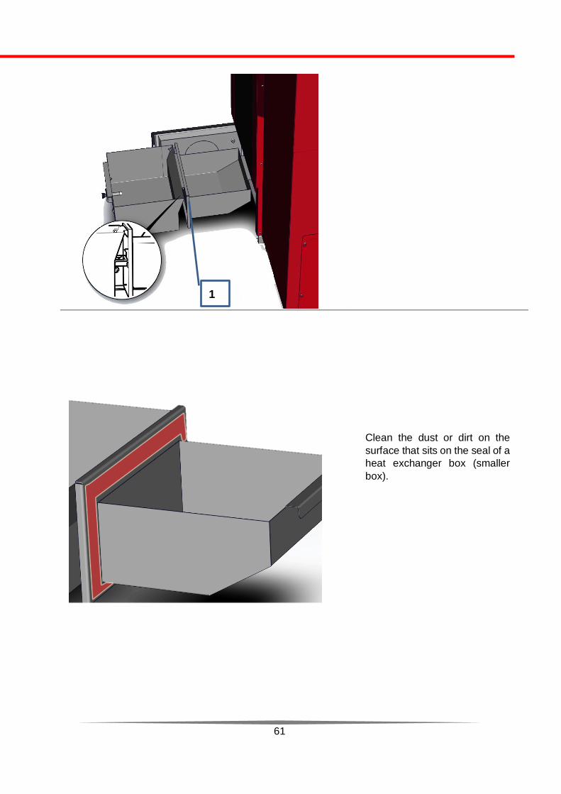
61
Clean the dust or dirt on the
surface that sits on the seal of a
heat exchanger box (smaller
box).
1
62
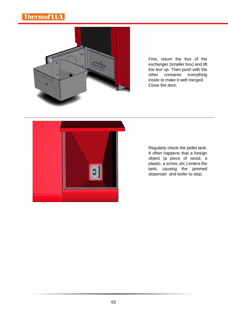
First, return the box of the
exchanger (smaller box) and lift
the levr up. Then push with the
other container everything
inside to make it well merged.
Close the door.
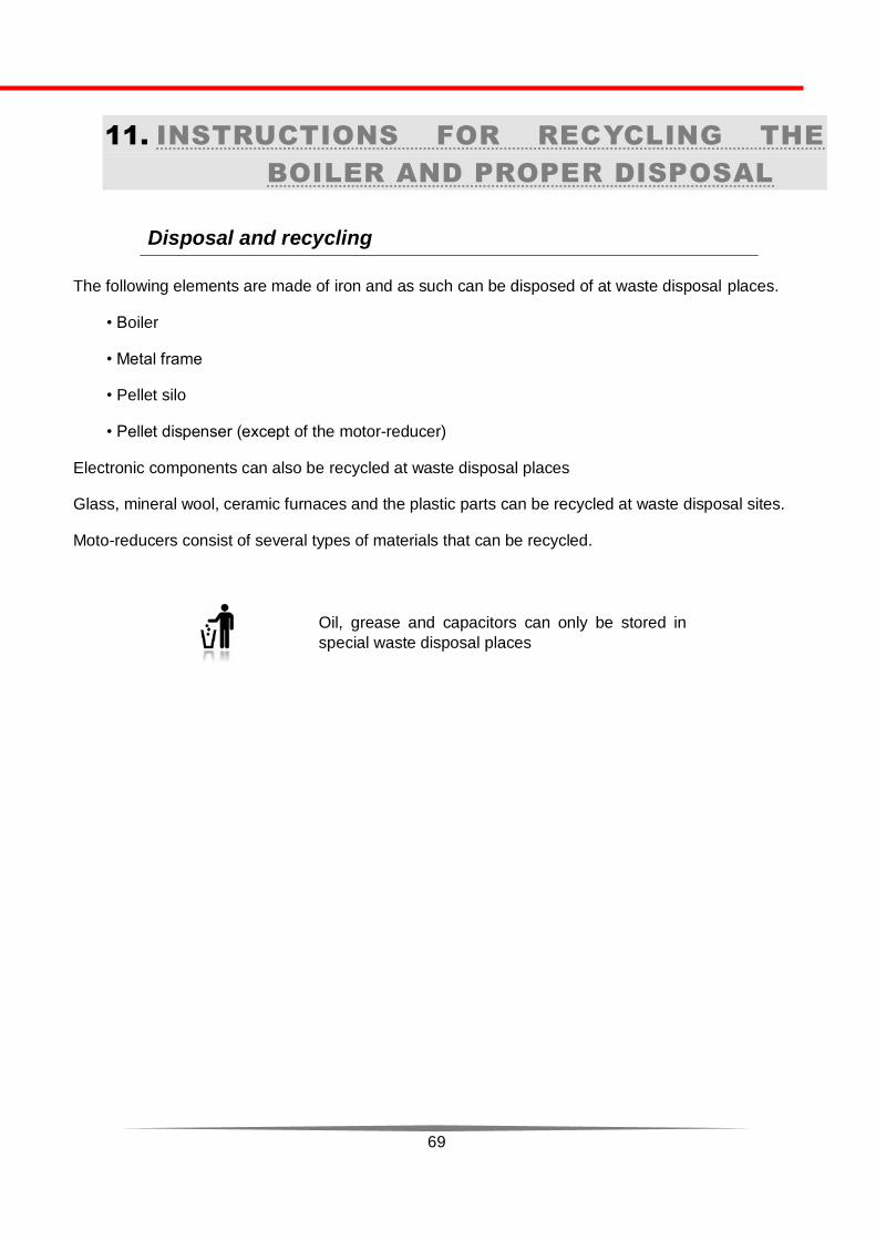
Regularly check the pellet tank.
It often happens that a foreign
object (a piece of wood, a
plastic, a screw, etc.) enters the
tank, causing the jammed
dispenser and boiler to stop.

63
Periodic cleaning of EcoLogic
Periodic cleaning means cleaning the combustion chamber, the ash box and tube heat
exchanger.
Periodic cleaning is done at the latest after:
- 1000 hours of work,
- spending 4 tons of pellets or
- 3 months heating.
Required tools: imbus key 5, wrench M 8, vacuum cleaner for the ash, a brush.
Remove the front panel on
the boiler (black).
The panel is fastened by the
"click" system, and it is
necessary to carefully drag it
down in the lower part to
remove it.

64
Carefully remove the
thermal insulation from the
place where the door of the
burning chamber is.
Remove the door (1) – by
unscrewing two M8 screws
from sides.
Remove the top lid from the
boiler in the way that you first
remove the screws that hold
the cover (1) and then
remove the top cover by
pulling it up (2)
1
1 2

65
Remove the flame
temperature sensor from the
housing (1), then remove the
four M 8 screws on the heat
exchanger cover.
Raise and remove the heat
exchanger cover upwards.
Leave it to the side, taking
care not to damage the
flame temperature sensor
tube.
1

66
Use a suitable brush to clean
the walls thoroughly.
Clean the pipe exchanger,
the inlet between the
combustion chamber (1) and
the smoke fan outlet (2) out
of the ash deposit.
Use a suitable brush to clean
the walls inside the burning
chamber thoroughly.
(1) and after that use
vacuum cleaner to clean the
ash from inside of the
burning chamber.
Put the small extension of a
vacuum cleaner to clean the
top of the suction hose and
deeply clean holes inside of
burning chamber and
openings for primary and
secondary air.
Note: Mark the positions
of flaps and after cleaning
put them back in same
position.
1
1
2
1

67
Remove the flue pipes and
remove the ash which is
accumulated in them.
Cleaning the flue pipes must
be done because the ash is
often accumulated in the
horizontal parts.
Recommendation of the manufacturer is that an annual inspection and review of the boiler and its components is done by an authorized service center
Regular maintenance and servicing by authorized service will allow long work without the problem for your boiler and heating system. The system will be environmentally friendly, with a high degree of efficiency and reduced emissions and low fuel consumption.

68
10. OPERATION PROBLEMS
Electrical power failure
In case of power failure during operation and the return of supply, the control unit will check the boiler status and temperature.
The pumps continue to work to prevent system overheating and to cool the boiler. If the flame temperature sensor has received a signal that the temperature in the combustion chamber is high, a fan is switched on to burn the remaining pellet in the combustion chamber and if the temperature continues to rise the boiler continues to operate.
If the temperature is not high enough and the sensor detects a temperature fall, below the default, the fan will work until the remaining pellet burns and then clean the burner grid. If the programmed time is active, the boiler will restart.
Overheating
If the boiler temperature reaches the limit of 90 ° C, all pumps in the system will start to cool down the boiler. If this does not help and the temperature raises up to 95 ° C, the safety thermo switch (STB)
will be activated by sending the signal to control unit, the display shows BOILER OWERHEATING / STB ACTIVATED and the boiler stops working.
The switch is located on the side of the boiler and is in black color. To reset it, first wait for the boiler to cool down, unscrew the plastic cap and use a suitable tool to reset the switch. After that, it is possible to restart the boiler.
69
11. INSTRUCTIONS FOR RECYCLING THE
BOILER AND PROPER DISPOSAL
Disposal and recycling
The following elements are made of iron and as such can be disposed of at waste disposal places.
• Boiler
• Metal frame
• Pellet silo
• Pellet dispenser (except of the motor-reducer)
Electronic components can also be recycled at waste disposal places
Glass, mineral wool, ceramic furnaces and the plastic parts can be recycled at waste disposal sites.
Moto-reducers consist of several types of materials that can be recycled.
Oil, grease and capacitors can only be stored in
special waste disposal places

70
12. GUARANTEE
The boiler must only be operated as intended and in technically perfect condition! Especially, errors tending to affect the safety need to be cleared immediately!
In the interest of the continuous development and improvement of our products, we reserve all rights to make technical changes to the information contained in our printed material. Changes, errors and printer's errors do not justify claims for damages.
Only original spare parts must be used.
In addition to the guidelines in this operation manual, please follow general guidelines for safety and accident prevention. The boier must be switched off at least 20 minutes before any work on the boiler (maintenance works, unscrewing covers, etc.)
Warranty period
The warranty period is 5 years on the body of the boiler and the coating, and 2 years on the electrical component (regulation and its parts, motors, heater).
ThermoFLUX d.o.o. is responsible for providing the service from the guarantee
conditions on the territory of Bosnia and Herzegovina.
The guarantee in other countries is provided by an authorized importer /
distributor.
Terms
The boiler must be put into operation by a professional - servicer, authorized by
the ThermoFLUX d.o.o, or an authorized importer.
The boiler must operated in accordance with the requirements in this manual.
The boiler must be installed in accordance with applicable state laws and
regulations.
The quality of pellet must meet the applicable standards set out in this manual.
If the servicer installs the boiler without meeting all the necessary conditions, the
servicer undertakes all responsibility and additional costs that may arise.

71
Warranty exclusions
Warranty obligations shall not apply to defects caused by:
• Poor and negligent handling and maintenance
• Improper and unauthorized opening and repair of the device
• Improper installation, mechanical damage or overload that is not allowed
• Failure to follow instruction manual.
• Failure to comply with installation and commissioning instructions
• Damage caused by external influences such as fire and water, lightning strike,
excessive voltage, or damage caused during transport.
Manufacturer contact
ThermoFLUX d.o.o. Bage br 3, 70101 Jajce BOSNIA AND HERZEGOVINA TEL: +387 30 657 100
E-MAIL: [email protected]
WEB : www.thermoflux.ba

72
ThermoFLUX d.o.o. Bage br.3, Jajce
Bosna i Hercegovina Tel/fax +387-30-657-100
www.thermoflux.ba
Uputstvo za upotrebu EcoLogic K Ver1.2017