pea-rp100, 125, 140gaa - mitsubishi electric
TRANSCRIPT

INSTALLATION MANUALFor safe and correct use, please read this installation manual thoroughly before installing the air-conditioner unit.
Air-Conditioners
PEA-RP100, 125, 140GAA
<ORIGINAL>
EnglishFOR INSTALLER

2
B
A
Bottom of indoor unit
Bottom of indoor unit
Ceiling beam
Maintenance access space
Electric box
Supply airIntake air
Ceiling Access door 3
Maintenance access space
Electric box Drain pan
Ceiling
Electric box
Intake air
Supply airAccess door 3
Access door 3
Intake air
Supply air
Ceiling Access door 1 Access door 2
Electric box
Drain pan
Maintenance access space
① When connecting inlet duct.② When installing the suspension fixtures prior to
installation of the indoor unit without inlet duct.③
①
②③
When hanging the indoor unit directly without inlet duct.
When connecting inlet duct.When installing the suspension fixtures prior to
installation of the indoor unit without inlet duct.When hanging the indoor unit directly without inlet duct.
Electric box
Access door 2Access door 1
Ceiling Access door 2
Ceiling beam
Supply airIntake air
Electric box
Min
.300
mm
Min
.500
mm
Min
.500
mm
Min
.300
mm
425
685
200
585
50
1754
200
585
0 ~
150
400
7525
1304400 200
2001304400
0 ~ 150
(450 x 450) (450 x 450)
400
2575
①②
③
①
②③
3 3.2[Fig. 3-2-1] [Fig. 3-2-2]
[Fig. 3-2-4] [Fig. 3-2-5]
[Fig. 3-2-3]
[Fig. 3-2-6]
(Viewed from the direction of the arrow A)
(Viewed from the direction of the arrow B)
(Unit: mm)
3
4[Fig. 4-1]
Unit body Lifting machine
5[Fig. 5-1-1]
Center of gravity
5.1
98 680
200 1300
235
4.1
A30
B
*1
A30
B
10
[Fig. 5-1-2] [Fig. 5-1-3]
Nut Washer
Be sure to attach a U-shaped washer (4 washers in total).
6øB
øA
[Fig. 6-1]
Indoor unit Outdoor unit
6.1
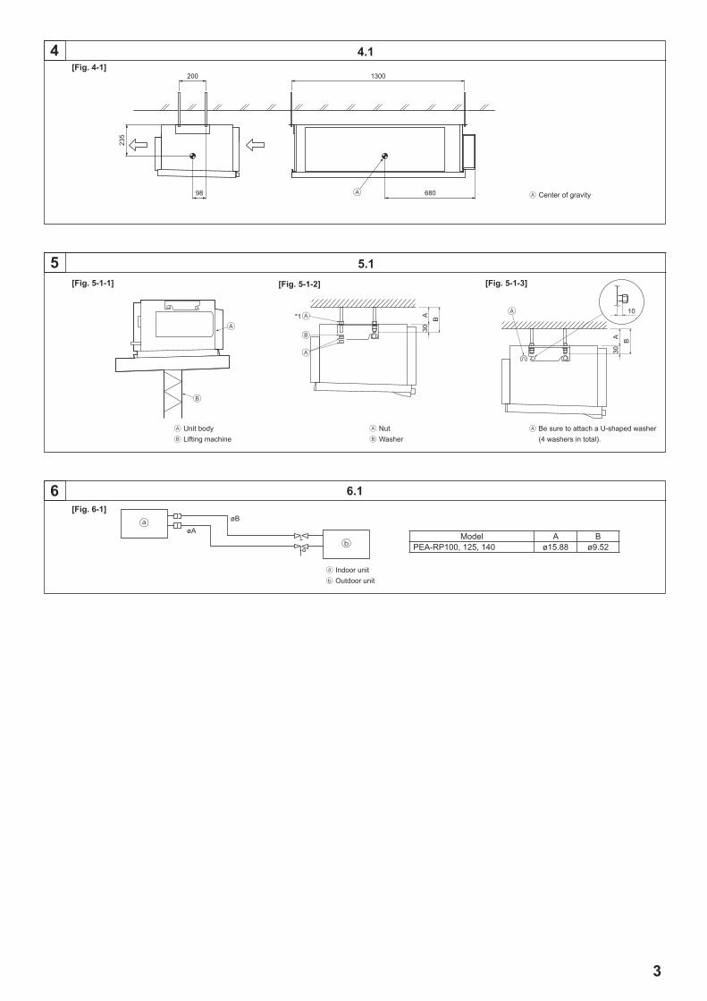
Model A BPEA-RP100, 125, 140 ø15.88 ø9.52

4
[Fig. 6-5]
6
6.5
Insulator Drain pipe R1 Drain pan 70 mm 2 × 70 mm 35 mm Downward slope 20 mm/m or more Drain trap The drain pipe should extend below this level. Open drain
90°
A
[Fig. 6-3-2]
Pipe cover (small) (accessory) Caution: Pull out the thermal insulation on the refrigerant piping at
the site, insert the flare nut to flare the end, and replace the insulation in its original position.
Take care to ensure that condensation does not form on exposed copper piping.
Liquid end of refrigerant piping
Gas end of refrigerant piping Site refrigerant piping Main body Pipe cover (large) (accessory) Thermal insulation (field supply) Pull Flare nut Return to original position
20
20
20
20
[Fig. 6-2-1]
[Fig. 6-2-4]
[Fig. 6-2-2] [Fig. 6-2-3]
Flare nut Copper tube
Burr Copper tube/pipe
Spare reamer Pipe cutter
[Fig. 6-2-5]
[Fig. 6-3-1]
Flaring tool Die Copper tube
Flare nut Yoke
Smooth all around Inside is shining without
any scratches Even length all around
Too much Tilted Scratch on
flared plane
Cracked Uneven Bad examples
Ensure that there is no gap here Plate on main body Band (accessory) Ensure that there is no gap here. Place join upwards.
6.2
Copper tubes Good
No good Tilted
Uneven Burred
6.3

5
8[Fig. 8-1]
8.1
7 7.1
Outdoor unit power supply Earth leakage breaker Wiring circuit breaker or isolating switch Outdoor unit Indoor unit/Outdoor unit connecting wire Remote controller (option) Indoor unit
[Fig. 7-1-1] [Fig. 7-1-2]
[Fig. 7-1-3]
12.52-
20
25~100 mm
10 mm
34
K
25 2 × 100(=200)
I 2 × 130(=260)JA
B
D G
C F
H
250
E
Air inlet Air outlet Access door Ceiling surface Canvas duct Keep duct-work length 850 or more Connect common reference potential wire between duct-work to air conditioner
Inlet duct flange Return air temperature sensor Sensor protection plate Sensor fixture Inlet duct
S1
S1
S1
S2 S2
S2
S2 S2
S2 S3
S3
1
1
2
2
S3
S1S2
L
TB4
TB
TB15
CND
CND
CN3C
CN3C
CN22
N
S3
Indoor Control Board A
Indoor Control Board BIndoor Power Board B
Indoor Power Board A
Model A B C D E F G H I J KPEA-RP100, 125, 140 1102 8 × 130 (=1040) 1000 7 × 130 (=910) 330 105 45 31 35 22 95

6
8.2
Use PG bushing to keep the weight of the cable and external force from being applied to the power supply terminal connector. Use a cable tie to secure the cable.
Indoor unit/outdoor unit connecting wire Use ordinary bushing Remote controller cable Tensile force
Terminal block for indoor/outdoor unit connecting wire Terminal block for remote controller cable
[Fig. 8-2-3] [Fig. 8-2-4]
Terminal block box Knockout hole Remove
Screw holding cover (2pc) Cover
[Fig. 8-2-1] [Fig. 8-2-2]
8
12
M1M2
S
[Fig. 8-2-5]
Indoor terminal block Earth wire (green/yellow) Indoor/outdoor unit connecting wire
3-core 1.5 mm2 or more Outdoor terminal block Power supply cord : 2.0 mm2 or more① Connecting cable Cable 3-core 1.5 mm2, in conformity
with Design 245 IEC 57.② Indoor terminal block③ Outdoor terminal block
④ Always install an earth wire (1-core 1.5 mm2)
longer than other cables⑤ Remote controller cable Wire No × size (mm2) : Cable 2C × 0.3 This wire accessory of remote controller (wire length : 10m, non-polar. Max. 500m)⑥ Wired remote controller (option)⑦ Power supply cord Cab le 3 - co re 2 .0 mm 2 o r mo re , i n
conformity with Design 245 IEC 57.
1 2
⑥
⑤
②
④
③
⑦
L N
①

7
For installation in the switch box: For direct installation on the wall select one of the following:• Prepare a hole through the wall to pass the remote controller cord (in order to run the remote controller cord
from the back), then seal the hole with putty.• Run the remote controller cord through the cut-out upper case, then seal the cut-out notch with putty similarly
as above.
Wall Conduit Lock nut Bushing Switch box Remote controller cord Seal with putty Wood screw
B-1. B-2.
[Fig. 8-3-2]
8
AB TB6
To the terminal block on the indoor unit TB6 (No polarity)
[Fig. 8-3-3]
30
46
30
3012
0
83.5
Remote controller profile Required clearances surrounding the remote controller Installation pitch
[Fig. 8-3-1]
8.3

8
Signal receiving unit external Center of Switch box Switch box Installation pitch 6.5 mm (1/4 inch) 70 mm (2 - 3/4 inch) 83.5 ± 0.4 mm (3 - 9/32 inch) Protrusion (pillar, etc)
[Fig. 8-4-3]
Remote controller wire Hole (drill a hole on the ceiling to pass the remote controller wire.) Signal Receiving Unit
Ceiling cassette type, Ceiling concealed type
[Fig. 8-4-4]
Fix tightly with tape. Remote controller wire Order wire
Indoor unit
[Fig. 8-4-2]
[Fig. 8-4-5]
When using the switch box When installing directly on the wall
150 mm (5 - 15/16 inch) Remote controller wire Wiring pipe Locknut
Seal around here with putty Remote controller wire Seal around here with putty
Bushing Switch box Seal around here with putty
Wall
8 8.4
[Fig. 8-4-1]
Outdoor unit Refrigerant address Indoor unit Signal receiving unit
Indoor/outdoor wiring
Signal receiving unit wiring
ICcontrol board A
OC(00)
CN90
TB1
TB4
①
9
8 8.4
[Fig. 8-4-6]
[Fig. 8-4-7]
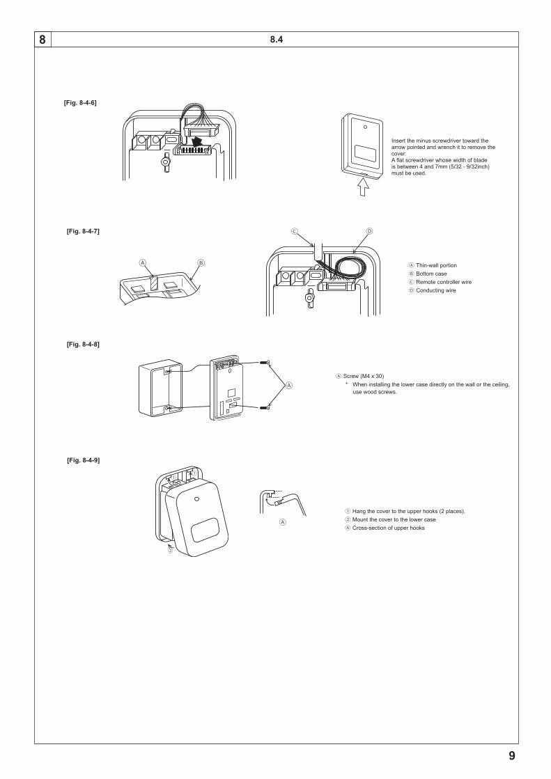
Thin-wall portion Bottom case Remote controller wire Conducting wire
[Fig. 8-4-8]
Screw (M4 x 30)
* When installing the lower case directly on the wall or the ceiling, use wood screws.
Insert the minus screwdriver toward the arrow pointed and wrench it to remove the cover. A flat screwdriver whose width of blade is between 4 and 7mm (5/32 - 9/32inch) must be used.
[Fig. 8-4-9]
①①
②
① Hang the cover to the upper hooks (2 places).② Mount the cover to the lower case Cross-section of upper hooks

10
8 8.4
[Fig. 8-4-10]
IC IC IC ICCN90 CN90 CN90 CN90
Pair number: 0
[Fig. 8-4-11]
ICCN90
ICCN90
Pair number: 0 Pair number: 0
Pair number: 0 Pair number: 0
IC IC IC ICCN90 CN90 CN90 CN90
[Fig. 8-4-13]
[Fig. 8-4-12]
Pair number: 0 Pair number: 1 Pair number: 2 Pair number: 3
Pair number: 0 Pair number: 1 Pair number: 2 Pair number: 3
Pair number: 0 Pair number: 0 Pair number: 0 Pair number: 0
CN2A
CN3C
SW2
SW1
JP1
JP2JP3
JP41JP42
CN22
CN2L
CNXA2
CN32
SWE
CN20
CN90
CN105
CN41
CN4F
CN51
CNXB2
CNXC2
CN44
ON
OFF
<Indoor controller board>
ON/OFF TEMP
FAN
VANE
TEST RUN
AUTO STOP
AUTO START
h
min
LOUVER
MODE
CHECK
RESETSET CLOCK
CHECK
②,④
③
[Fig. 8-4-14]

11
9
[Fig. 9-2-1] [Fig. 9-2-2]
9.2
˚C˚C
SIMPLE
PAR-21MAA
ON/OFF
FILTER
CHECK
OPERATION CLEAR
TEST
TEMP.
MENU
BACK DAYMONITOR/SET
CLOCK
ON/OFF
TEST RUNCOOL, HEAT
˚C˚C
SIMPLE
PAR-21MAA
ON/OFF
FILTER
CHECK
OPERATION CLEAR
TEST
TEMP.
MENU
BACK DAYMONITOR/SET
CLOCK
ON/OFF
ON/OFF button Test run display Indoor temperature liquid line
temperature display ON/OFF lamp Power display
Error code display Test run remaining time display Set temperature button Mode selection button Fan speed button TEST button
8 8.5
[Fig. 8-5-1]
PAR-21MAA
ON/OFF
FILTER
CHECK
OPERATION CLEAR
TEST
TEMP.
MENU
BACK DAYMONITOR/SET
CLOCK
ON/OFF
Ⅰ
Ⅱ Ⅲ Ⅳ
Ⅰ
Ⅰ
Ⅳ
Ⅱ
Filter button (<Enter> button) TEST button Set Time button Timer On/Off button (Set Day button) Mode selection button Set temperature button Timer Menu button (Monitor/Set button)
Mode number Setting number Refrigerant address Unit number
Ⅰ
Ⅱ
Ⅲ
Ⅳ
③
① ②
CHECK CHECK
CHECKCHECK
④
ON/OFF TEMP
FAN
VANE
TEST RUN
AUTO STOP
AUTO START
h
min
LOUVER
MODE
CHECK
RESETSET CLOCK
CHECK
Hour button Minute button TEMP button TEMP button ON/OFF button CHECK button
[Fig.8-5-2]
[Fig. 9-3]
TEST RUN buttonMODE buttonFAN buttonVANE button
9.3
ON/OFF TEMP
FAN
VANE
TEST RUN
AUTO STOP
AUTO START
h
min
LOUVER
MODE
CHECK
RESETSET CLOCK
TEST RUN
CHECK button Refrigerant address TEMP. button IC: Indoor unit
OC: Outdoor unit Check code

12
10[Fig. 10-1]
Indoor unitUnionLiquid pipeGas pipeStop valveOutdoor unitRefrigerant gas cylinder operating valve
Refrigerant gas cylinder for R410A with siphon
Refrigerant (liquid)Electronic scale for refrigerant chargingCharge hose (for R410A)Gauge manifold valve (for R410A)Service port
10.1

13
Contents1. Safety precautions ...................................................................................132. Selecting the installation location ............................................................133. Selecting an installation site & Accessories ............................................144. Fixing hanging bolts ................................................................................145. Installing the unit .....................................................................................146. Refrigerant piping work ...........................................................................15
• Pleasereporttoortakeconsentbythesupplyauthoritybeforeconnectiontothesystem.
• Besure to read “The followingshouldalwaysbeobserved for safety”beforeinstallingtheairconditioner.
• Besuretoobservethecautionsspecifiedhereastheyincludeimportantitemsrelatedtosafety.
• Theindicationsandmeaningsareasfollows.Warning:
Couldleadtodeath,seriousinjury,etc.
Caution:Could lead toserious injury inparticular environmentswhenoperatedincorrectly.• Afterreadingthismanual,besuretokeepittogetherwiththeinstruction
manualinahandyplaceonthecustomer’ssite.
Symbolsputontheunit : Indicates an action that must be avoided.
: Indicates that important instructions must be followed.
: Indicates a part which must be grounded.
: Indicates that caution should be taken with rotating parts.
: Indicates that the main switch must be turned off before servicing.
: Beware of electric shock.
: Beware of hot surface.
Warning:Carefullyreadthelabelsaffixedtothemainunit.
Warning:• Donotuserefrigerantotherthanthetypeindicatedinthemanualsprovidedwiththeunitandonthenameplate.
- Doing so may cause the unit or pipes to burst, or result in explosion or fire during use, during repair, or at the time of disposal of the unit.
- It may also be in violation of applicable laws. - MITSUBISHI ELECTRIC CORPORATION cannot be held responsible for
malfunctions or accidents resulting from the use of the wrong type of refrigerant.• Donotinstallitbyyourself(customer). Incomplete installationcouldcause injurydue to fire, electric shock,theunit fallingor leakageofwater.Consult thedealer fromwhomyoupurchasedtheunitorspecialinstaller.
• Thisapplianceisnotintendedforusebypersons(includingchildren)withreducedphysical, sensoryormental capabilities,or lackof experienceandknowledge,unless theyhavebeengivensupervisionor instructionconcerninguseoftheappliancebyapersonresponsiblefortheirsafety.
• Thisapplianceisintendedtobeusedbyexpertortrainedusersinshops,inlightindustryandonfarms,orforcommercialusebylaypersons.
• Installtheunitsecurelyinaplacewhichcanbeartheweightoftheunit. Wheninstalledinaninsufficientstrongplace,theunitcouldfallcausinginjured.• Use thespecifiedwires toconnect the indoorandoutdoorunitssecurelyandattachthewiresfirmlytotheterminalboardconnectingsectionssothestressofthewiresisnotappliedtothesections.
Incompleteconnectingandfixingcouldcausefire.• Donotuse intermediateconnectionof thepowercordor theextensioncordanddonotconnectmanydevicestooneACoutlet.
Itcouldcauseafireoranelectricshockduetodefectivecontact,defective
insulation,exceedingthepermissiblecurrent,etc.• Checkthattherefrigerantgasdoesnotleakafterinstallationhascompleted.• Performtheinstallationsecurelyreferringtotheinstallationmanual. Incomplete installationcouldcauseapersonal injurydue tofire, electricshock,theunitfallingorleakageofwater.
• Performelectricalworkaccordingtotheinstallationmanualandbesuretouseanexclusivecircuit.
If thecapacityof thepowercircuit is insufficientor there is incompleteelectricalwork,itcouldresultinafireoranelectricshock.
• Ifthesupplycordisdamaged,itmustbereplacedbythemanufacturer,itsserviceagentorsimilarlyqualifiedpersonsinordertoavoidahazard.
• Attachtheelectricalpartcovertotheindoorunitandtheservicepaneltotheoutdoorunitsecurely.
Iftheelectricalpartcoverintheindoorunitand/ortheservicepanelintheoutdoorunitarenotattachedsecurely,itcouldresultinafireoranelectricshockduetodust,water,etc.
• Besuretousethepartprovidedorspecifiedpartsfortheinstallationwork. Theuseofdefectivepartscouldcauseaninjuryorleakageofwaterduetoafire,anelectricshock,theunitfalling,etc.
• Ventilatetheroomifrefrigerantleaksduringoperation. Iftherefrigerantcomesincontactwithaflame,poisonousgaseswillbereleased.• Childrenshouldbesupervisedtoensurethattheydonotplaywiththeappliance.• The installer andsystemspecialist shall securesafetyagainst leakageaccordingtolocalregulationorstandards.- Following standards may be applicable if local regulation are not available.
• Payaspecial attention to theplace, suchasabasement, etc.whererefrigerationgascanstay,sincerefrigerationisheavierthantheair.
Caution:• Performgrounding. Donot connect thegroundwire toagaspipe,waterpipearresterortelephonegroundwire.Defectivegroundingcouldcauseanelectricshock.
• Donotinstalltheunitinaplacewhereaninflammablegasleaks. If gas leaksandaccumulates in theareasurrounding theunit, it couldcauseanexplosion.
• Installagroundleakagebreakerdependingontheinstallationplace(whereitishumid).
Ifagroundleakagebreakerisnotinstalled,itcouldcauseanelectricshock.
• Perform thedrainage/pipingworksecurelyaccording to the installationmanual.
If there isadefect inthedrainage/pipingwork,watercoulddropfromtheunitandhouseholdgoodscouldbewetanddamaged.
• Fastenaflarenutwithatorquewrenchasspecifiedinthismanual. When fastened too tight, a flarenutmaybrokenafter a longperiodandcausealeakageofrefrigerant.
2. Selectingtheinstallationlocation
2.1. Indoorunit• Where airflow is not blocked.• Where cool air spreads over the entire room.• Where it is not exposed to direct sunshine.• At a distance 1 m or more away from your TV and radio (to prevent picture from
being distorted or noise from being generated).
• In a place as far away as possible from fluorescent and incandescent lights (so the infrared remote control can operate the air conditioner normally).
• Where the air filter can be removed and replaced easily.• Indoor units must be installed in a ceiling with a minimum height of 2.5 meters.
Warning:Mounttheindoorunitintoaceilingstrongenoughtowithstandtheweightoftheunit.
Note: The phrase “Wired remote controller” in this installation manual refers only to the PAR-21MAA. If you need any information for THE PAR-31MAA, please refer to either the installation manual or initial setting manual which are included in PAR-31MAA box.
7. Duct work ................................................................................................168. Electrical work .........................................................................................179. Test run ....................................................................................................2010. Maintenance ............................................................................................2211. Specifications ..........................................................................................22
1. Safetyprecautions
2.2.Outdoorunit• Where it is not exposed to strong wind.• Where airflow is good and dustless.• Where it is not exposed to rain and direct sunshine.• Where neighbours are not annoyed by operation sound or hot air.• Where rigid wall or support is available to prevent the increase of operation
sound or vibration.• Where there is no risk of combustible gas leakage.• When installing the unit at a high level, be sure to fix the unit legs.• Where it is at least 3 m away from the antenna of TV set or radio. (Otherwise,
images would be disturbed or noise would be generated.)
• Install the unit horizontally.
Caution:Avoid the followingplaces for installationwhereair conditioner trouble isliabletooccur.• Wherethereistoomuchmachineoil.• Saltyenvironmentasseasideareas.• Hot-springareas.• Wheresulfidegasexists.• Otherspecialatmosphericareas.

14
3. Selectinganinstallationsite&Accessories• Select a site with sturdy fixed surface sufficiently durable against the weight of unit.• Before installing unit, the routing to carry in unit to the installation site should be
determined.• Select a site where the unit is not affected by entering air.• Select a site where the flow of supply and return air is not blocked.• Select a site where refrigerant piping can easily be led to the outside.• Select a site which allows the supply air to be distributed fully in room.• Do not install unit at a site with oil splashing or steam in much quantity.• Do not install unit at a site where combustible gas may generate, flow in, stagnate
or leak.• Do not install unit at a site where equipment generating high frequency waves (a
high frequency wave welder for example) is provided.• Do not install unit at a site where fire detector is located at the supply air side. (Fire
detector may operate erroneously due to the heated air supplied during heating operation.)
• When special chemical product may scatter around such as site chemical plants and hospitals, full investigation is required before installing unit. (The plastic components may be damaged depending on the chemical product applied.)
• If the unit is run for long hours when the air above the ceiling is at high temperature/high humidity (due point above 26 °C), due condensation may be produced in the indoor unit. When operating the units in this condition, add insulation material (10-20 mm) to the entire surface of the indoor unit to avoid due condensation.
3.1. Installtheindoorunitonaceilingstrongenoughtosustainitsweight
Warning:Theunitmustbesecurelyinstalledonastructurethatcansustainitsweight.If theunit ismountedonanunstablestructure, itmay fall downcausinginjuries.
3.2. SecuringinstallationandservicespaceSecure enough access space to allow for the maintenance, inspection, and replacement of the motor, fan, drain pump, heat exchanger, and electric box in one of the following ways.Select an installation site for the indoor unit so that its maintenance access space will
not be obstructed by beams or other objects.[Maintenance access space]Secure enough access space to allow for the maintenance, inspection, and replacement of the motor, fan, drain pan, heat exchanger, and electric box in one of the following ways.Select an installation site for the indoor unit so that its maintenance access space will not be obstructed by beams or other objects.
(1) When a space of 500mm or more is available below the unit between the unit and the ceiling. [Fig.3-2-1][Fig.3-2-2]• Create access door 1 and 2 (450x450 mm each) as shown in [Fig.3-2-3]. (Access door 2 is not required if enough space is available below the unit for
a maintenance worker to work in.)• An access hole of the same size as the access door 3 as shown in [Fig.3-2-6]
is required to access drain pan or heat exchanger for replacement. (Required only when the ceiling material cannot be removed.)
(2) When a space of less than 500mm is available below the unit between the unit and the ceiling.
(At least 300 mm of space should be left below the unit as shown in [Fig.3-2-4][Fig.3-2-5].)• Create access door 3 below the electric box and the unit as shown in [Fig.3-2-6].[Fig.3-2-1](P.2)[Fig.3-2-2](P.2)[Fig.3-2-3](P.2)[Fig.3-2-4](P.2)[Fig.3-2-5](P.2)[Fig.3-2-6](P.2)
3.3. IndoorunitaccessoriesThe unit is provided with the following accessories:
No. Name Quantity① Pipe cover (for refrigerant piping joint) Small diameter 1② Pipe cover (for refrigerant piping joint) Large diameter 1
4. Fixinghangingbolts
5. Installingtheunit
5.1.Hangingtheunitbody Bringtheindoorunittoaninstallationsiteasitispacked. Tohangtheindoorunit,usealiftingmachinetoliftandpassthroughthehangingbolts.[Fig.5-1-1](P.3) Unit body Lifting machine
* Two installation methods are available<When hanging the indoor unit directly>
1. Attach a washer and nut(s) to each suspension bolt. (The washers and nuts are to be supplied locally.)
2. Fit the indoor unit to each suspension bolt.
3. Make sure that the unit is positioned level, then tighten each nut.
[Fig.5-1-2](P.3) Nut Washer
(Unit: mm)A B
When using inlet duct 100 or more 130 or moreWhen not using inlet duct 0 or more 30 or more
Nut (*1) is not required if distance A is 0 mm.
<When installing the suspension fixture prior to installation of the indoor unit>
1. Loosen each suspension fixture bolt slightly, and remove the fixture and U-shaped washers.
2. Adjust each suspension fixture bolt.
3. Attach a washer, nut and suspension fixture to each suspension bolt. (The washers and nuts are to be supplied locally.)
4. Hook the indoor unit to the suspension fixtures.
5. Make sure that the unit is positioned level, then tighten each nut.
[Fig.5-1-3](P.3) Be sure to attach a U-shaped washer (4 washers in total).
(Unit: mm)A B
When using inlet duct 100 or more 130 or moreWhen not using inlet duct 25 or more 55 or more
5.2.Confirmingtheunit’spositionandfixinghangingbolts
Use thegagesuppliedwith thepanel toconfirm that theunitbodyandhangingboltsarepositioned inplace. If theyarenotpositioned inplace,itmayresultindewdropsduetowindleak.Besuretocheckthepositionalrelationship.
Install theunithorizontally,usinga level.Ensure that thehangingboltnutsaretightenedtofixthehangingbolts.
Toensurethatdrainisdischarged,besuretohangtheunitatlevelusingalevel.
Caution:Besuretoinstalltheunitbodyatlevel.
4.1. Fixinghangingbolts[Fig.4-1](P.3) Center of gravity
(Give site of suspension strong structure.)
Hangingstructure• Ceiling: The ceiling structure varies from building to one another. For detailed
information, consult your construction company.
• If necessary, reinforce the hanging bolts with anti-quake supporting members as countermeasures against earthquakes.* Use M10 for hanging bolts and anti-quake supporting members (field supply).
① Reinforcing the ceiling with additional members (edge beam, etc.) must be required to keep the ceiling at level and to prevent the ceiling from vibrations.
② Cut and remove the ceiling members.
③ Reinforce the ceiling members, and add other members for fixing the ceiling boards.

15
6. Refrigerantpipingwork6.2.4. Flaringwork
[Fig.6-2-4](P.4) Flaring tool Die Copper tube Flare nut Yoke
• Carry out flaring work using flaring tool.
Pipe diameter(mm)
DimensionA (mm)
B (mm)When the tool for R410A is usedClutch type
9.52 0 - 0.5 13.215.88 0 - 0.5 19.7
Firmly hold copper tube in a die in the dimension shown in the table at above.
6.2.5. Check[Fig.6-2-5](P.4) Smooth all around Scratch on flared plane Inside is shining without any scratches Cracked Even length all around Uneven Too much Bad examples Tilted
• Compare the flared work with a figure in right side hand.• If flare is noted to be defective, cut off the flared section and do flaring work again.
6.3. Pipeconnection[Fig.6-3-1](P.4)
• Apply a thin coat of refrigeration oil on the seat surface of pipe.• For connection first align the center, then tighten the first 3 to 4 turns of flare nut.• Use tightening torque table below as a guideline for indoor unit side union joint
section, and tighten using two wrenches. Excessive tightening damages the flare section.
Copper pipe O.D.(mm)
Flare nut O.D.(mm)
Tightening torque (N·m)
ø9.52 22 34 - 42ø15.88 29 68 - 82
Warning:Becarefulofflyingflarenut!(Internallypressurized)Removetheflarenutasfollows:1. Loosenthenutuntilyouhearahissingnoise.2. Donot remove thenutuntil thegashasbeencompletely released (i.e.,
hissingnoisestops).3. Checkthatthegashasbeencompletelyreleased,andthenremovethenut.
OutdoorunitconnectionConnect pipes to stop valve pipe joint of the outdoor unit in the same manner applied for indoor unit.• For tightening use a torque wrench or spanner, and use the same tightening
torque applied for indoor unit.
Refrigerantpipeinsulation• After connecting refrigerant piping, insulate the joints (flared joints) with thermal
insulation tubing.
[Fig.6-3-2](P.4) Pipe cover (small) (accessory) Caution: Pull out the thermal insulation on the refrigerant piping at the site, insert the flare nut to
flare the end, and replace the insulation in its original position. Take care to ensure that condensation does not form on exposed copper piping. Liquid end of refrigerant piping Gas end of refrigerant piping Site refrigerant piping Main body Pipe cover (large) (accessory) Thermal insulation (field supply) Pull Flare nut Return to original position Ensure that there is no gap here Plate on main body Band (accessory) Ensure that there is no gap here. Place join upwards.
+0-0.4
6.1.Refrigerantpipe[Fig.6-1](P.3) Indoor unit Outdoor unit
Refer to the Instruction Manual that came with the outdoor unit for the restrictions on the height difference between units and for the amount of additional refrigerant charge.
Avoid the following places for installation where air conditioner trouble is liable to occur.• Where there is too much oil such as for machine or cooking.• Salty environment as seaside areas.• Hot-spring areas.• Where sulfide gas exists.• Other special atmospheric areas.• This unit has flared connections on both indoor and outdoor sides. [Fig.6-1]• Insulate both refrigerant and drainage piping completely to prevent condensation.
Pipingpreparation• Refrigerant pipes of 3, 5, 7, 10 and 15 m are available as optional items.
(1) Table below shows the specifications of pipes commercially available.
Model PipeOutside diameter Min wall
thicknessInsulation thickness
Insulation materialmm inch
PEA- RP100,
125, 140
For liquid 9.52 3/8 0.8 mm 8 mm Heat resisting foam plastic
0.045 specific gravityFor gas 15.88 5/8 1.0 mm 8 mm
(2) Ensure that the 2 refrigerant pipes are well insulated to prevent condensation.
(3) Refrigerant pipe bending radius must be 10 cm or more.
Caution:Usingcarefulinsulationofspecifiedthickness.Excessivethicknesspreventsstoragebehindtheindoorunitandsmallerthicknesscausesdewdrippage.
6.2. Flaringwork• Main cause of gas leakage is defect in flaring work. Carry out correct flaring work in the following procedure.
6.2.1. Pipecutting[Fig.6-2-1](P.4) Copper tubes Good No good Tilted Uneven Burred
• Using a pipe cutter cut the copper tube correctly.
6.2.2. Burrsremoval[Fig.6-2-2](P.4) Burr Copper tube/pipe Spare reamer Pipe cutter
• Completely remove all burrs from the cut cross section of pipe/tube.• Put the end of the copper tube/pipe to downward direction as you remove burrs
in order to avoid burrs drop in the tubing.
6.2.3. Puttingnuton[Fig.6-2-3](P.4) Flare nut Copper tube
• Remove flare nuts attached to indoor and outdoor unit, then put them on pipe/tube having completed burr removal.
(not possible to put them on after flaring work)
16
6. Refrigerantpipingwork
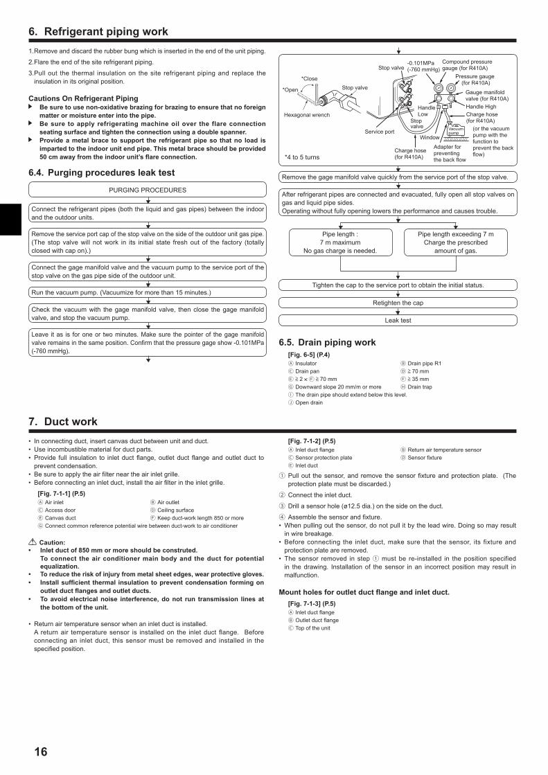
6.4. Purgingproceduresleaktest
PURGING PROCEDURES
Connect the refrigerant pipes (both the liquid and gas pipes) between the indoor and the outdoor units.
Remove the service port cap of the stop valve on the side of the outdoor unit gas pipe.(The stop valve will not work in its initial state fresh out of the factory (totally closed with cap on).)
Connect the gage manifold valve and the vacuum pump to the service port of the stop valve on the gas pipe side of the outdoor unit.
Run the vacuum pump. (Vacuumize for more than 15 minutes.)
Check the vacuum with the gage manifold valve, then close the gage manifold valve, and stop the vacuum pump.
Leave it as is for one or two minutes. Make sure the pointer of the gage manifold valve remains in the same position. Confirm that the pressure gage show -0.101MPa (-760 mmHg).
1. Remove and discard the rubber bung which is inserted in the end of the unit piping.
2. Flare the end of the site refrigerant piping.
3. Pull out the thermal insulation on the site refrigerant piping and replace the insulation in its original position.
CautionsOnRefrigerantPiping Besuretousenon-oxidativebrazingforbrazingtoensurethatnoforeignmatterormoistureenterintothepipe.
Besure toapply refrigeratingmachineoil over the flareconnectionseatingsurfaceandtightentheconnectionusingadoublespanner.
Provideametalbrace tosupport the refrigerantpipeso thatno load isimpartedtotheindoorunitendpipe.Thismetalbraceshouldbeprovided50cmawayfromtheindoorunit’sflareconnection.
Pipe length :7 m maximum
No gas charge is needed.
Pipe length exceeding 7 m Charge the prescribed
amount of gas.
Remove the gage manifold valve quickly from the service port of the stop valve.
After refrigerant pipes are connected and evacuated, fully open all stop valves on gas and liquid pipe sides.Operating without fully opening lowers the performance and causes trouble.
Hexagonal wrench
*4 to 5 turns
Stop valve
(or the vacuum pump with the function to prevent the back flow)
Gauge manifold valve (for R410A)
Pressure gauge (for R410A)
Compound pressure gauge (for R410A)
-0.101MPa (-760 mmHg)
Handle Low
Handle High
Window
Charge hose (for R410A)
Vacuum pump
Adapter for preventing the back flow
Charge hose (for R410A)
Service port
Stop valve
*Close
*Open Stop valve
Tighten the cap to the service port to obtain the initial status.
Retighten the cap
Leak test
6.5.Drainpipingwork[Fig.6-5](P.4) Insulator Drain pipe R1 Drain pan 70 mm 2 × 70 mm 35 mm Downward slope 20 mm/m or more Drain trap The drain pipe should extend below this level. Open drain
• In connecting duct, insert canvas duct between unit and duct.• Use incombustible material for duct parts.• Provide full insulation to inlet duct flange, outlet duct flange and outlet duct to
prevent condensation.• Be sure to apply the air filter near the air inlet grille.• Before connecting an inlet duct, install the air filter in the inlet grille.
[Fig.7-1-1](P.5) Air inlet Air outlet Access door Ceiling surface Canvas duct Keep duct-work length 850 or more Connect common reference potential wire between duct-work to air conditioner
Caution:• Inletductof850mmormoreshouldbeconstruted. Toconnect theair conditionermainbodyand theduct forpotential
equalization.• Toreducetheriskofinjuryfrommetalsheetedges,wearprotectivegloves.• Installsufficientthermal insulationtopreventcondensationformingon
outletductflangesandoutletducts.• Toavoidelectricalnoise interference,donot run transmission linesat
thebottomoftheunit.
• Return air temperature sensor when an inlet duct is installed. A return air temperature sensor is installed on the inlet duct flange. Before
connecting an inlet duct, this sensor must be removed and installed in the specified position.
7. Ductwork[Fig.7-1-2](P.5) Inlet duct flange Return air temperature sensor Sensor protection plate Sensor fixture Inlet duct
① Pull out the sensor, and remove the sensor fixture and protection plate. (The protection plate must be discarded.)
② Connect the inlet duct.
③ Drill a sensor hole (ø12.5 dia.) on the side on the duct.
④ Assemble the sensor and fixture.• When pulling out the sensor, do not pull it by the lead wire. Doing so may result
in wire breakage.• Before connecting the inlet duct, make sure that the sensor, its fixture and
protection plate are removed.• The sensor removed in step ① must be re-installed in the position specified
in the drawing. Installation of the sensor in an incorrect position may result in malfunction.
Mountholesforoutletductflangeandinletduct.[Fig.7-1-3](P.5) Inlet duct flange Outlet duct flange Top of the unit
17
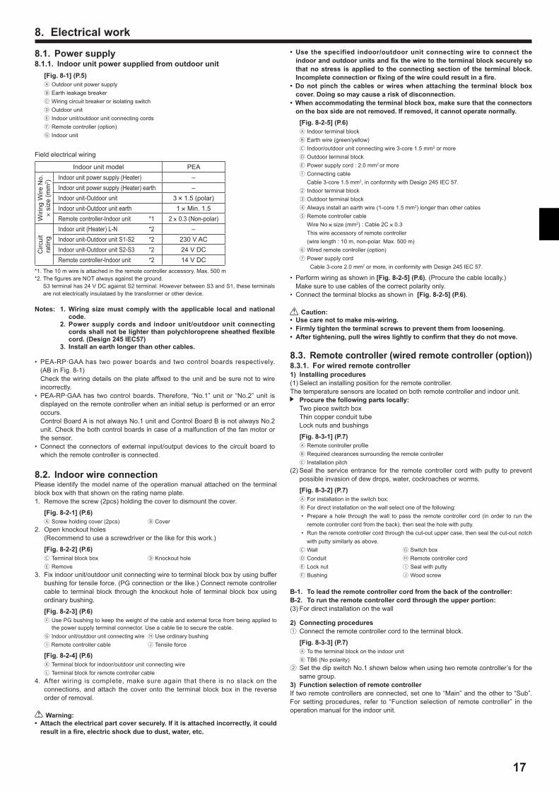
8.1. Powersupply8.1.1. Indoorunitpowersuppliedfromoutdoorunit
[Fig.8-1](P.5) Outdoor unit power supply Earth leakage breaker Wiring circuit breaker or isolating switch Outdoor unit Indoor unit/outdoor unit connecting cords Remote controller (option) Indoor unit
Field electrical wiring
Indoor unit model PEA
Wiri
ng W
ire N
o.
× si
ze (m
m2 ) Indoor unit power supply (Heater) –
Indoor unit power supply (Heater) earth –Indoor unit-Outdoor unit 3 × 1.5 (polar)Indoor unit-Outdoor unit earth 1 × Min. 1.5Remote controller-Indoor unit *1 2 × 0.3 (Non-polar)
Circ
uit
ratin
g
Indoor unit (Heater) L-N *2 –Indoor unit-Outdoor unit S1-S2 *2 230 V ACIndoor unit-Outdoor unit S2-S3 *2 24 V DCRemote controller-Indoor unit *2 14 V DC
*1. The 10 m wire is attached in the remote controller accessory. Max. 500 m*2. The figures are NOT always against the ground. S3 terminal has 24 V DC against S2 terminal. However between S3 and S1, these terminals
are not electrically insulataed by the transformer or other device.
Notes: 1.Wiringsizemust complywith theapplicable local andnationalcode.
2. Powersupplycordsand indoorunit/outdoorunit connectingcordsshallnotbelighterthanpolychloroprenesheathedflexiblecord.(Design245IEC57)
3. Installanearthlongerthanothercables.
• PEA-RP∙GAA has two power boards and two control boards respectively. (AB in Fig. 8-1)
Check the wiring details on the plate affixed to the unit and be sure not to wire incorrectly.
• PEA-RP∙GAA has two control boards. Therefore, “No.1” unit or “No.2” unit is displayed on the remote controller when an initial setup is performed or an error occurs.
Control Board A is not always No.1 unit and Control Board B is not always No.2 unit. Check the both control boards in case of a malfunction of the fan motor or the sensor.
• Connect the connectors of external input/output devices to the circuit board to which the remote controller is connected.
8. Electricalwork
8.2. IndoorwireconnectionPlease identify the model name of the operation manual attached on the terminal block box with that shown on the rating name plate.1. Remove the screw (2pcs) holding the cover to dismount the cover.
[Fig.8-2-1](P.6) Screw holding cover (2pcs) Cover
2. Open knockout holes (Recommend to use a screwdriver or the like for this work.)
[Fig.8-2-2](P.6) Terminal block box Knockout hole Remove
3. Fix indoor unit/outdoor unit connecting wire to terminal block box by using buffer bushing for tensile force. (PG connection or the like.) Connect remote controller cable to terminal block through the knockout hole of terminal block box using ordinary bushing.
[Fig.8-2-3](P.6) Use PG bushing to keep the weight of the cable and external force from being applied to
the power supply terminal connector. Use a cable tie to secure the cable. Indoor unit/outdoor unit connecting wire Use ordinary bushing Remote controller cable Tensile force
[Fig.8-2-4](P.6) Terminal block for indoor/outdoor unit connecting wire Terminal block for remote controller cable
4. After wiring is complete, make sure again that there is no slack on the connections, and attach the cover onto the terminal block box in the reverse order of removal.
Warning:• Attachtheelectricalpartcoversecurely.Ifitisattachedincorrectly,itcouldresultinafire,electricshockduetodust,water,etc.
• Use thespecified indoor/outdoorunit connectingwire toconnect theindoorandoutdoorunitsandfixthewiretotheterminalblocksecurelysothatnostress is applied to theconnectingsectionof the terminalblock.Incompleteconnectionorfixingofthewirecouldresultinafire.
• Donotpinch thecablesorwireswhenattaching the terminalblockboxcover.Doingsomaycauseariskofdisconnection.
•Whenaccommodatingtheterminalblockbox,makesurethattheconnectorsontheboxsidearenotremoved.Ifremoved,itcannotoperatenormally.[Fig.8-2-5](P.6) Indoor terminal block Earth wire (green/yellow) Indoor/outdoor unit connecting wire 3-core 1.5 mm2 or more Outdoor terminal block Power supply cord : 2.0 mm2 or more① Connecting cable Cable 3-core 1.5 mm2, in conformity with Design 245 IEC 57.② Indoor terminal block③ Outdoor terminal block④ Always install an earth wire (1-core 1.5 mm2) longer than other cables⑤ Remote controller cable Wire No × size (mm2) : Cable 2C × 0.3 This wire accessory of remote controller (wire length : 10 m, non-polar. Max. 500 m)⑥ Wired remote controller (option)⑦ Power supply cord Cable 3-core 2.0 mm2 or more, in conformity with Design 245 IEC 57.
• Perform wiring as shown in [Fig.8-2-5](P.6). (Procure the cable locally.) Make sure to use cables of the correct polarity only.• Connect the terminal blocks as shown in [Fig.8-2-5](P.6).
Caution:• Usecarenottomakemis-wiring.• Firmlytightentheterminalscrewstopreventthemfromloosening.• Aftertightening,pullthewireslightlytoconfirmthattheydonotmove.
8.3. Remotecontroller(wiredremotecontroller(option))8.3.1. Forwiredremotecontroller1) Installingprocedures(1) Select an installing position for the remote controller.The temperature sensors are located on both remote controller and indoor unit.
Procurethefollowingpartslocally: Two piece switch box Thin copper conduit tube Lock nuts and bushings
[Fig.8-3-1](P.7) Remote controller profile Required clearances surrounding the remote controller Installation pitch
(2) Seal the service entrance for the remote controller cord with putty to prevent possible invasion of dew drops, water, cockroaches or worms.
[Fig.8-3-2](P.7) For installation in the switch box: For direct installation on the wall select one of the following:• Prepare a hole through the wall to pass the remote controller cord (in order to run the
remote controller cord from the back), then seal the hole with putty.• Run the remote controller cord through the cut-out upper case, then seal the cut-out notch
with putty similarly as above. Wall Switch box Conduit Remote controller cord Lock nut Seal with putty Bushing Wood screw
B-1. Toleadtheremotecontrollercordfromthebackofthecontroller:B-2. Toruntheremotecontrollercordthroughtheupperportion:(3) For direct installation on the wall
2) Connectingprocedures① Connect the remote controller cord to the terminal block.
[Fig.8-3-3](P.7) To the terminal block on the indoor unit TB6 (No polarity)
② Set the dip switch No.1 shown below when using two remote controller’s for the same group.
3) FunctionselectionofremotecontrollerIf two remote controllers are connected, set one to “Main” and the other to “Sub”. For setting procedures, refer to “Function selection of remote controller” in the operation manual for the indoor unit.
18
8. Electricalwork
2) HowToInstall [Fig.8-4-2](P.8)to[Fig.8-4-9](P.9)1.Common items for “Installationon theceiling”and“Installationon the
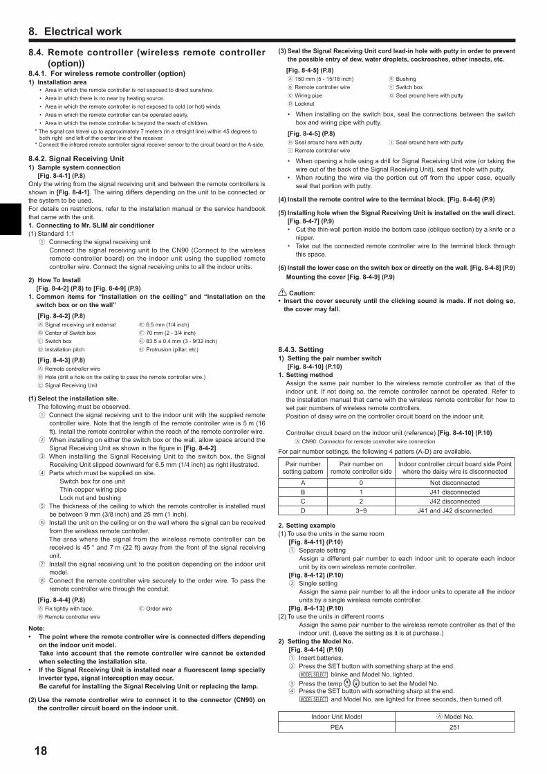
switchboxoronthewall”[Fig.8-4-2](P.8) Signal receiving unit external 6.5 mm (1/4 inch) Center of Switch box 70 mm (2 - 3/4 inch) Switch box 83.5 ± 0.4 mm (3 - 9/32 inch) Installation pitch Protrusion (pillar, etc)
[Fig.8-4-3](P.8) Remote controller wire Hole (drill a hole on the ceiling to pass the remote controller wire.) Signal Receiving Unit
(1)Selecttheinstallationsite. The following must be observed.① Connect the signal receiving unit to the indoor unit with the supplied remote
controller wire. Note that the length of the remote controller wire is 5 m (16 ft). Install the remote controller within the reach of the remote controller wire.
② When installing on either the switch box or the wall, allow space around the Signal Receiving Unit as shown in the figure in [Fig.8-4-2].
③ When installing the Signal Receiving Unit to the switch box, the Signal Receiving Unit slipped downward for 6.5 mm (1/4 inch) as right illustrated.
④ Parts which must be supplied on site.Switch box for one unitThin-copper wiring pipeLock nut and bushing
⑤ The thickness of the ceiling to which the remote controller is installed must be between 9 mm (3/8 inch) and 25 mm (1 inch).
⑥ Install the unit on the ceiling or on the wall where the signal can be received from the wireless remote controller.
The area where the signal from the wireless remote controller can be received is 45 ° and 7 m (22 ft) away from the front of the signal receiving unit.
⑦ Install the signal receiving unit to the position depending on the indoor unit model.
⑧ Connect the remote controller wire securely to the order wire. To pass the remote controller wire through the conduit.
[Fig.8-4-4](P.8) Fix tightly with tape. Order wire Remote controller wire
Note:• Thepointwheretheremotecontrollerwireisconnecteddiffersdepending
ontheindoorunitmodel. Take intoaccount that the remotecontrollerwirecannotbeextended
whenselectingtheinstallationsite.• lftheSignalReceivingUnitisinstallednearafluorescentlampspecially
invertertype,signalinterceptionmayoccur. BecarefulforinstallingtheSignalReceivingUnitorreplacingthelamp.
(2)Use the remotecontrollerwire toconnect it to theconnector (CN90)onthecontrollercircuitboardontheindoorunit.
(3)SealtheSignalReceivingUnitcordlead-inholewithputtyinordertopreventthepossibleentryofdew,waterdroplets,cockroaches,otherinsects,etc.
[Fig.8-4-5](P.8) 150 mm (5 - 15/16 inch) Bushing Remote controller wire Switch box Wiring pipe Seal around here with putty Locknut
• When installing on the switch box, seal the connections between the switch box and wiring pipe with putty.
[Fig.8-4-5](P.8) Seal around here with putty Seal around here with putty Remote controller wire
• When opening a hole using a drill for Signal Receiving Unit wire (or taking the wire out of the back of the Signal Receiving Unit), seal that hole with putty.
• When routing the wire via the portion cut off from the upper case, equally seal that portion with putty.
(4)Installtheremotecontrolwiretotheterminalblock.[Fig.8-4-6](P.9)
(5)InstallingholewhentheSignalReceivingUnitisinstalledonthewalldirect.[Fig.8-4-7](P.9)
• Cut the thin-wall portion inside the bottom case (oblique section) by a knife or a nipper.
• Take out the connected remote controller wire to the terminal block through this space.
(6)Installthelowercaseontheswitchboxordirectlyonthewall.[Fig.8-4-8](P.9) Mountingthecover[Fig.8-4-9](P.9)
Caution:• Insertthecoversecurelyuntiltheclickingsoundismade.Ifnotdoingso,thecovermayfall.
8.4.Remotecontroller (wireless remotecontroller(option))
8.4.1. Forwirelessremotecontroller(option)1) Installationarea
• Area in which the remote controller is not exposed to direct sunshine.• Area in which there is no near by heating source.• Area in which the remote controller is not exposed to cold (or hot) winds.• Area in which the remote controller can be operated easily.• Area in which the remote controller is beyond the reach of children.
* The signal can travel up to approximately 7 meters (in a streight line) within 45 degrees to both right and left of the center line of the receiver.
* Connect the infrared remote controller signal receiver sensor to the circuit board on the A-side.
8.4.2.SignalReceivingUnit1) Samplesystemconnection [Fig.8-4-1](P.8)Only the wiring from the signal receiving unit and between the remote controllers is shown in [Fig.8-4-1]. The wiring differs depending on the unit to be connected or the system to be used. For details on restrictions, refer to the installation manual or the service handbook that came with the unit.1.ConnectingtoMr.SLIMairconditioner(1) Standard 1:1① Connecting the signal receiving unit
Connect the signal receiving unit to the CN90 (Connect to the wireless remote controller board) on the indoor unit using the supplied remote controller wire. Connect the signal receiving units to all the indoor units.
2.Settingexample(1) To use the units in the same room
[Fig.8-4-11](P.10)① Separate setting
Assign a different pair number to each indoor unit to operate each indoor unit by its own wireless remote controller.
[Fig.8-4-12](P.10)② Single setting
Assign the same pair number to all the indoor units to operate all the indoor units by a single wireless remote controller.
[Fig.8-4-13](P.10)(2) To use the units in different rooms
Assign the same pair number to the wireless remote controller as that of the indoor unit. (Leave the setting as it is at purchase.)
2) SettingtheModelNo.[Fig.8-4-14](P.10)① Insert batteries.② Press the SET button with something sharp at the end. MODEL SELECT blinke and Model No. lighted.③ Press the temp button to set the Model No.④ Press the SET button with something sharp at the end. MODEL SELECT and Model No. are lighted for three seconds, then turned off.
Indoor Unit Model Model No.PEA 251
8.4.3.Setting1) Settingthepairnumberswitch [Fig.8-4-10](P.10)1.Settingmethod Assign the same pair number to the wireless remote controller as that of the
indoor unit. If not doing so, the remote controller cannot be operated. Refer to the installation manual that came with the wireless remote controller for how to set pair numbers of wireless remote controllers.
Position of daisy wire on the controller circuit board on the indoor unit.
Controller circuit board on the indoor unit (reference) [Fig.8-4-10](P.10) CN90: Connector for remote controller wire connection
For pair number settings, the following 4 patters (A-D) are available.
Pair number setting pattern
Pair number on remote controller side
Indoor controller circuit board side Point where the daisy wire is disconnected
A 0 Not disconnectedB 1 J41 disconnectedC 2 J42 disconnectedD 3~9 J41 and J42 disconnected
19
8.5. Functionsettings (Functionselectionvia theremotecontroller)
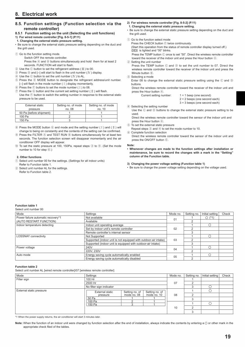
8.5.1 Functionsettingontheunit(Selectingtheunitfunctions)1) Forwiredremotecontroller[Fig.8-5-1](P.11)1.Changingtheexternalstaticpressuresetting.• Be sure to change the external static pressure setting depending on the duct and
the grill used.
① Go to the function setting mode. Switch OFF the remote controller. Press the and buttons simultaneously and hold them for at least 2
seconds. FUNCTION will start to flash.② Use the button to set the refrigerant address (Ⅲ ) to 00.③ Press and [--] will start to flash in the unit number (Ⅳ ) display.④ Use the button to set the unit number (Ⅳ ) to AL.⑤ Press the MODE button to designate the refrigerant address/unit number.
[--] will flash in the mode number (Ⅰ) display momentarily.⑥ Press the buttons to set the mode number (Ⅰ) to 08.⑦ Press the button and the current set setting number (Ⅱ ) will flash. Use the button to switch the setting number in response to the external static
pressure to be used.
External static pressure
Setting no. of mode no. 08
Setting no. of mode no. 10
50 Pa (before shipment) 1 1100 Pa 2 1150 Pa 3 1
⑧ Press the MODE button and mode and the setting number (Ⅰ) and (Ⅱ ) will change to being on constantly and the contents of the setting can be confirmed.
⑨ Press the FILTER and TEST RUN buttons simultaneously for at least two seconds. The function selection screen will disappear momentarily and the air conditioner OFF display will appear.
⑩ To set the static pressure at 100, 150Pa, repeat steps ③ to ⑨. (Set the mode number to 10 for step ⑥.)
2.Otherfunctions①Select unit number 00 for the settings. (Settings for all indoor units) Refer to Function table 1.② Select unit number AL for the settings. Refer to Function table 2.
8. Electricalwork2) Forwirelessremotecontroller[Fig.8-5-2](P.11)1.Changingtheexternalstaticpressuresetting.• Be sure to change the external static pressure setting depending on the duct and
the grill used.
① Go to the function select mode Press the CHECK button twice continuously. (Start this operation from the status of remote controller display turned off.) CHECK is lighted and “00” blinks.
Press the TEMP button once to set “50”. Direct the wireless remote controller toward the receiver of the indoor unit and press the Hour button .
② Setting the unit numberPress the TEMP button and to set the unit number to 07. Direct the wireless remote controller toward the receiver of the indoor unit and press the Minute button .
③ Selecting a mode Enter 08 to change the external static pressure setting using the and
buttons.Direct the wireless remote controller toward the receiver of the indoor unit and press the Hour button .
Current setting number: 1 = 1 beep (one second) 2 = 2 beeps (one second each) 3 = 3 beeps (one second each)④ Selecting the setting number Use the and buttons to change the external static pressure setting to be
used. Direct the wireless remote controller toward the sensor of the indoor unit and
press the Hour button .⑤ To set the external static pressure Repeat steps ③ and ④ to set the mode number to 10.⑥ Complete function selection
Direct the wireless remote controller toward the sensor of the indoor unit and press the ON/OFF button .
Note:• Wheneverchangesaremade to the functionsettingsafter installationormaintenance,besure to record thechangeswithamark in the“Setting”columnoftheFunctiontable.
3) Changingthepowervoltagesetting(Functiontable1)• Be sure to change the power voltage setting depending on the voltage used.
Functiontable1Select unit number 00Mode Settings Mode no. Setting no. Initial setting CheckPower failure automatic recovery*1(AUTO RESTART FUNCTION)
Not available 01 1 (*1)Available 2
Indoor temperature detecting Indoor unit operating average02
1Set by indoor unit’s remote controller 2Remote controller’s internal sensor 3
LOSSNAY connectivity Not Supported03
1Supported (indoor unit is not equipped with outdoor-air intake) 2Supported (indoor unit is equipped with outdoor-air intake) 3
Power voltage 240V 04 1220V, 230V 2
Auto mode Energy saving cycle automatically enabled 05 1Energy saving cycle automatically disabled 2
Functiontable2Select unit number AL [wired remote controller]/07 [wireless remote controller]
Mode Settings Mode no. Setting no. Initial setting CheckFilter sign 100 Hr
071
2500 Hr 2No filter sign indicator 3
External static pressure External static pressure
Setting no. of mode no. 08
Setting no. of mode no. 10
50 Pa 1 1100 Pa 2 1150 Pa 3 1
08123
10123
*1 When the power supply returns, the air conditioner will start 3 minutes later.
Note: When the function of an indoor unit were changed by function selection after the end of installation, always indicate the contents by entering a or other mark in the appropriate check filed of the tables.

20
9.1.Beforetestrun Aftercompleting installationandthewiringandpipingof the indoorandoutdoorunits,checkforrefrigerantleakage,loosenessinthepowersupplyorcontrolwiring,wrongpolarity,andnodisconnectionofonephaseinthesupply.
Usea500-voltmegohmmeter tocheck that the resistancebetween thepowersupplyterminalsandgroundisatleast1.0MΩ.
Donot carryout this teston thecontrolwiring (lowvoltagecircuit)terminals.Warning:
Donotusetheairconditioneriftheinsulationresistanceislessthan1.0MΩ.InsulationresistanceAfter installation or after the power source to the unit has been cut for an extended period, the insulation resistance will drop below 1 MΩ due to refrigerant accumulating in the compressor. This is not a malfunction. Perform the following procedures.1. Remove the wires from the compressor and measure the insulation resistance
of the compressor.2. If the insulation resistance is below 1 MΩ, the compressor is faulty or the
resistance dropped due the accumulation of refrigerant in the compressor.3. After connecting the wires to the compressor, the compressor will start to warm
up after power is supplied. After supplying power for the times indicated below, measure the insulation resistance again.
• The insulation resistance drops due to accumulation of refrigerant in the compressor. The resistance will rise above 1 MΩ after the compressor is warmed up for two to three hours.
(The time necessary to warm up the compressor varies according to atmospheric conditions and refrigerant accumulation.)
• To operate the compressor with refrigerant accumulated in the compressor, the compressor must be warmed up at least 12 hours to prevent breakdown.
4. If the insulation resistance rises above 1 MΩ, the compressor is not faulty.
Caution:• Thecompressorwillnotoperateunlessthepowersupplyphaseconnectioniscorrect.
• Turnonthepoweratleast12hoursbeforestartingoperation.- Starting operation immediately after turning on the main power switch can result
in severe damage to internal parts. Keep the power switch turned on during the operational season.
9. Testrun
9.2. Testrun9.2.1. Usingwiredremotecontroller(option)① Turn on the power at least 12 hours before the test run.② Press the [TEST] button twice. “TEST RUN” liquid crystal display③ Press the [Mode selection] button. Make sure that wind is blown out.④ Press the [Mode selection] button and switch to the cooling (or heating) mode. Make sure that cold (or warm) wind is blown out.⑤ Press the [Fan speed] button. Make sure that the wind speed is switched.⑥ Check operation of the outdoor unit fan.⑦ Release test run by pressing the [ON/OFF] button. Stop⑧ Register a telephone number. The telephone number of the repair shop, sales office, etc., to contact if an
error occurs can be registered in the remote controller. The telephone number will be displayed when an error occurs. For registration procedures, refer to the operation manual for the indoor unit.
[Fig.9-2-1](P.11) ON/OFF button Test run display Indoor temperature liquid line temperature display ON/OFF lamp Power display Error code display Test run remaining time display Set temperature button Mode selection button Fan speed button TEST button
9.2.2. Wiredremotecontroller① Turn on the power.② Press the [CHECK] button twice.③ Set refrigerant address with [TEMP] button if system control is used.④ Press the [ON/OFF] button to stop the self-check.
[Fig.9-2-2](P.11) CHECK button Refrigerant address TEMP. button IC: Indoor unit
OC: Outdoor unit Check code
• For description of each check code, refer to the following table.
① Check code Symptom RemarkP1 Intake sensor error
Each unit has two each of the following: intake sensors, liquid p ipe sensors , 2 -phase p ipe sensors, and fan motors. When a problem occurs with one of any of the items above, an error code (P1, P2, P8, P9, or PB) will appear. When an error code appears, check both of the items.
P2, P9 Pipe (Liquid or 2-phase pipe) sensor errorE6, E7 Indoor/outdoor unit communication errorP4 Drain sensor errorP5 Drain pump errorPA Forced compressor errorPB Fan motor errorP6 Freezing/Overheating safeguard operationEE Communication error between indoor and outdoor unitsP8 Pipe temperature errorE4 Remote controller signal receiving errorFb Indoor unit control system error (memory error, etc.)E0, E3 Remote controller transmission errorE1, E2 Remote controller control board errorE9 Indoor/outdoor unit communication error (Transmitting error) (Outdoor unit)
For details, check the LED display of the outdoor controller board.
UP Compressor overcurrent interruptionU3, U4 Open/short of outdoor unit thermistorsUF Compressor overcurrent interruption (When compressor locked)U2 Abnormal high discharging temperature/49C worked/insufficient refrigerantU1, Ud Abnormal high pressure (63H worked)/Overheating safeguard operationU5 Abnormal temperature of heat sinkU8 Outdoor unit fan safeguard stopU6 Compressor overcurrent interruption/Abnormal of power moduleU7 Abnormality of super heat due to low discharge temperatureU9, UH Abnormality such as overvoltage or voltage shortage and abnormal synchronous signal to main circuit/
Current sensor errorOthers Other errors (Refer to the technical manual for the outdoor unit.)
• On wired remote controller① Check code displayed in the LCD.

21
9. Testrun
• If the unit cannot be operated properly after the above test run has been performed, refer to the following table to remove the cause.Symptom
CauseWired remote controller LED 1, 2 (PCB in outdoor unit)
PLEASE WAITFor about 2 minutes following power-on
After LED 1, 2 are lighted, LED 2 is turned off, then only LED 1 is lighted. (Correct operation)
• For about 2 minutes after power-on, operation of the remote controller is not possible due to system start-up. (Correct operation)
PLEASE WAIT → Error codeAfter about 2 minutes has expired following power-on
Only LED 1 is lighted. → LED 1, 2 blink.
• Connector for the outdoor unit’s protection device is not connected.
• Reverse or open phase wiring for the outdoor unit’s power terminal block (L1, L2, L3)
Display messages do not appear even when operation switch is turned ON (operation lamp does not light up).
Only LED 1 is lighted. → LED 1, 2 blinks twice, LED 2 blinks once.
• Incorrect wiring between indoor and outdoor units (incorrect polarity of S1, S2, S3)
• Remote controller wire short
[Output pattern B] Errors detected by unit other than indoor unit (outdoor unit, etc.)Wireless remote controller
Symptom RemarkBeeper sounds/OPERATION INDICATOR lamp flashes (Number of times)
1 Indoor/outdoor unit communication error (Transmitting error) (Outdoor unit)
For details, check the LED display of the outdoor controller board.
2 Compressor overcurrent interruption3 Open/short of outdoor unit thermistors4 Compressor overcurrent interruption (When compressor locked)5 Abnormal high discharging temperature/49C worked/ insufficient refrigerant6 Abnormal high pressure (63H worked)/ Overheating safeguard operation7 Abnormal temperature of heat sink8 Outdoor unit fan protection stop9 Compressor overcurrent interruption/Abnormal of power module10 Abnormality of super heat due to low discharge temperature
11 Abnormality such as overvoltage or voltage shortage and abnormal synchronous signal to main circuit/Current sensor error
12 –13 –14 Other errors (Refer to the technical manual for the outdoor unit.)
*1Ifthebeeperdoesnotsoundagainaftertheinitialtwobeepstoconfirmtheself-checkstartsignalwasreceivedandtheOPERATIONINDICATORlampdoesnotcomeon,therearenoerrorrecords.
*2Ifthebeepersoundsthreetimescontinuously“beep,beep,beep(0.4+0.4+0.4sec.)”aftertheinitialtwobeepstoconfirmtheself-checkstartsignalwasreceived,thespecifiedrefrigerantaddressisincorrect.
• On wireless remote controller The continuous buzzer sounds from receiving section of indoor unit. Blink of operation lamp• On wired remote controller Check code displayed on the LCD.• Check that all LEDs on the two control boards on the indoor unit are lit or blinking (3 each, 6 total).
9.3. Testrun9.3.1. Usingwirelessremotecontroller(option)
[Fig.9-3](P.11)①Turn on the power to the unit at least 12 hours before the test run.② Press the TEST RUN button twice continuously. (Start this operation from the status of remote controller display turned off.) TEST RUN and current operation mode are displayed.③ Press the MODE button to activate COOL mode, then check whether cool
air is blown out from the unit.
④ Press the MODE button to activate HEAT mode, then check whether warm air is blown out from the unit.
⑤ Press the FAN button and check whether fan speed changes.⑥ Press the VANE button and check whether the auto vane operates properly.⑦ Press the ON/OFF button to stop the test run.
Note:• Point the remotecontroller towards the indoorunit receiverwhile
followingsteps②to⑦.• ItisnotpossibletoruntheinFAN,DRYorAUTOmode.
[Output pattern A] Errors detected by indoor unit
Wireless remote controller Wired remote controller
Symptom RemarkBeeper sounds/OPERATION INDICATOR lamp flashes
(Number of times)Check code
1 P1 Intake sensor error2 P2, P9 Pipe (Liquid or 2-phase pipe) sensor error3 E6, E7 Indoor/outdoor unit communication error4 P4 Drain sensor error5 P5 Drain pump error6 P6 Freezing/Overheating safeguard operation7 EE Communication error between indoor and outdoor units8 P8 Pipe temperature error9 E4 Remote controller signal receiving error10 – –11 PB Fan motor error12 Fb Indoor unit control system error (memory error, etc.)
No sound – – No corresponding

22
10.Maintenance
10.1. Gascharge[Fig.10-1](P.12) Indoor unitUnionLiquid pipeGas pipeStop valveOutdoor unitRefrigerant gas cylinder operating valveRefrigerant gas cylinder for R410A with siphonRefrigerant (liquid)Electronic scale for refrigerant chargingCharge hose (for R410A)Gauge manifold valve (for R410A)Service port
1. Connectgascylindertotheserviceportofstopvalve(3-way).2. Executeairpurgeof thepipe (orhose) coming from refrigerantgas
cylinder.3. Replenish specified amount of refrigerant,while running the air
conditionerforcooling.
Note:In case of adding refrigerant, comply with the quantity specified for the refrigerating cycle.
Caution:• Donotdischargetherefrigerantintotheatmosphere. Take carenot todischarge refrigerant into the atmosphereduringinstallation,reinstallation,orrepairstotherefrigerantcircuit.
• Foradditionalcharging,chargetherefrigerantfromliquidphaseofthegascylinder.
Iftherefrigerantischargedfromthegasphase,compositionchangemayoccur in the refrigerant inside thecylinderand theoutdoorunit. In thiscase,abilityoftherefrigeratingcycledecreasesornormaloperationcanbeimpossible.However,chargingtheliquidrefrigerantallatoncemaycausethecompressortobelocked.Thus,chargetherefrigerantslowly.
To maintain the high pressure of the gas cylinder, warm the gas cylinder with warm water (under 40°C) during cold season. But never use naked fire or steam.
9. Testrun
For description of each LED (LED1, 2, 3) provided on the indoor controller, refer to the following table.
LED 1 (power for microcomputer) Indicates whether control power is supplied. Make sure that this LED is always lit.LED 2 (power for remote controller) Indicates whether power is supplied to the remote controller. This LED lights only in the case of
the indoor unit which is connected to the outdoor unit refrigerant address “0”. LED 3 (communication between indoor and outdoor units) Indicates state of communication between the indoor and outdoor units. Make sure that this LED is
always blinking.
9.4.AUTORESTARTFUNCTIONIndoorcontrollerboardThis model is equipped with the AUTO RESTART FUNCTION.When the indoor unit is controlled with the remote controller, the operation mode, set temperature, and the fan speed are memorized by the indoor controller board.The auto restart function sets to work the moment the power has restored after power failure, then, the unit will restart automatically.Set the AUTO RESTART FUNCTION using the remote controller. (Mode no.01)
On the wireless remote controller with conditions above, following phenomena takes place.• No signals from the remote controller are accepted.• OPE lamp is blinking.• The buzzer makes a short ping sound.
Note:Operationisnotpossibleforabout30secondsaftercancellationoffunctionselection.(Correctoperation)
11.Specifications
Model PEA-RP100GAA PEA-RP125, 140GAAPower input kW 0.21 0.49Current A 1.83 3.84
Air flow rate(Hi-Lo)
50Pam3/min 42-34
60-48100Pa 54-43150Pa 52-41
Sound level at 50Pa(Hi-Lo)
dB(A) 42-39 45-42
Weight kg 63 63


Please be sure to put the contact address/telephone number on this manual before handing it to the customer.
HEAD OFFICE: TOKYO BLDG., 2-7-3, MARUNOUCHI, CHIYODA-KU, TOKYO 100-8310, JAPAN
KD79M111H02