pe and px electronic trip circuit breakers with micrologic ... · instruction manual, may cause...
TRANSCRIPT
Instruction Bulletin48040-940-03
03/01Cedar Rapids, IA, USA
K279
PE and PX Electronic Trip Circuit Breakerswith MICROLOGIC® Trip SystemSeries 6B
Retain for future use.

PE and PX Electronic Trip Circuit Breakers with MICROLOGIC® Trip System Bulletin No. 48040-940-0303/01
© 1998–2001 Schneider Electric All Rights Reserved2
The addition of either symbol to a “Danger” or “Warning” safety label indicates that an electrical hazard exists which will result in personal injury if the instructions are not followed.
This is the safety alert symbol. It is used to alert you to potential personal injury hazards. Obey all safety messages that follow this symbol to avoid possible injury or death.
NOTE: Provides additional information to clarify or simplify a procedure.
Electrical equipment should be serviced only by qualified personnel. No responsibility is assumed by Schneider Electric for any consequences arising out of the use of this material. This document is not intended as an instruction manual for untrained persons.
This equipment has been tested and found to comply with the limits for a Class A digital device, pursuant to part 15 of the FCC Rules. These limits are designed to provide reasonable protection against harmful interference when the equipment is operated in a commercial environment. This equipment generates, uses, and can radiate radio frequency energy and, if not installed and used in accordance with the instruction manual, may cause harmful interference to radio communications. Operation of this equipment in a residential area is likely to cause harmful interference in which case the user will be required to correct the interference at his own expense.
DANGER!
DANGER indicates an imminently hazardous situation which, if not avoided, will result in death or serious injury.
WARNING!WARNING indicates a potentially hazardous situation which, if not avoided, can result in death or serious injury.
CAUTION!CAUTION indicates a potentially hazardous situation which, if not avoided, can result in minor or moderate injury.
hazardous situation which, if not avoided, can result in property damage.CAUTION, used without the safety alert symbol, indicates a potentially
CAUTION
NOTICERead these instructions carefully and look at the equipment to become familiar with the device before trying to install, operate, service or maintain it. The following special messages may appear throughout this bulletin or on the equipment to warn of potential hazards or to call attention to information that clarifies or simplifies a procedure.
PLEASE NOTE:
FCC NOTICE:
�
3©1998– 2001 Schneider Electric All Rights Reserved
Bulletin No. 48040-940-03 PE and PX Electronic Trip Circuit Breakers with MICROLOGIC® Trip System03/01 Table of Contents
Section 1—General Information .................................................................. 5Identification........................................................................................... 5Sensor.................................................................................................... 5Frame Size............................................................................................. 5Interrupting Ratings................................................................................ 5Circuit Breakers Rated 100%................................................................. 5Accessories and Control Wiring............................................................. 6Terminal Pads........................................................................................ 6Receving Inspection............................................................................... 6
Section 2—Installation and Removal........................................................... 7600–1600 A PE and 600–2000 A PX Circuit Breaker Installation.......... 7
Cable Connections........................................................................... 7Bus Bar Connections ....................................................................... 8
1800–2500 A PE and 2500 A PX Circuit Breaker Installation.............. 10Circuit Breaker Removal ...................................................................... 15
Section 3—Trip Unit Operation.................................................................. 16Current Rating...................................................................................... 16Ammeter/Trip Indicator ........................................................................ 17Memory Feature................................................................................... 17Ground-Fault Detection........................................................................ 17Trip Characteristics .............................................................................. 18Standard Trip Unit Functions ............................................................... 19
Long-time Trip Function ................................................................. 19Short-time Trip Function ...................................................................... 19Instantaneous Trip Function ................................................................ 20Ground-fault Trip Function................................................................... 20Full-Function Trip Unit Function........................................................... 21Long-time Trip Function....................................................................... 21Short-time Trip Function ...................................................................... 21Instantaneous Trip Function ................................................................ 22Ground-fault Trip Function................................................................... 22Ground-fault Alarm Function................................................................ 22
Section 4—Trip Unit Adjustments and Control Wiring............................... 23Trip Unit Adjustment ............................................................................ 23Control Wiring ...................................................................................... 24Terminal Location ................................................................................ 24Circuit Breaker Accessories................................................................. 24Ground-fault Protection or Ground-fault Alarm .................................... 25POWERLOGIC® System (PE Circuit Breaker Only) ........................... 26Zone-selective Interlocking (PE Circuit Breaker Only)......................... 26Route Control Wiring............................................................................ 28Test Ground-fault Feature.................................................................... 28Check Installation................................................................................. 29Seal Trip Unit ....................................................................................... 30
Section 5—Accessories............................................................................. 31Shunt Trip ............................................................................................ 31Undervoltage Trip ................................................................................ 31Auxiliary Switch.................................................................................... 31Alarm Switch........................................................................................ 32Communications Adapter
(PE Circuit Breaker Only).............................................................. 32Restraint Interface Module
(PE Circuit Breaker Only).............................................................. 32Universal Test Set................................................................................ 33Trip Indicator ........................................................................................ 33Ammeter/Trip Indicator ........................................................................ 34
Section 6—Troubleshooting ...................................................................... 35Appendix A—Parts Lists............................................................................ 36
Table of Contents
© 1998–2001 Schneider Electric All Rights Reserved4
PE and PX Electronic Trip Circuit Breakers with MICROLOGIC® Trip System Bulletin No. 48040-940-03Table of Contents 03/01
Circuit Breaker with Terminal Pads...................................................... 36600–1600 A PE and 600–2000 A PX Circuit Breakers................... 36
Circuit Breaker with Terminal Pads...................................................... 371800–2500 A PE and 2500 A PX Circuit Breakers......................... 37
Circuit Breaker with Terminal Pads...................................................... 381800–2500 A PE and 2500 A PX Circuit Breakers......................... 38
Catalog Numbers ................................................................................. 39Appendix B—Dimensional Drawings ......................................................... 40
Neutral Current Transformer ................................................................ 40Circuit Breaker Dimensions..................................................................41Circuit Breaker with Terminal Pads...................................................... 42
600–1600 A PE and 600–2000 A PX Circuit Breakers................... 42Circuit Breaker with Terminal Pads...................................................... 43
1800–2500 A PE and 2500 A PX Circuit Breakers......................... 43Terminal Pad Bus (PALTB) Dimensions .............................................. 44
600–1600 A PE and 600-2000 A PX Circuit Breakers ................... 44Terminal Pad Bus (PALTB) Dimensions .............................................. 45
1800–2500 A PE and 2500 A PX Circuit Breakers......................... 45Appendix C—Wiring Diagrams ..................................................................46
Shunt Trip............................................................................................. 46Undervoltage Trip................................................................................. 46Auxiliary Switch .................................................................................... 46Alarm Switch ........................................................................................46Ground-fault System ............................................................................ 47Zone-selective Interlocking
(PE Circuit Breaker Only) .............................................................. 48Glossary of Terms and Acronyms.............................................................. 49Index .......................................................................................................... 54

Bulletin No. 48040-940-03 PE and PX Electronic Trip Circuit Breakers with MICROLOGIC® Trip System03/01 Section 1—General Information
5© 1998–2001 Schneider Electric All Rights Reserved
PE and PX circuit breakers with MICROLOGIC® Trip Systems conform to UL, CSA and IEC standards for electronic trip molded case circuit breakers. They provide adjustable tripping functions and characteristics on ac systems. PE and PX circuit breakers are not applicable for use on dc systems.
The circuit breaker sensor size is the maximum current rating possible for a specific circuit breaker. It is based on the size of the current sensor inside the circuit breaker. (Current sensors are integral to the circuit breaker and cannot be removed or replaced.) PE and PX circuit breaker sensors are available in four sizes: 1200, 1600, 2000 and 2500 amperes.
The maximum current rating a circuit breaker family can carry is called the frame size. All PE and PX circuit breakers have a 2500 A frame size and are the same physical size.
The maximum amount of current the circuit breaker is designed to safely interrupt is called the interrupting rating. Interrupting ratings are shown on the faceplate (A) of the circuit breaker.
Figure 1: Interrupting Ratings
PE circuit breakers, except 2500 A, are 100% rated. Circuit breakers marked "100% Rated" can be continuously loaded to 100% of their rating as long as conditions marked on the circuit breaker case are met.
These conditions include conductor specifications and an enclosure size of at least 45 x 36 x 24 in. (1143 x 914 x 610 mm) with a minimum 37 sq. in. (23,871 mm2) of ventilation on the top and 66 sq. in. (42,581 mm2) of ventilation on the bottom of the enclosure. This marking does not prohibit using these circuit breakers in applications requiring only 80% continuous loading.
Section 1—General Information
IDENTIFICATION
SENSOR
FRAME SIZE
INTERRUPTING RATINGS
A
0677
3002
CIRCUIT BREAKERS RATED 100%
PE and PX Electronic Trip Circuit Breakers with MICROLOGIC® Trip System Bulletin No. 48040-940-03Section 1—General Information 03/01
© 1998–2001 Schneider Electric All Rights Reserved6
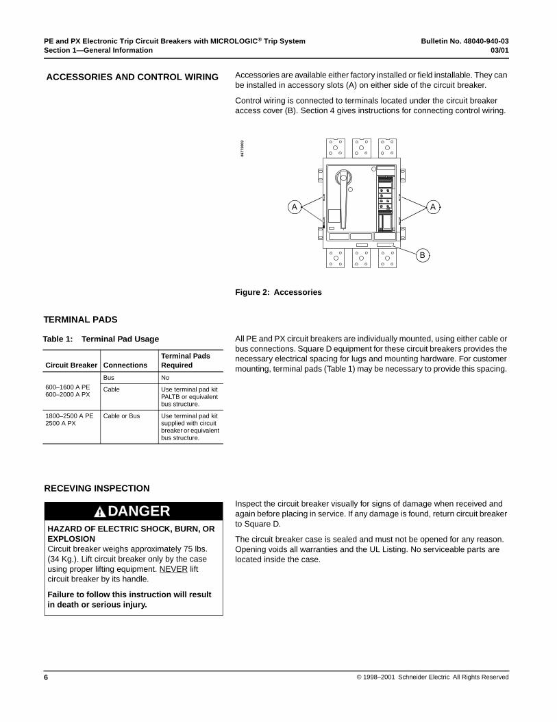
Accessories are available either factory installed or field installable. They can be installed in accessory slots (A) on either side of the circuit breaker.
Control wiring is connected to terminals located under the circuit breaker access cover (B). Section 4 gives instructions for connecting control wiring.
Figure 2: Accessories
All PE and PX circuit breakers are individually mounted, using either cable or bus connections. Square D equipment for these circuit breakers provides the necessary electrical spacing for lugs and mounting hardware. For customer mounting, terminal pads (Table 1) may be necessary to provide this spacing.
Inspect the circuit breaker visually for signs of damage when received and again before placing in service. If any damage is found, return circuit breaker to Square D.
The circuit breaker case is sealed and must not be opened for any reason. Opening voids all warranties and the UL Listing. No serviceable parts are located inside the case.
ACCESSORIES AND CONTROL WIRING
A A
B
0677
3003
TERMINAL PADS
Table 1: Terminal Pad Usage
Circuit Breaker ConnectionsTerminal PadsRequired
600–1600 A PE600–2000 A PX
Bus No
Cable Use terminal pad kit PALTB or equivalent bus structure.
1800–2500 A PE2500 A PX
Cable or Bus Use terminal pad kit supplied with circuit breaker or equivalent bus structure.
RECEVING INSPECTION
HAZARD OF ELECTRIC SHOCK, BURN, OR EXPLOSIONCircuit breaker weighs approximately 75 lbs. (34 Kg.). Lift circuit breaker only by the case using proper lifting equipment. NEVER lift circuit breaker by its handle.
Failure to follow this instruction will result in death or serious injury.
DANGER
Bulletin No. 48040-940-03 PE and PX Electronic Trip Circuit Breakers with MICROLOGIC® Trip System03/01 Section 2—Installation and Removal
7© 1998–2001 Schneider Electric All Rights Reserved
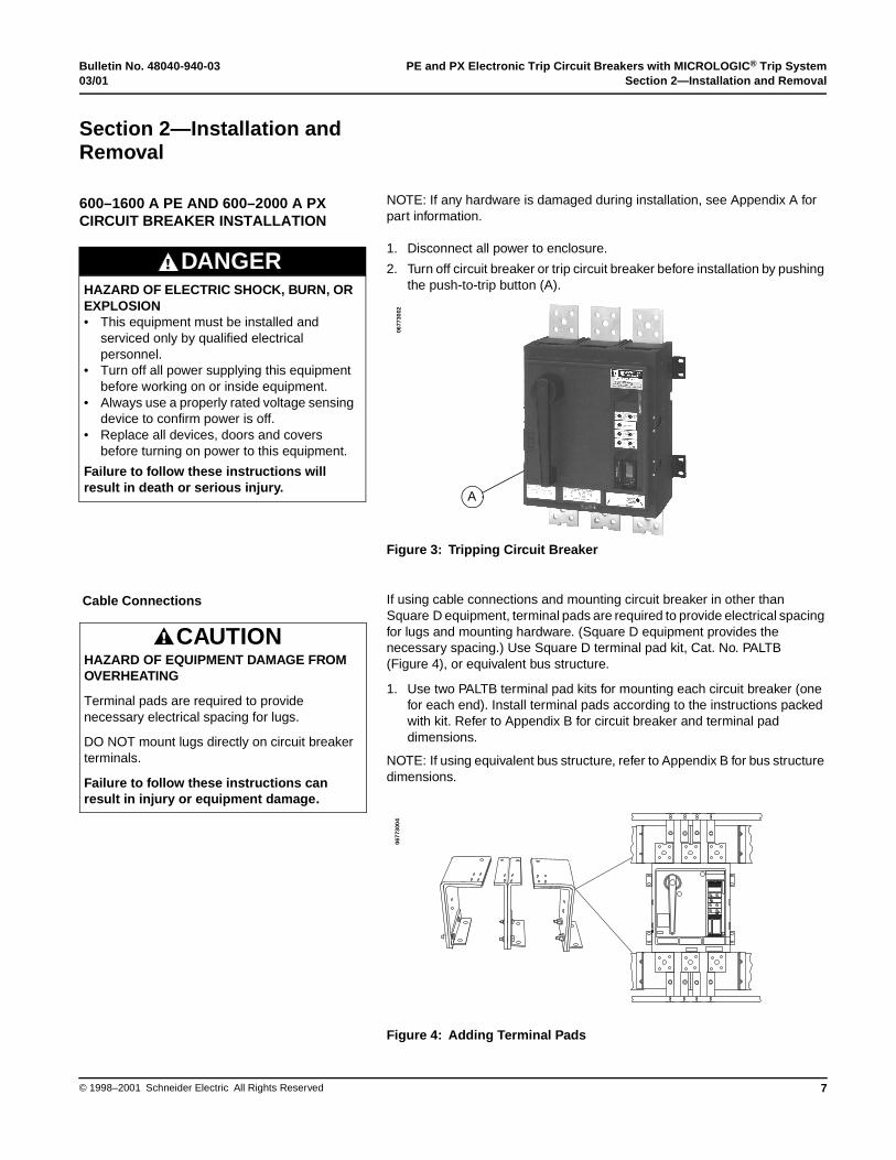
NOTE: If any hardware is damaged during installation, see Appendix A for part information.
1. Disconnect all power to enclosure.
2. Turn off circuit breaker or trip circuit breaker before installation by pushing the push-to-trip button (A).
Figure 3: Tripping Circuit Breaker
If using cable connections and mounting circuit breaker in other than Square D equipment, terminal pads are required to provide electrical spacing for lugs and mounting hardware. (Square D equipment provides the necessary spacing.) Use Square D terminal pad kit, Cat. No. PALTB (Figure 4), or equivalent bus structure.
1. Use two PALTB terminal pad kits for mounting each circuit breaker (one for each end). Install terminal pads according to the instructions packed with kit. Refer to Appendix B for circuit breaker and terminal pad dimensions.
NOTE: If using equivalent bus structure, refer to Appendix B for bus structure dimensions.
Figure 4: Adding Terminal Pads
Section 2—Installation and Removal
600–1600 A PE AND 600–2000 A PX CIRCUIT BREAKER INSTALLATION
HAZARD OF ELECTRIC SHOCK, BURN, OR EXPLOSION• This equipment must be installed and
serviced only by qualified electrical personnel.
• Turn off all power supplying this equipment before working on or inside equipment.
• Always use a properly rated voltage sensing device to confirm power is off.
• Replace all devices, doors and covers before turning on power to this equipment.
Failure to follow these instructions will result in death or serious injury.
DANGER
A
0677
3002
Cable Connections
HAZARD OF EQUIPMENT DAMAGE FROM OVERHEATING
Terminal pads are required to provide necessary electrical spacing for lugs.
DO NOT mount lugs directly on circuit breaker terminals.
Failure to follow these instructions can result in injury or equipment damage.
CAUTION
0677
3004

PE and PX Electronic Trip Circuit Breakers with MICROLOGIC® Trip System Bulletin No. 48040-940-03Section 2—Installation and Removal 03/01
© 1998–2001 Schneider Electric All Rights Reserved8
2. Install lugs and conductors:
Figure 5: Adding Lugs
Each terminal pad has three holes, and can mount up to three pairs of lugs. Acceptable lugs and wire ranges are indicated in Table 2. Install lugs and cables as directed in lug kit instructions.
Distribute conductors evenly on each side of each connector. The number of conductors on one side of a terminal pad must not exceed that on the opposite side by more than one. Mount AL2500PA lugs in pairs, even if one lug is not used, to assure proper hardware tightening. See Figure 5. Lugs can be rotated 180 degrees from position shown.
NOTE: Conductors running behind the circuit breaker must not be any closer to circuit breaker case than 1-1/2 in. (38 mm) from circuit breaker base.
1. If using bus bar connections and mounting circuit breaker in other than Square D equipment, check circuit breaker mounting hole pattern of bus.
2. Clean contact surfaces of circuit breaker terminals and terminal pads or bus bars using a nonabrasive cleaner. (An abrasive cleaner can remove plating, resulting in joint deterioration.)
Figure 6: Mounting Hole Pattern of Bus
0677
3005
Table 2: Lug Data
Cat. Number
Conductors
No. Size1
AL2500PA 12
1/0 AWG–750 kcmil (50–400 mm2)1/0 AWG–300 kcmil (50–150 mm2)
VC2500PA7 1 500–750 kcmil (240–400 mm2)
VC2500PA7 1 2/0 AWG–500 kcmil (70–240 mm2)
1 Conductor sizes apply to both aluminum and copper conductors.
Bus Bar Connections
1.50[38]
1.50[38]
1.50[38]
4.00[102]
Dia.
17[432]
4.00[102]
24 Places
0.44[11]
0677
3006
Dimensions: in.[mm]
Bulletin No. 48040-940-03 PE and PX Electronic Trip Circuit Breakers with MICROLOGIC® Trip System03/01 Section 2—Installation and Removal
9© 1998–2001 Schneider Electric All Rights Reserved
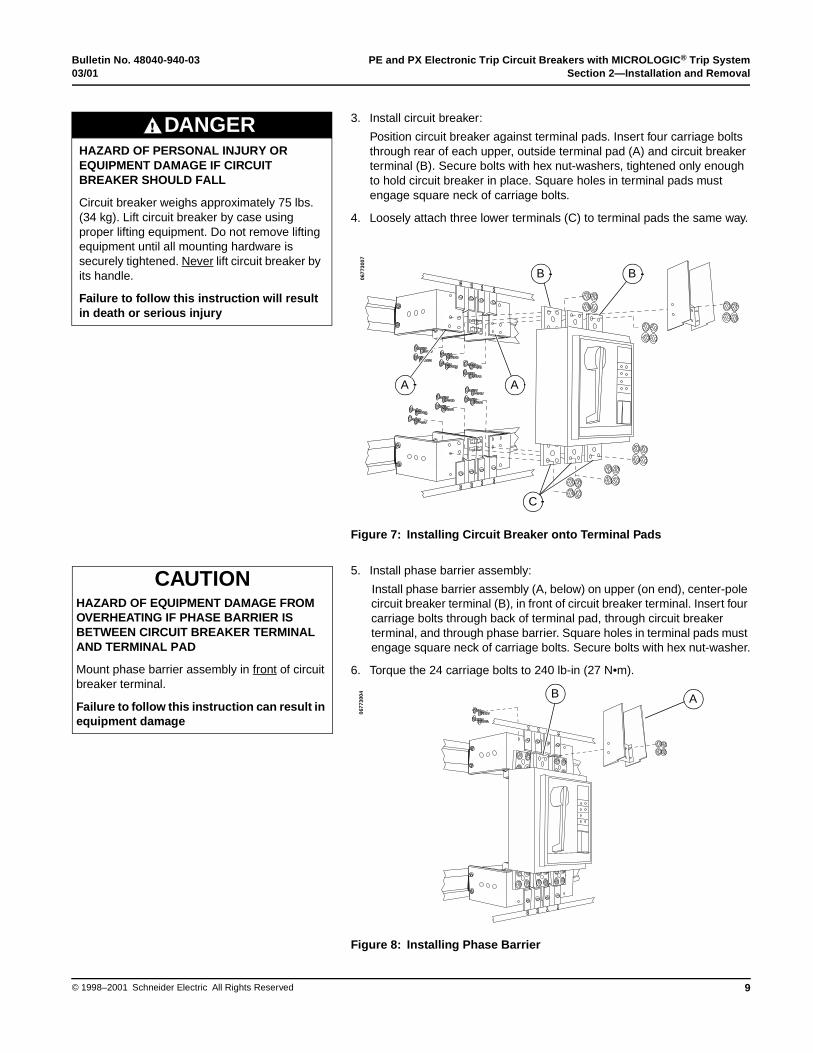
3. Install circuit breaker:
Position circuit breaker against terminal pads. Insert four carriage bolts through rear of each upper, outside terminal pad (A) and circuit breaker terminal (B). Secure bolts with hex nut-washers, tightened only enough to hold circuit breaker in place. Square holes in terminal pads must engage square neck of carriage bolts.
4. Loosely attach three lower terminals (C) to terminal pads the same way.
Figure 7: Installing Circuit Breaker onto Terminal Pads
5. Install phase barrier assembly:
Install phase barrier assembly (A, below) on upper (on end), center-pole circuit breaker terminal (B), in front of circuit breaker terminal. Insert four carriage bolts through back of terminal pad, through circuit breaker terminal, and through phase barrier. Square holes in terminal pads must engage square neck of carriage bolts. Secure bolts with hex nut-washer.
6. Torque the 24 carriage bolts to 240 lb-in (27 N•m).
Figure 8: Installing Phase Barrier
HAZARD OF PERSONAL INJURY OR EQUIPMENT DAMAGE IF CIRCUIT BREAKER SHOULD FALL
Circuit breaker weighs approximately 75 lbs. (34 kg). Lift circuit breaker by case using proper lifting equipment. Do not remove lifting equipment until all mounting hardware is securely tightened. Never lift circuit breaker by its handle.
Failure to follow this instruction will result in death or serious injury
DANGER
B B
A A
C
0677
3007
HAZARD OF EQUIPMENT DAMAGE FROM OVERHEATING IF PHASE BARRIER IS BETWEEN CIRCUIT BREAKER TERMINAL AND TERMINAL PAD
Mount phase barrier assembly in front of circuit breaker terminal.
Failure to follow this instruction can result in equipment damage
CAUTION
AB
0677
3004
PE and PX Electronic Trip Circuit Breakers with MICROLOGIC® Trip System Bulletin No. 48040-940-03Section 2—Installation and Removal 03/01
© 1998–2001 Schneider Electric All Rights Reserved10
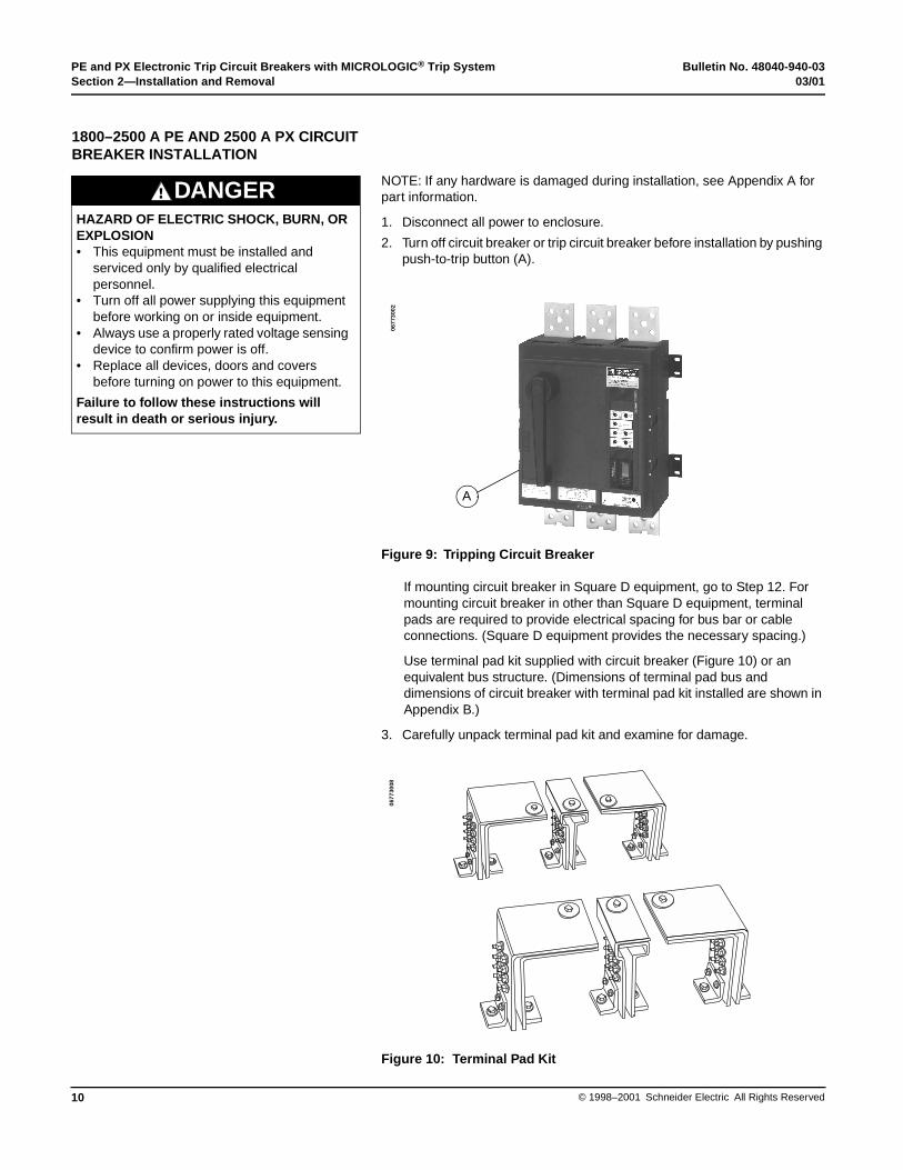
NOTE: If any hardware is damaged during installation, see Appendix A for part information.
1. Disconnect all power to enclosure.
2. Turn off circuit breaker or trip circuit breaker before installation by pushing push-to-trip button (A).
Figure 9: Tripping Circuit Breaker
If mounting circuit breaker in Square D equipment, go to Step 12. For mounting circuit breaker in other than Square D equipment, terminal pads are required to provide electrical spacing for bus bar or cable connections. (Square D equipment provides the necessary spacing.)
Use terminal pad kit supplied with circuit breaker (Figure 10) or an equivalent bus structure. (Dimensions of terminal pad bus and dimensions of circuit breaker with terminal pad kit installed are shown in Appendix B.)
3. Carefully unpack terminal pad kit and examine for damage.
Figure 10: Terminal Pad Kit
HAZARD OF ELECTRIC SHOCK, BURN, OR EXPLOSION• This equipment must be installed and
serviced only by qualified electrical personnel.
• Turn off all power supplying this equipment before working on or inside equipment.
• Always use a properly rated voltage sensing device to confirm power is off.
• Replace all devices, doors and covers before turning on power to this equipment.
Failure to follow these instructions will result in death or serious injury.
DANGER
1800–2500 A PE AND 2500 A PX CIRCUIT BREAKER INSTALLATION
A
0677
3002
0677
3008
Bulletin No. 48040-940-03 PE and PX Electronic Trip Circuit Breakers with MICROLOGIC® Trip System03/01 Section 2—Installation and Removal
11© 1998–2001 Schneider Electric All Rights Reserved
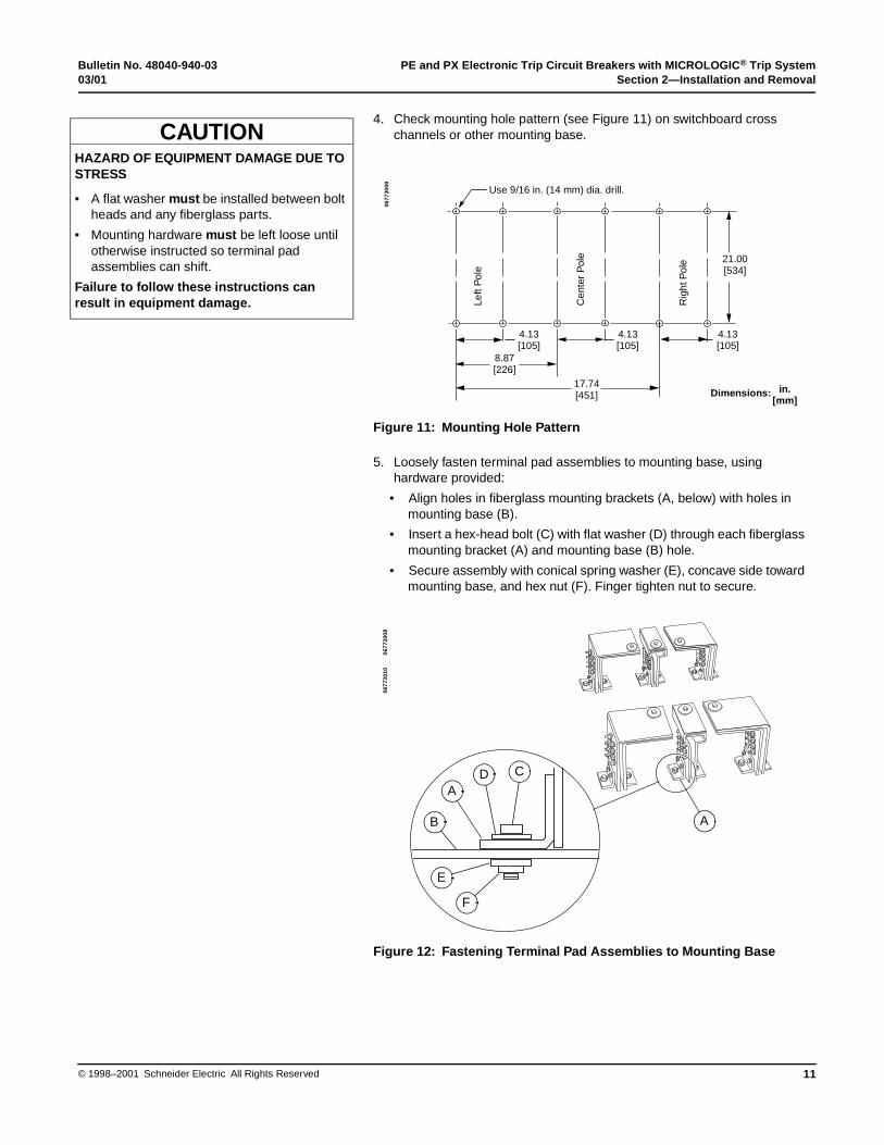
4. Check mounting hole pattern (see Figure 11) on switchboard cross channels or other mounting base.
Figure 11: Mounting Hole Pattern
5. Loosely fasten terminal pad assemblies to mounting base, using hardware provided:
• Align holes in fiberglass mounting brackets (A, below) with holes in mounting base (B).
• Insert a hex-head bolt (C) with flat washer (D) through each fiberglass mounting bracket (A) and mounting base (B) hole.
• Secure assembly with conical spring washer (E), concave side toward mounting base, and hex nut (F). Finger tighten nut to secure.
Figure 12: Fastening Terminal Pad Assemblies to Mounting Base
HAZARD OF EQUIPMENT DAMAGE DUE TO STRESS
• A flat washer must be installed between bolt heads and any fiberglass parts.
• Mounting hardware must be left loose until otherwise instructed so terminal pad assemblies can shift.
Failure to follow these instructions can result in equipment damage.
CAUTION
4.13[105]
4.13[105]
4.13[105]
8.87[226]
21.00[534]
17.74[451]
Use 9/16 in. (14 mm) dia. drill.
Left
Pol
e
Cen
ter
Pol
e
Rig
ht P
ole
0677
3009
Dimensions: in.[mm]
D C
A
B
E
F
A
0677
3008
0677
3010
PE and PX Electronic Trip Circuit Breakers with MICROLOGIC® Trip System Bulletin No. 48040-940-03Section 2—Installation and Removal 03/01
© 1998–2001 Schneider Electric All Rights Reserved12
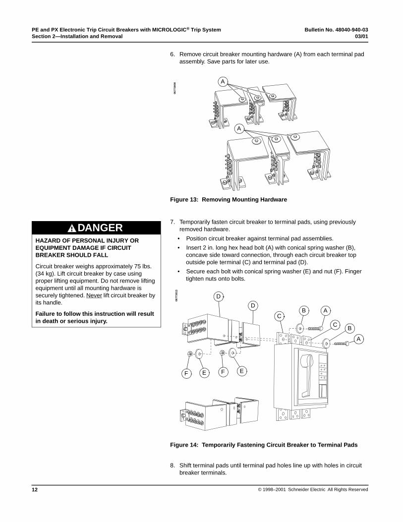
6. Remove circuit breaker mounting hardware (A) from each terminal pad assembly. Save parts for later use.
Figure 13: Removing Mounting Hardware
7. Temporarily fasten circuit breaker to terminal pads, using previously removed hardware.
• Position circuit breaker against terminal pad assemblies.
• Insert 2 in. long hex head bolt (A) with conical spring washer (B), concave side toward connection, through each circuit breaker top outside pole terminal (C) and terminal pad (D).
• Secure each bolt with conical spring washer (E) and nut (F). Finger tighten nuts onto bolts.
Figure 14: Temporarily Fastening Circuit Breaker to Terminal Pads
8. Shift terminal pads until terminal pad holes line up with holes in circuit breaker terminals.
A
A
0677
3008
HAZARD OF PERSONAL INJURY OR EQUIPMENT DAMAGE IF CIRCUIT BREAKER SHOULD FALL
Circuit breaker weighs approximately 75 lbs. (34 kg). Lift circuit breaker by case using proper lifting equipment. Do not remove lifting equipment until all mounting hardware is securely tightened. Never lift circuit breaker by its handle.
Failure to follow this instruction will result in death or serious injury.
DANGER
F E F E
D
D
CB A
CB
A
0677
3013
Bulletin No. 48040-940-03 PE and PX Electronic Trip Circuit Breakers with MICROLOGIC® Trip System03/01 Section 2—Installation and Removal
13© 1998–2001 Schneider Electric All Rights Reserved
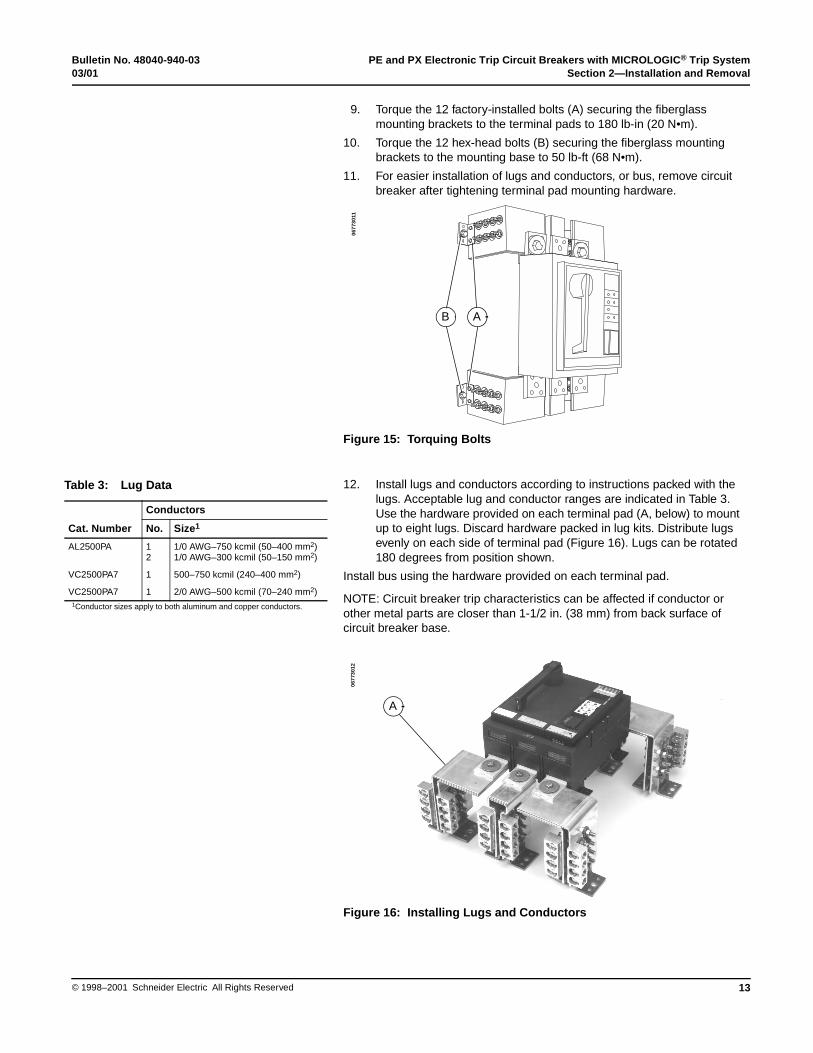
9. Torque the 12 factory-installed bolts (A) securing the fiberglass mounting brackets to the terminal pads to 180 lb-in (20 N•m).
10. Torque the 12 hex-head bolts (B) securing the fiberglass mounting brackets to the mounting base to 50 lb-ft (68 N•m).
11. For easier installation of lugs and conductors, or bus, remove circuit breaker after tightening terminal pad mounting hardware.
Figure 15: Torquing Bolts
12. Install lugs and conductors according to instructions packed with the lugs. Acceptable lug and conductor ranges are indicated in Table 3. Use the hardware provided on each terminal pad (A, below) to mount up to eight lugs. Discard hardware packed in lug kits. Distribute lugs evenly on each side of terminal pad (Figure 16). Lugs can be rotated 180 degrees from position shown.
Install bus using the hardware provided on each terminal pad.
NOTE: Circuit breaker trip characteristics can be affected if conductor or other metal parts are closer than 1-1/2 in. (38 mm) from back surface of circuit breaker base.
Figure 16: Installing Lugs and Conductors
B A
0677
3011
Table 3: Lug Data
Cat. Number
Conductors
No. Size1
AL2500PA 12
1/0 AWG–750 kcmil (50–400 mm2)1/0 AWG–300 kcmil (50–150 mm2)
VC2500PA7 1 500–750 kcmil (240–400 mm2)
VC2500PA7 1 2/0 AWG–500 kcmil (70–240 mm2)1Conductor sizes apply to both aluminum and copper conductors.
A
0677
3012
PE and PX Electronic Trip Circuit Breakers with MICROLOGIC® Trip System Bulletin No. 48040-940-03Section 2—Installation and Removal 03/01
© 1998–2001 Schneider Electric All Rights Reserved14
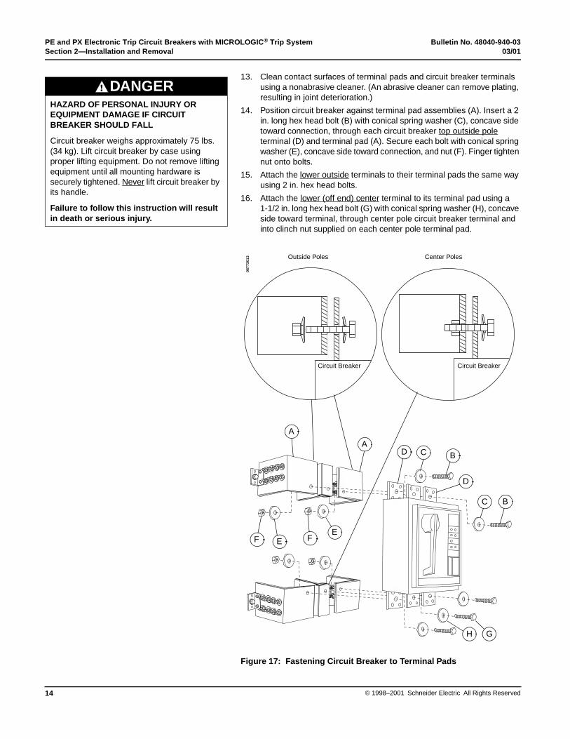
13. Clean contact surfaces of terminal pads and circuit breaker terminals using a nonabrasive cleaner. (An abrasive cleaner can remove plating, resulting in joint deterioration.)
14. Position circuit breaker against terminal pad assemblies (A). Insert a 2 in. long hex head bolt (B) with conical spring washer (C), concave side toward connection, through each circuit breaker top outside pole terminal (D) and terminal pad (A). Secure each bolt with conical spring washer (E), concave side toward connection, and nut (F). Finger tighten nut onto bolts.
15. Attach the lower outside terminals to their terminal pads the same way using 2 in. hex head bolts.
16. Attach the lower (off end) center terminal to its terminal pad using a 1-1/2 in. long hex head bolt (G) with conical spring washer (H), concave side toward terminal, through center pole circuit breaker terminal and into clinch nut supplied on each center pole terminal pad.
Figure 17: Fastening Circuit Breaker to Terminal Pads
HAZARD OF PERSONAL INJURY OR EQUIPMENT DAMAGE IF CIRCUIT BREAKER SHOULD FALL
Circuit breaker weighs approximately 75 lbs. (34 kg). Lift circuit breaker by case using proper lifting equipment. Do not remove lifting equipment until all mounting hardware is securely tightened. Never lift circuit breaker by its handle.
Failure to follow this instruction will result in death or serious injury.
DANGER
A
A
F E FE
D C B
D
C B
H G
Outside Poles Center Poles
0677
3013
Circuit Breaker Circuit Breaker
Bulletin No. 48040-940-03 PE and PX Electronic Trip Circuit Breakers with MICROLOGIC® Trip System03/01 Section 2—Installation and Removal
15© 1998–2001 Schneider Electric All Rights Reserved
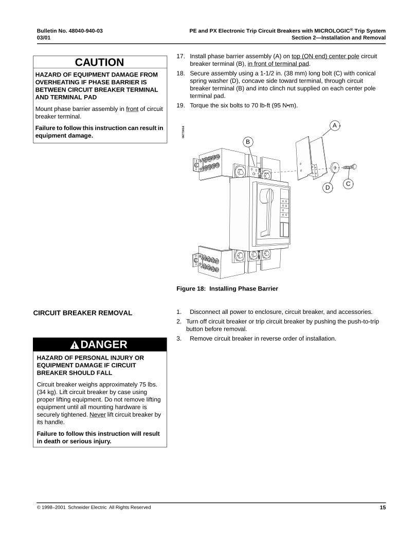
17. Install phase barrier assembly (A) on top (ON end) center pole circuit breaker terminal (B), in front of terminal pad.
18. Secure assembly using a 1-1/2 in. (38 mm) long bolt (C) with conical spring washer (D), concave side toward terminal, through circuit breaker terminal (B) and into clinch nut supplied on each center pole terminal pad.
19. Torque the six bolts to 70 lb-ft (95 N•m).
Figure 18: Installing Phase Barrier
1. Disconnect all power to enclosure, circuit breaker, and accessories.
2. Turn off circuit breaker or trip circuit breaker by pushing the push-to-trip button before removal.
3. Remove circuit breaker in reverse order of installation.
HAZARD OF EQUIPMENT DAMAGE FROM OVERHEATING IF PHASE BARRIER IS BETWEEN CIRCUIT BREAKER TERMINAL AND TERMINAL PAD
Mount phase barrier assembly in front of circuit breaker terminal.
Failure to follow this instruction can result in equipment damage.
CAUTION
A
B
DC
0677
3014
CIRCUIT BREAKER REMOVAL
HAZARD OF PERSONAL INJURY OR EQUIPMENT DAMAGE IF CIRCUIT BREAKER SHOULD FALL
Circuit breaker weighs approximately 75 lbs. (34 kg). Lift circuit breaker by case using proper lifting equipment. Do not remove lifting equipment until all mounting hardware is securely tightened. Never lift circuit breaker by its handle.
Failure to follow this instruction will result in death or serious injury.
DANGER

PE and PX Electronic Trip Circuit Breakers with MICROLOGIC® Trip System Bulletin No. 48040-940-03Section 3—Trip Unit Operation 03/01
© 1998–2001 Schneider Electric All Rights Reserved16
PX circuit breakers are equipped with the MICROLOGIC® Standard Trip System (A, below). PE circuit breakers are equipped with the MICROLOGIC Full-function Trip System (B). Both trip systems provide adjustable tripping functions and characteristics using true root-mean-square (rms) current sensing.
Adjustable rotary switches (C) on the trip unit allow the user to set the proper overcurrent or ground current protection required in the electrical system. If trip currents and time delays exceed set values, the trip system trips the circuit breaker.
NOTE: The fiber optic communications port (D) will occasionally flicker. This is not an indication of circuit breaker performance.
Figure 19: MICROLOGIC Trip System
Determine current rating by multiplying the circuit breaker sensor size by the rating plug multiplier and the trip unit LONG-TIME pickup switch setting. For example:
Rating plugs (E) are available with multipliers ranging from 0.40 to 1.00. If the rating plug is not installed, the circuit breaker will operate safely, but the rating plug multiplier will default to 0.40
The label on the circuit breaker marked “Configuration as Shipped” gives the circuit breaker configuration as it left the factory. See Appendix A for available field-installable rating plug kits.
NOTE: Ground-fault values are based on the sensor size of the circuit breaker and are not affected by changing the rating plug.
SensorSize
xRating Plug
Multiplierx
Long-time PickupSwitch Setting
=Current Rating
2000 x 0.75 x 0.8 = 1200
Section 3—Trip Unit Operation
A
11
16 20 24
34.5
7
2
LONG TIME
.8.9
.95 1.0
.6.7
.75
.5
PICKUPx P
DELAYSEC. AT 6 x P
INSTANTANEOUS6
7 8 OFF
34
5
2.5PICKUP
x P
.5.32
.2
.1.2
.32
.5
.1
SHORT TIME
5
6 78
2.53
4
2
DELAYSEC. AT12 x P
PICKUPx P
2
2I t OUT
I t IN
.5
.32 .2 .1
.2.32
.5
.1
GROUND FAULT
PICKUPX S
.45
.55 .65 .75
.25.3
.35
.2
DELAYSEC. AT
1 x S
2
2I t OUT
I t IN
FU
LL
-FU
NC
TIO
NS
ER
IES
B
RA
TIN
G P
LU
G
Max
. Am
per
e R
atin
g (
P)
= S
enso
r (S
) x
100%
CA
T N
O. :
AR
P10
0
- -
- -
-
AMMETER / TRIP INDICATOR
PHASE
0 20 40 60 80 100
% of Rating
INDICATORRESET
PHASESELECT
Press andHoldforAmmeterReset
FLASH = 90 % ON = OVERLOAD
1116 20 24
34.57
2
LONG TIME
FLASH = 90 % ON = OVERLOAD
.8.9 .95 1.0
.6.7
.75
.5
PICKUPx P
DELAYSEC. AT
INSTANTANEOUS6
7 8 8
34
5
2.5
PICKUP x P
.5.32 .1.2
.5
SHORT TIME
56 7
8
2.53
4
2
DELAY SEC. AT
PICKUPx P 2I t IN
.5
.2.32
.5
.1
GROUND FAULT
PICKUPX S.45
.55 .65 .75
.25.3
.35
.2
DELAYSEC. AT
1 x S2I t OUT
STA
ND
AR
DS
ER
IES
B
RA
TIN
G P
LU
G
Max
. Am
per
e R
atin
g (
P)
= S
enso
r (S
) x
100%
CA
T N
O. :
AR
P10
0
C
D
E
B
0677
3015
StandardTrip Unit
Full-functionTrip Unit
CURRENT RATING
HAZARD OF EQUIPMENT DAMAGE
Rating plug and ammeter/trip indicator are subject to damage from static charge. Do not handle these devices by their contacts. If either device is removed, hold it against the metal circuit breaker enclosure at least two seconds before reinstalling.
Failure to follow this instruction can result in equipment damage.
CAUTION
Bulletin No. 48040-940-03 PE and PX Electronic Trip Circuit Breakers with MICROLOGIC® Trip System03/01 Section 3—Trip Unit Operation
17© 1998–2001 Schneider Electric All Rights Reserved
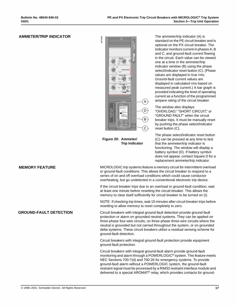
The ammeter/trip indicator (A) is standard on the PE circuit breaker and is optional on the PX circuit breaker. The indicator monitors current in phases A, B and C, and ground-fault current flowing in the circuit. Each value can be viewed one at a time in the ammeter/trip indicator window (B) using the phase select/indicator reset button (C). (Phase values are displayed in true rms. Ground-fault current values are displayed in calculated rms based on measured peak current.) A bar graph is provided indicating the level of operating current as a function of the programmed ampere rating of the circuit breaker.
The window also displays “OVERLOAD,” “SHORT CIRCUIT,” or “GROUND FAULT” when the circuit breaker trips. It must be manually reset by pushing the phase select/indicator reset button (C).
The phase select/indicator reset button (C) can be pressed at any time to test that the ammeter/trip indicator is functioning. The window will display a battery symbol (D). If battery symbol does not appear, contact Square D for a replacement ammeter/trip indicator.
MICROLOGIC trip systems feature a memory circuit for intermittent overload or ground-fault conditions. This allows the circuit breaker to respond to a series of on and off overload conditions which could cause conductor overheating, but go undetected in a conventional electronic trip device.
If the circuit breaker trips due to an overload or ground-fault condition, wait at least one minute before resetting the circuit breaker. This allows the memory to clear itself sufficiently for circuit breaker to be turned on (I).
NOTE: If checking trip times, wait 15 minutes after circuit breaker trips before resetting to allow memory to reset completely to zero.
Circuit breakers with integral ground-fault detection provide ground-fault protection or alarm on grounded neutral systems. They can be applied on three-phase four-wire circuits, on three-phase three-wire circuits where the neutral is grounded but not carried throughout the system, or on grounded delta systems. These circuit breakers utilize a residual sensing scheme for ground-fault detection.
Circuit breakers with integral ground-fault protection provide equipment ground-fault protection.
Circuit breakers with integral ground-fault alarm provide ground-fault monitoring and alarm through a POWERLOGIC® system. This feature meets NEC Sections 700-7(d) and 700-26 for emergency systems. To provide ground-fault alarm without a POWERLOGIC system, the ground-fault restraint signal must be processed by a RIM32 restraint interface module and delivered to a special AROMAT® relay, which provides contacts for ground-
11
16 20 24
34.5
7
2
LONG TIME
FLASH = 90 % ON = OVERLOAD
.8.9 .95 1.0
.6.7
.75
.5
PICKUPx P
DELAYSEC. AT 6 x P
INSTANTANEOUS6
7 8 OFF
34
5
2.5PICKUP
x P
.5.32
.2
.1.2
.32
.5
.1
SHORT TIME
5
6 78
2.53
4
2
DELAYSEC. AT12 x P
PICKUPx P
2
2I t OUT
I t IN
.5
.32.2 .1
.2.32
.5
.1
GROUNDFAULT
PICKUPX S
.45
.55 .65 .75
.25.3
.35
.2
DELAYSEC. AT
1 x S
2
2I t OUT
I t IN
FU
LL
-FU
NC
TIO
NS
ER
IES
B
RA
TIN
G P
LU
G
Max
. Am
per
e R
atin
g (
P)
= S
enso
r (S
) x
100%
CA
T N
O. :
AR
P10
0
- -
- -
-
AMMETER / TRIP INDICATOR
PHASE
0 20 40 60 80 100
% of Rating
INDICATORRESET
PHASESELECT
Press andHoldforAmmeterReset
- -
- -
-
AMMETER / TRIP INDICATOR
PHASE
0 20 40 60 80 100
% of Rating
INDICATORRESET
PHASESELECT
Press andHoldforAmmeterReset
OVERLOADSHORT CIRCUITGROUND FAULT
8888A B C GF
- - - - -
+ -OK
PHASE
Figure 20: Ammeter/Trip Indicator
A
C
B
D
0677
3016AMMETER/TRIP INDICATOR
MEMORY FEATURE
GROUND-FAULT DETECTION
PE and PX Electronic Trip Circuit Breakers with MICROLOGIC® Trip System Bulletin No. 48040-940-03Section 3—Trip Unit Operation 03/01
© 1998–2001 Schneider Electric All Rights Reserved18
fault annunciation. In either case the restraint signal exists until the ground fault is removed. Ground-fault alarm is available on PE circuit breakers only.
NOTE: Circuit breakers with ground-fault alarm DO NOT provide ground-fault protection.
Circuit breakers with either ground-fault feature are equipped with an internal ground-fault test feature. The ground-fault test system is built into the circuit breaker and eliminates the need for any additional test equipment, such as monitor panels. See Appendix C for wiring diagrams.
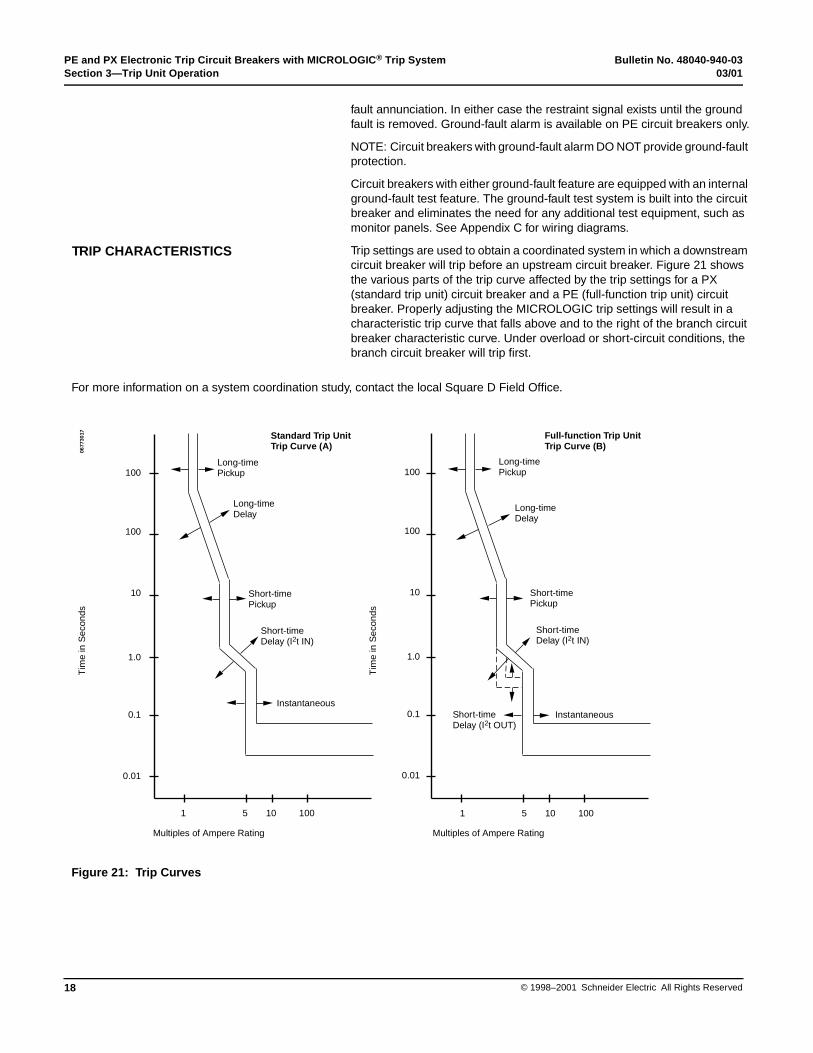
Trip settings are used to obtain a coordinated system in which a downstream circuit breaker will trip before an upstream circuit breaker. Figure 21 shows the various parts of the trip curve affected by the trip settings for a PX (standard trip unit) circuit breaker and a PE (full-function trip unit) circuit breaker. Properly adjusting the MICROLOGIC trip settings will result in a characteristic trip curve that falls above and to the right of the branch circuit breaker characteristic curve. Under overload or short-circuit conditions, the branch circuit breaker will trip first.
TRIP CHARACTERISTICS
For more information on a system coordination study, contact the local Square D Field Office.
Figure 21: Trip Curves
Standard Trip UnitTrip Curve (A)
Full-function Trip UnitTrip Curve (B)
Long-timePickup
Long-timeDelay
Short-timePickup
Short-timeDelay (I2t IN)
Instantaneous
Multiples of Ampere Rating
100
100
10
1.0
0.1
0.01
1 5 10 100 1 5 10 100
100
100
10
1.0
0.1
0.01
Long-timePickup
Long-timeDelay
Short-timePickup
Short-timeDelay (I2t IN)
InstantaneousShort-timeDelay (I2t OUT)
Multiples of Ampere Rating
0677
3017
Tim
e in
Sec
onds
Tim
e in
Sec
onds

Bulletin No. 48040-940-03 PE and PX Electronic Trip Circuit Breakers with MICROLOGIC® Trip System03/01 Section 3—Trip Unit Operation
19© 1998–2001 Schneider Electric All Rights Reserved
NOTE: Turn circuit breaker off (O) before adjusting trip unit switches.
LONG-TIME PICKUP Switch—sets maximum current level (based on circuit breaker ampere rating) which circuit breaker will carry continuously. If current exceeds this value, circuit breaker will trip after the preset delay time.
LONG-TIME DELAY Switch—sets length of time that circuit breaker will carry a sustained overcurrent below the SHORT-TIME PICKUP current level before tripping. Delay bands are labeled in seconds of overcurrent at six times the ampere rating. For maximum coordination, there are eight delay bands.
Indicator—the trip unit includes an indicator (A) that will flash at 90% of the LONG-TIME PICKUP level and will be lit continuously above 100% of the pickup level.
Figure 22: Long-time Pickup and Delay Switch
SHORT-TIME PICKUP Switch—sets current level (based on circuit breaker ampere rating) between the LONG-TIME PICKUP level and the INSTANTANEOUS PICKUP level at which circuit breaker will trip after the preset short-time delay.
SHORT-TIME DELAY Switch—sets length of time circuit breaker will carry an overcurrent which exceeds the SHORT-TIME PICKUP level but is less than the INSTANTANEOUS PICKUP level. The delay can be set to four positions of I2t ramp function (I2t IN).
Figure 23: Short-time Pickup and Delay Switch
STANDARD TRIP UNIT FUNCTIONS
Long-time Trip Function
11
16 2024
34.5
7
2
LONG TIME
FLASH = 90 % ON = OVERLOAD
.8
.9.95 1.0
.6.7
.75
.5
PICKUPx P
DELAYSEC. AT
6 x PA
0677
3018
Short-time Trip Function
.5.32 .1.2
.5
SHORT TIME
5
67
8
2.53
4
2
DELAY SEC. AT
PICKUPx P 2I t IN
12 X P
0677
3019
PE and PX Electronic Trip Circuit Breakers with MICROLOGIC® Trip System Bulletin No. 48040-940-03Section 3—Trip Unit Operation 03/01
© 1998–2001 Schneider Electric All Rights Reserved20
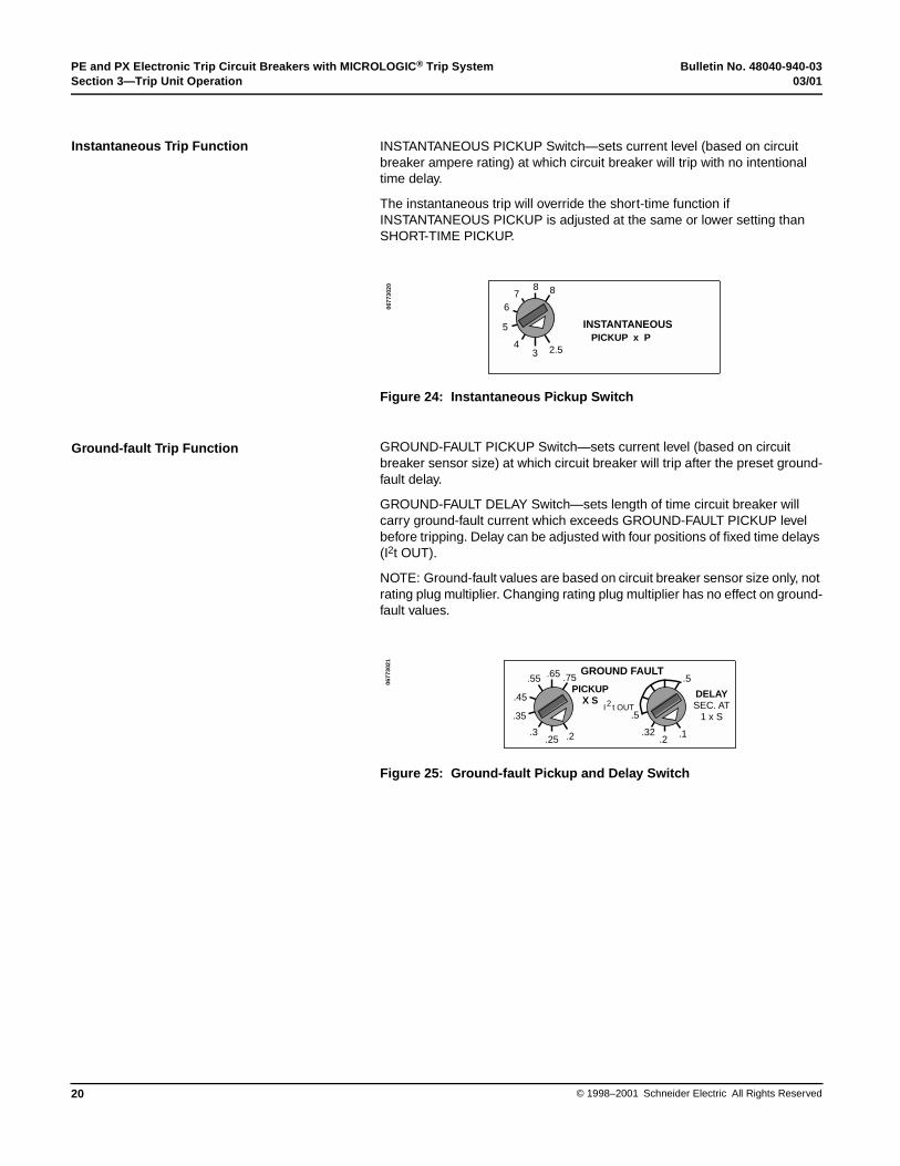
INSTANTANEOUS PICKUP Switch—sets current level (based on circuit breaker ampere rating) at which circuit breaker will trip with no intentional time delay.
The instantaneous trip will override the short-time function if INSTANTANEOUS PICKUP is adjusted at the same or lower setting than SHORT-TIME PICKUP.
Figure 24: Instantaneous Pickup Switch
GROUND-FAULT PICKUP Switch—sets current level (based on circuit breaker sensor size) at which circuit breaker will trip after the preset ground-fault delay.
GROUND-FAULT DELAY Switch—sets length of time circuit breaker will carry ground-fault current which exceeds GROUND-FAULT PICKUP level before tripping. Delay can be adjusted with four positions of fixed time delays (I2t OUT).
NOTE: Ground-fault values are based on circuit breaker sensor size only, not rating plug multiplier. Changing rating plug multiplier has no effect on ground-fault values.
Figure 25: Ground-fault Pickup and Delay Switch
Instantaneous Trip Function
INSTANTANEOUS
67
8 8
34
5
2.5PICKUP x P
0677
3020
Ground-fault Trip Function
.5
.2.32
.5
.1
GROUND FAULT
.45
.55 .65 .75
.25.3
.35
.2
DELAYSEC. AT
1 x S2I t OUT
PICKUPX S
0677
3021

Bulletin No. 48040-940-03 PE and PX Electronic Trip Circuit Breakers with MICROLOGIC® Trip System03/01 Section 3—Trip Unit Operation
21© 1998–2001 Schneider Electric All Rights Reserved
NOTE: Turn circuit breaker off (O) before adjusting trip unit switches.
LONG-TIME PICKUP Switch—sets maximum current level (based on circuit breaker ampere rating) which circuit breaker will carry continuously. If current exceeds this value, circuit breaker will trip after the preset delay time.
LONG-TIME DELAY Switch—sets length of time that circuit breaker will carry a sustained overcurrent below the SHORT-TIME PICKUP current level before tripping. Delay bands are labeled in seconds of overcurrent at six times the ampere rating. For maximum coordination, there are eight delay bands.
Indicator—the trip unit includes an indicator (A) that will flash at 90% of the LONG-TIME PICKUP level and will be lit continuously above 100% of the pickup level.
Figure 26: Long-time Pickup and Delay Switch
SHORT-TIME PICKUP Switch—sets current level (based on circuit breaker ampere rating) between the LONG-TIME PICKUP level and the INSTANTANEOUS PICKUP level at which circuit breaker will trip after the preset short-time delay.
SHORT-TIME DELAY Switch—sets length of time circuit breaker will carry an overcurrent which exceeds the SHORT-TIME PICKUP level but is less than the INSTANTANEOUS PICKUP level. The delay can be set to four positions of I2t ramp function (I2t IN) or four positions of fixed time delays (I2t OUT).
Figure 27: Short-time Pickup and Delay Switch
FULL-FUNCTION TRIP UNIT FUNCTION
Long-time Trip Function
A
11
1620
24
34.5
7
2
LONG TIME
FLASH = 90 % ON = OVERLOAD
.8
.9.95 1.0
.6.7
.75
.5
PICKUPx P
DELAYSEC. AT
6 x P
0677
3022
Short-time Trip Function
.5.32
.2
.1.2
.32
.5
.1
SHORT TIME
5
6 78
2.53
4
2
DELAYSEC. AT12 x P
PICKUPx P 2
2I t OUT
I t IN
0677
3023

PE and PX Electronic Trip Circuit Breakers with MICROLOGIC® Trip System Bulletin No. 48040-940-03Section 3—Trip Unit Operation 03/01
© 1998–2001 Schneider Electric All Rights Reserved22
INSTANTANEOUS PICKUP Switch—sets current level (based on circuit breaker ampere rating) at which circuit breaker will trip with no intentional time delay.
In circuit breakers with both short-time and instantaneous trip, the instantaneous trip will override the short-time function if the INSTANTANEOUS PICKUP is adjusted at the same or lower setting than the SHORT-TIME PICKUP.
Figure 28: Instantaneous Pickup Switch
In circuit breakers with both short-time and instantaneous trip, the adjustable instantaneous trip can be disabled by setting INSTANTANEOUS PICKUP to OFF. A high-level instantaneous override remains in effect.
GROUND-FAULT PICKUP Switch—sets current level (based on circuit breaker sensor size) at which circuit breaker will trip after the preset ground-fault delay.
GROUND-FAULT DELAY Switch—sets length of time circuit breaker will carry ground-fault current which exceeds GROUND-FAULT PICKUP level before tripping. Delay can be adjusted with four positions of I2t ramp function (I2t IN) or four positions of fixed time delays (I2t OUT).
NOTE: Ground-fault pick-up values are based on circuit breaker sensor size only, not rating plug multiplier. Changing rating plug multiplier has no effect on ground-fault values.
Figure 29: Ground-fault Pickup and Delay Switch
GROUND-FAULT ALARM Switch—sets current level (based on circuit breaker sensor size) at which circuit breaker will signal that a ground fault is present. The signal exists until the ground fault is removed and the reset button is pressed.
NOTE: Ground-fault pick-up values are based on circuit breaker sensor size only, not rating plug multiplier. Changing rating plug multiplier has no effect on ground-fault values.
Instantaneous Trip Function
HAZARD OF PERSONAL INJURY, DEATH OR PROPERTY DAMAGE
Turning the instantaneous trip to OFF can cause the electrical system to carry overcurrents for longer than design capabilities allow. Turning instantaneous trip to OFF must be done only by qualified personnel.
Failure to follow this instruction will result in death or serious injury.
DANGER
INSTANTANEOUS
67
8 OFF
34
5
2.5PICKUP x P
0677
3024
Ground-fault Trip Function
.5.32
.2
.1.2
.32
.5
.1
GROUND FAULT
.45
.55.65 .75
.25.3
.35
.2
DELAYSEC. AT1 x S
PICKUPx S 2
2I t OUT
I t IN
0677
3025
Ground-fault Alarm Function
Figure 30: Ground-fault Alarm Pickup Switch
GROUND FAULTALARM
PICKUP X S
.45
.55 .65 .75
.25.3
.35
.2
0677
3026
Bulletin No. 48040-940-03 PE and PX Electronic Trip Circuit Breakers with MICROLOGIC® Trip System03/01 Section 4—Trip Unit Adjustments and Control Wiring
23© 1998–2001 Schneider Electric All Rights Reserved
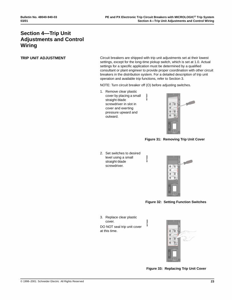
Circuit breakers are shipped with trip unit adjustments set at their lowest settings, except for the long-time pickup switch, which is set at 1.0. Actual settings for a specific application must be determined by a qualified consultant or plant engineer to provide proper coordination with other circuit breakers in the distribution system. For a detailed description of trip unit operation and available trip functions, refer to Section 3.
NOTE: Turn circuit breaker off (O) before adjusting switches.
1. Remove clear plastic cover by placing a small straight-blade screwdriver in slot in cover and exerting pressure upward and outward.
2. Set switches to desired level using a small straight-blade screwdriver.
3. Replace clear plastic cover.
DO NOT seal trip unit cover at this time.
Section 4—Trip Unit Adjustments and Control Wiring
TRIP UNIT ADJUSTMENT
11
16 20 24
34.5
7
2
LONG TIME
FLASH = 90 % ON = OVERLOAD
.8.9 .95 1.0
.6.7
.75
.5
DELAYSEC. AT 6 x P
INSTANTANEOUS6
7 8 OFF
34
5
2.5PICKUP
x P
.5.32
.2
.1.2
.32
.5
.1
SHORT TIME
5
6 78
2.53
4
2
DELAYSEC. AT12 x P
PICKUPx P
2
2I t OUT
I t IN
.5
.32.2 .1
.2.32
.5
.1
GROUNDFAULT
PICKUPX S
.45
.55 .65 .75
.25.3
.35
.2
DELAYSEC. AT
1 x S
2
2I t OUT
I t IN
FU
LL
-FU
NC
TIO
NS
ER
IES
B
RA
TIN
G P
LU
G
Max
. Am
per
e R
atin
g (
P)
= S
enso
r (S
) x
100%
CA
T N
O. :
AR
P10
0
- -
- -
-
AMMETER / TRIP INDICATOR
PHASE
0 20 40 60 80 100
% of Rating
INDICATORRESET
PHASESELECT
Press andHoldforAmmeterReset
Figure 31: Removing Trip Unit Cover
0677
3027
11
16 20 24
34.5
7
2
LONG TIME
FLASH = 90 % ON = OVERLOAD
.8.9 .95 1.0
.6.7
.75
.5
PICKUPx P
DELAYSEC. AT 6 x P
INSTANTANEOUS6
7 8 OFF
34
5
2.5PICKUP
x P
.5.32
.2
.1.2
.32
.5
.1
SHORT TIME
5
6 78
2.53
4
2
DELAYSEC. AT12 x P
PICKUPx P
2
2I t OUT
I t IN
.5
.32.2 .1
.2.32
.5
.1
GROUNDFAULT
PICKUPX S
.45
.55 .65 .75
.25.3
.35
.2
DELAYSEC. AT
1 x S
2
2I t OUT
I t IN
FU
LL
-FU
NC
TIO
NS
ER
IES
B
RA
TIN
G P
LU
G
Max
. Am
per
e R
atin
g (
P)
= S
enso
r (S
) x
100%
CA
T N
O. :
AR
P10
0
- -
- -
-
AMMETER / TRIP INDICATOR
PHASE
0 20 40 60 80 100
% of Rating
INDICATORRESET
PHASESELECT
Press andHoldforAmmeterReset
Figure 32: Setting Function Switches
0677
3028
11
16 20 24
34.5
7
2
LONG TIME
FLASH = 90 % ON = OVERLOAD
.8.9 .95 1.0
.6.7
.75
.5
PICKUPx P
DELAYSEC. AT 6 x P
INSTANTANEOUS6
7 8 OFF
34
5
2.5PICKUP
x P
.5.32
.2
.1.2
.32
.5
.1
SHORT TIME
5
6 78
2.53
4
2
DELAYSEC. AT12 x P
PICKUPx P
2
2I t OUT
I t IN
.5
.32.2 .1
.2.32
.5
.1
GROUNDFAULT
PICKUPX S
.45
.55 .65 .75
.25.3
.35
.2
DELAYSEC. AT
1 x S
2
2I t OUT
I t IN
FU
LL
-FU
NC
TIO
NS
ER
IES
B
RA
TIN
G P
LU
G
Max
. Am
per
e R
atin
g (
P)
= S
enso
r (S
) x
100%
CA
T N
O. :
AR
P10
0
- -
- -
-
AMMETER / TRIP INDICATOR
PHASE
0 20 40 60 80 100
% of Rating
INDICATORRESET
PHASESELECT
Press andHoldforAmmeterReset
Figure 33: Replacing Trip Unit Cover
0677
3029
PE and PX Electronic Trip Circuit Breakers with MICROLOGIC® Trip System Bulletin No. 48040-940-03Section 4—Trip Unit Adjustments and Control Wiring 03/01
© 1998–2001 Schneider Electric All Rights Reserved24
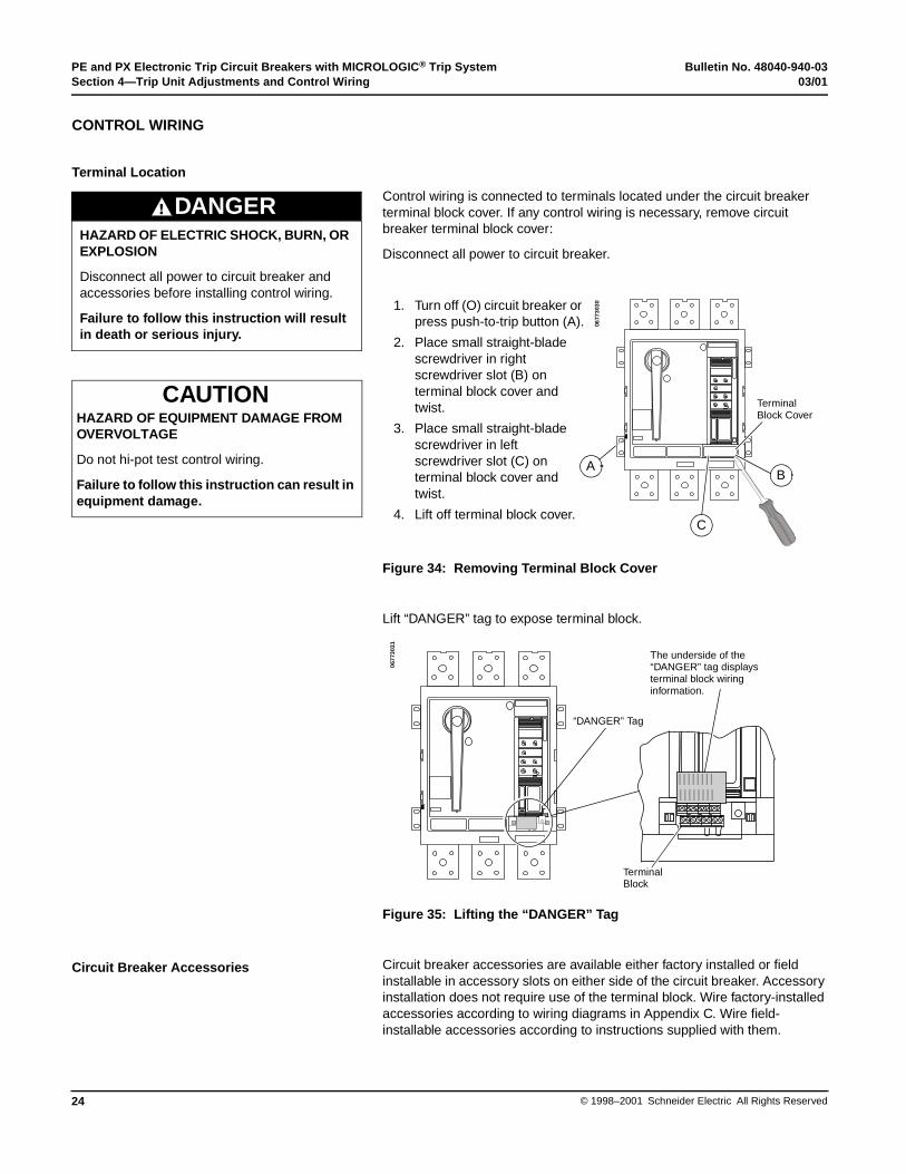
Control wiring is connected to terminals located under the circuit breaker terminal block cover. If any control wiring is necessary, remove circuit breaker terminal block cover:
Disconnect all power to circuit breaker.
Figure 34: Removing Terminal Block Cover
Lift “DANGER” tag to expose terminal block.
Figure 35: Lifting the “DANGER” Tag
Circuit breaker accessories are available either factory installed or field installable in accessory slots on either side of the circuit breaker. Accessory installation does not require use of the terminal block. Wire factory-installed accessories according to wiring diagrams in Appendix C. Wire field-installable accessories according to instructions supplied with them.
CONTROL WIRING
Terminal Location
HAZARD OF ELECTRIC SHOCK, BURN, OR EXPLOSION
Disconnect all power to circuit breaker and accessories before installing control wiring.
Failure to follow this instruction will result in death or serious injury.
DANGER
1. Turn off (O) circuit breaker or press push-to-trip button (A).
2. Place small straight-blade screwdriver in right screwdriver slot (B) on terminal block cover and twist.
3. Place small straight-blade screwdriver in left screwdriver slot (C) on terminal block cover and twist.
4. Lift off terminal block cover. C
B
TerminalBlock Cover
0677
3030
A
HAZARD OF EQUIPMENT DAMAGE FROM OVERVOLTAGE
Do not hi-pot test control wiring.
Failure to follow this instruction can result in equipment damage.
CAUTION
xxxx
xxxx
xx
xxxx
xxxx
xx
xxxx
xxxx
xx
xxxx
xxxx
xx
xxxx
xxxx
xx
xxxx
xxxx
xx
xxxx
xxxx
xx
xxxx
xxxx
xx
xxxx
xxxx
xx
xxxx
xxxx
xx
xxxx
xxxx
xx
xxxx
xxxx
xx
xxxx
xxxx
xx
xxxx
xxxx
xx
xxxx
xxxx
xx
xxxx
xxxx
xx
The underside of the “DANGER” tag displays terminal block wiring information.
“DANGER” Tag
TerminalBlock
0677
3031
Circuit Breaker Accessories
Bulletin No. 48040-940-03 PE and PX Electronic Trip Circuit Breakers with MICROLOGIC® Trip System03/01 Section 4—Trip Unit Adjustments and Control Wiring
25© 1998–2001 Schneider Electric All Rights Reserved
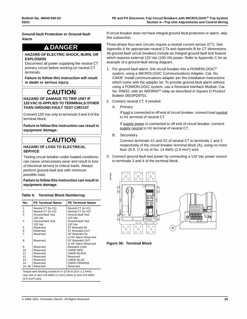
If circuit breaker does not have integral ground-fault protection or alarm, skip this subsection.
Three-phase four-wire circuits require a neutral current sensor (CT). See Appendix A for appropriate neutral CTs and Appendix B for CT dimensions. All ground-fault circuit breakers include an integral ground-fault test feature which requires external 120 Vac (100 VA) power. Refer to Appendix C for an example of a ground-fault wiring diagram.
1. For ground-fault alarm, link circuit breaker into a POWERLOGIC® system, using a MICROLOGIC Communications Adapter, Cat. No. CIM3F. Install communications adapter per the installation instructions which come with the adapter kit. To provide ground-fault alarm without using a POWERLOGIC system, use a Restraint Interface Module, Cat. No. RIM32, with an AROMAT® relay as described in Square D Product Bulletin 0602PD9701.
2. Connect neutral CT, if needed:
A. Primary
If load is connected to off end of circuit breaker, connect load neutral to H1 terminal of neutral CT.
If supply power is connected to off end of circuit breaker, connect supply neutral to H1 terminal of neutral CT.
B. Secondary
Connect terminals X1 and X2 of neutral CT to terminals 1 and 2 respectively of the circuit breaker terminal block (A), using no more than 25 ft. (7.6 m) of No. 14 AWG (2.5 mm2) wire.
3. Connect ground-fault test power by connecting a 120 Vac power source to terminals 3 and 4 of the terminal block.
Figure 36: Terminal Block
Ground-fault Protection or Ground-fault Alarm
HAZARD OF DAMAGE TO TRIP UNIT IF 120 VAC IS APPLIED TO TERMINALS OTHER THAN GROUND-FAULT TEST CIRCUIT
Connect 120 Vac only to terminals 3 and 4 of the terminal block.
Failure to follow this instruction can result in equipment damage.
CAUTION
HAZARD OF ELECTRIC SHOCK, BURN, OR EXPLOSIONDisconnect all power supplying the neutral CT primary circuit before working on neutral CT terminals.
Failure to follow this instruction will result in death or serious injury.
DANGER
HAZARD OF LOSS TO ELECTRICAL SERVICE
Testing circuit breaker under loaded conditions can cause unnecessary wear and result in loss of electrical service to critical loads. Always perform ground-fault test with minimum possible load.
Failure to follow this instruction can result in equipment damage.
CAUTION
Table 4: Terminal Block Numbering
No. PX Terminal Name PE Terminal Name
123
4
567
8
9101112131415–16
Neutral CT (to X1)Neutral CT (to X2)Ground-fault Test120 VacGround-fault Test120 VacReservedReservedReserved
Reserved
ReservedReservedReservedReservedReservedReservedReserved
Neutral CT (to X1)Neutral CT (to X2)Ground-fault Test120 VacGround-fault Test120 VacST Restraint INST Restraint OUTGF Restraint IN or GF Alarm ReservedGF Restraint OUT or GF Alarm ReservedRestraint COMCIM3F-REDCIM3F-BLACKReservedCIM3F-BLUECIM3F-ORANGEReserved
Torque wire binding screws to 5–10 lb-in (0.6–1.1 N•m).Use one or two #18 AWG (1 mm2) wires or one #14 AWG (2.5 mm2) wire.
xxxx
xxxx
xx
xxxx
xxxx
xx
xxxx
xxxx
xx
xxxx
xxxx
xx
xxxx
xxxx
xx
xxxx
xxxx
xx
xxxx
xxxx
xx
xxxx
xxxx
xx
xxxx
xxxx
xx
xxxx
xxxx
xx
xxxx
xxxx
xx
xxxx
xxxx
xx
xxxx
xxxx
xx
xxxx
xxxx
xx
xxxx
xxxx
xx
xxxx
xxxx
xx
A
0677
3031

PE and PX Electronic Trip Circuit Breakers with MICROLOGIC® Trip System Bulletin No. 48040-940-03Section 4—Trip Unit Adjustments and Control Wiring 03/01
© 1998–2001 Schneider Electric All Rights Reserved26
To link a PE circuit breaker to a POWERLOGIC® System, use a MICROLOGIC® Communications Adapter, Cat. No. CIM3F. Install communications adapter per the installation instructions which come with the adapter kit. PX circuit breakers cannot be linked to POWERLOGIC systems.
Zone-selective interlocking (ZSI) allows electronic trip circuit breakers to communicate fault information with each other. This permits faster tripping and reduces switchboard or panelboard stresses without a loss of circuit breaker coordination.
POWERLOGIC® System (PE Circuit Breaker Only)
Zone-selective Interlocking (PE Circuit Breaker Only)
Circuit breakers must be coordinated for ZSI to work effectively. This requires a system coordination study. For more information on a system coordination study, contact the local Square D Field Office.
Coordination is done by adjusting the MICROLOGIC® trip settings to obtain a coordinated system in which a downstream circuit breaker will trip before an upstream circuit breaker under overload, short-circuit, or ground-fault conditions.
During a short-circuit or ground-fault condition on a ZSI system, the circuit breaker directly ahead of the fault sends a signal upstream via control wiring to restrain upstream devices from tripping and then trips with no intentional time delay to clear the fault. Upstream devices which receive a restraint signal obey their short-time and/or ground-fault delay settings to maintain coordination in other areas of the system. Upstream devices which do not receive a restraint signal trip with no intentional time delay.
Allowable ZSI combinations are shown in Table 5. (Series numbers for current design circuit breakers end in B, for example PE Series 6B.) For double-ended or larger systems, or systems which contain circuit breakers from different columns in Table 5, contact the local Square D Field Office for combination information.
Short-time delay and ground-fault delay can be interlocked either simultaneously or independently. Refer to Appendix C for an example of a zone-selective interlocking wiring diagram.
The circuit breaker may be self-restrained by connecting its input terminal to its own output terminal. This allows devices downstream to trip and clear the fault. Self-restrain the circuit breaker if:
• the circuit breaker is feeding another panel
and
• there are no electronic trip circuit breakers or type GC Ground Fault Sensing Systems downstream from the circuit breaker being installed.
The circuit breaker may be unrestrained by not connecting its input terminal to any output terminal. This results in the circuit breaker ignoring its programmed delay values and tripping with no intentional delay to clear the fault. An electronic trip circuit breaker is left unrestrained only if:
• there are no other overcurrent protection devices between it and the load that it is feeding
and
• the load requires no intentional delay time before the circuit breaker trips.
Table 5: ZSI Combinations
MIC
RO
LO
GIC
#.0
x Tr
ip U
nit
s
Sq
uar
e D
MIC
RO
LO
GIC
Ser
ies
B T
rip
Un
its
Sq
uar
e D
GC
-100
Gro
un
d-f
ault
Rel
ay
for
Eq
uip
men
t P
rote
ctio
n
Sq
uar
e D
GC
-200
Gro
un
d-f
ault
Rel
ay f
or
Eq
uip
men
t P
rote
ctio
n
Mer
lin G
erin
ST
R58
Tri
p U
nit
s
Fed
eral
Pio
nee
r U
SR
C a
nd
US
RC
M T
rip
Un
its
MICROLOGIC #.0x Trip Units 15 R R 15 15 R
Square D MICROLOGIC Series B Trip Units R 26 R R R 15
Square D GC-100 Ground-fault Relay for Equipment Protection
R R 7 R R R
Square D GC-200 Ground-fault Relay for Equipment Protection
15 R R 15 15 R
Merlin Gerin STR58 Trip Units 15 R R 15 15 R
Merlin Gerin STR53 Trip Units 15 R R 15 15 R
Federal Pioneer USRC and USRCM Trip Units R 15 R R R 15
Square D Add-on Ground Fault Module for Equipment Protection R 5 R R R R
R—RIM module is required to restrain any devices.Numerical References—Maximum number of upstream circuit breakers which can be restrained without requiring a RIM Module.
Upstream Device
Downstream Device(sends output to RIM)
(receives input from RIM)
Bulletin No. 48040-940-03 PE and PX Electronic Trip Circuit Breakers with MICROLOGIC® Trip System03/01 Section 4—Trip Unit Adjustments and Control Wiring
27© 1998–2001 Schneider Electric All Rights Reserved
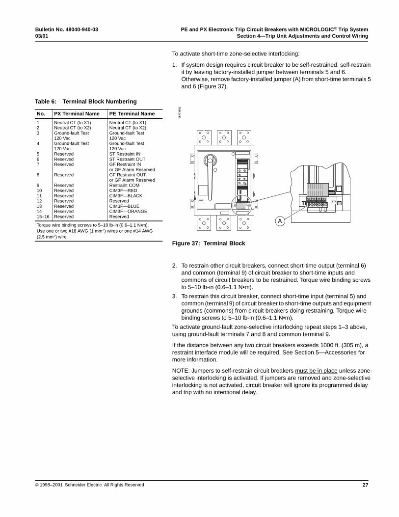
To activate short-time zone-selective interlocking:
1. If system design requires circuit breaker to be self-restrained, self-restrain it by leaving factory-installed jumper between terminals 5 and 6. Otherwise, remove factory-installed jumper (A) from short-time terminals 5 and 6 (Figure 37).
Figure 37: Terminal Block
2. To restrain other circuit breakers, connect short-time output (terminal 6) and common (terminal 9) of circuit breaker to short-time inputs and commons of circuit breakers to be restrained. Torque wire binding screws to 5–10 lb-in (0.6–1.1 N•m).
3. To restrain this circuit breaker, connect short-time input (terminal 5) and common (terminal 9) of circuit breaker to short-time outputs and equipment grounds (commons) from circuit breakers doing restraining. Torque wire binding screws to 5–10 lb-in (0.6–1.1 N•m).
To activate ground-fault zone-selective interlocking repeat steps 1–3 above, using ground-fault terminals 7 and 8 and common terminal 9.
If the distance between any two circuit breakers exceeds 1000 ft. (305 m), a restraint interface module will be required. See Section 5—Accessories for more information.
NOTE: Jumpers to self-restrain circuit breakers must be in place unless zone-selective interlocking is activated. If jumpers are removed and zone-selective interlocking is not activated, circuit breaker will ignore its programmed delay and trip with no intentional delay.
Table 6: Terminal Block Numbering
No. PX Terminal Name PE Terminal Name
123
4
567
8
9101112131415–16
Neutral CT (to X1)Neutral CT (to X2)Ground-fault Test120 VacGround-fault Test120 VacReservedReservedReserved
Reserved
ReservedReservedReservedReservedReservedReservedReserved
Neutral CT (to X1)Neutral CT (to X2)Ground-fault Test120 VacGround-fault Test120 VacST Restraint INST Restraint OUTGF Restraint IN or GF Alarm ReservedGF Restraint OUT or GF Alarm ReservedRestraint COMCIM3F—REDCIM3F—BLACKReservedCIM3F—BLUECIM3F—ORANGEReserved
Torque wire binding screws to 5–10 lb-in (0.6–1.1 N•m).Use one or two #18 AWG (1 mm2) wires or one #14 AWG (2.5 mm2) wire.
xxxx
xxxx
xx
xxxx
xxxx
xx
xxxx
xxxx
xx
xxxx
xxxx
xx
xxxx
xxxx
xx
xxxx
xxxx
xx
xxxx
xxxx
xx
xxxx
xxxx
xx
xxxx
xxxx
xx
xxxx
xxxx
xx
xxxx
xxxx
xx
xxxx
xxxx
xx
xxxx
xxxx
xx
xxxx
xxxx
xx
xxxx
xxxx
xx
xxxx
xxxx
xx
A
0677
3031

PE and PX Electronic Trip Circuit Breakers with MICROLOGIC® Trip System Bulletin No. 48040-940-03Section 4—Trip Unit Adjustments and Control Wiring 03/01
© 1998–2001 Schneider Electric All Rights Reserved28
1. Route wires out of wire exit (A).
2. Fold “DANGER” tag (B) down over terminal block.
3. Place terminal block cover (C) back in place and press down to snap into place.
Figure 38: Control Wire Routing
Test ground-fault protection or alarm, if installed:
1. Energize 120 Vac power source connected to ground-fault test circuit.
2. Depress ground-fault push-to-test button (A, below).
A. Circuit breakers with integral ground-fault protection will trip in less than a second and ammeter/trip indicator (B) will read “GROUND FAULT.”
Figure 39: Testing Ground-fault Feature
Route Control Wiring
BA
C
0677
3032
Test Ground-fault Feature
HAZARD OF LOSS TO ELECTRICAL SERVICE
Testing circuit breaker under loaded conditions can cause unnecessary wear and result in loss of electrical service to critical loads. Always perform ground-fault test with minimum possible load.
Failure to follow this instruction can result in equipment damage.
CAUTION
A
- -
- -
-
AMMETER / TRIP INDICATOR
PHASE
0 20 40 60 80 100
% of Rating
INDICATORRESET
PHASESELECT
Press andHoldforAmmeterReset
8888- - - - -
BC
0677
3042
0677
3002
Bulletin No. 48040-940-03 PE and PX Electronic Trip Circuit Breakers with MICROLOGIC® Trip System03/01 Section 4—Trip Unit Adjustments and Control Wiring
29© 1998–2001 Schneider Electric All Rights Reserved
After circuit breaker trips:
1. Reset circuit breaker by rotating handle down, through the OFF position, to the RESET position.
2. Reset ammeter/trip indicator (B) by pushing the indicator reset button (C).
If the circuit breaker does not trip, refer to Section 6—Troubleshooting.
B. Circuit breakers with integral ground-fault alarm will send an alarm signal indicating that a ground fault is present.
NOTE: Circuit breakers with ground-fault alarm will not trip or indicate a trip. While the push-to-test button is depressed, the ammeter in the circuit breaker will indicate a ground-fault current value and the circuit breaker will signal a ground fault.
If an alarm signal is not sent, refer to Section 6—Troubleshooting.
For detailed instructions on testing the integral ground-fault system, refer to Ground-fault Field Test Procedure supplied with circuit breaker.
Before placing the circuit breaker in service, verify that it has been checked and installed according to this instruction manual. As a last check, make sure all covers and barriers, such as the trip unit cover, terminal block cover and phase barrier are in place.
Circuit breaker installation is now complete.
CHECK INSTALLATION
HAZARD OF ELECTRIC SHOCK, BURN, OR EXPLOSION
• The initial energizing of the equipment is potentially hazardous.
• Overcurrent conditions can result from damage undetected during receiving inspection or from improper installation.
• Qualified electrical personnel must be present during energizing. Beware of potential hazards, wear personal protective equipment and take adequate safety precautions.
Failure to follow these instructions will result in death or serious injury.
DANGER
PE and PX Electronic Trip Circuit Breakers with MICROLOGIC® Trip System Bulletin No. 48040-940-03Section 4—Trip Unit Adjustments and Control Wiring 03/01
© 1998–2001 Schneider Electric All Rights Reserved30
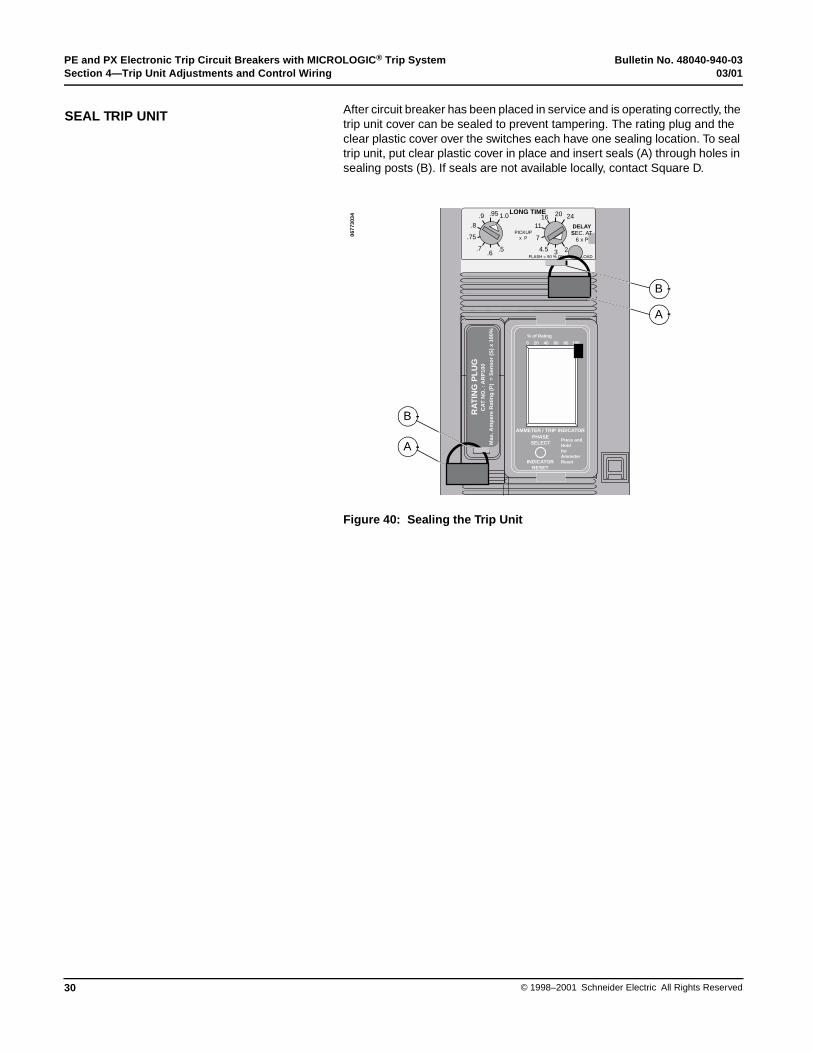
After circuit breaker has been placed in service and is operating correctly, the trip unit cover can be sealed to prevent tampering. The rating plug and the clear plastic cover over the switches each have one sealing location. To seal trip unit, put clear plastic cover in place and insert seals (A) through holes in sealing posts (B). If seals are not available locally, contact Square D.
Figure 40: Sealing the Trip Unit
SEAL TRIP UNIT
1116 20 24
34.5
7
2
LONG TIME
FLASH = 90 % ON = OVERLOAD
.8.9 .95 1.0
.6.7
.75
.5
PICKUPx P
DELAYSEC. AT 6 x P
RA
TIN
G P
LU
G
Max
. Am
per
e R
atin
g (
P)
= S
enso
r (S
) x
100%
CA
T N
O. :
AR
P10
0
- -
- -
-
AMMETER / TRIP INDICATOR
PHASE
0 20 40 60 80 100
% of Rating
INDICATORRESET
PHASESELECT
Press andHoldforAmmeterReset
B
A
B
A
0677
3034
Bulletin No. 48040-940-03 PE and PX Electronic Trip Circuit Breakers with MICROLOGIC® Trip System03/01 Section 5—Accessories
31© 1998–2001 Schneider Electric All Rights Reserved
UL Listed accessories are available for either factory or field installation. This section provides a brief description of each accessory. Wiring diagrams can be found in Appendix C.
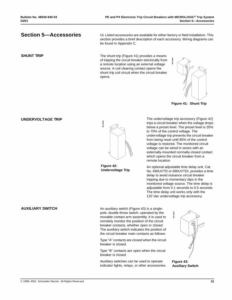
The shunt trip (Figure 41) provides a means of tripping the circuit breaker electrically from a remote location using an external voltage source. A coil clearing contact opens the shunt trip coil circuit when the circuit breaker opens.
The undervoltage trip accessory (Figure 42) trips a circuit breaker when the voltage drops below a preset level. The preset level is 35% to 70% of the control voltage. The undervoltage trip prevents the circuit breaker from being reset until 85% of the control voltage is restored. The monitored circuit voltage can be wired in series with an externally-mounted normally-closed contact which opens the circuit breaker from a remote location.
An optional adjustable time delay unit, Cat. No. 690UVTD or 690UVTDI, provides a time delay to avoid nuisance circuit breaker tripping due to momentary dips in the monitored voltage source. The time delay is adjustable from 0.1 seconds to 0.5 seconds. The time delay unit works only with the 120 Vac undervoltage trip accessory.
An auxiliary switch (Figure 43) is a single-pole, double-throw switch, operated by the movable contact arm assembly. It is used to remotely monitor the position of the circuit breaker contacts, whether open or closed. The auxiliary switch indicates the position of the circuit breaker main contacts as follows:
Type “A” contacts are closed when the circuit breaker is closed.
Type “B” contacts are open when the circuit breaker is closed.
Auxiliary switches can be used to operate indicator lights, relays, or other accessories.
Section 5—Accessories
Figure 41: Shunt Trip
0677
3035
SHUNT TRIP
Figure 42:Undervoltage Trip
0677
3036
UNDERVOLTAGE TRIP
Figure 43:Auxiliary Switch
0677
3037
AUXILIARY SWITCH

PE and PX Electronic Trip Circuit Breakers with MICROLOGIC® Trip System Bulletin No. 48040-940-03Section 5—Accessories 03/01
© 1998–2001 Schneider Electric All Rights Reserved32
An alarm switch indicates any automatic circuit breaker opening or tripping due to overload, short-circuit, ground-fault or undervoltage conditions, or a push-to-trip operation. An alarm switch is actuated by the tripping mechanism. It is not actuated when the circuit breaker is manually opened or closed. The alarm switch is available factory installed only.
The field-installable communications adapter, Cat. No. CIM3F (Figure 44), allows the circuit breaker trip unit to communicate with a Square D POWERLOGIC® Communications Network. This allows PE circuit breakers to be networked in a POWERLOGIC system. The communications adapter cannot be used with the PX circuit breaker.
The restraint interface module, Cat. No. RIM32 (Figure 45), is required for zone-selective interlocking when
• Distance between any two circuit breakers in the restraint system exceeds 1000 ft. (305 m).
• Interlocking circuit breakers and/or ground-fault modules need assistance to communicate. See Table 5, Section 4 for combinations requiring RIM32.
The restraint interface module cannot be used with the PX circuit breaker.
Figure 45: Restraint Interface Module RIM32
ALARM SWITCH
Figure 44:Communications Adapter CIM3F
0677
3038
COMMUNICATIONS ADAPTER(PE CIRCUIT BREAKER ONLY)
RESTRAINT INTERFACE MODULE(PE CIRCUIT BREAKER ONLY)
GND
CAT. NO. RIM32
OUT OUT OUT OUT
IN IN IN IN
UPSTREAM
DOWNSTREAM
GND GND GND
GND GND GND GND
GC-100
RestraintGround Fault
GC-100
RestraintGround Fault
No. 6
Restraint
No. 3
Restraint
No. 5
RestraintShort Time
No. 2
RestraintShort Time
No. 4
RestraintGround Fault
No. 1
RestraintGround Fault
PUSHTO TEST
COM 240VAC
COM120VAC
1/4 AMP
0677
3039

Bulletin No. 48040-940-03 PE and PX Electronic Trip Circuit Breakers with MICROLOGIC® Trip System03/01 Section 5—Accessories
33© 1998–2001 Schneider Electric All Rights Reserved
The Universal Test Set, Cat. No. UTS3 (Figure 46), is available to test Square D circuit breakers with MICROLOGIC trip units. It runs trip unit tests automatically with prompts to the user for initial information. Testing can be done with the circuit breaker installed in the switchboard, following the directions shipped with the test set.
Individual test modules are used to store data necessary for automatic tests for each frame. MICROLOGIC trip units require test module CBTMB, which is included with the Universal Test Set. If an older Universal Test Set without a CBTMB test module is used, a CBTMB test module must be obtained.
Figure 46: Universal Test Set UTS3
The trip indicator, Cat. No. ALTIP (Figure 47), displays "OVERLOAD," "SHORT CIRCUIT," or "GROUND FAULT" when the circuit breaker has experienced a trip condition. After the circuit breaker has cleared the fault and is reset, the trip indicator must be manually reset by pushing the indicator reset button (A).
UNIVERSAL TEST SET
0677
3040
INDICATORRESET
TRIP INDICATOR
Figure 47:Trip Indicator, ALTIP
A
0677
3041
TRIP INDICATOR

PE and PX Electronic Trip Circuit Breakers with MICROLOGIC® Trip System Bulletin No. 48040-940-03Section 5—Accessories 03/01
© 1998–2001 Schneider Electric All Rights Reserved34
The ammeter/trip indicator, Cat. No. ALAMP (Figure 48), is standard on the PE circuit breaker and is available as an option on the PX circuit breaker. It monitors true root-mean-square (rms) current in phases A, B and C, and peak ground-fault current flowing in the circuit.
Each value can be viewed one at a time using the phase select/indicator reset button (A). (Phase values are displayed in true rms. Ground-fault current values are displayed in calculated rms based on measured peak current.) A bar graph (B) is provided indicating the level of operating current as a function of the programmed ampere rating of the circuit breaker.
- -
- -
-
AMMETER / TRIP INDICATOR
PHASE
0 20 40 60 80 100
% of Rating
INDICATORRESET
PHASESELECT
Press andHoldforAmmeterReset
8888- - - - -
Figure 48:Ammeter/Trip Indicator, ALAMP
A
0677
3042 B
AMMETER/TRIP INDICATOR
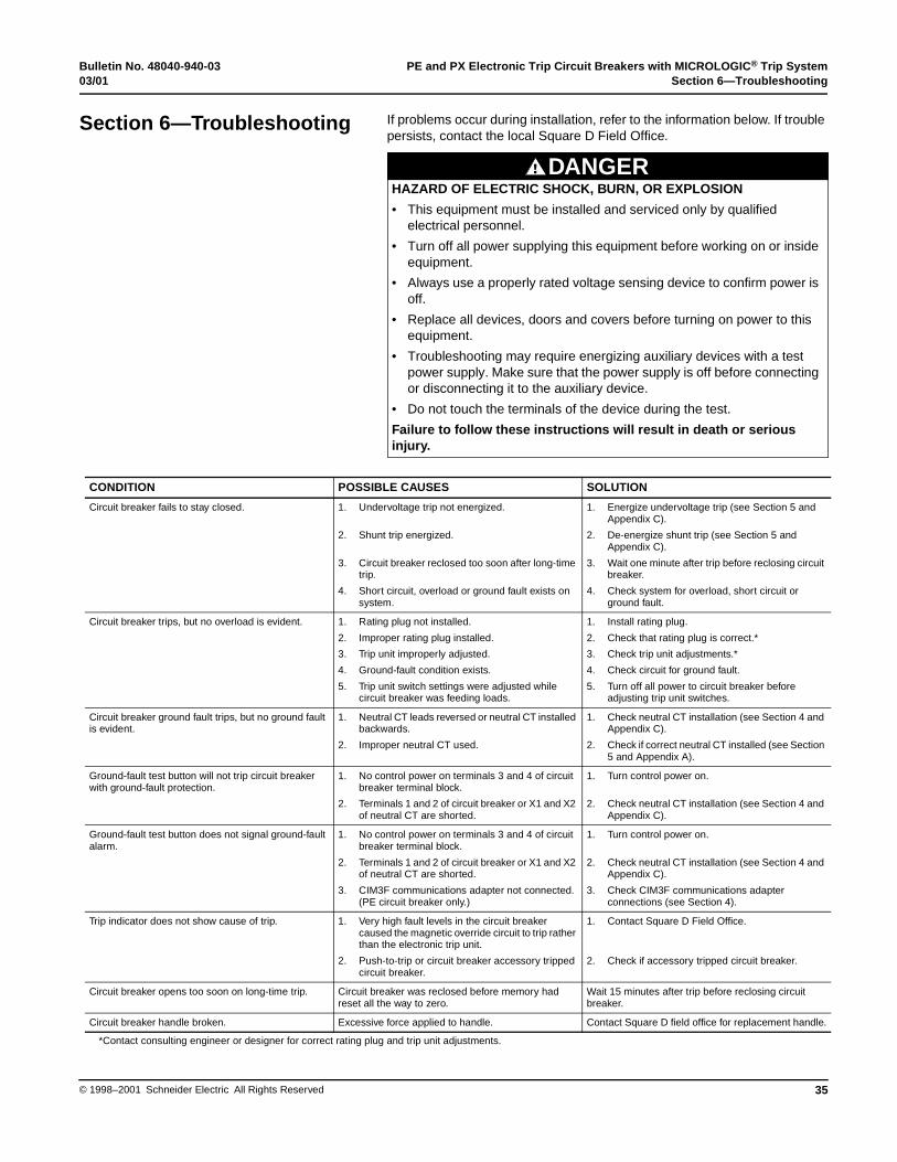
Bulletin No. 48040-940-03 PE and PX Electronic Trip Circuit Breakers with MICROLOGIC® Trip System03/01 Section 6—Troubleshooting
35© 1998–2001 Schneider Electric All Rights Reserved
If problems occur during installation, refer to the information below. If trouble persists, contact the local Square D Field Office.
Section 6—Troubleshooting
CONDITION POSSIBLE CAUSES SOLUTION
Circuit breaker fails to stay closed. 1. Undervoltage trip not energized.
2. Shunt trip energized.
3. Circuit breaker reclosed too soon after long-time trip.
4. Short circuit, overload or ground fault exists on system.
1. Energize undervoltage trip (see Section 5 and Appendix C).
2. De-energize shunt trip (see Section 5 and Appendix C).
3. Wait one minute after trip before reclosing circuit breaker.
4. Check system for overload, short circuit or ground fault.
Circuit breaker trips, but no overload is evident. 1. Rating plug not installed.
2. Improper rating plug installed.
3. Trip unit improperly adjusted.
4. Ground-fault condition exists.
5. Trip unit switch settings were adjusted while circuit breaker was feeding loads.
1. Install rating plug.
2. Check that rating plug is correct.*
3. Check trip unit adjustments.*
4. Check circuit for ground fault.
5. Turn off all power to circuit breaker before adjusting trip unit switches.
Circuit breaker ground fault trips, but no ground fault is evident.
1. Neutral CT leads reversed or neutral CT installed backwards.
2. Improper neutral CT used.
1. Check neutral CT installation (see Section 4 and Appendix C).
2. Check if correct neutral CT installed (see Section 5 and Appendix A).
Ground-fault test button will not trip circuit breaker with ground-fault protection.
1. No control power on terminals 3 and 4 of circuit breaker terminal block.
2. Terminals 1 and 2 of circuit breaker or X1 and X2 of neutral CT are shorted.
1. Turn control power on.
2. Check neutral CT installation (see Section 4 and Appendix C).
Ground-fault test button does not signal ground-fault alarm.
1. No control power on terminals 3 and 4 of circuit breaker terminal block.
2. Terminals 1 and 2 of circuit breaker or X1 and X2 of neutral CT are shorted.
3. CIM3F communications adapter not connected.(PE circuit breaker only.)
1. Turn control power on.
2. Check neutral CT installation (see Section 4 and Appendix C).
3. Check CIM3F communications adapter connections (see Section 4).
Trip indicator does not show cause of trip. 1. Very high fault levels in the circuit breaker caused the magnetic override circuit to trip rather than the electronic trip unit.
2. Push-to-trip or circuit breaker accessory tripped circuit breaker.
1. Contact Square D Field Office.
2. Check if accessory tripped circuit breaker.
Circuit breaker opens too soon on long-time trip. Circuit breaker was reclosed before memory had reset all the way to zero.
Wait 15 minutes after trip before reclosing circuit breaker.
Circuit breaker handle broken. Excessive force applied to handle. Contact Square D field office for replacement handle.
*Contact consulting engineer or designer for correct rating plug and trip unit adjustments.
DANGERHAZARD OF ELECTRIC SHOCK, BURN, OR EXPLOSION
• This equipment must be installed and serviced only by qualified electrical personnel.
• Turn off all power supplying this equipment before working on or inside equipment.
• Always use a properly rated voltage sensing device to confirm power is off.
• Replace all devices, doors and covers before turning on power to this equipment.
• Troubleshooting may require energizing auxiliary devices with a test power supply. Make sure that the power supply is off before connecting or disconnecting it to the auxiliary device.
• Do not touch the terminals of the device during the test.
Failure to follow these instructions will result in death or serious injury.
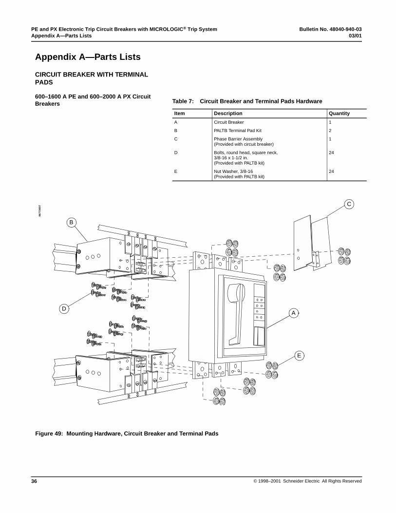
PE and PX Electronic Trip Circuit Breakers with MICROLOGIC® Trip System Bulletin No. 48040-940-03Appendix A—Parts Lists 03/01
© 1998–2001 Schneider Electric All Rights Reserved36
Appendix A—Parts Lists
CIRCUIT BREAKER WITH TERMINAL PADS
600–1600 A PE and 600–2000 A PX Circuit Breakers Table 7: Circuit Breaker and Terminal Pads Hardware
Item Description Quantity
A Circuit Breaker 1
B PALTB Terminal Pad Kit 2
C Phase Barrier Assembly(Provided with circuit breaker)
1
D Bolts, round head, square neck,3/8-16 x 1-1/2 in.(Provided with PALTB kit)
24
E Nut Washer, 3/8-16(Provided with PALTB kit)
24
Figure 49: Mounting Hardware, Circuit Breaker and Terminal Pads
A
E
B
D
C
0677
3007
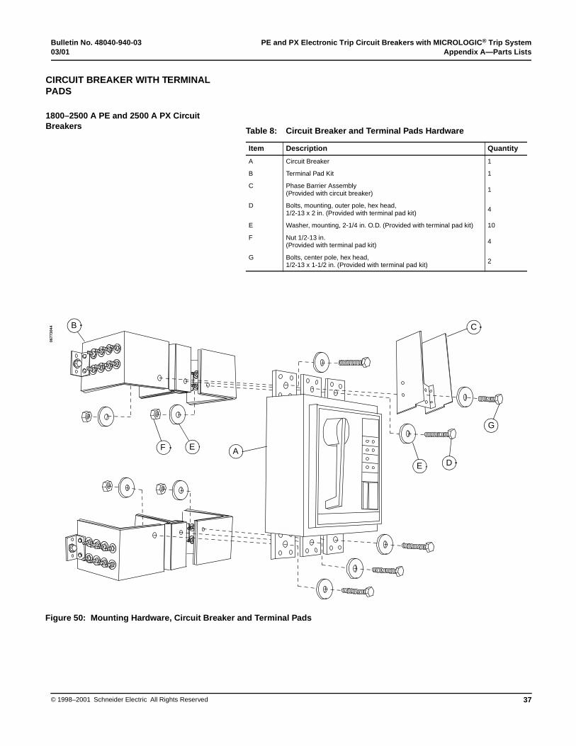
Bulletin No. 48040-940-03 PE and PX Electronic Trip Circuit Breakers with MICROLOGIC® Trip System03/01 Appendix A—Parts Lists
37© 1998–2001 Schneider Electric All Rights Reserved
CIRCUIT BREAKER WITH TERMINAL PADS
1800–2500 A PE and 2500 A PX Circuit Breakers Table 8: Circuit Breaker and Terminal Pads Hardware
Item Description Quantity
A Circuit Breaker 1
B Terminal Pad Kit 1
C Phase Barrier Assembly (Provided with circuit breaker) 1
D Bolts, mounting, outer pole, hex head,1/2-13 x 2 in. (Provided with terminal pad kit) 4
E Washer, mounting, 2-1/4 in. O.D. (Provided with terminal pad kit) 10
F Nut 1/2-13 in.(Provided with terminal pad kit) 4
G Bolts, center pole, hex head,1/2-13 x 1-1/2 in. (Provided with terminal pad kit) 2
Figure 50: Mounting Hardware, Circuit Breaker and Terminal Pads
AEF
B C
G
DE
0677
3044

PE and PX Electronic Trip Circuit Breakers with MICROLOGIC® Trip System Bulletin No. 48040-940-03Appendix A—Parts Lists 03/01
© 1998–2001 Schneider Electric All Rights Reserved38
CIRCUIT BREAKER WITH TERMINAL PADS
1800–2500 A PE and 2500 A PX Circuit Breakers
Table 9: Terminal Pad Parts
Item Description Quantity
A Terminal Pad, outer pole 2
B Terminal Pad, outer pole 2
C Terminal Pad, center pole 2
D Mounting Bracket, fiberglass 12
Bracket Mounting Hardware
E Bolt, Bracket Mounting, 1/2-13 x 1-3/8 in. hex head
12
F Washer, Bracket, flat, 1-3/8 in. O.D. 12
G Washer, Bracket, conical spring, 1-3/8 in. O.D. 12
H Nut, Bracket, hex, 1/2-13 12
Lug Mounting Hardware
I Bolt, Lug Mounting, 1/3-13 x 1-1/2 in. 48
J Washer, Lug Mounting, conical spring, 1/2-13 48
K Nut, Lug Mounting, hex, 1/2-13 48
Circuit Breaker Mounting Hardware
L Bolt, Mounting, outer pole, 1/2-13 x 2 in. 4
M Bolt, Mounting, center pole, 1/2-13 x 1-1/2 in. 2
N Washer, Mounting, 2-1/4 in. O.D. 10
O Nut, Mounting, 1/2-13 4
Figure 51: Terminal Pads Assembly
L
B C A
N
O
M
N
IJ
K D
FE
G
H
CA
B
0677
3045

Bulletin No. 48040-940-03 PE and PX Electronic Trip Circuit Breakers with MICROLOGIC® Trip System03/01 Appendix A—Parts Lists
39© 1998–2001 Schneider Electric All Rights Reserved
CATALOG NUMBERS
Table 10: Neutral Current Transformers
Circuit BreakerFrame Rating
Neutral Current Transformer Catalog Number
1200 Ampere PE12CT2 Series 3
1600 Ampere PE16CT2 Series 3
2000 Ampere PE20CT2 Series 3
2500 Ampere PE25CT2 Series 3
Table 11: Rating Plugs
Catalog Number Multiplier
ARP040 0.400
ARP050 0.500
ARP056 0.563
ARP058 0.583
ARP060 0.600
ARP063 0.625
ARP067 0.667
ARP070 0.700
ARP075 0.750
ARP080 0.800
ARP083 0.833
ARP088 0.875
ARP090 0.900
ARP100 1.000

PE and PX Electronic Trip Circuit Breakers with MICROLOGIC® Trip System Bulletin No. 48040-940-03Appendix B—Dimentional Drawings 03/01
© 1998–2001 Schneider Electric All Rights Reserved40
Figure 52: Neutral Current Transformer
Appendix B—Dimensional Drawings
NEUTRAL CURRENT TRANSFORMER
3.87[98]
8.50[216]
4.23[107]
2.38[61]
0.56[14]
0.44[11]
2.25[57]
1.50[38]
0.75[19]
0.62[16]
1.37[35]
2.13[54]
2.75[70]
0.40[10]
2 Dia.
8 Dia.
0677
3046
Dimensions: in.[mm]
3.06[78]
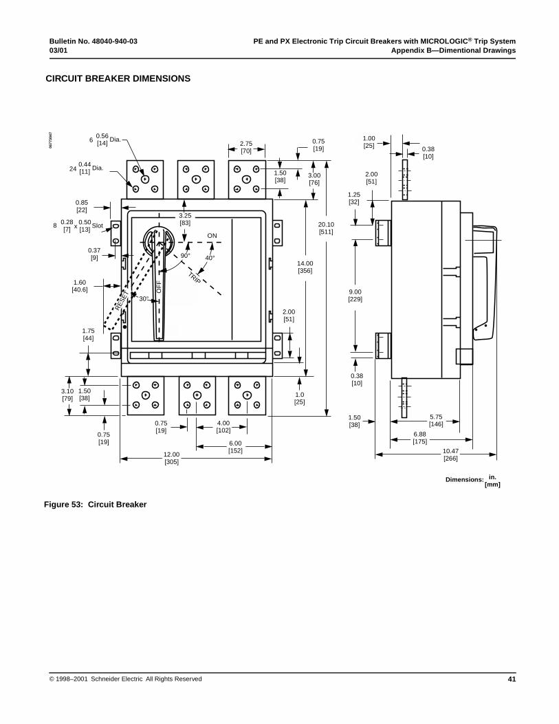
Bulletin No. 48040-940-03 PE and PX Electronic Trip Circuit Breakers with MICROLOGIC® Trip System03/01 Appendix B—Dimentional Drawings
41© 1998–2001 Schneider Electric All Rights Reserved
CIRCUIT BREAKER DIMENSIONS
Figure 53: Circuit Breaker
0.56[14] 0.75
[19]
3.00[76]
0.85[22]
0.37[9]
1.60[40.6]
1.75[44]
0.75[19]
1.50[38]
0.75[19]
2.00[51]
1.0[25]
1.50[38]
1.00[25] 0.38
[10]
2.00[51]
1.25[32]
0.38[10]
1.50[38]
2.75[70]
Dia.
0.44[11] Dia.
0.28[7]
Slot0.50[13]x
3.10[79]
12.00[305]
4.00[102]
6.00[152]
20.10[511]
14.00[356]
ON
TRIP
RE
SET
30°
40°90°
OF
F
9.00[229]
5.75[146]
6.88[175]
10.47[266]
0677
3047
Dimensions: in.[mm]
6
24
8
3.25[83]

PE and PX Electronic Trip Circuit Breakers with MICROLOGIC® Trip System Bulletin No. 48040-940-03Appendix B—Dimentional Drawings 03/01
© 1998–2001 Schneider Electric All Rights Reserved42
CIRCUIT BREAKER WITH TERMINAL PADS
600–1600 A PE and 600–2000 A PX Circuit Breakers
Figure 54: Circuit Breaker Mounted on Terminal Pads
D
33.50[851]
32.25[819]
17.62[448]
14.10[358]
0.50[13]
4.59[117]
32.58[828]
3.59[91]
9.24[235]
1.75[44]
7.00[178]
16.12[410]
0.437[11]
Push-to-trip Button
26.10[663]
8.11[210]
1.20[30]
16.55[420]
Mounting Plane
6.08[154]
FrontSupport
0.13[3]1.12
[28]13.33[340]
0.12[3]
0.88[22]
Rear Support
1.00[25]
Dia.6 x
Max.
0677
3048
Dimensions: in.[mm]
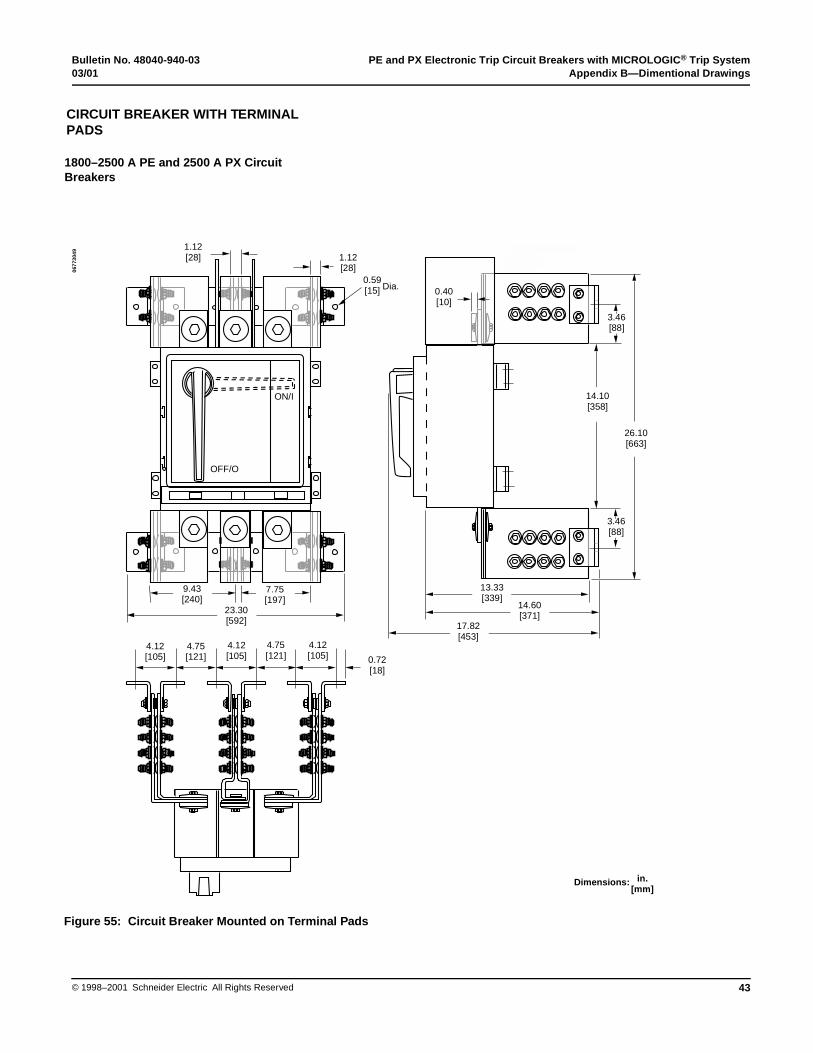
Bulletin No. 48040-940-03 PE and PX Electronic Trip Circuit Breakers with MICROLOGIC® Trip System03/01 Appendix B—Dimentional Drawings
43© 1998–2001 Schneider Electric All Rights Reserved
CIRCUIT BREAKER WITH TERMINAL PADS
1800–2500 A PE and 2500 A PX Circuit Breakers
Figure 55: Circuit Breaker Mounted on Terminal Pads
1.12[28] 1.12
[28]0.59[15]
ON/I
4.12[105] 0.72
[18]
3.46[88]
3.46[88]
0.40[10]
9.43[240]
7.75[197] 14.60
[371]
13.33[339]
26.10[663]
14.10[358]
Dia.
17.82[453]
23.30[592]
4.75[121]
4.12[105]
4.75[121]
4.12[105]
OFF/O
0677
3049
Dimensions: in.[mm]
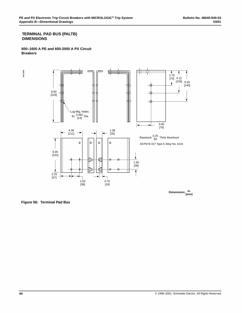
PE and PX Electronic Trip Circuit Breakers with MICROLOGIC® Trip System Bulletin No. 48040-940-03Appendix B—Dimentional Drawings 03/01
© 1998–2001 Schneider Electric All Rights Reserved44
TERMINAL PAD BUS (PALTB) DIMENSIONS
600–1600 A PE and 600-2000 A PX Circuit Breakers
Figure 56: Terminal Pad Bus
4.38[111]
1.38[35]
6.00[152]
1.50[38]
1.50[38]
0.75[19]
2.25[57]
5.50[140]
4.12[105]
8.50[216]
Lug Mtg. Holes0.562[14]
3x Dia.
Rawstock:0.25[6] Thick Aluminum
ASTM B-317 Type 5 Alloy No. 6101
0677
3050
Dimensions: in.[mm]
2.75[70]
3.00[76]
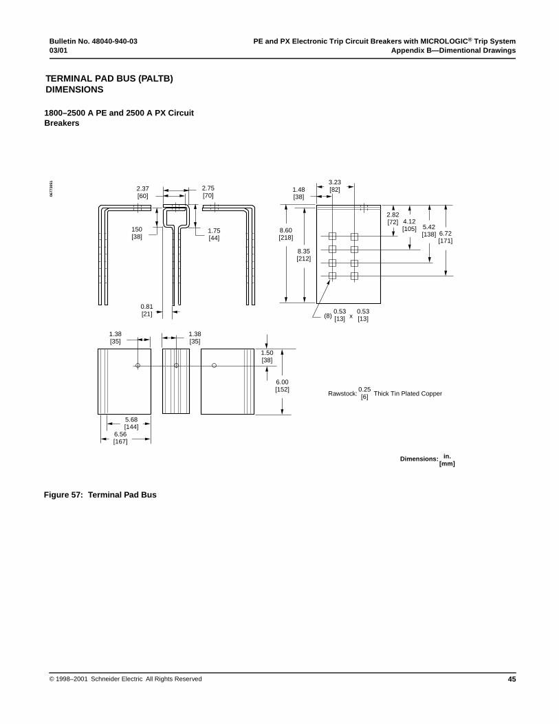
Bulletin No. 48040-940-03 PE and PX Electronic Trip Circuit Breakers with MICROLOGIC® Trip System03/01 Appendix B—Dimentional Drawings
45© 1998–2001 Schneider Electric All Rights Reserved
TERMINAL PAD BUS (PALTB) DIMENSIONS
1800–2500 A PE and 2500 A PX Circuit Breakers
Figure 57: Terminal Pad Bus
Rawstock:0.25[6] Thick Tin Plated Copper
2.37[60]
x
2.75[70]
150[38]
1.75[44]
0.81[21]
1.38[35]
1.38[35]
1.50[38]
0.53[13]
1.48[38]
(8)0.53[13]
5.68[144]
8.60[218]
8.35[212]
2.82[72] 4.12
[105] 5.42[138] 6.72
[171]
6.00[152]
3.23[82]
6.56[167]
0677
3051
Dimensions: in.[mm]

PE and PX Electronic Trip Circuit Breakers with MICROLOGIC® Trip System Bulletin No. 48040-940-03Appendix C—Wiring Diagrams 03/01
© 1998–2001 Schneider Electric All Rights Reserved46
Figure 58: Shunt Trip
Figure 59: Undervoltage Trip
Figure 60: Auxiliary Switch
Figure 61: Alarm Switch
Appendix C—Wiring Diagrams
SHUNT TRIPCircuit Breaker
AccessoryField Leads
Momentary
Vac
0677
3052
UNDERVOLTAGE TRIP
AccessoryField Leads
From Line Power
Circuit Breaker Circuit Breaker
Push-to-openSwitch
For Emergency Release
AB
C
N
AB
C
N
AB
C
N
AB
C
N
0677
3053
AUXILIARY SWITCHA B C
A
AccessoryField Leads
Circuit Breaker ClosedLight A “ON”
Light B “ON”Circuit Breaker Open/Tripped
BCom
A
B
POWER
0677
3054
ALARM SWITCH A B C
AccessoryField Leads
Power
Alarm
Circuit Breaker TrippedAlarm Circuit Energized
0677
3055
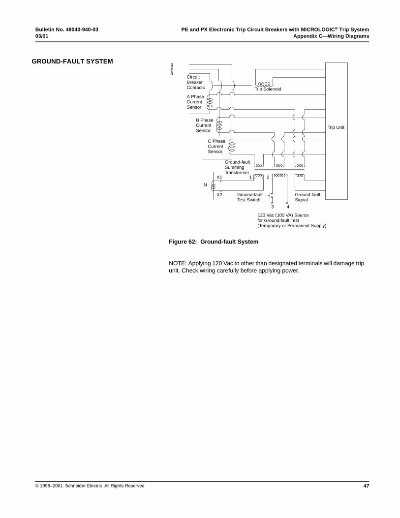
Bulletin No. 48040-940-03 PE and PX Electronic Trip Circuit Breakers with MICROLOGIC® Trip System03/01 Appendix C—Wiring Diagrams
47© 1998–2001 Schneider Electric All Rights Reserved
Figure 62: Ground-fault System
NOTE: Applying 120 Vac to other than designated terminals will damage trip unit. Check wiring carefully before applying power.
GROUND-FAULT SYSTEM
Trip Unit
CircuitBreakerContacts
A Phase Current Sensor
Trip Solenoid
Ground-faultSignal
Ground-faultTest Switch
120 Vac (100 VA) Sourcefor Ground-fault Test(Temporary or Permanent Supply)
B Phase Current Sensor
C Phase Current Sensor
N
X1
X2
1 2
Ground-faultSummingTransformer
3 4
0677
3056

PE and PX Electronic Trip Circuit Breakers with MICROLOGIC® Trip System Bulletin No. 48040-940-03Appendix C—Wiring Diagrams 03/01
© 1998–2001 Schneider Electric All Rights Reserved48
Figure 63: Zone-selective Restraint: LE, ME and NE Circuit Breakers
For maximum immunity to electrical noise:
1. Use shielded pair cable or twisted pair cable, 18–14 AWG wire (1–2.5 mm2), approximately one turn per inch, between circuit breakers.
2. Route restraint lines away from power cable or other sources of electrical noise.
3. DO NOT exceed 1000 ft. (305 m) of restraint wires between circuit breakers without use of Restraint Interface Module (Cat. No. RIM32).
For terminal block wiring use one or two #18 AWG (1 mm2) wires or one #14 AWG (2.5 mm2) wire.
Torque wire binding screws to 5–10 lb-in (0.6–1.1 N•m).
NOTE: Thermal-magnetic circuit breakers with ground-fault module restrain only on ground-fault function. Restraint wiring on ground-fault module is the same as ground-fault restraint system shown above.
Use RIM32 to interface between MICROLOGIC trip unit and the ground sensor system relay.
ZONE-SELECTIVE INTERLOCKING (PE CIRCUIT BREAKER ONLY)
SHORT TIMERESTRAINT
The diagram shows short-timefunction and ground-fault functionrestrained simultaneously. To restrain them independently, run a separate wire for each functionbetween devices.
Short-timeRestraint
SEMain
Ground-faultRestraint
INOUT
INOUT
COM
Short-timeRestraint
NEFeeder
Ground-faultRestraint
INOUT
INOUT
COM
Short-timeRestraint
MEBranch
Ground-faultRestraint
INOUT
INOUT
COM
Short-timeRestraint
LEFeeder
Ground-faultRestraint
INOUT
INOUT
COM
Ground-fault orShort-time RestraintSignal from ME to NE
Ground-fault orShort-time RestraintSignal fromDownstream Circuit Breaker
Ground-fault orShort-time RestraintSignal from LE and/or NE to SE
0677
3057
HAZARD OF TRIP UNIT DAMAGE
Do not hi-pot test zone-select restraint input or output leads.
Failure to follow this instruction can result in equipment damage.
CAUTION
Bulletin No. 48040-940-03 PE and PX Electronic Trip Circuit Breakers with MICROLOGIC® Trip System03/01 Glossary of Terms and Acronyms
49© 1998–2001 Schneider Electric All Rights Reserved
accessory (device) = an electrical or mechanical device that performs a secondary or minor function apart from overcurrent protection.
AIC (AIR) = see AIR.
AIR (ampere interrupting rating) = the highest current at rated voltage that an overcurrent protective device is intended to interrupt under specified test conditions (NEC).
alarm switch (bell alarm) = see overcurrent trip switch.
ambient temperature rating = temperature at which the continuous current rating (handle rating) of a circuit breaker is based; the temperature of the air immediately surrounding the circuit breaker which can affect the thermal (overload) tripping characteristics of thermal-magnetic circuit breakers. Electronic trip circuit breakers, however, are insensitive to normal (-20° to 50°C) ambient conditions.
ammeter/trip indicator (local current meter/trip indicator) = a module that mounts directly to the circuit breaker trip unit. The ammeter (current meter) reports rms phase and ground-fault current values as seen by the trip unit. Current values are displayed one phase at a time. The trip indicator displays whether the circuit breaker tripped due to an overload, short-circuit or ground-fault condition.
ampere rating = see continuous current rating.
auxiliary switch = a switch mechanically operated by the main device for signaling, interlocking, or other purposes.
bell alarm = see overcurrent trip switch.
branch circuit = the circuit conductor between the final overcurrent device protecting the circuit and the outlet(s).
circuit breaker = a device designed to open and close a circuit by non-automatic means and to open the circuit automatically on an overcurrent without damage to itself when properly applied within its rating.
circuit breaker frame = (1) the circuit breaker housing which contains the current carrying components, the current sensing components, and the tripping and operating mechanism. (2) that portion of an interchangeable trip molded case circuit breaker remaining when the interchangeable trip unit is removed.
coil clearing switch = a mechanically-operated switch in series with the coil of a shunt trip device which breaks the coil current when the circuit breaker opens.
continuous current rating (handle rating) = the designated rms alternating current in amperes which a device or assembly will carry continuously in free air without tripping or exceeding temperature limits.
continuous load = a load where the maximum current on the circuit is expected to continue.
CSA = Canadian Standards Association.
CT = current transformer.
current path (of a circuit breaker) = the current-carrying conductors within a circuit breaker between, and including, line and load terminations.
current rating = see continuous current rating.
Glossary of Terms and Acronyms
PE and PX Electronic Trip Circuit Breakers with MICROLOGIC® Trip System Bulletin No. 48040-940-03Glossary of Terms and Acronyms 03/01
© 1998–2001 Schneider Electric All Rights Reserved50
current transformer (current sensor) (CT) = an instrument to measure current, encircling a conductor carrying the current to be measured or controlled.
electrical operator (motor operator) = an electrical controlling device which is used to open and close a circuit breaker or switch and reset a circuit breaker.
electronic trip circuit breaker = a circuit breaker which uses current sensors and electronic circuitry to sense, measure and respond to current levels.
frame size = the maximum continuous current which the circuit breaker frame is capable of carrying without exceeding allowable temperature rise.
frequency = the number of cycles per second for an alternating current system.
frequency rating = the range of frequencies within which a product can be applied.
ground fault = an unintentional current path, through ground, back to the source.
ground-fault delay = the length of time the circuit breaker trip unit will delay before initiating a trip signal to the circuit breaker after a ground fault has been detected.
ground-fault module = an electronic accessory used in combination with thermal-magnetic circuit breakers to provide branch circuit ground-fault protection and ground-fault indication.
ground-fault pickup = the level of ground-fault current at which the trip system begins timing.
handle rating = continuous current rating.
instantaneous pickup = the current level at which the circuit breaker will trip with no intentional time delay.
instantaneous trip = (as applied to circuit breakers) a qualifying term indicating that no delay is purposely introduced in the tripping action of the circuit breaker during short-circuit conditions.
integral ground-fault protection = equipment ground-fault protection on grounded neutral systems provided by components internal to the circuit breaker.
interrupting rating = the highest current at rated voltage available at the incoming terminals of the circuit breaker. When the circuit breaker can be used at more than one voltage, the interrupting rating will be shown on the circuit breaker for each voltage level. The interrupting rating of a circuit breaker must be equal to or greater than the available short-circuit current at the point at which the circuit breaker is applied to the system.
inverse time = a qualifying term indicating there is purposely introduced a delay in the tripping action of the circuit breaker, which delay decreases as the magnitude of the current increases.
I2t IN = an inverse time delay characteristic.
I2t OUT = a constant time delay characteristic.

Bulletin No. 48040-940-03 PE and PX Electronic Trip Circuit Breakers with MICROLOGIC® Trip System03/01 Glossary of Terms and Acronyms
51© 1998–2001 Schneider Electric All Rights Reserved
let-through = an expression related to energy (measured in ampere-squared seconds) which passes through an overcurrent protective device during an interruption.
LI (dual trip device) = a combination of adjustable trip functions including long-time ampere rating, long-time delay, and instantaneous pickup.
LIG (dual with ground trip device) = a combination of adjustable trip functions including long-time ampere rating, long-time delay, instantaneous pickup, ground-fault pickup and ground-fault delay.
local current meter = ammeter/trip indicator.
long-time ampere rating = an adjustment which, in combination with the installed rating plug, establishes the continuous current rating of a full-function electronic trip circuit breaker.
long-time delay = the length of time the circuit breaker will carry a sustained overcurrent (greater than the long-time pickup) before initiating a trip signal.
long-time pickup = the current level at which the circuit breaker long-time delay function begins timing.
LS = a combination of adjustable trip functions including long-time ampere rating, long-time delay, short-time pickup, short-time delay and a defeatable instantaneous pickup.
LSG = a combination of adjustable trip functions including long-time ampere rating, long-time delay, short-time pickup, short-time delay, defeatable instantaneous pickup, ground-fault pickup and ground-fault delay.
LSIG = a combination of adjustable trip functions including long-time ampere rating, long-time delay, short-time pickup, short-time delay, defeatable instantaneous pickup, ground-fault pickup and ground-fault delay.
MICROLOGIC = the Square D family of electronic trip systems available on molded case circuit breakers, insulated case circuit breakers and low-voltage power circuit breakers.
molded case circuit breaker = a circuit breaker which is assembled as an integral unit in a supportive and enclosed housing of insulating material.
molded case switch = a device designed to open and close a circuit by non-automatic means that is not intended to provide overcurrent protection.
neutral current transformer = a current transformer which encircles the neutral conductor; required on circuit breakers with ground-fault protection, when applied on a grounded system.
OTS = overcurrent trip switch (alarm switch, bell alarm).
overcurrent = any current in excess of the rated continuous current of equipment or the ampacity of a conductor.
overcurrent trip element = a device which detects an overcurrent and transmits the energy necessary to open the circuit automatically.
overcurrent trip switch = a mechanically-operated switch which indicates when a circuit breaker has tripped due to overcurrent conditions.
overload delay = the length of time the circuit breaker will carry a sustained low-level overcurrent before initiating a trip signal.
peak current sensing = a method of determining the current by means of detecting the current peaks.
PE and PX Electronic Trip Circuit Breakers with MICROLOGIC® Trip System Bulletin No. 48040-940-03Glossary of Terms and Acronyms 03/01
© 1998–2001 Schneider Electric All Rights Reserved52
peak let-through = the maximum peak current in a circuit during an overcurrent condition.
push-to-trip button = a button for manually tripping the circuit breaker.
rating plug = a component which plugs into the full-function electronic trip unit, establishing the maximum continuous current rating of the circuit breaker.
residual ground-fault sensing = a means of providing equipment ground-fault protection utilizing sensors on each individual phase.
restraint interface module (RIM) = a component which allows zone-selective interlocking communication between Square D full-function electronic trip systems, add-on ground-fault modules and zero-sequence ground-fault relays.
RIM = restraint interface module.
rms = root-mean-square.
rms current sensing = a method of determining the true rms current of sinusoidal and non-sinusoidal waveforms.
sensor ampere rating = the size of the current transformer for rated output.
short-circuit delay = the length of time the circuit breaker will carry a short circuit (current greater than the short-circuit pickup) before initiating a trip signal.
short-circuit pickup = the current level at which the circuit breaker short-circuit delay function begins timing.
short-time delay = the length of time the circuit breaker will carry a short circuit (current greater than the short-time pickup) before initiating a trip signal.
short-time pickup = the current level at which the circuit breaker short-time delay function begins timing.
shunt trip = an accessory which trips the circuit breaker from a remote location using an external voltage source.
STD = short-time delay.
terminal block = the connections for control wiring.
thermal-magnetic circuit breaker = a general purpose term for circuit breakers that use bimetals and electromagnetic assemblies to provide both thermal and magnetic overcurrent protection.
trip button = a button used to manually trip the circuit breaker.
trip indicator = a module that mounts directly to the circuit breaker trip unit that displays whether the circuit breaker tripped due to an overload, a short-circuit or a ground-fault condition.
trip indicator reset = a button on the trip indicator module used to reset the trip indicator.
trip system = a system which consists of a MICROLOGIC trip unit and current transformers.
trip unit = a programmable microprocessor-based device which measures and times current flowing through the circuit breaker and initiates a trip signal when appropriate.
UL = Underwriters Laboratories Inc.
Bulletin No. 48040-940-03 PE and PX Electronic Trip Circuit Breakers with MICROLOGIC® Trip System03/01 Glossary of Terms and Acronyms
53© 1998–2001 Schneider Electric All Rights Reserved
undervoltage trip (UVR) = an accessory which trips the circuit breaker automatically when the monitored circuit voltage falls below a predetermined percentage of its specified value.
UVR = undervoltage trip.
zero-sequence ground-fault sensing = a means of providing equipment ground-fault protection utilizing an external sensor (surrounding all phase and neutral conductors).
zone-selective interlocking (ZSI) = a communication capability between electronic trip systems and ground-fault relays which permits a short circuit or ground fault to be isolated and cleared by the nearest upstream device with no intentional time delay.
ZSI = zone-selective interlocking.

©1998–2001 Schneider Electric All Rights Reserved54
PE and PX Electronic Trip Circuit Breakers with MICROLOGIC® Trip System Bulletin No. 48040-940-03Index 03/01
Index AAccessories
alarm switchoperation ..................................................32wiring .......................................................46
ammeter/trip indicator ......................................34auxiliary switch
operation ..................................................31wiring .......................................................46
communications adapter ..................................32installation ........................................................24restraint interface module ................................32shunt trip
operation ..................................................31wiring .......................................................31
trip indicator .....................................................33troubleshooting ................................................35undervoltage trip
operation ..................................................31wiring .......................................................46
universal test set ..............................................33
Alarm switchoperation ..........................................................46wiring ...............................................................46
Ammeter/trip indicator ....................................... 17, 34
Auxiliary switchoperation ..........................................................31wiring ...............................................................46
BBus bar connections
1800–2500 A PE circuit breakers ....................102500 A PX circuit breakers ..............................10600–1600 A PE circuit breakers ........................7
CCable connections
1800–2500 A PE circuit breakers ....................102500 A PX circuit breakers ..............................10600–1600 A PE circuit breakers ........................7600–2000 A PX circuit breakers ........................7
Catalog numbersneutral current transformer ..............................39rating plugs ......................................................39
CIM3F. See Communications adapter
Circuit breakeraccessories. See Accessoriesdimensions .......................................................41dimensions with terminal pads
1800–2500 A PE circuit breakers ............432500 A PX circuit breakers ......................43600–1600 A PE circuit breakers ..............42600–2000 A PX circuit breakers ..............42
Identification .......................................................5inspection ...........................................................6
installation1800–2500 A PE circuit breakers ............102500 A PX circuit breakers ......................10600–1600 A PE circuit breakers ................7600–2000 A PX circuit breakers ................7
parts list1800–2500 A PE circuit breakers ............372500 A PX circuit breakers ......................37600–1600 A PE circuit breakers ..............36600–2000 A PX circuit breakers ..............36
removal ............................................................15
Communications adapter .........................................32operation ..........................................................32wiring ...............................................................26
Control wiringcommunications adapter ..................................25ground-fault alarm ............................................25ground-fault protection .....................................25location ..............................................................6POWERLOGIC system ....................................26routing ..............................................................28zone-selective interlocking ...............................27
Coordination study ...................................................26
Coordination, system ...............................................26
CT. See Neutral current transformer
Current rating ...........................................................16
Current transformer, neutral. See Neutral current transformers.
DDimensions
circuit breaker with terminal pads1800–2500 A PE circuit breakers ............432500 A PX circuit breakers ......................43600–1600 A PE circuit breakers ..............42600–2000 A PX circuit breakers ..............42
circuit breaker, front view .................................41neutral current transformer ..............................40terminal pad bus
1800–2500 A PE circuit breakers ............452500 A PX circuit breakers ......................45
EElectrical accessories. See Accessories
Electronic trip unit. See Trip unit
FFrame size .................................................................5
GGround-fault
alarmdescription ...............................................17function ....................................................22wiring .......................................................25

55© 1998–2001 Schneider Electric All Rights Reserved
Bulletin No. 48040-940-03 PE and PX Electronic Trip Circuit Breakers with MICROLOGIC® Trip System03/01 Index
protectiondescription ...............................................17trip function ........................................20, 22wiring .......................................................25zone-selective interlocking ......................26
test featuredescription ...............................................18testing ......................................................28wiring .......................................................25
trip functionfull-function trip unit .................................22standard trip unit ......................................20
wiring diagram .................................................47
HHardware. See Parts lists
IIdentification ...............................................................5
Inspection ..................................................................6
Installation1800–2500 A PE circuit breakers ....................102500 A PX circuit breakers ..............................10600–1600 A PE circuit breakers ........................7600–2000 A PX circuit breakers ........................7
Instantaneous trip functionfull-function trip unit .........................................22standard trip unit ..............................................20
Integral ground-fault. See Ground-fault
Interrupting ratings .....................................................5
LLong-time trip function
full-function trip unit .........................................21standard trip unit ..............................................19
Lug information ....................................................8, 13
MMemory feature, trip unit ..........................................17
MICROLOGIC full-function trip system ....................16
MICROLOGIC standard trip system ........................16
Mounting kit. See Terminal pads
NNeutral CT. See Neutral current transformer
Neutral current transformercatalog numbers ..............................................39dimensions ......................................................40wiring ...............................................................25
PPALTB. See Terminal pads
Parts lists
circuit breaker with terminal pads1800–2500 A PE circuit breakers ............ 372500 A PX circuit breakers ...................... 37600–1600 A PE circuit breakers .............. 36600–2000 A PX circuit breakers .............. 36
neutral current transformers ............................ 39rating plugs ...................................................... 39terminal pads
1800–2500 A PE circuit breakers ............ 382500 A PX circuit breakers ...................... 38600–1600 A PE circuit breakers .............. 36600–2000 A PX circuit breakers .............. 36
POWERLOGIC system ........................................... 25
RRating
100% ................................................................. 5current rating ................................................... 16interrupting ......................................................... 5
Rating plug .............................................................. 16catalog number ................................................39
Receving inspection ..................................................6
Removal .................................................................. 15
Restraint interface module .......................... 27, 32, 48
RIM32. See Restraint interface module
SSeal trip unit ............................................................. 30
Sensors. See Current sensors
Short-time trip functionfull-function trip unit ......................................... 21standard trip unit .............................................. 19zone-selective interlocking .............................. 27
Shunt tripoperation .......................................................... 31wiring ............................................................... 46
Switch, alarmoperation .......................................................... 32
Switch, auxiliaryoperation .......................................................... 31wiring ............................................................... 46
System coordination ................................................26
System coordination study ...................................... 26
TTerminal location ..................................................... 24
Terminal pads ............................................................ 6bus dimensions
1800–2500 A PE circuit breakers ............ 452500 A PX circuit breakers ...................... 45
dimensions with circuit breaker1800–2500 A PE circuit breakers ............ 432500 A PX circuit breakers ...................... 43600–1600 A PE circuit breakers .............. 42

©1998–2001 Schneider Electric All Rights Reserved56
PE and PX Electronic Trip Circuit Breakers with MICROLOGIC® Trip System Bulletin No. 48040-940-03Index 03/01
600–2000 A PX circuit breakers ..............42installation
1800–2500 A PE circuit breakers ............102500 A PX circuit breakers ......................10600–1600 A PE circuit breakers ................7600–2000 A PX circuit breakers ................7
parts list1800–2500 A PE circuit breakers ......37, 382500 A PX circuit breakers ................37, 38600–1600 A PE circuit breakers ..............36600–2000 A PX circuit breakers ..............36
Test ground-fault feature .........................................28
Transformer, neutral current ..............................25, 40
Trip indicator ............................................................33
Trip unitadjustability
description .........................................16, 23setting functions .......................................23
ammeter/trip indicator ......................................17ampere rating ..................................................16functions description
full-function trip unit .................................21standard trip unit ......................................19
integral ground-fault detection .........................17memory feature ...............................................17sealing .............................................................30setting functions ...............................................23test ground-fault feature ..................................28trip characteristics ............................................18
Troubleshootingcircuit breaker ..................................................35
UUndervoltage trip
adjustable delay ...............................................31operation ..........................................................31wiring .........................................................33, 46
Universal test set .....................................................33
WWiring diagrams
alarm switch .....................................................46auxiliary switch ................................................46ground-fault .....................................................47shunt trip ..........................................................46undervoltage trip ..............................................46zone-selective interlocking ..............................48
Wiring, control power ...............................................46
ZZone-selective interlock
allowable combinations ...................................26
Zone-selective interlocking ......................................26activating .........................................................27wiring ...............................................................48
ZSI. See Zone selective interlocking

57© 1998–2001 Schneider Electric All Rights Reserved
Bulletin No. 48040-940-03 PE and PX Electronic Trip Circuit Breakers with MICROLOGIC® Trip System03/01 Index

©1998–2001 Schneider Electric All Rights Reserved58
PE and PX Electronic Trip Circuit Breakers with MICROLOGIC® Trip System Bulletin No. 48040-940-03Index 03/01

Bulletin No. 48040-940-03 PE and PX Electronic Trip Circuit Breakers with MICROLOGIC® Trip System03/01
59© 1998–2001 Schneider Electric All Rights Reserved

Electrical equipment should be serviced only by qualified personnel. No responsibility is assumed by Schneider Electric for any consequences arising out of the use of this material. This document is not intended as an instruction manual for untrained persons.
Bulletin No. 48040-940-03 K279 03/2001 Replaces 48040-940-03 J420 dated 3/98.
PE and PX Electronic Trip Circuit Breakers with MICROLOGIC® Trip System
Square D CompanyPO Box 30693700 Sixth St SWCedar Rapids IA 52406-3069 USA1-888-SquareD (1-888-778-2733)www.SquareD.com