pdm for masses - white paper - vibration · ultrasonic inspection program would be once their...
TRANSCRIPT

Airborne Ultrasound – Predictive Maintenance for the Masses 1 © Copyright 2005 – SDT North America, All Rights Reserved
Ultrasonic Excellence
www.sdtnorthamerica.com
Airborne Ultrasound: Predictive Maintenance for the Masses Allan Rienstra, SDT North America
The phenomenal rise in popularity of Airborne Ultrasound for use in predictive maintenance
programs is attributed to three factors; ease of use, versatility, and low implementation cost.
Once considered a companion technology to core predictive tools such as vibration and infrared
analysis, we now see the emergence of stand alone ultrasound inspection programs as standard
practice for maintenance departments around the globe. Indeed ultrasound is now considered a
front-line defence system in the everyday battle for manufacturing uptime. Airborne Ultrasound is
Predictive Maintenance for the Masses.
Like any advanced inspection and monitoring technology, purchasing the hardware is just one of
several steps involved in establishing a program that works. An effective ultrasound inspection
program includes a planned pre-investment strategy to ensure results right out of the box. Your
strategy includes identifying which applications are most important for your facility, how
inspections will be carried out, and how your results will be benchmarked. It addresses issues
such as certification training and program leadership as well as goal setting and program
evaluation. Without a sound strategy in place your ultrasound program may not have the long-
term effect you desire.
Program Implementation Establishing this strategy is problematic for maintenance departments already stretched thin by
budget cuts or manages to exist in a “putting out fires first” mentality. For example, assigning
manpower to collect ultrasonic route data is a tremendous hurdle to overcome initially, but is
more realistically achieved if implementation procedures are put in place first. An implementation
strategist assists in setting up an ultrasound inspection program custom designed to suit the
needs and goals of your individual facility. On-site consultants help you justify the implementation
of your program by:
• Educating your personnel on the basics of ultrasonic inspection and data collection
• Working with you to identify all the applications that apply to your plant
• Conducting plant tours to identify data collection points and logical route creation
• Writing procedures and manuals for inspectors
• Providing on-site Certification Training
• Establishing a corporate pilot program at a single facility
• Taking initial readings to establish baseline data and commitment to procedures
Airborne Ultrasound – Predictive Maintenance for the Masses 2 © Copyright 2005 – SDT North America, All Rights Reserved
Ultrasonic Excellence
www.sdtnorthamerica.com
• Establishing short-term and long-term goals for each application
• Creating ways to benchmark the program’s benefits
• Following up and reviewing goals to keep the program on-track
Companies that recognize the value in maintaining an effective ultrasound inspection program
based on the points outlined above have already invested in an on-site implementation strategist
to help them meet and keep their goals.
Mass Appeal Predictive Maintenance Managers are attracted to airborne ultrasound inspection because its a
technology that is easy to use, has boundless versatility, and is low cost relative to other
predictive technologies. The most common uses include leak detection, condition monitoring,
and condition-based acoustic lubrication of bearings. Additionally, specific industries monitor
thousands of steam traps and pinpoint in-leakage to boilers, condensers, and heat exchangers.
Still others tie ultrasonic inspection and infrared scanning together for a more complete predictive
maintenance of their electrical substations and switchgear.
Easy To Use Ease of use does not necessarily equate with simplicity. The inner workings of an ultrasonic data
collector are complex. However quality manufacturers dedicate their resources to develop an
ergonomic logical user interface that promotes an easy to use instrument.
The basic operating principle is to detect high frequency sound pressure waves, beyond the
range of our human ears, and transform them to low frequency waves which can be heard
through noise attenuating headphones. The sound quality is maintained during this
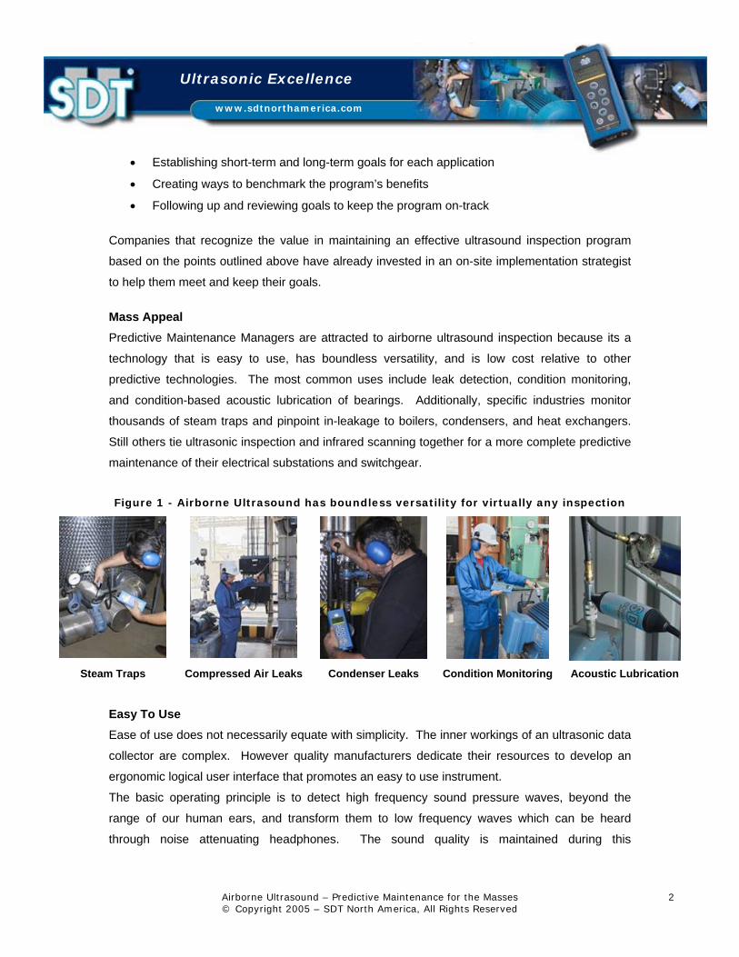
Figure 1 - Airborne Ultrasound has boundless versatility for virtually any inspection
Steam Traps Compressed Air Leaks Condenser Leaks Condition Monitoring Acoustic Lubrication

Airborne Ultrasound – Predictive Maintenance for the Masses 3 © Copyright 2005 – SDT North America, All Rights Reserved
Ultrasonic Excellence
www.sdtnorthamerica.com
transformation so what we hear in the sonic range represents the original ultrasonic source. A
bearing sounds like a bearing, a leak sound like a leak, and so forth.
The development of more technically sophisticated ultrasonic data collectors is driving the
popularity of this technology. More than just translators of sound, today’s technology provide
repeatable measurements, process data digitally from start to finish, can collect and trend
readings, and record sound files for advanced analysis and sonic visualization.
Figure 2 - Heterodyning effect
Ultrasonic Analysis is a technology that benefits EVERYONE involved in maintaining the
manufacturing process. As you have read, applications for airborne ultrasound are many, and far
reaching. Perhaps one of the biggest hurdles faced by your ultrasonic program will be scheduling
your turn to use the equipment. Ultrasonic applications will suit:
• Vibration Analysts • Maintenance Mgrs
• I/R Thermographers • Facilities Mgrs
• Lube Techs • PdM Planners
• Millwrights • Production Mgrs
• Pipe Fitters • Quality Control Mgrs Most maintenance related problems encountered at your plant can be discovered at a very early
stage through the implementation of an ultrasonic program. Traditionally excessive vibration and
thermal increases were sure indicators of a mechanical failure on the not-too-distant horizon. But

Airborne Ultrasound – Predictive Maintenance for the Masses 4 © Copyright 2005 – SDT North America, All Rights Reserved
Ultrasonic Excellence
www.sdtnorthamerica.com
we also know that microscopic changes in friction forces, detectable with ultrasonic testing long
before a machine enters critical failure, provide a bigger window of opportunity for scheduled
maintenance. By hearing problems at an earlier stage, damage is minimal and the required
maintenance is completed with less impact to the overall operation of the process.
Take a look at some of the most common maintenance applications for airborne ultrasound that
could be applied at your plant today.
• Air Leak Detection • Pump Cavitation
• Condition Monitoring • Compressor Valve Inspections
• Acoustic Lubrication • Heat Exchanger and Condenser Leaks
• Electrical Inspections • Hydraulic Systems
• Steam Systems • Tightness Control Compressed Air Leak Detection Compressed air is a top three high-cost utilities in use at your plant. Leaks are expensive, and
often ignored. Most often they can be heard with the naked ear, but are difficult to pinpoint
because of background noise. An ultrasonic detector can hear leak turbulence through the
ambient noise of the factory floor. The high frequency component of a leak is directional making
it easy to locate its source. A compressed air survey with an ultrasonic detector once per quarter
can reveal savings potential in the millions and benefit facilities managers looking to improve
efficiency and reduce costs.
Figure 3 - Conducting an air leak survey

Airborne Ultrasound – Predictive Maintenance for the Masses 5 © Copyright 2005 – SDT North America, All Rights Reserved
Ultrasonic Excellence
www.sdtnorthamerica.com
Real World Case Report – Compressed Air Leak Detection A medium sized southwestern Ontario factory makes aluminum wheels for the automotive
industry. The facilities manager was charged with the responsibility for utilities optimization,
which means he looks at any technology that can save his company money, builds a project
around the idea, and if the numbers add up the project goes ahead. Across from his desk
scrawled in bold black marker on his whiteboard were the words:
Compressed Air Savings
$140K in 6 months When asked to explain he recounted that in the 6 months since purchasing his Ultrawave 170
leak detector he calculated ongoing savings of $140,000. That’s $280,000 per year wasted to
compressed air leaks. He went on to say that based upon their company’s current profit margins
they would have to make, and sell, an additional $8,000,000 of product to compensate the
expense of compressed air leaks.
Saving $ 280,000/Year is
Like Adding $8,000,000 in Gross Revenue
Since the position of Utilities Optimization was created they looked at a lot of ways to reduce
energy costs including energy efficient lighting and motors. No other ideas met the rewards
posted by the compressed air audits and remediation. When asked what the future of their
ultrasonic inspection program would be once their compressed air system was fixed, a candid
reply followed a confident smile.
“We plan to continue our air leak surveys each quarter. The leaks we have today are the
net result of years of neglect and ignorance about true costs. Now we are educated
about the expense compressed air represents, and we know that new leaks will manifest
on their own. Leak detection is now part of our regular preventative maintenance and our
post-strategy goal is to ensure things never get back to where they were.. Our strategy
was born out of necessity, and it works. Goals were set, procedures were written, and
significant savings were documented giving us approval all the way to the CEO level.
Our next step is to analyze condition monitoring applications with ultrasound. If we can
demonstrate benefits then a program will be implemented and launched based on our
projected findings.”

Airborne Ultrasound – Predictive Maintenance for the Masses 6 © Copyright 2005 – SDT North America, All Rights Reserved
Ultrasonic Excellence
www.sdtnorthamerica.com
Condition Monitoring
Ultrasonic data collection offers a significant and necessary application for condition monitoring
production machines and trending normal operating levels to identify changes that affect healthy,
continuous operation. All rotating equipment produces frictional forces with high frequency
ultrasonic signatures which are often masked by ambient plant noise and low frequency
vibrations. Changes in these signatures serve as early indicators of failure and provide
comparative information for vibration data. An ultrasonic instrument equipped with digital decibel
metering measures and logs the intensity of high frequency frictional forces. Understanding how
this technology differs from traditional vibration analysis is the first step toward realizing the vital
importance of ultrasonic condition monitoring at your facility.
All rotating equipment produces frictional forces with high frequency ultrasonic signatures which are often masked by
ambient plant noise and low frequency vibrations.
Condition monitoring with ultrasound provides overall data that is indicative of friction levels,
random impacting, rubbing, and energy produced by the machine at the sensor pickup point.
Unlike vibration analysis, readings are not "normalized" meaning that machine parameters are
not inputted to the data collector prior to taking the measurement. Ultrasonic monitoring is useful
as a first line defense instrument. Collecting information is quick and inexpensive. Much more
data can be taken extending condition monitoring to more machines which may have been
overlooked by vibration due to time and costs. Ultrasonic monitoring will detect a change earlier
in the fault cycle than other technologies. For this reason ultrasound is generally used to alert
changes in condition and do a preliminary diagnosis.
Figure 4 - Monitoring feed water pump
Figure 5 - dBµV levels on hydraulic pump motor

Airborne Ultrasound – Predictive Maintenance for the Masses 7 © Copyright 2005 – SDT North America, All Rights Reserved
Ultrasonic Excellence
www.sdtnorthamerica.com
Vibration Analysis is a great companion technology at this point because it does provide
normalized readings. Information about the machine such as shaft size, shaft speed, and type of
bearing are entered into the equation prior to collecting the data. Combining the vibration reading
with machine parameters allows the analyst to make a thorough diagnostic and draw educated,
and usually correct, conclusions.
Recent advancements in ultrasonic monitoring elevate the level of diagnostic possibilities for this
technology. This opens the door for comparing low frequency vibration diagnostics with high
frequency ultrasonic diagnostics for an even more thorough and conclusive analysis about the
state of the machine. Ultrasonic signals are recorded as sound files and transferred to PC where
the signal is analyzed using AVM Ultranalysis™ or other signal analysis software. This software
is capable of viewing the sound file in time and spectrum domains. By comparing Ultrasonic time
and spectrum analysis with Vibration time and spectrum analysis, conclusions are drawn from
two opinions instead of one.
Real World Case Report – Potash Corp of Saskatchewan (PCS-New Brunswick) Ultrasonic Data Collection, Vibration Analysis, Oil Analysis, and Infrared Thermography are four
complimentary predictive technologies used extensively by Ralph Copp and the Predictive
Maintenance and NDT team at Potash Corporation of Saskatchewan (PCS) New Brunswick.
PCS is a Potash and Salt Mine near Sussex, New Brunswick, Canada. Both products are mined
approximately 2000 ft below the surface. The potash, after going through a concentrator (mill) on
the surface, is shipped around the world and used primarily in the fertilizer industry as one of the
main ingredients. The mined salt is used mostly for road salt in the winter months.
For all mechanical applications, Copp uses the Ultrawave 170MD first to do bearing inspections.
This is their “first line of defense” since it allows them to check as many bearings as they want
quickly, then prioritize which equipment needs to be looked at further. Ultrasonic energy is
generated by the frictional forces of rolling element bearings regardless of their condition.
Frictional energy from a well lubricated bearing is measured and logged to establish baselines.
Changes in lubricant condition is heard and measured with the Ultrawave 170MD at a very early
stage; normally before the bearing enters initial failure stage. The same instrument is then
employed to properly lubricate and extend the useful life of the bearing.

Airborne Ultrasound – Predictive Maintenance for the Masses 8 © Copyright 2005 – SDT North America, All Rights Reserved
Ultrasonic Excellence
www.sdtnorthamerica.com
Figure 6 graphs ultrasonic data from the drive-end bearing on a 150HP electric motor used to
power a re-circulating pump. Between January 15, 2003 and February 22, 2003, a span of only 5
weeks, ultrasonic values taken with the Ultrawave 170MD raised 12 dBµV over normal baseline
indicating the bearing needed re-lubrication. Using proper lubrication techniques, the bearings
frictional forces returned to a normal level. This was confirmed by retaking dBµV readings after
greasing. Ultrasonic data collection saved the bearing from running without proper lubrication,
and afterwards confirmed that the lubricator applied the correct amount of lubrication; equally
important as too much grease would cause the dBµV and temperature levels to rise again.
Figure 6 - Ultrasonic dBµV readings on 65-028 #2 XLR Re-circulating Pump Motor
Only one point of contact on the bearing housing is required to display an acoustic reading on the
screen. In addition to sensing lubricant failure, ultrasound detects very slight friction forces
produced when two metals are in contact with each other. Deformations in the shape of the
rolling elements, pitting and spalling of the raceway, and other deteriorations create sharp spikes
of energy called bearing defect energy. This ultrasonic activity is measured as a dBµV
(decibel/microvolt) reading for each bearing point, stored in the unit’s internal data collector,
downloaded to a PC database, and trended over time. A CMMS software called Maintelligence,
manufactured by DMSI (Design Maintenance Systems Inc) conveniently integrates Copp’s

Airborne Ultrasound – Predictive Maintenance for the Masses 9 © Copyright 2005 – SDT North America, All Rights Reserved
Ultrasonic Excellence
www.sdtnorthamerica.com
ultrasound data with Infrared and Oil Analysis data. Recently DMSI wrote a dedicated driver for
the SDT Ultrawave 170MD to streamline route creation and maintenance, data collection,
alarming, and reporting.
PCS has established alarm levels for their ultrasonic readings. Figure 7 below is a trending graph
of 63-023 XLR Slurry Pump.
Figure 7 - Ultrasonic dBµV readings on 63-023 XLR Slurry Pump and Drive Motor
Trending ultrasonic readings for this equipment started in April 2000. Every time a dBµV reading
enters the red portion of the graph (Alarm Level) the equipment is scheduled for repair as soon as
possible. In Potash Corp’s case, the ultrasonic alarm level for most of their equipment is set at 65
dBµV. This level was set based on their historical experiences. One failure on this pump
occurred at the end of September 2000 when the Ultrawave 170MD detected an 80 dBµV
reading, up from 62 dBµV in the early part of September. The pump was replaced with a rebuilt
assembly. Only a couple of weeks later the ultrasonic readings entered the alarm level again.
Further investigation showed a defective rebuild of the pump assembly. After the pump was
rebuilt again and properly this time, ultrasonic readings stayed low for several months.
Potash Corp uses SDT 170MD ultrasonic data collection to monitor weekly the condition of most
rotating equipment. This technology provides the earliest possible indication of deterioration and

Airborne Ultrasound – Predictive Maintenance for the Masses 10 © Copyright 2005 – SDT North America, All Rights Reserved
Ultrasonic Excellence
www.sdtnorthamerica.com
potential failure. When the inspector wants to know the reason why ultrasonic readings
increased, he uses a vibration data collector to looks at the vibration readings. Ultrasound
answers several questions for the PdM inspector:
• Do I have a good or bad bearing?
• Does the bearing need lubrication?
• How much lubrication should be applied, being careful not to over-grease?
• How fast is the bearing deteriorating?
When asked to summarize his career and philosophy as a predictive maintenance manager, and
to offer some advice to colleagues in the industry, Copp offered the following:
“I have been doing vibration analysis for approximately 20 years… About 5 years ago I
started using DMSI Maintellegence Monitor. It is an excellent program for handling our oil
analysis, temperature, and process data. 2 1/2 years ago (2000) I decided to add the
SDT 170MD as another predictive maintenance tool. The DMSI team quickly built a SDT
driver allowing me to import all SDT data into Maintellegence Monitor. Any type of data is
very easily manipulated and graphed in Monitor. I must say, if I was a company with a
limited budget I would definitely recommend the DMSI - Maintellegence software in
conjunction with their handheld inspection computer… and for predictive maintenance
tools temperature (Infrared), oil analysis, and the SDT 170MD ultrasonic datalogger
would be my choice. These technologies if used correctly are very effective at monitoring
the health of your equipment and not costing thousands and thousands of dollars.”
Acoustic Condition Based Lubrication There are cases when an inspector is very much in tune with the sound of his bearings and over
time, can tell by the quality of sound heard from his ultrasonic data collector that the bearing
needs lubrication or is entering an early failure stage. For most cases, the inspector uses the
principles of Acoustic Vibration Monitoring (AVM™), which incorporates the science of ultrasound,
True RMS signal averaging, and repeatable digital data to determine when the bearing needs
lubrication and exactly how much. For decades, time-based lubrication programs were used and
within the same time period, bearing failures due to over-lubrication were constant. A new
approach to lubrication shifts away from time-based lubrication schedules to a predictive,
condition-based schedule utilizing proper ultrasonic trending methods. This technique has
become the norm for establishing lubrication requirements on most production machinery.

Airborne Ultrasound – Predictive Maintenance for the Masses 11 © Copyright 2005 – SDT North America, All Rights Reserved
Ultrasonic Excellence
www.sdtnorthamerica.com
Lubricant absorbs friction energy between the rolling elements of a bearing. Acoustic vibration is
low when the bearing is properly lubricated but as the lubrication film breaks down this energy
increases; even though the bearing may not have any significant wear. An increase of 8 to 10
dBµV over historical baseline indicates a need for lubrication. This is confirmed by listening to
the bearing's acoustic qualities in the headphones, or by viewing the waveform on a spectrum
analyzer. Bearings lacking lubrication will sound louder, with a rough growl, compared to the
relatively smooth whirring noises of a well-greased bearing. The time waveform will show
inconsistent peaks if the bearing is lacking grease (see Figure 9, before and after lubrication).
Real World Case Report – General Mills, Chicago, IL Chex brand cereal is among several foods produced at General Mills West Chicago facility.
Since the introduction of AVM Acoustic Vibration Monitoring for their lubrication program there
have been some significant finds. Figure 10 illustrates ultrasonic dBµV readings from five 75-HP
cooker motors. Jerry Woolard, Maintenance Reliability Engineer, used a comparative method
here to see normal baselines on all motors except number 4. A difference of 10-12 dBµV was
noted on this motor’s free end bearing. Woolard recounts how the high noise was picked up on a
routine inspection.
“The bearing was changed out during a planned downtime without disconnecting the
motor from the coupler (which saved re-alignment time) and placed back into service. Its
normal for bearings to be autopsied after replacement to establish root cause. Upon
examining the bearing they found thickener from the grease was dried out and caked into
the cage of the bearing. There was no oil left in the bearing and no new oil could get past
Figure 8 - Ultrasonic lubrication at Lafarge North America
Figure 9 - Time waveform as bearing is being greased

Airborne Ultrasound – Predictive Maintenance for the Masses 12 © Copyright 2005 – SDT North America, All Rights Reserved
Ultrasonic Excellence
www.sdtnorthamerica.com
the caked-up thickener. The problem was detected early because ultrasound inspections
are done on a regular basis due to the speed and low cost to collect the data. The
bearing cost was $32.00, labor cost was $100.00, and unscheduled downtime was
averted.”
75 hp Cooker M otor Survey
01020304050607080
1 C
OOKER 1-A
2 C
OOKER 1-B
29 C
OOKER 2-A
30 C
OOKER 2-B
57 C
OOKER 3-A
58 C
OOKER 3-B
85 C
OOKER 4-A
86 C
OOKER 4-B
113 C
OOKER 5-A
114 C
OOKER 5-B
dBuV
Lev
el
5/8/2003 17/9/2003
Free end bearing changed on motor
Figure 10 - Ultrasonic readings from 5 cookers at General Mills
Electrical Inspections The versatility of ultrasonic inspections extends to the electrical maintenance department too,
where routine scans of switchgear, substations, and high KV transmission and distribution lines
are commonplace. With the growing concern about safety, and the danger of arc flash and
transformer explosions the importance of finding problems at an ultrasonic level can’t be over-
emphasized.
Radio and TV interference are common complaints from local cable companies. Often the source
can be traced to a faulty transformer or a failed lightning arrestor. Pinpointing the culprit is quick

Airborne Ultrasound – Predictive Maintenance for the Masses 13 © Copyright 2005 – SDT North America, All Rights Reserved
Ultrasonic Excellence
www.sdtnorthamerica.com
and simple with an ultrasonic scan. The directional nature of ultrasound focused on a parabola
reveals problems from a safe distance.
Steam System Inspections A steam trap is an automatic valve that opens for condensate and non-condensable gases and
closes for steam. It is designed to trap and remove water, air, and CO2 which hinder the efficient
transfer of steam, corrode system components, and cause damaging water hammer. Ultrasonic
surveys of the entire steam system will reveal system leaks, blockages, stuck valves, and failed
traps. On average a 30-40% increase in steam efficiency is attainable. That translates to huge
dollar savings and increased product quality. Steam trap inspection is an ideal ultrasonic
application for utilities managers and pipe fitters. A failed trap may sound like this.
Pump Cavitation Cavitation is the result of a pump being asked to do something beyond its specification. Small
cavities of air develop behind the vanes. These pockets have a destructive effect on the pump’s
internal components.
During normal data collection, inspectors use ultrasonic detectors to isolate random cavitation
which can be masked by low frequency modulations. Using an ultrasonic detector in contact
mode, isolate the pump vanes and listen for small air pocket explosions. Place the contact probe
on the housing of the pump vane and adjust amplification to filter down shaft noise. Comparing
similar pumps will help the uninitiated, but with some experience an operator will quickly be able
to detect pump cavitation.
Figure 11 - Checking Cavitation
Air pockets form behind the vanes of
recirculation pumps causing pitting and
deterioration. Place the probe on the vanes
first and register the dBµV reading. Move
the probe to the bearing (as shown at left)
and re-confirm the dBµV value. Listen to
the signal. Is the cavitation sound louder or
quieter at the bearing? Does the bearing
require grease? After greasing, recheck the
pump vanes. Is the cavitation sound still
evident?

Airborne Ultrasound – Predictive Maintenance for the Masses 14 © Copyright 2005 – SDT North America, All Rights Reserved
Ultrasonic Excellence
www.sdtnorthamerica.com
Reciprocating Compressors and Valves Reciprocating valves allow compressors to “breath.” Worn or dirty valves can’t seat themselves
properly. Worn springs also affect the sharp opening and closing necessary for efficient
compression. Calve condition is monitored with ultrasound inspection and spectral analysis
software. The demodulated signal from the detector is fed directly to an analyzer or stored as a
wave file. Spectra graphs visualize the compressor valve as it opens and closes, and intakes and
exhausts.
1- Spike as valve closes
2 - Flat line as valve is closed
3 - Abrupt and continued spike as valve opens and air
intakes or exhausts
4 - Abrupt and discontinued spike as valve closes
Figure 12 - Typical Compressor Valve with Time Waveform Shows Open and Close
By visualizing the recorded sound file of a compressor valve in the time domain a lot can be
learned about the condition of the valves and their components. Valves are opened and closed
by a spring mechanism allowing reciprocating compressors to intake and exhaust. There are
three distinct events (Open, Intake or Exhaust, and Closed) occurring all at split-second timing
way to fast for our ears to process. By viewing the wave file in real time we can stretch it out to
visualize each individual event. In Figure 12 the waveform shown is four cycles in less than
1/10th of a second. It clearly shows the valve closed (2 - flat line at zero), open and intake of air
(3), then a small spike as the valve slams shut (1 & 4), and flat lined again to indicate a tightly
sealed valve (2). There are a few things to look for in this picture. First, we can trend the small
spike as the valve spring pulls closed (1 & 4). As the spring ages and wears this spike becomes
smaller and smaller. As a result some noise may appear where the flat line (2) was as the valve

Airborne Ultrasound – Predictive Maintenance for the Masses 15 © Copyright 2005 – SDT North America, All Rights Reserved
Ultrasonic Excellence
www.sdtnorthamerica.com
is not held as tightly closed. Weak springs and poorly seated valves will also change the shape
of (2&3). As the valves open and close there will be in-leakage or out-leakage lessening the
abruptness of the spike. Time wave images are saved and compared over time to see the
evolution of wear.
Heat Exchanger and Condenser Leaks
Tube condensers and heat exchangers cool steam, which condenses back to purified water and
is returned to a boiler where it’s superheated back to steam. Leaks in the tube allow
contaminants in, opening the door for corrosion and reduced operating life. Keeping the water
pure is the key to efficiency.
The general method of inspection involves scanning with the instrument a couple feet from the
tube sheet. If a noisy area is found it is noted. Switch to an extended flexible sensor and scan
tube to tube. If the sound signal on the digital dBµV meter or sound in the headset does not
change from tube to tube, a leak is unlikely. This is particularly true of tubes located on the outer
edges of the tube sheet as these tubes are more likely to have noisy steam flowing over their OD
surfaces. If a significant signal change occurs then a leak is suspected. If the leak is within the
tube the difference will be heard at the tube opening. If the noise level is heard on the tube sheet,
block the area to eliminate reflected noise. Then place a rubber precision tip with an opening of
one eighth inch on the flexible extended sensor and hold it almost on the tube sheet surface.
Figure 13 - Inspecting heat exchanger tube sheet and end plate for leaks

Airborne Ultrasound – Predictive Maintenance for the Masses 16 © Copyright 2005 – SDT North America, All Rights Reserved
Ultrasonic Excellence
www.sdtnorthamerica.com
Valves and Hydraulic Leaks Over time small leaks, blockages, and by-passing will manifest inside hydraulic systems. The
sources of these faults are detectable with ultrasonic inspection. Hydraulic oil will form small
bubbles which pop as they are forced across seals and wipers. With a magnetic or contact
sensor placed against the housing set the sensitivity to maximum to reveal the tiny explosions.
The signatures from a passing hydraulic valve can be a steady rushing sound or an intermittent
gurgle. Comparing similar areas in the system to trace down blockages and passing will save
hours of visual inspection and tear down time.
Real World Case Example – Koch Cellulose, Brunswick, GA Koch Cellulose in Brunswick, GA recently told us how they use ultrasound inspection to find
internal leaks on a grappler hydraulic stop valve. The grappler is used to transport tons of timber
through the mill yard and any malfunctions pose unwanted downtime.
Their goal was to determine location of fluid bypass or internal leakage of hydraulic components
and reduce equipment downtime by limiting disassembly and repair to only defective
components. This goal was set because they believed that properly holding hydraulic cylinder
stop valves will produce no sound as heard by ultrasonic detection equipment. Defective valves
will produce a continual “hissing noise” as the fluid leaks past the valve or valves.
Test Procedure Position the grapple bucket in working platform so that all four stop valves can be reached by the
inspector with his ultrasonic detection equipment. With the electric hydraulic pump pressurizing
the system, have the operator close the grapple. Ensure SDT Ultrasonic Detector is set to the
US sensor setting (internal leak setting). Position the SDT contact probe on the stop valve body
and then instruct operator to pressurize system once again by continuously forcing the grapple
into the closed position. Observe the amplitude bar scale and value on the SDT Detector. Note:
An amplitude fluctuation of approximately twenty decibels indicates a properly seating, non-
leaking stop valve. With SDT headphones, listen for either a continual or fluctuating hissing
sound. A continual hissing sound combined with a constant amplitude value means that the stop
valve is leaking pressure.
Test Validation All four stop valves were manually tested by removing the return oil lines and pressurizing the
hydraulic cylinder and stop valves. With the system operating at approximately eighteen hundred
PSI, a substantial amount of oil could be seen leaking from the suspected valve. No leaks were
observed from the other three valves. Inspection of the leaking valve revealed broken (clipped)

Airborne Ultrasound – Predictive Maintenance for the Masses 17 © Copyright 2005 – SDT North America, All Rights Reserved
Ultrasonic Excellence
www.sdtnorthamerica.com
“O” rings around the valve body. The stop
valve was replaced with a newly rebuilt valve
that when tested also leaked. The valve was
removed and found to have suffered from
clipping of the “O” ring seal. Inspection of the
valve block revealed a sharp entrance edge
that may possibly clip the “O” ring during valve
installation.
Figure 14 - Hydraulic Grapple in Timber yard at Koch Cellulose
Conclusions and Summaries Ultrasonic inspection, detection, and data collection has been around for over 30 years, but only
recently gained acceptance as a standard for predictive maintenance departments. Branded as
“Ultrasonic Leak Detection”, this technology has shed its type-cast role to become a versatile,
important, dynamic member of the predictive family.
The case studies presented in this paper reflect successful wins in the food, forest, and
automotive industries, supporting claims of diversity for ultrasonic inspection technology. These
three real world examples all have one thing in common; their investment was not restricted to
the purchase of quality ultrasound equipment. They all pursued certification training from an
accredited training program and they all developed an effective strategy which led to the
implementation of a long-lasting meaningful airborne ultrasound program.
Beware the traps of technology. Buying the latest and greatest gadgets, even the useful ones
like ultrasound, will only take you so far as your planning, strategizing, and implementation. For a
successful and long-lasting ultrasound inspection program be prepared to invest in a program
implementation specialist to help you establish your goals, plan for the execution of those goals,
and institute a means to measure the progress of your program as the benefits start rolling in.
Airborne Ultrasound is Predictive Maintenance for the masses.
"Training is the cornerstone of an effective ultrasound inspection program." Allan Rienstra, SDT North America – [email protected]