the calculation of thrust coefficient(u) … 791 prpllants explosives and rocket motor...
TRANSCRIPT

.flAo 791 PRPLLANTS EXPLOSIVES AND ROCKET MOTOR ESTABLISI4MN-ETC FB 21/0ON4 THE CALCULATION OF THRUST COEFFICIENT(U)NOV 80 R C PARKINSON, S A MACE
UNCLASSIFIED PERNE .EM150 DRIC-BR-7771NL
9lROE N E
"EE
D M I
llllll, ,Tp7i
MENN N* LT " i

1jj.25 11111___ 1.6
MICROCOPY RESOLUTION' TEST CHART

I
/
cr:)

UNLIMITED
PROPELLANTS, EXPLOSIVES AND ROCKET MOTOR ESTABLISHMENTWESTCOTT
Memorandum No. 150
ON THE CALCULATION OF THRUST COEFFICIENT *
- by
( | OI R.C.11'arkinson
S.AlMace
SUMMARY
: AThe thrust of a rocket motor is generally calculated from the stagnation
pressure, the throat area, and a non-dimensional thrust coefficient dependent
upon the nozzle expansion aree ratio. A comparison is made between momentum
balance and pressure integral methods of calculating the ideal vacuum thrust
coefficient, and the results used to examine how corrections should be made for
nozzle divergence, skin friction and two-phase flow to obtain the real thrust
coefficient of the motor
U~Y~j-4

UNLIMITED
Copyright
@0Controller HMSO London
1981
Further copies of this report can be obtained from the Defence Researchinformation Centre, Station Square House, St. Mary Cray. Orpington, Kent SR5 3RE.

UNLIMITED
CONTENTS
Page
1 INTRODUCTION 5
2 IDEAL THRUST COEFFICIENT 5
2.1 One-dimensional isentropic flow 5
2.2 Momentum balance equation 6
2.3 Pressure integral method 7
3 CORRECTION FOR AMBIENT PRESSURE 10
4 THRUST COEFFICIENT LOSSES 11
4.1 General 11
4.2 Divergence losses 11
4.3 Skin friction loss 12
4.4 Two-phase flow losses 13
5 CONCLUSIONS 13
6 REFERENCES N-TIS GF"P.&I 14DTIC TA'
Nomenclature UnaflflU n - 15-16
Illustration- Fig. 1
D ist ri t i on . .
Codes
,Avil and/or
Dist Special
3
UNLIMITED lMOIM PAW SADK-OT AIM
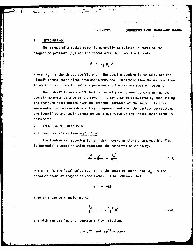
I INTRODUCTION
The thrust of a rocket motor is generally calculated in terms of the
stagnation pressure (po) and the throat area (A) from the formula
F = Cf Po A,
where Cf is the thrust coefficient. The usual procedure is to calculate the
"ideal" thrust coefficient from one-dimensional isentropic flow theory, and then
to apply corrections for ambient pressure and the various nozzle "losses".
The "ideal" thrust coefficient is normally calculated by considering the
overall momentum balance of the motor. It may also be calculated by considering
the pressure distribution over the internal surfaces of the motor. In this
memorandum the two methods are first compared, and then the various corrections
are identified and their effect on the final value of the thrust coefficient is
cons ide red.
2 IDEAL THRUST COEFFICIENT
2.1 One-dimensional isentropic flow
The fundamental equation for an ideal, one-dimensional, compressible flow
is Bernoulli's equation which describes the conservation of energy:
u2 +a2 a02- a 2 (2.1)
where u is the local velocity, a is the speed of sound, and a is the0
speed of sound at stagnation conditions. If we remember that
2a - yRT
then this can be transformed to
T o 0 1 2r- " 1 + y2(2.2)
and with the gas law and Isentropic flow relations
p -pRT and pp'Y - const
I

UNLIMITED
= I + 2 M (2.3)
and LP • 24
The mass-flow rate at any section Is constant:
th = pAu , p* A., u* (2.5)
where a * subscript denotes the throat conditions
The mass-flow rate can therefore be calculated by substituting (2.1) and (2.3)
in (2.5) to give
= 2- . (2.6)
Finally, we can use (2.5) to give relationship between Mach number and area ratio;
A1 + M (2.7)
2.2 Momentum balance equation
If we consider the overall momentum balance of the control volume shown
in Fig. i:
F - Ue+ pe A
L,

UNLIMITED
where u is the gas velocity at exit, p the static gas pressure and Aee e
the exit cross-sectional area. For the moment we shall assume that the ambient
pressure is zero.
From (2.1)
22 2
0
2Me (2.8)
[ 1 + .M2]
where Me denotes the Mach number at the exit plane.
Also, combining (2.4) and (2.7):
Pe Ae __ 2 (y -1"1M 29PoA e +T1 + (2.9)
so that, using (2.6), (2.8) and (2.9)
+1
0 2 { M e] + ]
or
M2 (1 + Y M 2 3Cfv " T y- 2 2. 0
2.3 Pressure integral method
While the method shown above provides a simple means of calculating the
ideal thrust coefficient, it leaves some ambiguities, particularly when we come
to consider how various "losses' In the thrust coefficient arise. Most
-7

UNLIMITED
immediately we observe that the final term (pe Ae) in the momentum equation
does not represent a force acting on the physical structure of the nozzle at
all, but is really an "adjustment" made to the equation because the control
volume has been drawn across the exit plane of the nozzle. The influence of
the nozzle will actually extend downstream of this point within an envelope
bounded by the Mach lines extending from the lip of the nozzle to the centre
line. In part this ambiguity arises because the "one-dimensional flow" assump-
tion cannot be true if the flow is to expand.
The alternative approach is to observe that the thrust is generated by the
integral of the internal pressure over the surface of the nozzle:
F 1pdA
where A is the axial cross-section of the flow. In fact the integration will
have to be made in two parts - one over the head-end of the motor, and the
second over the length of the nozzle. At this point we can also allow for the
finite contraction ratio of the nozzle
AfeF = P 0 Ao
+ pdA . (2.11)
0
If we differentiate the mass-flow equation (2.9) we have
dp + dA du . 0 (2.12)p A +
and since the differential forms of the gas law and isentropic flow equations
are
p P T
and
p p
-p 1 dTI T
B) " '

UNLIMITED
which, by differentiating (2.1) becomes
p u du . 2 duP a
Equation (2.12) can therefore be written as
dA (M 2 - 1) du (2.13)
which also indicates how the nozzle must change from a contraction to an
expansion as the Mach number passes unity to maintain a positive acceleration.
In fact we can use equation (2.1) to convert (2.13) entirely to terms of
Mach number:
dM _ du daM u a
and
2u du + 2 * a da 0
Y-1
dM"- du I + M 2 ]
and
dA 2 - 1 dM (2.14)A I~ + -1 M 21
which is the differential form of (2.7). We can now substitute this equation
together with (2.7) and (2.4) In (2.11):
~~~~~~+ PoM~) 7 v i+.2
F - po A 0- + dM
0

UNLIMITED
or
A " "Y+l 'Me
Cf A 0 + 2 2 = + Y M 3/2 dMf+ -A ,, 2.
The ratio A o/A, will be determined by the entry Mach number to the nozzle,
as in equation (2.7). When the entry Mach number is small, this term cancels
with the first term in the integral, as might be expected since Cf is not
very sensitive to entry Mach number. The integral then proves to be identical
with (2.10)
+12 1 ('+YMe)Me [1 + M2]
3 CORRECTION FOR AMBIENT PRESSURE
So far we have assumed that the ambient pressure is zero. In practice
with a finite ambient pressure (pa) we should continue the integral in
section 2.3 over the outside of the motor. The integral is simplified by the
fact that pa may be assumed everywhere constant. The thrust is then given by
T = Cf po A* + A pa dA
e
= Cf Po AA - Pa %
The integral here goes from the lip of the exit cone to the centre of the head
end of the motor. Thus
P - pa Aef f
10

UNLIMITED
If Pa is not constant over the outside of the motor, e.g. due to induced flow
past the motor, then it will be necessary to re-evaluate the integral to allow
for this effect.
4 THRUST COEFFICIENT LOSSES
4.1 General
There are a number of losses to the overall thrust which do not affect the
thrust coefficient, and we shall not consider those here. Under this category
we shall ignore effects which alter the flow area of the throat or the upstream
stagnation conditions. The major losses to thrust coefficient are then
- divergence losses
- skin friction losses
- two-phase flow losses
We must now consider how these losses are to be integrated into calculation of
the thrust coefficient.
4.2 Divergence losses
On exit from the nozzle the flow has a component of momentum in the radial
as well as the axial direction. Malina [ I] calculated the loss of thrust to
radial momentum by assuming that the exit flow formed a cone of streamlines
originated from a point source near the throat. He showed that the reduction
in axial momentum in this instance was by a factor
1 + cosand = 2
where e is the half angle of the cone. Nowadays more complete computer flow
predictions are available, but it appears that Malina's formula provides a high
degree of accuracy if the half-angle of the flow at exit is used.
Using Malina's formula one might assume that only the velocity terms in the
momentum balance equation would be affected. However, Landsbaum [ 2] pointed
out that the exit area involved in Malina's assumption is actually the cap of a
sphere and not the flat exit plane, and that the "one dimensional" calculation
of Cf is initially high, and using Malina's correction on all the terms in
Cfv provides a closer approximation to the actual correction, the errror then
being about 0.1% pessimistic for a 10:1 area ratio nozzle with 0 - 15°.
11 _

UNLIMITED
4.3 Skin friction loss
The drag force acting on a nozzle expansion cone can be calculated as:
Drag = f p u2 21 rdx
where r is the local radius of the nozzle, and cf is a skin friction
coefficient. The skin friction coefficient can be calculated by compressible
boundary layer methods which include the effects of the accelerating flow, but
as a first approximation
cf Re -2f = 0.0256 Rex
where Re is the Reynolds number based on distance down the flow. We canx
observe that cf decreases as we move further downstream.
If we observe that
2 P A,= pu • 7rr = -
C_,
cu f
Drag = A. _
Now u/c. is a component of the thrust coefficient momentum balance, and like
the thrust coefficient it increases only slowly as we go down the nozzle, with
a value of about 0.7 at the throat increasing to about 1.65 for a 12:1 area
ratio nozzle. The increase in u/c* is actually rather greater than the
decrease in skin friction coefficient, but it is probably close enough to write
Drag = f f dxPo A* C fe c, rd
where f is a non-dimensional factor accounting -for the variation of cf u/c.,
with x . We therefore see that if we define a skin friction loss efficiency
I f d~xrif Cfe r
12

UNLIMITED
it will apply only to the velocity term in the thrust coefficient. Typically
rIf is about 0.99.I 4.4 Two-phase flow losses
Most particularly in the case of aluminized composite propellants (where
up to 25% of the flow can be in the form of A]203 particles) the presence of
solid particles in the flow induce flow losses both by retaining energy which
should contribute to the thermodynamic expansion ("thermal lag") and by having
a lower acceleration than the gas ("velocity lag"). If a fraction C of the
exhaust is solid particles, the thrust is
Thrust = (1 - ) i ue + pe Ae + ni u
where up is the velocity of particles at the exit plane. If the velocity
lag is
T = (I- + ) ri u + p Ae e e
This simplified analysis suggests that the correction for two-phase flow
should only be applied to the velocity term. However, it is a simplified
analysis. If we examine in more detail what is happening within the nozzle
we find that the drag of the solid particles will slow the velocity of the gas
phase and increase its temperature, thereby reducing the Mach number of the gas.
The thermal lag of the particles will also tend to add heat to the flow down-
stream. Since in the expansion cone at least thrust is generated only by the
pressure of the gas, a reduction by Mach number represents a reduction in the
whole of Cfv
Part of the problem in assigning a correction for two-phase flow arises
from the problems of calculating the effect accurately. A large part of the
loss will occur upstream of the nozzle throat, and so will affect the character-
istic velocity c also. It is significant that where exact formulations of
two-phase flow problems have been carried out (e.g. Marble E 3] ) these have
concentrated on calculating the reduction in specific impulse, combining Cf
and c,.
5 CONCLUSIONS
This memo has shown that the value for the ideal, "one-dimensional" vacuum
thrust coefficient is the same when calculated by a momentum balance or by a

UNLIMITED
Spressure distribution method. Investigation of the various losses suggests
that the real thrust coefficient can be calculated from:
c it[,Cv+( Pe Ae-] Pa A eCf nd C + A, - Po A
where nd is the divergence loss efficiency
nt is the two-phase flow loss efficiency, and
nf is the skin-friction loss efficiency.
6 REFERENCES
No. Author Title, etc.
1 Malina, F. Characteristics of the Rocket Motor Unit based on
the Theory of Perfect Gases.
J. Franklin Inst., 230, p.433 (1940)
2 Landsbeum, E.M. Thrust of a Conical Nozzle.
ARS Journal, 29, p.2 12 (1959)
3 Marble, E. Nozzle Contours for Minimum Particle-Lag Loss.
AIAA Journal, 1, p.2793 (1963)
- '., L IC
CL14

UNLIMITED
Nomenclature
A conduit cross sectional area
A A cross sectional area at stagnation
A nozzle exit areaeA, throat area
a local speed of sound
a speed of sound at stagnation0
a* speed of sound at the throat
c, characteristic velocity
F thrust
ltotal mass flow rate
p pressure
PO stagnation pressure
exit plane pressure
Pa ambient pressure
R gas constant per unit mass
r local nozzle radius
T absolute temperature
T stagnation temperature
u local gas velocity
ue exit plane gas velocity
u4. throat gas velocity
Y ratio of specific heats
dimensionless velocity lag parameter
nd divergence loss efficiencyTnf skin friction loss efficiency
nt two-phase flow loss efficiency
Cdimensionless thermal lag parameter
p local gas density
PO stagnation gas density
p* gas density at throat
15

UNLIMITED
Non-dimensional numbers
Cf thrust coefficienct
Cfv thrust coefficient in vacuoCf skin friction coefficient
Cfe skin friction coefficient at exit plane
M Mach number
nozzle entry Mach number
Me Mach number at exit plane
R ex Reynolds number based on distance down the flow
16

'%emo. C
IHRUST4A
Fig. 1.
* ..:i..' classiflcation ;i '. I~~~.,- .~'te . ... .............. ........;)ossibl this sheet shou. , ,a :".t it . is ib aecessar:. tz, enter
.as.,.fi.4 .nformatioa. the box concerned a-or be nrkeao t nd.,,_i the .1assifcatino e (R).(C) U- (S)).
DLC Referenee (if known) 2. Originastor's Reference 3. Agency Reference 4. Report SecurityClaesification
Memorandum No. 150 1,Unclassified5. Orisinator's Code 6. Originator (Corporate Amthor) Wem end Location1 (if knoti)i, m)Propellants, Explosives and Rocket Motor Establishment,
Westcott, Aylesbury, Bucks.
Se.Sponsoring Agency's 6. Spensoring Agency (Costenct Authority) Em and LocationCode (if kown)
7. Title
ON THE CALCULATION OF THRUST COEFFICIENT
7a.Ticle is Foreign Leaguage (in the cese of treselatione)
7b. Pweoated at (for coafersee p ne). Title. plee end date of cemfeuses
S. Author .urname, initials ao Author 2 9b Authors 3, 4... 10. Date pp ref
Parkinson, R.C. Mace, S.A. 2.1981
11. Centract Pu3ber 12. Period 13. Project 14. Other Reference
15. Diteributim ottmout
beeriptore (of keyorde)
eotimm en ewf Oe ies e aper tf mecesseey
The thrust of a rocket motor is generally calculated from the stagnation,assure, the throat area, and a non-dimensional thrust coefficient dependent
upon the nozzle expansion area ratio. A comparison is made between momentumbalance and pressure Integral methods of calculating the ideal vacuum thrustcoefficient, and the results used to examine how corrections should be nade fornozzle divergence, skin friction and two-phase flow to obtain the real thrustcoefficient of the motor.

I A il. wY 1 1
I-