paroscientific, inc. digiquartz pressure...
TRANSCRIPT
Paroscientific, Inc.
Digiquartz® Pressure Instrumentation
User’s Manual for
Model 735 Intelligent Display And
Model 745 High Accuracy Laboratory Standard
“The standard by which other standards are measured”
TABLE OF CONTENTS Page #
1 INTRODUCTION ..............................................................1-1 1.1 Latest features....................................................................1-1 1.2 Conventions.......................................................................1-1 1.3 Warnings and Safety Precautions......................................1-2
2 GETTING FAMILIAR......................................................2-1 2.1 Physical Inspection............................................................2-1 2.2 Product Features and Configurations ................................2-1 2.3 Physical Description..........................................................2-2 2.4 Front Panel Features ..........................................................2-3 2.5 Rear Panel Features ...........................................................2-4
2.5.1 Model 735..................................................................2-4 2.5.2 Model 745..................................................................2-5
3 QUICK START ..................................................................3-1 3.1 Model 745..........................................................................3-1 3.2 Model 735..........................................................................3-1 3.3 Applying Pressure .............................................................3-5
4 USER INTERFACE...........................................................4-1 4.1 Front Panel.........................................................................4-1
4.1.1 Display.......................................................................4-1 4.1.2 Operating Modes .......................................................4-1 4.1.3 Keypad.......................................................................4-2 4.1.4 Configuration Menu Options.....................................4-3
4.1.4.1 Tare Menu ..........................................................4-3 4.1.4.2 Units Menu .........................................................4-4 4.1.4.3 Display Menu .....................................................4-4 4.1.4.4 Aux Menu...........................................................4-5
4.2 Rear Panel..........................................................................4-7 4.2.1 Power Options ...........................................................4-7 4.2.2 Terminal Block Descriptions.....................................4-8

4.3 Overpressure Alert.............................................................4-8
5 REMOTE OPERATION ...................................................5-1 5.1 Local vs. RS-232 Operation ..............................................5-1 5.2 Digiquartz® Software........................................................5-1
5.2.1 Digiquartz® Interactive 2.0 (DQI 2.0) ......................5-1 5.2.2 Digiquartz® Assistant (DQA) ...................................5-2 5.2.3 Digiquartz® Terminal (DQT) ...................................5-2
5.3 Command and Response Basics........................................5-3 5.4 Command and Response Format.......................................5-3 5.5 Establishing RS-232 Communications..............................5-5 5.6 Setting and Reading Parameter Values .............................5-7 5.7 Command Reference .........................................................5-8
5.7.1 Measurement Commands ..........................................5-8 5.7.1.1 Single Measurement Commands........................5-8 5.7.1.2 Sample and Hold Measurement Commands ......5-9 5.7.1.3 Continuous Measurement Commands..............5-11
5.7.2 Configuration Commands .......................................5-14 5.7.2.1 Enable Write Command ...................................5-14 5.7.2.2 Measurement Integration Time Commands .....5-14 5.7.2.3 Data Output Mode Command ..........................5-18 5.7.2.4 Engineering Units Commands..........................5-20 5.7.2.5 Tare and Overpressure Commands ..................5-21 5.7.2.6 Measurement Data Formatting Commands......5-24 5.7.2.7 Unit Identification Commands .........................5-28 5.7.2.8 Display Data Configuration Commands ..........5-30 5.7.2.9 Calibration Commands.....................................5-32 5.7.2.10 Diagnostic Commands......................................5-34 5.7.2.11 Global Commands ............................................5-35
5.8 High Speed Sampling ......................................................5-36 5.9 Networking ......................................................................5-36
5.9.1 Networking Basics...................................................5-37 5.9.2 RS-232 Loop Networking .......................................5-37
5.10 Displaying Data Remotely with Model 715 Display ......5-39

6 NANO-RESOLUTION FEATURES & FUNCTIONS ...6-1 6.1 Introduction .......................................................................6-1 6.2 Enabling Nano-Resolution ................................................6-2 6.3 Configuring IIR Filter Mode .............................................6-2 6.4 Configuring FIR Filter Mode ............................................6-4 6.5 Default Numeric Formats for IIR & FIR Modes...............6-6 6.6 Controlling the Numeric Format .......................................6-6
7 PRESSURE MEASUREMENT CONCEPTS .................7-1 7.1 Measurement Basics..........................................................7-1 7.2 Measurement Types...........................................................7-1 7.3 Sampling Types .................................................................7-3 7.4 Engineering Units ..............................................................7-4 7.5 Tare Function.....................................................................7-4 7.6 Resolution, Integration Time and Sampling Rate .............7-5
7.6.1 Definitions .................................................................7-5 7.6.2 Interdependencies ......................................................7-5
7.7 High Speed Sampling ........................................................7-9 7.8 Calculations and Formulas ................................................7-9
8 ACCESSORIES..................................................................8-1 8.1 Included Accessories .........................................................8-1 8.2 Optional Accessories .........................................................8-2
9 MAINTENANCE ...............................................................9-1
10 CALIBRATION ...............................................................10-1 10.1 Calibration Procedure......................................................10-1 10.2 Zero and Span Adjustments.............................................10-1 10.3 Calibrating Other Instruments .........................................10-3
11 WARRANTY ....................................................................11-1
12 SERVICE AND SUPPORT.............................................12-1
13 TROUBLESHOOTING...................................................13-1
14 “DISPLAY DATA INTERRUPTED” MESSAGE........14-1

15 PRESSURE UNIT CONVERSION TABLE..................15-1
16 GLOSSARY ......................................................................16-1
17 CONNECTOR DIAGRAMS...........................................17-1 17.1 Model 735/745 RS-232 Port Connector ..........................17-1 17.2 PC RS-232 Port Connector..............................................17-2 17.3 Model 735/745 DC-Power – I/O Terminal Block...........17-2 17.4 Model 735 Transducer Interface Terminal Block ...........17-3
18 WIRING DIAGRAMS.....................................................18-1 18.1 Connecting Digiquartz® Transducer to the Model 735 ..18-1 18.2 RS-232.............................................................................18-2 18.3 RS-232 Serial Loop Network ..........................................18-2 18.4 Model 715 Display ..........................................................18-4
19 HOW DO I …? .................................................................19-1
20 MENU TREE REFERENCE ..........................................20-1
21 COMMAND AND PARAMETER REFERENCE........21-1

1 Introduction Thank you for your purchase of a Digiquartz® Model 735 Intelligent Display or Model 745 Laboratory Standard. Please visit our website at www.paroscientific.com for the latest manual revision.
1.1 Latest features With firmware revision D1.06 or later, it is now possible to achieve parts-per-billion resolution (nano-resolution) as opposed to parts-per-million resolution in standard mode. This feature can be easily enabled/disabled via software commands. Please refer to Section 6 for additional information on this new feature.
1.2 Conventions The following conventions are used throughout this manual: Digiquartz® Intelligent Instrument – A Digiquartz® Model 735 Intelligent Display or Model 745 Laboratory Standard. Digiquartz® Intelligent Transmitter – Any Digiquartz® Series 1000, 6000, or 9000 Pressure Transmitter or Intelligent Depth Sensor. Digiquartz® Intelligent Device – Any Digiquartz® Intelligent Instrument or Transmitter. Digiquartz® Pressure Transducer – Any Digiquartz® pressure transducer with frequency outputs. CAUTION is used to draw your attention to a situation that may result in an undesirable outcome, but will not damage the unit. WARNING is used to draw your attention to a situation that may result in permanent damage to the unit or will void the warranty.
INTRODUCTION 1-1

INTRODUCTION 1-2
DANGER is used to draw your attention to a situation that may result in injury. Commands and parameters are shown in bold type. Example: PI and TI are commands that set the integration time in increments of 0.01 second.
1.3 Warnings and Safety Precautions Digiquartz® Intelligent Instruments are precision devices, and as such, they should be operated with a certain degree of care to ensure maximum performance. WARNING It is recommended that the input pressure not exceed the specified limit. Calibration can be affected if this limit is exceeded, and permanent damage can result if the unit is sufficiently overpressured. WARNING Excessive mechanical shock may cause irreparable damage. Do not drop a Digiquartz® Intelligent Instrument, or allow tools or other hard objects to fall on the unit or its pressure port.

2 Getting Familiar 2.1 Physical Inspection You should have received the following items with your Model 735/745 purchase:
• Model 735 or Model 745 • User’s manual • RS-232 serial cable • 110V or 220V AC adapter • 4 AA alkaline batteries • Model 735/745 Menu Quick Reference • Digiquartz® CD Library • Specification Control Drawing (SCD) for the Model 735 or 745 • Specification Control Drawing (SCD) for the Digiquartz®
pressure transducer (Model 735 only)
2.2 Product Features and Configurations Performance and feature specifications are subject to change. Please refer to the Specification Control Drawing (SCD) that was delivered with your unit.
PERFORMANCE (MODEL 745) Resolution: Better than 0.0001% full scale Accuracy: Better than 0.008% full scale accuracy for all ranges,
except 0.08 hPa for barometric range (Model 745-16B)
0.02% full scale for 30,000 and 40,000 psi units
PERFORMANCE (MODEL 735) Per external transducer Specification Control Drawing (SCD).
GETTING FAMILIAR 2-1

RANGES Model 745
• 19 absolute pressure ranges: 0-15 psia (0.1 MPa) to 0-40,000 psia (276 MPa) • 6 gauge pressure ranges:
0-15 psig (0.1 MPa) to 0-200 psig (1.38 MPa) Model 735
• Supports all Paroscientific frequency output pressure sensors with temperature signal outputs
FEATURES • Intuitive front panel menu system • Two-line display with menu-selectable functions:
• Taring • Engineering units • Pressure bar graph • Sensor temperature • Password protection • Rate of pressure change • Resolution and sampling speed • Adjustable number of display digits • User choice of stored or external text
• Optional part per billion resolution (Nano-resolution) • Rack or panel mount capability • Enhanced RS-232 command set • 110V or 220V AC adapter power • Multiple remote display capability • Free configuration and logging software • 20 hours battery operation in standard resolution mode (4 AA size
alkaline)
QUALITY AND STANDARDS • CE marked. • NIST traceable.
2.3 Physical Description The Model 735 and 745 are nearly identical in function and appearance. The main difference is that the Model 735 is used with an external
GETTING FAMILIAR 2-2
Digiquartz® pressure transducer, while the Model 745 has an internal Digiquartz® pressure transducer. The Model 735/745 display pressure measurement values and related information. They can be used as stand-alone instruments or as part of an RS-232 based data acquisition system. The units can be configured using either the front panel user interface or via the RS-232 serial port. The front panel user interface provides convenient access to the most often used configuration functions. Other configuration functions are accessed via the RS-232 serial port.
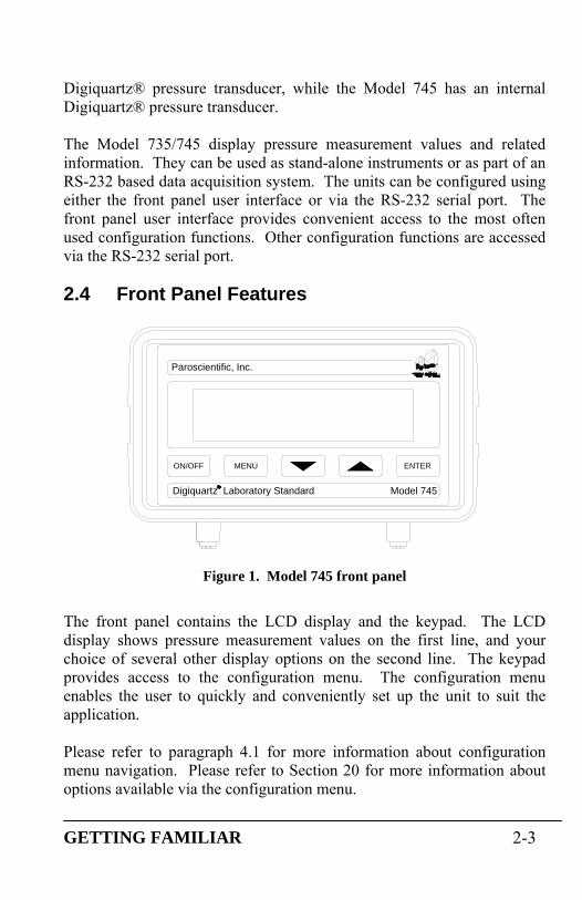
2.4 Front Panel Features
Digiquartz Laboratory Standard
ON/OFF
Paroscientific, Inc.
Model 745
ENTERMENU
R
Figure 1. Model 745 front panel
The front panel contains the LCD display and the keypad. The LCD display shows pressure measurement values on the first line, and your choice of several other display options on the second line. The keypad provides access to the configuration menu. The configuration menu enables the user to quickly and conveniently set up the unit to suit the application. Please refer to paragraph 4.1 for more information about configuration menu navigation. Please refer to Section 20 for more information about options available via the configuration menu.
GETTING FAMILIAR 2-3

2.5 Rear Panel Features
2.5.1 Model 735
Figure 2. Model 735 rear panel
The Model 735 rear panel contains the following features:
• AC adapter jack • Power and I/O terminal block • RS-232 port • Battery compartment • Transducer terminal block • Chassis grounding lug
Please refer to paragraph 4.2 for detailed information about the Model 735 rear panel features.
GETTING FAMILIAR 2-4

2.5.2 Model 745
Figure 3. Model 745 rear panel
The Model 745 rear panel contains the following features:
• Pressure port(s) • AC adapter jack • Power and I/O terminal block • RS-232 port • Battery compartment • Chassis grounding lug
Please refer to paragraph 4.2 for detailed information about the Model 745 rear panel features.
GETTING FAMILIAR 2-5

3 Quick Start This section will help you to quickly set up the Model 735/745 and begin taking pressure measurements.
3.1 Model 745 Step 1: Apply power to the Model 745 Refer to paragraph 4.2.1 for detailed information.
Step 2: Turn Model 745 on Press the ON/OFF key to turn on the Model 745. After a short initialization, the Model 745 will begin to display pressure measurement values. Your Model 745 should now be displaying correct pressure measurement values. If the displayed values are not correct, refer to Section 13 for troubleshooting tips. Refer to Section 4 for information about configuring your Model 745 according to your application.
3.2 Model 735 Step 1: Connect an external Digiquartz® pressure
transducer to the Model 735 • Refer to paragraph 18.1 for detailed information.
Step 2: Apply power to the Model 735 • Refer to paragraph 4.2.1 for detailed information.
Step 3: Turn Model 735 on • Press the ON/OFF key to turn on the Model 735. After a
short initialization, the Model 735 will begin to display pressure measurement values.
Note: If the Model 735 has not yet been configured with the calibration coefficients of the particular Digiquartz® pressure transducer to which it is connected, incorrect pressure measurement values will be displayed and the overpressure alarm may sound.
QUICK START 3-1

Step 4: Establish communications between the Model 735 and a PC
• Install Digiquartz® Interactive 2.0 on your PC. Digiquartz® Interactive 2.0 can be installed from the Digiquartz® CD Library that was included with your Model 735 or downloaded at the Paroscientific web site at www.paroscientific.com.
• Connect the RS-232 port of your Model 735 to the RS-232 port of your PC, and power up the instrument.
• Run Digiquartz® Interactive 2.0.
• Select the Digiquartz® Terminal option, and click Next.
• You send commands to the unit by typing them into the Command field. Responses to commands will be displayed in the Response window.
If you are unable to establish communications, refer to the DQI online help information and Section 13 of this manual.
Step 5: Configure the Model 735 with the Digiquartz® pressure transducer coefficients and parameters
Please refer to Section 5 for more information about configuration commands and their use.
• Set the overpressure alarm setpoint
The overpressure alarm setpoint (OP) is set to 0.0 psi at the factory. OP is set in the current pressure units. We recommend that the pressure units be set to psi (UN=1) prior to setting OP; refer to paragraphs 5.7.2.4 for details about setting pressure units. OP should be set to the full-scale pressure indicated on the Digiquartz® transducer. The following example assumes a 45 psi transducer: Typical set command: *0100EW*0100OP=45 Typical set response: *0001OP=45.00000
QUICK START 3-2

• Set the transducer coefficient values
The following parameters must be set to the corresponding values on the Calibration Coefficients data sheet that was delivered with your Digiquartz® transducer: U0, Y1, Y2, Y3, C1, C2, C3, D1, D2, T1, T2, T3, T4, and T5. You must set all calibration parameters to the exact values listed on the Calibration Coefficients data sheet. CAUTION Setting calibration coefficients to incorrect values will result in incorrect pressure measurement values. The following example shows how to set the U0 coefficient to a typical value. Other coefficients are set in a similar manner. Refer to paragraph 5.7.2.9 for more information. Typical set command: *0100EW*0100U0=5.860513 Typical set response: *0001U0=5.860513
• Set the transducer model number MN should be set to the model number indicated on the Digiquartz® pressure transducer. The following example assumes a model 245A transducer. Typical set command: *0100EZ*0100MN=245A Typical set response: *0001MN= 245A
• Set the transducer full-scale pressure value Set PF to the full-scale pressure value indicated on the Digiquartz® pressure transducer. PF is set in the current pressure units. We recommend that the pressure units be set to psi (UN=1) prior to setting PF. Refer to paragraph 5.7.2.4 for more information about setting pressure units.
QUICK START 3-3

CAUTION PF must be set to the full-scale pressure value of the Digiquartz® transducer. Failure to do so will result in improper formatting of pressure measurement values. The example below is for a 45 psi transducer. Typical set command: *0100EZ*0100PF=45 Typical set response: *0001PF=45.00000
• Set the transducer overpressure limit value PL is typically set to 1.2 times the full-scale pressure value of the Digiquartz® transducer. Refer to the transducer Specification Control Drawing for specific overpressure limits. PL is always set and reported in psi, regardless of the pressure unit setting. The example shown below is for a 45 psi transducer (45 x 1.2 = 54). Typical set command: *0100EZ*0100PL=54 Typical set response: *0001PL=54.00000
• Set the transducer type value Set PO according to the Digiquartz® pressure transducer type (absolute, gauge, or differential). The table below shows the integer values used with PO to identify the transducer type:
QUICK START 3-4

PO value Transducer type
0 Absolute 1 Gauge 2 Differential
The following example assumes an absolute transducer: Typical set command: *0100EZ*0100PO=0 Typical set response: *0001PO=0
• Set the transducer serial number value Set SN to the serial number indicated on the Digiquartz® transducer. The following example assumes serial number 1234567:
Typical set command: *0100EZ*0100SN=1234567 Typical set response: *0001SN=1234567
At this point, your Model 735 should be fully configured and should be displaying correct pressure measurement values. If the displayed values are not correct, refer to Section 13 for troubleshooting tips. Refer to Section 4 for information about configuring your Model 735 according to your application.
3.3 Applying Pressure Now that you have your Model 735/745 up and running, you are ready to connect your pressure source to the pressure port. If you are using a Model 745, you will connect your pressure source to the pressure port(s) located on its rear panel. If you are using a Model 735, your pressure source will be connected directly to the pressure port of the external Digiquartz® pressure transducer.
ABSOLUTE UNITS Units equipped with absolute pressure transducers have a single pressure port.
QUICK START 3-5

QUICK START 3-6
GAUGE UNITS Units equipped with gauge pressure transducers have two pressure ports. Pressure should only be applied to the positive pressure port. The negative pressure port must remain vented to atmospheric pressure. WARNING Consult the Model 745 or Digiquartz® pressure transducer SCD for proper pressure fitting tightening torque. Do not apply excessive torque or permanent damage to the pressure fitting may result. WARNING When connecting pressure fittings, always use a second wrench to stabilize the pressure fitting on the Model 745 or Digiquartz® pressure transducer, or permanent damage to the Model 745 or Digiquartz® pressure transducer may result. WARNING All Digiquartz® pressure transducer are designed to operate over a specific pressure range. Do not overpressure the Model 745 or Digiquartz® pressure transducer, or permanent damage may result. CAUTION Transducers that are intended to be used in liquid pressure applications are oil-filled at Paroscientific. If your Model 745 or Digiquartz® pressure transducer is oil-filled, do not pull a vacuum or pressurize with gas, or gas bubbles may be introduced into the pressure transducer, which will negatively affect its performance. Pressure lines connected to oil-filled transducers should be filled with clean hydraulic fluid and bled to remove gas bubbles. Consult the Model 745 or Digiquartz® pressure transducer SCD to determine the oil used to fill the transducer. CAUTION Pressure head effects result in zero offsets. These effects are more pronounced when liquid-filled pressure lines are being used. These effects can be minimized by keeping the transducer pressure port and the pressure source at the same elevation, or by using the tare or pressure adder functions to make an offset correction to compensate for the pressure head.

4 User Interface 4.1 Front Panel
4.1.1 Display The Model 735/745 features a 2-line, 16 character alphanumeric LCD display.
4.1.2 Operating Modes The Model 735/745 operates in one of two modes: Pressure Display Mode or Configuration Menu Mode.
PRESSURE DISPLAY MODE At power-up, the Model 735/745 will be in Pressure Display Mode. When in Pressure Display Mode, the first line displays the following information:
• Pressure value • Pressure unit • Tare indicator • Pressure value update indicator (blinking dot between the
pressure value and pressure unit) The second line can display one of the following:
• Pressure bar graph • Digiquartz® pressure transducer internal temperature • Pressure rate of change • Text stored within the Model 735/745 • External text sent to the Model 735/745 via the RS-232 port • No information
The second line can also display an overpressure warning if the measured pressure exceeds the limits of the Digiquartz® pressure transducer. This feature is not available in the pressure rate of change and external text display modes.
USER INTERFACE 4-1
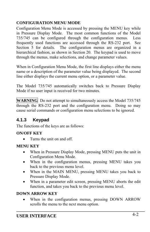
CONFIGURATION MENU MODE Configuration Menu Mode is accessed by pressing the MENU key while in Pressure Display Mode. The most common functions of the Model 735/745 can be configured through the configuration menus. Less frequently used functions are accessed through the RS-232 port. See Section 5 for details. The configuration menus are organized in a hierarchical fashion, as shown in Section 20. The keypad is used to move through the menus, make selections, and change parameter values. When in Configuration Menu Mode, the first line displays either the menu name or a description of the parameter value being displayed. The second line either displays the current menu option, or a parameter value. The Model 735/745 automatically switches back to Pressure Display Mode if no user input is received for two minutes. WARNING Do not attempt to simultaneously access the Model 735/745 through the RS-232 port and the configuration menu. Doing so may cause serial commands or configuration menu selections to be ignored.
4.1.3 Keypad The functions of the keys are as follows:
ON/OFF KEY • Turns the unit on and off.
MENU KEY • When in Pressure Display Mode, pressing MENU puts the unit in
Configuration Menu Mode. • When in the configuration menus, pressing MENU takes you
back to the previous menu level. • When in the MAIN MENU, pressing MENU takes you back to
Pressure Display Mode. • When in a parameter edit screen, pressing MENU aborts the edit
function, and takes you back to the previous menu level.
DOWN ARROW KEY • When in the configuration menus, pressing DOWN ARROW
scrolls the menu to the next menu option.
USER INTERFACE 4-2

• When in a parameter entry screen, DOWN ARROW decrements the data value.
UP ARROW KEY • When in a menu, pressing UP ARROW scrolls the menu to the
previous menu option. • When in a parameter entry screen, UP ARROW increments the
data value.
ENTER KEY • When in the configuration menus, pressing ENTER selects the
displayed menu item. • When in a parameter entry screen, ENTER accepts the displayed
parameter value.
4.1.4 Configuration Menu Options The Configuration Menu allows you to configure the Model 735/745 according to your application. Refer to the Menu Quick Reference card or the menu tree in Section 20.
4.1.4.1 Tare Menu CURRENT VALUE Displays the current tare value. This is the value that is subtracted from pressure measurements when tare is on.
TARE Turns tare on. When tare is on, the current tare value is subtracted from pressure measurements. When Tare is selected, the pressure at that time becomes the current tare value. If tare is already on when this option is selected, tare remains on, and the pressure at that time becomes the new current tare value. When tare is on, a “T” is displayed to the left of the pressure value to indicate that it is a tared pressure value.
TARE OFF Turns tare off. When tare is off, the actual measured pressure value is displayed.
USER INTERFACE 4-3

4.1.4.2 Units Menu PRESSURE UNITS Selects the pressure unit. The following options are available:
• psi • hPa • bar • kPa • MPa • inHg • mmHg • mH2O • User-defined pressure unit
The user-defined pressure unit can be selected via the configuration menu, but must be configured via RS-232. Refer to Section 5 for details.
TEMP. UNITS Selects the internal sensor temperature unit. The following options are available:
• °C • °F
4.1.4.3 Display Menu DECIMAL DIGITS Selects the number of significant digits used to display pressure measurement values. Fewer significant digits will be displayed if the pressure resolution and/or pressure unit will not provide the specified number of significant digits. When the number of digits is set to 6, the maximum number of significant digits is always displayed.
LINE 2 DISPLAY Selects the information to be displayed on the second line. The following options are available:
• Bar graph – gives a graphic representation of the current pressure value as a percentage of full-scale pressure.
• Sensor Temp. – displays the Digiquartz® pressure transducer internal temperature.
USER INTERFACE 4-4

• Pressure Rate – displays the pressure rate of change in the current pressure unit per second. Pressure rate is calculated as the difference between adjacent pressure measurements divided by the measurement time interval. Time interval accuracy is ±10 milliseconds.
• Stored Text – displays the text stored within the Model 735/745. The text is defined via the RS-232 port using the UL parameter. Refer to paragraph 5.7.2.8 for more information.
• External Text – displays the text sent via the RS-232 port using the DT command. The text is not stored within the Model 735/745, and will be lost if the unit is turned off.
• No Line 2 – No information is displayed on the second line. The second line can also display an overpressure warning if the measured pressure exceeds the limits of the Digiquartz® pressure transducer. The overpressure warning is not available when the external text display option has been selected. Depending on the second line display option, the overpressure warning is either “OVERPRESSURE!” or “OVPR”.
4.1.4.4 Aux Menu SAMPLING TIME Selects the measurement sampling time. The range is .002 to 131.07 seconds in .002-second increments.
UNIT ID Selects the unit ID for networking applications. The range is 01 to 98.
PASSWORD Selects the password required to change settings within the Configuration Menu. The password is a four-digit integer value. When the password value is 0000, the password function is disabled, and no password is required to change settings. When the password value is non-zero, the password will be requested each time a setting is to be changed. If the proper password is entered, the setting can be changed; if not, you will be returned to the menu. Contact Paroscientific if you are unable to configure your Model 735/745 due to a lost password.
USER INTERFACE 4-5

VERSION Displays the firmware versions. This information may be helpful for diagnostic purposes.
BAUD RATE Selects the RS-232 baud rate. The following options are available:
• 19200 • 9600 • 4800 • 2400 • 1200 • 600 • 300
USER INTERFACE 4-6

4.2 Rear Panel
4.2.1 Power Options The Model 735/745 provides three power options.
AC ADAPTER A 120VAC or 230VAC AC adapter was supplied with the Model 735/745. It plugs into the power jack located in the lower left corner of the rear panel.
BATTERIES The Model 735/745 can be powered by four AA alkaline batteries. A set of batteries was supplied with the unit. The battery compartment is located on the rear panel. Open the battery compartment by inserting a tool into the small opening at the top of the battery compartment cover and pressing downward while pulling the cover outward. Batteries must be installed per the diagram inside the battery compartment. The Model 735/745 runs for more than 20 hours on a fresh set of premium AA alkaline batteries. The battery level is monitored, and “LOW BATTERY” is displayed on the second line when the batteries are nearly discharged. A few hours of operation remain at the time that the “LOW BATTERY” indication is first displayed. WARNING Use only AA alkaline batteries. Other types, including rechargeable batteries, are not recommended. WARNING Do not allow batteries to remain in the Model 735/745 for an extended period of time. Discharged batteries can become leaky over time, and could cause significant damage to the unit. It is recommended that batteries be examined periodically for leakage, and that any suspect batteries be removed. If the unit will not be used for an extended period of time, it is recommended that the batteries be removed.
WIRE INTERFACE The DC Power – I/O terminal block provides a means of wiring DC power to the Model 735/745.
USER INTERFACE 4-7

USER INTERFACE 4-8
4.2.2 Terminal Block Descriptions Terminal block(s) are provided for making wire connections to the Model 735/745. The terminal blocks can be unplugged from the unit to simplify wiring. Refer to the pinout diagrams on the rear panel label when making connections.
DC POWER – I/O TERMINAL BLOCK The DC Power – I/O terminal block provides the following connections:
• DC power and power ground • Model 715 remote display signals • Overpressure output
Refer to paragraph 17.3 for detailed information regarding the DC Power – I/O terminal block. Refer to paragraph 5.7.2.5 for detailed information regarding the overpressure output.
TRANSDUCER INTERFACE TERMINAL BLOCK (MODEL 735 ONLY) The transducer interface terminal block provides the connections to the external Digiquartz® pressure transducer. Refer to paragraph 18.1 for detailed information regarding the transducer interface terminal block
4.3 Overpressure Alert The overpressure alert is an audible alarm that works in conjunction with the overpressure output. It sounds whenever the displayed pressure exceeds a user-selectable pressure setpoint. The setpoint is controlled via RS-232 by the OP parameter. Refer to paragraph 5.7.2.5 for detailed information regarding the overpressure function and the OP parameter.

5 Remote Operation 5.1 Local vs. RS-232 Operation The Model 735/745 can be operated either as a stand-alone unit, or as part of a computer-based data acquisition system via its RS-232 communications port. Virtually all of the functionality of the Model 735/745 is available via the RS-232 port. Some of the unit’s more specialized features can only be configured via the RS-232 port. No special configuration is required to access the Model 735/745 via the RS-232 port. Simply connect its industry-standard RS-232 port to the RS-232 port of your host device, set your host device to the proper baud rate and serial protocol, and you are ready to communicate with the Model 735/745. The Model 735/745 RS-232 port is directly compatible with that of the PC. Any standard male to female 9-pin serial cable can be used to make the necessary connections. A serial cable (Paroscientific PN 6409-003) is supplied with your Model 735/745. WARNING Do not attempt to simultaneously access the Model 735/745 through the RS-232 port and the configuration menu. Doing so may cause serial commands or configuration menu selections to be ignored.
5.2 Digiquartz® Software Paroscientific provides several software programs that simplify common measurement and configuration tasks. These programs can be found on the Digiquartz® CD Library, which is provided with the Model 735/745. The latest versions of these and other software programs are also available at the Paroscientific web site, at www.paroscientific.com.
5.2.1 Digiquartz® Interactive 2.0 (DQI 2.0) Digiquartz ® Interactive 2.0 is a Windows program that makes it easy to communicate with and configure DIGIQUARTZ® Intelligent devices. We encourage you to install DQI 2.0 and use it to verify proper device
REMOTE OPERATION 5-1

operation, configure your device, take measurements, and experiment with its functions. DQI 2.0 is separated into two main sections: Configuration and Monitoring, and Digiquartz® Terminal. The Configuration and Monitoring section provides a means of viewing, changing, storing, and retrieving the configuration parameters of your instrument. It also allows you to take measurements and display them numerically and in a real-time graph. Measurement data may also be logged to a text file in a format that can be easily imported into popular PC programs such as Microsoft Excel® or Word®. The Digiquartz® Terminal section allows you to interactively communicate with your instrument using text-based commands. Measurement data may be logged to a text file in a format that can be easily imported into popular PC programs such as Microsoft Excel® or Word®.
5.2.2 Digiquartz® Assistant (DQA) Digiquartz® Assistant is a Windows data logging program. With DQA, you can log time-stamped measurement data from up to 8 Digiquartz® intelligent devices. Measurement data can also be displayed in real time in an automatically scaled graph. Data is stored to a text file in a format that can easily be imported into popular PC programs such as Microsoft Word or Excel. Refer to the help function in DQA for more information.
5.2.3 Digiquartz® Terminal (DQT) Digiquartz® Terminal is a Windows terminal program that was developed specifically for use with Digiquartz® intelligent devices. Like traditional terminal programs, Digiquartz® Terminal lets you interactively communicate with intelligent devices. In addition, Digiquartz® Terminal can log time-stamped measurement data to a text file in a format that can easily be imported into popular PC programs such as Microsoft Word or Excel. Refer to the help function in Digiquartz® Terminal for more information.
REMOTE OPERATION 5-2

5.3 Command and Response Basics The Model 735/745 is remotely controlled by serial ASCII command strings. The following basic tasks can be accomplished by sending the appropriate command:
• Take a measurement • Perform a control function, such as locking the baud rate • Set an operating parameter, such as integration time • Read the value of an operating parameter
When setting virtually all parameter values, you must precede the command with an EW command. This prevents accidental alteration of stored parameter values. Please refer to paragraphs 5.6 and 5.7.2.1 for more information about the EW command. Measurement commands typically generate a response that contains the measurement data. Parameter-set commands typically generate a response that reports the updated parameter value. Parameter-read commands report the current parameter value. When a command is received, any command that is in progress will be aborted. This enables you to send an RS-232 command to the Model 735/745 at any time, regardless of its current activity.
5.4 Command and Response Format In general, RS-232 commands and responses are made up of the following:
START CHARACTER • The start character is an asterisk (ASCII 42).
DESTINATION ID • The destination ID identifies the device that is to receive the
command or response. • The destination ID is a two-digit integer between 00 and 99. ID
00 is reserved for the serial host, usually a PC.
SOURCE ID • The source ID identifies the device that is sending the command
or the response.
REMOTE OPERATION 5-3

• The source ID is a two-digit integer between 00 and 98. ID 00 is reserved for the serial host, usually a PC.
COMMAND OR RESPONSE DATA • A wide variety of commands and resulting response data are
available. Refer to paragraph 5.7 for detailed information.
TERMINATION CHARACTERS • The termination characters are carriage return (ASCII 13) and
linefeed (ASCII 10).
COMMAND FORMAT Commands are typically sent in the following format: *0100P3CrLf Where: * = Start character Asterisk, ASCII 42
01 = Destination ID ID of the Model 735/745 that is to receive the command.
00 = Source ID ID of the device that is sending the command (Serial host is ID 00)
P3 = Command P3 is an example. Refer to paragraph 5.7 for descriptions of the entire command set.
Cr = Carriage return ASCII 13 Lf = Linefeed character ASCII 10
RESPONSE FORMAT Responses are typically received in the following format: *000114.4567CrLf
REMOTE OPERATION 5-4

Where: * = Start character Asterisk, ASCII 42 00 = Destination ID ID of the serial host that is to receive
the response. 01 = Source ID ID of Model 735/745 that is
responding 14.4567 = Data Data sent in response to the prior
command) Cr = Carriage return ASCII 13 Lf = Linefeed character ASCII 10 These examples are typical. Refer to paragraph 5.7 for specific details regarding each available command.
5.5 Establishing RS-232 Communications The following are two methods of establishing and verifying RS-232 communications between the Model 735/745 and a PC.
USING DIGIQUARTZ® INTERACTIVE 2.0 SOFTWARE The easiest way to establish RS-232 communications is by using Digiquartz® Interactive 2.0 (DQI 2.0) software. Step 1. Connect the Model 735/745 to the PC: Connect the Model 735/745 RS-232 port to the PC RS-232 port using the serial cable (Paroscientific PN 6409-003) that was provided with the unit. Any other standard RS-232 serial cable intended for use with the PC can also be used. Step 2. Install DQI 2.0: Insert the Digiquartz® CD Library CD into your CDROM drive, and follow the installation instructions. Step 3. Run DQI 2.0: Power up the Model 735/745, and run DQI 2.0. At the Startup screen, select the PC com port number that you are using, and click the Detect button. DQI 2.0 will search for the unit, and establish communications with it automatically. Click the OK button to exit the Startup screen and enter DQI 2.0. At this point, DQI 2.0 should be able to communicate with the unit. Refer to the DQI 2.0 help feature for more information about using DQI 2.0.
REMOTE OPERATION 5-5

USING A TERMINAL PROGRAM A standard terminal program can also be used to establish RS-232 communications with the Model 735/745. Digiquartz® Terminal (DQT) software can be used for this purpose. DQT is provided on the Digiquartz® CD Library CD. Step 1. Connect the Model 735/745 to the PC: Connect the Model 735/745 RS-232 port to the PC RS-232 port using the serial cable (Paroscientific PN 6409-003) that was provided with your unit. Any other standard RS-232 serial cable intended for use with the PC can also be used. Step 2. Install DQT: Insert the Digiquartz® CD Library CD into your CDROM drive, and follow the installation instructions. Any other terminal program already installed on your PC can also usually be used. Step 3. Determine the current baud rate and ID settings of your Model 735/745: Power up your unit, and press the MENU key to enter Configuration Menu mode. From the MAIN MENU, scroll to Aux Menu and select it using the Enter key. Scroll the AUX MENU to Unit ID, and select it using the Enter key. Note the unit ID. Press the MENU key to return to the AUX MENU. Scroll the AUX MENU to Baud Rate, and select it using the Enter key. Note the baud rate; you may change the baud rate using the UP ARROW and DOWN ARROW keys. Press the ENTER key to return to Pressure Display mode. Step 4. Configure the terminal program: Set the com port to the PC com port number that you are using. Set the baud rate to match the Model 735/745. Set the communications protocol to 8 data bits, no parity, and 1 stop bit. If DQT is not being used, it is often necessary to configure the terminal program to append a line feed character to each carriage return character. At this point, the terminal program should be able to communicate with the unit. Refer to paragraph 5.7 for detailed command and response information. Refer to the DQT reference feature for detailed information about using DQT.
REMOTE OPERATION 5-6
5.6 Setting and Reading Parameter Values The behavior of the Model 735/745 is controlled by several operating parameters. The values of these parameters are stored in non-volatile memory. Commands are provided to set and read the parameters values. Refer to paragraph 5.7.2 for detailed information about the various parameters.
SETTING PARAMETER VALUES Each parameter-set command must be preceded with the EW enable write command. The purpose of this is to reduce the chance of changing a parameter value by mistake. Parameter set commands will be ignored unless they are preceded with an EW command. See paragraph 5.7.2.1 for more information about the EW command. The following is an example of a parameter-set command preceded with the EW (enable write) command. For this example, the UN (pressure unit) parameter will be set to a value of 1. Command: *0100EW*0100UN=1CrLf Response: *0001UN=1CrLf All other writable parameters are set in the same way. Some parameters are read-only, and cannot be set.
READING PARAMETER VALUES All parameters can be read without preceding the command with an EW (enable write) command. The following is an example of a parameter-read command. For this example, the UN (pressure unit) parameter will be read. Command: *0100UNCrLf Response: *0001UN=1CrLf CAUTION Repeatedly setting or reading parameter values may temporarily prevent the display from being updated.
REMOTE OPERATION 5-7

5.7 Command Reference
5.7.1 Measurement Commands The following commands are used to initiate measurements, and to control measurement integration time. For additional commands associated with Nano-Resolution, please refer to Section 6.
5.7.1.1 Single Measurement Commands The following commands are used to initiate single measurements. They return the resulting measurement value as soon as it is available. P1 Sample and send one pressure period measurement in units of
microseconds. Action: Measure pressure period, send pressure period value, and
await next command. Typical command: *0100P1 Typical response: *000128.123456 (Value: 28.123456) Note: Repeatedly issuing the P1 command will temporarily prevent the front panel display from being updated.
P3 Sample and send one pressure measurement in selected
engineering units. Action: Measure temperature period, measure pressure period,
calculate temperature-compensated pressure, send pressure value, and await next command.
Typical command: *0100P3 Typical response: *000114.71234 (Value: 14.71234)
REMOTE OPERATION 5-8

Q1 Sample and send one temperature period measurement in units of microseconds. Action: Measure temperature period, send temperature period
value, and await next command. Typical command: *0100Q1 Typical response: *00015.1234567 (Value: 5.1234567)
Note: Repeatedly issuing the Q1 command will temporarily prevent the front panel display from being updated.
Q3 Sample and send one temperature measurement in selected
engineering units. Action: Measure temperature period, calculate temperature, send
temperature value, and await next command. Typical command: *0100Q3 Typical response: *000122.345 (Value: 22.345)
Note: Repeatedly issuing the Q3 command will temporarily prevent the front panel display from being updated.
5.7.1.2 Sample and Hold Measurement Commands The following commands are used to initiate and send single sample and hold measurements. Measurement values are held until the next command is received. If the next command is a DB command, the measurement value is sent; if it is any other command, the measurement value is lost. If a DB command is received before the measurement command is complete, the measurement value will be sent as soon as it is available. CAUTION Sample and hold commands will temporarily prevent the front panel display from being updated until the DB command is received or the sample and hold command is cancelled by the next valid command.
REMOTE OPERATION 5-9

P5 Sample and hold one pressure measurement in selected engineering units. Action: Measure temperature period, measure pressure period,
calculate temperature-compensated pressure, save pressure value, and await DB command.
Typical command: *0100P5 Typical response: No response until DB command is received
P6 Sample and hold one pressure period measurement in units of
microseconds. Action: Measure pressure period, save pressure period value, and
await DB command. Typical command: *0100P6 Typical response: No response until DB command is received
Q5 Sample and hold one temperature measurement in selected
engineering units. Action: Measure temperature period, calculate temperature, save
temperature value, and await DB command. Typical command: *0100Q5 Typical response: No response until DB command is received
Q6 Sample and hold one temperature period measurement in units of
microseconds. Action: Measure temperature period, save temperature period
value, and await DB command. Typical command: *0100Q6 Typical response: No response until DB command is received
DB Dump Buffer. Send a held measurement value.
Action: If a measurement value is being held, send it, otherwise do nothing.
Typical command: *0100DB Typical response: *000114.12345 (Value: 14.12345)
REMOTE OPERATION 5-10

5.7.1.3 Continuous Measurement Commands The following commands are used to initiate and control continuous measurements. Continuous measurement commands repeatedly take measurement samples and return measurement values until commanded to stop. Continuous measurements are cancelled by sending any valid command. P2 Continuously sample and send pressure period measurement
values in units of microseconds. Action: Measure pressure period, send pressure period value, and
repeat until commanded to stop. Typical command: *0100P2 Typical response: *000128.123456 (Value: 28.123456) *000128.123457 (Value: 28.123457) *000128.123456 … (Value: 28.123456)
Note: The P2 command will temporarily prevent the front panel display from being updated.
P4 Continuously sample and send pressure measurement values in selected engineering units. Action: Measure temperature period, measure pressure period,
calculate temperature-compensated pressure, send pressure value, and repeat until commanded to stop.
Typical command: *0100P4 Typical response: *000114.71234 (Value: 14.71234) *000114.71235 (Value: 14.71235) *000114.71234 … (Value: 14.71234)
REMOTE OPERATION 5-11
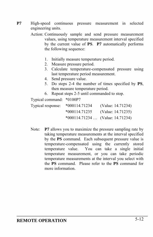
P7 High-speed continuous pressure measurement in selected engineering units. Action: Continuously sample and send pressure measurement
values, using temperature measurement interval specified by the current value of PS. P7 automatically performs the following sequence:
1. Initially measure temperature period. 2. Measure pressure period. 3. Calculate temperature-compensated pressure using
last temperature period measurement. 4. Send pressure value. 5. Do steps 2-4 the number of times specified by PS,
then measure temperature period. 6. Repeat steps 2-5 until commanded to stop.
Typical command: *0100P7 Typical response: *000114.71234 (Value: 14.71234) *000114.71235 (Value: 14.71235) *000114.71234 … (Value: 14.71234)
Note: P7 allows you to maximize the pressure sampling rate by
taking temperature measurements at the interval specified by the PS command. Each subsequent pressure value is temperature-compensated using the currently stored temperature value. You can take a single initial temperature measurement, or you can take periodic temperature measurements at the interval you select with the PS command. Please refer to the PS command for more information.
REMOTE OPERATION 5-12

PS Set or read the temperature measurement interval used by the P7 command. Action: Controls how often temperature measurements are taken
during a P7 pressure measurement sequence. If PS=0, an initial temperature measurement is taken, and
all subsequent pressure measurements are compensated using that value.
If PS=1, a temperature measurement is taken before each pressure measurement (same as P4).
If PS=n and n>1, an initial temperature measurement is taken, and subsequent temperature measurements are taken after every n pressure measurements.
Range: 1 to 65535
Typical command: *0100EW*0100PS=4 Typical response: *0001PS=4
Note: When setting virtually all parameter values, you must
precede the command with an EW (Enable Write) command. Please refer to paragraph 5.7.2.1 for more information.
Q2 Continuously sample and send temperature period measurement
values in units of microseconds. Action: Measure temperature period, send temperature period
value, and repeat until commanded to stop. Typical command: *0100Q2 Typical response: *00015.1234567 (Value: 5.1234567) *00015.1234568 (Value: 5.1234568) *00015.1234567 … (Value: 5.1234567) Note: The Q2 command will temporarily prevent the front panel display from being updated.
REMOTE OPERATION 5-13

Q4 Continuously sample and send temperature measurement values in selected engineering units. Action: Measure temperature period, calculate temperature, send
temperature value, and repeat until commanded to stop. Typical command: *0100Q4 Typical response: *000122.345 (Value: 22.345) *000122.346 (Value: 22.346) *000122.345 … (Value: 22.345)
Note: The Q4 command will temporarily prevent the front panel display from being updated.
5.7.2 Configuration Commands
5.7.2.1 Enable Write Command When setting virtually all parameter values, you must precede the parameter set command with an EW (enable write) command. Parameter set commands will be ignored unless they are preceded with an EW command. EW Enables the next parameter set command to write a new value
into non-volatile memory. You can issue EW as a separate command by terminating it with a carriage return/line feed, or you can string the EW and parameter set commands together, as shown below.
Typical syntax: *0100EW *0100TR=800 Alternate syntax: *0100EW *0100TR=800
5.7.2.2 Measurement Integration Time Commands The Model 735/745 supports two measurement integration modes: time-based and period-based. Time-based integration samples the transducer pressure and temperature signals for a specified time, and period-based integration samples the signals for a specified number of periods of the
REMOTE OPERATION 5-14

measured signal. See paragraph 7.6 for information regarding the relationships between integration time, resolution, and sampling rate. The desired integration mode is automatically selected depending on which integration time set command is issued. For example, when a PI or TI set command is received, the Model 735/745 is configured for time-based integration mode; when a PR or TR set command is received, the Model 735/745 is configured for period-based integration. The selected integration mode remains in effect until it is changed.
PERIOD-BASED INTEGRATION PR and TR are the period-based integration time commands for pressure and temperature signal integration. The advantages of PR and TR are that they have higher resolution than the time-based integration commands, and that they are compatible with earlier generation Digiquartz® intelligent transmitters and instruments. The resolution of PR and TR is approximately 3 ms.
TIME-BASED INTEGRATION PI and TI are the time-based integration time commands for pressure and temperature signal integration. The advantage of PI and TI is that the integration time is not a function of measured period, and is consistent from unit to unit. This allows you to precisely synchronize measurements from two or more Digiquartz® intelligent transmitters and instruments that support time-based integration. The resolution of PI and TI is 10ms. PI and TI values are rounded to the nearest multiple of 10ms when used.
REMOTE OPERATION 5-15
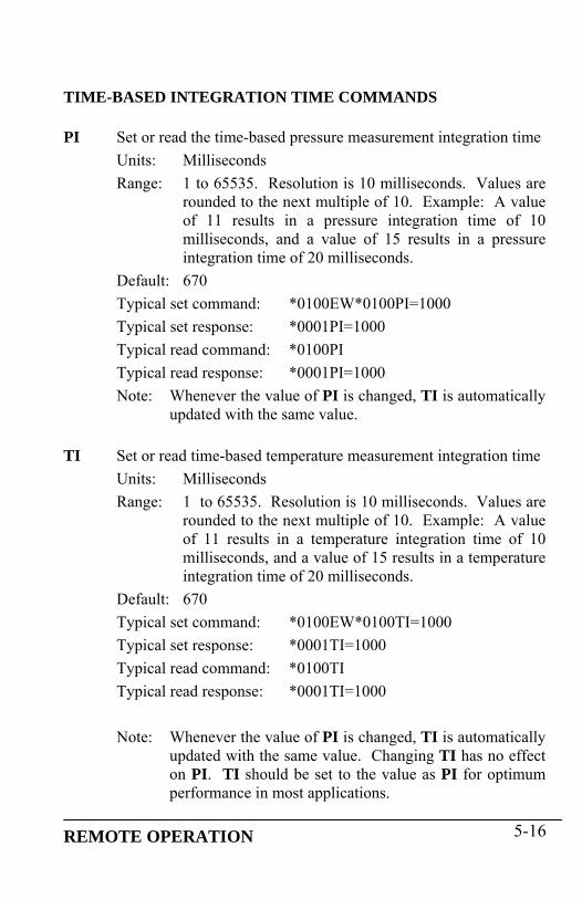
TIME-BASED INTEGRATION TIME COMMANDS PI Set or read the time-based pressure measurement integration time
Units: Milliseconds Range: 1 to 65535. Resolution is 10 milliseconds. Values are
rounded to the next multiple of 10. Example: A value of 11 results in a pressure integration time of 10 milliseconds, and a value of 15 results in a pressure integration time of 20 milliseconds.
Default: 670 Typical set command: *0100EW*0100PI=1000 Typical set response: *0001PI=1000 Typical read command: *0100PI Typical read response: *0001PI=1000 Note: Whenever the value of PI is changed, TI is automatically
updated with the same value.
TI Set or read time-based temperature measurement integration time Units: Milliseconds Range: 1 to 65535. Resolution is 10 milliseconds. Values are
rounded to the next multiple of 10. Example: A value of 11 results in a temperature integration time of 10 milliseconds, and a value of 15 results in a temperature integration time of 20 milliseconds.
Default: 670 Typical set command: *0100EW*0100TI=1000 Typical set response: *0001TI=1000 Typical read command: *0100TI Typical read response: *0001TI=1000 Note: Whenever the value of PI is changed, TI is automatically
updated with the same value. Changing TI has no effect on PI. TI should be set to the value as PI for optimum performance in most applications.
REMOTE OPERATION 5-16

PERIOD-BASED INTEGRATION TIME COMMANDS PR Set or read period-based pressure measurement integration time
Units: None Range: 1 to 16383 Default: 238 Typical set command: *0100EW*0100PR=200 Typical set response: *0001PR=200 Typical read command: *0100PR Typical read response: *0001PR=200 Note: Whenever the value of PR is changed, TR is
automatically updated with the value of PR times 4.
TR Set or read period-based temperature measurement integration time Units: None Range: 1 to 65535 Default: 952 Typical set command: *0100EW*0100TR=800 Typical set response: *0001TR=800 Typical read command: *0100TR Typical read response: *0001TR=800 Note: Whenever the value of PR is changed, TR is
automatically updated with the value of PR times 4. Changing TR has no effect on PR. TR should be set to the value as PR times 4 for optimum performance in most applications.
REMOTE OPERATION 5-17

5.7.2.3 Data Output Mode Command The following command controls whether pressure data is continuously output, and whether display data are produced. MD Set or read the data output mode.
Action: MD configures the Model 735/745 for continuous serial pressure measurement output and/or display data output whenever power is applied.
MD
valueDisplay data
output Continuous serial
pressure data output 0 OFF OFF 1 ON OFF 2 OFF ON 3 ON ON
Once MD is set, the specified data output mode will remain in effect until MD is set to a different value, even through a power cycle. Therefore, the Model 735/745 will perform the specified data output function whenever power is applied.
Range: 0-3 Default: 1 Typical set command: *0100EW*0100MD=1 Typical set response: *0001MD=1 Typical read command: *0100MD Typical read response: *0001MD=1
CAUTION If MD is set to 0 or 2, the front panel display will no longer be updated. For most applications, MD should only be set to 1 or 3. MD settings of 0 and 2 are supported only for compatibility with other Digiquartz® Intelligent Instruments.
REMOTE OPERATION 5-18

Note: When MD is set to a non-zero value, the specified data output mode will be preempted under the following conditions:
• Continuous serial pressure data output is suspended when a
measurement command is received. Continuous data output resumes when the measurement command is complete.
• Display data output is suspended when a period measurement command (P1, P2, P6, Q1, Q2, Q6) is received. Display data output resumes when the period measurement command is complete.
• Continuous pressure data output is suspended when a continuous measurement command (P2, P4, P7, Q2, Q4) is received, and resumes when the continuous measurement command is cancelled.
REMOTE OPERATION 5-19

5.7.2.4 Engineering Units Commands Engineering units commands are used to specify the engineering units to be used when calculating pressure or temperature values, and to configure the user-defined pressure unit. UN Set or read the pressure engineering units.
Action: Sets or queries the conversion factor by which all calculated pressure values are multiplied before being output. Setting UN to a non-zero value selects one of eight standard pressure units; 0 selects a user-defined unit whose conversion factor is specified by the UF command. UN also sets the units of the pressure data displayed by an optional Model 715 display.
Range: 0 to 8
UN value
Pressure units
psi multiplied by…
0 User-defined pressure unit Value of UF 1 psi 1.0000000 2 hPa (mbar) 68.94757 3 bar 0.06894757 4 kPa 6.894757 5 MPa 0.00689476 6 in Hg 2.036021 7 mm Hg (Torr) 51.71493 8 m H2O 0.7030696
Default: 1 Typical set command: *0100EW*0100UN=2 Typical set response: *0001UN=2 Typical read command: *0100UN Typical read response: *0001UN=2
REMOTE OPERATION 5-20

UF Set or read the user-defined pressure engineering units conversion factor. Action: When UN=0, calculated pressure values (psi) are
multiplied by the value of UF before being output, thus scaling the pressure values in the desired user-defined pressure units.
Range: -9999999 to 9999999 Default: 1.0000000 Typical set command: *0100EW*0100UF=2 Typical set response: *0001UF=2 Typical read command: *0100UF Typical read response: *0001UF=2.000000
TU Set or read the temperature engineering units. Action: Specifies the temperature units for Q3, Q4, Q5, and
displayed temperature data. Range: 0 = °C 1 = °F Default: 0 Typical set command: *0100EW*0100TU=1 Typical set response: *0001TU=1 Typical read command: *0100TU Typical read response: *0001TU=1 Note: Temperature is always calculated in °C, but it is converted to °F if TU=1.
5.7.2.5 Tare and Overpressure Commands Taring is the process of subtracting a specified value from pressure measurements. You may use a measured pressure as the tare value, or you may specify any desired value. Taring can be enabled, disabled, and locked out through the use of serial commands. RS-232 pressure measurement data can be formatted to include an indication when taring is in effect. Refer to the ZI command for more information.
REMOTE OPERATION 5-21

The overpressure command can be used to specify the overpressure alarm setpoint. When the overpressure setpoint is exceeded, the overpressure I/O line changes from logic low (0 VDC) to logic high (5.0 VDC) ZS Set or read the tare state parameter value.
Action: The three states of ZS are as follows: ZS=0 Taring function is off. ZS=1 Taring has been requested, but is not yet in effect. ZS=2 Taring is in effect ZS is set to 0 on power-up. If ZL=0 (taring is not locked out), taring can be requested by setting the ZS to 1. At the first pressure measurement following a tare request, the following sequence occurs: • The pressure value is stored in the ZV parameter. • The value of ZS is set to 2 to indicate that taring is in
effect. • The value of ZV is subtracted from all subsequent
pressure values until taring is turned off.
If taring is already in effect when a ZS=1 command is issued, the sequence described above occurs, and taring continues using a new value of ZV. Taring can be turned off by issuing a ZS=0 command.
Range: 0 to 2 Default: 0 Typical set command: *0100EW*0100ZS=1 Typical set response: *0001ZS=1 Typical read command: *0100ZS Typical read response: *0001ZS=1
REMOTE OPERATION 5-22

ZV Set or read the tare value. Action: Sets or queries the value that is subtracted from pressure
measurements when taring is activated. ZV can be set to any desired value when taring is in effect (ZS=2). Note, however, that if taring is subsequently requested, a new value will overwrite the ZV value you have set.
The value of ZV is set to 0 on power-up. Range: -9999999 to 9999999 Default: 0 Typical set command: *0100EW*0100ZV=14.7123 Typical set response: *0001ZV=14.7123 Typical read command: *0100ZV Typical read response: *0001ZV=14.7123
ZL Set or read the tare lockout parameter value.
Action: When ZL=0, ZS can be set to enable and disable taring. When ZL=1, taring is locked, and the value of ZS cannot be modified via serial commands or the Tare Input I/O line. However, if ZS=1 and a ZL=1 command is issued, taring will be in effect when the next pressure measurement is taken, but you cannot turn taring off until ZL is set to 0.
The value of ZL is set to 0 on power-up. Range: 0 or 1 Default: 0 Typical set command: *0100EW*0100ZL=1 Typical set response: *0001ZL=1 Typical read command: *0100ZL Typical read response: *0001ZV=1
REMOTE OPERATION 5-23

OP Set or read the overpressure alarm setpoint value. Action: When a pressure measurement value is less than the value
of OP, the overpressure I/O line is at logic low (0 VDC) and the overpressure alert is silent; if it is greater or equal to the value of OP, the overpressure I/O line is set to logic high (5.0 VDC), and the overpressure alert sounds.
OP is set in the current pressure units, and is scaled accordingly if the engineering units are changed.
Range: -9999999 to 9999999 Default: Maximum rated unit pressure Typical set command: *0100EW*0100OP=15 Typical set response: *0001OP=15.00000 Typical read command: *0100OP Typical read response: *0001OP=15.00000
5.7.2.6 Measurement Data Formatting Commands These commands are used to alter the format of serial measurement data. The following data formatting functions are available:
• Append engineering units to pressure and temperature measurement data
• Append a taring indication to tared pressure measurement data • Add underscores to separate the measurement data from the rest
of the serial output data string to improve readability • Add trailing zeroes to the measurement data to create a fixed-
length data string to simplify parsing Formatting commands can be used separately or in any combination.
REMOTE OPERATION 5-24
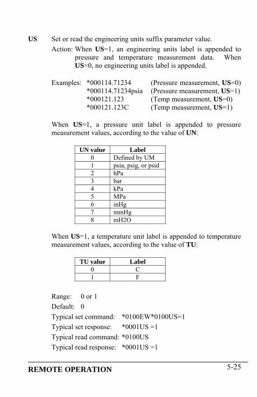
US Set or read the engineering units suffix parameter value. Action: When US=1, an engineering units label is appended to
pressure and temperature measurement data. When US=0, no engineering units label is appended.
Examples: *000114.71234 (Pressure measurement, US=0) *000114.71234psia (Pressure measurement, US=1) *000121.123 (Temp measurement, US=0) *000121.123C (Temp measurement, US=1)
When US=1, a pressure unit label is appended to pressure measurement values, according to the value of UN:
UN value Label
0 Defined by UM 1 psia, psig, or psid 2 hPa 3 bar 4 kPa 5 MPa 6 inHg 7 mmHg 8 mH2O
When US=1, a temperature unit label is appended to temperature measurement values, according to the value of TU:
TU value Label
0 C 1 F
Range: 0 or 1 Default: 0 Typical set command: *0100EW*0100US=1 Typical set response: *0001US =1 Typical read command: *0100US Typical read response: *0001US =1
REMOTE OPERATION 5-25

SU Set or read the underscore separator parameter value.
Action: When SU=1, an underscore separates the measurement data from the address header and the optional engineering units suffix. When SU=0, no underscore separators appear.
Examples: *000114.71234 (SU=0) *0001_14.71234 (SU=1) *0001_14.71234_psia (SU=1, US=1)
Range: 0 or 1 Default: 0 Typical set command: *0100EW*0100SU=1 Typical set response: *0001SU=1 Typical read command: *0100SU Typical read response: *0001SU=1
ZI Set or read the taring indication parameter value.
Action: When ZI=1, a “T” is appended to pressure measurement values when taring is in effect. When ZI=0, no taring indication appears, whether taring is in effect or not.
Examples: *000114.71234 (ZI=0) *000114.71234T (ZI=1) *0001_14.71234T (ZI=1, SU=1) *000114.71234Tpsia (ZI=1, US=1) *0001_14.71234T_psia (ZI=1, US=1, SU=1)
Range: 0 or 1 Default: 0 Typical set command: *0100EW*0100ZI=1 Typical set response: *0001ZI=1 Typical read command: *0100ZI Typical read response: *0001ZI=1
REMOTE OPERATION 5-26

DL Set or read the fixed field data format parameter.
Action: When DL=1, measurement data is formatted in a fixed field format. When DL=0, measurement data is given in the standard format.
The fixed field format is specified as follows: *AAAASDDDDDDDDDD, where
* = the asterisk character A = destination and source address characters S = sign of pressure data, either + or –
D = numeric representation of pressure data, either digits or a decimal point
Examples: *000114.71234 (Pressure, DO=0) *0001+14.7123400 (Pressure, DO=1) *000121. 123 (Temperature, DO=0) *0001+21.1230000 (Temperature, DO=1)
Range: 0 or 1 Default: 0 Typical set command: *0100EW*0100DL=1 Typical set response: *0001DL=1 Typical read command: *0100DL Typical read response: *0001DL=1 Note: The format specification and examples shown above
assume that the other formatting commands are disabled. If other formatting commands are used in combination with DL, a fixed field format will still result, but the format specification will vary slightly from the one described above.
REMOTE OPERATION 5-27

UM Set or read the user-defined engineering units label parameter.
Action: When UN=0 and US=1, the text value of UM is appended to pressure measurements.
Examples: *000114.71234 (UN=0, US=0) *000114.71234user (UN=0, US=1, UM=user)
Range: Any text up to four characters, consisting of ASCII 32 to ASCII 127.
Default: user Typical set command: *0100EW*0100UM=test Typical set response: *0001UM=test Typical read command: *0100UM Typical read response: *0001UM=test
5.7.2.7 Unit Identification Commands The Unit Identification commands read various device-specific parameters. These parameters are factory-set, and cannot be modified. SN Read the serial number.
Action: The SN parameter contains the device serial number. SN is a read-only command.
Typical read command: *0100SN Typical read response: *0001SN=12345
VR Read the firmware version number. Action: The VR parameter contains the device firmware version
number. VR is a read-only command.
Typical read command: *0100VR Typical read response: *0001VR=D1.02
REMOTE OPERATION 5-28

MN Read the model number. Action: The MN parameter contains the device model number as
a text string. The value of MN always contains 16 characters. If the model number is less than 16 characters, the string will be padded with trailing spaces to a length of 16 characters. MN is a read-only command.
Typical read command: *0100MN Typical read response: *0001MN=745-15A
PF Read the full-scale pressure value.
Action: The PF parameter contains the full-scale pressure value in the current pressure units. If the units are changed, the value of PF is scaled accordingly. PF is a read-only command.
Typical read command: *0100PF Typical read response: *0001PF=30.00000
PO Read the pressure transducer type.
Action: The PO parameter contains the pressure transducer type. PO is a read-only command.
PO value Transducer type
0 Absolute 1 Gauge 2 Differential
Typical read command: *0100PO Typical read response: *0001PO=0
REMOTE OPERATION 5-29

5.7.2.8 Display Data Configuration Commands The Display Configuration commands allow you to alter the information shown on the display. They also control the display of the optional Model 715 Remote Display. DP Set or read the maximum number of decimal places in the
displayed pressure value. Action: DP sets the maximum number of decimal places in the
displayed pressure value. Fewer decimal places will be displayed if the pressure resolution and/or pressure unit will not provide the specified number of decimal places. When DP is set to 6, the maximum number of decimal places is always displayed, according to current pressure resolution.
Range: 0 to 6 Default: 6 Typical set command: *0100EW*0100DP=6 Typical set response: *0001DP=6 Typical read command: *0100DP Typical read response: *0001DP=6
DT Set the text to be displayed on the second line when the External
Text display option is selected from the Configuration Menu. Use DT when the Model 735/745 is to be controlled by an RS-232 serial host, and the text must be updated frequently. Action: DT allows a serial host (such as a PC) to send text to be
displayed on the bottom line. The text sent using DT is not stored by the Model 735/745; it is simply transferred to its display. DT cannot be queried, and it is not necessary to precede DT with an EW command. The text is lost when the Model 735/745 is powered off.
Range: 16 characters maximum. Any characters in the range of ASCII 32 to ASICC 127 are legal.
Typical set command: *0100DT=This is my text Typical set response: *0001DT=This is my text
REMOTE OPERATION 5-30

PL Read the overpressure indication setpoint. This setpoint is used
to determine the pressure at which the overpressure indication is displayed. PL is a factory-set, read-only command. Action: When the Model 735/745 measures a pressure greater
than the value of PL, an overpressure indication is displayed.
Typical read command: *0100PL Typical read response: *0001PL=120.0000 Note: PL is typically factory-set to the overpressure limit as
specified in the Specification Control Drawing for the Digiquartz® transducer.
UL Set or read the text to be displayed on the second line when the
Stored Text display option is selected from the Configuration Menu.
Action: UL defines the text to be displayed on the bottom line.
The value of UL is stored in non-volatile memory, and will therefore be retained even if power is lost.
Range: 11 characters maximum. Any characters in the range of ASCII 32 to ASCII 127 are legal.
Default: 11 space characters Typical set command: *0100EW*0100UL=My label Typical set response: *0001UL=My label Typical read command: *0100UL Typical read response: *0001UL=My label CAUTION Do not use UL if it is necessary to update the displayed text often; use the External Text display option and the DT command instead. The nonvolatile memory used to store the text data can be written approximately 100,000 times; excessive use of UL will eventually result in the inability to change its value.
REMOTE OPERATION 5-31

5.7.2.9 Calibration Commands The calibration commands set and read several parameters that directly affect the measurement accuracy of the device. Refer to Section 10 for more information regarding the use of the calibration parameters. CAUTION Calibration values should be modified only when absolutely necessary, and then with extreme caution. Calibration adjustments should only be performed by a qualified metrology lab. PA and PM are used in the following formula to calculate final output pressure:
Padjusted = PM * (P + PA)
Where: P = Pressure calculated using original calibration coefficients, in the current pressure units
PM = the current value of the PM parameter
PA = the current value of the PA parameter
PA Set or read the pressure adder parameter.
Action: The pressure adder parameter is used to make zero adjustments to the calibration. PA can also be used to offset absolute pressure measurements by atmospheric pressure to obtain gauge pressure.
Range: -9999999 to 9999999 Default: 0.0 Typical set command: *0100EW*0100PA=.0000123 Typical set response: *0001PA=.0000123 Typical read command: *0100PA Typical read response: *0001PA=.0000123
REMOTE OPERATION 5-32

Note: The value of PA is entered in the current pressure units, but is converted to psi prior to being stored. When PA is queried, it returns the value scaled to the current pressure units.
PM Set or read the pressure multiplier parameter.
Action: The pressure multiplier parameter is used to make span adjustments to the calibration.
Range: -9999999 to 9999999 Default: 1 Typical set command: *0100EW*0100PM=1.000123 Typical set response: *0001PM=1.000123 Typical read command: *0100PM Typical read response: *0001PM=1.000123
Note: The value of PM is dimensionless, and is therefore not
scaled if the units are changed.
TC Read the crystal timebase correction factor.
Action: TC is used to normalize the nominal 14.7456 MHz reference crystal frequency to 10 MHz to compensate for the natural variation in reference crystal resonant frequency. TC is a read-only command.
Typical read command: *0100TC Typical read response: *0001TC=.6666667
REMOTE OPERATION 5-33

C1 C2 C3 D1 D2 T1 T2 T3 T4 T5 U0 Y1 Y2 Y3
Set or read the calibration coefficients. See paragraph 7.8 and Section 10 for more information about calibration and calibration coefficients.
Default: Device-specific Typical set command: *0100EW*0100C1=228.1234 Typical set response: *0001C1=228.1234 Typical read command: *0100C1 Typical read response: *0001C1=228.1234
5.7.2.10 Diagnostic Commands In the unlikely event of a hardware failure, the diagnostic commands can assist in the troubleshooting process. CS Read the number of unused bytes on the stack since power-up.
Action: CS is read-only; it cannot be set. It can be used to determine whether a stack overflow may have occurred.
Typical read command: *0100CS Typical read response: *0001CS=8
REMOTE OPERATION 5-34
CX Check timebase crystal frequency.
Action: Puts the timebase frequency divided by 480 on the Tare Output I/O line. The timebase signal is removed from the Tare Output I/O line when the next valid command is received. CX cannot be queried. The CX set command does not produce a response.
Typical set command: *0100CX Typical set response: No response
5.7.2.11 Global Commands Under certain circumstances, it may be desirable to send a single command to multiple units on a serial loop network. The ID 99 has been reserved for such global addressing. When a Model 735/745 receives a legal command addressed to ID 99, it reacts to that command regardless of its assigned ID value. When the Model 735/745 receives a global command via RS-232, it retransmits the global command before acting on it. This ensures that all units on a serial loop will receive the global command. Eventually, the global command is retransmitted by the last unit in the serial loop and is received by the serial host. The serial host must be able to disregard the retransmitted command. Global addressing is often used with sample and hold measurement commands to synchronize measurements from multiple devices. The sample and hold measurement commands are: P5 and P6 Q5 and Q6
REMOTE OPERATION 5-35

All sampling commands and certain other commands may be either individually or globally addressed: P1 through P7 Q1 through Q6 DB VR EW The remaining commands should not be sent as global commands
5.8 High Speed Sampling Use one or more of the following techniques to increase the RS-232 sampling rate.
• Reduce integration time. Refer to PI, TI, PR, and TR commands in paragraph 5.7.2.2.
• Use PR and TR rather than PI and TI to control integration time. PR and TR have approximately 1ms resolution, compared to 10ms of PI and TI. See paragraph 5.7.2.2 for details
• Use a continuous pressure measurement command, such as P4 or P7. See paragraph 5.7.1.3 for details.
• Turn off display data output. Refer to the MD command in paragraph 5.7.2.3.
• Increase the baud rate. Refer to paragraph 4.1.4.4. • Use the continuous pressure period command (P2), and post-
process data to convert to pressure. Refer to paragraph 7.8 for detailed information about converting period measurements into pressure values.
5.9 Networking The Model 735/745 supports RS-232 serial loop networking. Networking allows you to communicate with up to 98 Digiquartz® Intelligent devices from a single RS-232 serial host.
REMOTE OPERATION 5-36
5.9.1 Networking Basics When setting up a network, the following points must be observed.
• If your network includes older Intelligent transmitters that support RS-232 only, set the older devices to PT = N to assure compatibility with the Model 735/745.
• Verify proper operation of each Intelligent device before installing it in a network.
• Set all Intelligent devices to the same baud rate before installing them in a network.
• Each Intelligent device on the network needs to be set to a unique ID.
5.9.2 RS-232 Loop Networking Refer to Figure 4. In an RS-232 serial loop network, the transmit output of the RS-232 host is connected to the receive input of the first device in the loop. The transmit output of the first device is connected to the receive input of the next device. The remaining devices are connected similarly, with their receive input connected to the transmit output of the previous device, and their transmit output connected to the receive input of the next device. The transmit output of the last device is connected to the receive input of the RS-232 host. The host sends commands to the first device in the loop. If a command is addressed to that device, the command is carried out; if not, the command is resent to the next device. Globally addressed commands are carried out by each device, and are also resent to the next device. When a device responds to a command, the response is addressed to the host, and is therefore resent by each device that receives it until it eventually makes it way to the serial host.
REMOTE OPERATION 5-37

Figure 4. Serial loop network block diagram Keep these points in mind when designing an RS-232 serial loop network:
• As previously described, each device resends any command or response that is addressed to another device. Since each device considers resending to be a higher priority than sending its own response, it is possible that a device can spend all its time resending, and never have an opportunity to send its own response. This occurs only when one or more upstream devices are continuously transmitting. To prevent this situation: • Operate your network at 9,600 baud or above • Avoid continuous transmission (P2, P4, P7, Q2, and Q4
commands) at extremely low integration times
• It is not possible to precisely synchronize measurements from two or more devices by sending a global measurement command. This is a result of the delay that occurs as the measurement command propagates through the serial loop.
• When a global command is sent, it propagates through the serial
loop, eventually making its way back to the host. Therefore, the data received by the host in response to a global command includes the command itself, followed by the individual responses from all devices on the network.
REMOTE OPERATION 5-38

REMOTE OPERATION 5-39
5.10 Displaying Data Remotely with Model 715 Display
The Model 715 Display can be used to replicate the Model 735/745 display data at a distance of up to 4000 feet. The Model 715 display is identical to that of the Model 735/745, with the following exceptions:
• Pressure rate of change data cannot be displayed on the Model 715. If the Model 735/745 is set up to display pressure rate of change, the second line of the Model 715 will not be updated.
• When the Model 735/745 configuration menu is accessed, the
Model 715 will not display the configuration menu, but will continue to display pressure values.
Using the Model 715 with the Model 735/745 is simple and easy. Simply connect the units as shown in paragraph 0. Turn on the Model 735/745; then turn on the Model 715. The Model 715 will automatically synchronize its baud rate to that of the Model 735/745; this may take as much as a few minutes. When the Model 715 has synchronized, it will begin to replicate the Model 735/745 display.

6 Nano-Resolution Features & Functions
6.1 Introduction With firmware revision D1.06 or later, it is now possible to achieve parts-per-billion resolution (nano-resolution). This feature can be enabled by software command. When disabled, the sensor is backward compatible and works in the standard mode with typical parts-per-million resolution. Nano-resolution is achieved by sub-sampling the pressure at a much higher rate (typically 8 kHz) and applying digital signal processing techniques. Because of the much higher processing requirements, more input power is required. In general, the nano-resolution feature is only useful if the pressure is stable enough over the effective sampling period and if the data acquisition system can handle additional digits. The practical bandwidth of interest is in the infrasound and deep infrasound (10 to 0.001 Hz). Two methods for nano-resolution are available. The first method processes the sub-samples in a finite time interval (analogous to the integration time of the standard mode). The digital process is an FIR filter (finite impulse response). The resolution can be directly compared to the resolution of the standard mode at the same sampling rate (synchronized). The algorithm performs a least-squares (regression) fit over the sub-samples to estimate the best value of pressure. While the resolution is statistically two orders of magnitude better than the standard mode, it does not suppress aliasing errors. A second and usually preferred method is the IIR filter (infinite impulse response). It consists of a 5-stage digital low-pass filter acting on the sub-samples. It filters all frequencies with a roll-off of -100 dB/decade above a user selectable cutoff frequency. It is an effective anti-aliasing filter. The inherent resolution depends on the cutoff frequency and not on the sampling period. Typically, the sampling rate is set at twice the cutoff frequency (Nyquist limit).
NANO-RESOLUTION FEATURES & FUNCTIONS 6-1

6.2 Enabling Nano-Resolution Nano-resolution can be enabled and disabled by the XM serial command. XM Set or read the resolution mode.
Range: 0 = Standard Resolution Mode (backward compatible) 1 = Nano-resolution, IIR Filter Mode 2 = Nano-resolution, FIR Filter Mode Default: 0 Typical set command: *0100EW*0100XM=1 Typical set response: *0001XM=1 Typical read command: *0100XM Typical read response: *0001XM=1
6.3 Configuring IIR Filter Mode SETTING RESOLUTION Resolution is a function of the cutoff frequency when operating in IIR mode. The cutoff frequency is user-selectable and is set by the IA command. IA Set or read the cutoff frequency setting.
Range: 0 - 16 Default: 11 Typical set command: *0100EW*0100IA=11 Typical set response: *0001IA=11 Typical read command: *0100IA Typical read response: *0001IA=11
See Table 1 for a list of ranges for IA values, cutoff frequencies, measurement resolution, and the number of digits reported via RS-232.
NANO-RESOLUTION FEATURES & FUNCTIONS 6-2

Table 1: IIR Filter Mode Typical Resolution Ranges I
A
(1) Cu
toff
Fre
quen
cy(2
) Effe
ctiv
e
Tim
e In
terv
al
(3) Pe
riod
Re
solu
tion
(4) M
easu
rand
Re
solu
tion
(4) M
easu
rand
Re
solu
tion
(5) Pr
essu
re &
Te
mp.
Dig
its
(Hz) (ms) (dB) (dB) (ppm/ppb)
0 1400 0.1 -82 -62 790 ppm 61 700 1 -94 -74 200 ppm 72 350 2 -105 -85 56 ppm 73 175 3 -117 -97 14 ppm 84 88 6 -127 -107 4.5 ppm 85 44 11 -140 -120 1.0 ppm 86 22 22 -149 -129 0.35 ppm 97 11 44 -157 -137 0.14 ppm 98 5.5 89 -167 -147 45 ppb 109 2.8 178 -177 -157 14 ppb 1010 1.4 350 -186 -167 4.5 ppb 1111 0.7 700 -196 -176 1.6 ppb 1112 0.35 1400 -203 -183 0.7 ppb 1213 0.18 2800 -206 -186 0.5 ppb 1214 0.09 5600 -207 -187 0.4 ppb 1215 0.045 11200 -207 -187 0.4 ppb 1216 0.023 22400 -207 -187 0.4 ppb 12
(1) Cutoff frequency is the -3dB point of the low-pass IIR filter. (2) Effective Time Interval is the recommended minimum time interval between measurements that ensures sampling up to the specified cutoff frequency. The time interval is set using the PI command. (3) Period Resolution is the resolution of pressure and temperature period measurements. (4) Measurand Resolution is the resolution of pressure and temperature measurements. (5) Pressure and Temperature Digits is the total number of digits used to report pressure and temperature measurements. Pressure and temperature period measurements contain one additional digit.
NANO-RESOLUTION FEATURES & FUNCTIONS 6-3

6.4 Configuring FIR Filter Mode SETTING RESOLUTION Resolution is a function of the integration time when operating in FIR mode. The integration time is set by the PI command. Refer to page 5.7.2.2 for more information about the PI command. Table 2 lists various PI values and the resulting measurement resolution for pressure period, pressure, and the number of digits reported via RS-232.
Table 2: FIR Filter Mode Typical Resolution Ranges
PI
(1) Pe
riod
Res
olut
ion
(2) M
easu
rand
Re
solu
tion
(2) M
easu
rand
R
esol
utio
n(3
) Pres
sure
&
T
emp
Digi
ts(ms) (dB) (dB) (ppm/ppb)
1 -105 -85 56.2 ppm 62 -114 -94 19.9 ppm 73 -119 -99 10.8 ppm 76 -128 -108 3.8 ppm 8
11 -136 -116 1.5 ppm 822 -145 -125 544.5 ppb 844 -154 -134 192.5 ppb 989 -163 -143 66.9 ppb 9
178 -173 -153 23.7 ppb 10350 -181 -161 8.6 ppb 10700 -190 -170 3.0 ppb 11
1400 -199 -179 1.1 ppb 112800 -206 -186 0.5 ppb 125600 -206 -186 0.5 ppb 12
11200 -206 -186 0.5 ppb 1322400 -206 -186 0.5 ppb 13
(1) Period Resolution is the resolution of pressure and temperature period measurements. (2) Measurand Resolution is the statistical resolution limit of the FIR algorithm for pressure and temperature
NANO-RESOLUTION FEATURES & FUNCTIONS 6-4
measurements. The trigger error typically doubles the least resolution. (3) Pressure and Temperature Digits is the total number of digits used to report pressure and temperature measurements. Pressure and temperature period measurements contain one additional digit up to a maximum of 13 digits.
TEMPERATURE SMOOTHING The temperature smoothing function is available for additional low-pass filtering of the temperature signal, mostly to avoid very rare and small aliasing errors from digital rounding in the FIR mode. The XT command enables and disables the smoothing function and controls the corner frequency of the low-pass filter. Normally, the default setting should always be XT=1 (no smoothing). If temperature smoothing is desired, a setting of XT=10 is suggested. Temperature smoothing is performed per the following formula: Sn = αTn + (1 – α) S(n-1) Where Sn = smoothed temperature Tn = measured temperature S(n-1) = smoothed temperature of previous sample α = 1/(XT) XT Set or read the number of temperature measurements to use
for temperature smoothing in FIR Mode.
Range: 1 - 100 Default: 1 (no smoothing) Typical set command: *0100EW*0100XT=10 Typical set response: *0001XT=10 Typical read command: *0100XT Typical read response: *0001XT=10
NANO-RESOLUTION FEATURES & FUNCTIONS 6-5

6.5 Default Numeric Formats for IIR & FIR Modes The default numeric formats used to report period, pressure, and temperature measurement values via the display and/or RS-232 port are as follows, where N = the number of significant digits shown in the resolution tables. Note: The Model 735/745 can display a maximum of 10 significant digits. Values with greater than 10 digits will be rounded as required. PRESSURE The sensor full-scale pressure defines the number of digits reserved for the integer portion of the pressure value. For example, a 1000 psi full-scale unit would have 4 digits reserved (but not necessarily used) for the integer portion of the pressure value, leaving N-4 digits for the fractional portion. TEMPERATURE Three digits are reserved (but not necessarily used) for the integer portion of the temperature value, leaving N-3 digits for the fractional portion. Negative temperature values include a sign but the numeric format is otherwise unaffected. PRESSURE PERIOD Two digits are used for the integer portion of the pressure period value, leaving N-2 digits for the fractional portion. TEMPERATURE PERIOD One digit is used for the integer portion of the pressure period value, leaving N-1 digits for the fractional portion.
6.6 Controlling the Numeric Format The XN command sets the number of significant digits used to report period, pressure, and temperature measurement values. The XN command overrides the default numeric format.
NANO-RESOLUTION FEATURES & FUNCTIONS 6-6

NANO-RESOLUTION FEATURES & FUNCTIONS 6-7
XN Set or read the number of significant digits displayed and/or output.
Range: 0 - 13 Default: 0 Typical set command: *0100EW*0100XN=10 Typical set response: *0001XN=10 Typical read command: *0100XN Typical read response: *0001XN=10
When XN is set to 0, the default numeric formats are used. When non-zero, XN specifies the number of significant digits used to report period, pressure, and temperature measurement values. With the exception of the total number of digits, all default format characteristics apply. The integer portion is never expressed with fewer digits than required regardless of the value of XN. The fractional portion is rounded or padded with zeros as required to fit the specified format. The XN command works with Standard, IIR, and FIR resolution modes. Note: The Model 735/745 can display a maximum of 10 significant digits. Values with greater than 10 digits will be rounded as required.

7 Pressure Measurement Concepts 7.1 Measurement Basics At the heart of all Digiquartz® Intelligent Instruments is a precision Digiquartz® pressure transducer. The outputs from a Digiquartz® pressure transducer are two square wave signals whose period is proportional to applied pressure and internal transducer temperature. The Model 735/745 measures these signals using a technique similar to that of a common laboratory frequency counter. Like the frequency counter, a signal must be integrated, or sampled, for a specified period of time to measure its period. The time over which the signal is sampled determines the resolution of the measurement. Longer sampling times increase resolution, but result in a slower sampling rate. The Model 735/745 allows you to set the integration time between 0.001 and 65.535 seconds. Pressure and temperature integration times can be set independently. You can use these features to configure the unit according to the data acquisition and resolution requirements of your application. Refer to paragraph 7.6 for more information about integration time, resolution, and sampling rate.
7.2 Measurement Types One or both of the Digiquartz® pressure transducer output signals are sampled, depending on the type of measurement requested. Four types of measurements can be taken:
• Pressure • Internal sensor temperature • Pressure period • Temperature period
Pressure measurements are displayed by the Model 735 and 745. The other types of measurements can only be accessed via the RS-232 port.
PRESSURE MEASUREMENT CONCEPTS 7-1

PRESSURE MEASUREMENTS Pressure measurements are the most common. Pressure measurement values are displayed on the top line of the Model 735/745 display, and can also be output via RS-232. Pressure measurements are fully temperature-compensated, and therefore require an internal temperature measurement. When a pressure measurement is made, the following sequence occurs:
• The temperature signal period is measured • An internal transducer temperature value is calculated using
the temperature period and the calibration coefficients • The pressure signal period is measured • A temperature-compensated pressure value is calculated
using the pressure period, temperature value, and the calibration coefficients
• The pressure value is displayed and optionally output via RS-232
INTERNAL SENSOR TEMPERATURE MEASUREMENTS Internal sensor temperature is normally only used for temperature compensation of pressure, but can be requested independently for diagnostic and other purposes. Internal sensor temperature measurements can optionally be displayed on the bottom line of the Model 735/745 display, and can also be output via RS-232. When an internal sensor temperature measurement is made, the following sequence occurs:
• The temperature signal period is measured • A temperature value is calculated using the temperature
period and the calibration coefficients • The temperature value is optionally displayed and/or output
via RS-232
PRESSURE MEASUREMENT CONCEPTS 7-2

PRESSURE AND TEMPERATURE PERIOD MEASUREMENTS Period measurements are used mainly for calibration and diagnostic purposes, but may be useful in high-speed sampling applications. Period measurements can only be accessed via the RS-232 port. When a period measurement is made, the following sequence occurs:
• The pressure or temperature signal period is measured • The period value is output
Refer to paragraph 5.7 for detailed measurement command descriptions.
7.3 Sampling Types Measurement data can be sampled via the RS-232 port by the following methods:
• Single measurement • Continuous measurement • High-speed continuous measurement • Sample and hold measurement
SINGLE MEASUREMENT SAMPLING Single measurement sampling commands output a single measurement value each time the command is received.
CONTINUOUS MEASUREMENT SAMPLING Continuous measurement sampling commands repeatedly output measurement data until commanded to stop.
HIGH-SPEED CONTINUOUS MEASUREMENT SAMPLING Similar to regular continuous measurement commands, but internal transducer temperature measurements are taken only occasionally. This type of sampling is useful when sampling rates must be as high as possible, and is particularly effective when internal transducer temperature is not expected to change significantly.
PRESSURE MEASUREMENT CONCEPTS 7-3

SAMPLE AND HOLD MEASUREMENT SAMPLING Similar to single measurement sampling, but the measurement value is not output until a separate command is sent. This type of sampling is useful when you need to simultaneously trigger measurements from multiple units, and then read them one by one in a particular order. Refer to paragraph 5.7 for detailed measurement command descriptions.
7.4 Engineering Units Pressure values can be expressed in the following engineering units. Refer to the UN command in paragraph 5.7.2.4 for details.
• psi • hPa (mbar) • bar • kPa • MPa • in Hg • mm Hg (Torr) • m H2O • User-defined pressure units
Temperature values can be expressed in the following units. Refer to the TU command in paragraph 5.7.2.4 for details.
• °C • °F
7.5 Tare Function You can configure the Model 735/745 to subtract a value from each subsequent pressure measurement. This process is referred to as taring. You can tare subsequent pressure measurements to the current pressure value, or to any value you specify. Taring can be enabled and disabled through the configuration menu or by serial command. An indicator on the display and/or a special character in the RS-232 measurement data indicates when taring is in effect. Refer to paragraphs 5.7.2.5 and 5.7.2.6 for details.
PRESSURE MEASUREMENT CONCEPTS 7-4

7.6 Resolution, Integration Time and Sampling Rate
7.6.1 Definitions RESOLUTION Resolution is defined as the smallest change in measured quantity that can be detected.
INTEGRATION TIME Integration time is defined as the length of time that a Digiquartz® pressure transducer output signal is sampled to produce a single measurement value.
SAMPLING RATE Sampling rate is defined as the number of measurements that can be taken in a given period of time.
7.6.2 Interdependencies Resolution, integration time, and sampling rate are interdependent. This is due to the method by which the Model 735/745 measures the outputs from the Digiquartz® pressure transducer. The integration time determines the resolution of the measurement. Longer integration times increase resolution, but reduce the sampling rate. Conversely, shorter integration times decrease resolution, but increase the sampling rate. Another factor that influences sampling rate is the serial baud rate. For short integration times, faster baud rates enable faster sampling. As integration times increase, the benefit of faster baud rates quickly diminishes. Baud rate has no effect on integration time, and therefore has no effect on resolution. Tables 1, 2, and 3 illustrate the relationship between integration time, resolution, and sampling rate for the P2, P4, and P7 commands at common baud rates.
PRESSURE MEASUREMENT CONCEPTS 7-5
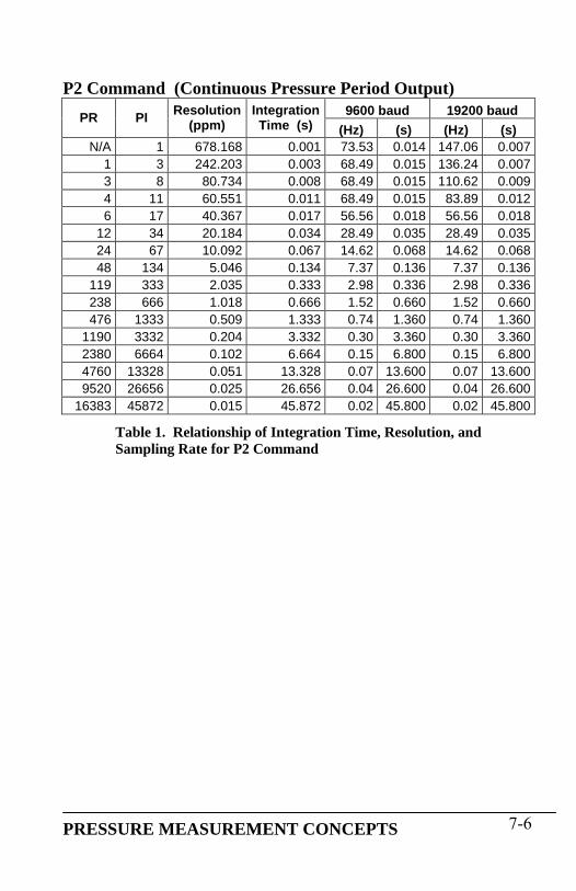
P2 Command (Continuous Pressure Period Output) 9600 baud 19200 baud PR PI Resolution
(ppm) IntegrationTime (s) (Hz) (s) (Hz) (s)
N/A 1 678.168 0.001 73.53 0.014 147.06 0.0071 3 242.203 0.003 68.49 0.015 136.24 0.0073 8 80.734 0.008 68.49 0.015 110.62 0.0094 11 60.551 0.011 68.49 0.015 83.89 0.0126 17 40.367 0.017 56.56 0.018 56.56 0.018
12 34 20.184 0.034 28.49 0.035 28.49 0.03524 67 10.092 0.067 14.62 0.068 14.62 0.06848 134 5.046 0.134 7.37 0.136 7.37 0.136
119 333 2.035 0.333 2.98 0.336 2.98 0.336238 666 1.018 0.666 1.52 0.660 1.52 0.660476 1333 0.509 1.333 0.74 1.360 0.74 1.360
1190 3332 0.204 3.332 0.30 3.360 0.30 3.3602380 6664 0.102 6.664 0.15 6.800 0.15 6.8004760 13328 0.051 13.328 0.07 13.600 0.07 13.6009520 26656 0.025 26.656 0.04 26.600 0.04 26.600
16383 45872 0.015 45.872 0.02 45.800 0.02 45.800
Table 1. Relationship of Integration Time, Resolution, and Sampling Rate for P2 Command
PRESSURE MEASUREMENT CONCEPTS 7-6

P4 Command (Continuous Pressure Output) 9600 baud 19200 baud PR PI Resolution
(ppm) IntegrationTime (s) (Hz) (s) (Hz) (s)
N/A 1 678.168 0.001 79.62 0.013 159.24 0.0061 3 242.203 0.003 79.62 0.013 153.37 0.0073 8 80.734 0.008 60.35 0.017 60.35 0.0174 11 60.551 0.011 46.08 0.022 46.08 0.0226 17 40.367 0.017 30.49 0.033 30.49 0.033
12 34 20.184 0.034 15.58 0.064 15.58 0.06424 67 10.092 0.067 7.96 0.126 7.96 0.12648 134 5.046 0.134 4.07 0.246 4.07 0.246
119 333 2.035 0.333 1.64 0.608 1.64 0.608238 666 1.018 0.666 0.82 1.220 0.82 1.220476 1333 0.509 1.333 0.41 2.440 0.41 2.440
1190 3332 0.204 3.332 0.16 6.080 0.16 6.0802380 6664 0.102 6.664 0.08 12.160 0.08 12.1604760 13328 0.051 13.328 0.04 24.300 0.04 24.3009520 26656 0.025 26.656 0.02 48.600 0.02 48.600
16383 45872 0.015 45.872 0.01 83.600 0.01 83.600
Table 2. Relationship of Integration Time, Resolution, and Sampling Rate for P4 Command
PRESSURE MEASUREMENT CONCEPTS 7-7

P7 Command (Fast Continuous Pressure Output)
9600 baud 19200 baud PR PI Resolution(ppm)
IntegrationTime (s) (Hz) (s) (Hz) (s)
N/A 1 678.168 0.001 79.62 0.013 159.24 0.0061 3 242.203 0.003 79.62 0.013 159.24 0.0063 8 80.734 0.008 73.53 0.014 107.30 0.0094 11 60.551 0.011 73.53 0.014 81.97 0.0126 17 40.367 0.017 55.25 0.018 55.25 0.018
12 34 20.184 0.034 28.25 0.035 28.25 0.03524 67 10.092 0.067 14.53 0.069 14.53 0.06948 134 5.046 0.134 7.37 0.136 7.37 0.136
119 333 2.035 0.333 2.98 0.336 2.98 0.336238 666 1.018 0.666 1.52 0.660 1.52 0.660476 1333 0.509 1.333 0.74 1.360 0.74 1.360
1190 3332 0.204 3.332 0.30 3.360 0.30 3.3602380 6664 0.102 6.664 0.15 6.800 0.15 6.8004760 13328 0.051 13.328 0.07 13.600 0.07 13.6009520 26656 0.025 26.656 0.04 26.800 0.04 26.800
16383 45872 0.015 45.872 0.02 45.800 0.02 45.800
Table 3. Relationship of Integration Time, Resolution, and Sampling Rate for P7 Command, PS=0
PRESSURE MEASUREMENT CONCEPTS 7-8

7.7 High Speed Sampling See paragraph 5.8 for techniques that can be used to increase sampling rate.
7.8 Calculations and Formulas The Model 735/745 calculates internal sensor temperature and temperature-compensated pressure from period measurements of the Digiquartz® pressure transducer output signals. The equations and coefficients used to perform these calculations are given below. The Model 745 is initialized with its transducer coefficients at the factory; the user must initialize the Model 735 with its transducer coefficients prior to taking pressure measurements.
TEMPERATURE CALCULATION The following equation is used to calculate internal sensor temperature: T = Y1U + Y2U2 + Y3U3 Where: T = Temperature (°C) U0 = temperature period (microseconds) at 0° C
U = temperature period (microseconds) – U0 (microseconds) Temperature coefficients: U0 Y1 Y2 Y3
PRESSURE CALCULATION The following equation is used to calculate pressure: P = C(1 – τ0
2/ τ 2)[1 – D(1– τ 02/ τ 2)]
Where: P = pressure
τ = pressure period (microseconds) U = temperature period (microseconds) – U0 (microseconds)
C = C1 + C2U + C3U2 D = D1 + D2U τ0 = T1 + T2U + T3U2 + T4U3 + T5U4
PRESSURE MEASUREMENT CONCEPTS 7-9

PRESSURE MEASUREMENT CONCEPTS 7-10
Pressure coefficients: C1 C2 C3 D1 D2 T1 T2 T3 T4 T5
FINAL OUTPUT PRESSURE CALCULATION The following equation is used with the pressure value calculated above to calculate the final output pressure value: Poutput = PM * (units conversion factor) * [P + PA] Where: Poutput = Final output pressure value
P = raw pressure value (from pressure equation above) PM = Value stored in the PM parameter
PA = Value stored in the PA parameter Units conversion factor = Value used to convert psi to the current pressure unit.
The PM and PA parameters allow you to make minor zero and span adjustments to the raw pressure value. Initially, PM (pressure multiplier) is set to 1.0, and PA (pressure adder) is set to 0.0. Refer to paragraphs 5.7.2.9 and 10.2 for more information.

8 Accessories 8.1 Included Accessories AC POWER SUPPLY The Model 735/745 is delivered with either a 110VAC or 220VAC wall power supply. If another power supply is to be used, ensure that the AC voltage, DC voltage, current capacity, connector type, and connector polarity match the original unit.
SERIAL CABLE The Model 735/745 is delivered with a six-foot serial cable, Paroscientific PN 6409-003. This cable can be used to connect the Model 735/745 to a standard 9-pin PC RS-232 port.
DIGIQUARTZ CD LIBRARY The Digiquartz® CD-ROM Library included in your shipment contains programs that allow you to configure and log data from your instrument. These programs will run on any PC with an RS-232 port and the Windows® 95/98/NT/XP operating system. To install the programs, insert the CD-ROM into your drive. A menu will appear on the screen allowing you to select the program you would like to install. Run the Digiquartz® Interactive program to verify that your hookup is correct and that the instrument is operating properly. Run the Digiquartz® Assistant program to log data from the instrument. Context sensitive help is also available while running each program.
There are a variety of other useful programs that may be found on the CD-ROM. You may also use a standard terminal emulation program to interact with your instrument.
BATTERIES Four AA alkaline batteries are provided.
ACCESSORIES 8-1

8.2 Optional Accessories MODEL 715 DISPLAY The Digiquartz® Model 715 Display can be used with the Model 735/745 to display pressure measurement data at a remote location. Refer to paragraph 5.10 for detailed information.
HIGH PERFORMANCE PRESSURE PORT The high-performance DigiPort is now optionally available for use with the Model 765-16B Portable Barometric Standard and all other Digiquartz® Barometric Instruments. It provides barometric accuracy of better than 0.08 hPa in strong winds, all wind directions, pitch or tilt angles up to 25 degrees, rain, and freezing conditions. It outperforms open ports, single ports, single disks, shrouded pipes, closely spaced dual-disks, multi-hole probes, probes incorporating spheres or cones, and swiveling pitot tubes with static pressure inlets.
Figure 5. Digiport mounted on a mast
ACCESSORIES 8-2

9 Maintenance The Model 735/745 does not require periodic maintenance, other than calibration of the Digiquartz® pressure transducer. If the unit becomes soiled, it may be cleaned using a soft cloth lightly moistened with plain water. WARNING Do not allow liquids to enter the enclosure. Electronic failure may result. WARNING Do not open the enclosure. No user-serviceable parts are located inside. Your warranty will be voided if the enclosure is opened.
MAINTENANCE 9-1

10 Calibration 10.1 Calibration Procedure Paroscientific transducers measure pressure with a force sensitive quartz crystal whose output period (or frequency) changes with applied load. For a given temperature, true applied pressure will generate a specific crystal period. Therefore, a measure of the crystal period will indicate what pressure is applied, provided the relationship between crystal period and pressure is known. This relationship is usually expressed as the C, D, T0 equation. C, D, and T0 are coefficients that are unique to Paroscientific transducers, and are different for each transducer. In addition, these coefficients are characterized for thermal effects. For each temperature, they are expressed as polynomial expansions with coefficients C1, C2, C3, D1, D2, T1, T2, T3, T4, and T5. Typically, it takes between 7 and 10 coefficients to fully describe the relationship, also called the "CD thermal model", between crystal output, temperature, and pressure.
Recalibration is necessary if a user decides that the agreement between true and indicated pressure is outside tolerances set for the particular application. Please see the documents entitled "Recalibration of Paroscientific Transducers - Doc 8140-001" and "Calibration of Digiquartz® Sensors" at www.paroscientific.com for recalibration procedures and calibration software support.
10.2 Zero and Span Adjustments The Paroscientific transducer measures a force that is generated by external pressure. Since the quartz crystal is extremely sensitive, any other small force that is transmitted to the sensing element will be added to the pressure measurement. A pressure offset generated in this way is purely additive and is the same at all pressure values. In principle, checking accuracy at a single applied pressure is sufficient to determine an offset. Of course, the offset can be calculated as the average offset of many pressure points.
Span is defined here as the pressure difference from minimum pressure to full-scale pressure. A span error is the difference between the indicated pressure span as measured by the transducer and the true pressure span. If
CALIBRATION 10-1
a transducer is carefully adjusted at minimum pressure, the span error is simply the difference between indicated and true applied pressure at full scale.
The span of a Paroscientific transducer is rarely adjusted since the scale factor of the sensing element is very stable. Differences are sometimes due to different calibration standards. The span of a dead weight tester used as a primary standard depends directly on the piston area and the value of local gravity. Any apparent change of span in a Paroscientific transducer should be carefully checked to ascertain that the pressure is correctly applied and calculated with the correct piston area and gravity constant, and that the piston is vertical. We recommend recording several pressure points over the entire pressure range to establish any span error. The Paroscientific calibration software program RECAL calculates the best span by a least-squares fit optimization.
Please refer to the document entitled "Recalibration of Paroscientific Transducers - Doc 8140-001" at www.paroscientific.com for details regarding offset and span adjustment. Calibration should only be performed by a skilled metrologist. The PA and PM commands allow you to make zero and span adjustments. Normally, PA (pressure adder) is set to 0.0, and PM (pressure multiplier) is set to 1.0. Adjusted pressure is calculated using the following equation: Padjusted = PM * (P + PA) Where: P = Pressure calculated using original calibration
coefficients, in the current pressure units PM = the current value of PM PA = the current value of PA Refer to paragraphs 5.7.2.9 and 7.8 for more information regarding PA and PM.
CALIBRATION 10-2

CALIBRATION 10-3
CAUTION PA and PM directly affect calibration. Use extreme caution when modifying PA or PM. Improper PA and/or PM values will result in inaccurate pressure measurements.
10.3 Calibrating Other Instruments The Digiquartz® Model 745 High Accuracy Pressure Standard can be used to calibrate other pressure instruments. Its 0.008% of full-scale accuracy and 0.0001% resolution make the Model 745 ideal for laboratory and metrology applications. When calibrating another pressure instrument, apply the same pressure to the Model 745 and the test instrument. Take the difference in pressure readings between the test instrument and the Model 745. Apply the difference as a correction to the test instrument. For details regarding the calibration of a third party pressure instrument, please review its user documentation or consult the manufacturer.

11 Warranty Paroscientific highly values our customers. Our Quality Assurance System provides consistency in our products and processes from design and development through production, calibration, test, and servicing. Our quality system and commitment to excellence ensure customers of outstanding products and services. As a result, we offer a one-year warranty on all instrumentation systems, and a full five-year limited warranty on all Digiquartz® transducers that is unmatched in the industry. This policy applies to all Digiquartz® transducers manufactured by Paroscientific and includes the repair and/or replacement of parts that are required to maintain the unit to the “as purchased” configuration. Excluded from this policy are the following: conversions, product modification, zero adjustments, recalibration, and service analysis charges. This “Extended Limited Warranty” is a supplement to Paroscientific, Inc.’s “Terms and Conditions of Sale”. Shipping charges are the responsibility of the customer.
Months From Shipment Discount From List Price 0 - 24 100% 25 - 36 75% 37 - 48 50% 49 - 60 25%
CONDITIONS: • The warranty period is from the date of shipment from
Paroscientific to date of receipt at Paroscientific. • The customer must authorize the repair or replacement of the
warranty claim within 45 days of notification by our Service Department.
• No exceptions to the discount schedule or terms of this policy are allowed.
• This warranty does not apply to units broken due to overpressure or excessive shock.
• Warranty returned units become the property of Paroscientific upon replacement.
WARRANTY 11-1

WARRANTY 11-2
• All barometers also have a three year limited warranty on long-term stability. Years 4 & 5 are covered by the above schedule.

12 Service and Support Technical support is available via our web site (www.paroscientific.com) and our sales and application engineers. Product technical information, application notes, software and product manuals are available on our web site. Please check the troubleshooting section of this manual if you are having problems with your instrument. If you need technical assistance, contact our sales and application engineers at [email protected] or (425) 883-8700. If you are sending an instrument to us for service, please check our web site under the service section about the details of how to ship a unit to us for service.
SERVICE AND SUPPORT 12-1

13 Troubleshooting This section will help you to diagnose common problems related to the Model 735/745. If you have taken the recommended action and you are still experiencing difficulty, please contact an Application Engineer at Paroscientific.
MODEL 735/745 DOES NOT POWER UP WHEN ON/OFF KEY IS PRESSED
• If AC adapter is being used, check that the adapter is plugged into the power jack on the rear panel, and is plugged into an appropriate AC outlet.
• If batteries are being used, check that the batteries are fresh, and check that the batteries are installed per the diagram on the inside of the battery compartment.
• If the unit is powered via the DC POWER – I/O terminal block, check that power and ground are connected per the terminal block pinout on the rear panel label, and check that DC power is actually being supplied to the unit.
MODEL 735/745 POWERS UP, BUT DOES NOT DISPLAY PRESSURE VALUES
• Model 735 ONLY: Check that the Digiquartz® pressure transducer is properly wired to the Model 735 transducer interface. Refer to the interface pinout on the rear panel label.
• Check that the MD parameter is set to 1 or 3. If MD is set to 0 or 2, the pressure display will not be updated.
MODEL 735/745 DISPLAYS INCORRECT PRESSURE VALUES • Check that the calibration coefficients are correct. Digiquartz®
Interactive software can be used for this purpose. The proper calibration coefficients are listed in the calibration data sheet that was provided with your Model 745 or Digiquartz® pressure transducer. If you are unable to locate the calibration data sheet, contact Paroscientific for the calibration coefficients.
TROUBLESHOOTING 13-1

MODEL 735/745 DISPLAYS “DISPLAY DATA INTERRUPTED” • Refer to Section 14.
MODEL 735/745 PRODUCES ERRATIC PRESSURE MEASUREMENTS
• If you are powering multiple units from a common DC power supply, you must run separate power and ground wires from each unit to the power supply. Wire size should be 18 AWG minimum.
• Transducer ground wire(s) should not be connected to the chassis ground terminal. Refer to paragraph 18.1.
MODEL 735/745 SECOND LINE DISPLAY DOES NOT UPDATE • The Model 735/745 gives priority to RS-232 communications. If
you are repeatedly acquiring pressure data via RS-232 with the P3 command, it is possible that the Model 735/745 will not have sufficient time to update the second line of the display. This can be avoided by inserting a short delay between each P3 response and the next command. The length of the required delay is dependant on baud rate. The following table shows the minimum delay for each supported baud rate.
Baud Rate Delay (ms)
300 42 600 23
1200 14 2400 9 4800 6 9600 5
19200 5
Table 4. P3 minimum delay
TROUBLESHOOTING 13-2

TROUBLESHOOTING 13-3
MENUS ARE NOT AS RESPONSIVE AS THEY ONCE WERE • The Model 735/745 communicates internally at the same baud
rate as the RS-232 port. This can cause the Configuration Menu to react slower at low baud rates. We recommend that you operate the Model 735/745 at a minimum of 9600 baud for optimum responsiveness.
RS-232 COMMANDS ARE IGNORED • Do not attempt to simultaneously access the Model 735/745
through the RS-232 port and the Configuration Menu. Doing so may cause serial commands or Configuration Menu selections to be ignored.
CONFIGURATION MENU SELECTIONS ARE IGNORED • Do not attempt to simultaneously access the Model 735/745
through the RS-232 port and the Configuration Menu. Doing so may cause serial commands or Configuration Menu selections to be ignored.
DIGIQUARTZ INTERACTIVE (DQI) CANNOT DETECT MODEL 735/745
• Check that power is being applied to the Model 735/745. If pressure values are being displayed, the unit is being powered.
• Check that the Model 735/745 is connected to the specified com port.
• Check that the RS-232 connections between the Model 735/745 and the PC are correct. If in doubt, use the serial cable that was provided with your Model 735/745.

14 “Display Data Interrupted” Message Under certain circumstances, the Model 735/745 is unable to update its pressure value display. When these conditions occur, “DISPLAY DATA INTERRUPTED” is displayed. Normally, the Model 735/745 resumes pressure value display when the condition is no longer present. The following conditions will cause the Model 735/745 to display the “DISPLAY DATA INTERRUPTED” message:
• An asterisk is sent to the RS-232 port, but the terminating characters (Cr/Lf) are never sent.
• One of the following RS-232 commands is in effect: P2, P5, P6, Q2, Q4, Q5, Q6
• The integration time is increased substantially. • Parameter values are continuously set or queried via RS-232. • MD is set to 0 or 2 via RS-232.
When the aforementioned conditions are no longer present, the Model 735/745 will resume pressure data display. If none of the conditions are present, and the unit continues to displays the “DISPLAY DATA INTERRUPTED” message, the unit may be in need of service. Refer to Section 12 for service and support information.
“DISPLAY DATA INTERRUPTED” MESSAGE 14-1

15 Pressure Unit Conversion Table To use this table:
• Determine original pressure unit and desired pressure unit. • Using the table, identify the appropriate pressure conversion factor. • Multiply the original pressure value by the conversion factor to convert it to the desired pressure unit.
Desired Pressure Unit Original
Pressure Unit
Meters H2O (density =
1.0 gm/cm3)
psi Inches of mercury (in Hg)
mm of Hg or Torr
(mm Hg)
Gram/cm2 (gm/cm2)
Millibars (mbar) (hPa)
Newton/m2 (Pascal)
(Pa) Meters H2O 1 1.422334 2.895903 73.5592 100.0000 98.06650 9806.650 psi .7030696 1 2.036021 51.71493 70.30696 68.94757 6894.757 Inches of Hg .3453155 .4911541 1 25.40000 34.53155 33.86388 3386.388 mm of Hg, Torr .01359510 .01933678 .03937008 1 1.359510 1.333224 133.3224
Gram/cm2 .01000000 .01422334 .02895903 .7355592 1 .9806650 98.06650 Millibars .01019716 .01450377 .02952999 .75000617 1.019716 1 100.0000 Newton/m2 1.019716
X10-4 1.450377
X10-4 2.952999
X10-4 7.500617
X10-3 .01019716
.01000000 1
PRESSURE UNIT CONVERSION TABLE 15-1

16 Glossary The following is a list of definitions related to the Model 735/745 Digiquartz® Intelligent Instrument – A Digiquartz® Model 735 Intelligent Display or Model 745 Laboratory Standard. Digiquartz® Intelligent Transmitter – Any Digiquartz® Series 1000, 6000, or 9000 Pressure Transmitter or Intelligent Depth Sensor. Digiquartz® Intelligent Device – Any Digiquartz® Intelligent Instrument or Transmitter. Digiquartz® Pressure Transducer – Any Digiquartz® pressure transducer with frequency outputs. Integration Time – The time over which the Digiquartz® pressure transducer output signals are measured. Also referred to as sampling time. Pressure Signal – The Digiquartz® pressure transducer output whose frequency is related to applied pressure. Resolution – The smallest change in measured quantity that can be resolved. Sampling Rate – The number of pressure measurements taken per a given time unit, often expressed in Hertz (Hz). Sampling Time – The time over which the Digiquartz® pressure transducer output signals are measured. Also referred to as integration time. Temperature Signal – The Digiquartz® pressure transducer output whose frequency is proportional to internal sensor temperature.
GLOSSARY 16-1

17 Connector Diagrams All connector diagrams in this section are viewed from the mating side.
17.1 Model 735/745 RS-232 Port Connector
DB9-F
Pin Connection 1 Not used 2 RS-232 TX 3 RS-232 RX 4 Not used 5 Ground 6 Not used 7 Not used 8 Not used 9 Not used
CONNECTOR DIAGRAMS 17-1

17.2 PC RS-232 Port Connector Pin assignments are typical. If in doubt, consult the hardware manual that came with your PC.
DB9-M
Pin Connection 1 Data Carrier detect (DCD) 2 RS-232 RX 3 RS-232 TX 4 Data Terminal Ready (DTR) 5 Ground 6 Data Set Ready (DSR) 7 Request To Send (RTS) 8 Clear To Send (CTS) 9 Ring Indicator (RI)
17.3 Model 735/745 DC-Power – I/O Terminal Block
Contact Connection 1 Display Out + 2 Display Out - 3 Ground 4 Overpressure Output 5 Ground 6 +6 to +25 VDC
CONNECTOR DIAGRAMS 17-2

17.4 Model 735 Transducer Interface Terminal Block
Terminal Signal Transducer wire color 1 Transducer power Red 2 Pressure Blue
Black (twisted with blue) 3 Ground Black (twisted with white) 4 Temperature White 5 Chassis ground -
CAUTION Do not connect transducer ground wire(s) to the chassis ground terminal. Doing so may cause the transducer to produce erratic pressure measurements and/or affect the display. The chassis ground terminal is meant to terminate cable shield only. Refer to paragraph 18.1 for more information about connecting a Digiquartz® Pressure Transducer to a Model 735.
CONNECTOR DIAGRAMS 17-3

18 Wiring Diagrams 18.1 Connecting Digiquartz® Pressure Transducer
to the Model 735 Connect the Digiquartz® Pressure Transducer to the Model 735 per Figure 6 below. Low-capacitance shielded twisted-pair cable is recommended. Twisted pairs from the transducer should correspond with twisted pairs within the cable. The maximum length of cable that can be used depends on the cable capacitance. Refer to paragraph 17.4 for more information regarding the Transducer Interface Terminal Block.
MODEL 735 TRANSDUCER INTERFACE
TERMINAL BLOCK
CHASSIS GROUND
3 GROUND
TEMP. SIGNAL
PRESSURE SIGNAL
5
4
2
1 POWER
CABLE SHIELD (IF PRESENT)
WHITE
BLACK
BLUE
REDCABLE FROM DIGIQUARTZ TRANSDUCER
Figure 6. Wiring Digiquartz transducer to Model 735
CAUTION Do not connect transducer ground wire(s) to the chassis ground terminal. Doing so may cause the transducer to produce erratic pressure measurements and/or affect the display. The chassis ground terminal is meant to terminate cable shields only. Note: The Digiquartz® Data Storage (DDS) wires (if present) are not connected to the Model 735. Refer to the SCD that was supplied with the Digiquartz® pressure transducer to determine whether DDS wires are present.
WIRING DIAGRAMS 18-1

18.2 RS-232 Connect the Model 735/745 RS-232 port to a PC RS-232 port per Table 5 below. Other RS-232 host devices can be connected to the Model 735/745 in a similar manner; consult the manufacturer’s documentation for RS-232 port specifications.
PC Model 735/745 Pin Signal Pin Signal 2 Rx (Receive) 2 Tx (Transmit) 3 Tx (Transmit) 3 Rx (Receive) 5 Ground 5 Ground
Table 5. Model 735/745 RS-232 to PC RS-232 wiring
18.3 RS-232 Serial Loop Network The diagram in Figure 7 illustrates the wiring for a serial loop network of up to 98 Digiquartz® Intelligent Instruments and/or Transmitters. Refer to paragraph 5.9 for more information about serial loop networking. CAUTION If multiple units are to be connected to a common DC power supply, run separate power wires from each unit to the power supply. This will prevent ground loops that may couple digital switching noise into the Digiquartz® pressure transducer, resulting in erratic pressure measurements.
WIRING DIAGRAMS 18-2

Figure 7. Serial loop network wiring diagram.
Note: Figure 7 is a generic diagram that is meant to illustrate the concept for all Digiquartz® Intelligent Instruments. Please note that the power connections on a Model 735/745 are located on a separate terminal block adjacent to the RS-232 connector.
WIRING DIAGRAMS 18-3

18.4 Model 715 Display The diagram in Figure 8 shows how to connect a Model 715 Remote Display to the Model 735/745. Use a shielded twisted pair cable designed for RS-485 communications and ensure that the DISPLAY+ and DISPLAY- signal wires are twisted. With the proper cable, it is usually possible for the Model 735/745 to drive 4,000 feet of cable.
Figure 8. Model 735/745 to Model 715 wiring diagram.
WIRING DIAGRAMS 18-4

19 How do I …? 1. How do I configure my instrument? Refer to paragraph 4.1.4 and Section 5. 2. How do I access the menu system? Refer to paragraphs 4.1.1, 4.1.2, 4.1.3, and 4.1.4. 3. How do I change the pressure or temperature unit? Refer to paragraphs 4.1.4.2 and 5.7.2.4. 4. How do I change the pressure sampling rate? Refer to paragraphs 4.1.4.4 and 5.7.2.2. 5. How do I talk to the instrument via the RS-232 interface? Refer to Section 5. 6. What are the RS-232 commands? Refer to paragraph 5.7 and Section 21. 7. How do I tare the unit? Refer to paragraphs 4.1.4.1 and 5.7.2.5. 8. How do I change the look of the display? Refer to paragraphs 4.1.4.3 and 5.7.2.8. 9. How do I change the RS-232 baud rate? Refer to the Baud Rate menu option in paragraph 4.1.4.4. 10. How do I prevent access to the instrument via the front panel? Refer to the Password menu option in paragraph 4.1.4.4. 11. How do I change the number of digits in the pressure display? Refer to the Decimal Digits menu option in paragraph 4.1.4.4. 12. How do I change the unit ID? Refer to the Unit ID menu option in paragraph 4.1.4.4.
HOW DO I… 19-1

20 Menu Tree Reference
Level 1 Level 2 Level 3
MENU TREE REFERENCE 20-1

21 Command and Parameter Reference COMMANDS PAGE CS Check stack……………………………………….……... 5-34 CX Check microprocessor clock………………….………….5-35 DB Dump buffer……..……………………….…………..…. 5-10 DT Display text on second line……………….…………….. 5-30 EW Enable write……………………………………………... 5-14 P1 Measure single pressure period…………………………. 5-8 P2 Continuously measure pressure period………………….. 5-11 P3 Measure single pressure……………..………………….. 5-8 P4 Continuously measure pressure……………..…………... 5-11 P5 Sample and hold pressure……………………….………. 5-10 P6 Sample and hold pressure period……………………..…. 5-10 P7 Continuously measure pressure at maximum rate….…… 5-12 Q1 Measure single temperature period………………..……. 5-8 Q2 Continuously measure temperature period……..……….. 5-13 Q3 Measure single temperature……………..………………. 5-9 Q4 Continuously measure temperature…..…………………. 5-14 Q5 Sample and hold temperature…………..……………….. 5-10 Q6 Sample and hold temperature period…..………………... 5-10
PARAMETERS PAGE C1 C1 coefficient…..……………………………………….. 5-34 C2 C2 coefficient..………………………………………….. 5-34 C3 C3 coefficient……..…………………………………….. 5-34 D1 D1 coefficient…..……………………………………….. 5-34 D2 D2 coefficient…..……………………………………….. 5-34 DL Data logger (fixed field format) mode………..…………. 5-27 DP Decimal places in displayed pressure value………….…. 5-30 IA IIR mode cutoff frequency………………….……….….. 6-2 MD Serial data mode……..………………………………….. 5-18 MN Model number…………….….…………………………. 5-29 OP Overpressure alarm setpoint..…………………………… 5-24
COMMAND AND PARAMETER REFERENCE 21-1

COMMAND AND PARAMETER REFERENCE 21-2
PARAMETERS (CONTINUED) PAGE PA Pressure adder……..…………………………………….. 5-32 PF Full-scale pressure..……………...……………………… 5-29 PI Pressure integration time…….………………………….. 5-16 PL Setpoint for overpressure display indication)…………… 5-31 PM Pressure multiplier.……………………………………… 5-33 PO Pressure transducer type…..…………………………….. 5-29 PR Pressure resolution……….……………………………… 5-17 PS Temperature measurement interval (for P7 command)…. 5-13 SN Serial number…………………………………………… 5-28 SU Data separation character enable/disable.……………….. 5-26 T1 T1 coefficient………………………….………………… 5-34 T2 T2 coefficient……………………….…………………… 5-34 T3 T3 coefficient…………………….……………………… 5-34 T4 T4 coefficient………………….………………………… 5-34 T5 T5 coefficient……………….…………………………… 5-34 TC Timebase correction factor..…………………………….. 5-33 TI Temperature integration time…..……………………….. 5-16 TR Temperature resolution………..………………………… 5-17 TU Temperature unit (C/F)……..…………………………… 5-21 U0 U0 coefficient……………..…………………………….. 5-34 UF User-defined unit factor….……………………………… 5-21 UL Stored text to display on line 2………..………………… 5-31 UM User-defined pressure unit label….……………………... 5-28 UN Pressure unit…………………………………………….. 5-20 US Serial data unit suffix……………………………..…….. 5-25 VR Firmware version…………………………………..……. 5-28 XM Resolution mode…………………………………..…….. 6-2 XN Number of significant digits displayed/output…..…….... 6-7 XT Number of temp. readings to average in FIR mode.…..... 6-5 Y1 Y1 coefficient……………………………………..…….. 5-34 Y2 Y2 coefficient…………………………………..……….. 5-34 Y3 Y3 coefficient………………………………..………….. 5-34 ZI Tare serial indication………………………….………… 5-26 ZL Tare lock…………..………………………..…………… 5-23 ZS Tare switch state…………………………..…………….. 5-22 ZV Tare offset value………………………..……………….. 5-23

NOTES

Paroscientific, Inc. 4500 148th Avenue N.E. Redmond, WA 98052, USA Tel: (425) 883-8700 Doc. Number 8004-001 Fax: (425) 867-5407 Rev. K http://www.paroscientific.com July 2009 E-mail: [email protected] ©Paroscientific, Inc. 2009