manual lathe standard practices - university of idaho lathe standard practices i june 3, 2011 table...
TRANSCRIPT

Manual Lathe Standard Practices

i
June 3, 2011
Table of Contents
Using Power Feed .............................................................................................................................................. 1 Changing the Chuck .......................................................................................................................................... 3 Tools to Use .......................................................................................................................................................... 5 Inside Threads .................................................................................................................................................... 9 Outside Threads .............................................................................................................................................. 11

1
Using Power Feed
When to Use:
Use Power Feed whenever you are facing, turning or boring.
Why to Use:
Power Feed gives much better surface finishes, saves the operator ample
effort, makes tooling last longer, and creates less heat compared to hand
feeding.
How to Use:
3 Levers:
Forward/Reverse Lever
o Use this lever to select if the machine feeds in or out.
Feed X/Z Lever
o X-direction for turning and boring, Z-direction for facing.
Engage/Disengage Lever
o The GO and STOP lever.
Forward/Reverse Lever
Engage/Disengage Lever
Feed X/Z Lever

2
General Rules:
Rough cut feed rate is generally .008”
o Can be slightly different.
Finish cut feed rate is generally .004”
o Can be slightly different.
Other Notes:
The power feed is stronger than you! You will not be able to stop it while
engaged.
The machine will crash the tool post into the chuck. Do not leave machine
unattended while feeding expecting it to disengage at a certain point.
WARNING
Use caution when using power feed in holes or areas that are difficult to
see. Use dial indicators to set up stopping points.
3
Changing the Chuck
Why to Change:
Change the chuck from the 3-Jaw to the 4-Jaw to hold a four sided part.
Change to the collet chuck to hold nominally sized round parts securely.
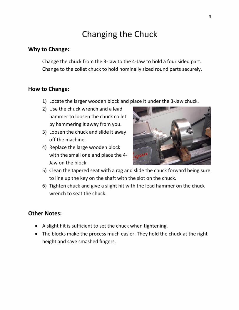
How to Change:
1) Locate the larger wooden block and place it under the 3-Jaw chuck.
2) Use the chuck wrench and a lead
hammer to loosen the chuck collet
by hammering it away from you.
3) Loosen the chuck and slide it away
off the machine.
4) Replace the large wooden block
with the small one and place the 4-
Jaw on the block.
5) Clean the tapered seat with a rag and slide the chuck forward being sure
to line up the key on the shaft with the slot on the chuck.
6) Tighten chuck and give a slight hit with the lead hammer on the chuck
wrench to seat the chuck.
Other Notes:
A slight hit is sufficient to set the chuck when tightening.
The blocks make the process much easier. They hold the chuck at the right
height and save smashed fingers.
4
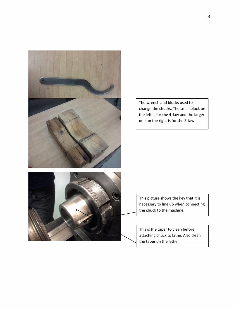
The wrench and blocks used to
change the chucks. The small block on
the left is for the 4-Jaw and the larger
one on the right is for the 3-Jaw.
This picture shows the key that it is
necessary to line up when connecting
the chuck to the machine.
This is the taper to clean before
attaching chuck to lathe. Also clean
the taper on the lathe.

5
Tools to Use Carbide vs. High strength steel
Carbide bits are what you will use for most of the cutting. They allow for a higher speed and will not dull as quickly. High strength steel bits will often give a better finish. Special bits will usually be made from HSS since it is much easier to grind and shape.
Left Handed Cutting Tool – The cutting edge is on the left side of the bit with clearances below the left cutting edge and the front. This bit is used for turning down outside diameters of parts. No cutting oil is necessary with this tool. The speed is determined by the chart in the shop.
Right Handed Cutting Tool – The cutting edge is on the right side of the bit with clearances below the right cutting edge and the front. This bit is used for facing and shortening parts. No cutting oil is necessary with this tool. The speed follows the chart.

6
Parting Tool – The parting tool is a piece of flat steel with clearance under the cutting edge. It is used to cut the part at the desired location. Cutting oil must be used or the part will bite. The speed is half of the chart speed.
Chamfer Tool/Two-Sided Cutter – The chamfer tool, usually cut at 90° is used to create chamfers at this angle. The bit can also cut in either direction.

7
Outside Threading Tool – As the name implies this tool is used to cut outer threads in a part.
This is usually done when you don’t have a big enough or a specific die to thread the part. This operation will be discussed in the Threading Section.
Boring Bar – This tool is used to bore holes into parts. It is easiest to drill a hole and use a small boring bar. From here you can work up to a larger boring bar. Do not use cutting oil and follow the chart for speed.
Inside Threading Tool – This tool is used to thread the inside of a part. As with the outside threads this is done when you don’t have a large enough tap or the correct size. This process will be discussed in the Threading Section.

8
Knurling Tool – This tool is used to put a knurl on a part. This improves the grip of the part. To knurl a part, touch up to the surface and dial in the X-direction .050 in and move the tool in the Z-direction for the desired knurl. Run the lathe at 100 rpms.
High strength steel is very useful in tool grinding. You can make tools to do many different operations. If
one of the basic tools doesn’t work for the desired operation you can take a HSS tool blank and shape a tool for the necessary application. Take the tool to the grinding wheel and use the knowledge you have gained on the lathe about tool clearances to create your tool.

9
Inside Threads
When to Use: Use the lathe to make inside threads when there isn’t a big enough tap or when creating a non-standard thread.
Why to Use: Inside threads can be made on a bored out part to allow for a threaded connection. Outside threads made have to be made on the corresponding part.
How to Use:
Cross Slide o Set at 60.5° for inside
threads. This dial is the one used for making cuts.
Dial on Cross Slide o Dial in .005-.001” per cut.
The deeper the thread, the smaller the cut.
X-Diameter Dial o Set at 0 on the outside edge of the part so you know where to return
to after each cut.
Feed Chart/Lead Screw o Set gear box for desired thread pitch
Engagement Indicator o Indicator has a 1, 2, and two dashes. For even numbered threads, (8,
10, 12) engage on any dash. For odd numbered threads, (7, 15, 21) engage on opposite dashes.
Engagement Lever o The lead screw lever
should be in the middle position
o Pull the engagement lever for threading

10
General Rules: Run at a low speed around XXX rpm
Be sure to back out tip at end. This prevents it from taking a huge cut and ruining the threads. In other words, when you disengage the thread engagement lever, dial out on the X-diameter dial.
Other Notes: Use lots of cutting oil.
Turn the chuck only as fast as you feel comfortable cutting.
This the dial to use for threading.
Engage when the desired dash
mark is straight up.
When set up the cross slide will
look like this.

11
Outside Threads
When to Use: Use the lathe to make outside threads when there isn’t a big enough die or when creating non-standard parts.
Why to Use: Outside threads can be put on parts in the lathe to give a threaded connection. Many times you will also need to thread the inside of the corresponding piece.
How to Use:
Cross Slide o Set at 59.5° for inside
threads. This dial is the one used for making cuts.
Dial on Cross Slide o Dial in .005-.001” per cut.
The deeper the thread, the smaller the cut.
X-Diameter Dial o Set at 0 on the outside edge of the part so you know where to return
to after each cut.
Feed Chart/Lead Screw o Set gear box for desired thread pitch
Engagement Indicator o Indicator has a 1, 2, and two dashes. For even numbered threads, (8,
10, 12) engage on any dash. For odd numbered threads, (7, 15, 21) engage on opposite dashes.
Engagement Lever o The lead screw lever
should be in the middle position
o Pull the engagement lever for threading

12
General Rules: Run at a low speed around XXX rpm
Be sure to back out tip at end. This prevents it from taking a huge cut and ruining the threads. In other words, when you disengage the thread engagement lever, dial out on the X-diameter dial
Other Notes: Use lots of cutting oil.
Turn the chuck only as fast as you feel comfortable
This the dial to use for threading.
Engage when the desired dash
mark is straight up.
When set up the cross slide will
look like this.