integration of wifi and wimax services: bandwidth ... 2.5 and 3g cellular networks combined with...
TRANSCRIPT

International Journal Web Applications Volume 7 Number 3 September 2015 95
ABSTRACT: The integration of WiFi and WiMAX will allow seamless connection between users from both systems with agreater capacity, higher bit rates and mobility access. To enable interoperability between WiFi and WiMAX a specialgateway is required known as WiFi/WiMAX router. In this paper, we investigate, through the use of OPNET simulationtools, number of WiFi users or hotspots could accommodated by a WiFi/WiMAX router and a WiMAX Base Station. Further,we evaluate the use of suitable applications and network traffic combinations for all WiFi users in order to fully optimizethe network within a constrained bandwidth. On top of that, subsequently to investigate more about the hybrid network,the quantity of nodes is supported to 200 users based on the same situation. This type of integration will solves many of thedifficulties in last-mile implementations, which also will benefit both users and service providers.
Keywords: Integration, Optimized, WiFi, WiMAX
Received: 1 June 2015, Revised 3 July 2015, Accepted 9 July 2015
© 2015 DLINE. All Rights Reserved
1. Introduction
The integration of WiFi-WiMAX as one of the architecture’s aims for the next generation of wireless networks has becomeincreasingly conventional especially in urban areas. The main purpose of such connectivity is to provide users with a varietyof applications with higher speed, larger coverage and mobility access. Although several studies have shown the integrationof 2.5 and 3G cellular networks combined with WLAN (Wireless Local Area Network), they do not provide Internet connectionssame as the broadband speeds which is offered by WiMAX (Worldwide Interoperability for Microwave Access)[1]. Thearrival of WiMAX technology has met the user’s demand for broadband wireless access since its’ ability to provide higherspeed connection, with a large area coverage alongside with the quality of service assurance [2].
WiFi (wireless fidelity) which also used generally as a synonym for WLAN has a variable data rate depending on thestandard, however, mainly the coverage area starts with a minimum of 20 meters up to maximum 100 meters. In order to extendthe coverage, the WLANs need to integrate with WMANs technology as the backhaul or a last mile solution[3].Thecoverage areas of WiMAX cover up to 50km and data rate up to 70 Mbps which is likely suitable apply in a metropolitan areaby connecting houses, buildings or cities [4].
Integration of WiFi and WiMAX Services: Bandwidth Optimization and TrafficCombination
Juwita Mohd Sultan, Garik Markarian, Phillip BenachourInfoLab21, School of Computing and CommunicationsLancaster University, Lancashire, United Kingdomj.mohdsultan,g.markarian,[email protected]
96 International Journal Web Applications Volume 7 Number 3 September 2015
The most practical options for internet access in metropolitan networks are WiFi and WiMAX [5]. Currently, there are anumber of cities in the world known as “wireless cities” such as Taiwan that could provide the people’s to access the wirelessinternet throughout their entire metropolitan areas [6]. In connection with that, integrating WiFi and WiMAX is the mostsuitable way to deploy large-scale wireless networks. Besides of the coverage extension, the amount of needed bandwidthis also another issue. The reason is as network applications become greater, bandwidth becomes critical to network efficiency[7].However, with the WiFi-WiMAX integration, multiple applications can be supported, especially voice and videocommunications.
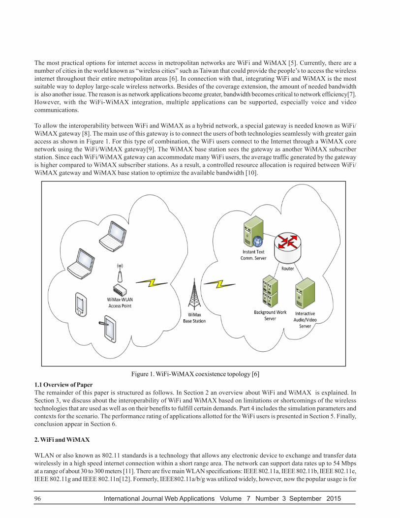
To allow the interoperability between WiFi and WiMAX as a hybrid network, a special gateway is needed known as WiFi/WiMAX gateway [8]. The main use of this gateway is to connect the users of both technologies seamlessly with greater gainaccess as shown in Figure 1. For this type of combination, the WiFi users connect to the Internet through a WiMAX corenetwork using the WiFi/WiMAX gateway[9]. The WiMAX base station sees the gateway as another WiMAX subscriberstation. Since each WiFi/WiMAX gateway can accommodate many WiFi users, the average traffic generated by the gatewayis higher compared to WiMAX subscriber stations. As a result, a controlled resource allocation is required between WiFi/WiMAX gateway and WiMAX base station to optimize the available bandwidth [10].
Figure 1. WiFi-WiMAX coexistence topology [6]
1.1 Overview of PaperThe remainder of this paper is structured as follows. In Section 2 an overview about WiFi and WiMAX is explained. InSection 3, we discuss about the interoperability of WiFi and WiMAX based on limitations or shortcomings of the wirelesstechnologies that are used as well as on their benefits to fulfill certain demands. Part 4 includes the simulation parameters andcontexts for the scenario. The performance rating of applications allotted for the WiFi users is presented in Section 5. Finally,conclusion appear in Section 6.
2. WiFi and WiMAX
WLAN or also known as 802.11 standards is a technology that allows any electronic device to exchange and transfer datawirelessly in a high speed internet connection within a short range area. The network can support data rates up to 54 Mbpsat a range of about 30 to 300 meters [11]. There are five main WLAN specifications: IEEE 802.11a, IEEE 802.11b, IEEE 802.11e,IEEE 802.11g and IEEE 802.11n[12]. Formerly, IEEE802.11a/b/g was utilized widely, however, now the popular usage is for

International Journal Web Applications Volume 7 Number 3 September 2015 97
802.11n standard that operates in the 2.4GHz and 5GHz bands [13]. WiMAX is designed for a long range communicationwhich created by the companies Intel and Alvarion in 2002 and ratified by the IEEE (Institute of Electrical and ElectronicsEngineers) under the name IEEE-802.16 [14] [15].
3. Integration of WiFi and WiMAX
WiFi is an implementation of wireless local area network within a short range area such as an office, a college or a universitycampus. WiMAX on the other hand covers a metropolitan area by connecting houses, buildings or cities. WiMAX isdifferent from WiFi in many respects; coverage distances, and data rate[16]. One of the main reasons why WiFi unable tooperate at greater distances as WiMAX is that radios operating in the unlicensed frequencies are not allowed to be aspowerful as those operated with licenses [17]. Since the power is less, the same effects happen to the distance.
Secondly, the WiFi MAC layer uses contention access, whereas WiMAX uses a scheduling algorithm. Using a contentionmode algorithm, users have to compete for data throughput to the access point[18]. In the meantime, by scheduling modealgorithm, it allows the user to only compete once to the access point. As the result, WiMAX outstrip WiFi in terms ofthroughput, latency, and spectral efficiency [19].
Both WiFi and WiMAX standards are designed for the Internet protocol applications. However, by combining these twotechnologies, WiMAX can be functioning as a backhaul while WiFi connected directly to the subscriber [20]. The mostinteresting part is network providers are able to deploy wireless broadband connections to areas not currently served in ashort time and cost-effectively since only little or no disruption to existing infrastructures is needed. On top of that bycombining WiFi and WiMAX technologies, a more complete suite of broadband services can be offered by service providers.It is because Wi-Fi is known for its high speed connectivity meanwhile high speed and large range connectivity for WiMAX[21].
Although, both the technology the WiMAX and the WiFi provide a wireless connection to last mile problem, their workingmechanism is technically different [22]. One of the primary reasons why WiFi unable to work at greater distances as WiMAXis that radios operating in the unlicensed frequencies are not admitted to be equally potent as those operated with licenses[23]. Since the power is less, the same effects happen to the distance. Secondly, the Wi-Fi MAC layer uses contention access,whereas WiMAX uses a scheduling algorithm. Using a contention mode algorithm, users have to compete for data throughputto the access level. In the interim, by scheduling mode algorithm, it lets the user to only compete once to the access level. Asthe result, WiMAX outstrip WiFi in terms of throughput, latency, and spectral efficiency [24].
4. Simulation Environment
For our system model, we proposed a number of WiFi users that can accommodate a WiMAX base station. On top of that wealso proposed the traffic combinations that can fully utilize for the same topology before another base station is needed inthe network.
The model consists of 40 WiFi users connected to 1 Base Station through a special access point (AP) namely as WiFi/WiMAX router. For this type of router, the WiMAX interface is used for communicating with the BS, and WiFi interface forcommunicating with WLAN stations. This router will convert the WiMAX packets to WiFi packets and route them to theWiFi clients. It also works as WiMAX clients which contain of a number of WiFi nodes. In terms of coverage, since the rangeof WiFi users is much smaller than WiMAX, this router will act as a link for WiFi users to reach the WiMAX BS. Therefore,in each location the service provider has installed a WiFi/WiMAX router or Customer Premises Equipment (CPE) to establishwireless connectivity from the customer site to the service provider’s network.The WiFi clients are placed in circular fashionwhich surrounds their respective AP or router. The traffic from WiFi/WiMAX router from WiFi hotspots are referred to asWiFi traffic.
We evaluate the idea of planning about the network using a network simulator tool; OPNET Modeler [25] [26]. The OPNETModeler enables users to create customized models and to simulate various communication networks [27]. It supportsfriendly graphical user interfaces to capture the specifications of deployed networks, equipment, and protocols. The trafficsassign in the network are VoIP (Voice over IP), video conferencing, HTTP browsing and file transfer. The simulation topologyis shown in Fig.2 meanwhile the parameters used for WiMAX and WLAN described in Table 1 and Table 2 respectively.

98 International Journal Web Applications Volume 7 Number 3 September 2015
Figure 2. Simulation Topology
Operating Frequency 2.5 GHz
Bandwidth 10 MHz, 1024 (subcarrier)
Maximum Transmission Power 0.5 to 3 W
Antenna Gain 15 to 18 dBi
Receiver Sensitivity -200 dBm
Min Reserved Traffic Rate (rtPS) 140 kbps
Max Sustained Reserve Traffic Rate (rtPS) 50 Mbps
Table 2. WiFi Simulation Parameters
Table 1. WiMAX Simulation Parameters
Data Rate 54 Mbps
Maximum Transmission Power 0.05 to 0.04 W
Buffer Size (bits) 265 000
Packet Reception Power Threshold -95 dBm
AP beacon Interval 0.02 sec

International Journal Web Applications Volume 7 Number 3 September 2015 99
5. Results and Discussion
The simulation runs for 10 minutes (600 seconds) and for the purpose of results analysis, a throughput, delay and packetdropped graph will be used. The throughput graph will determine the total data traffic successfully received and forwardedto the higher layer by the WiMAX MAC for WiMAX and WLAN MAC for WLAN connection. On top of that a packetdropped graph for WiMAX is to determine the higher layer data traffic dropped in bits/sec by the WiMAX MAC due to databuffer overflow. Meanwhile packet dropped in WLAN is due to full higher layer data buffer or the size of the higher layerpacket, which is greater than the maximum allowed data size defined in the IEEE 802.11 standard.
We conduct several simulation scenarios to evaluate the proposed algorithm. The first scenario evaluates the number ofWiFiusers that be accommodated for a single base station. The second scenario evaluates the optimized traffic that be generatedbased on the same topology[28].The last scenario investigate the network performance when the number of WiFi usersincrease to 200.
5.1Scenario 1In this scenario, there are 20 WiFi users on each CPE that connects to a WiMAX Base Station. To optimize the network, weadd another CPE that connects to another 20 WiFi users. For this scenario, we investigate the maximum number of WiFi usersor hotspots that can accommodate a single WiMAX Base Station. We begin with a minuscule number of users and measurethe network operation to recover out the restrictions. Since our primary aim is to make sure that each user will acquire therequested data rate, thus the most important parameter is this scenario is throughput.
Some observations we made are as follows: In Fig. 3 and 4, the throughput of WLAN and WiMAX produced almost the sameresult measured on either side of WiMAX-WiFi AP.
Figure 3. Throughput for WiMAX link(bits/sec)Based on Figure 3, throughput measured at CPE 1 and CPE 3 for a WiMAX link which is between the CPEs and Base Stationis ranged between 2 Mbit/s and 2.8 Mbit/s.
On the other side, throughput measured at CPE 1 and CPE 3 for a WLAN link which is between the CPEs and WiFi users isstabilized at 2 Mbit/s as shown in Figure 4.

100 International Journal Web Applications Volume 7 Number 3 September 2015
Figure 4. Throughput for WiFi link (bits/sec)
In comparison, that there is not much throughput differentiation for both link which shows that traffic requested by WiFiusers are mostly successful received. Next to examine deeply on the differentiation, we measured the packet dropped for bothconnections.
Further, as depicted in Figure 5, it shows that, there are some packet dropped and lost occurred in WLAN link. However ithappened due to data buffer overflow. The buffer acts as a temporary memory to keep data for a while time have several sizes.Nevertheless, to avoid the packet dropped, we tried to increase the buffer size, however it will also increase the delayperformance and therefore after a number of experiments, the suitable buffer size is chosen which will optimize the network.Opposite tothat, there is no loss of the WiMAX link as all the data is successfully transmitted and received.
Number of WiFi users Traffic combinations (application)
6 VoIP
1 Video Conferencing (Skype)
7 File Transfer Protocol
6 Web Browsing
Table 3. Traffic Combination for 20 WiFi Users

International Journal Web Applications Volume 7 Number 3 September 2015 101
Figure 5. Data dropped (buffer overflow) for WiFi link
5.2 Scenario 2In the second scenario, the optimized traffic that be generated based on the previous topology is evaluated. Since we haveevaluated the optimum WiFi user can accommodate in a single CPE, therefore in this scenario we investigate the effect on thetraffic/application assigned to the users. For this purpose, we include the WiFi users with multi-applications starting with theheavy traffics as voice and video communication and also the low bit rate traffics such as file transfer and web browsing.Therefore, in order to fully utilize the network, each WiFi users with their application is guaranteed with minimal or acceptablepacket loss. The proposed traffic for 20 WiFi users used in this scenario is described in Table 3.
Since voice is the most highly delay sensitive for real-time applications, the Mean Opinion Score (MOS) value and jitter areinvestigated in this scenario as illustrated in Fig. 6 and Fig. 7 respectively. MOS is the measurement of the quality of humanspeech at the end of the destination. Besides dictating the quality in voice and video communication, whether it is a goodor bad experience, MOS gives a numerical indication of the perceived quality of the media received after being sent andeventually compressed using codecs. MOS is expressed in one number, from 1 to 5, 1 being the worst and 5 the best. Thedetails of MOS number are as follows: 5-Perfect. Like face-to-face conversation or radio reception, 4-Fair. Imperfections canbe perceived, but the sound still clear, 3–Annoying, 2-Very annoying and nearly impossible to communicate, 1- Impossibleto communicate.
Figure 6 shows the MOS value for all the WiFi users with a VOIP application which is ranged between 3.85 to 4.05 and basedon the MOS table [29], it is defined as good and excellent in quality.
Another important implication of this investigation is the jitter value as described in Fig. 7, which shows zero reading. Jitteris defined as the time difference in packet inter-arrival time to their destination. In VOIP communication, for example, when aframe is sent every 10 ms, some of the packets can immobilize somewhere in between inside the packet network and not arriveat expected regular peace to the destined station. This is because one of the packets encounters some delay on its path and

102 International Journal Web Applications Volume 7 Number 3 September 2015
it is received little later than it was seized. The problem encounters to jitter and also mitigate to packet delay. Therefore, forVOIP, it is important the system to experienced zero jitter to have a successful communication network.
Figure 6. MOS value for WiFi users with VoIP application
Figure 7. Average jitter for WiFi users with VoIP application

International Journal Web Applications Volume 7 Number 3 September 2015 103
5.3Scenario 3
The third scenario settings is the same as in the previous, however the quantity of users is expanded to 200. In this scenario,there are 5 CPEs which each CPE comprises of 20 WiFi users. The covered area is 500m x 500m allowing for simple placementof the WiMAX CPE and WiFi users and providing minimal drop in data rates or potential interference. The CPE is place a fewhundred meters from the base station around the area or central site area. Each device acts as a WiFi AP (Access Point) witha bridged connection to the closest WiMAX base station. The WiFi coverage is aimed at the main area as the effective rangeis limited to a 2m to 60m radius dependent on obstacles and RF interference from other terminals or devices and wirelessequipment. The technical configuration for each WiMAX base station, WiFi/WiMAX router and WiFi user in the simulationis shown in the table IV, V, VI respectively;
Operating Frequency 2.5 GHz
Bandwidth 10 MHz, 1024 (subcarrier)
Transmitter Power 2 W
Antenna Gain 18 dBi
WLAN Standard HT PHY 5.0GHz (802.11n)
Data rate 6.5Mbps to 60Mbps
Antenna Gain 18 dBi
Modulation OFDM
Max TX Power 3W
Standard
Data rate 6.5Mbps to 60Mbps
Antenna Gain 18 dBi
Modulation OFDM
Max TX Power 40mW
Buffer size 32 000Bytes
Table 4. WiMAX Base Station
Table 5. WiFi/WiMAX router (CPE)
Figure 8 indicates throughput of WiMAX links for all 5CPEs declined, which is contrasted as in Figure 3. Previously thethroughput for all CPEs are is higher than 2.2 Mbps while now it has dropped to the most minimal of 1.3 Mbps. This is becausesince more users are sharing the same bandwidth in the same channel. Further on, we explore the throughput for WiFi link asrepresented in Figure 9.
Table 6. WiFi User

104 International Journal Web Applications Volume 7 Number 3 September 2015
Figure 8. Throughput for WiMAX link(bits/sec)
Figure 9. Throughput for WiFi link (bits/sec)

International Journal Web Applications Volume 7 Number 3 September 2015 105
As notice before, since there are 200 users in the current scenario, the throughput for each WiFi user is relied upon to fallwhich is described in Fig. 9. Throughput of WiFi link at each CPE isbelow2 Mbps and even two’s of the CPE are low as 1.2Mbps. In view of throughput at WiMAX and WiFi link for each CPE at scenario1, the data rate gain for both links aredistinctive and it shows that there is packet dropped experienced in the channel. Along these, we examine this behavior bymeasuring the packet loss as depicted in Figure 10.
Figure 10. Data dropped (buffer overflow) for WiFi link
As shown in Fig.10, there is a large difference of data dropped for WiFi link compared to the results obtained in Scenario 1.This is due to the increase number of users which some of the WiFi users experienced lower throughput since the network arefully occupied.Another parameter than we quantified in this scenario is jitter. Since in the first scenario we measured jitter forVOIP users, therefore in this scenario, we investigate the same quality of jitter.
Since there are more than 20 users are appointed to VOIP application in this scenario, we only show users with the mostastounding average jitter as depicted in Fig.11. Comparing with the previous result, jitter increased from zero to 0.19 seconds.Since more users are added in this scenario, create a higher delay for each user and also increases the latency for bothsystems.
6. Results and Discussion
In this paper, a research has been explored on the cross system network optimization which involves WiFi and WiMAXparticularly in our scenario. The first part of the research covers the number of WiFi hot spots that could accommodate byone WiFi/WiMAX router or also known as CPE. In further, another set of WiFi hotspot and CPE is added to optimized a single

106 International Journal Web Applications Volume 7 Number 3 September 2015
WiMAX base station. The second part proposes the optimized traffic combinations for each WiFi user based on the firstscenario. The results are presented in the throughput, delay, packet dropped, MOS and also jitter graphs to evaluate theperformance of each scenario. The third part demonstrates the results as the quantity of users in the network is occupied fivetimes more than in the first scenario. Simulation results reveal that the throughput for WiFi users were slightly lower, datadropped was expanded to a certain value which likewise expanded the average jitter in the network.
6.1 Remaining WorkThe next stage of this work is the production of an integration of WLAN and LTE (Long Term Evolution) networ
Figure 11. Average jitter for WiFi users with VoIP application
References
[1] Ahmed, S., Sherif, W., Qusay, S. (2010). Dealing with quality of service in hybrid wired-wireless networks, In: Proceedings2nd Int. Conf. Netw. Appl. Protoc. Serv. NETAPPS 2010, 105–109.

International Journal Web Applications Volume 7 Number 3 September 2015 107
[2] Malik, G., Singh, A. (2013). International Journal of Advanced Research in Performance Evaluation of WiFi and WiMaxUsing Opnet, 3 (6) 571–579.
[3] Lin, H., Lin, Y., Chang, W., Cheng, R. (2009). An Integrated WiMAX / WiFi Architecture with QoS Consistency overBroadband Wireless Networks, System, 1–7.
[4] Sang, K., Wang, J. X., Modie. (2010). Seamless mobility for WiFi-WiMAX heterogeneous networks using SCTP and DNS,ICEIT 2010 - 2010 Int. Conf. Educ. Inf. Technol. Proc., 2, ICEIT, 385–389.
[5] Ghazisaidi, N., Kassaei, H., Bohlooli, M. S. (2009). Integration of WiFi and WiMAX-Mesh Networks, 2009 Second Int.Conf. Adv. Mesh Networks, 6–11.
[6] Song, S., Issac, B. (2014). Analysis of Wifi and Wimax and Wireless Network Coexistence, Int. J. Comput. NetworksCommun., 6 (6) 63–77.
[7] Doulatyari, E., Kohan, P. A., Esmailpour, A., Have, W. (2012). Quality of Service Support for a WiFi-WiMAX Network in aTest-bed Environment, 316–321.
[8] Andrews, N., Kondareddy, Y., Agrawal, P. (2010). Channel management in collocated WiFi-WiMAX networks, In:Proceedings Annu. Southeast. Symp. Syst. Theory, 133–137.
[9] Vijayalakshmy, G., Shivaradje, G. (2012). WiMAX and WiFi Convergence Architecture to Achieve QoS, 512–521, 2012.
[10] Hou, L., Miao, K. X. (2009). A pre-authentication architecture in WiFi WiMAX integrated system, Commun. Netw. China,2009. ChinaCOM 2009. Fourth Int. Conf., 1–5.
[11] Banerji, S., Chowdhury, R. S. (2013). Wi-Fi & WiMAX/ : A Comparative Study, 2.
[12] Zhu, H., Li, M. (2004). A survey of quality of service in IEEE 802.11 networks, IEEE Wirel. Commun., 11 (4) 6–14.
[13] Rivera Ibáñez, S., Aquino Santos, R., Rangel Licea, V., Block, A. E., García Ruiz, M. Á. (2008). Hybrid WiFi-WiMAXnetwork routing protocol, In: Proceedings - Electron. Robot. Automat. Mech. Conf. CERMA 2008, 87–92.
[14] Ammar, B. A., Mohd, D. B., Muhammad, I. (2012). IEEE 802.21 based vertical handover in WiFi and WiMAX networks,2012 IEEE Symp. Comput. Informatics, Isc. 140–144.
[15] Samhat, A. E., Abdi, M. (2007). Security and AAA architecture for WiFi-WiMAX mesh network,network environment.
In: Proceedings 4th IEEE Internatilonal Symp. Wirel. Commun. Syst. 2007, ISWCS, 587–591.
[16] Adhicandra, I. ( 2009). Configuration of WiMAX Networks supporting Data and VoIP Traffic, 1–5.
[17] Doulatyari, E., Kohan, P. A., Esmailpour, A., Have, W. (2012). Quality of Service Support for a WiFi-WiMAX Network ina Test-bed Environment, 316–321.
[18] Park, E. C. (2009). Efficient uplink bandwidth request with delay regulation for real-time service in mobile wimax networks,IEEE Trans. Mob. Comput., 8 (9) 1235–1249.
[19] Sarma, A., Chakraborty, S., Nandi, S. (2015). Deciding Handover Points based on Context Aware Load Balancing in aWiFi-WiMAX Heterogeneous Network Environment, IEEE Trans. Veh. Technol., 9545, 1–1, 2015.
[20] Niyato, D., Hossain, E. (2007). Integration of WiMAX and WiFi/ : IEEE Commun. Mag., May, 140–146.
[21] Wang, W., Liu, X., Vicente, J., Mohapatra, P. (2011). Integration gain of heterogeneous WiFi/WiMAX networks, IEEETrans. Mob. Comput.,10 (8) 1131–1143.
[22] Hou, L., Miao, K. X. (2009). A pre-authentication architecture in WiFi WiMAX integrated system, Commun. Netw. China,2009. ChinaCOM 2009. Fourth Int. Conf., 1–5.
[23] Doulatyari, E., Kohan, P. A., Esmailpour, A., Have, W. (2012). Quality of Service Support for a WiFi-WiMAX Network ina Test-bed Environment, 316–321.
[24] Sarma, A., Chakraborty, S., Nandi, S. (2015). Deciding Handover Points based on Context Aware Load Balancing in aWiFi-WiMAX Heterogeneous Network Environment, IEEE Trans. Veh. Technol., 9545, 1–1.
[25] Sultan, J. M., Markarian, G., Benachour, P. (2014). WiMAX Quality of Service Deployment in Disaster Management,International Conf. On Advances in Computing, Communication and Information Technology, CCIT 2014.

108 International Journal Web Applications Volume 7 Number 3 September 2015
[26] Zvikhachevskiy, D., Sultan, J. M., Dimyati, K. (2013). Quality of Service Mapping Over WiFi+WiMAX and WiFi+LTENetworks, Journal of Telecommunication Electronic and Computer Engineering (JTEC), 5 (2).
[27] Garg, N. (2014). Analysis of Black Hole Attack using Different Routing Protocols on WLAN-WiMAX Interface Network,International Journal of Advanced Research in Computer Science and Software Engineering Performance 4 (8) 1029–1038.
[28] Sultan, J. M., Markarian, G., Benachour, P. (2014). WiMAX Quality of Service Deployment in Disaster Management, 5 (1)36–40.
[29] Mean opinion score - Wikipedia, the free encyclopedia.