drylin n low profile linear guide system - autoflexible n.pdfdrylin® n low profile linear guide...
TRANSCRIPT

DryLin® N Low ProfileLinear Guide System
• Low profile height and width
• Replaceable polymer sliding elements
• Anodized aluminum rail
• High speed and acceleration possible
• Lubricant-free
• Lightweight

Properties
Features
• Good for tight designconstraints
• Replaceable glide pads• Excellent for low loads• Excellent corrosion resistance
• Through hole for flexiblemounting
• Extremely low friction/low wear• Replaceable glide pads• Low weight• Flexible size• Excellent for low to medium
loads
DryLin® NSelectionGuide
Maximum Load
Maximum Speed
Maximum Rail Length
Carriage Weight
Rail Weight
Rail Material
Temperature
11 lbs (50 N)
49 fps (15 m/s)
72 in. (1828 mm)
.0602 lbs (1.7 g)
1.6 oz/ft (150 g/m)
Anodized Aluminum
-40 to 194°F
Available Available
110 lbs (500 N)
49 fps (15 m/s)
11.5 ft (3500 mm)
.38 oz - .44 oz (10.8g - 12.5g)
3.01 oz/ft (290 g/m)
Anodized Aluminum
-40 to 194°F
Brass / iglide® J Chromated Zinc / iglide® J
Preloaded for reduced clearance
Carriage Material
� 6mm
17 mm
� 9.5mm
27 mm
DryLin® N27-01DryLin® N17
Online LifetimeCalculationwww.igus.com

• Flexible size• Replaceable glide pads• Excellent for medium to high
loads• Wide base for stable design
• May use one rail instead of twonarrow rails
• High accelerations possible• Replaceable glide pads• Extremely low friction/low wear • Good for higher loads• Aluminum carriage available for
low weight/higher loads
Not Available Not Available
154 lbs (700 N)
49 fps (15 m/s)
11.50 ft (3500 mm)
.066 lbs (30 g)
.025 lbs/inch (450 g/m)
Anodized Aluminum
-40 to 194°F
220 lbs (50 N)
49 fps (15 m/s)
11.50 ft (3500 mm)
.22 lbs (100 g)
.064 lbs/inch (1140 g/m)
Anodized Aluminum
Chromated Zinc / iglide® J Chromated Zinc / iglide® JAluminum available
-40 to 194°F
� 9.5mm � 12mm
40 mm 80 mm
• Threaded adjusting studsfor easy attachment
• Flexible size• Replaceable glide pads• Extremely low friction/low
wear • Excellent for low to
medium loads
Available
110 lbs (500 N)
49 fps (15 m/s)
11.50 ft (3500 mm)
.027 lbs (12.5 g)
.016 lbs/inch (290 g/m)
Anodized Aluminum
-40 to 194°F
Chromated Zinc / iglide® J
� 9.5mm
27 mm
DryLin® N27-02 DryLin® N40 DryLin® N80

Inte
rnet
: h
ttp
://w
ww
.igu
s.co
mE
-Mai
l: sa
les@
igu
s.co
mQ
uic
kSp
ec:
ww
w.ig
us.
com
/qs/
Dry
Lin
.asp
Tele
ph
on
e1-
888-
803-
1895
Fax
1-
401-
438-
7680
Dry
Lin
®N
L
inea
r G
uid
e S
yste
m
21.4
DryLin® N Low Profile Linear Guide Systems
The DryLin® N series offers extremely low profiles in several widths, and is therefore ideal in tight spaceconstraints. Like all DryLin® products the carriages are designed to glide smoothly on anodized alu-minum rails without the need for messy lubricants. They are also available in preloaded versions forreduced running clearance. DryLin® N is a particularly low-cost alternative to miniature ball bearingsystems, and is more precise and economical when compared to many custom-machined or simpleplastic parts.
� Small mounting height and width
� Maintenance-free and self-lubricating
� High resistance to dirt
� Corrosion-resistant
� Low wear and low coefficient of friction
� Lightweight due to aluminum polymer combination
� Very high speed and acceleration possible
� Replaceable polymer sliding elements made of iglide® J
� Base structure of the carriage made of plastic (size 17)or zinc, chromated (size 27, 40 and 80)
� Anodized aluminum rails
� Available from stock
Anodized aluminum rails
iglide® J plain bearing liner
Zinc chromated carriage Type 01
(with mounting hole)
Zinc chromed carriage Type 02
(with thread)
Advantages of DryLin® N
+194°F (+90ºC)
-40°F (-40ºC)
DryLin® N Height
N17 .24 in (6.0 mm)
N27 .37 in (9.5 mm)
N40 .37 in (9.5 mm)
N80 .47 in (12.0 mm)
DryLin® N80, black ano-dized used for adjustingspot lights
DryLin® N40 in a closed-loop drive conveyor
DryLin® N80 in a belt- drivenlinear ac tua tor for high-speed handling up to 12 m/s
Technical DataSliding elements:
Maintenance-free
Material:
iglide® J*
Max. surface speed:
50 fps (15 m/s)
Temperature range:
-40°F to +194°F
(-40 °C to +90 °C)
* Other materials upon request
17 mm 40 mm 80 mm27 mm
Online LifetimeCalculationwww.igus.com
Dry
Lin
®N
L
inea
r G
uid
eS
yste
m
21.5
DryLin® N Low Profile Linear Guide Systems
PD
F:
ww
w.ig
us.
com
/pd
f/D
ryL
in.a
spS
pec
s/C
AD
/RF
Q:
ww
w.ig
us.
com
/Dry
Lin
N.a
spR
oH
S in
fo:
ww
w.ig
us.
com
/Ro
HS
.asp
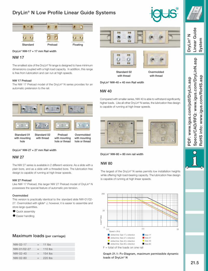
Maximum loads (per carriage)
NW-02-17 = 11 lbs
NW-01/02-27 = 110 lbs
NW-02-40 = 154 lbs
NW-02-80 = 220 lbs
0.3 332
20
200
dotted line: Size 17 z-direction
dotted line: Size 27 z-direction
dotted line: Size 40 z-direction
dotted line: Size 80 z-direction
Size 17 z-direction
Size 27 z-direction
Size 40 z-direction
Size 80 z-direction
Speed v (ft/s)
Load
F (l
bs)
3.5
F = total of the loads on one rail
Graph 21.1: Fv-Diagram, maximum permissible dynamicloads of DryLin® N
Preloadwith mountinghole or thread
Overmoldedwith mountinghole or thread
Standard 02with thread
Standard 01with mounting
hole
DryLin® NW-17 = 17 mm Rail width
DryLin® NW-40 = 40 mm Rail width
DryLin® NW-80 = 80 mm rail widthDryLin® NW-27 = 27 mm Rail width
Standard 02 with thread
Overmoldedwith thread
Preload FloatingStandard
NW 80
The largest of the DryLin® N series permits low installation heightswhile offering high load-bearing capacity. The lubrication free designis capable of running at high linear speeds.
NW 40
Compared with smaller series, NW 40 is able to withstand significantlyhigher loads. Like all other DryLin® N series, the lubrication free designis capable of running at high linear speeds.
NW 27
The NW 27 series is available in 2 different versions: As a slide with aplain bore, and as a slide with a threaded bore. The lubrication freedesign is capable of running at high linear speeds.
NW 27 PreloadLike NW 17 Preload, this larger NW 27 Preload model of DryLin® Npossesses the special feature of automatic pre-tension.
OvermoldedThis version is practically identical to the standard slide NW-01/02-27. Overmolded with iglide® J, however, it is easier to assemble andstore large quantities.
Quick assembly
Easier handling
NW 17
The smallest size of the DryLin® N range is designed to have minimumdimensions coupled with a high load capacity. In addition, this rangeis free from lubrication and can run at high speeds.
NW 17 PreloadThe NW 17 Preload model of the DryLin® N series provides for anautomatic pretension to the rail.

When using systems with 2 parallel rails, one side must be designated as the “fixed” rail, and the opposite side the “floating” rail.
Why use floating bearings?• promotes smooth gliding performance and maximizes bearing life• prevents binding caused by parallelism and angle errors• decreases necessary drive force and wear by minimizing friction-forces• Enhances the precision of the system over the bearings’ lifetime.• Reduce assembly time and cost
Fixed BearingsThe “fixed” bearing rail should be positioned closest tothe drive force. This rail will determine the precision ofthe system; no system should contain more than two“fixed” bearings.
Floating/Self-Aligning BearingsThe “floating” rail should be the rail located furthest fromthe drive force. It is to act only as a guide, and willcompensate for any misalignments or angle errors in thesystem ensuring proper functionality.
Mounting SurfacesThe mounting surfaces for rails and bearings should havea very flat surface (e.g milled surface) in order to enhanceperformance. Variations in these surfaces may becompensated for by using floating bearings.
Inte
rnet
: h
ttp
://w
ww
.igu
s.co
mE
-Mai
l: sa
les@
igu
s.co
mQ
uic
kSp
ec:
ww
w.ig
us.
com
/qs/
Dry
Lin
.asp
Tele
ph
on
e1-
888-
803-
1895
Fax
1-
401-
438-
7680
Dry
Lin
®N
L
inea
r G
uid
e S
yste
m
21.6
DryLin® N Low Profile Linear Guide Systems
Fixed and Floating Bearing Mounting Instructions
Eccentric Forces
2:1 Rule =
permissible distances
of the applied forces
Online LifetimeCalculationwww.igus.com
The 2 :1 RuleWhen using linear plain bearings it is important to ensure that the acting forcesfollow the 2:1 Rule (see drawing). If either the load or the drive force (F) isgreater than twice the bearing length (1X), then a binding or interrupted motionmay occur.If the location of the drive force or load cannot be changed, simply increasethe distance between the bearings, or create a counterbalance to move thecenter-of-gravity back within the 2 to 1 ratio.
Standard Version
Maximum float = ± .02” (.5 mm)
Horizontal Float “LLZ”
Vertical Float “LLY”
DryLin® N - Floating Systems
Part No.Fixed Bearing - CARRIAGE ONLY
NW-02-17
NW-02-27 / NW-02-27
NW-02-40
NW-02-80
Part No.Horizontal Floating - CARRIAGE ONLY
NW-02-17 LLZ
NW-01-27 LLZ
NW-02-27 LLZ
NW-02-40 LLZ
NW-02-80 LLZ
Part No.Vertical Floating - CARRIAGE ONLY
NW-02-17 LLY
NW-01-27 LLY
NW-02-27 LLY
NW-02-40 LLY
NW-02-80 LLY
Vertical Float “LLYZ”
Part No.Horizontal/Vertical Floating - CARRIAGE ONLY
NW-02-17 LLYZ
NW-01-27 LLYZ
NW-02-27 LLYZ
NW-02-40 LLYZ
NW-02-80 LLYZ
Automatic compensation ofparallelism errors
Floating Fixed

Dry
Lin
®N
L
inea
r G
uid
eS
yste
m
21.7
DryLin® N Low Profile Linear Guide Systems
PD
F:
ww
w.ig
us.
com
/pd
f/D
ryL
in.a
spS
pec
s/C
AD
/RF
Q:
ww
w.ig
us.
com
/Dry
Lin
N.a
spR
oH
S in
fo:
ww
w.ig
us.
com
/Ro
HS
.asp
Part No. for single carriages:
NW-02-17 Size 17 with thread
NW-02-17P Size 17 with pre-tension
NW-01-27 Size 27 with mounting hole
NW-01-27P Size 27 with pre-tension
NW-02-27 Size 27 with thread
NW-02-27P Size 27 with pre-tension
NW-11-27 Size 27 with mounting hole, overmolded
NW-12-27 Size 27 with thread, overmolded
NW-02-40 Size 40 with thread
NW-12-40 Size 40 with thread, overmolded
NW-02-80 Size 80 with thread
NW-12-80 Size 80 with thread, overmolded
Part No. for single rails:
NS-01-17, length (mm) Width of rail 17 mm
NS-01-27, length (mm) Width of rail 27 mm
NS-01-40, length (mm) Width of rail 40 mm
NS-01-80, length (mm) Width of rail 80 mm
DryLin® N for in a closed loop conveyor
NK -02-02 -27 -500 LLZ C5=20
Structure of the Part No. for assembled systems:
Assembled system
Type of carriage01 with thru bore02 with thread11 with thru bore, overmolded, size 2712 with thread, overmolded, size 27, 40
Size17/27/40/80
No. of carriages
Length of rail in mm
Carriage optionsLeave blank: StandardLLZ: Floating z-directionLLY: Floating y-directionLLYZ: Floating y- and z-directionP: Preload (max. 1 N), only sizes 17/27
Rail optionsLeave blank: Standard with holesNo holes: Without holesC5 = ... mm If hole spacing is not symmetrical

Structure of the Part No. – Standard version
Length of rail (mm)Number of carriages“P” for preloadedSizeThreadComplete system
Inte
rnet
: h
ttp
://w
ww
.igu
s.co
mE
-Mai
l: sa
les@
igu
s.co
mQ
uic
kSp
ec:
ww
w.ig
us.
com
/qs/
Dry
Lin
.asp
Tele
ph
on
e1-
888-
803-
1895
Fax
1-
401-
438-
7680
Dry
Lin
®N
L
inea
r G
uid
e S
yste
m
21.8
DryLin® N Low Profile Linear Guide Systems - NK-02-17
S =
min
. 21
6 ±0
,3
Dep
th fo
r sc
rew
tigh
teni
ngm
ax. s
+ 2
.5m
in.
s +
0.5
for Machine Screws M3DIN 7984/DIN 6912/DIN 84EN ISO 1707
9.6
Hole min. ø 5
M3
17 -0,40
C5 =20...49mm 14
20
60C6 =20...49mm
max. 1960
11 lbs
ly = 1700 mm4
Wb = 200 mm3
Mx = .44 lbf · ft
11 lbs lz = 120 mm4
Wb = 33 mm3
My = .13 lbf · ft
Mz = .13 lbf · ft
y
x
z
Static load-bearing capacity andgeometric moment of inertia
All dimensions are in (mm) unlessotherwise specified
Dimensions in mm
CAD files online: www.igus.comTesting and sorting machines
Carriages with mounting nuts
Data:Part No. carriage NW-02-17(P)Part No. rail NS-01-17Rail weight 1.61 oz/ft (150 g/m)Carriage weight .06 oz.(1.7 g)Max. rail length(1) 72 in (1828 mm)Standard bore pattern symmetrical (C5=C6)Preload available YesMax. static load 11 lbs.(1)4000 mm rail available upon request
NK -02 -17 -2P -500

Dry
Lin
®N
L
inea
r G
uid
eS
yste
m
21.9
DryLin® N Low Profile Linear Guide SystemsNK-01-27 / NK-02-27
PD
F:
ww
w.ig
us.
com
/pd
f/D
ryL
in.a
spS
pec
s/C
AD
/RF
Q:
ww
w.ig
us.
com
/Dry
Lin
N.a
spR
oH
S in
fo:
ww
w.ig
us.
com
/Ro
HS
.aspDimensions in (mm) unless otherwise specified
CAD files online: www.igus.com
Version 01: Carriages with thru hole Version 02: Carriages with threaded boss
Data:Part No. carriage NW-02-27(P)Part No. rail NS-01-27Rail weight 3.01 oz. (290 g/m)Carriage weight .44 oz. (12.5 g)Max. rail length 140 in (3560 mm)Standard bore pattern symmetrical (C5=C6)Preload available Yesfor reduced clearance .22 lbs (1N)
Data:Part No. carriage NW-01-27(P)Part No. rail NS-01-27Rail weight 3.01 oz. (290 g/m)Carriage weight .38 oz. (10.8 g)Max. rail length 140 in (3560 mm)Standard bore pattern symmetrical (C5=C6)Preload available Yesfor reduced clearance .22 lbs (1N)
C5 =20-49mm 20
30
40
60
C5 =20-49mm 20
30
40
60
Static load-bearing capacity and geometricmoment of inertia
* Length of overmolded carriages version NW-11-27 and NW-12-27: 34 ± 0.7 mm
NK-01-27 NK-02-27
22 0-0.4
9.5
0.4
-0.4
3
1.5
14
27
0.8
1.5
1.5
for Machine Screws M4DIN 7984 / DIN 6912DIN 84 / EN ISO 1707
Hole min. Ø 6.5
s =
min
. 5
M4 max. torque .88 lbf · ft (1.2 Nm)
min
. s
- 1
max
. s +
4.5
Scr
ew le
ngth
112 lbs
ly = 6524 mm4
Mx = 3.7 lbf · ft
112 lbs lz = 588 mm4
My = 1.84 lbf · ft
Mz = 1.84 lbf · ft
112 lbs
ly = 6524 mm4
112 lbs lz = 588 mm4
Mx = 3.7 lbf · ft
My = 1.84 lbf · ft
Mz = 1.84 lbf · ft

Structure of the Part No. – Standard version
Length of rail (mm)Number of carriagesSizeThreadComplete system
Inte
rnet
: h
ttp
://w
ww
.igu
s.co
mE
-Mai
l: sa
les@
igu
s.co
mQ
uic
kSp
ec:
ww
w.ig
us.
com
/qs/
Dry
Lin
.asp
Tele
ph
on
e1-
888-
803-
1895
Fax
1-
401-
438-
7680
Dry
Lin
®N
L
inea
r G
uid
e S
yste
m
21.10
DryLin® N Low Profile Linear Guide Systems - NK-02-40
Data:Part No. carriage NW-02-40Part No. rail NS-01-40Rail weight 4.84 oz/ft (450 g/m)Carriage weight 1.06 oz. (30 g)Max. rail length(1) 140 in (3550 mm)Standard bore pattern symmetrical (C5=C6)(1)4000 mm rail available upon request
157 lbs
157 lbs
I = 970 mm4
Wb = 170 mm3
Mx = 12 lbf · ft
My = 4.4 lbf · ftMz = 4.4 lbf · ft
I = 26400 mm4
Wb = 660 mm3
Hole Min. Ø 6.5
40
1.4
9.5
0.8
s=m
in.5
23
For machine screws M4DIN 7984/DIN 6912/DIN 84EN ISO 1707 / EN ISO 7045
M4 - max. torque 11 lbf - in (1.2 Nm)
C5 = 20-49.5 mm (C5 = C6)
50
40
20
60
max. 3560
C5 = 20-49.5 mm (C5 = C6)
NK -02 -40 -2 -500
DryLin® NK – Complete system
Option:
Polymer End cap for rail,Part No. NSK-40
* Length of carriages overmolded version NW-12-40: 52 mm
Static load-bearing capacity and geometricmoment of inertia
CAD files online: www.igus.com
Dry
Lin
®N
L
inea
r G
uid
eS
yste
m
21.11
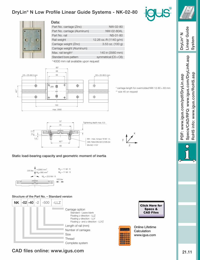
DryLin® N Low Profile Linear Guide Systems - NK-02-80
PD
F:
ww
w.ig
us.
com
/pd
f/D
ryL
in.a
spS
pec
s/C
AD
/RF
Q:
ww
w.ig
us.
com
/Dry
Lin
N.a
spR
oH
S in
fo:
ww
w.ig
us.
com
/Ro
HS
.asp
igus
56
68
80*
150
40**
M4
max. 3560
C5 = 25-99.5 mm C6 = 25-99.5 mm
DIN 7984/DIN 6912/DIN 8440**
1.6
80
12+
0.3
–0.
3
45
57Tightening depth max. 6.5
M4 - max. torque 18 lbf · in.
EN ISO 1707
225 lbs
I=2900 mmWb=380 mm
225 lbs4
3
Mx = 23.9 lbf · ft
My = 11 lbf · ft
Mz = 11 lbf · ft
y
x
z
* carriage length for overmolded NW-12-80 = 83 mm
** size 45 on request
-02 -40 -2 -500
Structure of the Part No. – Standard version
Carriage option Standard - Leave blankFloating z-direction - LLZFloating y-direction - LLYFloating y- and z-direction - LLYZ
Length of rail (mm)Number of carriagesSizeThreadComplete system
Static load-bearing capacity and geometric moment of inertia
Data:Part No. carriage (Zinc) NW-02-80Part No. carriage (Aluminum) NW-02-80ALPart No. rail NS-01-80Rail weight 12.26 oz./ft (1140 g/m)Carriage weight (Zinc) 3.53 oz. (100 g)Carriage weight (Aluminum)Max. rail length(!) 140 in (3560 mm)Standard bore pattern symmetrical (C5=C6)(1)4000 mm rail available upon request
CAD files online: www.igus.com
Online LifetimeCalculationwww.igus.com
-LLZNK