construction of irrigation schemes of irrigation schemes developed by ... engineer to assume the...
TRANSCRIPT

Irrigation ManualModule 13
Construction of Irrigation Schemes
Developed by
Andreas P. SAVVAand
Karen FRENKEN
Water Resources Development and Management Officers
FAO Sub-Regional Office for East and Southern Africa
In collaboration with
Lee TIRIVAMWE, National Irrigation Engineer, Zimbabwe
Victor MTHAMO, Irrigation Engineer Consultant
Simon MADYIWA, Irrigation Engineer Consultant
Harare, 2001

Irrigation manual
ii – Module 13
Module 13 – iii
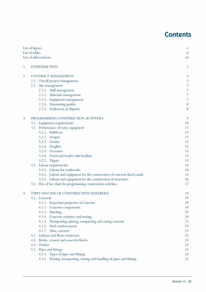
Contents
List of figures vList of tables viList of abbreviations vii
1. INTRODUCTION 1
2. CONTRACT MANAGEMENT 32.1. Overall project management 32.2. Site management 7
2.2.1. Staff management 72.2.2. Materials management 72.2.3. Equipment management 72.2.4. Maximizing profits 82.2.5. Settlement of disputes 8
3. PROGRAMMING CONSTRUCTION ACTIVITIES 93.1. Equipment requirements 103.2. Performance of some equipment 13
3.2.1. Bulldozer 133.2.2. Scraper 133.2.3. Grader 153.2.4. Dragline 153.2.5. Excavator 153.2.6. Front-end loader with backhoe 153.2.7. Tipper 15
3.3. Labour requirements 163.3.1. Labour for earthworks 163.3.2. Labour and equipment for the construction of concrete-lined canals 163.3.3. Labour and equipment for the construction of structures 16
3.4. Use of bar chart for programming construction activities 17
4. TYPES AND USE OF CONSTRUCTION MATERIALS 194.1. Concrete 19
4.1.1. Important properties of concrete 194.1.2. Concrete components 194.1.3. Batching 204.1.4. Concrete mixtures and mixing 204.1.5. Transporting, placing, compacting and curing concrete 234.1.6. Steel reinforcement 234.1.7. Mass concrete 23
4.2. Gabions and Reno mattresses 244.3. Bricks, cement and concrete blocks 244.4. Timber 244.5. Pipes and fittings 25
4.5.1. Types of pipes and fittings 254.5.2. Packing, transporting, storing and handling of pipes and fittings 25

Irrigation manual
iv – Module 13
5. CONSTRUCTION OF CANALS 275.1. Setting out canals 275.2. Canal formation 305.3. Placing and curing concrete 31
6. CONSTRUCTION OF PIPELINES 336.1. Trenching and pipe laying 336.2. Pipe jointing 336.3. Back-filling 336.4. Thrust blocks 346.5. Pressure testing 34
7. LAND LEVELLING 357.1. Initial levelling 357.2. Pegging final levels 35
REFERENCES 37
List of figures1. Overall employer-contractor roles and responsibilities 4
2. Diagrammatic presentation of employer-contractor lines of communication 6
3. Cumulative programme progress and resource charts or ‘S’ curves 9
4. An example of a bar chart 9
5. Examples of different types of equipment used in construction works 11
6. Wheel-tractor scrapers at work, CAT621G and CAT627G 11
7. D10R Dozer 12
8. A hydraulic excavator 12
9. A motorized grader, CAT120H 12
10. Wheel loader at work, CAT928G 12
11. Articulated truck or tipper, CAT730 13
12. Hourly production versus cycle time performance curves for a wheel tractor-scraper 13
13. Typical performance curves for a wheel tractor-scraper 14
14. An example of a gabion basket structure 24
15. An example of how AC pipes are stacked 25
16. A traveler for setting out canals 27
17. Setting out a canal using a traveler 27
18. Metal template for shaping canals 28
19. Trapezoidal canal former 29
20. Final cross-section and initial embankment of a canal 30
21. The transport programmes for the cut and fill process during canal finalization 31
22. Timber shutter frame for concrete slab casting 32
23. uPVC pipe jointing technique 34
24. Indication of cut and fill in the field 35
Module 13 – v

List of tables
1. Division of responsibilities between contractor and engineer 5
2. Responsibilities of contract manager and their site agent 6
3. Excavation quantities for draglines 15
4. Output of manual labour in earthworks 16
5. Bar chart for the construction of a surface irrigation scheme for smallholders 17
6. Common concrete and mortar mixes by volume 20
7. Concrete mix proportions by volume batching for different concrete grades 21
8. Description of the various concrete grades 22
vi – Module 13

List of abbreviations
AC Asbestos Cement
c/w ratio cement/water ratio
HPC Height of Point of Collimation
PE Polyethylene
SABS South African Bureau of Standards
uPVC unplasticized Polyvinyl Chloride
ZGCC Zimbabwe General Conditions of Contract
Module 13 – vii

Irrigation manual
viii – Module 13
Module 13 – 1
Irrigation projects, like any other project, have a promoterwho is responsible for the provision of funds with which toexecute it. This could be a government, a donor, or in somecases the users themselves, such as a group of farmers oreven an individual farmer. The promoter appoints anengineer to assume the overall engineering responsibilityfor implementing the project on their behalf.
The responsibility of the engineer starts with the design ofthe project and extends through the supervision of itsconstruction. The engineer participates in the preparationof the feasibility report of the project, which shows thescope of work and estimated project costs. Once thepromoter and farmers or end users accept the project, theengineer can proceed to prepare tender documents for theexecution of the works (see Module 12). Tenderers submitoffers, showing the cost of and time schedule for theconstruction. The engineer will then make a comparativeanalysis of the tenders and make recommendations to thepromoter. The promoter, also called the client, will thenaccept one of the tenders and sign a contract with theselected tenderer. At this point, the tenderer becomes thecontractor and the client or promoter becomes the
employer of that contractor. Construction activities thenstart.
Irrigation projects are capital projects that need to followgeneral contract procedures during their implementation.At the centre of these procedures is the employer-engineer-contractor relationship. This relationship defines thecontract management between the parties involved, onewhich is bound by the general conditions of contract (seeModule 12). In order to accomplish the job as per thecontract, the contractor needs an effective projectmanagement system at the organizational level as well as atthe operational level on the site (Chapter 2). Timescheduling or programming of activities for constructionshows how the works should be organized and whatresources mobilized in order to meet the targetedobjectives in the implementation of the project (Chapter3). Finally, this module will look at the way some of themost common construction activities are actually carriedout (Chapters 4-7). In reading these last four chapters, thereader will need to refer to the modules dealing with thedesign of surface, sprinkler and localized irrigation systems(Modules 7, 8 and 9).
Chapter 1Introduction

Irrigation manual
2 – Module 13

Contract management comprises the management of theconstruction site, its activities and its resources under theagreed conditions of contract.
The construction of an irrigation scheme should be viewedas a project in itself. A project is defined as a set of activitiesthat are linked together over a period of time and arecarried out to produce specific goals. Project managementis the planning and the control of the project activities toensure that the goals are achieved in time and within thebudget.
Management includes the following three processes:
1. Organization: refers to roles, responsibilities andreporting structure
2. Planning: refers to resource planning and activityplanning
3. Control: refers to control meetings and control points
These three processes are a necessary part of projectimplementation. They apply to irrigation projects as muchas they apply to any other civil engineering project and areimportant to both the employer and the contractor.
There are two levels of project management:
the organizational level, usually at the head office,involving the contractor and the engineer, who isappointed by the employer
the operational level on the site, involving the con-tractor’s site agent, also called site manager, and theengineer’s representative at the site, also called residentengineer
From the contractor’s point of view, the contract managerand the site agent are responsible for the management ofthe contract. From the employer’s point of view, theengineers are responsible for managing the contract.Therefore, the management of the contract is a jointresponsibility of the two parties at both projectmanagement levels.
2.1. Overall project management
The contractor has to put in place an effective projectmanagement team in order to execute the project on time
and within the budget. It is therefore important at this stageto define the relationship between the employer, theengineer and the contractor so as to understand how theconstruction project has to be managed (Figure 1). Theroles and responsibilities of these three parties involvedshould be well defined and spelt out in the generalconditions of contract. They may vary from country tocountry but they largely address the same issues.
The following definitions help to clarify the role of thedifferent actors in managing a contract:
Contract: A contract is a legally binding agreemententered into between the employer and the contractorfor the execution of the works desired by the employer.It is also an expression of the willingness of theemployer to pay the contractor and of the contractor todo the work as per the agreement.
Contract documents: Contract documents consistof the following documents: conditions of the contract,specifications, drawings, priced bill of quantities,schedule of timing of works, schedule of rates andprices, the tender and the contract agreement. Signingof the contract agreement is an endorsement that bothparties are happy with the contents of the contractdocuments.
Employer: The employer, also called the promoter orinitiator of the project, is responsible for providing thefunds for the project.
Engineer: The engineer is the person appointed bythe employer and notified in writing to the contractoras having the overall engineering responsibility for thedesign and supervision of the construction of theproject.
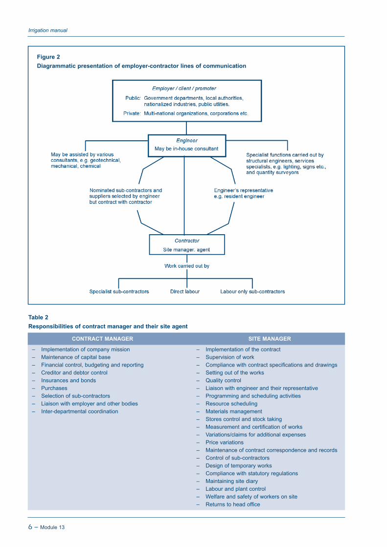
Resident engineer: A resident engineer is theengineer’s representative on the site of the works. Theresident engineer discharges the functions of theengineer upon delegation of such powers and authorityby the engineer in writing to the contractor. Otherwise,the duties of the resident engineer are to watch,supervise the works, test and examine materials to beused and the workmanship in connection with theworks. As shown in Figure 2, the engineer may appointpersons to assist the resident engineer. The contractorshould be notified of such persons and their functions.
Module 13 – 3
Chapter 2Contract management

They do not have power to issue instructions to thecontractor.
Contractor: The contractor is a company, firm orindividual who undertakes the execution of the works.From the contractor’s point of view, the contractmanager and the site agent are responsible for themanagement of the contract. The site agent is directlyresponsible for managing the contract on site. Fromthe employer’s point of view, the engineer isresponsible for managing the contract. Therefore, themanagement of the contract is a joint responsibility ofthe two parties at both management levels.
Project or contract manager: The project manager,also known/referred to as the contract manager, iseffectively responsible for contract management fromthe contractor’s point of view and provides back-upservices to the site agent. If the employer so wishes,they can also have a project manager.
Site manager or site agent: The site manager, alsoknown as the site agent, is the representative of thecontractor on the site of the works. The agent is a legalrequirement for most contracts. They receiveinstructions from the engineer, which become bindingon the contractor. As far as the contractor is concerned
Irrigation manual
4 – Module 13
Figure 1Overall employer-contractor roles and responsibilities

the agent is primarily responsible for the successfulcompletion of the works with due regard to time,workmanship, safety and the cost. The site agent isresponsible for a whole host of activities, chief amongwhich are: planning, organizing, administering,engineering, personnel and plant management, andfinancial control. Site management is in fact themanagement of resources. The resources are known asthe 5 M’s, being: Methods, Men, Machines, Materialsand Money. Besides this, the site agent also has tomanage time. This is the reason why there is a need forthe site engineer to have good resources and activityplans prior to the commencement of constructionwork. This has to be backed up by competent site staffand regular control and progress assessment meetings.The resource and activity plans are obtained by timescheduling for construction, which will be discussedlater.
Sub-contractors: The main contractor may decide tosub-contract part of the work to some other specialistfirms. Such firms, not forming part of the contract, areknown as sub-contractors. The engineer shouldapprove the choice of the sub-contractor. The maincontractor controls sub-contractors. The site personnelof the engineer, main contractor and sub-contractorshould be conversant that the aspects of the contractagreement and conditions, which govern theemployment of sub-contractors.
Figures 1 and 2 present the relationships between thedifferent parties involved.
Table 1 presents the division of the responsibilities betweenthe contractor and the engineer during the different stagesof the project, while Table 2 presents the responsibilities ofthe contract manager and their site manager.
Module 13 – 5
Module 13: Construction of irrigation schemes
Table 1 Division of responsibilities between contractor and engineer
CONTRACTOR ENGINEER
Head OfficeArrange insurance, etc. Check and approveAppoint site representative Ensure employer has advised contractor of the appointment
of the engineer
SiteExecution of work: Supervise:– Establish site – Establish site– Set out works – Check and approve– Site preparation, earthworks, foundations, etc. – Test, check and approve– Execute specified details – Supervise, check and approve– Manage sub-contract work – Supervise, check and approve– Query specifications and drawings – Clarify and issue variation order if necessary– Differ on instructions – Give opinion– Claim where necessary – Agree or otherwise and pay if valid1
– Order materials – Approve– Comply with labour regulations – Ensure– Manage and operate plant – Check ownership and approve– Measure work – Check, agree– Apply for payment – Check and authorize payment by issuing an Interim
Payment Certificate2
– Clear site – Issue Completion of Work Certificate3
Head Office– Maintain throughout maintenance period – Carry out final inspection– Apply for Final Certificate – Issue Final Certificate4
1 Head office may have to be involved.
2 The payment by the client should be within the specified time.
3 Completion of Work Certificate is usually accompanied by refund of some retention monies..
4 Refund of all retention monies becomes due and the contractor is relieved of their contractual obligations save for latent defects for which the contractorbecomes liable in perpetuity.
Irrigation manual
6 – Module 13
Figure 2Diagrammatic presentation of employer-contractor lines of communication
– Implementation of company mission– Maintenance of capital base– Financial control, budgeting and reporting– Creditor and debtor control– Insurances and bonds– Purchases– Selection of sub-contractors– Liaison with employer and other bodies– Inter-departmental coordination
– Implementation of the contract– Supervision of work– Compliance with contract specifications and drawings– Setting out of the works– Quality control– Liaison with engineer and their representative– Programming and scheduling activities– Resource scheduling– Materials management– Stores control and stock taking– Measurement and certification of works– Variations/claims for additional expenses– Price variations– Maintenance of contract correspondence and records– Control of sub-contractors– Design of temporary works– Compliance with statutory regulations– Maintaining site diary– Labour and plant control– Welfare and safety of workers on site– Returns to head office
Table 2 Responsibilities of contract manager and their site agent
CONTRACT MANAGER SITE MANAGER

2.2. Site management
The contractor’s site manager has a lot of responsibilities.For small projects they could just have an engineer, generalforeman, transport foreman, cashier, timekeeper andstorekeeper under their supervision. For large projects,they can be the chief executive of a site management team,comprising a compliment of professional technical andadministrative staff. In general, the larger the project thelarger the number of staff.
2.2.1. Staff management
The composition and responsibilities of the staff under thesite manager are generally as follows:
Engineering staff: Responsible for the design andgeneral guidance of all engineering works, such asprogrammes of construction and setting out.
General foreman: Responsible for the day-to-daydistribution of plant and labour, supervision of flow ofmaterials and upkeep of site communication systems.They are also the link between management andlabour.
Plant and transport managers: Responsible for therunning and maintenance of transport and equipmenton site. Uninterrupted transport and use of equipmentwill help improve the progression of the constructionactivities.
Office managers: Carry out administrativeresponsibilities of the project. These include accounts,stocktaking, cash transactions and generally ensuringthat the standing instructions from head office areadhered to.
Timekeepers: Record labour force attendance andprepare pay-sheets to submit to the office manager.They need to liaise closely with the foremen in order tokeep track of attendance of the labour force.
Storekeepers: Duties include checking in and out andsafeguarding all materials at the construction site. Theyalso receive and issue tools that will be used duringconstruction.
2.2.2. Materials management
Materials constitute a large proportion of the cost. Thecontractor needs to take care to purchase the right qualityand quantities at the correct place, time and price.
The employer’s engineer specifies and approves thematerials. The contractor’s site manager processes the
requisitions, places orders through their relevant staff,receives and holds the materials in store. The contractor’saccounts section then pays for the materials and maintainsthe receipts and records.
There is a need to ensure that the materials are correctlyused for the jobs they were purchased for in order to avoidwaste and theft. It is necessary to carry out random checksto ensure that the quantity received is equal to the quantityin works plus the quantity in stores. Storage facilities for theequipment and materials should be designed in such a wayas to minimize thefts or damage due to bad weather andbreakage. Materials should always be checked against theirinvoices.
2.2.3. Equipment management
Construction equipment or machinery is mainly selectedon the basis of technical performance and economicviability of utilizing that particular equipment instead ofanother equipment or instead of manual labour. Theconsiderations for either hiring or buying equipment forthe contract depends on:
The scale of works in terms of value and volume ofworks
The construction period
The methods of excavation, concreting, erection, etc.,envisaged in the contract
The type of equipment required and its marketavailability as well as cost of hire
The most important factor determining whether one buysor leases equipment is its utilization. Owning equipmentmeans being subject to the following costs: capital anddepreciation, residual value, interest and insurance.Operating the machinery involves costs such asmaintenance and repair, fuel, lubricants and otherconsumable costs as well as the operator’s costs.
The manufacturer provides the basic data on the output ofmachines. However, other factors, such as operator fatigue,site conditions, climate and others, have an effect onreducing the output as indicated by manufacturers.
When planning the purchase of new equipment or models,it is advisable to beware of the fact that some literatureprovided by suppliers may be misleading. Sometimesdemonstrations may be rigged and therefore it may be wiseto first hire the model for some time before actuallypurchasing it.
Module 13 – 7
Module 13: Construction of irrigation schemes

2.2.4. Maximizing profits
Profit is the difference between the income and the costs.From the point of view of the contractor, site managementshould maximize income and minimize costs. Goodplanning in order to avoid crisis management, making thecorrect choice of methods, good equipment and materialmanagement, good quality control and good relations withthe workforce all minimize costs. Ensuring correctmeasurement and claims and increased production canmaximize income.
The quality of work sets the platform on which the engineerand the site manager base their relationship and thereforeit determines the ultimate success of the project. This canbe a major source of disputes and can lead to high costs.Safety can be a high cost due to the cost of accident claims.The project costs are also related to the duration. Goodprogramming and progress control are the tools to be usedto minimize the progress-related costs.
2.2.5. Settlement of disputes
It is important to look at how disputes between thecontractor and the employer could be dealt with, as theycan be a cost to either party if not addressed carefully.
It is essential to document communications between theengineer and the site manager at each stage. Sometimes,what may appear to be a minor issue to the engineer may
be handled as a major issue by the contractor and vise versa.The engineer should copy all letters and communicationnotes to the employer so that they are well informed aboutthe possibility of a growing dispute. The most importantthing is to be as diplomatic as is possible. The followingguidelines on settlement of disputes can be followed and inthis order:
1. Conciliation: This is an informal gathering ofinterested parties who try to solve the problem byreciprocally giving some room to each other. If thisfails, either party could go for mediation.
2. Mediation: Mediation is a formal gathering with anexperienced chairperson as the mediator. Themediator will give an opinion, which is not binding toeither party. If mediation fails, the next option isarbitration.
3. Arbitration: The arbitrator has to be acceptable toboth parties. There are rules in every country of howarbitration should be conducted. Generally, therecommendations of the arbitrator are binding andthere is no appeal. However, any of the parties couldstill decide to go for litigation.
4. Litigation: In such a case the matter is brought tocourt. This is invariably an expensive and drawn-outaffair. Therefore, by all means and wherever possible,solutions for the disputes between the employer andcontractor should be found in-house.
Irrigation manual
8 – Module 13

The process of programming construction activities is acontinuous one. It involves organization, planning, controland re-organization. It incorporates all estimated resourcesrequired and the estimated time of completion of theactivities. Planning, involving activity and resource planning,is deciding what is to be achieved and how to achieve it. Itis a process of looking forwards and anticipating the future.
Control is comparing what has been achieved against whatwas planned and therefore looks backwards and taps onprevious experience. Re-organization is the re-orientationof the requirements according to the findings of the controlprocess. There are several techniques of programming,such as cumulative progress charts which are also known as‘S’ curves (Figure 3) or bar charts (Figure 4).
Module 13 – 9
Chapter 3Programming construction activities
Figure 3Cumulative progress charts or ‘S’ curves
Figure 4An example of a bar chart
Before any activities commence, an activity plan and aresource plan have to be produced. The activity (orprogramme progress) plan shows the activities completed,such as volume of trenching, pipe length laid and canallength constructed, depending on what detail is required.The resource plan shows the person-hours, the machinehours and the money used. The activity and resource planscannot be made without knowing the performance ofequipment and labour to be used on the project.
3.1. Equipment requirements
Below follows a short description of different types ofequipment that could be deployed for the construction ofan irrigation project and their common uses:
Bulldozer: Used to carry out works such as bushclearing, movement of soil for short distances, cuttingthicker layers of soil during land levelling, levelling ofanthills, making drains and flood bunds.
Scraper: Wheeled or crawled tractors pulling awheeled bucket of up to 30 m3 volume. The scrapercuts soil with a sharp blade at the front bottom of thebucket. The soil is stored in the bucket and can bereleased at the required location. These are ideal forcarrying soil over long distances, for example duringland levelling operations or to make up canalembankments.
Grader: A machine with a blade approximately halfway its frame. It is used to construct drains, roads, etc.,and to carry out more accurate land levellingoperations than a scraper can do. Graders can bemotorized or towed by a tractor. The latter are muchslower in carrying out the jobs and, depending on thejob, a powerful tractor is required for towing thesegraders.
Dragline: A machine with a bucket attached to ropes.The bucket can be thrown over a distance of up to15 m away. Draglines are used for excavation works inconstruction pits, for digging and cleaning canals, etc.
Excavator: A machine with a bucket, which ishydraulically operated. It is usually crawler mountedfor ease of working in muddy conditions. It can carryout the same jobs as the dragline although its reach isshorter, usually not exceeding 10 m. It is often used forcanal and pipe trench excavations and to load soil ontotippers.
Land plane : Consists of a long-wheeled frame with ablade. The blade is tilted forwards at the top. It is usedfor final land levelling and can be accurate to 2-3 cm.
Loader with backhoe: A large tractor-like machinewith buckets in front and behind. It is used forexcavations of canals and trenches for pipes, loadingsoil, etc.
Lorry: Used to carry materials and equipment to theproject site.
Tipper: Used to carry materials and equipment to theproject sites. They are suitable for transporting soil,sand and coarse aggregate as the back of the truck canbe hydraulically lifted, thus facilitating easy offloadingof bulky materials.
Lowbed with horse: A large, flat trailer usually pulledby a heavy vehicle, the horse. It is used to transportlarge machinery, such as bulldozers, scrapers andgraders over long distances to project sites.
Tractor and trailer : Used for transporting materialsand small equipment, usually within the project area.
Dumper: A small vehicle with a container in front.The capacity of the container can vary from 300 to1 300 litres. It is used to carry materials, such asconcrete, on the project site.
Concrete mixer: Has a pan or drum driven by anengine and is used for mixing concrete. The bladesinside the pan or drum facilitate the mixing of theconcrete. Some mixers have weighing equipmentattached, to mix the concrete by mass rather than byvolume. The size of the mixers can vary from as smallas 35 litres yield to well over 100 litres yield per mix.
Poker: A mechanically-moved stick used for thecompaction of concrete through vibration.
Bowser: A tank for storing water, fuel, etc., on projectsites. Bowsers have varying capacities and are normallymounted on wheels.
Roller or compactor: A heavy cylinder, which ismoved mechanically or by hand. It is used forcompacting soil. A compactor is also used forcompacting the soil, using a vibrating plate.
De-watering pump: This is a small pump used topump water away from the construction site, forexample trenches or construction pits.
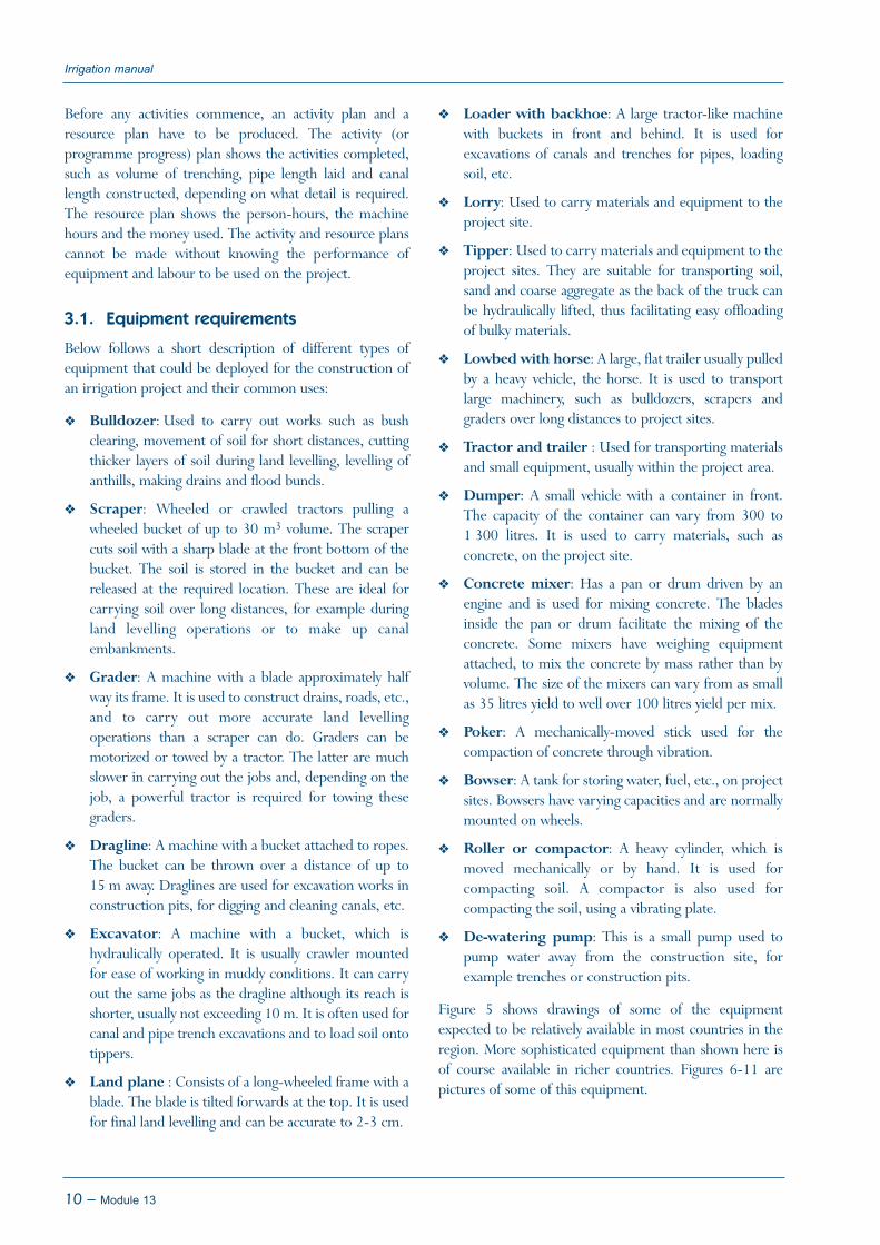
Figure 5 shows drawings of some of the equipmentexpected to be relatively available in most countries in theregion. More sophisticated equipment than shown here isof course available in richer countries. Figures 6-11 arepictures of some of this equipment.
Irrigation manual
10 – Module 13
Module 13 – 11
Module 13: Construction of irrigation schemes
Figure 5Examples of the different types of equipment used in construction works
Bulldozers
Graders
Excavators
Scrapers
637D 657B
D8K D9L D10
140G 14G 16G
235 245
Figure 6Wheel-tractor scrapers at work, CAT621G and CAT627G (Source: CAT, 2001)

Irrigation manual
12 – Module 13
Figure 7D10R Dozer (Source: CAT, 2001)
Figure 8A hydraulic excavator (Source: CAT, 2001)
Figure 9A motorized grader, CAT120H (Source: CAT. 2001)
Figure 10Wheel loader at work, CAT928G (Source: CAT, 2001)
3.2. Performance of some equipment
The manufacturer will provide the data pertaining to theperformance of a particular make of machinery. A bigdifference can occur between the performance quoted bythe supplier and the actual performance. This can beattributed to a number of factors, such as the skillfulness of
the operator, availability of a continuous supply of spareparts, lubricants, fuel, maintenance and repair, climaticfactors and site conditions among others.
For the purpose of this module, some data for estimatingearthworks have been provided, which can be used forestimating machine requirements for different jobs. Sincetime is needed for re-fuelling, repairs and othermaintenance work on the machines, it can be assumed thatthe net working time per machine is 5 machine hours pershift of 8 hours.
3.2.1. Bulldozer
For an average dozing distance of 50 m, the performancewould be:
Average soil (loose) : 60 m3/machine hour
Average gravel : 40 m3/machine hour
3.2.2. Scraper
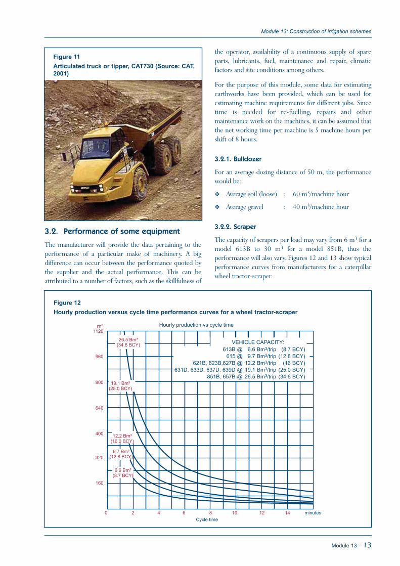
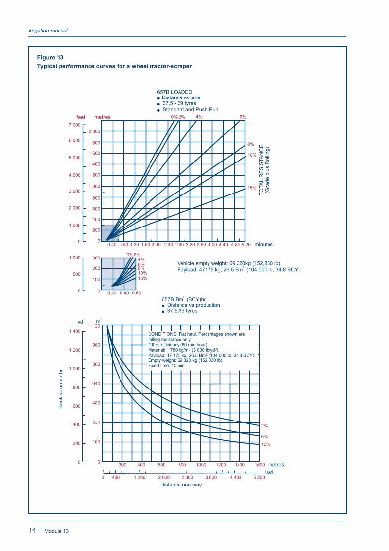
The capacity of scrapers per load may vary from 6 m3 for amodel 613B to 30 m3 for a model 851B, thus theperformance will also vary. Figures 12 and 13 show typicalperformance curves from manufacturers for a caterpillarwheel tractor-scraper.
Module 13 – 13
Module 13: Construction of irrigation schemes
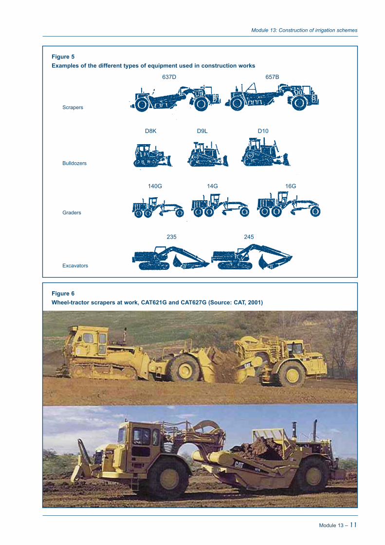
Figure 11Articulated truck or tipper, CAT730 (Source: CAT,2001)
Figure 12Hourly production versus cycle time performance curves for a wheel tractor-scraper
613B @ 6.6 Bm3/trip (8.7 BCY)615 @ 9.7 Bm3/trip (12.8 BCY)
621B, 623B,627B @ 12.2 Bm3/trip (16 BCY)631D, 633D, 637D, 639D @ 19.1 Bm3/trip (25.0 BCY)
851B, 657B @ 26.5 Bm3/trip (34.6 BCY)
Irrigation manual
14 – Module 13
Figure 13Typical performance curves for a wheel tractor-scraper
CONDITIONS: Flat haul. Percentages shown arerolling resistance only. 100% efficiency (60 min hour).Material: 1 780 kg/m3 (3 000 lb/yd3).Payload: 47 175 kg, 26.5 Bm3 (104 000 lb, 34.8 BCY).Empty weight: 69 320 kg (152 830 lb).Fixed time: 10 min.

3.2.3. Grader
With a relatively experienced operator, a grader can levelapproximately 0.5-1 ha per working day, assuming a cutand fill of up to 20 cm. The required time depends onthe soil type and the distances of soil movement. It isestimated that 50 m of 1.5 m wide field drains togetherwith 50 m of 2.5 m wide infield roads can easily be doneper hour.
3.2.4. Dragline
Table 3 gives estimates of excavation quantities fordraglines.
Table 3Excavation quantities for draglines
Excavation per Category Bucket size machine hour
(litres) (m3)
a 350 20a 700 35b 350 30b 700 50c 350 24c 700 45
a Digging or clearing of drainage channels with heavy weed infestation inwet conditions and dumping soil sideways.
b Digging channel in average soil in dry conditions and dumping soilsideways.
c As b but loading soil in dump-cart or lorry.
It should be noted that there should be a relationshipbetween channel size and bucket size. As an example, thereis no need to employ a dragline with a large bucket for theexcavation of a small channel.
3.2.5. Excavator
An excavator can be slightly more efficient than a dragline,but it has a smaller reach. A CAT215 excavator couldperform as follows:
Excavating and loading on a dump-cart or lorry: 45 m3/machine hour
Excavating and side dumping of soil: 65 m3/machinehour
3.2.6. Front-end loader with backhoe
The performance of a front-end loader with a backhoedepends very much on the power of the machine. Thebuckets of a tractor-powered machine should be muchsmaller than the ones of a large caterpillar 992C wheel loaderwith a bucket of up to 10.3 m3. Typical performance of acaterpillar 931B track-type with a backhoe is as follows:
If using the front-end loader:
Loading stockpiled average soil: 33 m3/machine hour
Loading stockpiled gravel: 28 m3/machine hour
If using the backhoe:
Excavating canal and loading tipper: 13 m3/machinehour
Excavating canal and dumping soil sideways: 18 m3/machine hour
3.2.7. Tipper
The performance of tippers to carry materials such as soildepends very much on the distance between the pit and theconstruction site, the road condition, etc. Under fieldconditions on dirt roads, the average carrying capacity of a 7-ton tipper is 3.5 m3 and the average speed is approximately15 km/hr loaded and 30 km/hr empty.
Module 13 – 15
Module 13: Construction of irrigation schemes
Example 1
Calculate the number of 7-ton tippers required to transport stockpiled soil, loaded by CAT931B using front-end loader,over a distance of 2 km.
Capacity of 7-ton tipper = 3.5 m3
Performance CAT931B = 33m3/machine hourLoading time = 3.5/33 hours or (3.5/33) x 60 minutes = 6.5 minutesTraveling time (loaded) = 2 km at 15 km/hour = (2/15) x 60 minutes = 8 minutesReversing and dumping = estimated at 2 minutesReturn traveling time (empty) = 2 km at 30 km/hour = (2/30) x 60 = 4 minutes
⇒ Total time = 6.5 + 8 + 2 + 4 = 20.5 minutes
The ratio of the loading time to the cycle time = 6.5 minutes : 20.5 minutes = 1 : 3.15
Thus 4 tippers are required to match the loading time of the loader.
3.3. Labour requirements
3.3.1. Labour for earthworks
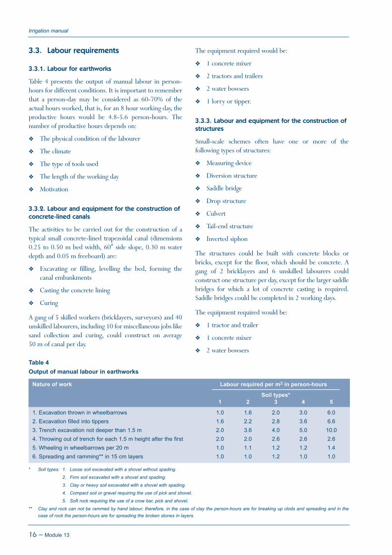
Table 4 presents the output of manual labour in person-hours for different conditions. It is important to rememberthat a person-day may be considered as 60-70% of theactual hours worked, that is, for an 8 hour working day, theproductive hours would be 4.8-5.6 person-hours. Thenumber of productive hours depends on:
The physical condition of the labourer
The climate
The type of tools used
The length of the working day
Motivation
3.3.2. Labour and equipment for the construction ofconcrete-lined canals
The activities to be carried out for the construction of atypical small concrete-lined trapezoidal canal (dimensions0.25 to 0.50 m bed width, 60° side slope, 0.30 m waterdepth and 0.05 m freeboard) are:
Excavating or filling, levelling the bed, forming thecanal embankments
Casting the concrete lining
Curing
A gang of 5 skilled workers (bricklayers, surveyors) and 40unskilled labourers, including 10 for miscellaneous jobs likesand collection and curing, could construct on average50 m of canal per day.
The equipment required would be:
1 concrete mixer
2 tractors and trailers
2 water bowsers
1 lorry or tipper.
3.3.3. Labour and equipment for the construction ofstructures
Small-scale schemes often have one or more of thefollowing types of structures:
Measuring device
Diversion structure
Saddle bridge
Drop structure
Culvert
Tail-end structure
Inverted siphon
The structures could be built with concrete blocks orbricks, except for the floor, which should be concrete. Agang of 2 bricklayers and 6 unskilled labourers couldconstruct one structure per day, except for the larger saddlebridges for which a lot of concrete casting is required.Saddle bridges could be completed in 2 working days.
The equipment required would be:
1 tractor and trailer
1 concrete mixer
2 water bowsers
Irrigation manual
16 – Module 13
Table 4Output of manual labour in earthworks
Nature of work Labour required per m3 in person-hours
Soil types*1 2 3 4 5
1. Excavation thrown in wheelbarrows 1.0 1.6 2.0 3.0 6.02. Excavation filled into tippers 1.6 2.2 2.8 3.6 6.63. Trench excavation not deeper than 1.5 m 2.0 3.6 4.0 5.0 10.04. Throwing out of trench for each 1.5 m height after the first 2.0 2.0 2.6 2.6 2.65. Wheeling in wheelbarrows per 20 m 1.0 1.1 1.2 1.2 1.46. Spreading and ramming** in 15 cm layers 1.0 1.0 1.2 1.0 1.0
* Soil types: 1. Loose soil excavated with a shovel without spading.
2. Firm soil excavated with a shovel and spading.
3. Clay or heavy soil excavated with a shovel with spading.
4. Compact soil or gravel requiring the use of pick and shovel.
5. Soft rock requiring the use of a crow bar, pick and shovel.
** Clay and rock can not be rammed by hand labour; therefore, in the case of clay the person-hours are for breaking up clods and spreading and in thecase of rock the person-hours are for spreading the broken stones in layers.

The normal practice is that a gang makes a number offoundations and slabs a few days in advance, after whichthey construct the walls and finish structures one by one.Thus the estimates above are working figures for planningpurposes. They can be modified during the control process.The sequence of construction can also vary.
3.4. Use of bar charts for programmingconstruction activities
After having calculated the time required to complete acertain job, one of several methods of programmingconstruction activities can be employed. As an examplehere, the bar chart is used. The inputs to programmingactivities and resources are obtained from the estimates thatare used in the preparation of bill of quantities for thedifferent irrigation systems (see Module 7, 8 and 9). Sincethe manner in which programming is done is the same forany construction activity, the surface irrigation system isused as an example for drawing up the time schedules forconstruction. Where more detail is required, activity andresource plans could be drawn up separately.
In order to be able to plan the activities well, it is necessaryto know which activity leads to what and how themachinery can be allocated to those activities withoutoverlaps. The number of machines and size of the labour
force depend on when the job has to be completed. It isimportant that all the materials and equipment necessary tostart the work and keep it going are on site when required.
Table 5 presents the bar chart for construction activities ofinfield works of the Nabusenga smallholder surfaceirrigation system (15 ha) that was designed in Module 7.This was a small job, as can be judged from the resourcesrequired and the construction period. In this case, thegovernment implemented the scheme and the irrigationengineer was at the same time the site manager and didboth the technical and non-technical work with the backupof head office staff.
The construction works to be done were as follows:
1 measuring device
980 m of trapezoidal canal with a bottom width of350 mm
725 m of trapezoidal canal with a bottom width of250 mm
1 400 m of drainage channel
1 600 m of perimeter road
15 ha land levelling
3 diversion structures, one-sided
Module 13 – 17
Module 13: Construction of irrigation schemes
Table 5Bar chart for the construction of a surface irrigation scheme for smallholder farmers
No Activity Month No. of Resources required
April May June July Aug days Labour Main machines
1 Site establishment --- 5 7-ton lorry2 Procurement of materials and -------------- 42 7 & 30-ton lorry;
transport to site train; tractor & trailer
3 Setting out grid and irrigation ------ 10 irrigation engineer;layout surveyor;
5 unskilled4 Canal construction -------------- 35 5 skilled; 7-ton lorry;
(980 m + 725 m) 40 unskilled concrete mixer;2 tractors & trailers,2 water bowsers
5 Land levelling (15 ha) -------------- 30 2 skilled; grader;2 unskilled land plane
6 Drains (1 400 m) ----- 5 2 skilled; grader2 unskilled
7 Roads (1 600 m) ----- 6 2 skilled; grader2 unskilled
8 Structures (12) -------- 16 2 skilled; concrete mixer;2 unskilled 2 tractors & trailers,
2 water bowsers9 Fencing (2 500 m) ------- 10 2 skilled; tractor & trailer
20 unskilled10 Finishing, clearing ------ 11 2 skilled; tractor & trailer
20 unskilled

1 canal-road crossing
3 saddle bridges
5 tail-end structures
2 500 m of fencing
It was assumed that 1 month has an average of 21 workingdays (if work is executed by a private contractor, 7 days perweek may be worked). The materials to be procured were:fine and coarse aggregates, cement, steel, fencing materials,formers and templates, grain bags, concrete pipes, slidinggates, check plates and siphons.
Irrigation manual
18 – Module 13

During the design process the engineer already beginsselecting the materials that are most likely to be used duringconstruction. The selection of materials is not only based onthe cost, but also on the availability of those materials, theavailability of skilled labour and the adherence to standards.This chapter briefly discusses some of the most commonmaterials used for constructing irrigation schemes, such as:
Concrete
Gabions
Bricks
Cement and concrete blocks
Timber
Reinforcement rods/wire
If piped sections are constructed, the following materialsmay be used:
Different types of pipes (uPVC, PE, AC, steel andaluminum)
Different types of fittings
Flow control, measurement, regulating devices
Automation devices, etc.
4.1. Concrete
Concrete is a mixture of fixed proportions of cement, fineaggregate (sand), coarse aggregate (crushed stone or naturalpebbles) and water. It is a favourable construction materialbecause it can be formed into almost any shape when it isstill fresh and, when hardened, it has the strength requiredfor many types of structures.
4.1.1. Important properties of concrete
A properly prepared concrete mixture should have thefollowing properties:
Good workability: It should be easy to place and compact
Cohesiveness: It should be sticky enough to prevent thecoarse aggregate from separating from the rest of themixture when it is being transported, placed andcompacted
Not too much bleeding: When setting, water rises to thesurface since the other mixture materials are heavierthan water. This process is called bleeding. Too muchbleeding gives poor finishing and can reduce thestrength of the concrete
The important properties of hardened concrete are:
Strength: This depends on the age of the concrete, thecement/water ratio, compaction and curing. Thestrength development is fast during the first few days,after which it gradually slows down until 28 days whenthere is little further gain achieved
Durability: Concrete should be durable, which dependson the cement/water ratio, compaction and curing
4.1.2. Concrete components
Concrete is made up of cement, fine aggregate (sand),coarse aggregate (stones) and water.
Cement is made from limestone and shale, which are burntat a high temperature to form cement clinker, which inturn is ground to the fine powder that is cement.
Sand is referred to as fine aggregates and is used to designateaggregates in which the nominal maximum size of particleis 4.75 mm. The sand particles should be smooth, roundedand hard. The sand required for the lining of canals isnormally available in nearby rivers.
Stones are referred to as coarse aggregates and havediameters ranging from 4.75 mm to 40 mm. The stonediameter selected for the preparation of concrete dependson the structure under construction. For example, for 5-cm thick concrete-lined canals the ideal stone size is 19 mm(¾ inch). The stones should be round or chunky, hard andstrong. Poorly-shaped stones, such as those that are flakyand long, should be avoided as this would mean that moreof the other materials are needed. The stones should beabout the same size.
Water used for making concrete should be clean. As a rule,water suitable for drinking is suitable to be used forconcrete.
Module 13 – 19
Chapter 4Types and use of construction materials
4.1.3. Batching
Batching is defined as the measurement of the quantities ofthe materials (cement, sand, stone and water) that go intoeach concrete mix. Batching should be done correctly as itaffects the workability, strength and cost of concrete.
Quantities can either be measured by volume or by mass.The most common method used is measuring by volume,as no expensive weighing equipment is required. Measuringby volume, also known as volume batching, is based onloose volume. It can be assumed that a 50 kg bag of cementis equivalent to 40 litres of loose volume and that the yieldof the mix is 60% of the loose volume of cement, sand andstone. This means that about 1.68 m3 of cement, sand andstone is required for the preparation of 1 m3 of concrete.
4.1.4. Concrete mixtures and mixing
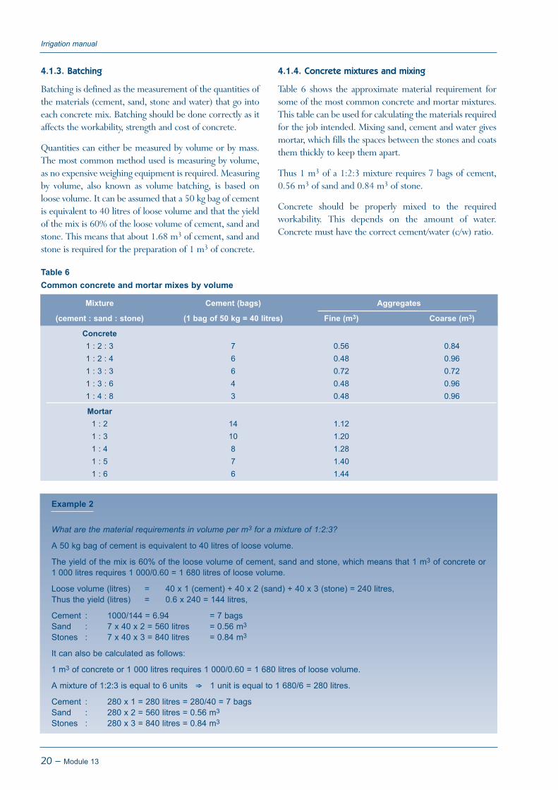
Table 6 shows the approximate material requirement forsome of the most common concrete and mortar mixtures.This table can be used for calculating the materials requiredfor the job intended. Mixing sand, cement and water givesmortar, which fills the spaces between the stones and coatsthem thickly to keep them apart.
Thus 1 m3 of a 1:2:3 mixture requires 7 bags of cement,0.56 m3 of sand and 0.84 m3 of stone.
Concrete should be properly mixed to the requiredworkability. This depends on the amount of water.Concrete must have the correct cement/water (c/w) ratio.
Irrigation manual
20 – Module 13
Table 6Common concrete and mortar mixes by volume
Mixture Cement (bags) Aggregates
(cement : sand : stone) (1 bag of 50 kg = 40 litres) Fine (m3) Coarse (m3)
Concrete1 : 2 : 3 7 0.56 0.841 : 2 : 4 6 0.48 0.961 : 3 : 3 6 0.72 0.721 : 3 : 6 4 0.48 0.961 : 4 : 8 3 0.48 0.96
Mortar1 : 2 14 1.121 : 3 10 1.201 : 4 8 1.281 : 5 7 1.401 : 6 6 1.44
Example 2
What are the material requirements in volume per m3 for a mixture of 1:2:3?
A 50 kg bag of cement is equivalent to 40 litres of loose volume.
The yield of the mix is 60% of the loose volume of cement, sand and stone, which means that 1 m3 of concrete or1 000 litres requires 1 000/0.60 = 1 680 litres of loose volume.
Loose volume (litres) = 40 x 1 (cement) + 40 x 2 (sand) + 40 x 3 (stone) = 240 litres,Thus the yield (litres) = 0.6 x 240 = 144 litres,
Cement : 1000/144 = 6.94 = 7 bagsSand : 7 x 40 x 2 = 560 litres = 0.56 m3
Stones : 7 x 40 x 3 = 840 litres = 0.84 m3
It can also be calculated as follows:
1 m3 of concrete or 1 000 litres requires 1 000/0.60 = 1 680 litres of loose volume.
A mixture of 1:2:3 is equal to 6 units ⇒ 1 unit is equal to 1 680/6 = 280 litres.
Cement : 280 x 1 = 280 litres = 280/40 = 7 bagsSand : 280 x 2 = 560 litres = 0.56 m3
Stones : 280 x 3 = 840 litres = 0.84 m3

Equation 1
c/w = mass of cement (kg)mass of water (kg)
If the c/w ratio is too low, the concrete will not reach therequired strength. If it is too high, cement is being wasted.Table 7 gives recommended c/w ratios and guidelines forconcrete mixes by volume batching for a range of concretegrades. Table 8 describes the different concrete grades andwhat grade is used for what type of construction.
Module 13 – 21
Module 13: Construction of irrigation schemes
Table 7Concrete mix proportions by volume batching for different concrete grades
Grade Nominal Compac c/w Mix proportions Materials per m3 Yieldstone -tion ratio per bag of cement of concrete per bagsize Sand Stone Water Cement Sand Stone(m) (m3) (m3) (litres) (bags) (m3) (m3) (litres)
Blinding 40 H 0.92 0.16 0.24 43.0 3.8 0.63 0.87 265V 0.90 0.17 0.28 41.0 3.4 0.59 0.94 295
20 H 0.92 0.18 0.19 45.5 4.0 0.73 0.75 250V 0.90 0.19 0.22 41.0 3.7 0.67 0.81 270
7 40 H 1.03 0.13 0.21 37.0 4.2 0.61 0.88 240V 1.01 0.14 0.25 38.0 3.8 0.58 0.94 265
20 H 1.03 0.15 0.17 36.5 4.4 0.71 0.75 225V 1.01 0.15 0.20 36.5 4.1 0.68 0.81 240
10 40 H 1.20 0.11 0.18 32.0 4.9 0.59 0.88 205V 1.18 0.11 0.22 32.0 4.5 0.56 0.94 220
20 H 1.20 0.12 0.15 31.0 5.2 0.69 0.75 190V 1.18 0.12 0.17 32.0 4.8 0.65 0.81 205
15 40 H 1.45 0.09 0.15 26.5 5.9 0.55 0.88 170V 1.42 0.09 0.18 27.0 5.4 0.52 0.91 185
20 H 1.45 0.09 0.12 26.5 6.2 0.65 0.75 160V 1.42 0.10 0.14 27.0 5.8 0.62 0.82 170
20 40 H 1.72 0.07 0.13 23.0 7.0 0.51 0.88 140V 1.67 0.07 0.15 23.0 6.3 0.49 0.95 160
20 H 1.72 0.08 0.10 22.5 7.4 0.61 0.76 135V 1.67 0.08 0.12 23.0 6.8 0.58 0.82 145
10 H 1.72 0.08 0.07 22.5 8.2 0.73 0.58 120V 1.67 0.09 0.08 23.0 7.7 0.74 0.62 130
25 40 H 1.85 0.06 0.12 21.5 7.6 0.50 0.89 130V 1.80 0.06 0.14 21.5 6.8 0.48 0.95 145
20 H 1.85 0.07 0.10 21.0 8.0 0.59 0.76 125V 1.80 0.07 0.11 21.5 7.4 0.57 0.82 135
10 H 1.85 0.07 0.07 21.0 8.9 0.71 0.58 110V 1.80 0.08 0.08 21.0 8.3 0.72 0.62 120
30 40 H 2.00 0.05 0.11 20.0 8.2 0.48 0.90 120V 1.94 0.05 0.13 20.5 7.4 0.46 0.95 135
20 H 2.00 0.06 0.09 20.0 8.6 0.57 0.76 115V 1.91 0.06 0.10 20.0 8.0 0.55 0.82 125
10 H 2.00 0.07 0.06 20.0 9.6 0.69 0.58 105V 1.94 0.07 0.07 20.0 8.9 0.69 0.62 110
H = compaction by hand (rodding and tamping).V = compaction by vibration (internal pokers).

The material should be loaded in the following order:
Stone and most of the water
Cement
Sand
Water to make up to the required volume
Mixing should be long enough to get the proper mixture.Normally 1.5 to 2 minutes should be sufficient. As aguideline, the time required for one mix of concrete in asmall mixer with a capacity of up to 500 litres isapproximately:
Filling : 3 minutes
Mixing : 2 minutes
Unloading : 3 minutes
Extra : 2 minutes
Overloading the concrete mixer should be avoided. Themixer should be cleaned at the end of a shift. This shouldbe done with a small quantity of stones and water, whichshould be mixed for a short while.
When mixing the components, the cement and the waterreact through a chemical process called hydration. Fine gels
Irrigation manual
22 – Module 13
Table 8Description of the various concrete grades
Grade Description Purpose
5 Blinding Rough stooling7 Mass concrete of roughest type Large, lightly-loaded footing and foundation pads; making up over excavation
in trenches; stooling; large, mass-gravity retaining walls10 Mass concrete Footings for one and two storey buildings; basements and foundation walls;
small dams and weirs; piers. Abutments and wing walls for small bridges; retaining walls
15 Unreinforced concrete Large foundations for non-vibrating machinery; dams and weirs; bridge piers abutments and wing walls. Floors in domestic buildings to receive light toppings with surface finishing
20 Standard structural-grade concrete General reinforced concrete construction in buildings; small bridges, culverts and silos; machine foundations; unrendered walls above ground; single course domestic and office floors on the ground; base course of light-loaded floors on ground to receive toppings
25 High-grade structural concrete Precast concrete fence posts and panels; machine foundations subject to vibration or shock; minimum for water-tight concrete and domestic driveways;light duty single course floors on ground (no trucking)
30 High Strength concrete High stressed reinforced concrete members; precast structural units; concrete subject to severe vibration or shock loading; specially water-tight walls and tanks; concrete roads; all paved areas to carry fork-lift trucks or for other heavy industrial uses; single course industrial floors or base courses of floors to receive strong toppings
Example 3
Concrete with a mix of 1:2:3 is to be mixed in a concrete mixer with a yield of 500 litres. The nominal stone diameteris 19 mm, the concrete grade should be 20. How much of each material should be batched per mix?
For such a mix Table 7 shows: c/w ratio = 1.67, cement = 6.8 bags, sand = 0.58 m3 (580 litres) and stones = 0.82 m3
(820 litres). The loose volume of 6.8 bags of cement = 6.8 x 40 litres = 272 litres. A c/w of 1.67 means that the volumeof water required = 272/1.67 litres = 163 litres.
The total volume of loose material = 272 (cement) + 580 (sand) + 820 (stones) + 163 (water) = 1 835 litres. Only 60%of this is the yield of concrete, which means that the actual yield = 0.6 x 1 853 = 1 101 litres. The mixer has a yieldof 500 litres. Therefore the ratio of the materials to be used per mix is 500 : 1 101 = 0.45.
Thus: 6.8 bags cement x 0.45 = 3.06 bags ≈ 3 bags0.58 m3 x 0.45 = 0.26 m3 sand0.82 m3 x 0.45 = 0.37 m3 stone163 litres x 0.45 = 73 litres of water.
Due to the fact that 7 bags instead of 6.8 bags would have to be used, the mix ratio in the earlier can still be used.The difference is very minor.

(hairs) start to grow around the cement particles andeventually the particles interlock and form a dense and rigidmaterial. This material acts as a paste (glue) to hold theaggregates together, thus giving the concrete mixture itsstrength. The gels continue to grow as long as there is water.Thus, the mixture must not dry out too quickly.
Example 3 shows the calculations that should be doneduring the batching process.
4.1.5. Transporting, placing, compacting and curingconcrete
Concrete should be transported as quickly as is possible sothat the quality of the concrete is not affected, meaningthat:
It should not dry up
It should not lose workability
It should not be contaminated, for example by soil ordust
It should not be diluted with water
There should be no segregation, for example stonestend to settle to the bottom of the mix because they arethe heaviest material in the mix
Concrete should be placed on clean surfaces. There shouldnot be a delay in placing concrete, as it would harden beforeit is placed in the formwork.
Concrete should be properly compacted so as to remove allair that is trapped in the mix. Compaction can be done byhand or mechanically by vibration. The thin layer ofconcrete for lining canals is usually applied using shovelsand screeding planks (straight edges), while the floats areused to finish the surface of the lining.
Newly placed concrete should not be allowed to dry outtoo soon as this will cause cracking, resulting in lowstrength and poor durability. Therefore, concrete should bekept wet for at least 2-4 weeks. Proper curing of concrete-lined canals is very important because the lining is thin and
the concrete is exposed to hot weather. It is thereforerecommended to cover the concrete with wet grain bags orother water-absorbing material as soon as the concrete hasset. The grain bags should always be kept wet. A few daysafter placing the concrete, the grain bags can be removedand the canal stretch be filled with water, which should staythere for 2-4 weeks. The freeboard of the canal is normallynot covered by water in this case. The latter should bewatered 3-5 times per day, depending on the weather.
4.1.6. Steel reinforcement
Concrete is strong in compression, but weak in tension. Itcan withstand crushing forces, but breaks easily when apulling force is applied or when there are one-sided forcesworking on the concrete. Steel reinforcement givesconcrete the tensile strength it requires against externalforces. Steel should be properly stored, ideally off theground, especially in muddy areas. It should be kept clean.When used in a structure, it should be properly fixed in aposition with plastic spacers or mortar blocks and tiedtogether with soft wire.
The minimum concrete cover over the steel should be40 mm. A diameter of 8-10 mm plain steel is normallysufficient for the works required in smallholder irrigationschemes. Steel requirements are normally given in units ofmass. The mass per m3 of steel is 7 850 kg. This can beused together with the diameter of the steel to calculate thelength of steel to be ordered.
4.1.7. Mass concrete
Mass concrete is concrete mixed with large stones orboulders. It is often used in large, voluminous structuresthat do not require a high strength, such as the apron floorof a weir. Mass concrete is made by placing layers ofconcrete in the structure and throwing in the stones orboulders. This mixture should then be properly compacted,preferably by mechanical vibration, for example a poker, asa lot of strength is required to mix the large stones orboulders with the concrete.
Module 13 – 23
Module 13: Construction of irrigation schemes
Example 4
The length of steel, with a diameter of 8 mm, required for Nabusenga irrigation scheme is 4 000 metres. How manytons of steel should be ordered for the project?
The volume of 100 m of steel is equivalent to the cross-sectional area of the steel multiplied by the length, thus:
¼ x π x d2 x length = ¼ x 3.14 x (0.0008)2 x 100 = 0.005 m3.
The weight of this length is: 0.005 x 7 850 = 39.25 kg.
4 000 metres of steel will therefore weigh: 4 000/100 x 39.25) = 1 570 kg = 1.57 tons.

4.2. Gabions and Reno mattresses
Gabion baskets and Reno mattresses are cages or basketsmade from double-twisted, metallic-coated wire mesh,which is made like pignetting. Gabions are manufacturedwith a 8 x 10 mesh type, having a nominal mesh opening of83 mm x 114 mm. Gabions come in different sizes. Themost common sizes are 1 x 1 x 1 m, 1.5 x 1 x 1 m, 2 x 1 x0.5 m, 2 x 1 x 1 m, or 4 x 1 x 1 m. Reno mattresses aremanufactured with a 6 x 8 mesh type, having a nominalmesh opening of 64 mm x 83 mm. Their most commonsize is 4 x 2 x 0.23 m or 6 x 2 x 0.23 m. Sometimes thethickness can also be 0.17, 0.30 or 0.50 m instead of0.23 m. The cages are filled with stones, well packed. Thematerial used to fill the gabions must be 10-20 mm durablestone. Structures are quite easy to construct using gabions.The construction is labour intensive, but little skilled labouris required. The structures are permeable and flexible.Permeability is acceptable for weirs as long as the upstreamside is sealed off. To avoid the loss of soil under thestructure, a terram filter should be laid on the base soil, asshown in Figure 14. This filter allows water to infiltrate butdoes not allow sand and other particles through.
4.3. Bricks and cement or concrete blocks
Bricks and concrete or cement blocks can be used for smallstructures, and sometimes for lined canals in small-scaleirrigation schemes. If suitable soils are available in a projectarea, farmers could mould and burn their own bricks forconstruction. Although brick-lining of canals is cheapcompared to concrete lining, it takes much more time toaccomplish. Brick lining also requires plastering on bothsides of the walls to protect the bricks and to give a cleanview of the structure.
The cement-stabilized soil block is mainly soil and water,with cement acting as the stabilizing agent. Sizes can be290 x 240 x 90 mm or 240 x 140 x 90 mm. A desirablesoil should consist of gravel, sand, silt and clay. Animportant factor that affects the strength of the finishedblock is the fines content of the soil, i.e. the silt and claycontent. The desirable range of the fines content is from20-30%.
Concrete blocks could also be cast. The use of solid orhollow concrete blocks instead of the traditional bricks canbe desirable for meeting the demands of good quality, speedof construction and overall economy. Blocks may be used inthe following sizes: 400 x 300 x 200 mm, 400 x 200 x200 mm, 400 x 100 x 200 mm. Such blocks can be cast atthe site using a mix proportion of 1:3:6, with a gravel sizeof maximum 20 mm, or in the ratio of 1:4:8 or 1:5:10. Aminimum water cement ratio should be used. The cementcontent should be about 150 to 200 kg/m3 of concrete.The blocks should be compacted and cured properly. Thecuring is normally done for first 14 days by keeping themcontinuously moist followed by 14 days of air drying.
Construction usually involves the plastering of bricks/blockin order to protect them and also give a good finish to thestructure. Mortar mixes are given in Table 6.
4.4. Timber
Timber can be used to make small structures such as canaloutlets. It is also often used as shuttering material, becauseit is easy to cut and join. Shutters form a mould which canshape concrete and support it until it dries. Hardwoodshould be used.
Irrigation manual
24 – Module 13
Figure 14An example of a gabion basket structure
4.5. Pipes and fittings
4.5.1. Types of pipes and fittings
The most common pipes used in irrigation are asbestoscement (AC) pipes, unplasticized polyvinyl chloride (uPVC)pipes and polyethylene (PE) pipes. The types of pipes andtheir fittings are discussed in detail in Modules 7, 8 and 9.All pipes can be subjected to different levels of pressures,provided they are manufactured to withstand that pressure.As a result, each pipe and fitting must conform to the setstandards. Generally, the materials need to be marked asfollows in order to show that they are certified by astandards body where they were manufactured:
Pipes – The manufacturer’s trade name or trademark of product
– The class of the pipe
– The nominal size of the pipe
– Batch identification
Fittings – The manufacturer’s trade name or trademark of product
– The class of the fittings
– The nominal size of the fitting, whenrelevant, of the branch limb
– In the case of threaded adapter bushes, thesize, shape and form of the thread
Adhesives – The manufacturer’s trade name or trademark of product
– Suitable identification of the product
– Date of manufacture
– Words such as ‘FLAMMABLE’
– Batch identification
On-site inspection for compliance with specifications hasto be carried out. The inspection can result in theacceptance or rejection of a given consignment by theengineer. The engineer therefore has to take samples afterchecking for compliance of markings. The samples can beused for adjudication in cases of dispute. Some guidelinesfor sampling are:
Pipes or fittings: 4 to 16 pieces from a consignment of100 to 10 000, in this instance checks are made onlengths of pipe or fittings with their rubber rings
Adhesives: randomly take 1 container of adhesive fromthe consignment
4.5.2. Packing, transporting, storing and handling ofpipes and fittings
Pipes and fittings should be packed to protect them againstdamage during transportation. Pipes should not come intocontact with sharp objects, nor should they project beyondthe body of the vehicle transporting them. Therefore theyshould be well secured along their full length. Rubber jointrings should not be contaminated with oil or grease.
Before uPVC pipes are transported to the site, theyshould be stored, not more than 1.5 m high (or about 7pipe layers under cover in pipe racks) which providesupport to the full length of the pipe. Different diameterpipes should not be stacked together. Once on site, theuPVC pipes should be stored on level ground that is free
Module 13 – 25
Module 13: Construction of irrigation schemes
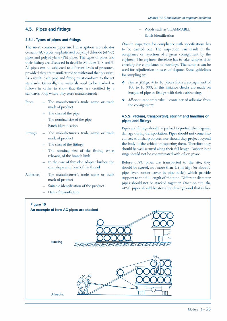
Figure 15An example of how AC pipes are stacked

of sharp objects. They should be stacked no more than1 m high in a stack, formed by cross formation of pipes.Again, pipes of different sizes should not be stackedtogether.
AC pipes should be stacked in layers on top of 100 mm x75 mm battens, both during transportation and storage onsite (Figure 15). On site they can also be stacked using aclose packing formation. When unloading AC pipes ofdiameter 100 mm to 400 mm, ropes and skids should beused to roll the pipe on the skid from the truck to theground. The rope is used to hold the pipe as it rolls down.
Ideally for pipes from 450 mm to 600 mm, mechanicalequipment should be used to lift and place them on theground. In the absence of this, ropes and skids can still beused. When unloading AC pipes along the trench, aninterval of 0.3 m between the pipes is ideal. Pipes less than200 mm in diameter can be lowered into the trench byhand, larger diameter pipes should be lowered bymechanical means such as cranes, front-end loaders, etc.
Rubber jointing rings fittings and adhesives should bestored in their original packing in a cool dry place.
Irrigation manual
26 – Module 13
Whatever the construction method, it should be assuredthat the canal embankment is well compacted and stable.The embankment should be built up in layers, whichshould be well compacted, with the soil having the correctmoisture content. After completing the construction of theembankment, the canal shape should be excavated, eithermanually or mechanically. Alternatively, the banks of thecanals could be built around the canal section, using canaltemplates. If the canal is lined, it has to be assured that thethickness of the lining material is added to the canal sectionto be excavated.
If the canal sides are not too steep and water is available forcuring, in-situ lining can be considered. Alternatively, pre-casted slabs can be made at a central place of the scheme,where there is access to water. The size of the slabs shouldbe such that they are easy to handle and that they do notbreak when lifted. Shutters can be made of steel, timberand other materials.
5.1. Setting out canals
The first step in the construction of canals is the setting outof the canal alignment and elevations. This is done usingsurvey instruments and pegs. For setting the canal levels,
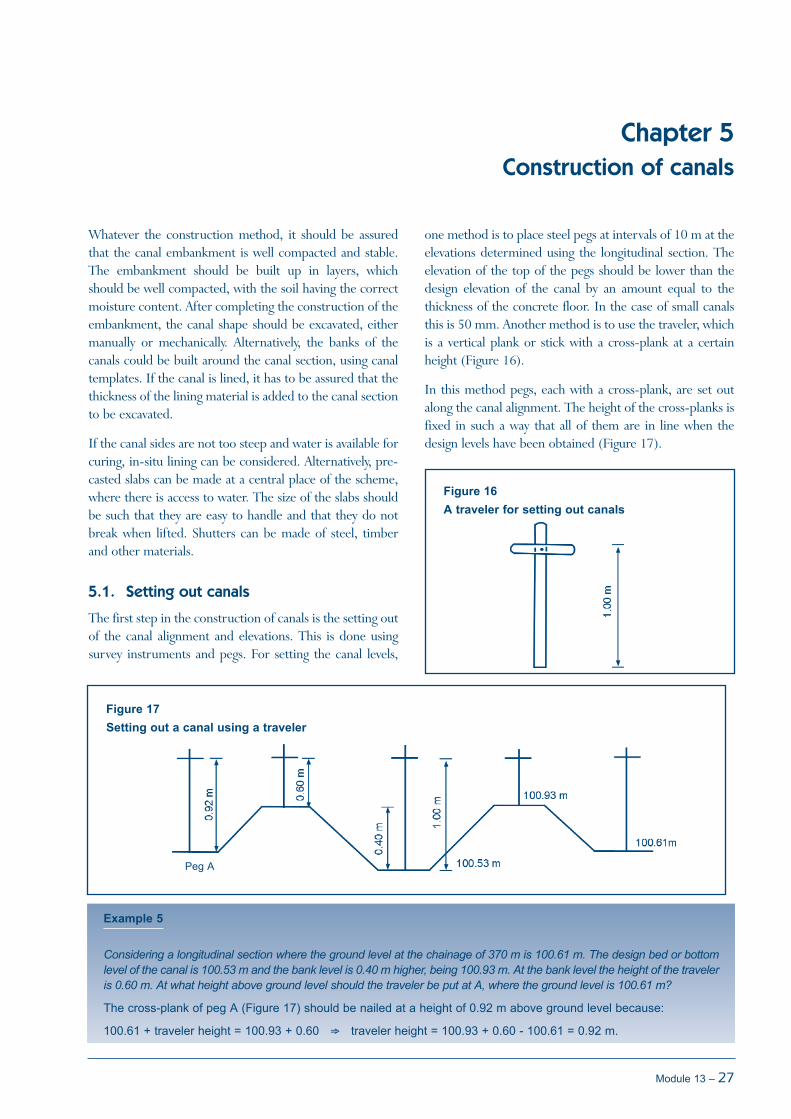
one method is to place steel pegs at intervals of 10 m at theelevations determined using the longitudinal section. Theelevation of the top of the pegs should be lower than thedesign elevation of the canal by an amount equal to thethickness of the concrete floor. In the case of small canalsthis is 50 mm. Another method is to use the traveler, whichis a vertical plank or stick with a cross-plank at a certainheight (Figure 16).
In this method pegs, each with a cross-plank, are set outalong the canal alignment. The height of the cross-planks isfixed in such a way that all of them are in line when thedesign levels have been obtained (Figure 17).
Module 13 – 27
Chapter 5Construction of canals
Figure 16A traveler for setting out canals
Figure 17Setting out a canal using a traveler
Example 5
Considering a longitudinal section where the ground level at the chainage of 370 m is 100.61 m. The design bed or bottomlevel of the canal is 100.53 m and the bank level is 0.40 m higher, being 100.93 m. At the bank level the height of the traveleris 0.60 m. At what height above ground level should the traveler be put at A, where the ground level is 100.61 m?
The cross-plank of peg A (Figure 17) should be nailed at a height of 0.92 m above ground level because:
100.61 + traveler height = 100.93 + 0.60 ⇒ traveler height = 100.93 + 0.60 - 100.61 = 0.92 m.
Peg A

Irrigation manual
28 – Module 13
Figure 18Metal template for shaping canals (60° angle)
NO
TES:
–Al
l wel
ded
mem
bers
sha
ll be
eve
nly
wel
ded
–1
m3
stee
l wei
ghs
7.85
0 kg
–C
omm
on c
anal
bed
wid
ths
(b) a
re 2
50, 3
00, 3
50, 4
00 a
nd 5
00 m
m, b
ut c
ould
be
mad
e to
any
siz
e.

Module 13 – 29
Module 13: Construction of irrigation schemes
NO
TES:
–Al
l dim
ensi
ons
in m
etre
s, u
nles
s ot
herw
ise
stat
ed–
All w
elde
d m
embe
rs s
hall
be e
venl
y w
elde
d–
1 m
3st
eel w
eigh
s 7.
850
kg–
Com
mon
can
al b
edw
idth
s (b
) are
250
, 300
, 350
, 400
and
500
mm
, but
cou
ld b
e m
ade
to a
ny s
ize.
Figure 19Trapezoidal canal former (60° angle)

5.2. Canal formation
After setting out the canal, the second step is to open andlevel the ground in a strip as wide as the bed or bottomwidth. The correct level can be checked with a wire orstring in between two steel pegs.
The third step is to form the canal embankments. For thisexercise templates are used (see Module 7). Thetemplates can be made of sheet metal with a length of3 m. The outside dimensions are 50 mm greater than theinside of the finished, lined canal. Once the template isaligned the soil is compacted around it in layers of 100 to150 mm.
Mechanized canal formation is used in the construction oflarger projects, or if labour costs are prohibitively high. It isused for soil transport, compaction and excavation.
Figures 18 and 19 show some of the equipment used incanal formation.
First of all, an embankment is made up to bank level. It ismade from the soil excavated to form the canal section orsoil is brought to the sides from elsewhere. The soil is piledon the embankment in such a way that it gives the finalrequired canal bank and canal shape. Figure 20 shows thefinal cross-section (broken line) and the initialembankment with bed width b.
The fill is either collected from excavated drains, nightstorage reservoirs or from borrow pits outside theirrigation area. For large schemes, where machinery such asscrapers are used, a transport programme is made on whichis indicated the most economic path for the cut to be usedas fill (Figure 21). Such a transport programme is usuallythe basis on which contractors are paid.
Irrigation manual
30 – Module 13
Figure 20Final cross-section and initial embankment of a canal
Example 6
The cut should be sufficient to fill 2 parallelograms, shown in Figure 20, each with base a. What are the cut and fitvolumes?
As the canal cross-section is known, the cut cross-section can be calculated as follows:
tg60 = 0.40
⇒ x = 0.40
= 0.23 mx 1.73
½ x (bottom width + top width) x canal depth = ½ x (0.40 + (0.40 + 0.23 + 0.23)) x 0.40 = ½ x 1.26 x 0.40 = 0.25 m2
The fill cross-section is: 2 x a x 0.32 (area of a parallelogram is base x height).
The fill should equal the cut, thus: 2 x a x 0.32 = 0.25 m2 ⇒ a = 0.39 m.
This results in an embankment bottom width b = 2.50 - 2 x 0.39 = 1.72 m.
and in an embankment top width c = b - (2 x (100.93 - 100.61)) = 1.72 - 0.64 = 1.08 m
The fill of the original embankment is ½ x (b + c) x embankment height.
Thus, in the example: ½ x (1.72 + 1.08) x 0.32 = 0.45 m3 per metre length.

To ease the construction of the canals, several points areindicated with pegs (points A-D in Figure 20). From theexample it follows that points B and C have a distance ofb/2 or 1.72/2 = 0.86 m to the centre line peg (seeExample 6 for the calculation of b). The operator knowsthat the foot of the embankment should begin at point Band C and, when excavating, that the final bank footcommences at points A and D, which have also beenindicated with pegs.
Care should be taken not only to construct the correctcross-section, but also the correct canal gradient(longitudinal profile). One should use a level instrument tocheck the canal bed elevation at about every 5 to 10 m (seeModule 7 for more details).
6.3. Placing and curing concrete
After aligning the canal and forming it, the next step is toplace the concrete. To facilitate this, formers of 4 m length,also called screeding frames, with screeding edges 2 m apartare used. A builders line (which has notches in the middle)should be installed to centre the former and to keep thecorrect gradient. Concrete is placed in position with a
straight edge, after which it is finished with a wooden floatand steel trowel or steel float. Expansion joints are made at2 m interval, related to the screeding edges. After curing,these joints should be filled up with bitumen seal.
Concrete canals should have shrinkage joints to allow forthe expansion and contraction. The joints should beprotected using bitumen materials to avoid leaking. The soilsupporting the concrete lining should be well compacted toavoid soil settlement and thus cracking of the lining. Typicalsmall canals can have joints at about 2 m intervals.
The concrete lining could be constructed in-situ or withpre-cast slabs. The thickness should be 50-70 mm fornormal conditions. A simple shutter frame that can be usedfor construction of pre-cast slabs is shown in Figure 22.
Curing concrete or sand-cement mixtures is veryimportant. It should be kept wet for 2-3 weeks, initially byspreading polyvinyl sheeting or grain bags that are kept wetcontinuously over the newly placed mixture, and afterinitial hardening by filling the canal section with water forabout 2 weeks. To prevent pre-casted slabs drying out tooquickly, they could be covered by grass.
Module 13 – 31
Module 13: Construction of irrigation schemes
Figure 21The transport programmes for the cut and fill process during canal formation

Irrigation manual
32 – Module 13
Figure 22Timber shutter frame for concrete slab casting

Construction of underground pipelines involves the initialsetting out of the trench, the actual trenching, preparationof the trench bottom, bedding, pipe laying, pipe jointing,back-filling, placing thrust blocks and pressure testing.
6.1. Trenching, bedding and pipe laying
Reference points or benchmarks should be used in settingout the width and centre line of trenches. The width of thetrench at the depth equivalent to the crown of the pipeshould be at least 30 cm greater than the nominal diameterof the pipe. The part of the trench above the crown shouldbe of a convenient width.
Trenching can be quite tedious if the ground is hard andlarger diameter pipes are to be used. Trenches are dug usingpicks, mattocks and shovels, but if rock outcrops areencountered in the process, some blasting may be calledfor, depending on the severity of the situation. Localtechniques can also be used to deal with rock outcrops, likeheating and fast cooling to weaken the rocks and thenhitting them with a hammer.
For AC pipes in areas where there is no road crossing thepipeline, the minimum recommended cover over the pipeshould be at least 45 cm. For areas under roadways, itshould be 60 cm for medium load and 90 cm for heavyload. This is to avoid the anticipated load damaging thepipe. For uPVC pipes, ASAE EP340.2 standardsrecommends a minimum cover of 75 cm and a maximumof 120 cm when traffic will be passing above the pipe.When no traffic will be passing, the same standardrecommends at least 45 cm cover for 63 mm uPVC pipes,and at least 60 cm for larger pipes.
The bottom of the trench should be level or of a uniformslope, to accommodate the full length of the pipe. Wherean uneven trench bottom is encountered, especially inrocky or hard ground, a 10 cm (or at least one third ofnominal diameter) fine back-fill or bedding should beprovided for during setting out, especially in the case of ACpipes. This layer has to be back-filled, using suitablebedding material such as free-draining coarse sand, gravel,loam or a soil of friable nature, and be leveled. In the caseof fittings, such as the couplings of AC pipes, excavation inthe back-fill should be made to accommodate the fittingsuch that the pipe remains level.
6.2. Pipe jointing
When pipes have to be joined, they have to be clean of dirt.All the solvent cleaners, adhesives and lubricants used injoining pipes should be those recommended by themanufacturer of the pipe or fitting. It has to beremembered that solvent cleaners and adhesives are highlyvolatile.
For uPVC piping less than 200 mm in diameter, aninjection-mould adhesive type of fitting or an integralrubber ring should be used. For sizes larger than 250 mmdiameter, a rubber ring end socket should be used. For ACpipes of 200 mm diameter, pipes can be jointed, via thecoupling, by hand. Larger diameter pipes should bemechanically jointed. In both cases, a lubricant should beapplied up to the witness groove and the alignment of thepipe up to the coupling should be well done. Both uPVCand AC pipes can be cut if shorter pipes are needed. Ifjointing is not done immediately, the pipes have to betemporarily closed in order to avoid the entrance of animalsor dirt. It also is important to ensure that the temporaryclosures are opened on re-commencement of pipe laying.Valves and outlets should be closed every day.
Figure 23 shows a pamphlet used by Agritex in Zimbabweto explain how uPVC pipe jointing should be done.
6.3. Back-filling
After checking that the levels of all joints are correctly setout, side filling can then be done in layers that are 75 mmthick, using fine material for the fill. The layers have to betamped by hand, ensuring that the joints are left exposed.Tamping should be done simultaneously on both sides ofthe pipe, in order to avoid misalignment. This shouldcontinue up to a height of two thirds of the pipe diameter,or up to 10 cm above the crown when the material is spreadover the whole length of the pipeline except the joints.Beyond that, the rest of the back-filling can be done inlayers of 15-30 cm. The trenches should be over-filled toallow for settlement. The space between the joints is back-filled after the pipeline has been pressurized and the jointsinspected to ensure that there are no leaks (see below). It isnecessary to ensure that all pipes are back-filled once theyare installed, in order to prevent them from floating due torainwater or groundwater.
Module 13 – 33
Chapter 6Construction of pipelines

AGRITEXMASVINGODrawn : RRDate : 1988
6.4. Thrust blocks
Thrust blocks transfer the load from a fitting or branch toa wide load-bearing area, thereby minimizing the chancesof the fitting moving. They are required:
When the pipeline changes direction
At the end of a pipeline
When there is a branch such as a tee
6.5. Pressure testing and flushing of thesystem
The purpose of testing pipelines is to ensure that the pipejoints are water-tight and that the permanent concrete
thrust blocks are capable of resisting the load. Normally,at least 7 days should be allowed after constructing thelast thrust block before the system is tested. By this time,the last thrust block should be able to withstand the load.When pressure testing, the pressure should not exceedone and half times the maximum working pressure. It isalso important that the valves and all other outlets beopened and closed slowly.
The flushing is intended to remove all the dirt thatinevitably gets into the system during pipe laying and itshould be done for a couple of hours with the flush valvesat the end of the lateral lines open. The flushing processshould be stopped once clean water starts coming out ofthe valves.
Irrigation manual
34 – Module 13
Figure 23uPVC pipe jointing technique
4. While cement is still wet insertspigot into socket – push righthome in a straight movement.
5. Hold the completed joint forapproximately 30 seconds to allowthe initial grab to occur, then leaveas undisturbed as possible for 24hours when pressure can be turnedon.
Note: Prodorite Solvent Cement ishighly volatile and to reduceevaporation to a minimum STOREIN A COOL PLACE and replace lidimmediately after use.
1. Clean both ends to be joined ofany loose dirt, earth or grit andremove oil, grease or paint. Lightlysand paper inside of socket andoutside of spigot.
2. Apply light priming coat of solventcement to inside of socket ofspigot and allow it to dry.
3. Apply second coat, sparingly, toinside of socket and more liberallyto outside of spigot. With too muchcement in the socket, a pool of thisliquid will form which can result infailures at this point.

Proper land clearance and levelling are important forefficient irrigation, especially in surface irrigation schemes.It involves bush clearance and moving soil in order to havelevel fields for basin irrigation or uniform sloping fields forfurrow or border strip irrigation.
Bush clearance in small schemes can be done manually byusing axes, picks and shovels for cutting trees and bushesand uprooting trunks. For large areas, or if no manuallabour is available, equipment such as bulldozers and heavytractors are used.
7.1. Initial land levelling
Initial land levelling is usually done using bulldozers,scrapers, graders and land planes. Bulldozers are used tomove soil over short distances, while scrapers are used tocarry soil over longer distances. This machinery is not veryaccurate and elevation differences of up to 100 mm mightstill remain. The final, accurate land levelling is done withgraders and tractor-towed land planes in particular, whichusually achieve accuracy to within 25 mm of the desiredlevels. Settlement of fill will always occur and therefore theland levelling often has to be repeated after the end of thefirst year of cultivation. Fine levelling using a land plane isrecommended after every ploughing.
A detailed topographic survey, preferably grid, is needed tocalculate the most economic land levelling requirements.Based on the spot heights of the grid points and the requiredgradient of the land, the cut and fill can be calculated. The
total volume of cut should preferably exceed the total volumeof fill by 10-50%, depending on the total volume to bemoved and the compressibility of the soil.
The three most widely used methods for calculating theamounts of soil cuts and fills are:
Profile method
Contour method
Plane or centroid method
These methods are described in detail in Module 7.
7.2. Pegging final levels
The depths of fill or cut required are indicated in the fieldwith pegs. Usually, the pegs of the grid survey are used.Painted lines on the pegs indicate the depth of cut or fill asshown in Figure 24. These painted lines are placed at thecorrect elevations with a level instrument. Starting from abenchmark with known elevation, the bottom of the staffshould be placed at the correct elevations as obtained fromthe land levelling calculations.
In Figure 24 the benchmark elevation is 88.500 m and theelevation after land levelling for peg 1 should be 88.916 m.The backward reading to the benchmark is 1.950 m. Thusthe height of point of collimation (HPC) is 88.500 m +1.950 m = 90.450 m (see Module 2). As the paint shouldbe at elevation 88.916 m, the staff should be placed suchthat the staff reading is 90.450 m - 88.916 m = 1.534 m.
Module 13 – 35
Chapter 7Land levelling
Figure 24Indication of cut and fill in the field
Peg 1

The machine operator cuts or fills the land to the requiredlevel, taking into account the most economic route fromcut to fill. As already indicated in the beginning of thischapter, scrapers should preferably be used to move largevolumes of soil over longer distances. Although this couldbe achieved with a grader, it would be a time-consumingand thus very expensive process.
It is important to make a final check to make sure that thedesired levels have been reached before the pegs areremoved.
Irrigation manual
36 – Module 13

CAT. 2001. Caterpillar Catalogue.
Cement and Concrete Institute. 1986. Concrete construction. A handbook. Harare.
Council of South African Bureau of Standards (SABS). 1976. Standards specifications for components of unplasticized polyvinylchloride (uPVC) pressure pipes for potable water. Pretoria. 55 p.
Hardie’s Fibrolite. 1969. Low head irrigation pipe. Sydney. 8 p.
Zimbabwe Institute of Engineers and Construction Industry Federation of Zimbabwe. 1995. Project management coursehandbook. Harare.
Zimbabwe Institute of Engineers in association with Construction Industry Federation of Zimbabwe. 1997. Construction sitemanagement course handbook. Harare. 62 p.
Zimbabwe Institute of Engineers, Federation of Civil Engineering Contractors, Zimbabwe Association of ConsultingEngineers. 1984. Zimbabwe general conditions of contract (ZGCC). 4th Fourth edition. Harare. 31 p.
Module 13 – 37
References

Irrigation manual
38 – Module 13