assembly, installation, operation and maintenance...
TRANSCRIPT

All Products limited to Vehicle Tow Rating; see Vehicle Owners Manual October 23, 2014 See www.huskytow.com for Warranty Information/Tech Support. ©(2014)Husky Towing Products
Page 1
Rating when used as a weight distribution hitch with spring bars Part Number Max. Tongue Weight Max. Gross Trailer Weight
32215 / 32216 400-600 lbs. 6,000 lbs. 32217 600-800 lbs. 8,000 lbs. 32218 800-1200 lbs. 12,000 lbs.
CAUTION: The tongue weight rating of spring bars represents the capacity of a pair of bars,
NOT an individual bar.
Rating when used as a weight carrying hitch without spring bars Part Number Max. Tongue Weight Max. Gross Trailer Weight
32215, 3226, 32217 & 32218 600 lbs. 6,000 lbs. Always use a pair of spring bars and be sure they are of the same weight rating and size for your trailer.
READ ALL INSTRUCTIONS AND CHECK PACKAGE CONTENTS BEFORE BEGINNING INSTALLATION. Note: This system can be used on any angle tongue trailer.
Assembly, Installation, Operation and Maintenance Instructions
32215: CENTERLINE TS, 400-600 LBS. W/2” BALL 32216: CENTERLINE TS, 400-600 LBS. W/2-5/16” BALL 32217: CENTERLINE TS, 600-800 LBS. W/2-5/16” BALL 32218: CENTERLINE TS, 800-1200 LBS. W/2-5/16” BALL
Dealer/Installer: Provide a copy of these Instructions to the end user of this product. These Instructions provide important operating and safety information for proper usage of this product. Demonstrate the proper use of the product with the end user. Have the end user demonstrate that they understand the proper use of the product. Please refer to the husky weight demonstrator at: http://www.huskytow.com/product-support/?dir=Literature/. (requires Microsoft excel)
End User: Read and follow all instructions included in this manual. Ask your Dealer / Installer for assistance if you do not understand the proper use of the product. Never remove any warning decals from the product.

All Products limited to Vehicle Tow Rating; see Vehicle Owners Manual October 23, 2014 See www.huskytow.com for Warranty Information/Tech Support. ©(2014)Husky Towing Products
Page 2
TABLE OF CONTENTS TABLE OF CONTENTS .......................................................................................................................... 2 Tools Required for Installation ................................................................................................................ 3 Important! ................................................................................................................................................ 3 Measure Trailer Coupler & Frame Height ............................................................................................... 4 Determine the “Target” Uncoupled Ball Height for Tow Vehicle .............................................................. 5 Measure the Tow Vehicle........................................................................................................................ 5 Installation and Setup ............................................................................................................................. 5 Installing Frame Brackets.......................................................................................................................12 Attaching Trailer to Ball ..........................................................................................................................14 Spring bar loading on lift brackets ..........................................................................................................15 Check Vehicle Height and Adjust Spring Bars If Necessary ..................................................................16 Over Adjusted System ...........................................................................................................................17 Under Adjusted System .........................................................................................................................17 Removing the spring bar from the lift bracket .........................................................................................17 Parts Listing ...........................................................................................................................................20 Towing Tips ............................................................................................................................................22 Driving Tow Vehicle ...............................................................................................................................22 Driving Conditions ..................................................................................................................................22 Sway Control ..........................................................................................................................................22 Check Your Equipment ..........................................................................................................................22 Trailer Loading .......................................................................................................................................22 Tire Inflation ...........................................................................................................................................22 Towing Vehicle and Trailer Manufacturers Recommendations ..............................................................22 Passengers in Trailers ...........................................................................................................................22 Trailer Lights, Turn Signals, Electric Brakes ..........................................................................................23 Remove Hitch When Not Towing ...........................................................................................................23 Modifications ..........................................................................................................................................23 Safety Chains .........................................................................................................................................23 Maintenance ..........................................................................................................................................24 At The Beginning of Every Towing Day: ................................................................................................24 Check All Trailer to Towing Vehicle Connections for Security and Operation ........................................24 Warnings ................................................................................................................................................24 Warranty Terms: ..............................................................................................................................26

All Products limited to Vehicle Tow Rating; see Vehicle Owners Manual October 23, 2014 See www.huskytow.com for Warranty Information/Tech Support. ©(2014)Husky Towing Products
Page 3
Tools Required for Installation The following list of tools will be needed for proper installation of all components: Safety Glasses 15/16" Open End Wrench (5/8” HEX NUT) 1-1/8” Box End Wrench (3/4” HEX HEAD BOLTS & NUTS) 15/16” Socket (5/8” HEX HEAD BOLT) 3/4” Socket (1/2” HEX NUTS) Measuring Tape Torque Wrench capable of 380 ft-lbs of torque Recommended tools for installing the Hitch Ball: None are required as the hitch ball comes from the factory pre-installed. It is recommended that you check the tightness of the hitch ball nut periodically using a 1-1/2” or 1-7/8” Thin walled socket depending on hitch ball size. Torque Wrench capable of 360 ft-lbs of torque (always check ball manufacturer’s specifications for proper torque rating) Definitions of terms: When a statement like “LEFT SIDE or RIGHT SIDE OF VEHICLE” is made, this always refers to the driver’s point of view, in other words, when the driver is sitting in the driver’s seat of the vehicle. Other terms used are DS which means DRIVERS SIDE and PS which means PASSENGER SIDE; this is irregardless of where you are positioned inside or outside of the vehicle.
Important! Before installing or towing with this Bolt Together Weight Distributing Hitch please read and
follow all instructions and warnings in the tow vehicle owners manual and trailer owners manual.
Have gross trailer weight and tongue weight checked before selecting and installing any weight
distributing system.
Weigh trailer again after fully loaded and check loaded tongue and gross weight to ensure proper weight distribution hitch is being used.
CAUTION! This kit is to ONLY be used with Husky weight distribution spring bars only that are designed for this particular system. Do not substitute with any other spring
bars.
Warning! Do not use a separate friction sway control on this unit!
All Products limited to Vehicle Tow Rating; see Vehicle Owners Manual October 23, 2014 See www.huskytow.com for Warranty Information/Tech Support. ©(2014)Husky Towing Products
Page 4
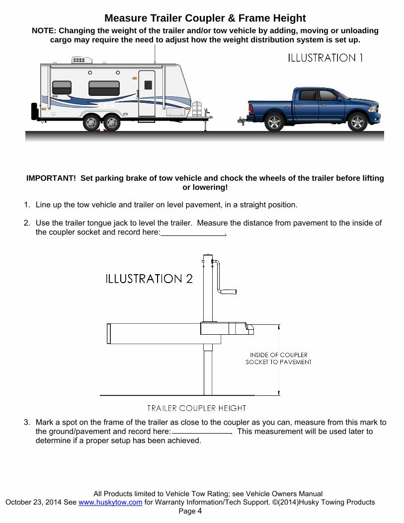
Measure Trailer Coupler & Frame Height NOTE: Changing the weight of the trailer and/or tow vehicle by adding, moving or unloading
cargo may require the need to adjust how the weight distribution system is set up.
IMPORTANT! Set parking brake of tow vehicle and chock the wheels of the trailer before lifting or lowering!
1. Line up the tow vehicle and trailer on level pavement, in a straight position.
2. Use the trailer tongue jack to level the trailer. Measure the distance from pavement to the inside of
the coupler socket and record here: .
3. Mark a spot on the frame of the trailer as close to the coupler as you can, measure from this mark to
the ground/pavement and record here: . This measurement will be used later to determine if a proper setup has been achieved.
All Products limited to Vehicle Tow Rating; see Vehicle Owners Manual October 23, 2014 See www.huskytow.com for Warranty Information/Tech Support. ©(2014)Husky Towing Products
Page 5
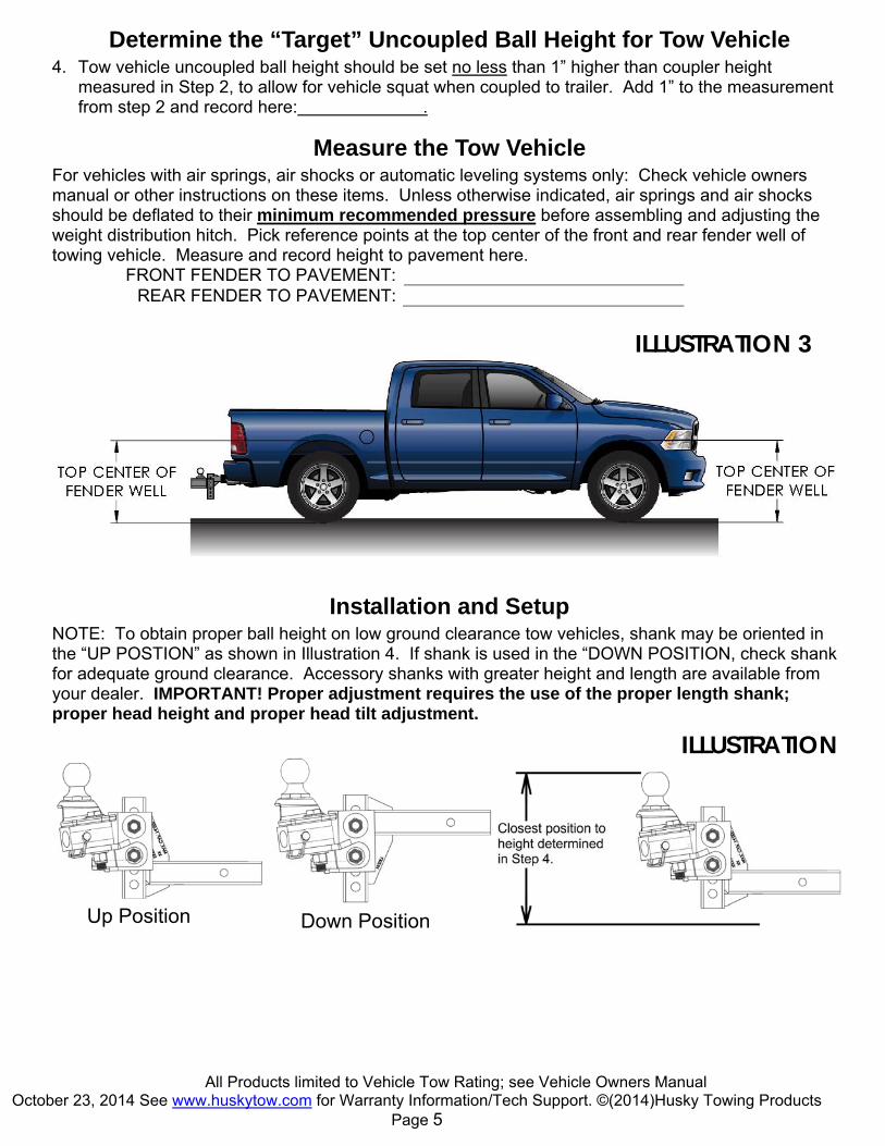
Determine the “Target” Uncoupled Ball Height for Tow Vehicle 4. Tow vehicle uncoupled ball height should be set no less than 1” higher than coupler height
measured in Step 2, to allow for vehicle squat when coupled to trailer. Add 1” to the measurement from step 2 and record here: .
Measure the Tow Vehicle For vehicles with air springs, air shocks or automatic leveling systems only: Check vehicle owners manual or other instructions on these items. Unless otherwise indicated, air springs and air shocks should be deflated to their minimum recommended pressure before assembling and adjusting the weight distribution hitch. Pick reference points at the top center of the front and rear fender well of towing vehicle. Measure and record height to pavement here.
FRONT FENDER TO PAVEMENT: REAR FENDER TO PAVEMENT:
Installation and Setup NOTE: To obtain proper ball height on low ground clearance tow vehicles, shank may be oriented in the “UP POSTION” as shown in Illustration 4. If shank is used in the “DOWN POSITION, check shank for adequate ground clearance. Accessory shanks with greater height and length are available from your dealer. IMPORTANT! Proper adjustment requires the use of the proper length shank; proper head height and proper head tilt adjustment.
ILLUSTRATION 3
ILLUSTRATION
Up Position Down Position
All Products limited to Vehicle Tow Rating; see Vehicle Owners Manual October 23, 2014 See www.huskytow.com for Warranty Information/Tech Support. ©(2014)Husky Towing Products
Page 6
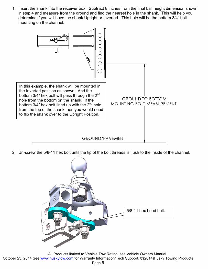
1. Insert the shank into the receiver box. Subtract 8 inches from the final ball height dimension shown in step 4 and measure from the ground and find the nearest hole in the shank. This will help you determine if you will have the shank Upright or Inverted. This hole will be the bottom 3/4” bolt mounting on the channel.
2. Un-screw the 5/8-11 hex bolt until the tip of the bolt threads is flush to the inside of the channel.
5/8-11 hex head bolt.
In this example, the shank will be mounted in the Inverted position as shown. And the bottom 3/4” hex bolt will pass through the 2nd hole from the bottom on the shank. If the bottom 3/4” hex bolt lined up with the 2nd hole from the top of the shank then you would need to flip the shank over to the Upright Position.

All Products limited to Vehicle Tow Rating; see Vehicle Owners Manual October 23, 2014 See www.huskytow.com for Warranty Information/Tech Support. ©(2014)Husky Towing Products
Page 7
3. Hold CL TS head assembly onto shank as shown and align the bottom hole on the channel to the 2nd hole from bottom on the shank and insert a 3/4” hex head bolt. Remember the hole and orientation in these instructions are an example only, yours may be different.
4. As a starting point add 3 hardened washers marked with “F436” on to the large head pin and then
insert into the welded bushing on the inside top of the channel.
3 Hardened washers and large head i
Place a 3/4” ID washer onto the 3/4” hex bolt first.
All Products limited to Vehicle Tow Rating; see Vehicle Owners Manual October 23, 2014 See www.huskytow.com for Warranty Information/Tech Support. ©(2014)Husky Towing Products
Page 8
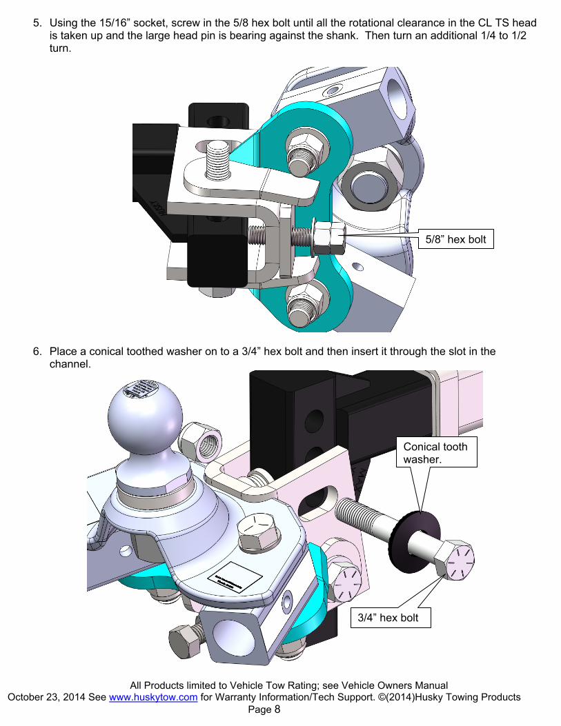
5. Using the 15/16” socket, screw in the 5/8 hex bolt until all the rotational clearance in the CL TS head is taken up and the large head pin is bearing against the shank. Then turn an additional 1/4 to 1/2 turn.
6. Place a conical toothed washer on to a 3/4” hex bolt and then insert it through the slot in the channel.
5/8” hex bolt
Conical tooth washer.
3/4” hex bolt

All Products limited to Vehicle Tow Rating; see Vehicle Owners Manual October 23, 2014 See www.huskytow.com for Warranty Information/Tech Support. ©(2014)Husky Towing Products
Page 9
7. The use of shims may be required to fill up the gap between the ears of the bottom plate weldment and the U channel. It is NOT necessary to have equal shims on either side.
8. Tighten 5/8 hex jam nut securely.
5/8 hex jam nut.
Ear of bottom plate weldment U channel
Gap
All Products limited to Vehicle Tow Rating; see Vehicle Owners Manual October 23, 2014 See www.huskytow.com for Warranty Information/Tech Support. ©(2014)Husky Towing Products
Page 10
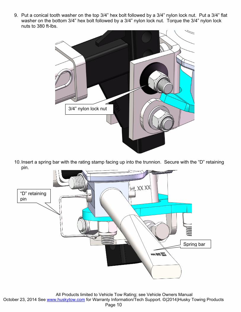
9. Put a conical tooth washer on the top 3/4” hex bolt followed by a 3/4” nylon lock nut. Put a 3/4” flat
washer on the bottom 3/4” hex bolt followed by a 3/4” nylon lock nut. Torque the 3/4” nylon lock nuts to 380 ft-lbs.
10. Insert a spring bar with the rating stamp facing up into the trunnion. Secure with the “D” retaining pin.
Spring bar
“D” retaining pin
3/4” nylon lock nut
All Products limited to Vehicle Tow Rating; see Vehicle Owners Manual October 23, 2014 See www.huskytow.com for Warranty Information/Tech Support. ©(2014)Husky Towing Products
Page 11
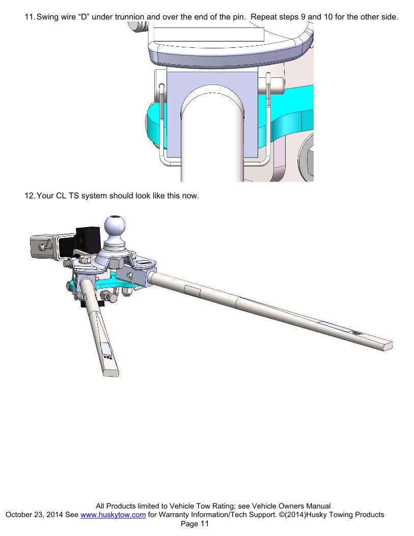
11. Swing wire “D” under trunnion and over the end of the pin. Repeat steps 9 and 10 for the other side.
12. Your CL TS system should look like this now.

All Products limited to Vehicle Tow Rating; see Vehicle Owners Manual October 23, 2014 See www.huskytow.com for Warranty Information/Tech Support. ©(2014)Husky Towing Products
Page 12
Installing Frame Brackets 13. Install frame bracket 28.5”-30.5” from center of ball socket on coupler.
28.5”-30.5”

All Products limited to Vehicle Tow Rating; see Vehicle Owners Manual October 23, 2014 See www.huskytow.com for Warranty Information/Tech Support. ©(2014)Husky Towing Products
Page 13
14. Loosen the 5/8” dog point screws so the lift bracket can be removed from the frame bracket. Use the 1/2” carriage head bolt, flat washer, lock washer and hex nut to hold the frame brackets in place. The bottom carriage head bolt should be in the hole closest to the underside of the frame.
5/8” dog point screw.
1/2” carriage head bolt.
1/2” flat washer, lock washer & hex nut.
1/2” carriage head bolt.
The frame and lift brackets can be mounted on either the driver side or passenger side of the trailer and MUST be mounted to the trailer frame as shown. DO NOT mount the frame brackets to the inside of the frame!
Trailer frame
Frame bracket
Lift Bracket
Frame Mounting Plate
Spring bar support surface
All Products limited to Vehicle Tow Rating; see Vehicle Owners Manual October 23, 2014 See www.huskytow.com for Warranty Information/Tech Support. ©(2014)Husky Towing Products
Page 14
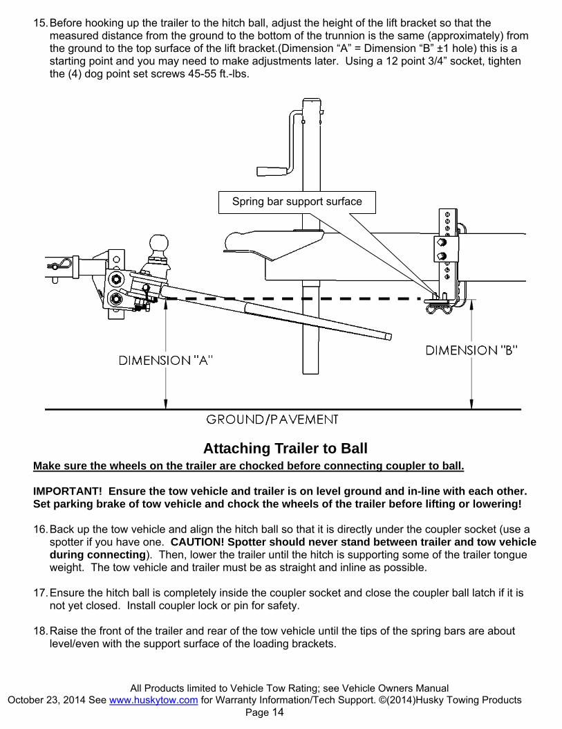
15. Before hooking up the trailer to the hitch ball, adjust the height of the lift bracket so that the measured distance from the ground to the bottom of the trunnion is the same (approximately) from the ground to the top surface of the lift bracket.(Dimension “A” = Dimension “B” ±1 hole) this is a starting point and you may need to make adjustments later. Using a 12 point 3/4” socket, tighten the (4) dog point set screws 45-55 ft.-lbs.
Attaching Trailer to Ball Make sure the wheels on the trailer are chocked before connecting coupler to ball. IMPORTANT! Ensure the tow vehicle and trailer is on level ground and in-line with each other. Set parking brake of tow vehicle and chock the wheels of the trailer before lifting or lowering! 16. Back up the tow vehicle and align the hitch ball so that it is directly under the coupler socket (use a
spotter if you have one. CAUTION! Spotter should never stand between trailer and tow vehicle during connecting). Then, lower the trailer until the hitch is supporting some of the trailer tongue weight. The tow vehicle and trailer must be as straight and inline as possible.
17. Ensure the hitch ball is completely inside the coupler socket and close the coupler ball latch if it is not yet closed. Install coupler lock or pin for safety.
18. Raise the front of the trailer and rear of the tow vehicle until the tips of the spring bars are about
level/even with the support surface of the loading brackets.
Spring bar support surface
All Products limited to Vehicle Tow Rating; see Vehicle Owners Manual October 23, 2014 See www.huskytow.com for Warranty Information/Tech Support. ©(2014)Husky Towing Products
Page 15
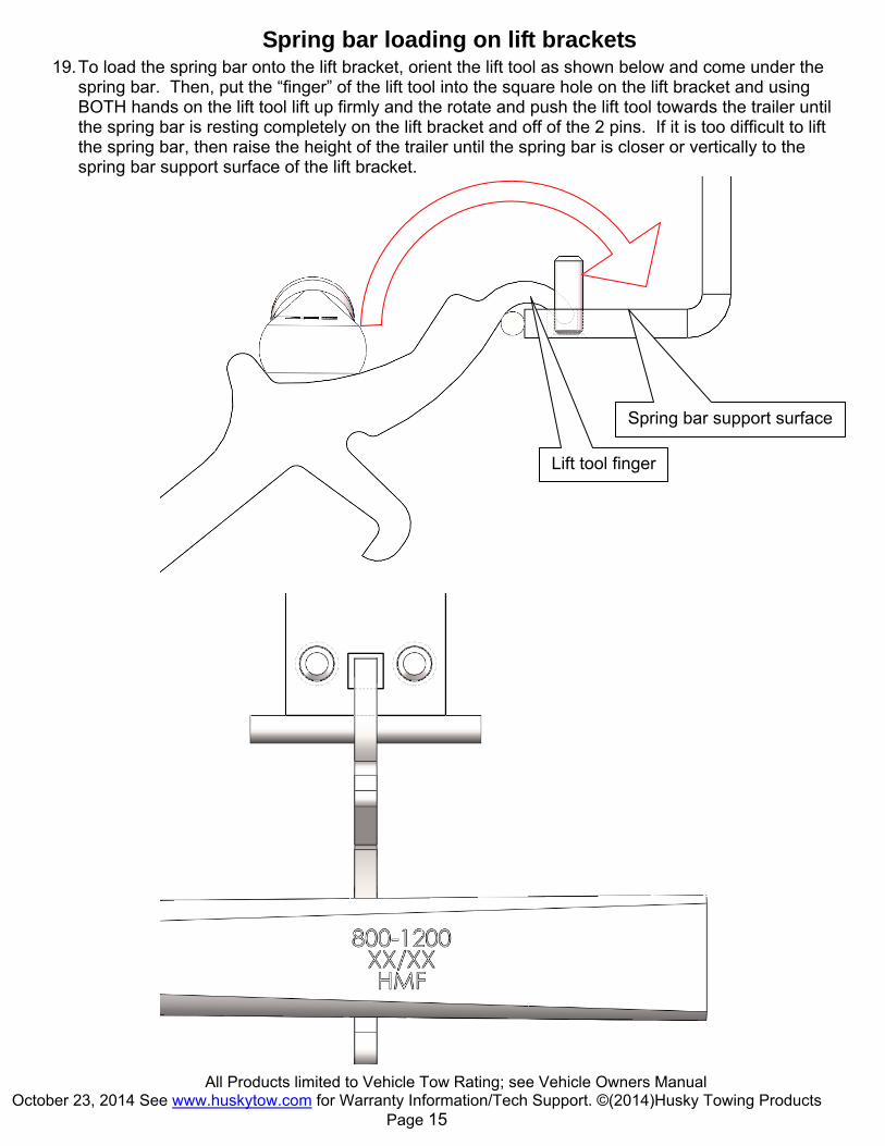
Spring bar loading on lift brackets 19. To load the spring bar onto the lift bracket, orient the lift tool as shown below and come under the
spring bar. Then, put the “finger” of the lift tool into the square hole on the lift bracket and using BOTH hands on the lift tool lift up firmly and the rotate and push the lift tool towards the trailer until the spring bar is resting completely on the lift bracket and off of the 2 pins. If it is too difficult to lift the spring bar, then raise the height of the trailer until the spring bar is closer or vertically to the spring bar support surface of the lift bracket.
Lift tool finger
Spring bar support surface

All Products limited to Vehicle Tow Rating; see Vehicle Owners Manual October 23, 2014 See www.huskytow.com for Warranty Information/Tech Support. ©(2014)Husky Towing Products
Page 16
20. Once the spring bar is resting securely on the lift bracket insert the “L” retaining pin into the square hole and secure with the hair pin clip.
WARNING: Keep clear of the pivot path of all moving parts when there is tension on the spring bar. Maintain control of the lift handle at all times when raising or lowering the spring bar. Be sure that the “L” pin and hair pin is in place before driving.
Check Vehicle Height and Adjust Spring Bars If Necessary 21. Retract the tongue jack completely so the hitch is supporting the weight of the trailer. Measure the
same 3 places as done on pages 4 & 5 and compare. The tow vehicle should settle evenly front to back. The rear fender should not settle lower than the front fender, if it has then you will need to either raise the lift brackets 1 hole or add a hardened washer under the large head tilt pin on the head assembly. The frame mark should be ¼”-1” max higher than the original measurement noted on page 4, section 3.

All Products limited to Vehicle Tow Rating; see Vehicle Owners Manual October 23, 2014 See www.huskytow.com for Warranty Information/Tech Support. ©(2014)Husky Towing Products
Page 17
Properly Adjusted System
Over Adjusted System
Under Adjusted System
Removing the spring bar from the lift bracket 22. Make sure the tow vehicle and the trailer are on level ground and are straight. Chock the trailer
wheels, and engage the emergency brake on the tow vehicle. 23. Raise the trailer tongue sufficient to ease the force required to lift the spring bar ends off of the lift
brackets. Place the lift tool on the round peg and under the end of the spring bar as shown. And start pushing down on the lift tool.
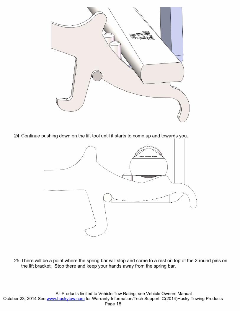
All Products limited to Vehicle Tow Rating; see Vehicle Owners Manual October 23, 2014 See www.huskytow.com for Warranty Information/Tech Support. ©(2014)Husky Towing Products
Page 18
24. Continue pushing down on the lift tool until it starts to come up and towards you.
25. There will be a point where the spring bar will stop and come to a rest on top of the 2 round pins on the lift bracket. Stop there and keep your hands away from the spring bar.
All Products limited to Vehicle Tow Rating; see Vehicle Owners Manual October 23, 2014 See www.huskytow.com for Warranty Information/Tech Support. ©(2014)Husky Towing Products
Page 19
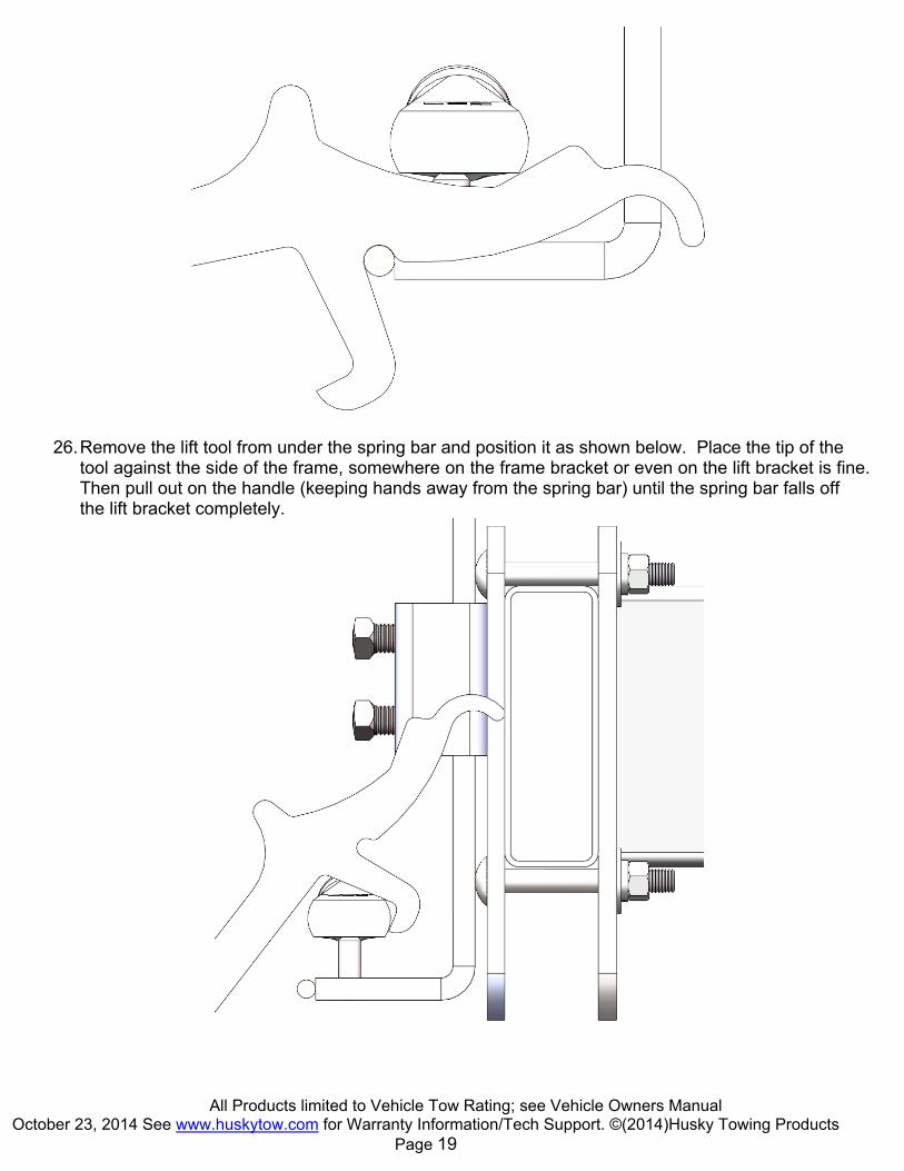
26. Remove the lift tool from under the spring bar and position it as shown below. Place the tip of the
tool against the side of the frame, somewhere on the frame bracket or even on the lift bracket is fine. Then pull out on the handle (keeping hands away from the spring bar) until the spring bar falls off the lift bracket completely.

All Products limited to Vehicle Tow Rating; see Vehicle Owners Manual October 23, 2014 See www.huskytow.com for Warranty Information/Tech Support. ©(2014)Husky Towing Products
Page 20
Parts Listing

All Products limited to Vehicle Tow Rating; see Vehicle Owners Manual October 23, 2014 See www.huskytow.com for Warranty Information/Tech Support. ©(2014)Husky Towing Products
Page 21
CE
NT
ER
LIN
E T
S, 4
00
-60
0 L
BS
. W/2
" B
AL
L
CE
NT
ER
LIN
E T
S, 4
00
-60
0 L
BS
. W/2
-5/1
6"
BA
LL
CE
NT
ER
LIN
E T
S, 6
00
-80
0 L
BS
. W/2
-5/1
6"
BA
LL
CE
NT
ER
LIN
E T
S, 8
00
-12
00
LB
S. W
/2-5
/16
" B
AL
L
HE
AD
KIT
80
0-1
20
0 L
BS
. SP
RIN
G B
AR
KIT
60
0-8
00
LB
S. S
PR
ING
BA
R K
IT
40
0-6
00
LB
S. S
PR
ING
BA
R K
IT
LE
FT
& R
IGH
T T
RU
NN
ION
, BO
LT
HA
RD
WA
RE
& D
PIN
KIT
FR
AM
E B
RA
CK
ET
KIT
LIF
T T
OO
L K
IT
SP
RIN
G B
AR
RE
TA
ININ
G P
IN K
IT
BA
LL
PL
AT
FO
RM
KIT
LA
NY
AR
D A
SS
Y K
IT
SH
IM K
IT
DO
G P
OIN
T S
CR
EW
KIT
HA
RD
WA
RE
KIT
5/8
BO
LT
, NU
T A
ND
WA
SH
ER
KIT
32
21
5
32
21
6
32
21
7
32
21
8
32
32
8
32
32
9
32
33
0
32
33
1
32
33
2
32
33
3
32
33
4
32
33
5
32
33
6
32
33
7
32
33
8
32
33
9
32
34
0
32
34
2
ITEM NO.
DESCRIPTION QT
Y
QT
Y
QT
Y
QT
Y
QT
Y
QT
Y
QT
Y
QT
Y
QT
Y
QT
Y
QT
Y
QT
Y
QT
Y
QT
Y
QT
Y
QT
Y
QT
Y
QT
Y
1 TOP PLATE AND CHANNEL WELDMENT 1 1 1 1 1 - - - - - - - - - - - - -
2 LOWER PLATE WELDMENT 1 1 1 1 1 - - - - - - - - - - - - -
3 MACHINED TRUNNION 2 2 2 2 2 - - - 2 - - - - - - - - -
4 3/4-10 X 4.5" HEX BOLT 2 2 2 2 2 - - - 2 - - - - - - - - -
5 3/4" ID FLAT WASHER 2 2 2 2 - - - - - - - - - - - - 2 -
6 5/8-11 X 2.75" HEX BOLT 1 1 1 1 1 - - - - - - - - - - - - 1
7 5/8" ID FLAT WASHER 1 1 1 1 1 - - - - - - - - - - - - 1
8 5/8 -11 HEX NUT 1 1 1 1 1 - - - - - - - - - - - - 1
9 3/8" "D" LOCK PIN ASSEMBLY 2 2 2 2 - - - - 2 - - 2 - - - - - -
10 2-5/16" HITCH BALL ASSEMBLY - 1 1 1 - - - - - - - - - - - - - -
10 2" HITCH BALL ASSEMBLY 1 - - - - - - - - - - - - - - - - -
11 BALL PLATFORM BUSHING FOR 1-1/4" O.D. SHANK ONLY 1 1 1 1 - - - - - - - - 1 - - - - -
12 LIFT TOOL ASSEMBLY 1 1 1 1 - - - - - - 1 - - - - - - -
13 SHANK, 5-1/2" RISE, 1-1/4" DROP, 7-3/4" LONG, 2" SQ. 1 1 1 1 - - - - - - - - - - - - - -
14 STUD, LARGE HEAD 1 1 1 1 - - - - - - - - - - - - 1 -
15 3/4-10 X 5" GRADE 8 HEX BOLT 2 2 2 2 - - - - - - - - - - - - 2 -
16 3/4" ID CONICAL TOOTH WASHER 4 4 4 4 2 - - - 2 - - - - - - - 2 -
17 3/4-10 NYLON LOCK NUT 4 4 4 4 2 - - - 2 - - - - - - - 2 -
18 FRAME MOUNTING PLATE 2 2 2 2 - - - - - 2 - - - - - - - -
19 1/2-13 HEX NUT 4 4 4 4 - - - - - 4 - - - - - - - -
20 1/2" ID FLAT WASHER 4 4 4 4 - - - - - 4 - - - - - - - -
21 1/2" ID HD FLAT WASHER 4 4 4 4 - - - - - 4 - - - - - - - -
22 1/2-13 X 4" CARRIAGE HEAD BOLT 4 4 4 4 - - - - - 4 - - - - - - - -
23 FRAME MOUNTING BRACKET 2 2 2 2 - - - - - 2 - - - - - - - -
24 DS\PS WDS LIFT BRACKET WELDMENT 2 2 2 2 - - - - - 2 - - - - - - - -
25 "L" PIN & WASHER LANYARD ASSY 2 2 2 2 - - - - - 2 - - - 2 - - - -
26 5/8" HAIR PIN 3 3 3 3 - - - - - 2 - - - - - - 3 -
27 5/8-11 X 2.00" SQ. HD SET SCREW W/FULL DOG POINT 4 4 4 4 - - - - - 4 - - - - - 4 - -
28 800-1200 STRAIGHT ROUND SPRING BAR W/LABELS - - - 2 - 1 - - - - - - - - - - - -
28 600-800 STRAIGHT ROUND SPRING BAR W/LABELS - - 2 - - - 1 - - - - - - - - - - -
28 400-600 STRAIGHT ROUND SPRING BAR W/LABELS 2 2 - - - - - 1 - - - - - - - - - -
29 1/2" ID HARDENED FLAT WASHER 4 4 4 4 - - - - - - - - - - - - 4 -
30 5/8" HITCH PIN 1 1 1 1 - - - - - - - - - - - - 1 -
31 HOOK SHIM 6 6 6 6 - - - - - - - - - - 6 - 6 -
32 3/4" ID HARDENED FLAT WASHER 2 2 2 2 2 - - - 2 - - - - - - - - -
All Products limited to Vehicle Tow Rating; see Vehicle Owners Manual October 23, 2014 See www.huskytow.com for Warranty Information/Tech Support. ©(2014)Husky Towing Products
Page 22
Towing Tips
Driving Tow Vehicle Good habits for normal driving need extra emphasis when towing a trailer. The additional weight of the trailer affects acceleration and braking. Extra time should be allowed for passing, stopping and changing lanes. Signal well in advance of a maneuver to let other drivers know your intentions. Severe bumps and badly undulating roads can damage your towing vehicle, hitch and trailer, and should be negotiated at a slow, steady speed. If any part of your towing system “bottoms out” or if you suspect damage may have occurred in any other way, pull over and make a thorough inspection. Correct any problems before resuming travel. Turning and backing up present new problems-plan ahead. It is highly recommended that a spotter be used when backing up to alert the driver of possible obstacles and prevent jack knifing the trailer. Towing a trailer will change your turning radius, the longer the trailer the larger radius turn.
Driving Conditions When driving in conditions where the pavement is wet, icy, snowy, loose gravel, grass and dirt, reduce speed and do not make any sudden maneuvers. Allow ample distance/time for stopping and changing lanes. If possible, wait for road conditions to improve before driving. Follow all state, local and provincial driving and towing laws in the location you are driving in. Not following your tow vehicle, trailer, and Husky instructions/manuals can result in a fatal accident.
Sway Control The CL TS system has an integrated sway control feature; do not add a secondary sway control.
Check Your Equipment Please refer to the MAINTENANCE section. Periodically check the condition of all your towing equipment and keep it in top condition.
Trailer Loading Proper trailer loading is very important. Heavy items should be placed close to the floor near the trailer axle centerline. The load should be balanced side to side and firmly secured in the trailer to prevent shifting. Tongue weight should be 10-15% of the gross trailer weight for most trailers. Too low a tongue weight often produces tendency to sway.
Tire Inflation Unless specified otherwise by the towing vehicle or trailer manufacturer, tires should be inflated to their manufacturer’s towing recommendations.
Towing Vehicle and Trailer Manufacturers Recommendations Review the owner’s manual for your towing vehicle and trailer for specific recommendations, capacities and requirements.
Passengers in Trailers Trailers should not be occupied while being towed. Most states enforce this regulation.

All Products limited to Vehicle Tow Rating; see Vehicle Owners Manual October 23, 2014 See www.huskytow.com for Warranty Information/Tech Support. ©(2014)Husky Towing Products
Page 23
Trailer Lights, Turn Signals, Electric Brakes Always hook up all of the trailer lights, electric brakes and break-away switch connection whenever trailer is being towed. Also periodically check functionality of all lights before towing and repair any problems as needed.
Remove Hitch When Not Towing Remove hitch from receiver on towing vehicle when not towing a trailer to reduce chances of striking hitch on driveway or other objects, and reduce the chance of parts being stolen.
Modifications Do not adapt or modify the Bolt Together Weight Distribution System in any way.
Safety Chains Can Prevent Runaway Trailer in case hitch/coupler fails.
1. Always use safety chains when towing. 2. Cross safety chains under coupling to prevent tongue from dropping to ground. 3. Allow only enough slack for tight turns. 4. Do not let safety chains drag on ground. 5. Twist safety chains equally from hook ends to take up slack. 6. Use safety chains rated equal to or greater than twice the maximum gross trailer weight rating.
Uncontrolled tilting of trailer can result in personal injury or equipment damage.
1. Distribute weight so that trailer tongue weight is approximately 10-15% of the gross trailer weight.
Incorrect tongue weight can cause fishtailing and loss of control of towing vehicle resulting in serious injury and equipment damage.
2. Tongue weight is the amount of trailer weight that rests on the towing vehicle hitch − that is, the downward pressure on the coupler.
3. Remove or adjust trailer load to get correct tongue weight. 4. Do not let tongue weight exceed coupler and hitch rating. 5. Use slower speeds when towing a trailer.

All Products limited to Vehicle Tow Rating; see Vehicle Owners Manual October 23, 2014 See www.huskytow.com for Warranty Information/Tech Support. ©(2014)Husky Towing Products
Page 24
Maintenance Keep hitch parts painted to prevent rust and maintain good appearance. Do not remove or paint over labels. Keep lift brackets clean, and using a light lubrication on the lift bracket support surfaces to keep rust to a minimum is acceptable.
At The Beginning of Every Towing Day: Clean ball and coupler socket and coat ball lightly with grease. Ensure the “L” pins are secured in place on the lift brackets Ensure the “D” pins are securing the spring bars in the trunnions by giving the spring bars a tug
before lifting into the lift brackets. Check that the hitch pin is in place and secure. Check frame bracket bolts are tight. Ensure the coupler latch is closed and locked with a pin. If electric brakes are used ensure the emergency break away cable is attached to the tow
vehicle. Check to see that all electrical hook-ups are in working order and that the safety chains are
securely connected. Towing safely is the responsibility of the driver of the vehicle. Failure to tow safely can result in
vehicle damage, bodily injury or death. The 3/4” trunnion hex bolts come lubricated from the factory re-lubricate if needed with
bearing/axle grease. Do not apply lubrication to the friction surfaces of the top and bottom plates or on the top or bottom trunnion surfaces as this will reduce the built in friction sway feature.
After 500 miles:
Inspect all hardware for severe wear, replace and/or torque to factory specifications when needed.
Check the tightness of the 3/4” trunnion hex bolts with a torque wrench. The torque is 150 ft. lbs. Inspect hitch ball for severe wear and ensure the hitch ball nut is torqued properly. Check to see that all shank bolts are properly tightened (380 ft. lbs.) Inspect spring bars for severe wear and there is no noticeable damage. If in doubt as to whether or not wear is beyond a safe limit always call the Husky Tow Technical
support line and discuss with a trained technical advisor.
Check All Trailer to Towing Vehicle Connections for Security and Operation NOTE: Surge brakes usually require a small amount of fore and aft movement for their actuating mechanism to function. Tighten the two ¾” bolts to 380 ft. lbs. torque once the head angle is set. Those surge brake actuators not designed for use with a weight distributing hitch may bind and not operate freely. Check your surge brake operating instructions for any specific requirements regarding their use with weight distributing hitches.
Warnings Loaded ball height should never be greater than what these instructions allow! Front wheel overload and loss of rear wheel traction can result and can lead to unstable handling. It can reduce braking ability and create a tendency to “jackknife” when turning and braking at the same time. Loss of steering may result in a “high nose” trailer setup. If this occurs refer to page 10 “CHECK VEHICLE HEIGHT AND ADJUST SPRING BARS IF NECESSARY” and make the necessary equipment adjustment or tow vehicle and/or trailer load adjustments.
All Products limited to Vehicle Tow Rating; see Vehicle Owners Manual October 23, 2014 See www.huskytow.com for Warranty Information/Tech Support. ©(2014)Husky Towing Products
Page 25
Short wheel base vehicles may induce sway when towing a trailer. USE EXTREME CAUTION. Caution: FRONT WHEEL DRIVE VEHICLES: Do not attempt to hook-up or tow with the rear tires of the towing vehicle removed. Severe structural damage to the towing vehicle, hitch and trailer may result. A towing vehicle/trailer combination cannot be controlled adequately unless the towing vehicle’s rear wheels are carrying their share of the load. CAUTION! Using the Bolt Together Weight Distribution System without the spring bars removes all weight distribution functionality of the product.

All Products limited to Vehicle Tow Rating; see Vehicle Owners Manual October 23, 2014 See www.huskytow.com for Warranty Information/Tech Support. ©(2014)Husky Towing Products
Page 26
Warranty Terms: Life Time Limited Warranty: This warranty applies solely to Husky Weight Distributing Hitch manufactured by DTS Manufacturing for Husky Towing Products. DTS Manufacturing, Husky Towing Products and Coast Distribution make no guarantees or warranties for products not manufactured by DTS Manufacturing. Such products are covered solely under any applicable warranty of the manufacturer. It is always recommended that the operating instructions and guarantee instructions provided by the manufacturer are followed. DTS Manufacturing warrants its products to be free from manufacturing and material defects to the original purchaser for the length of warranty stated above from the date of retail purchase. If any products are found to have a manufacturing or material defect, the product will be replaced or repaired at the option of DTS Manufacturing, Husky Towing Products and Coast Distribution with proof of purchase by the original purchaser. The original purchaser shall pay all transportation and shipping costs associated with the return of the defective product and the defective product shall become the property of DTS Manufacturing. The Warranty applies to DTS manufactured products used for individual and recreational purposes. Commercial usage of the DTS manufactured products limits the warranty to 90-days from date of purchase. The Warranty applies only to DTS manufactured products which are found to be defective in manufacturing or material. This warranty does not apply to normal wear and tear of to the finished placed on DTS manufactured products. DTS Manufacturing, Husky Towing Products and Coast Distribution are not responsible for any labor costs incurred for removal or replacement of the defective product. DTS Manufacturing, Husky Towing Products and Coast Distribution are not responsible for repair or replacement of any product under the limited warranty where the product was improperly installed, misapplied, altered, abused, neglected, overloaded, misused or damaged as a result of an accident, including any use of the product not in accordance with all product operating and safety instructions. Without limiting the generality of the foregoing, DTS Manufacturing, Husky Towing Products and Coast Distribution shall under no circumstances be liable for any incidental or consequential loss or damage whatsoever arising out of, or in any way relating to any such breach of warranty or claimed defect in, or non-performance of the products. Some states do not allow the exclusion or limitation of incidental or consequential damages, so the above exclusion or limitation may not apply to you. This limited warranty gives you specific legal rights, and you may also have other rights that vary from state to state.