abstract - chandra x-ray observatory (cxc)cxc.harvard.edu/cda/spie/mkahan2001.pdfacis door mechanism...
TRANSCRIPT

ACIS Door Failure Investigation: Technical Details and Mitigation Procedures
Mark A. Kahan Neil L. Tice , William A. Podgorski Paul P. Plucinsky , & Keith B. Doyle *
Abstract
NASA's Chandra X-ray Observatory (formerly AXAF) was launched on July 23, 1999 and is currently in orbitperforming scientific studies. Chandra is the third of NASA's Great Observatories to be launched, following theHubble Space Telescope and the Compton Gamma Ray Observatory. One of four primary scienceinstruments on Chandra, and one of only two focal plane instruments, is the Advanced CCD ImagingSpectrometer, or ACIS. The ACIS focal plane and Optical Blocking Filter (OBF) needed to be launched undervacuum, so a tightly sealed, functioning door and venting subsystem were implemented. The door was openedtwo and one-half weeks after launch (after most out-gassing of composite materials) and allowed X-rays to beimaged by the ACIS CCD's in the focal plane. A failure of this door to open on-orbit would have eliminated allACIS capabilities, severely degrading mission science. During the final pre-flight thermal-vacuum test of thefully integrated Chandra Observatory at TRW, the ACIS door failed to open when commanded to do so. Thispaper provides a somewhat technically expanded description of the efforts, under considerable time pressure,by NASA, its contractors and outside review teams to investigate the failure and to develop modified hardwareand procedures which would correct the problem. Although, despite considerable effort, the root cause of thetest failure was never explicitly identified, the expanded technical information and factors presented here mayprove of use to others working the details of door design. On ACIS our efforts ultimately became focussed onhardware and procedures designed to mitigate the effects of the potential, but unproven, failure modes. Wedescribe a frequent real-world engineering situation in which one must proceed on the best basis possible inthe absence of a complete set of facts.
Introduction
The Advanced CCD Imaging Spectrometer (ACIS) is one of the four primary science instruments on theChandra (formerly AXAF) X-ray Observatory and one of only two focal plane instruments. A picture of theACIS instrument is shown in Figure 1 . In this view, the X-rays would be imaged by the X-ray mirrors, locatedfar above the instrument, and directed downwards into the detector housing, where the CCD imaging chips arelocated. The ACIS door is shown in the open position in the picture. Due to the presence of a fragile opticalblocking filter over the CCD's and the need for extreme cleanliness, the ACIS focal plane must be kept in anevacuated detector housing and launched under vacuum. The blocking filter essentially "blocks" any visible orultraviolet light from entering ACIS's aperture. Acoustic loading during the launch environment due to presenceof air in the detector housing would destroy the delicate filters. The ACIS door seals the detector housingduring ground operations leading up to launch. STARSYSTM paraffin (wax) actuators are used as componentsin a rotary actuator, to open and close the door for ground testing and on-orbit operations.
The ACIS door mechanism, designed and built by Lockheed-Martin Co., was fully qualified and life tested (onan engineering model) and the flight unit had been actuated at least 23 times during component testing andduring system assembly and test operations. However, during the final Chandra Observatory levelthermal/vacuum test at TRW, the door failed to open when commanded to do so. This failure occurred in Juneof 1998, at a time when the Chandra launch was scheduled for early CY 1999. A similar failure of the door toopen on-orbit would eliminate the use of the ACIS instrument and thereby greatly degrade mission sciencecapabilities.
Needless to say, this failure at such a critical time in the Chandra Integration and Test cycle was extremelydistressing and generated an immediate, overwhelming and ultimately successful response from a combinedteam of NASA-MSFC, contractor and independent review team person ne112.* The work at Optical Research Associates was performed under ADF contract 97-6135.** The work at Lockheed-Martin was performed under MIT contract SC-A-I 24624.*** This work was supported at SAO by NASA Chandra contract NAS8-39073.
Optomechanical Engineering 2000, Mark A. Kahan, Editor,Proceedings of SPIE Vol. 4198 (2001) © 2001 SPIE · 0277-786X/01/$15.00186
Downloaded from SPIE Digital Library on 09 Sep 2010 to 128.103.149.52. Terms of Use: http://spiedl.org/terms

Figure 1 ACIS Instrument
Proc. SPIE Vol. 4198 187
Downloaded from SPIE Digital Library on 09 Sep 2010 to 128.103.149.52. Terms of Use: http://spiedl.org/terms

ACIS Door Mechanism Design
Design Requirements
The design of the ACIS Detector Assembly was performed by Lockheed-Martin Astronautics under contract toMIT (contract # SC-A-124624), who in turn was under contract to NASA-MSFC for the ACIS Instrument.Design work started in 1994 with a prototype unit built prior to Preliminary Design Review (PDR). Aqualification unit was built and tested in early 1995 with the flight build and test starting in early 1996. AnEngineering Unit was also built and was delivered to MIT in early 1995. There were many requirementswhich contributed to the final design of the ACIS Detector Assembly Door Mechanism. The key ACIS doorrequirements are listed below:
I . Design Life 253 Cycles2. Operating Temperature Range -60°C to +45°C (Qualification)3. Flight Operating Temperature 20°C4. Survival Temperature Range -76°C to +45°C5. Operating/non-operating Pressure 800 TORR to 0 TORR6. Operating Voltage Range 24 Volts DC to 36 Volts DC7. Actuator Mm. Operating Torque > 5.1 Nm (45 ln-lbs)8. Actuator Mm. Stall Torque > 6.8 Nm (60 In-Ibs)9. On-orbit Operation One open cycle10. Ground Operation < 100 CyclesI I . Cleanliness Requirements Class IOOA and meet the Requirements of
MSFC-SPEC-1238 and MIL-SPEC-144312. Internal Vacuum Up to one atm Pressure difference Across Door13. Seal Capability < I Torr leakage per Day
Contamination control was a significant design driver for the door mechanism assembly and so partingcompounds were not utilized and materials and components were selected which were known to becompatible with these requirements. The requirement for an internal vacuum (in the detector housing) for allground processing and launch environments, combined with the very low allowable leak rate for such a smallinstrument volume, demanded a nearly perfect hermetic door seal. An unlubricated Viton ® 0-ring waschosen as the sealing material because of its vacuum compatibility and low outgassing properties. The torquerequirements for the door actuator were derived from some early development tests which showed arequirement for at least 2.3 Nm (20 in-Ibs) of torque capability from the actuator when using a dry Viton 0-ring.Actuator trade studies performed early in the PDR design phase resulted in a decision to proceed with aRotary Paraffin Actuator built by STARSYS Research to drive the door mechanism open and closed. Thisactuator (Part # HL4570B), based on a design from a previous NASA program, had redundant built-in limitswitches and heaters with a positive latch at both extremes of travel. The minimum stall torque capability forthis actuator was 6.8 Nm (60 in-Ibs), which was a factor of 3 greater than required.
Door Mechanism Actuator and Linkaqe
The rotary actuator uses two linear paraffin actuators, one for each rotational direction. Upon actuation,heaters inside a cartridge warm the internal paraffin. As the paraffin changes phase at around 70°C its volumeincrease forces a steel pin outward; this linear travel is converted into rotary motion of the output shaft andcoupled ACIS torsion driveshaft. The driveshaft and a folding two-bar linkage rotate the door approximately92 degrees and out of the field of view upon opening; in the other direction the linkage is driven to a nearlystraightened locking position when the door is closed. The linkage contains an adjustable turnbuckle, set toprovide a calibrated force against the Viton 0-ring. This force, determined through development testing,provides adequate sealing for evacuation of the instrument without additional applied forces. A "swing link"supporting the door hinge axis allows the door to seat fully on the 0-ring so that 0-ring compression is uniformupon preload and evacuation. An internal shear disk in each actuator prevents excessive pressure inside theactuator from causing a catastrophic failure of the paraffin actuator cartridge & protects the other componentsin the device from damage. However, a shear disk rupture does render the actuator permanently disabled.Figure 1 shows the ACIS door mechanism in the open position, with the access cover removed and the
Proc. SPIE Vol. 4198188
Downloaded from SPIE Digital Library on 09 Sep 2010 to 128.103.149.52. Terms of Use: http://spiedl.org/terms
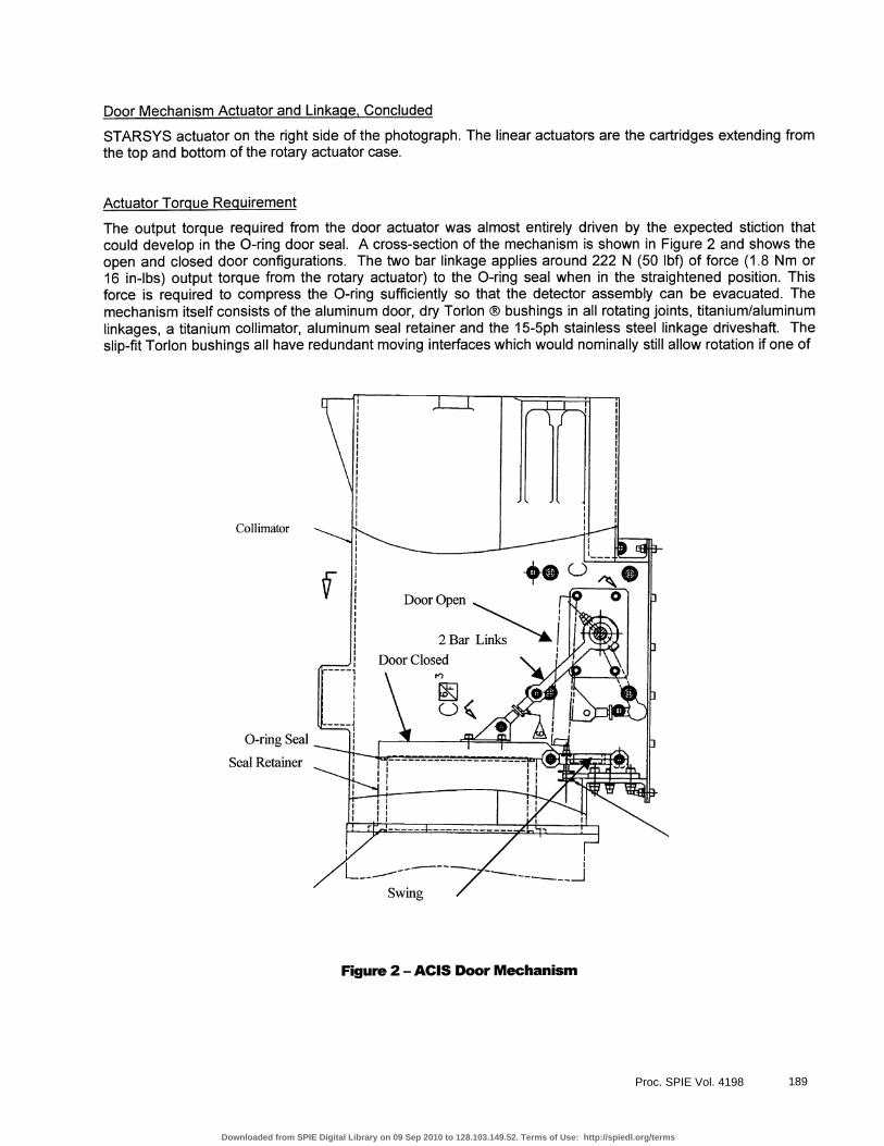
Door Mechanism Actuator and Linkage, Concluded
STARSYS actuator on the right side of the photograph. The linear actuators are the cartridges extending fromthe top and bottom of the rotary actuator case.
Actuator Torque Requirement
The output torque required from the door actuator was almost entirely driven by the expected stiction thatcould develop in the 0-ring door seal. A cross-section of the mechanism is shown in Figure 2 and shows theopen and closed door configurations. The two bar linkage applies around 222 N (50 lbf) of force (1.8 Nm or16 in-lbs) output torque from the rotary actuator) to the 0-ring seal when in the straightened position. Thisforce is required to compress the 0-ring sufficiently so that the detector assembly can be evacuated. Themechanism itself consists of the aluminum door, dry Torlon ® bushings in all rotating joints, titanium/aluminumlinkages, a titanium collimator, aluminum seal retainer and the 15-5ph stainless steel linkage driveshaft. Theslip-fit Torlon bushings all have redundant moving interfaces which would nominally still allow rotation if one of
Collimator
0-ring Seal
Seal Retainer
Figure 2 - ACIS Door Mechanism
Proc. SPIE Vol. 4198 189
Downloaded from SPIE Digital Library on 09 Sep 2010 to 128.103.149.52. Terms of Use: http://spiedl.org/terms

Actuator Torque Requirement, Concluded
the surfaces were to bind. Running torque for the mechanism was very low, even in IG environments, sincethe door weighs only about 0.1 1 kgm (025 Ibs). The total running torque for the drive train was only around0.5 Nm (4.5 in-Ibs), which was mostly the frictional and spring losses inside the rotary actuator. The frictionallosses in the Torlon bushings were minimal. Analysis and testing showed that there was not an issue withclearance changes that could result in any binding of mechanism components, even at the most extremetemperatures. Additionally (post-failure), the mechanical advantages at all joints were re-computed allowing forworst case angular positions (as loose tolerances can sometimes lead to unfavorable piece-part mechanicalpositions). This analysis showed no positions resulting in abnormal forces or restraints.
Design Redundancy
As is the case with most mechanisms or structures, the door mechanism drive train components connectingthe rotary actuator to the door (driveshaft, linkages, etc.) were not redundant. Rotation joints in all linkageswere intended to be single fault tolerant due to the inclusion of floating Torlon bushings. Adding a secondrotary actuator would have significantly complicated the mechanism. The paraffin actuators themselvescontained dual sealing 0-rings and redundant heaters. The rotary actuator also contained redundant limitswitches. Return springs inside the rotary actuator were designed to low operating stress levels to avoidredundancy concerns. During the design phase, a single paraffin actuator with redundant heaters wasdeemed to be adequate for a one-time on-orbit actuation requirement. These actuators had significant flightheritage with extremely high reliability, and required only 28 volt input power to one of the redundant heaters toperform as designed. All of the electronics required to power the actuators were fully redundant and met thesingle fault tolerance requirement.
Paraffin actuator shear disk rupture from high internal pressure was considered a potential single point failureresulting in loss of mission. During operation, the actuator reaches a temperature considerably above theparaffin melting point. If the case temperature becomes too high before heater shutoff, internal pressure isrelieved by shear disk rupture. STARSYS research data showed a disk rupture threshold temperature of154°C; the design team concluded that a shut-off of 135°C left acceptable margin for door operation, based onour development testing. To protect against failure, redundant temperature sensors were installed onto theactuator case and were monitored autonomously by the ACIS Power Supply and Mechanism Controller(PSMC). Power was removed if the actuator ever reached 133-135°C. The subject of shear disk rupture willbe discussed in more detail later in the paper.
Pre-Flight Testing
Qualification Testinq
Pre-flight testing was performed per NASA procedures to fully qualify the mechanism for flight. These testsincluded a 253 cycle thermal/vacuum mechanism life test on a special life-test unit (CAMSIM), 0-ring stictiontests, acoustic tests, and random vibration tests. Initially it was felt that there were no significant issues thatwere not addressed in the final flight design for the door mechanism. One of the minor problems addressedwas the burn-out of one of the life-cycle test heater elements. The root cause of this failure was a processchange in a Minco heater that led to a delamination of the heater and subsequent burn-out as paraffin workedits way into the heater and fatigued the element. For flight, new heaters were fabricated with the originalprocess and were re-qualified and life-cycle tested. A second problem occurred during the life-cycle test dueto I C affects and rapid cycling of the mechanism and paraffin actuators. Convection inside the hot wax (onlypresent in I G) resulted in a non-uniform re-freezing of the paraffin as it passed through the phase-changetemperature. Since the paraffin froze at the bottom of the actuator first, the actuator output pin was preventedfrom fully retracting. This problem was addressed by procedural changes, a new retraction spring which had ahigher spring constant, and an additional limit switch capability which would alert operators if the shaft was notfully retracted after a close cycle. There was a procedure in place, which never had to be used, to re-set theactuator should this problem repeat. These qualification tests showed that the mechanism was ready for flightbuild with no major design changes.
Proc. SPIE Vol. 4198190
Downloaded from SPIE Digital Library on 09 Sep 2010 to 128.103.149.52. Terms of Use: http://spiedl.org/terms

Flight Unit Testing
The flight unit Detector Assembly door was opened and closed at Lockheed-Martin at least 12 times as part ofthe component level Protoflight Test program under various test conditions prior to delivery to MIT. Testingincluded pre and post environmental exposure performance tests, random vibration tests, and thermal vacuumtests. The flight unit Detector Assembly was delivered to MIT in early 1997 and the flight focal plane andoptical blocking filters were installed in April of 1997. The door was cycled open and close I I more times insystem level testing as described below.
An ACIS system level Thermal Vacuum test of all of the flight hardware was conducted at MIT Lincoln Labs.The door was cycled two times as part of the long and short form functional testing of all ACIS hardware, athot and cold temperature extremes, with nominal results. At the completion of this test, the integrated ACISwas delivered to MSFC for an additional one month calibration test in the MSFC X-Ray Calibration Facility(XRCF) thermal/vacuum chamber. During X-ray calibration, several additional door operations cycles wereperformed under flight-like operating conditions with nominal performance. After calibration activities werecomplete, the unit was vibration tested as part of the final acceptance test by MSFC. Pre and post testmechanism performance, which included door cycling, was nominal, thus adding four more door open/closecycles. The integrated ACIS was then shipped to Ball Aerospace in Boulder for integration onto the IntegratedScience Instrument Module (ISIM). The Detector Assembly was kept under vacuum for 5 months until theISIM was fully integrated. ISIM level thermal/vacuum testing started in October 1997. During these tests thedoor was opened and closed two more times under flight-like conditions. One additional successful dooropening occurred at ambient temperature and pressure in January of 1998. The ISIM was then shipped toTRW for integration onto the Chandra telescope. Periodic pump downs of the ACIS Detector kept the internalpressure between 0 and 10 torr for all system integration and test activities (including system Acoustic test).
Related Testiq
Another STARSYS HL4570B rotary actuator (same model as for door) was used in the ACIS Large Vent Valvemechanism. A failure of this actuator occurred during the ACIS system thermal vacuum test at MIT LincolnLabs in April of 1997. This failure was due to an operator error which caused both the open and closeactuators to be powered simultaneously. Under this condition, one of the shear disks ruptured and requiredthe removal and replacement of the Large Vent Valve rotary actuator with a flight spare actuator. Correctiveaction was to follow procedures to prevent simultaneous powering of open and close actuators. The largevent valve was cycled hundreds of times during test and integration and was never an issue before or after thisevent. However, this failure on the large vent valve pointed to a potential weakness in the actuator design. Asdiscussed earlier, disk rupture will normally occur at a case temperature of about 154°C, and the PSMC willcut-off power when the actuator temperature reaches about 135°C. However, it was discovered that this154°C rupture temperature was based on a linear actuator in which the output pin is allowed to extendnormally to full extension. Therefore, the rotary actuator must operate with stall torques less than 6.8 Nm(60 In-lbs) on the rotary output shaft. if the output pin is restrained from extending, then there is no additionalvolume for the paraffin to expand into and the shear disk will rupture at a much lower temperature if power isnot removed promptly. Thus, in the case of a restrained actuator, the temperature sensors do not provideprotection from rupture except at end-of-stroke.
As it turns out, instead of a constant temperature shut-off point, each paraffin actuator could be protected by avariable shut-off temperature dependent on the amount of linear extension of its output shaft (transformed intorotary actuator shaft rotation). At zero degrees of rotation for the rotary actuator mechanism, the shut-offtemperature should have been around 90°C rising to 150°C at full rotation or end-of-stroke. However, since anormal operation of the door or large vent valve would result in an actuator temperature of I 05-1 1 0°C, wecould not simply lower the shut-off temperature without affecting the ability to operate normally. It was also toolate in the program to re-design the electronics to provide a variable shut-off temperature. It was evident,however, that in the case of a bound actuator shaft early in the stroke, we would not achieve our goal ofopening the door. This potential new protection would have allowed us to try opening the door many times
Proc. SPIE Vol. 4198 191
Downloaded from SPIE Digital Library on 09 Sep 2010 to 128.103.149.52. Terms of Use: http://spiedl.org/terms

Related Testing, Concluded
rather than just once. The decision not to implement this protection was based on our high confidence n ourability to open the door, since we had never observed a stiction torque above 2.3 Nm (20 in-lbs) in over3 years of testing.
To summarize the component and system level testing: the ACIS flight unit door was successfully cycled atleast 23 times prior to the opening attempt at TRW under various operating temperatures and pressures. TheACIS team had confidence in the door mechanism performance for system level thermal vacuum test and forflight. There had been no anomaly in any of the previous door opening attempts. In fact, closing the door hadalways been of greater concern since the door was closed against a frozen (stiff) 0-ring several times duringthese tests. Measured paraffin actuator case temperatures were always higher when closing against a frozen0-ring, but the unit was qualified to perform under these conditions so it was never an issue.
Door Opening Failure in System Thermal/Vacuum Test
Door Opening Failure
The fully integrated Chandra X-ray Observatory was subjected to over one month of thermal/vacuum testing atTRW (Chandra prime contractor). The final test planned for this period was a stray light test, in which theACIS door would be opened and the ACIS used as a sensor to measure stray light levels within the telescope(lamp banks simulating the sun were installed in the TN chamber). Test conditions prior to the stray light testwere nominal for the telescope, with the ACIS running at cold temperatures as would be normal forobservations in flight. Since there had been several past door openings with ACIS cold and a warm-up wouldhave taken extra time, it was decided to open the door in the cold condition. At the time, there was noobjection from anyone on this point.
The ACIS door opening procedure was run at 5am PDT on June 18, 1998, but the door did not open. Theinformation available at the time was as follows: 1) Door Open Actuator exceeded its power shut-offtemperature at 133°C with autonomous removal of power by the ACIS electronics (PSMC), 2) using X-raymeasurements from a door mounted calibration source, it was determined that little to no motion of the doorhad occurred, 3) STARSYS actuator limit switch operation indicated less than 20 degrees of rotation hadoccurred, 4) ice had been observed on external surfaces of the Observatory, indicating the presence of atleast some water in the TN chamber, 5) the ACIS door and camera body were at —-60°C, and 6) theSTARSYS Actuator was at -42°C at the start of the procedure.
Post-test Failure Recovery and Analysis
Initially Suspected Failure Modes
As is usual in such cases, a small "tiger" team was formed to determine an immediate course of action. Evenat this early stage, the team believed there was a high probability that the ACIS would have to be removedfrom the Observatory. A full stall of the mechanism with no door movement would more than likely haveruptured the shear disk inside the Paraffin Actuator based on experience with the Large Vent ValveMechanism. A fault tree was created to help determine possible causes of the anomaly. The final form of thefault tree is shown in Figure 3. The first three (non italicized) items were those which were initially considered.
Proc. SPIE Vol. 4198192
Downloaded from SPIE Digital Library on 09 Sep 2010 to 128.103.149.52. Terms of Use: http://spiedl.org/terms

Initially Suspected Failure Modes, Concluded
A. Door/Seal Retainer Bound. Cold weld. Ice. SealAdhesion
- Electrostatic- Djffusion- van der Waals- ChemicalBonding
B. Rotary ActuatorBoundI Parts Bound. Mismatched parts. Contamination
C. Paraffin Actuator Bound or Failed. Heater failedS Wax leak. Start low temp. Low lube
D. Rotary Actuator Shear Disk Previously RupturedE. Test Procedure not followedF. Retarding Torque > 6.8Nm (60 in-lbs.). Over-center
. Seal SeparationG. Linkages Bound
. CTE Mismatch. Bushing/Linkage bending. Ice
. Contamination
Figure 3 - ACIS Door Failure Fault Tree
Ideally, the team would have liked to see the unit left undisturbed to prevent the loss of information that couldultimately lead to determination of the failure mode. However, the MIT and Lockheed-Martin team concludedthat there was too great a risk of damage to the focal plane and OBFs from contamination if the door were notfully closed prior to re-pressurization of the chamber. The door provides a nearly hermetic seal which wouldprotect the focal plane and OBF's from contamination as the shrouds and spacecraft were warmed up and thechamber re-pressurized.
Recovery from Failure in ThermalNacuum Test
The decision was made to warm the detector assembly and door to 25°C using heaters that were designed forbaking off contamination on-orbit. To protect the instrument and get the door closed, the open actuator had tobe heated to soften the paraffin. With a warm open actuator, there was a higher probability that the closeactuator could re-set the mechanism and latch the door closed again. The procedure was performed at 7pmPDT without success. Neither the open nor the close limit switches changed state, and the close actuatorwent over-temperature at 133°C as the PSMC autonomously removed power. A nominal opening or closingwould normally result in an actuator temperature of around 105°C at limit switch shutoff. Now the questionwas whether or not the door was sufficiently sealed to allow for chamber re-pressurization. As dry nitrogenwas bled into the chamber, the differential pressure transducers on the detector assembly quickly confirmedthat the door was sealed, since a vacuum was measured within the detector housing. The focal plane andOBF were in a safe condition, since one atmosphere of pressure differential provides about 500 pounds of
Proc. SPIE Vol. 4198 193
Downloaded from SPIE Digital Library on 09 Sep 2010 to 128.103.149.52. Terms of Use: http://spiedl.org/terms

Recovery from Failure in ThermalNacuum Test, Concluded
closing force on the door. Therefore once the door sealed, a positive latch was not necessary and theinstrument could be handled safely without the fear of damage to the focal plane and OBFs.
During the next several days Chandra was removed from the chamber, the ISIM was removed from the opticalbench and partially disassembled, then the ACIS was removed for shipment back to Lockheed-Martin. Initialexternal inspections at TRW looked normal except that the door did appear to have metal to metal contact withthe seal retainer. This metal-to-metal contact could support the cold welding hypothesis but later inspectionsand testing would discount this failure mode. The ACIS detector was then shipped back to Lockheed-Martinwhere inspections and disassembly could occur in a class 100 clean room.
Initial Inspections at Lockheed-Martin
Failure investigation efforts centered on closing branches of the fault tree shown in Figure 3. Initial inspectionsof the door mechanism at Lockheed-Martin did not reveal the cause of the failure. All linkages appeared to befree and the two bar link was slightly over-center, which explained why the door was able to seal. It appearedthat the door was metal to metal with the seal retainer, but until the detector was re-pressurized, we would notknow if the door and seal were bound to one another. Since there was still a vacuum inside the detector, asmeasured with the Vacuum Ground Support Equipment (VGSE), we elected to remove the STARSYS actuatorprior to detector housing re-pressurization, so that it could be inspected independently of the rest of themechanism.
Door Seal/Retainer Bound (For the Non-Italicized Fault Tree Item A)
Since cold welding of the gold plated door to the aluminum seal retainer was a possible failure mode, extremecare was taken as the detector assembly was re-pressurized. Dial indicators were mounted above the door tomeasure movement of the door as dry nitrogen was allowed back into the camera body. The door slowly roseoff of the seal retainer as the internal pressure was equalized to the ambient pressure in the clean room. The0-ring was still compliant and relaxed as the external pressure was removed from the door. Cold weldingand/or galling was ruled out both because the 0-ring and its gland had been sized to preclude line-to-linemetal contact after a compressive set, and because the as-built 0-ring had enough spring force to push thedoor away from the seal retainer. Close inspection revealed no signs of cold welding, metal burnishing, ormetal-to-metal oxide/contaminant adhesion. This also would have been the case when the TRW thermalvacuum chamber was initially evacuated since the pressure differential across the door would been reduced ina similar manner.
With the differential pressure equalized, the door could be opened and running torque and seal adhesion couldbe measured. Using a torque wrench to drive the door open, the seal adhesion plus running torque wasmeasured to be 2.6 Nm (23 in-Ibs) which was near the expected value. Seal adhesions had never beenmeasured above 2.3 Nm (20 in-Ibs) and with a running torque of around 0.5 Nm (4 in-Ibs), the seal adhesionwas 2.2 Nm (1 9 in-Ibs). The full capability of the STARSYS actuator as measured in subsequent testing, wasaround 10.2 Nm (90 in-Ibs) which gave a factor of safety of over 4 above what was measured. With runningtorque within normal specifications, no problems were found with the mechanism. Further disassembly andinspections showed all dimensions for bushings and other components to be within specifications at roomtemperature. No binding or interference was found which could have contributed to the failure. Additionaltesting on the Torlon® bushings showed that the coefficient of thermal expansion was as expected and thatanalytically there were no concerns with the mechanism binding at low temperatures.
The over-center torque on the door mechanism was also found to be within specifications at about I .9 Nm(17 in-Ibs). Since this flight mechanism was set up in an over-center condition, due to normal rotational andmachining tolerances, there was concern that if the over-center torque was too high then it could havecombined with another failure mode to result in excessive retarding torque. This was shown not to be the casewith testing on other engineering units even for an incompressible 0-ring. Conservatively, the flight unit wasre-assembled with the mechanism adjusted in a slightly under-center condition by building a new adapterbracket.
Proc. SPIE Vol. 4198194
Downloaded from SPIE Digital Library on 09 Sep 2010 to 128.103.149.52. Terms of Use: http://spiedl.org/terms
STARSYS Actuator Inspection and Test( Fault Tree Items B and C)
Failure of the STARSYS rotary actuator was one of the failure modes identified on the fault tree. X-rayinspection of the unit did not show any anomaly. As was expected, the open actuator shear disk had ruptureddue to excessive pressures inside the actuator. The open actuator output shaft was slightly extended whichexplained why the latch and limit switches were not engaged. Some drive shaft rotation was also observed inthe X-rays of the actuator. There was no evidence of any foreign material or debris that could have jammedthe mechanism. The open actuator cartridge was then removed from the actuator assembly. As the actuatorwas removed, the latches and limit switches fell into place. The slightly extended output shaft, which wasfrozen in the paraffin, had prevented the actuator from re-setting completely. The shear disk looked like anormally ruptured disk with no signs of any material weakness. Material properties were measured for theshear disk and were as expected. There were no signs of wax leakage and internal inspections of the waxcartridge were nominal. Force measurements were made to determine the running torque for the rotarymechanism and were nominal at both room temperature and at —45°C.
Prior to total disassembly, the close actuator cartridge was removed and installed onto the open actuator sideof the rotary mechanism assembly. At STARSYS, the unit was tested to failure with a full stall to characterizethe performance of the actuator and shear disk under these conditions. This full stall test, performed at -45°C,simulated the condition where the door mechanism did not rotate and all bushings and linkages were frozensolid. The temperature profiles were similar to those which were measured at the time of the failure up untilthe actuator reached a temperature of around 129°C, at which time the shear disk ruptured. This is slightlylower than the estimated failure temperature of 132°C at TRW, but would be expected with this more severetest condition. The door mechanism linkages and torsion shaft would have allowed more rotation of the rotaryactuator and thus a higher temperature at shear disk rupture. It is interesting to note that both shear diskswere nearly protected since the PSMC shut-off temperature was set at I 33-1 35°C. The peak torque at sheardisk function was 10.4 Nm (92 in-Ibs) vs. the 6.8 Nm (60 in-lbf) specification. Material testing showed that boththe open and close shear disks were similar in thickness and shear properties, so it is likely that the STARSYSrotary actuator output was around 10.2 Nm (90 in-Ibs) at the time of the failure at TRW. Completedisassembly and inspection of the mechanism and actuators did not reveal a problem. Nothing wasobstructing the mechanism and the only discrepancy was the ruptured shear disk. This closed out numerousbranches on the fault tree since everything appeared and functioned nominally.
The shear disk rupture point varies linearly depending on the amount of extension of the actuator linear outputshaft, which can be anywhere from 0 to 19 mm. At 0 mm of linear extension, test data showed the actuatorwould reach an equivalent pressure to achieve 6.8 Nm (60 in-lbf) on the output shaft at around 90°C. Therupture temperature would be higher at an equivalent output torque of I 0.2 Nm (90 in-Ibs). For an extension of19 mm, the shear disk would rupture at an estimated 154°C. Subsequent discussions will show that webelieve the flight unit shear disk ruptured at around I 32°C which also supports the evidence that the doormechanism had rotated 20-25 degrees (5.7 mm of linear extension) at the time of failure and was not lockedup. The clearances in the bushings and the windup in the mechanism components could allow the actuatorlinear output pin to extend as much as 5.7 mm even with a stuck door.
NASMndustry Team Formation and Failure Investigation Approach
Failure Investigation Team
The small team of Lockheed-Martin, NASA-MSFC and STARSYS personnel as discussed above initiated doormechanism failure diagnostics. Their goal was to determine the cause of the failure, fix the problem, and thenreturn the ACIS detector to flight configuration so that it could be reinstalled on Chandra and still meet the(then projected) January 1999 launch schedule. This team was initially given two weeks to complete theseactivities, based on the (optimistic) assumption that the failure mechanism would be easily identified andrectified. As it eventually became clear that the failure was not going to be quickly resolved, NASA-MSFCformed a larger ACIS Door "Tiger" team which included members from NASA-MSFC, selected members theChandra External Independent Readiness Review (EIRR) Board (from Optical Research Associates & theAerospace Corporation), MIT, Lockheed-Martin, STARSYS, TRW and SAO. The team's function was tooversee and facilitate the ongoing ACIS door failure investigation and the decision making process. In the end,the team was to operate for almost one year, as circumstances dictated, with weekly telecons and meetings asnecessary.
Proc. SPIE Vol. 4198 195
Downloaded from SPIE Digital Library on 09 Sep 2010 to 128.103.149.52. Terms of Use: http://spiedl.org/terms

Failure Investigation Team, Concluded
The situation at the time the larger team was formed, in early July 1998, was not a promising one. Asdescribed above, initial work by the smaller team had ruled out many of the proposed failure mechanisms.Also, program schedule pressure was large, even though the launch date had been slipped to mid-summer1999 due to other factors. The expanded team, along with senior NASA and program management, decided topursue parallel paths of off-line failure investigation along with the re-build and re-test of the ACIS detector andthen re-integration with the Chandra Observatory. It was believed that the re-test effort would also supplyvaluable data to the failure investigation team. As a further backup possibility, NASA-MSFC even developedan alternate actuator that could have been substituted into ACIS should subsequent problems with the abovepaths occur downstream closer to launch.
With more resources available now, many activities could proceed in parallel, even though the primary activityremained at Lockheed-Martin. These activities included the expansion of the fault tree to include a moredetailed examination of the italicized items some of which were not initially considered, further investigationinto the issue of ice formation, more detailed investigations into the stiction properties of Viton, a search of theprior test data to look for a possible inadvertent powering of the door actuator, development of a detailed finiteelement model of the door mechanism and 0-ring to provide additional design verification and, of course, there-build of the flight ACIS detector for a re-test at TRW in August of I 998.
Further Failure Investigations (Italicized Items, SectionA, Figure 3), Changes, and Launch Liens
The expanded review team briefly reinvestigated a large number of fault tree branches that had beenpreviously closed by analysis, test, and inspection. Possibilities reviewed included considerations that slowvoltage ramp-ups in testing could have inadvertently produced a condition that might burst an actuator, as wellas microscopic effects of ice/water, &/or Viton cold-flow. Additional tests and analyses were conducted in eachof these areas, and selected design and operational changes were made to address each open fault treebranch. Mitigation schemes were implemented and verified by tests &/or FEM techniques including: (a) theuse of a controlled energy slug and potentiometer to allow multiple opportunities to open the door on-orbit(reducing any paraffin actuator shear disk operational risk), (b) the previously noted elimination of "over-center" torque so as provide additional margin, and (c) use of door grounding to eliminate concerns relative toany stiction induced by electrostatic forces. Although a few KV were initially computed (given an Ion 55 sourcewhich was attached to the door for later use in on-station telescope calibrations), this value was later reducedto low levels as both further analysis and testing showed that the small gap at the seal interface can't supporta significant level of charge build up. Regardless, the grounding strap was added for safety.
It was believed that a warm door opening on-orbit would close all open fault tree branches, but a launchconstraint was imposed requiring a successful KSC open/close cycle. Further, an additional defacto launchconstraint was imposed which required successful Engineering Unit testing using flight-like timelines for doorclosure. Here, the Engineering Unit (EU) testing incorporated both expected vibration & acoustic loading aswell as use of selected on-station heating as part of a thermal 'mitigation sequence" (this sequence will bediscussed shortly). It was decided that the launch would be scrubbed if EU door opening required over 45 in-lbof torque (laboratory testing showed I 9 in-lb to be a nominal stiction value, with worst-case test data of 44 in-lbachieved only once at -60°C after 28 hours). Recall that 90 in-lb was needed to cause the actuator to fail, so inconstraining torques to 45 in-lb there would still be about 2X torque margin. While assessing a value to use asan EU toque limit, we also linearly added all the identified non-seal-surface-based stiction sources, anddetermined that only 55 in-lb of seal-based resistance might be sufficient to fail an actuator.
The cracking of the door seal at KSC would reset the stiction clock, but this was not without some risk of itsown. Though the contamination effects of a KSC opening were evaluated and found to be acceptable, thereexisted the possibility that a never-seen ambient-only open failure might occur given the potential of van derWaals forces. (Recall how difficult it is to pull apart two mating microscope slides, especially with anintermediate thin film of water. Further, try and remove an ice-cube from a countertop after the cube hasbegun to melt. This type of stiction ties to the electrical polarization induced by surface particles; forces go
Proc. SPIE Vol. 4198196
Downloaded from SPIE Digital Library on 09 Sep 2010 to 128.103.149.52. Terms of Use: http://spiedl.org/terms
Further Failure Investigations (Italicized Items, Section A, Figure 3), Changes, and Launch Liens, Continued
inversely as the seventh power of intermolecular distances involved.) Since ambient open forces weregenerally 2X those in vacuum, there seemed to be reason for suspicion. Also, since van der Waals forces canclimb to 20-30 Ksi and the door-seal is approximately 20 inches in overall length by 0.1 inch in compressed-cross-section, stiction forces had the potential to overcome the available torque, even if only 1/20% of themating surfaces were involved. The Team recognized that should a water-film based stiction actually occur atKSC, the case that the door would open on-station, despite the closure of fault tree branches, would be furtherweakened, and the launch might well be jeopardized. Moreover, any such ambient failure would be hard to"mitigate" at KSC as adequately dehumidifying the area would be quite difficult. Also, only small thermalchanges could be introduced at ambient conditions, and small changes were determined to be insufficient toprovide effective stiction mitigation. The Team decided to accept this risk, and press-on.
In parallel to firming-up KSC plans, the team developed procedural details & a flow-chart for a warm on-stationopening that incorporated torque relationships as a function of time and temperature, and which accounted forall possible hardware tolerances (including issues of timing errors, temperature read-out anomalies, etc.).Also, a simulator (the CAMSIM) was used to check cold torque's, and this unit was configured to act as aFlight Unit Shadow. The CAMSIM would then be able to act as a realistic test-specimen should on-stationdifficulty eventually be encountered.
Transfer function calculations and tolerancing of all linkages were reworked, and all build-books werereviewed. No toleranced positions yielded sufficiently high torque to produce failure, even given the potentialmechanical interferences in worst-case error stack-ups. These stack-ups accounted for temperature changesunder differential expansion (Torlon/H20 testing gave 36-37 ppm/°C matching vendor data of 30 ppm/°C), aswell as relative humidity swelling and changes in the Torlon bushings (where creep effects were alsomeasured). A detailed review of displacements Vs angles Vs joint mechanical advantages confirmed thaticed/bound joints give insufficient restraint to cause a failure ( 2 in-lbs of change). This was further confirmedby additional CAMSIM iced-Up testing. This work, taken together with our analysis, helped to eliminate linkagebinding as the root cause of the failure.
Our new on-orbit operating procedures utilized the application of pulsed power to help preventfunctioning/bursting of the shear disk. This allowed repeated attempts to be made to open the door. This newapproach was verified on the Flight Unit (8 times), and actuator temperature/torque performance was fullycharacterized so we would know what to expect on-station. Also, telemetry rates were increased during dooroperation so as to allow for real-time interaction and possible intervention during flight door opening. Flightopening temperatures were set at ambient levels, but mitigation plans were included as a formal part of ourdoor opening procedure. Here the plan was to rapidly thermally cycle the seal interface from 20-25°C to -60°Cand back to 20-25°C, as ground testing showed that this type of cycling resulted in a 90% reduction in 0-ringstiction.
The ACIS instrument operates with the detector housing at -60 °C. Bakeout heaters are supplied totemporarily raise the detector housing temperature to 25 °C in order to remove molecular contaminationcollected by the cold surfaces in the detector housing. Under normal conditions the radiators can cool theACIS detector housing from 25 °C to -60 °C in about I I hours. In contrast the bakeout heaters can raise thedetector housing temperature to 25 °C in about 4 hours. For the sake of mitigation these temperature slopesconstitute a rapid temperature cycle. On orbit, the bakeout heaters were on when the ACIS door was opened,raising the door seal to 20-25 °C. Should the door have failed to open, the heaters would have been turnedoff and the temperature of the ACIS detector housing allowed to fall to about -60 °C. Immediately afterreaching low temperature, the heaters would then have been turned back on and the detector housing warmedback up to about 25 °C. After reaching high temperature, the door would then have again be commanded toopen, as experiment has shown that for adhesions formed at 25 °C, this technique reduces residual adhesionsto insignificant levels.
Proc. SPIE Vol. 4198 197
Downloaded from SPIE Digital Library on 09 Sep 2010 to 128.103.149.52. Terms of Use: http://spiedl.org/terms
Further Failure Investigations (Italicized Items, Section A, Figure 3), Changes, and Launch Liens, Continued
As work on the opening sequence proceeded, testing and forensics continued. Black "lines" were seen on theparted sealing surfaces. Surface reflectivity shifts due to changes in the stociometry of the gold surface coatingwere initially suspected, but forced 0-ring extractions and lR Spectroscopy resulted in identification of thepotential that a compressed baked Viton seal (two 3-4day 40+ °C cycles) could give rise to small amounts(<1% by weight) of a viscous Viton liquid (potentially dependent on the full completion of Viton curing).Interestingly, this "goo" (which was quite difficult to identify as wipes and photomicrographs were initiallyinconclusive), was found to act as a release agent. However, it may also have helped to catalyze the sealsurface promoting cold flow, and dependent on the local morphology of the surfaces involved, it was felt thatthis Viton based goo might diffuse across the interface and "freeze" into the opposing face of the sealingsurface. We also observed several unbaked 0-rings and found that they oozed a liquid. Here the liquid, whichdiffered in viscosity from the "goo ", increased stiction.
Nominal ice strength has been reported to be I 14 Psi in shear, 200 Psi in tension, 500 Psi in compression,and 240 Psi in bending. Values depend on E-fields, entrapped air, loading speed, surface conductivity's, andsurface temperatures311. Maximum ice strength is generally achieved once temperatures drop below -13°C.Note that multiple thermal cycles can raise 200 psi levels to 640 Psi. In the failed Chandra test there were6 full thermal cycles & 3 smaller cycles, though not all of these cycles were under door-closed conditionswhere pressure loadings would be maximized. With shearing forces varying from over 200 psi for water-ice topotentially 2,000 psi for various types of Viton-based ice, once again not much of the sealing surface wouldneed to suffer this type of indignity to overcome the available opening torque. (It is interesting to note thatunder hot conditions water & Viton can combine to produce powerful seals. Diesel engines with blown Vitongaskets generally can only have their seals removed under great difficulty.)
Initially the Team speculated that water couldn't possibly be present given the temperatures and pressuresinvolved in on-station opening conditions, but this computation is rigorous only in an open area, and doesn'tapply in a microscopic entrapped zone where the Viton seal mates with its sealing surface. In fact, this isanalogous to the ice particles seen locally trapped within MLI layers, despite global conditions which wouldsuggest ice could not be present. Depending of the temperatures involved and the shapes of these small"craters" (which here were 10 microns wide by a few microns deep over 1% of the interface, a favored sizefor ice-crystal expansion and bonding), the Team speculated that any water venting at an irregularity at acrater boundary might freeze at the contact point, binding the Viton seal to it's mating surface. Of course asimilar bond might form should a wet crater-base be compressed sufficiently to contact the sealing surface. Arigorous analytical model of this possibility was sufficiently complex and uncertain that it wasn't attempted, butthe potential appeared real enough to be a definite failure mechanism. To further complicate and aggravatethe possibilities for freezing, we determined that a side-product of Viton curing is actually the production ofwater. (This has been noted in vacuum chambers used in optical coating. The presence of water has, at times,been traced to Viton curing lout-gassing, and later the chemistry was worked to confirm test results. MgO is anacid receptor and removes free HF molecules in curing: MgO + 2 HF -> MgF2 + H201').
As part of our work we also examined both wet & dry 0-rings, and monitored their behavior when compressed(as pressure is released, the 0-ring "rounds-up" Vs "elevators-up"). This work was done both at TRW and atMSFC. Here a microscope was used to examine the sealing surface and 0-ring shape as viewed throughclear plates under various temperature & pressure conditions. SEM techniques showed no differences in thetest samples used relative to the flight hardware with respect to gold plating morphology. A 70°C changeloosened a "free" pressed ring but no rolling of the ring was observed. Likewise, Optical Research Associatesinvestigated the effects of a temperature change on an 0-ring compressed into a gland using FEM techniques(see Figure 4). The 0-ring/gland combination was sized so as to preclude line-to-line contact of the gland andthe mating sealing surface, even with the 0-ring fully compressed into the gland (with compressed 0-ringspring forces compatible with launch loads so as to preclude "burping" at the seal interface). The 0-ring wasfound to "cup" like an under-inflated tire (consider the fact that the Viton has high thermal expansion, and ispinched into an aluminum gland such that on cooling the Viton shrinks into the gland). If the temperature of thesealing surface could be rapidly changed (via the bakeout heaters, as noted earlier), the Team reasoned thatthe resulting differential change in temperature between the opposing faces of the seal might also help shearany bond. This is because, dependent on the temperature differential between the 0-ring/gland and the
Proc. SPIE Vol. 4198198
Downloaded from SPIE Digital Library on 09 Sep 2010 to 128.103.149.52. Terms of Use: http://spiedl.org/terms

Further Failure Investigations (Italicized Items, Section A, Figure3), Changes, and Launch Liens, Concluded
opposing sealing surface, the two surfaces would move laterally relative to each other by an amount greaterthan the average size of any surface pits that might be frozen in place. Allowing for Vitons cold elasticity andstrength, it was speculated that, given this limited FEM analysis, the net effect of these thermally induced axialand lateral motions would result in a pulling apart and shearing of any bond formed at the interface by Viton orwater ice. This proved true even with cold Viton peel forces & strength up by I .5X to 3X, based on limitedtesting.
0-ring Finite Element Modelassumed fixed, relative to gland,at sides and bottom;door effects excluded
0-ring Motion Based on AT = -80 °CLateral Motion X-Dir = 2 im w/r/t doorVertical Motion Z-Dir = 8 pm w/r/t door
0-ring Motion Based on Temp Gradient of20°C between Doorand GlandLateral Motion X-Dir = 35 im
Combo of Effects May Break StictionPit Size: 10 tm wide; 2 im deep8 im Z-Disp due to Soak is > 2pm35 pm X-Disp due to Gradient is > 10 pm
Figure 4 AXAF Door O..ring Motions
Beyond these factors, our Team also looked in detail at the specific fabrication processes used to makeChandras 2-162 Viton 747-75 seals. In preparing Viton it is usually advisable to avoid alcohol wipes, thoughViton s less damaged than many epoxies (e g Kapton has been rumored to experience apparent changes nsurface texture) We also measured the material's diffusion and off-gassing rates (boiled 0-rings absorbed
3 8% water by weight Vs 0 38% for standard unboiled 0-rings) Viton (Vinylidene Flouride &Hexafluoropropylene Copolymer in a formulation referred to as V747-75) contains carbon black high activityMagnesium Oxide (3%) & Calcium Hydroxide Hydrated MgO has the formula Mg(OH)2 and there are someIndications that MgO & Mg(OH)2 also stick to metals (especially the later) Chandra s seals were injectionmolded which results in a higher molecular orientation than compression molding It also adds moldcontaminants and release agents into the mix. However, testing showed all these factors to be unlikely as rootcauses of the failure.
We also surveyed other polymer bonding models Vs temperature in development at the Argonne NationalLaboratory, Georgia Tech., U. Cal. Santa Barbara, Pitt., Berkeley, Unitel Mixte de Recherches CNRS - ElfAtochem (France), and others, as well as tribiology studies on friction and wear. However, no additionalpotential root causes surfaced as a result of these reviews.
Relative 0-Ring Z -Disp; AT = -80 °C
Proc. SPIE Vol. 4198 199
Downloaded from SPIE Digital Library on 09 Sep 2010 to 128.103.149.52. Terms of Use: http://spiedl.org/terms

ACIS Detector Rebuild and Re-Test
In the rebuild of the ACIS detector, much attention was given to possible ways to gain information onperformance of the door actuator. Instrumentation to monitor door mechanism performance was added priorto the re-test which started in August, 1998. This instrumentation included non-flight strain gages to measureactuator output torque, a potentiometer on the torsion shaft (flight) and an additional temperature sensor to beused for "pulsed heating" of the paraffin actuator. This pulsed heating technique, in conjunction withpotentiometer readings, would prevent the heating of the paraffin actuator so as to rupture the shear disk.Finally, a rapid warm-up and cool-down procedure was developed and demonstrated to reduce 0-ring stiction(one of the possible causes of the failure) in case the pulsed heating technique did not initially open the door.
The re-test of the ACIS door mechanism (August/September 1 998) was intended to re-qualify the doormechanism under flight conditions. It was decided to re-test the ACIS door as mounted to the ISIM only, notthe entire Observatory. This would greatly simplify the testing and also allow work on the Observatory toproceed in parallel with ACIS/ISIM re-test. A key decision of the failure investigation team and programmanagement was that the test would take place with the detector housing warm, as was planned for the on-orbit opening. This would eliminate any issues of ice during the re-test, but since water itself was an issue dueto possible van der Waals forces, water was to be injected into the thermal/vacuum chamber to simulate theoutgassing of the complete Observatory's composite materials. Some team members would have preferred toduplicate all test conditions at the time of failure (including detector temperature), but there was concern thatanother failure, even under non-flight conditions, would jeopardize program schedule.
The re-built ACIS detector was shipped back from Lockheed-Martin to TRW in early August 1998, and wasthen integrated onto the ISIM. The lSlM with both Chandra focal plane science instruments (ACIS and HRC)was then moved into the TRW thermal vacuum chamber. The subsequent test then simulated as closely aspossible the projected on-orbit door opening scenario. The predicted temperature profile was closely followed.The ACIS detector housing was kept cold until about 14 days into the test, at which time the door was opened.Prior to door opening, the detector housing temperature was raised to 25°C using the ACIS bake-out heaters.
The door was opened (and then closed) a total of five times during the lSlM re-test, all using the pulsedheating technique. The first three openings. were done with a bus voltage of 28 volts and the last two at32 volts. The door angle potentiometer and driveshaft strain gages were monitored during these openings. Allof the data from these openings was nominal. This successful re-qualification of the ACIS door mechanismallowed the program to proceed towards launch, but the fact that the cause of the earlier failure was still notexactly known was troubling to everyone. The ACIS failure investigation team would work for many moremonths, still attempting to discover the root cause of the earlier failure.
It should also be noted that there were additional door openings in an ambient condition scheduled andexecuted to gain confidence in the door opening mechanism prior to launch. This was accomplished throughthe use of the VGSE to re-pressurize the ACIS detector housing cavity with nitrogen to equalize the pressureprior to opening. This was not originally planned due to the risk of contamination entering the cavity and ofinadvertently damaging the thin spectral filters. However, a more detailed look showed that if procedures werecarefully followed, these risks were small enough to be acceptable, given the circumstances.
Ongoing Failure InvestigationsThe expanded ACIS door fault tree is shown in Figure 3. This tree evolved over the course of the investigationand guided our efforts to identify the failure mechanism. As mentioned above, early post-failure inspectionsand tests addressed some of the branches of the tree.
Pre-ruptured Shear Disk (Fault tree Item D)
One possible failure mechanism which had not yet been ruled out, was an accidental activation of the openactuator under ambient pressure conditions prior to the TRW test. This would have taken place after the lastopening at Ball (January 98) and before the opening attempt during Observatory ThermalNacuum testing.With a vacuum inside the detector, the shear disk would have ruptured if the open actuator were powered
Proc. SPIE Vol. 4198200
Downloaded from SPIE Digital Library on 09 Sep 2010 to 128.103.149.52. Terms of Use: http://spiedl.org/terms

Pre-ruptured Shear Disk (Fault tree Item D), Continued
when the Observatory was in an ambient environment, since the mechanism does not have enough torquemargin to overcome one atmosphere of pressure against the door. Chandra flight telemetry was monitoredanytime that Chandra or the ISIM were powered up. An investigation of the available telemetry data showedno time at which the actuator temperature had exceeded ambient. However, a potential failure mode wasdiscovered when it was determined that when the spacecraft voltage was ramped up slowly, the ACISmechanism controller could power up without receiving a command to do so. The team was able to duplicatethis condition on the ACIS test hardware and was able to show that the mechanism could have been poweredup inadvertently. However, the temperature profile and limit switch actuation measured at TRW during thedoor open failure did not match the characteristics which would be obtained for a pre-ruptured shear disk.(When the actuator is stroked, the expansion of the paraffin gives an additional tell-tale; it produces a 2 °C to3 °C thermal inflection point in valve time-temperature traces.) This conclusion is based on extensive testingwith non-flight hardware and also the actual flight actuator used in the failed opening attempt.
As part of this work the timing accuracy's of all commands were also reexamined (data logging within major &minor data frames), and this too was cleared as a potential failure source. Commands go to the controller atthe start of major frames (within 3 - 4 seconds), while both door actuator and valve temperatures are recordedlater, in minor frames. This type of signal timing initially made the door actuator appear to rise in temperaturebefore data-tell-tales showed that the actuation command was actually sent.
Figure 5 shows a typical torque curve. The strain gauge amplifiers were zeroed prior to opening even thoughthis measurement contains significant zero offset. This offset is caused by the strain in the shaft required tomaintain the 50 pound preload on the closed door. When the actuator unlatches (at -85 seconds in Fig 5) theforces from the preload back-drive the actuator until the running torque of the actuator arrests this motion.This exhibits itself as a level portion of the curve where the linear wax actuator "catches up" to the back-drivenoutput shaft. During this time the limit switch picks up showing that the actuator is unlatched. As the waxactuator continues its stroke what remains of the 50 pound preload is removed as shown in Figure 5 bysteadily declining torque. Eventually, the preload torque is completely relieved, which removes thecompression on the door linkage. At this time the linkage travels through a dead band caused by theclearances in the various mechanical components. This too is exhibited by a second, level segment of thecurve ( -1 00 seconds) and represents the true zero torque value at the shaft. As rotation continues, thelinkage begins to pull on the door and the shaft torque curve in Figure 5 continues to decline. At this point thelinkage is in transition from compression to tension and so represents a change of sign for the shaft torque.From this point on the torque measured is the torque caused by the adhesive forces between the 0-ring andthe door and any small running torque caused by bearing friction and gravitational loads. As can plainly beseen this continues until the torque curve discontinuously jumps. This discontinuity has been visuallycorrelated with door first motion on all of the tests performed. A small residual strain remains after thediscontinuity and is a result of the now freely hanging door with gravity pulling it open and any residual torquein the mechanism.
For the purposes of this analysis the second plateau caused by the unloading of the door mechanism is usedas zero. The minimum reached just prior to the discontinuity was used as the opening torque. Thus, in theexample shown in Figure 5 the opening torque is about 6.5 in-lbs.
Microswitch triggering tests were also conducted (positions; effects of energy stored in the linkage, etc.).These tests showed that energy stored in the linkage can move switch positions by up to 0.05", effecting theapparent timing of critical mechanical events (the shaft rotates from I OO to 200 under 60 in-lb of torque).
Proc. SPIE Vol. 4198 201
Downloaded from SPIE Digital Library on 09 Sep 2010 to 128.103.149.52. Terms of Use: http://spiedl.org/terms

Pre-ruptured Shear Disk (Fault tree Item D), Concluded
Figure 5. Typical Torque Curve for Opening ACIS Door
Ice on Mechanism (Items A and G of Fault Tree)
24
21
C018 0
C0I—
15 .U
12E
9
6
3
Icing of the mechanism (as opposed to the door seal itself) was thought to be a promising failure mode sincethe failure occurred when the door was opened cold and frost was seen on the Observatory optical bench priorto the opening failure. However, analysis showed that ice could not have caused the problem with the doormechanism. At the time of the failure, several different pressure monitors inside the chamber showed thepressure to be in the 106 Torr range. At this temperature (-60°C) and pressure, the sublimation rate forwater/ice is greater than the collection rate and it was unlikely that enough ice could exist on surfaces at -60°Cto cause a problem. Colder surfaces at, -90°C or less, did have visible ice because the collection rate washigher than the sublimation rate. Some water/ice was probably present on mechanism components sincethere were increases in pressure when the heater was turned on to warm the housing to +25°C. However, thethickness of water/ice would have been angstroms and not the millimeters which would have been required toblock the mechanism. A pressure increase was also observed with the on-board Chandra vacuum monitorwhen the heater was turned on. However, even small amounts of water/ice could result in increased pressureat vacuum levels of i05 to 106 Torr. The local pressure around the mechanism would have had to been anunlikely I 0 Torr in order for enough ice to collect to cause a problem. On a global basis then, the presence ofice was analytically shown to be non-credible. (However, as we have noted, locally, in a trapped interstitialspace, the conditions can differ sufficiently to allow an iced-up seal to remain as a viable potential failuremode.)
To further investigate the water/ice failure mode, an engineering unit door mechanism was purposefully icedup by cooling it with liquid nitrogen in ambient pressure. The mechanism and STARSYS actuator werecovered with ice from relative humidity condensation but the running torque increase was barely measurable.Other tests and studies were performed, but all of our test results failed to show icing as a failure mechanism.
CAMSIM Opening Torque45.5 Hour Vacuum Compression
—4-— Drive Shaft Torque (in-Ibs)— Switch Iwitch 3
30
27
U).0C
a)00
2
0
-2
-4
-6
-8
-10
-12
-14
-I 6
-1880
)-••••+••• ''+•- •••3
1
I85 90 95 100 105
Time (Seconds)
0110 115 120
Proc. SPIE Vol. 4198202
Downloaded from SPIE Digital Library on 09 Sep 2010 to 128.103.149.52. Terms of Use: http://spiedl.org/terms

Further Commentary on 0-ring Adhesion Mechanisms
During the course of this investigation various 0-ring adhesion mechanisms have been proposed as possiblecauses for the failure. Although none have been shown conclusively to occur under the failure conditions ofthe flight hardware, several remained viable possibilities. This is especially true if two or more adhesionmechanisms acted together synergistically. All possibilities focused on the properties of Viton adhering to thegold surface of the door seal under various conditions. Although this failure mode is believed to be the mostprobable failure mode, no test or analysis could conclusively prove that enough adhesion could have existedat TRW to prevent the door from opening. Lockheed-Martin conducted many tests with engineering hardwarethat duplicated the environmental conditions, but not the 7 months that existed before and during the failure.(Exponential curve-fitting of stiction values Vs time asymptote to 12.1 in-Ibs, and logarithmic fits predictedI 8.3 in-Ibs, tantalizingly close to the I 9 in-lb of torque measured when the flight door was first opened after thefailure. Neither of these predicted values would create any difficulty for the ACIS actuator and mechanisms.)The team was unable to reproduce the failure under any simulated circumstance.
Plans for Flight Opening
An immense effort was expended to identify the failure mechanism prior to launch, but despite the best effortsof many able people, we were not able to conclusively identify the failure mechanism. In fact, it sometimesseemed as if the failure could not have occurred, but it had. As time went on and we approached the launchdate without a clearly identified root cause, the team's (and program management's) approach was toeliminate or "mitigate" all possible remaining failure modes. The decision to open the door warm, which hadalways been the plan, would eliminate any potential issues with icing, however unlikely.
Since 0-ring stiction seemed to be the most likely failure mechanism, even though it could not be proven,plans were developed to deal with it in the flight situation. First of all, it appeared that the stiction level wouldbuild over time, starting out at a low value when the door was initially closed, and reaching an asymptote atsome later time. To minimize the potential stiction build-up, it was decided to open the flight door as late aspossible in the integration process.
Another stiction mitigation technique was developed by the Team and confirmed by Lockheed-Martin in theirtesting using engineering models of the door mechanism. It was determined that thermal cycling of thedetector housing would lower stiction levels. Mitigation testing on the CAMSIM test unit showed that a rapidtemperature cycle to 25°C would virtually eliminate any 0-ring adhesion which was present prior to the cycle.Two tests were preformed after a room temperature dwell with I atmosphere of pressure on the door for21 and 172 hours. Using a prediction based on previous 0-ring adhesion testing, one would estimate sealadhesion of 0.6 and 1.2 Nm (5.8 and 10.5 in-Ibs), respectively. After the mitigation thermal cycle (describedabove) was performed, only 0.1 Nm (0.7 in-Ibs) of adhesion were measured in both cases.
In preparation for flight, the Chandra Flight Operations Team (FOT) developed a procedure which wasessentially identical to the multiple-heating-cycle ground procedure, and modified the telemetrydecommutation software and display pages to utilize the new information available on the door mechanism.
A full end-to-end test of the new door procedure was executed on September 27, 1998 from the ChandraOperations Control Center in Cambridge, MA, controlling the Observatory at TRW. The ISIM was installed onthe Observatory, which was in ambient conditions. The flight procedure utilized a library of commandsequences that contained the actuator heater-on command, a fixed time delay, and the actuator heater-offcommand. These sequences were built with time delays of 50s to 200s in 5s intervals, and additionally in250s and 300s intervals. The operator could then select the command sequence with an appropriate timeinterval based on the starting temperature of the actuator, the spacecraft bus voltage, and the results of theprevious heating cycle. On September 27, 1 998 the door opened nominally in five heating cycles. The heatingcycles used were of 70, 85, 1 00, 1 1 0, and 250 sec. and reached maximum actuator temperatures of61.2, 68.9, 74.1, 76.6, and 99.9°C. The spacecraft bus voltage was 31.5 V and the input voltage at the PSMCwas 30.9 V.
The final pre-flight door opening took place on May 10, 1999, before Chandra was integrated with the orbiterColumbia. The opening went smoothly, after equalizing the pressure with the VGSE, with all data perfectlynominal. The instrument was commanded from the ACIS EGSE at KSC. The Observatory was in ambient
Proc. SPIE Vol. 4198 203
Downloaded from SPIE Digital Library on 09 Sep 2010 to 128.103.149.52. Terms of Use: http://spiedl.org/terms

Plans for Flight Opening, Concluded
conditions in the Vertical Assembly Building. The door was opened with 4 heating cycles of 90, 1 00, 1 1 0, andI 80 sec. duration's, and the actuator reached maximum temperatures of 63, 68, 72, and I 00 C. Thespacecraft bus voltage was 30 V.
On-Orbit Door Opening
The Chandra X-ray Observatory was launched from KSC on July 23, 1999 in the orbiter Columbia. On August8, 1999 the ACIS door was opened as planned, 16 days after launch. The door opening sequence is shown inFigure 6. The same procedure was used to open the door in flight as had been used on the ground test atTRW. The only difference was the timing of the individual heating pulses. The door was opened with5 heating cycles of 90, 110, 125, 140 and 200 sec. and the actuator reached a maximum temperature of56.1, 68.9, 79.2, 87.0, and I 10.3°C. The spacecraft bus voltage was 31.0 V and the input voltage at the PSMCwas 30.4 V. Actuator temperature, door angles and limit switch transitions were all as expected and areshown in the figure. With the successful door opening, the Chandra X-ray Observatory planned calibrationobservations were completed and scientific studies are now being performed as intended. The stictionmitigation technique we developed was essential to allow us to proceed through launch, but the actual stictionvalues seen by the Flight Unit were sufficiently low (with the KSC re-setting of our stiction-"clock") that its usewas not required.
120
100
80
60
40
20
0
ci)
a).1
I
21 22 23
Time(hrs day 220)
Figure 6 - On-Orbit ACIS Door Opening
Proc. SPIE Vol. 4198204
Downloaded from SPIE Digital Library on 09 Sep 2010 to 128.103.149.52. Terms of Use: http://spiedl.org/terms
Lessons Learned
If there is one lesson to be learned, it is to always "test as you plan to fly" and not push the limits of amechanism to facilitate schedule, logistics or to reduce other potential impacts to the test program. On-orbit, itwas always planned to open the door with the camera body and 0-ring at 25 °C. During testing, if we hadoperated the door mechanism as planned, the door may have opened and we would not have had to deal withthe long and involved failure investigation. If it had failed during test, the fault tree would have been muchsimpler since we would not have to deal with issues related to cold operation. One positive contribution,however, was the development of a much safer, more reliable operational procedure that ultimately wouldcontribute to a successful door opening on-orbit.
Another lesson is that either the mechanism design or operational procedure should allow for a prolonged stallcondition to occur, due to possible binding or stiction, without mechanism component failure. In the ACIS doorapplication, due to the late occurrence of the failure, the program successfully adopted an operationaltechnique to preclude a failure due to a stalled condition, and also developed a technique to remove the causeof the stall.
The results of the ACIS door failure investigation ultimately were inconclusive and thus very frustrating. Thespecific cause of the test failure was never positively identified, although several potential causes were leftopen as possible. As it became clear that the specific cause might not be identified, much effort was put into"mitigation procedures". These procedures were developed to 'mitigate" or to reduce the effect of, possiblefailure mechanisms such as 0-ring stiction. These procedures were extensively tested on ACIS doorengineering models, and later on the flight unit itself.
References
I . Chandra X-Ray Observatory ACIS Failure Investigation, MSFC & Tiger Team Briefings and Final Report,18 June 1998 to 12 February 1999, Respectively.
2. ACIS Door Failure Investigation and Mitigation Procedures, N. Tice, W. Podgorski andP. Plucinsky, 34th Aerospace Mechanisms Symposium, 1999.
3. Relation of the Equilibrium Contact Angle to Liquid and Solid Constitution, W. Zisman, US NRL,Advances in Chemistry Series, No. 43, American Chemical Society, Washington, DC, 1964,Pgs. 1-56.
4. Influences ofConstitution on Adhesion, W. Zisman, lnd. Eng. Chem., Vol. 55, No. 10, 1963,Pgs. 18-38.
5. Liquid-Like (Transition) Layer on Ice, H. Jellinek, Dept. of Chemistry, Clarkson College of Technology,J. Colloid. & Interface Sci., Vol. 25, 1967, Pgs. 192-205.
6. Studies of Ice Adhesion, US. Naval Applied Science Laboratory, M. Landy & A. Freiberger,J. Colloid. & Interface Sci., Vol. 25, 1967, Pgs. 231-244.
7. Ice Adhesion to Hydrophilic and Hydrophobic Surfaces, W. Bascom, R. Cottington, & C. Singleterry,Chemistry Division, US NRL, J. Adhesion, Vol. 1, Oct. 1969, Pgs. 246-263.
8. The Friction and Creep of Polycrystalline Ice, P. Barnes, D. labor, & J. Walker, Surface Physics,Cavendish Laboratory, Cambridge, Proc. Roy. Soc. London, Vol. A342,l2Augustl97l, Pgs. 127-155.
9. Elastic Properties ofAmorphous and Crystalline Ice Films, J. Hessinger, B. White, Jr., &R. PohI, Laboratory of Atomic and Solid State Physics, Cornell University, Planetary andSpace Science, Vol. 44. No. 9. Sept. 1996, Pgs. 937-944.
I 0. Physical Chemistry of Surfaces, Third Edition, Arthur Adamson, Dept. of Chemistry, Univ. of SouthernCalif., J. Wiley & Sons, Pgs. 454 & 458.
I I . On Stickiness, C. Gay & L. Leibler, Physics Today, November 1 999, Pgs. 48-52.12. Astrophysics CCD Imaging Spectrometer (ACIS) Failure Investigation Report, Adhesion Mitigation
Methodology Final Report, S. Anderson, Lockheed Martin Astronautics Flight Systems,28 January 1999.
Proc. SPIE Vol. 4198 205
Downloaded from SPIE Digital Library on 09 Sep 2010 to 128.103.149.52. Terms of Use: http://spiedl.org/terms