802.11 wireless networks (phy) - national taiwan …hsinmu/courses/_media/wn_14spring/...next...
TRANSCRIPT

802.11 Wireless Networks (PHY)
Kate Ching-Ju Lin (林靖茹)� Academia Sinica�

Reference
1. OFDM Tutorial online: http://home.iitj.ac.in/~ramana/ofdm-tutorial.pdf
2. OFDM Wireless LWNs: A Theoretical and Practical Guide By John Terry, Juha Heiskala
3. Next Generation Wireless LANs: 802.11n and 802.11ac By Eldad Perahia

We will cover … § Medium Access Control
– Infrastructure mode vs. Ad Hoc mode – DCF vs. PCF – CSMA/CA with exponential backoff – Hidden terminal
§ Physical Layer Basics – Packet Detection – OFDM – Synchronization – Modulation and rate adaptation (week 5: 03/17)

Packet Detection
§ Double sliding window packet detection § Optimal threshold depends on the receiving power
Packet
An Bn
threshold Power ratio Mn=An/Bn
Packet Packet

Packet Detection
§ Use cross-correlation to detect the preamble
An Bn
preamble preamble
threshold

We will cover … § Medium Access Control
– Infrastructure mode vs. Ad Hoc mode – DCF vs. PCF – CSMA/CA with exponential backoff – Hidden terminal
§ Physical Layer Basics – Packet Detection – OFDM – Synchronization – Modulation and rate adaptation (week 5: 03/17)

Motivation § Signal over wireless channels
– y[n] = Hx[n]
§ Work only for narrow-band channels, but not for wide-band channels – e.g., 20 MHz for 802.11
frequency 2.45GHz (Central frequency)
20MHz
Capacity = BW * log(1+SNR)

Basic Concept of OFDM
Send a sample using the entire band
Send samples concurrently using multiple orthogonal sub-channels
Wide-band channel Multiple narrow-band channels

Why OFDM is Better?
§ Multiple sub-channels (sub-carriers) carry samples sent at a lower rate – Almost same bandwidth with wide-band channel
§ Only some of the sub-channels are affected by interferers or multi-path effect
f f
t t
Wide-‐band Narrow-‐band 0 1
1 0 0 0
1
0 1 1 0 0 0 1 …........

Importance of Orthogonality
§ Why not just use FDM (frequency division multiplexing) – Not orthogonal
§ Need guard bands between adjacent frequency bands à extra overhead and lower throughput
f
Individual sub-‐channel
Leakage interference from adjacent sub-‐channels
f
guard band Guard bands protect leakage interference
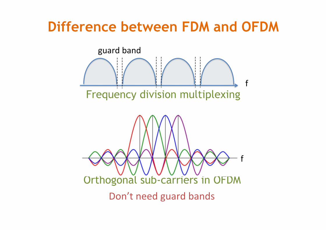
Difference between FDM and OFDM
f
guard band
Frequency division multiplexing
Orthogonal sub-carriers in OFDM Don’t need guard bands
f

Orthogonal Frequency Division Modulation
Data coded in frequency domain
f IFFT
* x[1]
* x[2]
* x[3]
… t
TransformaNon to Nme domain: each frequency is a sine wave In Nme, all added up
receive
Time domain signal Frequency domain signal
FFT
Decode each subcarrier separately
transmit

OFDM Transmitter and Receiver

Orthogonality of Sub-carriers
x(t) = X[k]e j2πkt Nk=−N 2
N 2−1
∑
Encode: frequency-domain samples à time-domain sample IFFT
Time-domain Frequency-domain
Decode: time-domain samples à frequency-domain sample FFT
X[k]= 1N
x(t)e− j2πkt Nt=N 2
N 2−1
∑
Orthogonality of any two bins : e− j2πkt Ne− j2π pt Nt=−N 2
N 2−1
∑ = 0,∀p ≠ k

Example § Say we use BPSK and 4 sub-carriers to transmit a
stream of samples
§ Serial to parallel conversion of samples
§ Parallel to serial conversion, and transmit time-domain samples
c1 c2 c3 c4 symbol1 1 1 -‐1 -‐1 symbol2 1 1 1 -‐1 symbol3 1 -‐1 -‐1 -‐1 symbol4 -‐1 1 -‐1 -‐1 symbol5 -‐1 1 1 -‐1 symbol6 -‐1 -‐1 1 1
Frequency-‐domain signal Time-‐domain signal
0 2 -‐ 2i 0 2 + 2i 2 0 -‐ 2i 2 0 + 2i -‐2 2 2 2 -‐2 0 -‐ 2i -‐2 0 + 2i 0 -‐2 -‐ 2i 0 -‐2 + 2i 0 -‐2 + 2i 0 -‐2 -‐ 2i
IFFT
0, 2 -‐ 2i, 0, 2 + 2i, 2, 0 -‐ 2i, 2, 0 + 2i, -‐2, 2, 2, 2, -‐2, 0 -‐ 2i, -‐2, 0 + 2i, 0, -‐2 -‐ 2i, 0, -‐2 + 2i, 0, -‐2 + 2i, 0, -‐2 -‐ 2i, …
1, 1, -‐1, -‐1, 1, 1, 1, -‐1, 1, -‐1, -‐1, -‐1, -‐1, 1, -‐1, -‐1, -‐1, 1, 1, -‐1, -‐1, -‐1, 1, 1

t2
symbol1 1 1 -‐1 -‐1 symbol2 1 1 1 -‐1 symbol3 1 -‐1 -‐1 -‐1 symbol4 -‐1 1 -‐1 -‐1 symbol5 -‐1 1 1 -‐1 symbol6 -‐1 -‐1 1 1
bin1
bin2
bin3
bin4
t1 t3 t4 t5 t6

Multi-Path Effect
y(t) = h(0)x(t)+ h(1)x(t −1)+ h(2)x(t − 2)+
= h(Δ
∑ Δ)x(t −Δ) = h(t)⊗ x(t)
time-domain
⟺ Y ( f ) = H ( f )X( f )
frequency-domain

Current symbol + delayed-version symbol à Signals are deconstructive in only certain frequencies

Frequency Selective Fading
Frequency selecNve fading: Only some sub-‐carriers get affected Can be recovered by proper coding!
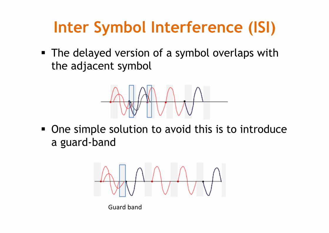
§ The delayed version of a symbol overlaps with the adjacent symbol
§ One simple solution to avoid this is to introduce a guard-band
Inter Symbol Interference (ISI)
Guard band

§ However, we don’t know the delay spread exactly – The hardware doesn’t allow blank space because it needs
to send out signals continuously
§ Solution: Cyclic Prefix – Make the symbol period longer by copying the tail and
glue it in the front
Cyclic Prefix (CP)
In 802.11, CP:data = 1:4

§ Because of the usage of FFT, the signal is periodic
§ Del the time domain corresponds to rotation ay in in the frequency domain – Can still obtain the correct signal in the frequency
domain by compensating this rotation
Cyclic Prefix (CP)
FFT( ) = exp(-‐2jπΔf)*FFT( ) delayed version original signal

Cyclic Prefix (CP)
original signal
y(t) à FFT( ) àY[k] = H[k]X[k] w/o mulNpath
w mulNpath
original signal + delayed-‐version signal
y(t) à FFT( ) àY[k] = α(1+exp(-‐2jπΔk))*X[k] = H’[k]X[k]
Lump the phase shie in H

Side Benefit of CP § Allow the signal to be decoded even if the
packet is detected after some delay
decodable undecodable

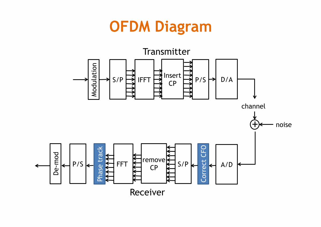
OFDM Diagram
Mod
ulat
ion
S/P IFFT P/S Insert
CP D/A
channel
noise +
A/D
De-
mod
P/S FFT S/P remove
CP
Transmitter
Receiver

Unoccupied Subcarriers
• Edge sub-carriers are more vulnerable to errors under discrete FFT � Frequency might be shifted due to noise or multi-path
• Leave them unused � In 802.11, only 48 of 64 bins are occupied bins
• Is it really worth to use OFDM when it costs so many overheads (CP, unoccupied bins)?

Synchronization
§ DAC (at Tx) and ADC (at Rx) never have exactly the same sampling period – A slow shift of the symbol timing point, which
rotates subcarriers – Intercarrier interference (ICI), which causes loss of
the orthogonality of the subcarriers
DAC (Tx)
ADC (Rx)

Carrier Frequency Offset (CFO)
§ The oscillators of Tx and Rx are not typically tuned to identical frequencies – Up-convert baseband signal sn to passband signal
yn=sn*ej2πftxnTs
– Down-convert passband signal yn back to rn=sn*ej2πftxnTs*e-j2πfrxnTs=sn*ej2πfΔnTs
DAC (Tx)
ADC (Rx)
ftx
frx Error accumulate!

Correct CFO in Time Domain
Symbol 1 Symbol 2
sn Sn+N
rn=sn*ej2πfΔnTs rn+N=sn+N*ej2πfΔ(n+N)Ts
rnrn+N* = sne
j2π fΔnTs sn+N* e− j2π fΔ (n+N )Ts
= e− j2π fΔNTs snsn+N*
= e− j2π fΔNTs sn2
z = rnrn+N*
n=1
L
∑
= e− j2π fΔNTs snsn+N*
n=1
L
∑
= e− j2π fΔNTs sn2
n=1
L
∑
fΔ =1
2πNTs∠z

Sampling Frequency Offset (SFO)
§ The transmitter and receiver may sample the signal at slightly different offset – Rotate the signal
§ All subcarriers experience the same sampling delay, but have different frequencies
DAC (Tx)
ADC (Rx)
tΔ
Yi=HiXi * ej2πtΔiNs/Nj
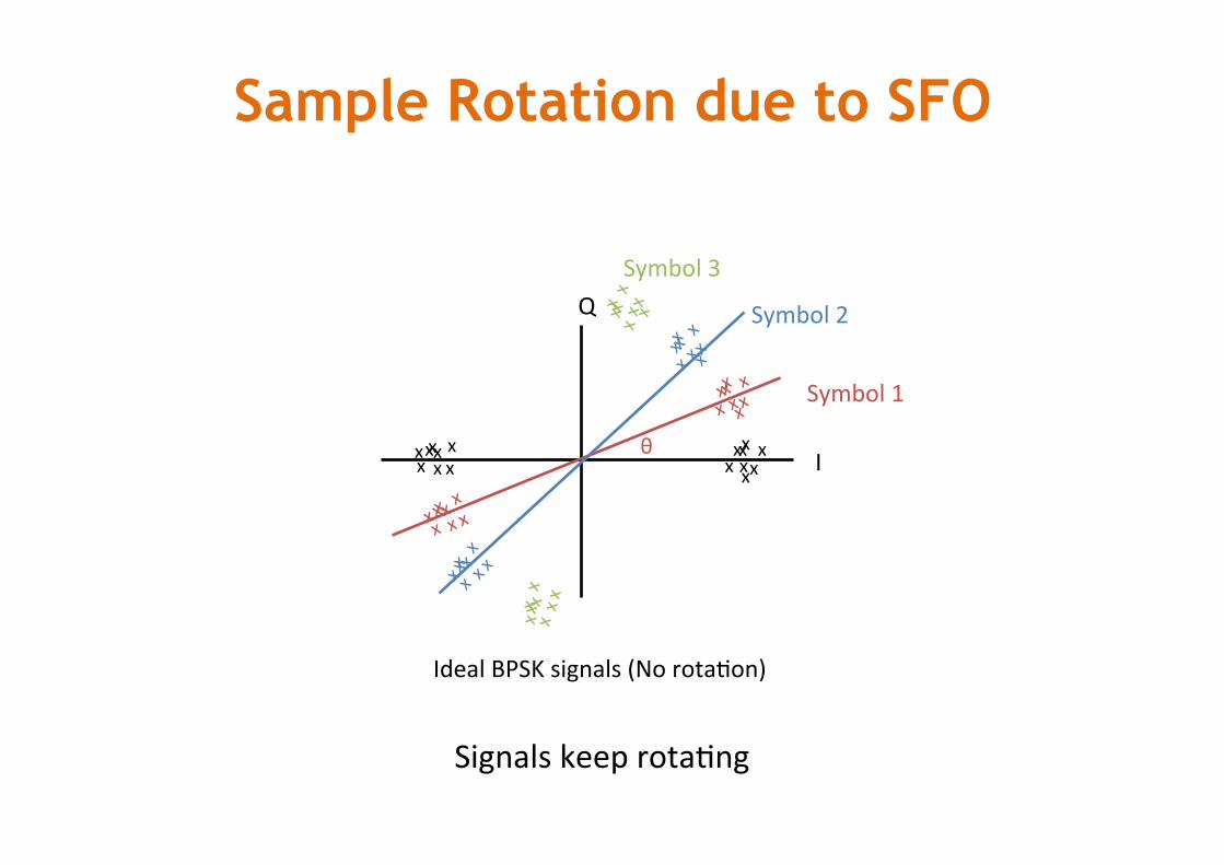
Sample Rotation due to SFO
I
Q
x x x x
x x x
x x x x x x x x
x
Ideal BPSK signals (No rotaNon)
θ
x x
x x
x x x x
x x
x x
x x
x x
Symbol 1
Symbol 2
Symbol 3
Signals keep rotaNng
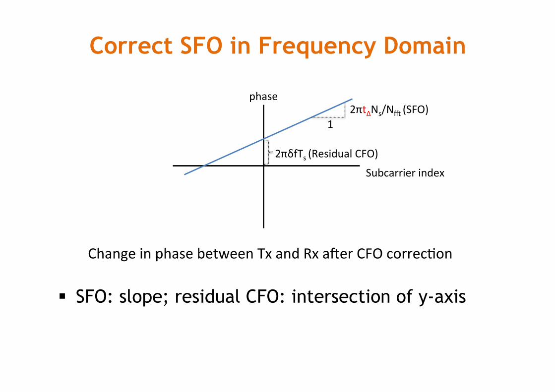
Correct SFO in Frequency Domain
§ SFO: slope; residual CFO: intersection of y-axis
2πδfTs (Residual CFO)
1 2πtΔNs/Nj (SFO)
Change in phase between Tx and Rx aeer CFO correcNon
Subcarrier index
phase
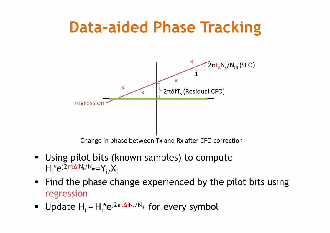
Data-aided Phase Tracking
§ Using pilot bits (known samples) to compute Hi*ej2πtΔiNs/Nfft=Yi/Xi
§ Find the phase change experienced by the pilot bits using regression
§ Update Hi = Hi*ej2πtΔiNs/Nfft for every symbol
2πδfTs (Residual CFO)
1 2πtΔNs/Nj (SFO)
Change in phase between Tx and Rx aeer CFO correcNon
x x
x
x
regression

After Phase Tracking
I
Q
x x x x
x x x
x x x x x x x x
x
Symbol 1
Aeer correcNon
θ
Symbol 2

Nondata-aided Phase Tracking
I
Q
x x x x
x x x
x x x x x x x x
x
Symbol 1
θ
OFDM Diagram
Mod
ulat
ion
S/P IFFT P/S Insert
CP D/A
channel
noise +
A/D
De-
mod
P/S FFT S/P remove
CP
Transmitter
Receiver Co
rrec
t CF
O
Phas
e tr
ack