pdf operator and service manual om/sm-tdb/7(ce) · important information - keep for operator -...
TRANSCRIPT

IMPORTANT INFORMATION - KEEP FOR OPERATOR - IMPORTANT INFORMATION-
Pull Tilt ModelCrank Tilt Model
OPERATOR AND SERVICE MANUAL OM/SM-TDB/7(CE)Part Number 128433 INTERNATIONAL
MODEL: TDB/7 (CE)Steam Jacketed Kettle
Self-ContainedElectric heatedTable top mountedStainless SteelTilting
THIS MANUAL MUST BE RETAINED FOR FUTURE REFERENCE. READ, UNDERSTANDAND FOLLOW THE INSTRUCTIONS AND WARNINGS CONTAINED IN THIS MANUAL.
FOR YOUR SAFETYDO NOT STORE OR USE GASOLINE OR OTHER FLAMMABLE VAPORS AND LIQUIDSIN THE VICINITY OF THIS OR ANY OTHER APPLIANCE.
Information contained in this document is known to be current and accurate at the time of printing/creation. Unified Brands recom-mends referencing our product line websites, unifiedbrands.net, for the most updated product information and specifications.

OM/SM-TDB/7(CE)
2
IMPORTANT — READ FIRST — IMPORTANTTHESE APPLIANCES MUST BE INSTALLED BY A COMPETENT PERSON IN CONFORMITY WITH THEINSTALLATION AND SERVICING INSTRUCTIONS AND NATIONAL REGULATIONS IN FORCE AT THE TIME.PARTICULAR ATTENTION MUST BE PAID TO THE FOLLOWING:
I. E. E. REGULATIONS FOR ELECTRICAL INSTALLATIONS
ELECTRICITY AT WORK REGULATIONS
HEALTH AND SAFETY AT WORK ACT
FIRE PRECAUTIONS ACT
LOCAL AND NATIONAL BUILDING REGULATIONS
USERS SHOULD BE CONVERSANT WITH APPROPRIATE PROVISIONS OF THE FIRE PRECAUTIONS ACT.IN PARTICULAR THEY SHOULD BE AWARE OF THE NEED FOR REGULAR SERVICING BY A COMPETENTPERSON TO ENSURE CONTINUED SAFE AND EFFICIENT APPLIANCE PERFORMANCE.
WARNING: TO PREVENT SHOCKS, APPLIANCES WHETHER GAS OR ELECTRIC, MUST BE EARTHED.
UPON COMPLETION OF INSTALLATION, THE OWNERS MANUAL SHOULD BE HANDED TO USERS ANDTHE INSTALLER SHOULD INSTRUCT RESPONSIBLE PERSON(S) IN THE CORRECT OPERATION ANDMAINTENANCE OF THE APPLIANCE.
THIS EQUIPMENT IS ONLY FOR PROFESSIONAL USE, AND SHALL BE OPERATED BY QUALIFIEDPERSONS. IT IS THE RESPONSIBILITY OF THE SUPERVISOR OR EQUIVALENT TO ENSURE THAT USERSWEAR PROTECTIVE CLOTHING, AND TO DRAW ATTENTION TO THE FACT THAT, SOME PARTS WILL,BY NECESSITY, BECOME VERY HOT AND WILL CAUSE BURNS IF TOUCHED ACCIDENTALLY.
UNLESS OTHERWISE STATED, PARTS WHICH HAVE BEEN PROTECTED BY THE MANUFACTURER ARENOT TO BE ADJUSTED BY THE INSTALLER.
BEFORE ATTEMPTING ANY SERVICING, ENSURE THAT THE ELECTRICAL SUPPLY IS DISCONNECTED.
WARNING: THE UNIT MUST BE INSTALLED BY PERSONNEL QUALIFIED TO WORK WITHELECTRICITY. IMPROPER INSTALLATION CAN RESULT IN INJURY TO PERSONNELAND/OR DAMAGE TO EQUIPMENT. THE UNIT MUST BE INSTALLED IN ACCORDANCEWITH APPLICABLE CODES.
CAUTION: SHIPPING STRAPS ARE UNDER TENSION AND CAN SNAP BACK WHEN CUT.
WARNING: TO AVOID DAMAGE OR INJURY, FOLLOW THE WIRING DIAGRAM EXACTLY WHENCONNECTING A UNIT.
WARNING: BEFORE CLEANING THE OUTSIDE OF THE KETTLE, DISCONNECT ELECTRIC POWER .KEEP WATER AND SOLUTIONS OUT OF CONTROLS AND ELECTRICAL COMPONENTS.
NOTICE: DO NOT USE ANY DE-GREASER THAT CONTAINS POTASSIUM HYDROXIDE OR SODIUMHYDROXIDE OR THAT IS ALKALINE.
WARNING: USE OF ANY REPLACEMENT PARTS OTHER THAN THOSE SUPPLIED BY GROEN ORTHEIR AUTHORIZED DISTRIBUTOR VOIDS ALL WARRANTIES AND CAN RESULT INBODILY INJURY TO THE OPERATOR AND DAMAGE THE EQUIPMENT. SERVICE BYOTHER THAN FACTORY-AUTHORIZED PERSONNEL WILL VOID ALL WARRANTIES.
WARNING: HIGH VOLTAGE EXISTS INSIDE CONTROL COMPARTMENTS. DISCONNECT FROMBRANCH BEFORE SERVICING. FAILURE TO DO SO CAN RESULT IN SERIOUS INJURY ORDEATH.
CAUTION: BE SURE ALL OPERATORS READ, UNDERSTAND AND FOLLOW THE OPERATINGINSTRUCTIONS, CAUTIONS, AND SAFETY INSTRUCTIONS CONTAINED IN THIS MANUAL.
WARNING: THIS UNIT IS INTENDED FOR USE IN THE COMMERCIAL HEATING, COOKING ANDHOLDING OF WATER AND FOOD PRODUCTS, PER THE INSTRUCTIONS CONTAINED INTHIS MANUAL. ANY OTHER USE COULD RESULT IN SERIOUS PERSONAL INJURY ORDAMAGE TO THE EQUIPMENT AND WILL VOID WARRANTY.

OM/SM-TDB/7(CE)
3
WARNING: AVOID ALL DIRECT CONTACT WITH HOT EQUIPMENT SURFACES. DIRECT SKINCONTACT COULD RESULT IN SEVERE BURNS.
WARNING: AVOID ALL DIRECT CONTACT WITH HOT FOOD OR WATER IN THE KETTLE. DIRECTCONTACT COULD RESULT IN SEVERE BURNS.
CAUTION: DO NOT OVER FILL THE KETTLE WHEN COOKING, HOLDING OR CLEANING. KEEPLIQUIDS A MINIMUM OF 2-3” (5-8 cm) BELOW THE KETTLE BODY RIM TO ALLOWCLEARANCE FOR STIRRING, BOILING AND SAFE PRODUCT TRANSFER.
WARNING: TAKE SPECIAL CARE TO AVOID CONTACT WITH HOT KETTLE BODY OR HOT PRODUCTWHEN ADDING INGREDIENTS, STIRRING OR TRANSFERRING PRODUCT TO ANOTHERCONTAINER.
WARNING: WHEN TILTING KETTLE FOR PRODUCT TRANSFER:1) WEAR PROTECTIVE OVEN MITT AND PROTECTIVE APRON.2) USE CONTAINER DEEP ENOUGH TO CONTAIN AND MINIMIZE PRODUCT SPLASHING.3) PLACE CONTAINER ON STABLE, FLAT SURFACE, AS CLOSE TO KETTLE AS
POSSIBLE.4) STAND TO LEFT OR RIGHT SIDE OF KETTLE WHILE POURING. DO NOT STAND
DIRECTLY IN POUR PATH OF HOT CONTENTS.5) POUR SLOWLY, MAINTAIN CONTROL OF KETTLE, AND RETURN KETTLE BODY TO
UPRIGHT POSITION AFTER CONTAINER IS FILLED OR TRANSFER IS COMPLETE.6) DO NOT OVER-FILL CONTAINER. AVOID DIRECT SKIN CONTACT WITH HOT
CONTAINER AND ITS CONTENTS.
CAUTION: KEEP FLOORS IN FRONT OF KETTLE WORK AREA CLEAN AND DRY. IF SPILLS OCCUR,CLEAN IMMEDIATELY, TO AVOID SLIPS OR FALLS.
WARNING: FAILURE TO CHECK SAFETY VALVE OPERATION PERIODICALLY COULD RESULT INPERSONAL INJURY AND/OR DAMAGE TO EQUIPMENT.
WARNING: WHEN TESTING, AVOID ANY EXPOSURE TO THE STEAM BLOWING OUT OF THE SAFETYVALVE. DIRECT CONTACT COULD RESULT IN SEVERE BURNS.
WARNING: BEFORE REPLACING ANY PARTS, DISCONNECT THE UNIT FROM THE ELECTRIC POWERSUPPLY.
WARNING: KEEP WATER AND SOLUTIONS OUT OF CONTROLS AND ELECTRICAL EQUIPMENT.NEVER SPRAY OR HOSE THE SUPPORT HOUSING OR ELECTRICAL CONNECTIONS.

OM/SM-TDB/7(CE)
4
Table of ContentsIMPORTANT OPERATOR WARNINGS . . . . . . . . . . . . . . . . . . . . . . . . . . . . . . . . . . . . . . . . . . . . . . . . . . . . . . . . . 2
EQUIPMENT DESCRIPTION . . . . . . . . . . . . . . . . . . . . . . . . . . . . . . . . . . . . . . . . . . . . . . . . . . . . . . . . . . . . . . . . . 5
INSPECTION & UNPACKING . . . . . . . . . . . . . . . . . . . . . . . . . . . . . . . . . . . . . . . . . . . . . . . . . . . . . . . . . . . . . . . . . 7
INSTALLATION . . . . . . . . . . . . . . . . . . . . . . . . . . . . . . . . . . . . . . . . . . . . . . . . . . . . . . . . . . . . . . . . . . . . . . . . . . . . 8
INITIAL START-UP . . . . . . . . . . . . . . . . . . . . . . . . . . . . . . . . . . . . . . . . . . . . . . . . . . . . . . . . . . . . . . . . . . . . . . . . . 9
OPERATION . . . . . . . . . . . . . . . . . . . . . . . . . . . . . . . . . . . . . . . . . . . . . . . . . . . . . . . . . . . . . . . . . . . . . . . . . . . . . 10
SEQUENCE OF OPERATION . . . . . . . . . . . . . . . . . . . . . . . . . . . . . . . . . . . . . . . . . . . . . . . . . . . . . . . . . . . . . . . . 12
MAINTENANCE . . . . . . . . . . . . . . . . . . . . . . . . . . . . . . . . . . . . . . . . . . . . . . . . . . . . . . . . . . . . . . . . . . . . . . . . . . 13
TROUBLESHOOTING . . . . . . . . . . . . . . . . . . . . . . . . . . . . . . . . . . . . . . . . . . . . . . . . . . . . . . . . . . . . . . . . . . . . . . 15
CLEANING . . . . . . . . . . . . . . . . . . . . . . . . . . . . . . . . . . . . . . . . . . . . . . . . . . . . . . . . . . . . . . . . . . . . . . . . . . . . . . . 19
PARTS LISTS . . . . . . . . . . . . . . . . . . . . . . . . . . . . . . . . . . . . . . . . . . . . . . . . . . . . . . . . . . . . . . . . . . . . . . . . . . . . 21
SCHEMATICS . . . . . . . . . . . . . . . . . . . . . . . . . . . . . . . . . . . . . . . . . . . . . . . . . . . . . . . . . . . . . . . . . . . . . . . . . . . . 25
SERVICE LOG . . . . . . . . . . . . . . . . . . . . . . . . . . . . . . . . . . . . . . . . . . . . . . . . . . . . . . . . . . . . . . . . . . . . . . . . . . . . 26
REFERENCES . . . . . . . . . . . . . . . . . . . . . . . . . . . . . . . . . . . . . . . . . . . . . . . . . . . . . . . . . . . . . . . . . . . . . . . . . . . . 26
WARRANTY . . . . . . . . . . . . . . . . . . . . . . . . . . . . . . . . . . . . . . . . . . . . . . . . . . . . . . . . . . . . . . . . . . . . . . . . . . . . . . 27

OM/SM-TDB/7(CE)
5
Equipment Description
The Groen TDB/7 is a table top, tilting, steamjacketed kettle with a thermostatically controlled,self-contained, electrically-heated steam supply andappropriate controls, mounted on a sturdy base. TheModel TDB/7 is available in 20 or 40 - quart capacity.
The body of the TDB/7 Kettle is constructed ofstainless steel, welded into one solid piece. Thekettle is furnished with a reinforced rim and abutterfly shaped pouring lip. It has a steam jacketrated for pressures up to 50 PSIG. Kettle finish is180 emery grit on the inside and bright semi-deluxeon the outside. A tilt handle allows the operator tomanually tilt the kettle body in a controlled manner. Acrank tilt model is also available. Pouring heightaccepts pans up to 4 inches high on a table top.
A built-in steam generator, sized for the kettlecapacity and heated by electricity, delivers steaminto the jacket. “Airless” operation of the steamjacket permits uniform, efficient heating attemperatures as low as 150°F and as high as 295°F.In addition to the adjustable thermostat for operatingcontrol, the unit has a tilt cut-off switch, low watercut-off, safety valve, and high-limit pressure switchas safety features. A heating indicator light,pressure gauge, and sight glass are provided formonitoring kettle operation.
A single electrical connection is required forinstallation. The unit may be ordered for use with 230Volt single phase or 400 Volt three phase power.
KETTLE CHARACTERISTICSTDB/7-20+ TDB/7-40
Kettle Capacity 20 qts. 18.8 liters 40 qts. 37.6 liters
Jacket Capacity 4 qts. 3.7 liters 5 qts. 4.7 liters
Diameter 14” 36 cm 16-1/2” 42 cm
Depth 11” 28 cm 14-1/4” 36 cm
Base Width 24” 60 cm 24” 60 cm
Base Depth 16” 41 cm 16” 41 cm
KW at 230 Volt Single Phase 7.8 13.3
KW at 400 Volt Three Phase 7.8 13.3
Rated Amp Load - 1M 33 57
Rated Amp Load - 3M 11 (L1, L2, L3) 19 (L1, L2, L3)

OM/SM-TDB/7(CE)
6
Pull Tilt TDB/7, CE Model
Crank Tilt TDB/7, CE Model
Models
Optional equipment available with any model:1. Stand that supports the unit and holds a pan in position for filling2. Lift-off cover3. Basket insert4. Fill faucet5. Manual stirrers (factory installed)6. Motor driven agitator (factory installed)

OM/SM-TDB/7(CE)
7
The TDB/7 is shipped from the factory strapped on apallet. If the unit is a pull tilt model, the handle is packedinside the kettle for shipment.
Inspection & UnpackingThe unit will arrive in a heavy shipping carton and willbe attached to a skid. Immediately upon receipt,inspect the carton carefully for exterior damage.
CAUTIONSHIPPING STRAPS ARE UNDER TENSIONAND CAN SNAP BACK WHEN CUT. TAKECARE TO AVOID PERSONAL INJURY ORDAMAGE TO THE UNIT BY STAPLES LEFTIN THE WALLS OF THE CARTON.
Carefully cut the polyester straps around the cartonand detach the sides of the box from the skid. Pullthe carton up off the unit.
Thoroughly inspect the unit for concealed damage.Report any shipping damage or incorrect shipmentsto the delivery agent.
Write down the model number, serial number, andinstallation date, and retain this information
for future reference. Space for these entries isprovided at the top of the Service Log at the back of this manual. Keep this manual on file and availablefor operators to use.
CAUTIONTHIS UNIT WEIGHS 140 TO 163 LB. (64 TO74 KG). INSTALLER SHOULD OBTAINHELP AS NEEDED TO LIFT THIS WEIGHTSAFELY.
When installation is to begin, carefully cut the strapswhich hold the unit on the skid. Lift the unit straightup off the skid. Examine packing materials to besure loose parts are not discarded with the materials.
Attach the tilt handle (normally shipped inside thekettle) by carefully threading it into the socket on thetrunnion support. Be careful to avoid cross-threadingfine socket threads. This step is unnecessary if thekettle is a crank tilt model.

OM/SM-TDB/7(CE)
8
Installation
The Groen Kettle is provided withcomplete internal wiring. It is ready forimmediate connection. A wiring diagramis provided in this manual and on theinside of the control housing servicepanel. Any mechanical or electrical changes must beapproved by Groen’s Food Service EngineeringDepartment.
WARNINGINSTALLATION OF THE KETTLE MUST BEDONE BY PERSONNEL QUALIFIED TOWORK WITH ELECTRICITY. IMPROPERINSTALLATION CAN RESULT IN INJURYTO PERSONNEL AND/OR DAMAGE TOEQUIPMENT.
The completed unit has been operated at the factoryto test all controls and heater elements.
1. Set the kettle in place and level it. The baseshould be securely fastened to a table or worksurface. Four 3/8”-16 N.C. threaded couplingsare provided in the base of unit. Installationunder a ventilation hood is recommended.
2. Provide electrical power as specified on theelectrical information plate attached to theequipment. Observe all local and nationalcodes, and all regulations in force at the timeof installation.
3. The equipment is shipped ready for threephase operation. Refer to the wiring diagramfor single phase operation.
4. Bring the electrical service through theentrance at the rear of the support housing,making a watertight connection with theincoming lines. (A BX connection is notrecommended.) Observe all local andnational codes, and all regulations in force atthe time of installation.
DANGERELECTRICALLY GROUND THE UNIT ATTHE TERMINAL PROVIDED. FAILURE TOGROUND UNIT COULD RESULT INELECTROCUTION AND DEATH.
5. Confirm that the jacket water level is abovemid point of sight glass. If the level is low,follow the instructions under “Jacket Fillingand Water Treatment,” Page 14.
6. Electrically earth the unit at the terminalprovided.
7. Equipotential terminal: In accordance withnational regulations, the unit has been fittedwith an equipotential terminal.
TDB/7 ELECTRICAL SPECIFICATIONS
20 QUARTS 40 QUARTS
VOLTAGE PHASE KW AMPS KW AMPS
230 1 7.8 33 13.3` 57
400 3 7.8 11.2 13.3 19
ELECTRICAL SUPPLY CONNECTIONREQUIREMENTS
Unit TDB/7-20 TDB/7-40
230V - 1 Phase 33 Amps 57 Amps400V - 3 Phase 33 Amps 57 Amps

OM/SM-TDB/7(CE)
9
A simple turn of the thermostat controls the GroenTBD/7 Kettle
Initial Start-Up
IMPORTANT:BE SURE ALL OPERATORS READ, UNDERSTAND AND FOLLOW THE OPERATINGINSTRUCTIONS, CAUTIONS, AND SAFETY INSTRUCTIONS CONTAINED IN THIS MANUAL.
Now that the kettle has been installed, you shouldtest it to ensure that the unit is operating correctly.
1. Remove all literature and packing materialsfrom inside and outside of the unit.
2. Confirm that the kettle tilts properly. Eitherturn the crank or use the handle to tilt thekettle and return it to the upright position.
2. Turn on the electrical service to the unit.
3. Pour two to four liters of water into the kettle.
4. Following “To Start Kettle” instructions in the“Operation” section of this manual, beginheating the water at the highest thermostatsetting. The heating indicator light shouldcome on immediately, and heating shouldcontinue until the water boils.
WARNING AVOID ALL DIRECT CONTACT WITH HOTSURFACES. DIRECT SKIN CONTACTCOULD RESULT IN SEVERE BURNS.
AVOID ALL DIRECT CONTACT WITH HOTFOOD OR WATER IN THE KETTLE.DIRECT CONTACT COULD RESULT INSEVERE BURNS.
5. To shut down the unit, turn the thermostat dial to“OFF”.
If the unit functions as described above, it is readyfor use. If the unit does not function as intended,contact your local Groen Certified Service Agency.
OM/SM-TDB/7(CE)
10
On most TDB/7 units the jacket water level is shownin a sight glass, right on the kettle.
Operation
CE units have three lights on the Control Panel. The“POWER” light comes on when the the unit is turnedon. It indicates that power is being supplied to the unit. The “HEAT” light comes on when heating elements areheating the kettle. The “LOW WATER” light will comeon when the water level in the jacket falls belowacceptable operating levels. Refer to “Jacket Filling andWater Treatment” on Page 14.
A. To Start Kettle
1. EVERY DAY make sure that the jacket waterlevel is above the mid-point of the roundsight glass. If the level is low, service isnecessary.
2. Check the pressure gauge. If the gauge doesnot show 20 to 30 inches of vacuum (i.e., areading of 20 to 30 below 0), see “JacketVacuum” on page 14.
3. Turn on the electrical power to the unit.
4. Turn the thermostat dial to the desiredsetting. The heating indicator light indicatesthat the kettle is heating, and cycling of thelight on and off indicates that the kettle isbeing held at the set temperature. Once ineach cycle the contactors in the supporthousing will make a clicking sound. This isnormal.
B. To Transfer Product or Empty KettleThe kettle is designed and manufactured to betilted in a controlled manner. On those unitsequipped with a tilt handle, grasp the insulatedplastic ball firmly. Maintain a firm grip on handlewhen tilting, while keeping kettle body in a tiltedposition and when SLOWLY returning the kettlebody to an upright position. On those equippedwith crank tilt, turn the handle. The kettle willremain in the position to which tilted until crankedagain.
WARNINGAVOID ALL DIRECT CONTACT WITH HOT SURFACES. DIRECT SKIN CONTACT COULDRESULT IN SEVERE BURNS.
AVOID ALL DIRECT CONTACT WITH HOT FOODOR WATER IN THE KETTLE. DIRECT CONTACTCOULD RESULT IN SEVERE BURNS. TAKE SPECIAL CARE TO AVOID CONTACT WITHHOT KETTLE BODY OR HOT PRODUCT, WHENADDING INGREDIENTS, STIRRING ORTRANSFERRING PRODUCT TO ANOTHERCONTAINER.

OM/SM-TDB/7(CE)
11
Lift the rear edge of the cover first.
CAUTIONDO NOT OVERFILL THE KETTLE WHENCOOKING, HOLDING OR CLEANING. KEEPLIQUIDS AT LEAST 2-3” (5-8 cm) BELOW THEKETTLE BODY RIM TO ALLOW CLEARANCEFOR STIRRING, BOILING PRODUCT AND SAFETRANSFER.
WARNING WHEN TILTING KETTLE FOR PRODUCTTRANSFER:1) WEAR PROTECTIVE OVEN MITT AND
PROTECTIVE APRON.2) USE DEEP CONTAINER TO CONTAIN AND
MINIMIZE PRODUCT SPLASHING.3) PLACE CONTAINER ON STABLE, FLAT
SURFACE, AS CLOSE TO KETTLE ASPOSSIBLE.
4) STAND TO LEFT OR RIGHT OF KETTLE(DEPENDING ON HANDLE PLACEMENT) WHILEPOURING — NOT DIRECTLY IN POUR PATH OFHOT CONTENTS.
5) POUR SLOWLY, MAINTAIN CONTROL OFKETTLE BODY HANDLE AT ALL TIMES, ANDRETURN KETTLE BODY TO UPRIGHTPOSITION AFTER CONTAINER IS FILLED ORTRANSFER IS COMPLETE.
6) DO NOT OVERFILL CONTAINER. AVOIDDIRECT SKIN CONTACT WITH HOTCONTAINER AND ITS CONTENTS.
CAUTIONKEEP FLOORS IN FRONT OF THE KETTLEWORK AREA CLEAN AND DRY. IF SPILLSOCCUR, CLEAN AT ONCE TO AVOID SLIPS ORFALLS.
Common Accessories
1. Lift Off Cover
As with stock pot cooking, an optional lift off covercan speed up the heating of water and foodproducts. A cover helps retain heat in the cookingvessel and reduces the amount of heat and humidityreleased into the kitchen. Use of a cover can reducesome product cook times and help maintain thetemperature, color and texture of products beingheld or simmered for extended periods.
Make sure the handle is secure on the lift off coverbefore using. ALWAYS use the handle to place orremove cover from the kettle. Wear protective ovenmitts and a protective apron.
When putting the cover on the kettle, position iton top of kettle rim, with its flat edge facing thepouring lip.
WARNINGAVOID ALL DIRECT CONTACT WITH HOT SURFACES. DIRECT SKIN CONTACT COULDRESULT IN SEVERE BURNS.
AVOID ALL DIRECT CONTACT WITH HOTFOOD OR WATER IN THE KETTLE. DIRECTCONTACT COULD RESULT IN SEVERE BURNS.
When removing cover:
a) Firmly grasp the handle.
b) Lift rear edge (farthest from operator) 1-2”(3-5 cm) to allow any steam and water vaporto escape the cooking vessel. Wait 2-3seconds.
c) Tilt cover to 45-60° angle and allow any hotcondensate or product to roll off cover backinto kettle.
d) Remove cover, ensuring that any remaininghot condensate or product does not drip onoperator, floor or work surfaces.
e) Place cover on safe, flat, sanitary, out-of-the-way surface, or return to kettle rim.

OM/SM-TDB/7(CE)
12
CAUTIONDO NOT TILT KETTLE BODY WITH COVER INPLACE. COVER MAY SLIDE OFF, CAUSINGINJURY TO OPERATOR.
2. Basket Insert
An optional kettle basket insert can assist in cookingwater-boiled products including eggs, potatoes,vegetables, shell fish, pasta and rice. The nylonmesh liner must be used when cooking productsmaller than the mesh size of the basket, which isapproximately 1/4” (6 mm). This includes rice andsmall pasta shapes.
Tips For Use.
a) Allow for the water displacement of the basketand product to be cooked. This may mean onlyfilling the kettle half full of water. Test the basketand product displacement with the kettle OFF,and with cold water in the kettle.
CAUTIONDO NOT OVERFILL THE KETTLE WHENCOOKING, HOLDING OR CLEANING. KEEPLIQUIDS A MINIMUM OF 2-3” (5-8 cm) BELOWTHE KETTLE BODY RIM TO ALLOW CLEARANCEFOR STIRRING, BOILING AND SAFE PRODUCTTRANSFER.
WARNINGAVOID ALL DIRECT CONTACT WITH HOTSURFACES. DIRECT SKIN CONTACT COULDRESULT IN SEVERE BURNS.
AVOID ALL DIRECT CONTACT WITH HOT FOODOR WATER IN THE KETTLE. DIRECT CONTACTCOULD RESULT IN SEVERE BURNS.
b) Load basket on a level, stable work surface.
c) Lift the loaded basket with both hands. Get helpfrom another person if the basket is too heavyfor safe handling.
d) Slowly lower product into kettle.
e) When removing basket with cooked product, liftbasket straight up, ensuring bottom of basketclears the rim and pouring lip of the kettle. Wearprotective oven mitts and protective apron.
f) Allow hot water to fully drain from product,
before moving basket away from the kettle.Do not rest kettle basket on kettle rim orpouring lip. If basket is too heavy forindividual to lift and safely move, get helpfrom another person. Remove productimmediately from basket into anothercontainer, being sure to avoid contact withhot product and hot basket or. . .
g) Place basket with food on stable, flatsurface, setting it inside a solid steamer orbake pan, to catch any remaining hot waterdraining from product.
Sequence of Operation
The following “action-reaction” outline is provided tohelp the user understand how the equipment works.
When the operator starts up the kettle by turning theoperating thermostat dial from “OFF” to a desiredsetting, the thermostat switch closes. This lights upthe heating indicator light and causes the contactorsto close, allowing power to flow to heating elements.When the temperature of the steam jacket reachesthe value corresponding to the dial setting, thethermostat switch opens. This turns off the heatingindicator light and causes the contactors to open,stopping the power to the heaters. As soon as thethermostat senses that the kettle is cooling below theset point, the thermostat switch closes, the heatingindicator light comes on, the contactors close, andthe heaters come on again. On-off cycling continues,keeping the kettle at the set temperature This is whythe heating indicator light cycles on and off duringnormal operation. Every time the kettle is tilted, thetilt cut-off switch interrupts the power supply to theheaters, so that the heating elements will not operatewhile not submerged in the jacket water.
If steam pressure greater than 50 PSI is generatedin the jacket, the safety valve will open and relievethe excess pressure.
If the jacket water level gets too low and the heatingelements overheat, the high-limit control will open,shutting off power to the elements until the kettlecools.
Setting the operating thermostat dial to “OFF” shutsdown all control and heating circuits.

OM/SM-TDB/7(CE)
13
Test the safety valve at least twice each month.
The pressure gauge should show a vacuum of 20to 30 inches when the kettle is cold.
MaintenanceNOTICE: Contact Groen or an authorized Groen representative when repairs are required.
1. Periodic Maintenance
A Maintenance & Service Log is provided at theback of this manual. Each time maintenance isperformed on your Groen kettle, enter the date ofthe work, what was done, and who did it. Keep thismanual on file and available for operators to use.
Periodic inspection will minimize equipment downtime and increase the efficiency of operation. Thefollowing points should be checked:
[BY OPERATOR]
a. Check the pressure/vacuum gauge every day. The gauge should show a vacuum of 20 to 30inches, when the kettle is cold. If it does not,see “Jacket Vacuum” on page 14.
b. Also check the jacket water level each day. Itshould be above mid point of the round sightglass. If the level is low, see “Jacket Filling andWater Treatment” on page 14.
[BY SERVICE TECHNICIAN]
c. Test the safety valve at least twice each month.Test the valve with the kettle operating at 15 psi(105 kPa), by pulling up the test chain for atleast five seconds. Then release the chain andlet the valve snap shut. If the valve does notactivate, (there is no evidence of discharge, orthe valve leaks) stop using the kettleimmediately and contact a qualified Groen
service representative.
d. The inside of the support housing should bekept clean.
e. At least twice a year, grease the two trunnionbearings. The bearings are located withinthe kettle support housing. Remove theaccess panels from the support housing witha screwdriver to gain access to the greasefittings. Use a lithium-based, multi-purposegrease. When the access panels areremoved, the mounting bolts for the trunnionbearings and tilt switch can also be checkedfor tightness.
WARNINGWHEN TESTING, AVOID ANY EXPOSURE TOTHE STEAM BLOWING OUT OF THE SAFETYVALVE. DIRECT CONTACT COULD RESULT INSEVERE BURNS.DISCONNECT ELECTRICAL POWER FROMTHE KETTLE BEFORE ATTEMPTING TOGREASE THE TRUNNION BEARINGS.
f. On the crank-tilt models, the gear housing hasfittings for proper lubrication of moving parts. Because the gears do not run in oil, periodic
OM/SM-TDB/7(CE)
14
lubrication with grease is necessary. Frequency oflubrication will depend on operating conditions, butthe service should be performed at least once everysix months.
Add grease through the Zerk fittings on the gearhousing until you see grease flow out of thebearings around the trunnion shaft. Also placea liberal amount of grease on the gear to coverthe arc that is in contact with the worm gear. When finished, reassemble access panels tosupport housing.
Electrical wiring should be kept securelyconnected and in good condition.
2. Jacket Vacuum
When the kettle is cold, a positive pressure readingor a reading around zero on the pressure/vacuumgauge indicates the presence of air in the jacket. Airin the jacket slows down the heating of the kettle.
To remove air:
a. Start the unit. (See the “Operation” section ofthis manual.) (Be sure there is water or productin the kettle when heating).
b. When the pressure/vacuum gauge reaches apositive pressure reading of five PSI, releasethe trapped air and steam by pulling up on thesafety valve for about 1 second. Repeat thisstep, then let the chain snap back into theclosed position.
3. Jacket Filling and Water Treatment
The jacket was charged at the factory with theproper amount of treated distilled water. You mayneed to restore the water to its proper level, eitherbecause water was lost as steam during venting orbecause treated water was lost by draining.
IMPORTANTPressure gauge must read 0 PSI or less beforeyou fill jacket with water.
To fill jacket with water:
a. If you are replacing water lost as steam, usedistilled water. If you are replacing treated waterthat ran out of the jacket, prepare more treatedwater as directed in step 3, “Water TreatmentProcedure”.
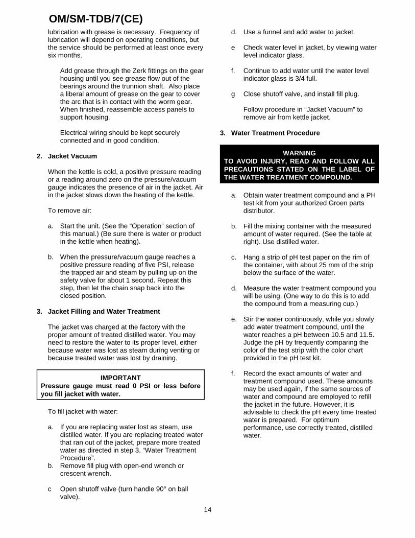
b. Remove fill plug with open-end wrench orcrescent wrench.
c Open shutoff valve (turn handle 90° on ballvalve).
d. Use a funnel and add water to jacket.
e Check water level in jacket, by viewing waterlevel indicator glass.
f. Continue to add water until the water levelindicator glass is 3/4 full.
g Close shutoff valve, and install fill plug.
Follow procedure in “Jacket Vacuum” toremove air from kettle jacket.
3. Water Treatment Procedure
WARNINGTO AVOID INJURY, READ AND FOLLOW ALLPRECAUTIONS STATED ON THE LABEL OFTHE WATER TREATMENT COMPOUND.
a. Obtain water treatment compound and a PHtest kit from your authorized Groen partsdistributor.
b. Fill the mixing container with the measuredamount of water required. (See the table atright). Use distilled water.
c. Hang a strip of pH test paper on the rim ofthe container, with about 25 mm of the stripbelow the surface of the water.
d. Measure the water treatment compound youwill be using. (One way to do this is to addthe compound from a measuring cup.)
e. Stir the water continuously, while you slowlyadd water treatment compound, until thewater reaches a pH between 10.5 and 11.5. Judge the pH by frequently comparing thecolor of the test strip with the color chartprovided in the pH test kit.
f. Record the exact amounts of water andtreatment compound used. These amountsmay be used again, if the same sources ofwater and compound are employed to refillthe jacket in the future. However, it isadvisable to check the pH every time treatedwater is prepared. For optimumperformance, use correctly treated, distilledwater.

OM/SM-TDB/7(CE)
15
Model Jacket Capacity
TDB/7-20 3.8 Liters
TDB/7-40 4.7 Liters
4. Component Replacement
WARNINGBEFORE REPLACING ANY PARTS,DISCONNECT THE UNIT FROM THEELECTRIC POWER SUPPLY.
Wiring is marked as shown on the schematicdrawings. Be sure new components are wired inthe same manner as the old.
TroubleshootingYour kettle is designed to operate smoothly and efficiently if properly maintained. However, the following is a list ofchecks in the event of a problem. Wiring diagrams are furnished inside the service panel and at the back of thismanual. Items followed by X, should only be done by a qualified service representative. USE OF ANYREPLACEMENT PARTS OTHER THAN THOSE SUPPLIED BY GROEN OR ITS AUTHORIZED DISTRIBUTORSCAN INJURE TO THE OPERATOR AND DAMAGE THE EQUIPMENT AND WILL VOID ALL WARRANTIES.
SYMPTOM WHO WHAT TO CHECKX indicates items which must be performed by an authorized technician.
Kettle will not heat, and heatingindicator will not come on.
User a. Electric power supply to the unit.b. Water level in jacket.
Auth ServiceRep Only
c. Control circuit fuses. Replace a blown fuse only with a fuse ofthe same AMP rating. X
d. For loose or broken wires. Xe. Tilt cut-off switch. Xf. That pressure switch is open. Xg. Operation of variable thermostat. Xh. Low water cutoff. X
Kettle will not heat, but heatingindicator comes on.
Auth ServiceRep Only
a. Contactor. Xb. Heater elements with ohmmeter for ground short or open
element. If element is defective, call Groen. XKettle continues heating after itreaches the desired temperature
User a. Thermostat dial setting.Auth ServiceRep Only
b. Thermostat circuit for short. Xc. Thermostat operation. The thermostat should click when the
dial is rotated above and below the setting for the temperatureof the kettle. X
d. Contactor, to determine whether it is energized or stuck. Kettle stops heating before itreaches the desired temperature.
User a. Thermostat dial setting.Auth ServiceRep Only
b. Thermostat calibration. Xc. Thermostat operation. The thermostat should click when the
dial is rotated above and below the setting for the temperatureof the kettle. X
Kettle heats slowly User a. For air in the jacket. See “Jacket Vacuum” in the“Maintenance” section of this manual.
Auth ServiceRep Only
b. Heater elements with ohmmeter for ground short or openelement. If an element is defective, call Groen. X
c. Voltage of main power source. XSafety valve pops. User a. For air in the jacket. See “Jacket Vacuum” in the
“Maintenance” section of this manual.Auth ServiceRep Only
b. Pressure switch setting. Xc. Thermostat operation. Thermostat should click when the dial
is rotated above and below the setting for the temperature ofthe kettle. X
d. Safety valve. If the valve pops at pressures below 49 PSI,replace it. X
e. Contactor, to determine whether it is de-energized. X

OM/SM-TDB/7(CE)
16
User Instructions
Regulations and Safety Precautions
These Appliances have been CE marked on the basis of compliance with the EMC and Low Voltage Directive.
These appliances MUST BE installed by a competent person in conformity with the INSTALLATION ANDSERVICING INSTRUCTIONS and National Regulations in force at the time.
Particular attention MUST be paid to the following:
I.E.E. Regulations for Electrical InstallationsElectricity at Work RegulationsHealth and Safety at Work ActFire Precautions ActLocal and National Building Regulations
Those parts which have been protected by the manufacturer MUST NOT be adjusted by the User.
Users should be conversant with the appropriate provisions of the Fire Precautions Act. In particular the need forregular servicing by a competent person to ensure the continued safe and efficient performance of the Appliance.
WARNINGTO PREVENT SHOCKS, ALL APPLIANCES WHETHER GAS OR ELECTRIC, MUST BE EARTHED.
Upon completion of the installation, the Owners Manual should be handed to the users and the installer shouldinstruct the responsible person(s) on the correct operation and maintenance of the Appliance. This equipment isONLY FOR PROFESSIONAL USE, and shall be operated by QUALIFIED persons. It is the responsibility of theSupervisor or equivalent to ensure that users wear SUITABLE PROTECTIVE CLOTHING and to draw attention tothe fact that, some parts will, by necessity, become VERY HOT and will cause burns if touched accidentally.
IMPORTANT - READ FIRST - IMPORTANT The Groen Steam Jacketed Kettle you have just purchased has beenhandcrafted from the finest materials, meticulously inspected, and carefully tested to ensure that you receive thebest possible product. With reasonable care and periodic maintenance, it will provide years of faithful service. It isrecommended that you establish a timetable for periodic maintenance as outlined in this manual. Space is providedin the Service Log at the back of this manual.
Equipment Description
General
Groen models TDB/7 are stainless steel, steamjacketed, table mounted, tilting kettles with a self-contained, electric-heated steam source. The kettlebody is welded into one piece and furnished with areinforced bar rim and welded "butterfly" pouring lip.The interior of the kettle is polished to a 180 emery gritfinish, and the exterior is given a bright semi-deluxefinish. The unit is ASME shop inspected and registeredwith the National Board for working pressures up to 50PSI. Kettle support, tilting mechanism, and controls arecontained in an enclosed base. Tilting is provided by aself-locking, worm-and-gear device, or by a tilt handle.
Charged at the factory with treated, distilled water, thesteam source provides kettle temperature of 65/ C to150/ C. Controls for the unit include a thermostat,pressure gauge, gauge glass, safety valve, pressurelimit control, low water cut-off and an on/off switch.
Service connections are required for 230 Volt, singlephase, 50 Hz and 400 Volt, three phase, 50 Hzelectricity.
IMPORTANT: Prior to operation, clean out thekettle pan thoroughly using hot water anddetergent. Rinse out and dry thoroughly.

OM/SM-TDB/7(CE)
17
Operational and Maintenance Safety
WARNINGINSTALLATION OF THE UNIT MUST BE DONE BY PERSONNEL QUALIFIED TO WORK WITHELECTRICITY AND PLUMBING IN ACCORDANCE WITH ALL APPLICABLE CODES.
BEFORE REPLACING ANY PARTS, DISCONNECT THE UNIT FROM THE ELECTRIC POWER SUPPLY.
TO PREVENT SHOCKS, ALL APPLIANCES WHETHER GAS OR ELECTRIC, MUST BE EARTHED.
CAUTIONBE SURE ALL OPERATORS READ, UNDERSTAND, AND FOLLOW THE OPERATING INSTRUCTIONS,CAUTIONS AND SAFETY INSTRUCTIONS CONTAINED IN THIS MANUAL.
Operation
1. Initial Operational Readiness Check
After the TDB/7 Kettle has been installed accordingto service and installation instructions, perform initialstart-up as a test, to ensure that the unit is operatingcorrectly.
a. Remove all literature and packing material fromthe interior and exterior of the unit.
b. Make sure electricity supply is switched on.
c. Ensure that the kettle is filled with water.
d. Check the water level in the jacket. The levelshould be between the lines on the gauge glass.If the level is low, the jacket water level will berequired to be topped up. (This will require aservice call).
e. Check the pressure gauge. If the gauge does notshow sufficient vacuum (20 to 30 below zero)then the jacket will require venting. (This willrequire a service call).
f. Switch the On/Off switch to the "On" position.The "power on" neon will illuminate.
g. Turn the thermostat dial to the required setting.The "heat" neon will illuminate.
WARNINGAVOID CONTACT WITH THE FLUE. SURFACESARE VERY HOT AND WILL CAUSE BURNS. DONOT OBSTRUCT FLUE OPENING.
2. To Shut Down Kettle
a. Turn the thermostat dial to the "Off'' position.
b. Switch the On/Off switch to the "Off" position.
c. For a prolonged shut down, turn the electricitymain off.
Follow steps a and b.
3. Filling the Kettle
Prior to operation, thoroughly clean the kettle usinghot water and detergent.
Kettle capacities:
Model Maximum CapacityTDB/7-20 18.8 LitresTDB/7-40 37.6 Litres
To prevent surge boiling, no more than 80% ofthe maximum capacity should be used.
4. Users Thermostat
Provides automatic control of the Kettle Jackettemperature at settings up to 147/ C maximum.
5. Sequence of Operation
The following “action-reaction” outline is provided tohelp the user understand how the equipment works.
When the operator starts up the kettle by turning theoperating thermostat dial from “OFF” to a desiredsetting, the thermostat switch closes. This lights upthe heating indicator light and causes the contactorsto close, allowing power to flow to heating elements.
When the temperature of the steam jacket reaches

OM/SM-TDB/7(CE)
18
the value corresponding to the dial setting, thethermostat switch opens. This turns off the heatingindicator light and causes the contactors to open,stopping the power to the heaters.
As soon as the thermostat senses that the kettle iscooling below the set point, the thermostat switchcloses, the heating indicator light comes on, thecontactors close, and the heaters come on again. On-off cycling continues, keeping the kettle at the settemperature. This is why the heating indicator lightcycles on and off during normal operation. Every timethe kettle is tilted, the tilt cut-off switch interrupts thepower supply to the heaters, so that the heatingelements will not operate while not submerged in thejacket water.
If steam pressure greater than 50 PSIG is generatedin the jacket, the safety valve will open and relieve theexcess pressure.
If the jacket water level gets too low before theheating elements overheat, the high-limit control willopen and shut off power to the elements until thekettle cools.
Setting the operating thermostat dial to “OFF” shutsdown all control and heating circuits.
6. To Empty Kettle
TDB/7 Kettles with Crank Tilt
To tilt the body of the kettle forward, turn the handcrank on the front of the cabinet anti-clockwise. Thebody will stay in the position it holds when you stopturning the handle. To return the body to the uprightposition, turn the crank clockwise.
TDB/7 Kettle with Tilt Handle
The kettle is designed to be tilted in a controlledmanner. Grasp the insulated plastic ball firmly. Maintain a firm grip on the handle when tilting, whilekeeping the kettle body in a tilted position, and whenslowly returning the kettle body to an uprightposition.
WARNINGDO NOT STAND IN FRONT OF THE KETTLEBODY WHEN TILTING IT. BE CAREFUL TOKEEP HOT CONTENTS FROM SPILLING.ENSURE PEOPLE ARE KEPT AWAY FROMTHE KETTLE WHEN EMPTYING THE KETTLE.
7. Power Failure
If the power to the unit fails do not attempt tooperate the appliance until the electricity supply isre-established.
When the power comes back on follow the steps inParagraph 8.2.1 Initial Kettle Operational ReadinessCheck.

OM/SM-TDB/7(CE)
19
Use only a sponge, cloth or plastic brush to cleanthe kettle.
Scrapers or steel wool can harm the kettle surface.
Cleaning
1. Suggested Tools:
a. Cleaner, such as Klenzade HC-10 or HC-32from ECOLAB, Inc.
b. Kettle brushes in good condition.
c. Sanitizer such as Klenzade XY-12.
d. Film remover such as Klenzade LC-30.
1. Precautions
Before cleaning, shut off the kettle by turning thethermostat dial to “OFF,” and shut off all electricpower to the unit at a remote switch, such as thecircuit breaker.
WARNING KEEP WATER AND SOLUTIONS AWAY FROMCONTROLS AND ELECTRICAL EQUIPMENT.NEVER SPRAY THE SUPPORT HOUSING ORELECTRICAL CONNECTIONS.
CAUTIONMOST CLEANERS ARE HARMFUL TO THESKIN, EYES, MUCOUS MEMBRANES, ANDCLOTHING. PRECAUTIONS SHOULD BETAKEN. WEAR RUBBER GLOVES, GOGGLESOR FACE SHIELD, AND PROTECTIVECLOTHING. READ THE WARNINGS ANDFOLLOW THE DIRECTIONS ON THE LABEL OFTHE CLEANER CAREFULLY
3. Procedure
a. Clean food-contact surfaces as soon aspossible after use. If the unit is in continuoususe, thoroughly clean and sanitize the interiorand exterior at least once every 12 hours.
WARNING AVOID ANY DIRECT CONTACT WITH HOTSURFACES. DIRECT SKIN CONTACT COULDRESULT IN SEVERE BURNS.
b. Scrape and flush out food residues. Be carefulnot to scratch the kettle with metalimplements.
c. Prepare a hot solution of the detergent/ cleaningcompound as instructed by the supplier. Cleanthe unit thoroughly. A cloth moistened withcleaning solution can be used to clean controls,housings, and electrical conduits.
d. Rinse the kettle thoroughly with hot water, thendrain completely.
e. As part of the daily cleaning program, cleansoiled external and internal surfaces.Remember to check the sides of the unit andcontrol housing.
f. To remove stuck materials, use a brush,sponge, cloth, plastic or rubber scraper, orplastic wool with the cleaning solution. Toreduce effort required in washing, let thedetergent solution sit in the kettle and soak intothe residue. Do NOT use abrasive materials or

OM/SM-TDB/7(CE)
20
metal tools that might scratch the surface.Scratches make the surface harder to cleanand provide places for bacteria to grow.
Do NOT use steel wool, which may leaveparticles in the surface and cause eventualcorrosion and pitting.
g. The outside of the unit may be polished with astainless steel cleaner such as “Zepper” fromZep Manufacturing Co.
h.h. When equipment needs to be sanitized, use asolution equivalent to one that supplies 200parts per million available chlorine. Obtainadvice on sanitizing agents from your supplierof sanitizing products. Following the supplier’sinstructions, apply the agent after the unit hasbeen cleaned and drained. Rinse off thesanitizer thoroughly.
NOTICENEVER LEAVE A CHLORINE SANITIZER INCONTACT WITH STAINLESS STEELSURFACES LONGER THAN 30 MINUTES.LONGER CONTACT CAN CAUSE STAININGAND CORROSION.
i. It is recommended that each piece of equipmentbe sanitized just before use.
j. If there is difficulty removing mineral deposits ora film left by hard water or food residues, cleanthe kettle thoroughly and then use a delimingagent, like Groen Delimer/Descaler (PartNumber 114800) or Lime-Away from Ecolab, inaccordance with the manufacturer’s directions.Rinse and drain the unit before further use.
k. If cleaning problems persist, contact yourcleaning product representative for assistance.The supplier has a trained technical staff withlaboratory facilities to serve you.

OM/SM-TDB/7(CE)
21
Parts List - Kettle Body - Pull Tilt Model
To order parts, contact your Groen Certified Service Agency. Supply the model designation, part description, partnumber, quantity, and, where applicable, voltage and phase.

OM/SM-TDB/7(CE)
22
Replacement Parts ListPull Tilt Models

OM/SM-TDB/7(CE)
23
Replacement Parts ListCrank Tilt Models

OM/SM-TDB/7(CE)
24
Parts List
To order parts, contact your Groen Certified Service Agency. Supply the model designation, part description, part number,quantity, and, where applicable, voltage and phase.
Key Description P/N H C Key Description P/N H C1 Base Weldment 122185 x x 36 Bullseye sight glass 108554 x x2 Cladding, top, pedestal 122052 x x 37 Thermostat knob 122054 x x3 Cladding, side, pedestal 122051 x x 38 Thermostat 012313 x x4 Cladding, panel, pedestal 122053 x x 39 Water level probe 015589 x x5 Pillow block, 1-1/2" bore 002989 x x 40 Bottom Cover 003141 x x6 Shim 122031 x x 41 Nut, hex 1/4-20 012940 x x7 Pedestal, machined 117786 x 42 Pressure switch 096963 x x8 Bearing with snap ring 002790 x 43 Reducing bushing 1/2 x 1/4 NPT 008739 x x9 Worm shaft 113057 x 44 Elbow Assembly 101543 x x10 Worm gear 3/4" bore 012026 x 45 Bottom cover bracket 002916 x x11 Spacer Washer 084956 x 46 Screw, round head #6-32 x 3/8" 009697 x x12 Hand wheel 012061 x 47 Thermostat adapter 107172 x x13 Roll pin, 1/4" x 1" 012614 x 48 Gasket bottom cover 007937 x x14 Gear bushing 113055 x 49 Safety Valve 097005 x x15 Set screw, socket 3/8-16 x 1" 005593 x 50 Pressure gauge 084208 x x16 Gear sector, 12 DP 009829 x 50a Pressure gauge lens 087635 x x17 Key, 1/4" sq x 1-1/4" round ends 009262 x 51 Water fill assembly 101528 x x18 Spacer washer 1/4" 122117 x 52 Kettle body wire harness 096938 x x19 Pedestal, weldment 128517 x 53 Handle assembly 012695 x20 Tilt switch & bracket assembly 127635 x 53a Ball knob 012691 x21 Stop assembly 065527 x 53b Tolerance ring 012692 x22 Set collar 065528 x 53c Handle rod 013597 x23 Grommet 003492 x x -- Equipotential terminal assembly 122021 x x24 Elec. component mounting panel 122103 x x -- Power light 116381 x x25 Contactor 122042 x x -- Heat & low water light 116382 x x26 Relay socket base 117738 x x -- Power switch 122004 x x27 Water level sensor 117737 x x -- Washer, lock 3/8", MS 005702 x x28 Terminal block 088214 x x -- Washer, lock 3/8" SS 005618 x x29 Fuse block 077840 x x -- Screw, hex 3/8-16 x 1" SS 005612 x x30 Ground lug 002863 x x -- Screw, hex 1/2-13 x 1" 005622 x x31 Tilt switch & bracket assembly 113074 x -- Washer, lock 1/2" 005735 x x32 Nut, Keps, 1/4-20 012940 x x -- Nut, hex 1/2-13 005705 x x35 Indicator lamp 016028 x x
H = Pull Tilt Model C = Crank Tilt Models– = Item not shown in illustrations

OM/SM-TDB/7(CE)
25
Wiring Diagram

OM/SM-TDB/7(CE)
26
Service Log
Model No. _______________________________ Purchased From _________________________
Serial No. _______________________________ Location ________________________________
Date Purchased __________________________ Date Installed ___________________________
Purchase Order No. ______________________ For Service Call __________________________
Date Service Performed Performed By
References
KLENZADE SALES CENTER ECOLAB. Inc.370 WabashaSt. Paul, Minnesota 55102800/352-5326 or 612/293-2233
NATIONAL FIRE PROTECTION ASSOCIATION60 Battery March ParkQuincy, Massachusetts 02269
NFPA/54 - Installation of Gas Appliances & GasPiping
NFPA/70 - The National Electrical Code
NATIONAL SANITATION FOUNDATION3475 Plymouth Rd.Ann Arbor, Michigan 48106
UNDERWRITERS LABORATORIES, INC.333 Pfingsten RoadNorthbrook, Illinois 60062
ZEP MANUFACTURING CO.1310-T Seaboard Industrial Blvd.Atlanta, Georgia 30318

OM/SM-TDB/7(CE)
27
Limited Warranty To Commercial Purchasers*(for Areas Outside of the U.S. and Canada)
Groen Foodservice Equipment ("Groen Equipment") has been skillfully manufactured, carefully inspectedand packaged to meet rigid standards of excellence. Groen warrants its Equipment to be free from defectsin material and workmanship for twelve months from date of installation or eighteen months from date ofshipment with the following conditions and subject to the following limitations.
I. This parts warranty is limited to Groen Equipment sold to the original commercial purchaser/users(but not original equipment manufacturers), at its original place of installation, in areas outside theU.S. and Canada.
II. Damage during shipment is to be reported to the carrier, is not covered under this warranty, and isthe sole responsibility of the purchaser/user.
III. Groen, or an authorized service representative, will repair or replace parts, at Groen's soleelection, for any Groen Equipment, including but not limited to, draw-off valves, safety valves, gasand electric components, found to be defective during the warranty period.
IV. This warranty does not cover boiler maintenance, calibration, or periodic adjustments as specifiedin operating instructions or manuals, and consumable parts such as scraper blades, gaskets,packing, etc., or labor costs incurred for removal of adjacent equipment or objects to gain accessto Groen Equipment. This warranty does not cover defects caused by improper installation, abuse,careless operation, or improper maintenance of equipment. This warranty does not cover damagecaused by poor water quality or improper boiler maintenance.
v. THIS WARRANTY IS EXCLUSIVE AND IS IN LIEU OF ALL OTHER WARRANTIES,EXPRESSED OR IMPLIED, INCLUDING ANY IMPLIED WARRANTY OF MERCHANTABILITYOR FITNESS FOR A PARTICULAR PURPOSE, EACH OF WHICH IS HEREBY EXPRESSLYDISCLAIMED. THE REMEDIES DESCRIBED ABOVE ARE EXCLUSIVE AND IN NO EVENTSHALL GROEN BE LIABLE FOR SPECIAL, CONSEQUENTIAL OR INCIDENTAL DAMAGESFOR THE BREACH OR DELAY IN PERFORMANCE OF THIS WARRANTY.
VI. Groen Equipment is for commercial use only. If sold as a component of another (O.E.M.)manufacturer's equipment or if used as a consumer product, such Equipment is sold AS IS andwithout any warranty.
* (Covers All Food Service Equipment Ordered After October 1,1995)
1055 Mendell Davis DriveJackson, MS 39272Telephone 601 373-3903Fax 601 373-9587
OM/SM-TDB/7(CE)Part Number 128433
Revised 7/99