pcs7 hs-training p01-p02 rc1102 en b
TRANSCRIPT

© Siemens AG 2011. All Rights Reserved.
Siemens Automation Cooperates with Education
(= SCE)

© Siemens AG 2011. All Rights Reserved
Siemens Automation Cooperates with Education
PCS7 HS -
Training Manuals Status: March 2011
PCS7 HS Training Manuals P01-P02_01_En_B.ppt

© Siemens AG 2011. All Rights Reserved.Industry SectorPage 3
P01-01 Process Description
P01-02 Hardware Configuration
P01-03 Plant Hierarchy
P01-04 Individual Drive Function
P01-05 Functional Safety
P01-06 Control Loop
P01-07 Sequential Function Chart
P02-01 HMI Generation
P02-02 Alarm Engineering
P02-03 Importing Plant Design Data
Instruction MODULE 1
Instruction MODULE 2
PCS7 Training Manuals Table of Contents

© Siemens AG 2011. All Rights Reserved.Industry SectorPage 4
Classification of process engineering plants
P&ID flow diagram of the lab installation
Locks and recipes for the lab installation
Objective
PCS7 Training Manuals Module 1 P01-01 Process Description

© Siemens AG 2011. All Rights Reserved.Industry SectorPage 5
Classification according to the number of fundamentally different products
Single product plant
Multi-product plant
Classification according to the physical structure of the plant
Single line plant
Multi-line plant
Multi-line/multi path plant
Lab installation as learning example
Multi-product and multi-line/multi-path plant
Hierarchical breakdown into 4 units
Classification of Process Engineering Plants
PCS7 Training Manuals Module 1 P01-01 Process Description

© Siemens AG 2011. All Rights Reserved.Industry SectorPage 6
P&ID Flow Diagram of the Lab Installation
PCS7 Training Manuals Module 1 P01-01 Process Description
Educt
tanksReactors
Rinsing
Product tanks
© Siemens AG 2011. All Rights Reserved.Industry SectorPage 7
Safe operation of the plant requires monitoring the process interventions
Requirements for the lab installation:
Actuators can be activated only if the main switch is on and Emergency Off is unlocked
Protection of the tanks against overflow
Prevent air intake in the case of pumps
Pumps must not work against closed valves
…
Manufacturing a product requires a process specification
Recipe for the lab installation:
350ml from Educt 3 to Reactor 1 and 200ml from Educt 1 to Reactor 2
Heating Reactor 1 up to 25°C and 150ml from Educt 2 to Reactor 2 …
…
Locks and Recipes
PCS7 Training Manuals Module 1 P01-01 Process Description

© Siemens AG 2011. All Rights Reserved.Industry SectorPage 8
Theory
Distributed structures
Interfacing with the process
Operation principle of the PLC
Step-by-step instructions
Setting up a project
Configuring the hardware
Configuring the communication network
Objective
PCS7 Training Manuals Module 1 P01-02 Hardware Configuration

© Siemens AG 2011. All Rights Reserved.Industry SectorPage 9
Special structures lead to scalable process control systems
Structures are component based and thus easily expandable
Typical structure:
Process management level
Control level
Field level
Distributed Structures of Process Control Systems
PCS7 Training Manuals Module 1 P01-02 Hardware Configuration

© Siemens AG 2011. All Rights Reserved.Industry SectorPage 10
Two typical ways to interface encoders and actuators with the PCS
Directly by means of the bus system (intelligent devices)
By means of an electrical standardized signal to a signal module
Signal modules for
Binary signals: DI/DO modules (DI .. digital input, DO .. digital output)
1 bit of memory is needed for each signal
Analog signals: AI/AO modules (AI .. analog input, AO .. analog output)
16 bits of memory is needed for each signal
Resolution may be lower nevertheless; for example, 12 bits
Interfacing with the Process
PCS7 Training Manuals Module 1 P01-02 Hardware Configuration

© Siemens AG 2011. All Rights Reserved.Industry SectorPage 11
How the PLC works
PCS7 Training Manuals Module 1 P01-02 Hardware Configuration
Component on the control level is typically a PLC
Input and output signals are read in/read out cyclically and stored temporarily in the the process image
Signal consistency during program processing by accessing the process image

© Siemens AG 2011. All Rights Reserved.Industry SectorPage 12
Hardware Configuration of the Lab Installation
PCS7 Training Manuals Module 1 P01-02 Hardware Configuration
AS
PS
CPU (with Profibus)
ET200M (with Profibus)
4x DI
2x DO
1x AI
1x AO
CP (with Ethernet)
ES/OS
PC (with Ethernet)

© Siemens AG 2011. All Rights Reserved.Industry SectorPage 13
Theory
Structuring the lab installation
Deriving the visualization
Plant hierarchy of the plant and visualization structure
Step by step instructions
Calling the plant view
Setting up the plant hierarchy
Basic settings for the plant hierarchy
Objective
PCS7 Training Manuals Module 1 P01-03 Plant Hierarchy

© Siemens AG 2011. All Rights Reserved.Industry SectorPage 14
Structuring
the
Lab Installation
PCS7 Training Manuals Module 1 P01-03 Plant Hierarchy

© Siemens AG 2011. All Rights Reserved.Industry SectorPage 15
Visualization in the operator system (OS) is derived by using the following steps:
Structuring the lab installation
Setting up the plant hierarchy
Selecting a hierarchical level as OS area
Performing a generation run (see P02-01 HMI Generation)
All hierarchical levels below the level defined as OS area can be automatically displayed
Area IDs
Navigation hierarchy
Face plates for implemented templates
Group alarms
Deriving the Visualization
PCS7 Training Manuals Module 1 P01-03 Plant Hierarchy

© Siemens AG 2011. All Rights Reserved.Industry SectorPage 16
Plant Hierarchy and the Effect on Visualization
PCS7 Training Manuals Module 1 P01-03 Plant Hierarchy
OS area
Operating Screens
© Siemens AG 2011. All Rights Reserved.Industry SectorPage 17
Theory
Individual drive function (IDF)
IDF in PCS7
IDF motor
Step by step instructions
Setting up symbol tables
Setting up CFC for IDF motor
Testing the IDF
Objective
PCS7 Training Manuals Module 1 P01-04 Individual Drive Function

© Siemens AG 2011. All Rights Reserved.Industry SectorPage 18
Hierarchical structuring of the plant according to ISA-88.01
Level 0: Individual control unit
Individual control unit is a recurring element
Project wide
Beyond projects
Can be reused
Advantages:
Parameterization instead of programming
Tested functionality
Uniform handling and visualization
Standardization of individual drive units
e. g. motor, valve, …
Individual Drive Functions (IDF)
PCS7 Training Manuals Module 1 P01-04 Individual Drive Function

© Siemens AG 2011. All Rights Reserved.Industry SectorPage 19
Function blocks as object-oriented model of a technical installation
e. g. motors and valves
Functions:
Activation and operating modes
Protection and monitoring functions
Handling and visualization functions
Signaling and alarm functions
Function block as object-oriented model of a (measuring) signal
For example, digital output, digital input, analog output, analog input
Functions:
Scaling the digital value to the physical range
Monitoring the signal quality
Individual Drive Function in PCS7
PCS7 Training Manuals Module 1 P01-04 Individual Drive Function

© Siemens AG 2011. All Rights Reserved.Industry SectorPage 20
Function blocks MOTOR
Used for controlling pumps and stirrers in the lab installation
Features:
One control signal (on/off)
Monitoring by run feedback
Advantages:
No programming of control, protection and monitoring functions
Uniform parameters
Uniform visualization (see P02-01 HMI Generation)
Individual Drive Function Motor (FB 66 in PCS 7 Standard Library)
PCS7 Training Manuals Module 1 P01-04 Individual Drive Function

© Siemens AG 2011. All Rights Reserved.Industry SectorPage 21
Pump SCE.A1.T2-P001 to empty the reactor content
Pump is run by a motor
The motor has the following signals
One signal for control
One signal for run feedback
PCS7 standard library
MOTOR
Implementation of a Pump of the Lab Installation
PCS7 Training Manuals Module 1 P01-04 Individual Drive Function
Symbol Address Data Type Symbol Comment
A1.T2.A1T2S003.SO+.O+ I 6.1 BOOL Pump outlet reactor R001 Feedback on
A1.T2.A1T2S003.SV.C O 6.3 BOOL Pump outlet reactor R001 control signal

© Siemens AG 2011. All Rights Reserved.Industry SectorPage 22
Theory
Plant protection using PCT resources
Standardized circuits for plant safety
Designing a lock for the lab installation
Step by step instructions
Setting up a CFC for manual motor operation
Adding lock for the motor in the CFC
Interconnections among CFCs
Objective
PCS7 Training Manuals Module 1 P01-05 Functional Safety

© Siemens AG 2011. All Rights Reserved.Industry SectorPage 23
Securing process engineering plants against error states
In reference to process variables, three areas have to be differentiated
Plant Safety using PCT Resources
PCS7 Training Manuals Module 1 P01-05 Functional Safety

© Siemens AG 2011. All Rights Reserved.Industry SectorPage 24
The pump must be turned on only if the main switch of the plant is switched on and the Emergency Off switch is unlocked.
The pump must not take in air; i.e. the level in the reactor has to be at least 50ml
The pump must not work against closed valves; i.e., at least one valve has to be open
Designing a Lock for the Pump of the Lab Installation
PCS7 Training Manuals Module 1 P01-05 Functional Safety
Symbol Address Data Type Symbol CommentA1.A1H001.HS+-.START I 0.0 BOOL Switch on multi-purpose plant
A1.A1H002.HS+-.OFF O 0.1 BOOL Activate Emergency OFF
A1.T2.A1T2L001.LISA+.M IW 512 WORD Actual value level Reactor R001
A1.T2.A1T2X007.GO+-.O+ I 6.5 BOOL Open/close valve …
indication
A1.T3.A1T3X001.GO+-.O+ I 12.3 BOOL Open/close valve …
indication
A1.T4.A1T4X003.GO+-.O+ I 14.5 BOOL Open/close valve …
indication

© Siemens AG 2011. All Rights Reserved.Industry SectorPage 25
Substitute analog value A1.T2.A1T2L001.LISA+.M with binary value that is the result of the comparison with 50ml
Functional table to design the combinatorial circuit
Result after <<according to>> conjunctive normal form (CNF) is used to lock the pump
Standard Wiring for Plant Safety
PCS7 Training Manuals Module1 P01-05 Functional Safety
A1H001 A1H002 A1T2L001 > 50ml A1T2X007 A1T3X001 A1T4X003 LOCK0 x x x x x 0
x 0 x x x x 0
x x 0 x x x 0
x x x 0 0 0 0
1 1 1 1 x x 1
1 1 1 x 1 x 1
1 1 1 x x 1 1

© Siemens AG 2011. All Rights Reserved.Industry SectorPage 26
Theory
Structure of a control loop
PID controller
Controlling the temperature of the lab installation
Step by step instructions
Establishing more CFCs
Parameterizing a continuous controller
Output of the analog manipulated value as binary signal by means of a pulse generator
Objective
PCS7 Training Manuals Module 1 P01-06 Control Loop and More Ctrl Functions

© Siemens AG 2011. All Rights Reserved.Industry SectorPage 27
Process variables have to hold or set certain values
Disturbance behavior: A certain value has to be held despite disturbances
Response to set point changes: Set point is to be reached in the dynamic and stable mode
The control loop works as follows:
Process value/controlled variable is measured by a sensor
Measured value is deducted from the set point and thus the deviation is calculated.
Based on the deviation, the controller calculates the manipulated value of the actuator
The actuator has an effect on the system
Structure of a Control Loop
PCS7 Training Manuals Module 1 P01-06 Loop Control and More Ctrl Functions

© Siemens AG 2011. All Rights Reserved.Industry SectorPage 28
PID Controller
PCS7 Training Manuals Module 1 P01-06 Loop Control and More Ctrl Functions
From the deviation, the control algorithm calculates the manipulated value
Process industry uses the PID algorithm up to 95%
P means proportional
Current manipulated value only depends on current deviation
I means integral
Current manipulated value depends on the sum of the last deviations
D means differential
Current manipulated value depends on the change in the deviation
Only 3 parameters (gain, reset time and derivative time) have to be set
Controller adjustment rules suitable for processes without dominant dead time
Method of Ziegler and Nichols
Chien, Hrones and Reswick
© Siemens AG 2011. All Rights Reserved.Industry SectorPage 29
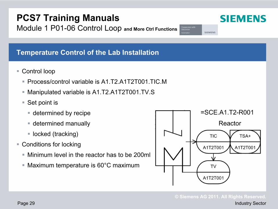
Control loop
Process/control variable is A1.T2.A1T2T001.TIC.M
Manipulated variable is A1.T2.A1T2T001.TV.S
Set point is
determined by recipe
determined manually
locked (tracking)
Conditions for locking
Minimum level in the reactor has to be 200ml
Maximum temperature is 60°C maximum
Temperature Control of the Lab Installation
PCS7 Training Manuals Module 1 P01-06 Control Loop and More Ctrl Functions

© Siemens AG 2011. All Rights Reserved.Industry SectorPage 30
Theory
Structure of step sequences
Designing a sequential control system
Recipe of the lab installation
Step by step instructions
Setting up and editing sequential function charts (SFC)
Connecting SFC and CFC
Testing the SFC
Objective
PCS7 Training Manuals Module 1 P01-07 Sequence Controls

© Siemens AG 2011. All Rights Reserved.Industry SectorPage 31
Alternating sequence of steps and transitions
First step: start step
Final step: end step
Structures:
Unbranched step sequence
Alternative branches
Parallel branches
Impermissible structures:
Uncertain sequence – accessibility not ensured
Partially stuck – internal infinite loop
Totally stuck – no permissible step enable condition
Step sequences can be processed once or cyclically
Structure of Step Sequences
PCS7 Training Manuals Module 1 P01-07 Sequence Controls

© Siemens AG 2011. All Rights Reserved.Industry SectorPage 32
Proven design method for sequence controls
State graphs
Connected, oriented graph
States shown as circles – can be linked to actions
State transitions shown as arrows – subject to transition conditions
Petri nets
Consists of locations and transitions
Locations as circles
Transitions as rectangles/cross bars
Parallel sequences can be mapped
Design of a Sequence Control
PCS7 Training Manuals Module 1 P01-07 Sequence Controls

© Siemens AG 2011. All Rights Reserved.Industry SectorPage 33
First, 350ml are to be drained from educt tank =SCE.A1.T1-B003 into reactor =SCE.A1.T2-R001 and at the same time 200ml from educt tank =SCE.A1.T1-B002 into the reactor =SCE.A1.T2-R002.
When reactor =SCE.A1.T2-R001 is filled, the liquid is to be heated to 25°C with the agitator switched on.
When reactor =SCE.A1.T2-R002 is filled, 150ml from educt tank =SCE.A1.T1-B001 is to be added to reactor =SCE.A1.T2-R002. When this is completed, 10s later the agitator of reactor =SCE.A1.T2-R002 is to be switched on.
When the temperature of the liquid in reactor =SCE.A1.T2-R001 has reached 25°C, the mixture is to be pumped from reactor =SCE.A1.T2-R002 to reactor =SCE.A1.T2-R001.
Now, the mixture in reactor =SCE.A1.T2-R001 is to be heated to 28°C and then drained into product tank =SCE.A1.T3-B001.
Recipe of the Lab Installation
PCS7 Training Manuals Module 1 P01-07 Sequence Controls

© Siemens AG 2011. All Rights Reserved.Industry SectorPage 34
Theory
Concepts of representation
HMI generation in PCS 7
Graphic of the lab installation
Step by step instructions
Generating the operator station (OS) in the SIMATIC Manager
Configuration environment WinCC
Generating pictures using the Graphics Designer
Objective
PCS7 Training Manuals Module 2 P02-01 HMI Generation

© Siemens AG 2011. All Rights Reserved.Industry SectorPage 35
Important aspects of representation
Organization of what is to be represented
Density of representation
Coding
Conspicuousness
Consistency
Basic structure of the display area according to VDI 3699
Flow diagrams
Process control flow diagrams
Process engineering flow diagrams
Basic flow diagram, process diagram, piping and instumentation diagram (P&ID)
Concepts of Representation
PCS7 Training Manuals Module 2 P02-01 HMI Generation
© Siemens AG 2011. All Rights Reserved.Industry SectorPage 36
Picture hierarchy can be derived directly from the plant hierarchy
Setting up a picture in the corresponding levels
Using the block icons of templates
Deriving the block icons from the plant hierarchy
Configuring different OS areas
For example, unit T1 is monitored by Operator 1, T2 to T4 by Operator 2
Monitor configuration
Representation for different resolutions, number and arrangment of monitors
Graphics Designer
Drawing the process images (static elements)
Linking dynamic elements with process variables
HMI Generation in PCS7
PCS7 Training Manuals Module 2 P02-01 HMI Generation

© Siemens AG 2011. All Rights Reserved.Industry SectorPage 37
The hierarchy is to include levels 2 and 3 <<refer to Notes Page for translation of terms below>>
Overview display
Display of all units
Display of the most important information
Abstract
Area display
Representation of a unit
Representation of block icons of motors and valves
Representation based on the P&ID
Graphics of the Lab Installation
PCS7 Training Manuals Module 2 P02-01 HMI Generation

© Siemens AG 2011. All Rights Reserved.Industry SectorPage 38
Theory
Signaling systems
Alarms and indications
Alarm management in PCS7
Step by step instructions
Integrating the monitoring and alarming blocks
WinCC Signalling system
Representation of alarms and warnings on the operator station (OS)
Objective
PCS7 Training Manuals Module 2 P02-02 Alarm Engineering

© Siemens AG 2011. All Rights Reserved.Industry SectorPage 39
Interface between process and operator
Early detection of deviations from the desired state
Target oriented intervention to restore the desired state
Alarm → Display of or report about the occurrence of an event that requires immediate operator action
Message → Display of or report about the occurrence of an event that does not require immediate operator action
Characteristics for selecting alarmsRelevantUnambiguousTimelyPrioritizedUnderstandable
Signaling Systems, Alarms and Indications
PCS7 Training Manuals Module 2 P02-02 Alarm Engineering
© Siemens AG 2011. All Rights Reserved.Industry SectorPage 40
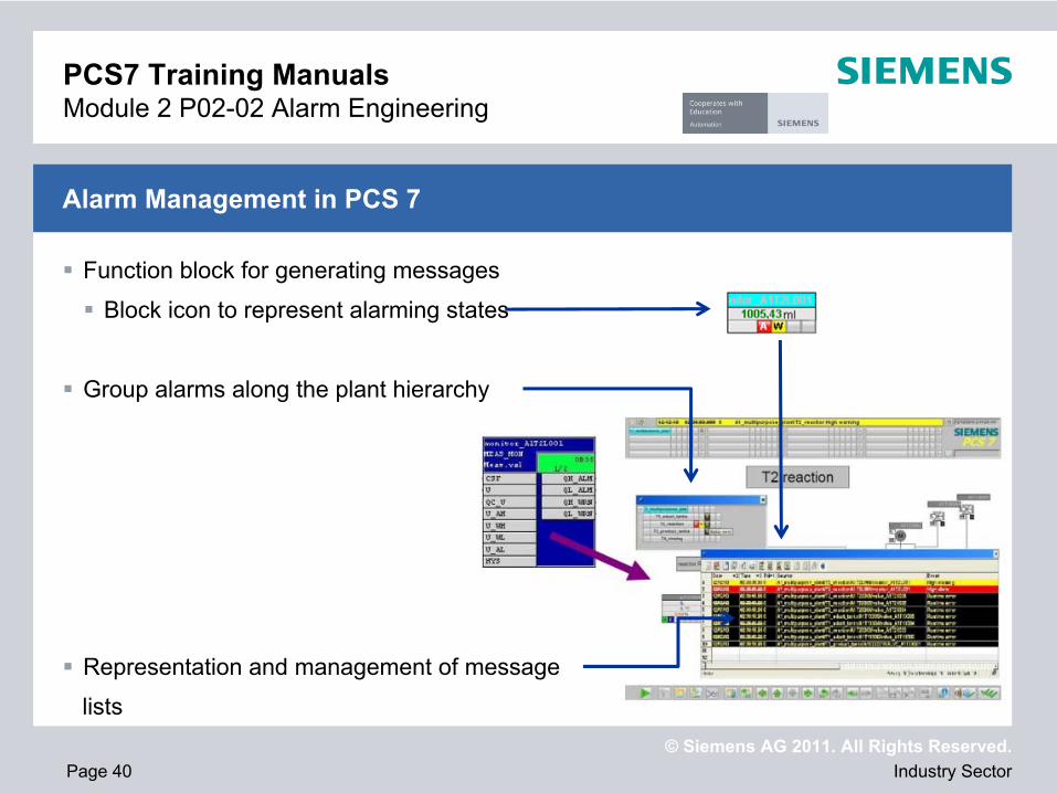
Function block for generating messages
Block icon to represent alarming states
Group alarms along the plant hierarchy
Representation and management of message
lists
Alarm Management in PCS 7
PCS7 Training Manuals Module 2 P02-02 Alarm Engineering

© Siemens AG 2011. All Rights Reserved.Industry SectorPage 41
Monitoring the level
Monitoring the temperature
Using Meas_Mon (FB 65) from the folder Control of the PCS7 Library V71
Monitoring a measured value (analog signal)
Parameters that can be set
Warning limit (high/low)
Alarm limit (high/low)
Representation of the block icon
In unit T2_reaction
Placing and compiling
Alarms for the Lab Installation
PCS7 Training Manuals Module 2 P02-02 Alarm Engineering

© Siemens AG 2011. All Rights Reserved.Industry SectorPage 42
Theory
Design of complex systems
Process tag type
Model
Step by step instructions
Importing plant design data using the import/export wizard
Importing plant design data in the process object view
Duplicating charts by generating process tag types/models
Objective
PCS7 Training Manuals Module 2 P02-03 Importing Plant Design Data

© Siemens AG 2011. All Rights Reserved.Industry SectorPage 43
Three general design principles
Principle of hierarchical arrangement
Plant hierarchy
Principle of modularization
Scope and complexity of function blocks, CFCs and SFCs
Principle of reuse
Process tag types and models
Reuse also implies the following
Use of proven solutions (standards)
Central modifiability
Tested implementation
Design of Complex Systems
PCS7 Training Manuals Module 2 P02-03 Importing Plant Design Data

© Siemens AG 2011. All Rights Reserved.Industry SectorPage 44
Process tag type – CFC - corresponds to the level: individual control unit
Model - entire hierarchies – correspond to the levels Technical installation and unit
Process Tag Types and Models
PCS7 Training Manuals Module 2 P02-03 Importing Plant Design Data
Very individual
Creating types possible
Partial copying
possible

© Siemens AG 2011. All Rights Reserved.Industry SectorPage 45
Selecting similar individual control units
Pumps
A1T1P001, A1T1P002, A1T1P003 and A1T4P001
A1T2P001 and A1T2P002
Valves
A1T1V001, A1T1V002, A1T1V003, .. , A1T1V006
...
Selecting similar technical installations
Containers
A1T1B001, A1T1B002 and A1T1B003
A1T2R001 and A1T2R002
A1T3B001 and A1T3B002
Process Tag Types and Models of the Lab Installation
PCS7 Training Manuals Module 2 P02-03 Importing Plant Design Data

© Siemens AG 2011. All Rights Reserved
Thanks for your attention !
www.siemens.com/sce