pci northeast, full depth deck panels guidelines · pdf filefull depth deck panels guidelines...
TRANSCRIPT

NORTHEAST
A Chapter of thePrecast/Prestressed Concrete Institute
Report Number PCINER-11-FDDP
Full Depth Deck Panels Guidelines
Date Issued April 26, 2011
For Accelerated Bridge Deck Replacement Or Construction
Second Edition

Report No: PCINER-11-FDDP
Copyright © 2011
By Precast/Prestressed Concrete Institute Northeast
Second Edition Printed 2011
All rights reserved. This guide or any part thereof may not be reproduced in any form without the written permission of the Precast/Prestressed Concrete Institute Northeast.
Printed in the U.S.A
Information contain in this work has been obtained from sources believed to be reliable. PCI or its memberships shall not be re-sponsible for any errors, omissions or damages arising out of this information. PCI has published this work with the understanding that PCI is supplying information only. PCI is not rendering engineering or other professional services through this guideline. If such services are required, please seek an appropriate professional.
ii
Report Number PCINER-11-FDDP
Date Issued April 26, 2011
NORTHEAST
A Chapter of thePrecast/Prestressed Concrete Institute
Full Depth Deck Panels Guidelines

Forward
This guideline has been developed for the purposes of promoting a greater degree of uniformity among owners, engi-neers and industry of the Northeast, with respect to planning, designing, fabricating and constructing full depth deck panels for bridge deck replacements or new construction.
In response to needs determined by Northeast Transportation Agencies, and Prestressed Concrete Producers, the PCI Northeast Regional Bridge Technical Committee established a subcommittee comprised of a cross section of its members representing transportation engineers and producers to prepare this guide. Contributors were:
Deck Panel Sub Committee:Rita Seraderian, PCI Northeast Executive Director (PCINE); Belmont, MA Michael P. Culmo, CME Associates, Inc.; East Hartford, CT Jason Tremblay, New Hampshire DOT; Concord, NH Eric Calderwood, Principal, Calderwood Engineering, Richmond, ME Vartan Sahakian, Commonwealth Eng. & Consult.; Providence, RI Ed Barwicki, Lin Associates; Boston, MA Maura Sullivan, Massachusetts DOT; Boston, MA Edmund Newton, Massachusetts DOT; Boston, MA Darren Conboy, Jacobs Engineering; Boston, MA Scott Harrigan, Fort Miller Group; Schuylerville, NY Eric Schaffrick, Dailey Precast; Shaftsbury, VT
The PCI-NE Bridge Tech Committee:Jim Braun, Blakeslee Prestress; Branford, CT Joseph Cancelliere, Connecticut DOT; Newington, CT Lee Edwards, Dailey Precast; Shaftsbury, VT Joe Carrara, J. P. Carrara & Sons; Middlebury, VT Ernie Brod, J. P. Carrara & Sons; Middlebury, VT Michael Kane, Kane Assoc.; Bolton, MA Robert Bulger, Maine DOT; Augusta, ME Alex Bardow, Massachusetts DOT, Boston, MA David Scott, New Hampshire DOT; Concord, NH Duane Carpenter, New York State DOT; Albany, NY Michael Twiss, New York State DOT; Albany, NY Mike Savella, Rhode Island DOT; Providence, RI Joel Dickerson, Oldcastle Precast; Rehoboth, MA Chris Fowler, Oldcastle Precast; Rehoboth, MA Tim Fillbach, Vermont Agency of Transportation; Montpelier, VT
iii
Report Number PCINER-11-FDDP
NORTHEAST
A Chapter of thePrecast/Prestressed Concrete Institute
Date Issued April 26, 2011
Full Depth Deck Panels Guidelines—Appendix A


Forward iii
Introduction 2
Case Study–Sanborton-Belmont, NH Project 2
Case Study– I-84/Rt. 8, Waterbury, CT Project 2
Guidelines 3-13
SECTION 1 General 3
1.1 Structure Types 3
SECTION 2 Materials 3-4
2.1 Concrete 3
2.2 Mild Reinforcement 3
2.3 Prestressing Strand 3
2.4 Post-Tensioning Duct 4
2.5 Post Tensioning Anchorage Devices 4
2.6 Grout for Transverse Shear Keys, Shear
Connector Pockets, and Beam Haunches 4
2.7 Grout for Post-Tensioning Ducts 4
SECTION 3 Design Requirements 5-10
3.1 General 5
3.2 Framing Geometry and Layout 5
3.3 Concrete Design Strength 5
3.4 Strand Pattern 6
3.5 Allowable Concrete Stresses 6
3.6 Transverse Flexure Design 6
3.7 Panel Overhang Design 6
3.8 Design for Handling 6
3.9 Longitudinal Distribution Design within each FDDP 7
3.10 Longitudinal Post-Tensioning 7
3.10.1 Losses in Post Tensioning 8
3.10.2 Anchorage Zone Design 8
3.11 Composite Deck Design 8
3.12 Closure Pours 9
3.13 Curved Bridge Issues 10
SECTION 4 Construction 10-13
4.1 Construction Sequence 10
4.2 Deck Elevations 11
4.3 Casting Tolerances 12
4.4 Vertical Adjustment 12
4.5 Horizontal Adjustment 13
4.6 Parapets, Curbs, and Railings 13
Appendix A (Details) 14-29
Typical Layout Plan; Skew Between 0 and 15 Degrees 14
Typical Layout Plan; Skew Greater Than 15 Degrees 15
Typical Panel Plan 16
Typical Panel Plan; Oversize Blockout 17
Transverse Shear Key Details 18
Leveling Device Details 19
Shear Connector Blockout Details 20
Bulb Tee Beam Attachment Details 1 21
Bulb Tee Beam Attachment Details 2 22
Deck Replacement Attachment Details 23
Deck Overhang & Parapet Details 24
Post Tensioning Duct Details 25
Post Tensioning Anchorage Details 26
Closure Pours at Deck Ends 27
Roadway Crown Detail 28
Recommended Tolerances 29
References and Resources 30
Contents
1
Report Number PCINER-11-FDDP
Date Issued April 26, 2011
NORTHEAST
A Chapter of thePrecast/Prestressed Concrete Institute
Full Depth Deck Panels Guidelines

Rt. 3 Over Winnisquam LakeSanborton-Belmont, NH Project
New Hampshire Department of Transporta-tion (NHDOT) used full depth deck panels for the first time to rebuild the Mosquito Bridge on Route 3 over the Winnisquam Lake. This method was chosen to reduce construction related traffic backups dur-ing peak vacation time. The project was a four span 468 foot long by 52' bridge. The project begin in March 2006 and was com-pleted in phases on September 18, 2006. After the success of this project, NHDOT has built several other Deck Panel projects.
Owner/Designer: State of New Hampshire, Department of Transportation
Design/Construction/Inspection Team: Jason Tremblay/Jason Leavitt, NHDOT, Bureaus of Bridge Design and Construction
General Contractor: Alvin J. Coleman & Son, Inc., Conway, New Hampshire
Precaster: J. P. Carrara & Sons, Inc., Middlebury, Vermont
I-84/Rt. 8 Interchange Waterbury, CT
The Waterbury project was the first project to use the PCINE Full Depth Deck Panel details. The six span single lane I 84/ Route 8 Interchange in Waterbury, CT has been in service since 1991 making 2011 it’s 20th year of service. This project was built in 42 days with no contruction problems. Use of membrane waterproofing and asphalt wear-ing surface resulted in no leakage through joints. After 20 years of service the bridge is in excellent condition.
Owner/Designer: State of Connecticut, Department of Transportation
Design/Construction/Inspection Team: Michael Culmo CME Associates (with CTDOT at the time of Design)
Precaster: Blakeslee Prestress, Branford, CT
Introduction
This guide is the current State of the Art report developed by the PCI Northeast Bridge Technical Committee on the use of Precast Concrete Full Depth Deck Panels to accelerate the construction of bridge deck projects. This system is used to replace bridge decks during off-peak traffic hours and can be a good solution in terms of minimizing traffic disruption.
Precast components produced off-site can be quickly assembled, and can reduce design time, cost, minimize forming, minimize lane closure time and/or possibly the need for a temporary bridge.
In 2002, the PCI Technical Committee developed a report for full depth deck panels. This is the second edition of this report and has been expanded to include additional information that will be useful to designers.
This guide is not intended as a stand-alone document and does not supersede the AASHTO specifications and/or States Design Standards.
2
Report Number PCINER-11-FDDP
Date Issued April 26, 2011
NORTHEAST
A Chapter of thePrecast/Prestressed Concrete Institute
Full Depth Deck Panels Guidelines

Guidelines CommentarySECTION 1 General
Precast Full Depth Deck Panels (FDDP) may be used for new construction or for replacement of existing deck slabs.
This guideline is not for use on partial depth precast deck panels that are intended to be overtopped with a reinforced concrete pour. Please refer to additional guidance on partial depth deck panels at www.pcine.org.
1.1 Structure TypesPrecast FDDP can be used on virtually any structure that is currently designed with a cast in place deck.
The following is a list of typical structure types that can be designed with Precast Prestressed Concrete Full Depth Deck Panels:
Prestressed Concrete Stringers•Steel Stringers•Steel Girder/Floorbeam Systems•Steel Truss Systems•Long Span Suspension and Cable Stayed Systems•
FDDP can be used on straight, skewed and curved bridges.
SECTION 2 Materials
2.1 ConcreteAll mild reinforcement shall conform to the requirements of ASTM A615 and shall be epoxy coated in accordance with ASTM D3963.
Normal deck slab concrete may be used; however, this limits the use of prestressing in the pieces. The designer should take advantage of high strength and high quality concrete that is normally used in a precast plant.
2.2 Mild Reinforcement All mild reinforcement shall conform to the requirements of ASTM A615 and shall be epoxy coated in accordance with ASTM D3963.
FDDP systems have been built with transverse prestressing (prestressed); however, some mild reinforcement will be required within the panel (distribution steel, slab overhang steel, etc.).
FDDP systems may also be designed with only mild reinforcement.
2.3 Prestressing StrandThe seven wire strand for pre-tensioning shall conform to the requirements of ASTM A416, Grade 270, low relaxation, and shall be tensioned to the allowable stresses outlined in the AASHTO specifications.
Prestressing strand may be used for flexural resistance of the deck panels.
A maximum of four 0.6 inch or 0.5 inch diameter strand is typically used with a 2 inch nominal post tensioning duct. If flat slab ducts are used, it is recommended that a maximum of four ½ inch strand be used.
3
Report Number PCINER-11-FDDP
NORTHEAST
A Chapter of thePrecast/Prestressed Concrete Institute
Date Issued April 26, 2011
Full Depth Deck Panels Guidelines

2.4 Post-Tensioning DuctThe use of 2 inch nominal diameter duct is recommended. 2 inch diameter duct provides ample room for the recom-
mended post-tensioning strand and erection tolerances at the duct connections. Flat duct can also be used provided that mandrels are used during casting to maintain the geometry of the duct.
2.5 Post Tensioning Anchorage DevicesAnchorage devices should be selected to provide the required concrete cover.
For most deck panels, a four-strand flat anchorage assembly will provide the proper cover. This assembly can be used with the 2 inch nominal ducts.
The anchorage device should normally be placed at mid-depth of the panel.
In cases where the top cover cannot be achieved, the anchorage device can be lowered slightly to provide the required cover.
Anchorage devices should normally be kept a minimum horizontal distance of 18 inch from panel edges and shear connector blockouts.
Smaller dimensions can be used provided that the anchorage forces are accounted for in the design of the panel.
2.6 Grout for Transverse Shear Keys, Shear Connector Pockets, and Beam Haunches
Grout for transverse shear keys, shear connector pockets and beam haunches should meet the following general requirements:
Non-shrink•Flowable•Moderate strength (5ksi)•Low permeability•
Field mixed grouts should not be used. The use of pre-qualified pre-bagged grouts is preferred.
Proportioned mixed grouts in general do not provide adequate quality and durability. State agency prequalified grouts should be used if required.
2.7 Grout for Post-Tensioning DuctsGrout for post tensioning ducts shall be specifically formulated to fill post tensioning systems. Pre-bagged grouts should be used.
4
Report Number PCINER-11-FDDP
NORTHEAST
A Chapter of thePrecast/Prestressed Concrete Institute
Date Issued April 26, 2011
Full Depth Deck Panels Guidelines

SECTION 3 Design Requirements
3.1 GeneralIn general, the design of full depth deck panels should follow the requirements of the AASHTO LRFD Bridge Design Specifications.
The empirical design method outlined in Section A. 9.7.2 is not applicable to precast deck panels. The design of transverse shear keys and longitudinal B. post-tensioning shall conform to Section 9.7.5
3.2 Framing Geometry and LayoutPanels should be laid out perpendicular to the main supporting members. The main reinforcement (herein referred to as transverse reinforcement) should run along the length of the panel, generally transverse to the main supporting members. Distribution reinforcement shall consist of post-tensioning strand running the length of the deck, generally parallel to the main supporting members.
The terminology for this document is based on construction of typical stringer bridges where the FDDP are installed perpendicular to the stringers. Construction of other systems such as floorbeam bridges may result in panels that are running parallel with the roadway. In this case, the designer should account for the adjustment in the terminology.
Deck panels can be set to match the cross slope of the finished roadway. For crowned roadways, a small closure pour should be incorporated into the design at the crown. For narrow roadways, it may be possible to install the panels level and crown the wearing surface.
Most states layout bridge framing along the cross slope of the roadway, which leads to a sloped deck panel. Roadway crowns are always an issue in precast FDDP bridges. It is very difficult to construct precast FDDP with a built-in crown, especially if pretensioned prestressing is used. A small closure pour has proven to be a very effective means of accommodating the crown of the deck without adding significant time to the construction of the bridge. Often, this closure pour is completed at the same time as the end closure pours or parapet placement.
For bridges with minor skews as shown in the details, the panels can be designed to follow the skew of the bridge. For larger skews, the panels should be laid out in a squared pattern.
3.3 Concrete Design StrengthThe design of deck panels without prestressing should be based on a minimum concrete compressive strength (f’c) of not less than 5 ksi.
For designs with prestressing, the recommended concrete compressive strength is 6 ksi. The compressive strength of the concrete at the time of transfer (f’ci) should not be less than 4 ksi.
5
Report Number PCINER-11-FDDP
NORTHEAST
A Chapter of thePrecast/Prestressed Concrete Institute
Date Issued April 26, 2011
Full Depth Deck Panels Guidelines

3.4 Strand PatternTypical strand patterns are laid out with zero eccentricity in order to resist the positive and negative moments in bridge decks.
This is based on typical design equations for slabs in the AASHTO specifications where the maximum positive moment is equal to the maximum negative moment.
Concentric prestress is also desirable in order to minimize the cambering of the panel after casting.
3.5 Allowable Concrete StressesThe allowable stresses in the deck panels shall conform to the AASHTO specifications.
3.6 Transverse Flexure DesignDeck panels may be designed with mild reinforcement, prestressing strand, bonded post-tensioning strand, or combinations of each.
In many cases, the design of interior bays can be handled with mild reinforcing and/or prestressing. Some projects have been completed with post-tensioning systems; however, costs for large amounts of transverse stressing and grouting can be prohibitive.
Moments for design shall be based on the AASHTO specifications for concrete deck slabs.
In general, panels with spans of 10 feet or less can be designed with only mild reinforcement resisting the flexural moments. Prestressing may be used for longer spans.
3.7 Panel Overhang DesignThe design of the panel overhangs shall be in accordance with the AASHTO specifications.
The barrier weight and impact loads have a significant effect on the overhang design. The panel reinforcing needs to be designed to accommodate these forces.
Special attention should be given to the design of the panel overhang with regard to the development of prestressing strand. If the strand cannot be developed within the panel overhang, a design using mild reinforcement or post-tensioning in conjunction with prestressing may be necessary in order to accommodate the overhang moments.
It is not desirable to have a large bending moment applied within the transfer and development zone of the prestressed component. In many cases, the maximum slab moment in the overhang occurs at the face of the curb, which is usually very close to the end of the precast panel. Mild reinforcement is often used to handle the slab overhang moments near the ends of the panels.
3.8 Design for HandlingDesign lifting hardware and panel reinforcement according to the provisions in Chapter 5 of the PCI Design Handbook (seventh edition). The criteria for “no discernable cracking” should be followed.
This provision is based on the fact that during erection, every other leveling device will be in contact with the girders prior to the leveling of the panels.
The panels shall also be checked for placement stresses assuming that the panel is supported on every other girder. The design of the prestress for handling will be the responsibility of the contractor.
Fabricators and contractors normally determine lifting points based on their handling equipment. The amount of prestress will vary based on the lifting methods employed. The design and review of this prestressing should be treated as a working drawing submission since the prestress is being used for a temporary condition.
6
Report Number PCINER-11-FDDP
NORTHEAST
A Chapter of thePrecast/Prestressed Concrete Institute
Date Issued April 26, 2011
Full Depth Deck Panels Guidelines

3.9 Longitudinal Distribution Design within each FDDPReinforcement for distribution shall be comprised of mild reinforcement. The design of distribution reinforcement should be according to the AASHTO specifications based on a slab with mild reinforcement. The mild reinforcement does not need to pass through the joints between the deck panels.
This steel is to be placed within each panel. The spacing of the steel will need to be adjusted to avoid blockouts and provide proper cover around blockouts. The designer should detail a bar layout for each panel.
3.10 Longitudinal Post-TensioningThe design of transverse joints and longitudinal post-ten-sioning shall be in accordance with AASHTO Section 9.7.5
Post-tensioning combined with a grouted shear key should be used to provide continuity between deck panels. This post-tensioning should be located at mid-depth in the units and should run the entire length of the bridge or between closure pours.
Research has shown that moderate post-tensioning com-bined with a grouted shear key is the best way to provide continuity between full depth panels.
For continuous spans, the designer should design for additional prestress to overcome the service load tensile stress due to negative composite dead load and live load moments to achieve an effective minimum prestress of 0.250 ksi under all service loading conditions.
The minimum final post-tensioning force per duct and the minimum effective prestress shall be shown on the plans, as well as a sequence for stressing the ducts (generally starting at the center and working to the outside).
The plans should note the assumptions used to develop the post-tensioning force including the assumptions used for loss calculations
The project specifications should include requirements for submission of calculations for the design of the post-tensioning system. These calculations should account for the actual system and ducts that are proposed.
7
Report Number PCINER-11-FDDP
NORTHEAST
A Chapter of thePrecast/Prestressed Concrete Institute
Date Issued April 26, 2011
Full Depth Deck Panels Guidelines

3.10.1 Losses in Post TensioningLosses due to elastic shortening, anchorage set and fric-tion in the ducts should be accounted for in the design of the post-tensioning.
Long-term losses in longitudinal post-tensioning stress due to creep and shrinkage need not be accounted for in the design.
Most designers do not account for long-term losses in the deck panel on steel beam bridges. This is due to several reasons:
The amount of post-tensioning stress specified A. is considered to be somewhat arbitrary and high; therefore, minor losses in post-tensioning are considered acceptable and insignificant. The design of composite beams accounts for some B. creep by using a modified modular ratio for long-term loads.
3.10.2 Anchorage Zone DesignThe design of the reinforcement in the anchorage zones shall conform to the AASHTO specifications.
The design of the local zone reinforcement is the responsibility of the anchorage device manufacturer.
The local zone reinforcement is highly dependent on the geometry of the anchorage device, which is under the control of the device manufacturer.
The design of the general zone reinforcement is the responsibility of the designer.
The general zone reinforcement is affected by the ge-ometry of the panel, which is under the control of the designer.
3.11 Composite Deck DesignDeck panels should be made composite with the supporting members.
Composite action is achieved with shear connectors placed in blockouts in the panel. Shear connectors shall consist of welded studs or hooked reinforcing steel on concrete girders.
The effectiveness of using welded stud shear connec-tors on steel beams has been verified through several research projects. The design of the shear connectors can be based on the requirements for cast-in-place slabs. A embedded steel plate can be used in concrete beams to achieve the same effect. This has also been verified through research.
The use of hooked reinforcing steel for shear transfer has also been studied. The AASHTO provisions for horizontal shear design are appropriate for this design.
8
Report Number PCINER-11-FDDP
NORTHEAST
A Chapter of thePrecast/Prestressed Concrete Institute
Date Issued April 26, 2011
Full Depth Deck Panels Guidelines
Spacing of shear connector blockouts shall be kept at approximately 2 feet on center where possible. The de-sign for variable horizontal shear can be accommodated by varying the number of shear connectors per blockout.
The 2 foot maximum shear connector spacing has been in the AASHTO specifications for many years. Recent research has shown that the spacing can be increased to 4 feet without any reduction in composite action. This can only be achieved if a confinement pocket is provided such as a steel tube or confinement reinforcement. Larger diameter shear studs have been tested and been found to perform adequately; however, they may not be readily available. Large spacing of shear connectors will require a large number of shear connectors per pocket, which may become problematic. In most cases, limiting the blockout spacing to 2 foot maximum will limit the number of shear connectors to a reasonable number.
Special panels with larger reinforced blockouts may be required for continuous girder bridges.
These special panels should only be used where neces-sary. They can be combined with regular panels with nominally spaced shear connector blockouts.
The design of short span and continuous steel girders for ulti-mate flexural strength typically requires a significant amount of shear connectors from the points of maximum moment to the adjacent supports. The number of studs is primarily con-trolled by the beam spacing (not the necessarily the beam size). On short span bridges, this distance can be very short, which will necessitate very close shear connector spacing.
Large pockets can disrupt the spacing of panel reinforcement. Therefore it is desirable to run the reinforcement through the large pockets (see typical details).
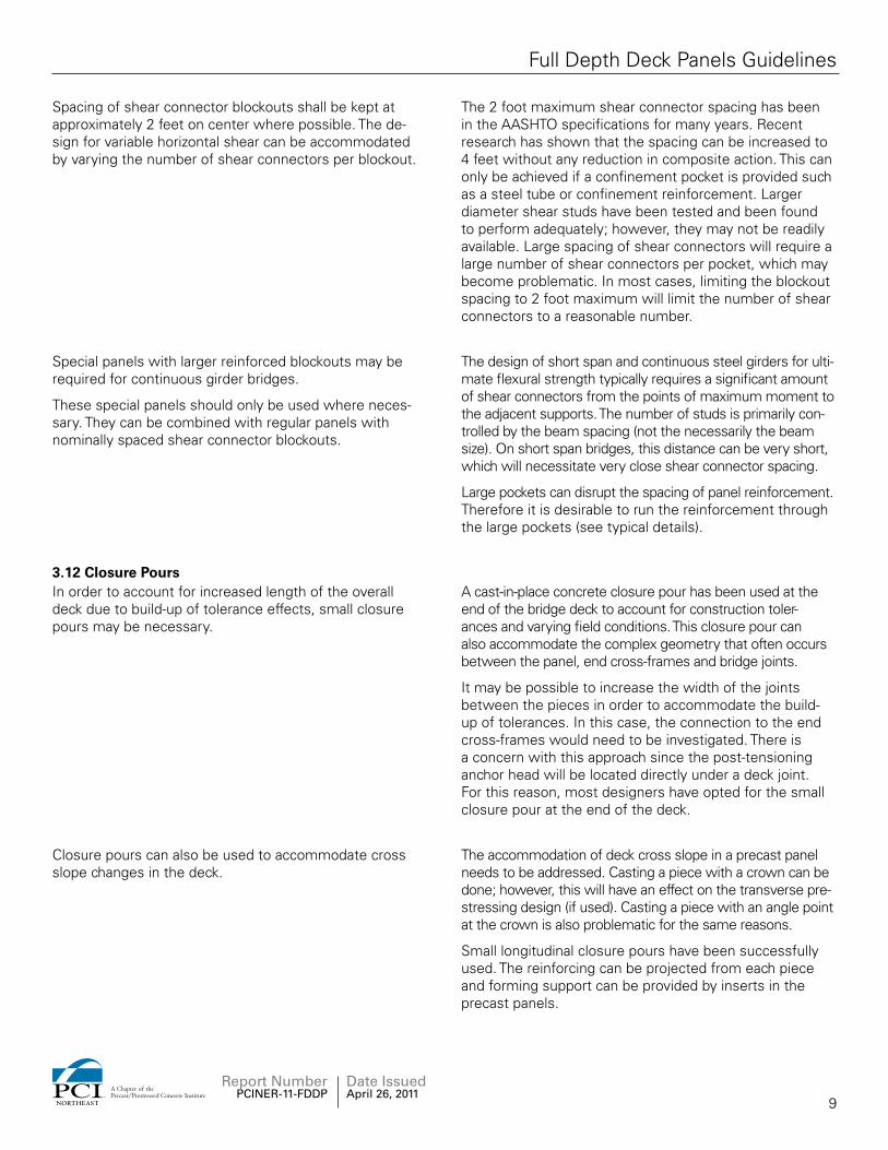
3.12 Closure PoursIn order to account for increased length of the overall deck due to build-up of tolerance effects, small closure pours may be necessary.
A cast-in-place concrete closure pour has been used at the end of the bridge deck to account for construction toler-ances and varying field conditions. This closure pour can also accommodate the complex geometry that often occurs between the panel, end cross-frames and bridge joints.
It may be possible to increase the width of the joints between the pieces in order to accommodate the build-up of tolerances. In this case, the connection to the end cross-frames would need to be investigated. There is a concern with this approach since the post-tensioning anchor head will be located directly under a deck joint. For this reason, most designers have opted for the small closure pour at the end of the deck.
Closure pours can also be used to accommodate cross slope changes in the deck.
The accommodation of deck cross slope in a precast panel needs to be addressed. Casting a piece with a crown can be done; however, this will have an effect on the transverse pre-stressing design (if used). Casting a piece with an angle point at the crown is also problematic for the same reasons.
Small longitudinal closure pours have been successfully used. The reinforcing can be projected from each piece and forming support can be provided by inserts in the precast panels.
9
Report Number PCINER-11-FDDP
NORTHEAST
A Chapter of thePrecast/Prestressed Concrete Institute
Date Issued April 26, 2011
Full Depth Deck Panels Guidelines

3.13 Curved Bridge IssuesThe post-tensioning ducts on curved bridges should fol-low the curvature of the roadway.
For curved bridges, the pieces can be cast in a trapezoidal shape so that the joints between deck panels are radial. The post-tensioning can be run along the curve. For large radius curves, it is acceptable to run the post-tensioning duct straight within each panel combined with small angle points at the hand hole splice locations.
The design of the longitudinal post-tensioning should take into account the losses due to friction in the post-tension-ing ducts due to curvature.
The amount of friction losses in a curved duct can be-come significant. It may be necessary to specify jacking the post-tensioning strand from each end in order to overcome the friction losses in the ducts.
SECTION 4 Construction
4.1 Construction SequenceIn order to avoid inducing undesirable stresses in the girders, the sequence of construction for precast concrete deck panels shall be such that the longitudinal post-tensioning is accomplished after the transverse panel joints have been grouted and before the panel has been made composite with the girders.
If the post-tensioning is applied after the deck is made composite with the beams, the post-tensioning will induce a positive moment into the beam. The construction sequence outlined in the detail sheets ensures that this will not occur.
The following sequence of construction should be includ-ed on the plans:
Clean surfaces of shear keys. 1. Follow State specifications. High-pressure water blasting can be used for this cleaning. Sand blasting should be avoided if there is coated projecting reinforcement.
Preset leveling bolts to anticipated height2.
Place all precast deck panels on girders in a span.3. Setting of the panels high and lowering them into position will require less torque.
Adjust leveling devices on deck panels to bring 4. panels to grade.
All leveling bolts shall be torqued to approximately 5. the same value (20 percent maximum deviation).
Install longitudinal post-tensioning strand (un-ten-6. sioned) in ducts and seal joints in ducts between deck panels.
The FHWA manual entitled “Post-Tensioning Tendon Installation and Grouting Manual” should be followed for this operation.
Place a flowable non-shrink grout in all transverse 7. joints. The grout shall be rodded or vibrated to en-sure all voids are filled.
10
Report Number PCINER-11-FDDP
NORTHEAST
A Chapter of thePrecast/Prestressed Concrete Institute
Date Issued April 26, 2011
Full Depth Deck Panels Guidelines

After the grout in the transverse joints has attained 8. a strength of 1000 psi (based on grout manufac-turers’ recommendations), the longitudinal post-tensioning strands may be stressed. The contractor shall determine the jacking force required to achieve the minimum final post-tensioning force shown on the plans accounting for all losses.
The interim strength of the transverse joint grout may need to be adjusted based on the level of post-tensioning stress specified.
Grout post-tensioning ducts.9. The FHWA manual entitled “Post-Tensioning Tendon Installation and Grouting Manual” should be followed for this operation.
Install shear connectors in all blockouts.10.
Form haunches between the top of the girders and 11. the bottom of the deck panels.
Haunch forms can be set before setting panels
Grout all haunches and shear connector blockouts 12. with a flowable non-shrink grout.
Cast end closure pours.13. Closure pours can be designed for lower initial concrete strength, which would allow for earlier opening of the bridge. Final strength of the closure pour concrete should follow State standards for deck panels.
Cast parapets and/or sidewalks.14.
Place overlay (if required) and open Bridge15. No vehicles or heavy equipment should be allowed on the panels until the installation sequence is complete and all materials have achieved adequate strength.
4.2 Deck ElevationsThe plans should include the elevations of each panel (generally each corner of each panel) based on the re-quired elevation of the panels after all panels are placed on a span. The following equation can be used to deter-mine the deck elevations:
A = B – W + C
A = Deck Elevation shown on plans
B = Finished Elevation of Deck
W = Thickness of Wearing Surface
C = Deflection due to Composite Loads
These elevations are the anticipated elevations just after the erection of the panels. The deflection due to compos-ite loads shall account for all loads applied after the deck panels have been placed, including, but not limited, to the wearing surface, parapets, sidewalks and railings.
11
Report Number PCINER-11-FDDP
NORTHEAST
A Chapter of thePrecast/Prestressed Concrete Institute
Date Issued April 26, 2011
Full Depth Deck Panels Guidelines

4.3 Casting TolerancesTolerances for casting panels shall be shown on the plans or in the specifications.
Recommended tolerances for precast deck panels have been developed by the committee. It is very important to have many of the tolerances measured from a common working point. Center-to-center measurements can lead to a buildup of measuring errors and unacceptable results.
Special attention should be given to the location of the longitudinal post-tensioning ducts.
The ducts should be oversized in order to accommodate the specified tolerances.
The location of the post-tensioning ducts requires the most stringent tolerances. Misalignment of the ducts can cause significant problems in the field. It is common for post-tensioning ducts to flex during concrete placement. For this reason, it is recommended that the duct be properly secured to the deck reinforcing or stiffened by a reinforcing bar. Mandrels can also be used to position the duct and prevent deformation during casting.
4.4 Vertical AdjustmentLeveling bolts should be used to adjust the grade of the deck panels after placement.
The most common size of leveling bolt is 1 inch diameter. The bolts should be detailed so that they can be removed easily after grout placement. The device should also be recessed so that the top surface can be sealed with grout after bolt removal. The details included in this guide are the most common type used.
The design of leveling devices is typically accomplished by the designer. If bolts are used, each bolt should be able to resist two times the tributary dead load of the panel. The design of the bolts should also account for the cross slope of the roadway.
Designers should show this detail, but allow the contractor to substitute alternate devices, provided they can meet the criteria described in this section. The cross slope of the roadway will induce bending in the bolts. In this case, the bolts should be designed for the bending or canted to match the cross slope of the road.
These bolts serve two purposes. They allow for grade adjustment in the field after deck placement, and they also provide proper dead load distribution to each girder. For this reason, there should be the same number of leveling bolts over each beam (typically two per beam).
The plans or specifications should note that each bolt should be torqued to approximately the same value so that there is approximately equal load on each leveling bolt.
The amount of torque on each bolt should be within 20% of an average torque that is determined in the field. This value offers sufficient uniform distribution. Minor variation in each bolt load can be overcome by distribution through the beam cross-frames.
12
Report Number PCINER-11-FDDP
NORTHEAST
A Chapter of thePrecast/Prestressed Concrete Institute
Date Issued April 26, 2011
Full Depth Deck Panels Guidelines

4.5 Horizontal AdjustmentThe transverse joints between deck panels should have a nominal width of ½ inch. The width of this joint may be adjusted in the field by +3/8 inch to account for casting tolerances.
Casting tolerances such as panel width and sweep can lead to a build-up of deck length. This buildup of length has been referred to as dimensional growth. If ten panels that are exactly 8 feet wide are laid side by side, the overall deck length would measure somewhat over 80 feet due to the uneven seating of the panels. The width of the joints between each deck panel can be used to account for this effect. For this reason, the allowable width of the panel joints should be closely related to the specified fabrication tolerances. The value of ½ inch + 3/8 inch has been found to be an adequate joint width variation to account for these effects.
It is not necessary to design the deck layout to account for dimensional growth of the panels. If the variation in joint width does not adequately account for the tolerance, the closure pours at the ends of the spans can be used to make up any minor differences.
4.6 Parapets, Curbs, and RailingsCast-in-place parapets or curbs combined with railings should normally be used for the final traffic barrier.
Cast-in-place parapets and curbs offer a number of benefits to the finished structure:
They assist with connecting the adjacent deck panels •in the deck overhang region. They provide a means of sealing the gutterline and •prevent water leakage through the parapet. Most cast-in-place barriers are crash-tested. There are •very few crash-tested precast barrier systems. The cast-in-place parapet or curb can be used to encase •the ends of the deck panels.
There have been concerns from several agencies that the construction of a cast-in-place barrier system will increase the time for construction. This is true; however, for very rapid deck placement projects, the final barrier can be constructed after the bridge is opened to traffic. Temporary precast concrete barriers can be used in the shoulders. The permanent barrier can then be constructed behind the temporary barrier.
Encasing the edge of the deck panels offers a number of benefits. If the panels are prestressed transversely, the edge of the panels will have numerous locations where the prestressing strand are cut and patched. Long-term deterioration of the patched strand ends is a concern. The ends of the panels can also be uneven due to casting tolerances. By casting a concrete curb or parapet over the deck end, a uniform deck edge can be produced that will enhance the appearance of the completed deck.
13
Report Number PCINER-11-FDDP
NORTHEAST
A Chapter of thePrecast/Prestressed Concrete Institute
Date Issued April 26, 2011
Full Depth Deck Panels Guidelines

See Detail FDDP-14.
Typical Layout PlanSkew Between 0 and 15 DegreesDetail FDDP – 1
14
Report Number PCINER-11-FDDP
NORTHEAST
A Chapter of thePrecast/Prestressed Concrete Institute
Date Issued April 26, 2011
Full Depth Deck Panels Guidelines—Appendix A

See Detail FDDP-14.
Typical Layout PlanSkew Greater Than 15 Degrees
Detail FDDP – 2
15
Report Number PCINER-11-FDDP
NORTHEAST
A Chapter of thePrecast/Prestressed Concrete Institute
Date Issued April 26, 2011
Full Depth Deck Panels Guidelines—Appendix A

See Detail FDDP-13 for details.
See Detail FDDP-6See Detail FDDP-12
See Detail FDDP-7
See Detail FDDP-6
See Detail FDDP-12See Detail FDDP-7
see Detail FDDP-6.
Typical Panel PlanDetail FDDP – 3
16
Report Number PCINER-11-FDDP
NORTHEAST
A Chapter of thePrecast/Prestressed Concrete Institute
Date Issued April 26, 2011
Full Depth Deck Panels Guidelines—Appendix A

See Detail FDDP-12 for details.
see Detail FDDP-6.
See Detail FDDP-6See Detail FDDP-12
See Detail FDDP-7
See Detail FDDP-6
See Detail FDDP-12See Detail FDDP-7
Typical Panel PlanOversize Blockout
Detail FDDP – 4
17
Report Number PCINER-11-FDDP
NORTHEAST
A Chapter of thePrecast/Prestressed Concrete Institute
Date Issued April 26, 2011
Full Depth Deck Panels Guidelines—Appendix A

Transverse Shear Key DetailsDetail FDDP – 5
18
Report Number PCINER-11-FDDP
NORTHEAST
A Chapter of thePrecast/Prestressed Concrete Institute
Date Issued April 26, 2011
Full Depth Deck Panels Guidelines—Appendix A

Leveling Device DetailsDetail FDDP – 6
19
Report Number PCINER-11-FDDP
NORTHEAST
A Chapter of thePrecast/Prestressed Concrete Institute
Date Issued April 26, 2011
Full Depth Deck Panels Guidelines—Appendix A

Shear Connector Blockout DetailsDetail FDDP – 7
20
Report Number PCINER-11-FDDP
NORTHEAST
A Chapter of thePrecast/Prestressed Concrete Institute
Date Issued April 26, 2011
Full Depth Deck Panels Guidelines—Appendix A

Bulb Tee Beam Attachment Details 1
Detail FDDP – 8
21
Report Number PCINER-11-FDDP
NORTHEAST
A Chapter of thePrecast/Prestressed Concrete Institute
Date Issued April 26, 2011
Full Depth Deck Panels Guidelines—Appendix A

Bulb Tee Beam Attachment Details 2Detail FDDP – 9
22
Report Number PCINER-11-FDDP
NORTHEAST
A Chapter of thePrecast/Prestressed Concrete Institute
Date Issued April 26, 2011
Full Depth Deck Panels Guidelines—Appendix A

Deck Replacement Attachment Details
Detail FDDP – 10
23
Report Number PCINER-11-FDDP
NORTHEAST
A Chapter of thePrecast/Prestressed Concrete Institute
Date Issued April 26, 2011
Full Depth Deck Panels Guidelines—Appendix A
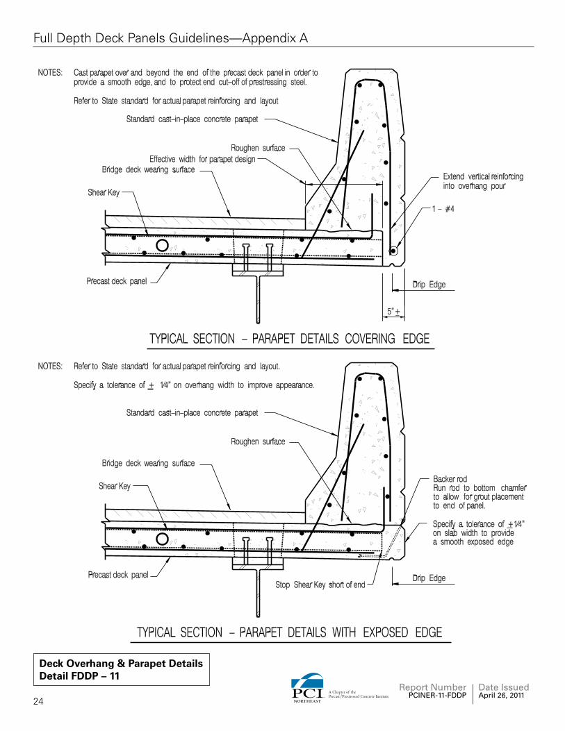
Deck Overhang & Parapet DetailsDetail FDDP – 11
24
Report Number PCINER-11-FDDP
NORTHEAST
A Chapter of thePrecast/Prestressed Concrete Institute
Date Issued April 26, 2011
Full Depth Deck Panels Guidelines—Appendix A

Post Tensioning Duct DetailsDetail FDDP – 12
25
Report Number PCINER-11-FDDP
NORTHEAST
A Chapter of thePrecast/Prestressed Concrete Institute
Date Issued April 26, 2011
Full Depth Deck Panels Guidelines—Appendix A

Post Tensioning Anchorage DetailsDetail FDDP – 13
26
Report Number PCINER-11-FDDP
NORTHEAST
A Chapter of thePrecast/Prestressed Concrete Institute
Date Issued April 26, 2011
Full Depth Deck Panels Guidelines—Appendix A

Closure Pours at Deck EndsDetail FDDP – 14
27
Report Number PCINER-11-FDDP
NORTHEAST
A Chapter of thePrecast/Prestressed Concrete Institute
Date Issued April 26, 2011
Full Depth Deck Panels Guidelines—Appendix A

Roadway Crown DetailDetail FDDP – 15
28
Report Number PCINER-11-FDDP
NORTHEAST
A Chapter of thePrecast/Prestressed Concrete Institute
Date Issued April 26, 2011
Full Depth Deck Panels Guidelines—Appendix A
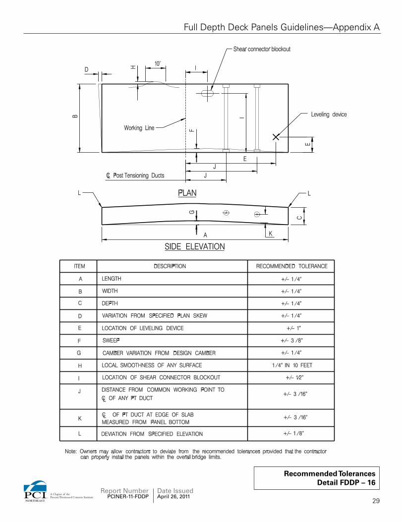
Recommended TolerancesDetail FDDP – 16
29
Report Number PCINER-11-FDDP
NORTHEAST
A Chapter of thePrecast/Prestressed Concrete Institute
Date Issued April 26, 2011
Full Depth Deck Panels Guidelines—Appendix A

ReferencesAASHTO LRFD Bridge Design Specifications, 5th Edition with 2010 Interim Revisions, American Association of State Highway and Transportation Officials.
PCI, Manual for Quality Control for Plants and Production of Precast and Prestressed Concrete Products PCI MNL-116. Precast/Prestressed Concrete Institute, Chicago, IL.
PCI. 2000. Tolerance Manual for Precast and Prestressed Concrete Construction, First Edition, MNL 135-00. Precast/Prestressed Concrete Institute, Chicago, IL.
PCI. 1997. Bridge Design Manual PCI MNL-133-97. Precast/Prestressed Concrete Institute, Chicago, IL.
Resources
Design Guidelines (available at www.pcine.org)
New England Bulb Tee (NEBT) Post-Tensioned Design Guidelines (June 2001)This report covers design, detailing and construction specifica-tions for post-tensioning and splicing of the New England Bulb Tee (NEBT) girder. Splicing of the girders allows for longer span lengths and the elimination of intermediate bridge piers. Post-tensioning can be used to make bridges continuous. If a State standard exists it will take precedence over these guidelines & details.
Load Charts for New England Bulb Tee - LRFD Load Charts (1998)Preliminary Design charts for designing the New England Bulb Tee Girders. Charts will help you determine span capabili-ties, spacing and preliminary number of prestressing strands required. If a State Standard exists it will take precedence over these guidelines and details.
Load Charts for New England Bulb Tee - HS25 Load Charts (1998)Preliminary Design charts for designing the New England Bulb Tee Girders. Charts will help you determine span capabili-ties, spacing and preliminary number of prestressing strands required. If a State Standard exists it will take precedence over these guidelines and details.
Load Charts for New England Bulb Tee - HS20 Load Charts (1998)Preliminary Design charts for designing the New England Bulb Tee Girders. Charts will help you determine span capabili-ties, spacing and preliminary number of prestressing strands required. If a State Standard exists it will take precedence over these guidelines and details.
Load Charts for New England Bulb Tee - Instructions for Use and Section Properties (1998)
Preliminary Design charts for designing the New England Bulb Tee Girders. Charts will help you determine span capabili-ties, spacing and preliminary number of prestressing strands required. If a State Standard exists it will take precedence over these guidelines and details.
High Performance Concrete for Prestressed Concrete Bridges (September 2001)Guide specification for High Performance Concrete developed by New Hampshire DOT. New Hampshire is the lead state under the Federal Highway demonstration project for HPC in our region. This guideline has been reviewed and approved by the New England Technical committee. Several projects have already used this specification. If a State Standard exists it will take precedence.
Bridge Member Repair Guidelines (January 2003)This report is intended to serve as a guide to identify defects that may occur during the fabrication of bridge elements. The report gives guidance on possible cause and prevention. It will help determine the consequences of the defects and assist in making a judgment as to acceptance/repair or rejection. This report can be utilized by State Inspectors, Designers, Plant Production Managers, Plant Quality Control Inspectors and Plant Engineers.
Prestressed Concrete Girder Continuity Connection (May 1998)Guidelines for simple span members made continuous in Multi-span bridges. This specification and its sample details shall be used as a guide when designing for continuity. The PCI New England Technical committee has recommended that strand extensions be used to make the positive moment con-nection in beams. If a State Standard exists it will take prece-dence over these guidelines & details.
Precast Deck Panel Guidelines (May 2001)Guidelines and details for Precast Prestressed Concrete Deck Panels or Stay-in-Place (SIP) decking used as a permanent form spanning between girders and designed to act composite with the remaining cast-in-place deck. If a State Standard exists it will take precedence over these guidelines & details.
Web SitesAASHTO Website: bridges.transportation.orgPCI National Website: www.pci.orgPCI-NE Website: www.pcine.orgFHWA Accelerated Bridge Construction Website: www.fhwa.dot.gov/bridge/accelerated
30
Report Number PCINER-11-FDDP
Date Issued April 26, 2011
NORTHEAST
A Chapter of thePrecast/Prestressed Concrete Institute
Full Depth Deck Panels Guidelines


NORTHEAST
A Chapter of thePrecast/Prestressed Concrete Institute
116RadcliffeRoad•Belmont,MA02478 Phone:888.700.5670•Fax:617.489.5810 © 2011 PCINE