pca-6155v - advantech
TRANSCRIPT

PCA-6155VFull-size Pentium® PICMGPCI/ISA-bus CPU cardwith VGA

ii
Copyright Notice
This document is copyrighted, 1998. All rights are reserved. Theoriginal manufacturer reserves the right to make improvements to theproducts described in this manual at any time without notice.
No part of this manual may be reproduced, copied, translated ortransmitted in any form or by any means without the prior writtenpermission of the original manufacturer. Information provided in thismanual is intended to be accurate and reliable. However, the originalmanufacturer assumes no responsibility for its use, nor for anyinfringements upon the rights of third parties which may result fromits use.
Acknowledgements
AMD is a trademark of Advanced Micro Devices, Inc.Award is a trademark of Award Software International, Inc.Cyrix is a trademark of Cyrix Corporation.IBM, PC/AT, PS/2 and VGA are trademarks of International BusinessMachines Corporation.Intel and Pentium are trademarks of Intel Corporation.Microsoft Windows® is a registered trademark of Microsoft Corp.RTL is a trademark of Realtek Semi-Conductor Co., Ltd.SiS is a trademark of Silicon Integration Systems Corporation.UMC is a trademark of United Microelectronics Corporation.ITE is a trademark of Integrated Technology Express, Inc.
All other product names or trademarks are properties of theirrespective owners.
Part No. 2006615500
1st Edition Printed in Taiwan July 1998

iii
Packing ListBefore installing your board, ensure that the following materials havebeen received:
• 1 PCA-6155V all-in-one single board computer
• 1 utility disk with IDE utility programs
• 6 utility disks with SVGA utility programs and drivers forWindows 3.1/95/NT and OS/2
• 1 hard disk drive (IDE) interface cable (40 pin)
• 1 floppy disk drive interface cable (34 pin)
• 1 parallel port adapter (26 pin) and COM2 adapter (9 pin) kit
• 1 6-pin mini-DIN keyboard & PS/2 mouse adapter
• 1 warranty certificate
If any of these items are missing or damaged, contact your distributoror sales representative immediately.
Additional Information and Assistance1. Visit the Advantech web sites at www.advantech.com or
www.advantech.com.tw where you can find the latest informationabout the product.
2. Contact your distributor, sales representative, or Advantech'scustomer service center for technical support if you needadditional assistance. Please have the following information ready:
• Product name and serial number
• Description of your peripheral attachments
• Description of your software (operating system, version,application software, etc.)
• Complete description of the problem
• Exact wording of any error messages

iv
Safety Instructions1. Read these safety instructions carefully.
2. Keep this user's manual for later reference.
3. Disconnect this equipment from any AC outlet before cleaning. Do not useliquid or spray detergents for cleaning. Use a damp cloth.
4. For pluggable equipment, the power outlet must be installed near theequipment and must be easily accessible.
5. Keep this equipment away from humidity.
6. Put this equipment on a reliable surface during installation. Dropping it orletting it fall could cause damage.
7. The openings on the enclosure are for air convection. Protect the equipmentfrom overheating. DO NOT COVER THE OPENINGS.
8. Make sure the voltage of the power source is correct before connecting theequipment to the power outlet.
9. Position the power cord so that people cannot step on it. Do not place anythingover the power cord.
10. All cautions and warnings on the equipment should be noted.
11. If the equipment is not used for a long time, disconnect it from the powersource to avoid damage by transient over-voltage.
12. Never pour any liquid into an opening. This could cause fire or electrical shock.
13. Never open the equipment. For safety reasons, the equipment should be openedonly by qualified service personnel.
14. If any of the following situations arises, get the equipment checked by servicepersonnel:
a. The power cord or plug is damaged.
b. Liquid has penetrated into the equipment.
c. The equipment has been exposed to moisture.
d. The equipment does not work well, or you cannot get it to work accordingto the user's manual.
e. The equipment has been dropped and damaged.
f. The equipment has obvious signs of breakage.
15. DO NOT LEAVE THIS EQUIPMENT IN AN UNCONTROLLEDENVIRONMENT WHERE THE STORAGE TEMPERATURE IS BELOW20° C (-4° F) OR ABOVE 60° C (140° F). IT MAY DAMAGE THEEQUIPMENT.
The sound pressure level at the operator's position according to IEC 704-1:1982 isequal to or less than 70 dB(A).
DISCLAIMER: This set of instructions is given according to IEC 704-1. Advantechdisclaims all responsibility for the accuracy of any statements contained herein.

v
Wichtige Sicherheishinweise1. Bitte lesen sie Sich diese Hinweise sorgfältig durch.
2. Heben Sie diese Anleitung für den späteren Gebrauch auf.
3. Vor jedem Reinigen ist das Gerät vom Stromnetz zu trennen. VerwendenSie Keine Flüssig-oder Aerosolreiniger. Am besten dient einangefeuchtetes Tuch zur Reinigung.
4. Die NetzanschluBsteckdose soll nahe dem Gerät angebracht und leichtzugänglich sein.
5. Das Gerät ist vor Feuchtigkeit zu schützen.
6. Bei der Aufstellung des Gerätes ist auf sicheren Stand zu achten. EinKippen oder Fallen könnte Verletzungen hervorrufen.
7. Die Belüftungsöffnungen dienen zur Luftzirkulation die das Gerät vorüberhitzung schützt. Sorgen Sie dafür, daB diese Öffnungen nichtabgedeckt werden.
8. Beachten Sie beim AnschluB an das Stromnetz die AnschluBwerte.
9. Verlegen Sie die NetzanschluBleitung so, daB niemand darüber fallenkann. Es sollte auch nichts auf der Leitung abgestellt werden.
10. Alle Hinweise und Warnungen die sich am Geräten befinden sind zubeachten.
11. Wird das Gerät über einen längeren Zeitraum nicht benutzt, sollten Sie esvom Stromnetz trennen. Somit wird im Falle einer Überspannung eineBeschädigung vermieden.
12. Durch die Lüftungsöffnungen dürfen niemals Gegenstände oderFlüssigkeiten in das Gerät gelangen. Dies könnte einen Brand bzw.elektrischen Schlag auslösen.
13. Öffnen Sie niemals das Gerät. Das Gerät darf aus Gründen derelektrischen Sicherheit nur von authorisiertem Servicepersonal geöffnetwerden.
14. Wenn folgende Situationen auftreten ist das Gerät vom Stromnetz zu tren-nen und von einer qualifizierten Servicestelle zu überprüfen:
a - Netzkabel oder Netzstecker sind beschädigt.
b - Flüssigkeit ist in das Gerät eingedrungen.
c - Das Gerät war Feuchtigkeit ausgesetzt.
d - Wenn das Gerät nicht der Bedienungsanleitung entsprechendfunktioni ert oder Sie mit Hilfe dieser Anleitung keine Verbesserungerzielen.
e - Das Gerät ist gefallen und/oder das Gehäuse ist beschädigt.
f - Wenn das Gerät deutliche Anzeichen eines Defektes aufweist.
Der arbeitsplatzbezogene Schalldruckpegel nach DIN 45 635 Teil 1000beträgt 70dB(A) oder weiger.
DISCLAIMER: This set of instructions is given according to IEC704-1. Advantechdisclaims all responsibility for the accuracy of any statements contained herein.

vi
Contents
Chapter 1 Hardware Configuration ............................ 11.1 Introduction ........................................................................21.2 Specifications ......................................................................3
Standard SBC functions .......................................................3VGA interface ......................................................................4SSD function ........................................................................4Mechanical and environmental specifications .....................4
1.3 Board Layout: Dimensions ................................................51.4 Jumpers and Connectors ...................................................61.5 Board Layout: Jumper Locations ....................................81.6 Board Layout: Connector Locations ................................91.7 Safety Precautions ............................................................101.8 Jumper Settings ................................................................10
1.8.1 CPU clock ratio selection (JP12) ..............................111.8.2 CPU external (bus) frequency selection (JP3) ..........121.8.3 CPU core voltage select (JP4)...................................131.8.4 Watchdog timer configuration (JP7).........................151.8.5 Watchdog timer action (JP7) ....................................151.8.6 COM2 settings for RS-232/422/485 (JP6) ................151.8.7 DOC® 2000 address setting (JP5) .............................161.8.8 CMOS clear selection (JP15) ....................................161.8.9 External speaker and internal buzzer (CN3) .............16
1.9 Installing DRAM (SIMMs and DIMMs) .......................171.9.1 Installing SIMMs ......................................................171.9.2 Installing DIMMs .....................................................18

vii
Chapter 2 Connecting Peripherals ........................... 192.1 Enhanced IDE Connector (CON1, CON2) ....................212.2 Floppy Drive Connector (CN1) .......................................222.3 Parallel Port Connector (CN2) .......................................222.4 IR Connector (CN5) .........................................................232.5 USB Connector (CN6) .....................................................232.6 VGA Display Connector (CN7) ......................................232.7 Keyboard & PS/2 Mouse Connector (CN16).................232.8 Front Panel Connector (CN3 and CN4; JP1, JP2) .......242.9 Serial Ports (CN13: COM1; CN11: COM2 / RS-232;
CN9: COM2 / RS-422/485) ..............................................242.9.1 RS-232 connection (COM1-CN13) ..........................252.9.2 RS-232/422/485 connection (COM2-CN11, CN9) ..25
Chapter 3 Award BIOS Setup ................................... 273.1 AWARD BIOS Setup .......................................................28
3.1.1 Entering setup ...........................................................283.1.2 Standard CMOS setup ...............................................293.1.3 BIOS features setup ..................................................303.1.4 CHIPSET features setup ...........................................343.1.5 Power management setup .........................................353.1.6 PCI configuration setup ............................................363.1.7 Load BIOS defaults ...................................................363.1.8 Load setup defaults ...................................................363.1.9 Integrated Peripherals ...............................................373.1.10 Password setting......................................................373.1.11 IDE HDD auto detection .........................................373.1.12 Save & exit setup ....................................................383.1.13 Exit without saving .................................................38

viii
Chapter 4 PCI SVGA Setup ....................................... 394.1 Introduction ......................................................................404.2 Before You Begin .............................................................404.3 Utility Disk ........................................................................414.4 Driver Installation ............................................................41
4.4.1 Windows setup ..........................................................424.4.2 DOS setup .................................................................43
4.5 Windows 95 Drivers Setup Procedure ...........................444.6 Windows NT Drivers Setup Procedure ..........................45
Step 1..................................................................................45Step 2..................................................................................45Step 3..................................................................................45
4.7 OS/2 Drivers Setup Procedure ........................................46Preliminary steps ................................................................46Installing from diskette ......................................................46Selecting monitor type .......................................................48Selecting screen resolution / refresh rate ...........................48Installation notes ................................................................49

ix
Appendix A Programming the Watchdog Timer ...... 51Programming the Watchdog Timer .........................................52
Appendix B Installing PC/104 Modules ..................... 55B.1 Installing PC/104 modules ...............................................56
Appendix C Pin Assignments ................................... 59C.1 CRT Display Connector (CN7) .......................................60C.2 COM2 RS-232/422/485 Serial Port (CN9, CN11)............60C.3 External Keyboard Connector (CN10) ..........................61C.4 COM1 RS-232 Serial Port (CN13) .................................61C.5 Keyboard and Mouse Connnector (CN16) ....................62C.6 IDE Hard Drive Connector (CON1, CON2) .................63C.7 USB Connector (CN6) .....................................................64C.8 CPU Fan Power Connector (CN15) ...............................64C.9 Floppy Drive Connector (CN1) .......................................65C.10 Parallel Port Connector (CN2) .......................................66C.11 HDD LED Connector (JP1) ............................................67C.12 IR Connector (CN5) .........................................................67C.13 System I/O Ports ..............................................................68C.14 DMA Channel Assignments ............................................69C.15 Interrupt Assignments .....................................................70C.16 1st MB Memory Map.......................................................70
Appendix D DOC ® 2000 Installation Guide ................ 71DiskOnChip®2000 Quick Installation Guide ...........................72
DiskOnChip® 2000 installation instructions ......................72Additional information and assistance...............................73

x
TablesTable 1-1: PCA-6155V jumpers ................................................................................... 6Table 1-2: PCA-6155V connectors ............................................................................... 7Table 1-3: CPU clock ratio selection (JP12) ............................................................... 12Table 1-4: CPU external (bus) frequency selection (JP3) ........................................... 12Table 1-5: CPU voltage select (JP4) ........................................................................... 13Table 1-6: Setting jumpers according to internal speed of CPU.................................14Table 1-7: Watchdog timer system reset/IRQ 11 select (JP7) .................................... 15Table 1-8: COM2 settings for RS-232/422/485 (JP6) ................................................ 15Table 1-9: DOC2000 address setting (JP5) .................................................................16Table 1-10: CMOS clear selection (JP15) ................................................................... 16Table 1-11: External speaker and internal buzzer (CN3) ............................................ 16Table 2-1: PCA-6155V connectors .............................................................................20Table 2-2: Serial port connections (COM1, COM2) .................................................. 25Table 2-3: PCA-6155V serial port default settings .....................................................25Table B-1: PCA-6155V PC/104 connectors (CN14) .................................................. 58Table C-1: PCA-6155V CRT display connector ........................................................ 60Table C-2: PCA-6155V COM2 RS-232/422/485 series port .....................................60Table C-3: PCA-6155V external keyboard connector ................................................ 61Table C-4: PCA-6155V COM1 RS-232 serial port .................................................... 61Table C-5: PCA-6155V keyboard and mouse connector ............................................ 62Table C-6: PCA-6155V IDE hard drive connector .....................................................63Table C-7: USB1/USB2 connector .............................................................................64Table C-8: PCA-6155V CPU fan power connector .................................................... 64Table C-9: PCA-6155V floppy drive connector .........................................................65Table C-10: PCA-6155V parallel port connector ....................................................... 66Table C-11: PCA-6155V HDD LED connector .........................................................67Table C-12: PCA-6155V IR connector ....................................................................... 67Table C-13: System I/O ports ...................................................................................... 68Table C-14: DMA channel assignments .....................................................................69Table C-15: Interrupt assignments .............................................................................. 70Table C-16: 1st MB memory map ............................................................................... 70

xi
FiguresFigure 1-1: PCA-6155V board layout: dimensions ...................................................... 5Figure 1-2: PCA-6155V board layout: Jumper locations ............................................. 8Figure 1-3: PCA-6155V board layout: Connector locations ........................................ 9Figure 3-1: Setup program initial screen .....................................................................28Figure 3-2: CMOS setup screen .................................................................................. 29Figure 3-3: BIOS features setup screen....................................................................... 30Figure 3-4: CHIPSET features setup screen ............................................................... 34Figure 3-5: Power management setup screen .............................................................. 35Figure 3-6: PCI configuration screen .......................................................................... 36Figure 3-7: Integrated peripherals ............................................................................... 37Figure B-1: PC/104 module mounting ........................................................................ 57Figure B-2: PC/104 module dimensions .....................................................................57

xii

HardwareConfigurationThis chapter gives backgroundinformation on the PCA-6155V. It thenshows you how to configure the card tomatch your application and prepare it forinstallation into your PC.
Sections include:
• Specifications
• Board layout: dimensions
• Board layout: jumper locations
• Board layout: connector locations
• Safety precautions
• Jumper settings
• Installing memory (SIMMs, DIMMs)
1CHAPTER

2 PCA-6155V User's Manual
1.1 IntroductionThe PCA-6155V is a cost-effective, all-in-one single board Pentium®
processor-based CPU card which can release the Pentium processor'sfull potential and provide unprecedented performance compared tocurrent 64-bit processor board. The PCA-6155V offers all the func-tions of an industrial computer on a single board, full-size CPU card.This card uses an Intel Pentium, Pentium MMX, AMD K5, AMD K6,Cyrix M1 or Cyrix MX processor. The card accepts up to 256 MBDRAM. It also supports on-board 512 KB PB-SRAM 2nd level cache.
The PCA-6155V uses a single-chip solution, allowing on-boardDRAM to be shared with the built-in VGA controller. In thisconfiguration, the chipset always acts as the arbiter between memorybus masters. This system ensures efficient memory allocation whilesubstantially reducing the overall system cost.
On-board features include 512 KB 2nd level cache memory, one RS-232port, one RS-232/422/485 port, one multi-mode parallel (ECP/EPP/SPP)port, a floppy drive controller and a keyboard and PS/2 mouse inter-face. The built-in high speed PCI IDE controller supports both PIO andDMA bus master modes, enabling data transfer rates in excess of 33MB/second. Up to four IDE devices can be connected, including largehard disks (up to 8 GB), CD-ROM drives (CD-ROM bootable), tapebackup drives and other IDE devices. The PCA-6155V also supportstwo USB ports and one infrared port.
The PCA-6155V also features power management to minimize powerconsumption. It complies with the "Green Function" standard andsupports three types of power saving features: Doze mode, Standbymode and Suspend mode. A watchdog timer can automatically resetthe system or generate an interrupt should the system stop due to aprogram bug or EMI.

Chapter 1 Hardware Configuration 3
1.2 SpecificationsStandard SBC functions
• CPU: Intel Pentium®, Pentium MMX, AMD K5, AMD K6, Cyrix M1,Cyrix MX, or IDT Win Chip C6
• BIOS: Award 128 KB (1 Mbit) memory; supports plug and play
• Chipset: SiS5598
• L2 cache: On-board 512 KB synchronous (pipeline burst) SRAM
• Green function: Features power management option via BIOS,activated by keyboard or mouse activity. Supports doze, sleep andsuspend modes. APM 1.1 compliant
• Memory:- Two 72-pin SIMM sockets. Support 32-bit FPM or EDO DRAM
with memory capacity from 2 ~ 128 MB.- Two 168-pin DIMM sockets. Support 64-bit 3.3 V SDRAM with
memory capacity from 8 ~ 256 MB.
• EIDE interface: Handles up to two IDE HDDs or other IDE devices.Supports PIO mode 4 and Ultra DMA mode
• FDD interface: Supports up to two floppy disk drives
• Parallel port: Configured to LPT1, LPT2, LPT3 or disabled. Supportsmulti-mode parallel port (SPP/ECP/EPP)
• Serial ports: Two 16C550 UARTs, one RS-232, one RS-232/422/485interface
• Watchdog timer: Can generate a system reset or IRQ 11. Softwareenabled/disabled. Time interval is from 1 to 62 seconds, jumperlesswith run-time setup
• Keyboard/mouse connector: 6-pin mini-DIN connector on themounting bracket eases connection to a keyboard or PS/2 mouse.An on-board keyboard pin header connector is also available
• I/O bus expansion: PC/104 connector with face-up installation
• USB interface: Two USB connectors with fuse protection. Complieswith USB specification 1.0

4 PCA-6155V User's Manual
• Infrared port: IrDA. Transfer rate up to 115 Kbps. I/O port program-mable to COM1 (3F8), COM2 (2F8), COM3 (3E8) or COM4 (2E8)
VGA interface
• Chipset: SiS5598 built-in VGA function
• Architecture: Universal memory architecture
• Display memory: Share system RAM 1 MB ~ 4 MB
SSD function
• Supports M-System's DiskOnChip® 2000 Flash Disk up to72 MB
Mechanical and environmental specifications
• Board size: 338 x 122 mm
• Max. power requirements: +5 V (4.75 ~ 5.25 V) @ 7 A
• Operating temperature: 0 ~ 60° C (32 ~ 140° F)
• Board weight: 0.5 kg (1.2 lb)


6 PCA-6155V User's Manual
1.4 Jumpers and ConnectorsOn-board connectors link it to external devices such as hard diskdrives, a keyboard, or floppy drives. In addition, the board has jumpersfor configuring your board for specific applications.
The table below lists the function of each of the board's jumpers andconnectors. Later sections in this chapter give instructions on settingjumpers and detailed information on each jumper setting. Chapter 2gives instructions for connecting external devices to your card.
Table 1-1: PCA-6155V jumpers
Number Function
JP1 HDD/LED
JP2 Hardware reset
JP3 CPU external (bus) frequency selection
JP4 CPU core voltage selection
JP5 DiskOnChip® 2000 Flash disk memory segment
JP6 COM2 RS-232/422/485 selection
JP7 Watchdog timer selection
JP8 Cache mode
JP12 CPU clock ratio selection
JP15 CMOS clear selection

Chapter 1 Hardware Configuration 7
Table 1-2: PCA-6155V connectors
Number Function
CN1 Floppy disk connector
CN2 Parallel port
CN3 Speaker connector
CN4 Power LED and keyboard lock
CN5 IR port
CN6 USB connector
CN7 VGA connector
CN9 COM2 RS-422/485 port
CN10 External keyboard
CN11 COM2 RS-232 port
CN13 COM1 port
CN14 PC/104 A, B, C, D
CN15 Fan power
CN16 PS/2 mouse and keyboard
Please refer to Appendix C for pin assignments.


10 PCA-6155V User's Manual
1.7 Safety PrecautionsFollow these simple precautions to protect yourself from harm andyour PC from damage.
1. To avoid electric shock, always disconnect the power from your PCchassis before you work on it. Don't touch any components on theCPU card or other cards while the PC is on.
2. Disconnect power before making any configuration changes. Thesudden rush of power as you connect a jumper or install a card maydamage sensitive electronic components.
3. Always ground yourself to remove any static charge before youtouch your CPU card. Be particularly careful not to touch the chipconnectors. Modern integrated electronic devices, especially CPUsand memory chips, are extremely sensitive to static electricdischarges and fields. Keep the card in its antistatic packagingwhen it is not installed in the PC, and place it on a static dissipativemat when you are working with it. Wear a grounding wrist strap forcontinuous protection.
1.8 Jumper SettingsThis section tells how to set the jumpers to configure your card. Itgives the card default configuration and your options for each jumper.After you set the jumpers and install the card, you will also need to runthe BIOS Setup program (discussed in Chapter 3) to configure theserial port addresses, floppy/hard disk drive types and systemoperating parameters. Connections, such as hard disk cables,appear in Chapter 2.
For the locations of each jumper, see the board layout diagramdepicted earlier in this chapter.
You configure your card to match the needs of your application bysetting jumpers. A jumper is the simplest kind of electric switch. Itconsists of two metal pins and a small metal cap (often protected by aplastic cover) that slides over the pins to connect them. To "close" ajumper you connect the pins with the cap. To "open" a jumper youremove the cap. Sometimes a jumper will have three pins, labeled 1, 2and 3. In this case you connect either pins 1 and 2 or 2 and 3.

Chapter 1 Hardware Configuration 11
The jumper settings are schematically depicted in this manual asfollows:
You may find a pair of needle-nose pliers useful for setting thejumpers.
If you have any doubts about the best hardware configuration for yourapplication, contact your local distributor or sales representativebefore you make any changes.
1.8.1 CPU clock ratio selection (JP12)
In order for the system to function properly, the jumpers must be set toaccommodate the CPU installed on the CPU card. These jumpers setthe frequency ratio between the internal frequency of the CPU and theexternal frequency (called the bus clock) within the CPU. Suchjumpers must be set together with the jumpers for the CPU external(bus) frequency selection.
132
OpenOpenOpenOpenOpen
1
OpenOpenOpenOpenOpen ClosedClosedClosedClosedClosed Closed 2 - 3Closed 2 - 3Closed 2 - 3Closed 2 - 3Closed 2 - 3
Closed 2-3Closed 2-3Closed 2-3Closed 2-3Closed 2-3ClosedClosedClosedClosedClosed

12 PCA-6155V User's Manual
Table 1-3: CPU clock ratio selection (JP12)
1.8.2 CPU external (bus) frequency selection (JP3)These jumpers tell the clock generator what frequency to send to theCPU. These allow the selection of the CPU's external frequency (orbus clock). The CPU's external frequency multiplied by the CPU clockratio equals the CPU's internal frequency (i.e. the advertised CPUspeed).
Table 1-4: CPU external (bus) frequency selection (JP3)
1
3 3 3 3
1 1 12 2 2 2
4444
55 60 66 75MHz MHz MHz MHz
1
3
5
2
4
6
1
3
5
2
4
6
1
3
5
2
4
6
1
3
5
2
4
6
1
3
5
2
4
6
1
3
5
2
4
6
1.5x 2x 2.5x
3x 3.5x 4x

Chapter 1 Hardware Configuration 13
1.8.3 CPU core voltage select (JP4)
Table 1-5: CPU voltage select (JP4)
Voltage JP4 Voltage JP4
2.0 V 2.1 V
2.2 V 2.3 V
2.4 V 2.5 V
2.6 V 2.7 V
2.8 V 2.9 V
3.0 V 3.1 V
3.2 V *3.3 V
3.4 V 3.5 V
* default setting
Note: Please refer to the voltage that is shown on theprocessor chip.
2
1 1
2
2
2
2
2
22
22
1
1
1
11
11
22
2
2
2
2
1
1
1
1
1
1
1

14PCA-6155V User's M
anual
CPU Model Freq. Ratio Bus Freq. Bus Freq. (JP3) Freq. Ratio (JP12)
MHz MHz 1 - 2 3 - 4 1 - 2 3 - 4 5 - 6
Intel Pentium 233 3.5x 66 O O O O O
Intel Pentium 200 3.0x 66 O O O S O
Intel Pentium 166 2.5x 66 O O S S O
Intel Pentium 150 2.5x 60 S O S S O
Intel Pentium 133 2.0x 66 O O S O O
Intel Pentium 120 2.0x 60 S O S O O
Intel Pentium 100 1.5x 66 O O O O O
Intel Pentium 90 1.5x 60 S O O O O
Intel Pentium 75 1.5x 55 S S O O O
AMD-K6-PR233 233 3.5x 66 O O O O O
AMD-K6-PR200 200 3.0x 66 O O O S O
AMD-K6-PR166 166 2.5x 66 O O S S O
AMD-K5-PR133 100 1.5x 66 O O O O O
AMD-K5-PR120 90 1.5x 60 S O O O O
AMD-K5-PR100 100 1.5x 66 O O O O O
AMD-K5-PR90 90 1.5x 60 S O O O O
AMD-K5-PR75 75 1.5x 55 S S O O O
IBM/Cyrix 6x86 MX-PR233 180 2.5x 75 O S S S O
IBM/Cyrix 6x86 MX-PR200 150 2.0x 75 O S S O O
IBM/Cyrix 6x86 MX-PR166 133 2.0x 66 O O S O O
IBM/Cyrix PR166+ 133 2.0x 66 O O S O O
O = open S = short
Tab
le 1
-6: S
ettin
g ju
mp
ers a
ccord
ing
to in
tern
al sp
ee
d o
f CP
U

Chapter 1 Hardware Configuration 15
1.8.4 Watchdog timer configuration (JP7)
An on-board watchdog timer reduces the chance of disruptions whichEMP (electro-magnetic pulse) interference can cause. This is aninvaluable protective device for standalone or unmanned applications.Setup involves two jumpers and running the control software. (Refer toAppendix A.)
1.8.5 Watchdog timer action (JP7)
When the watchdog timer activates (CPU processing has come to ahalt), it can reset the system or generate an interrupt on IRQ11. Thiscan be set via setting JP7 as shown below:
Table 1-7: Watchdog timer system reset/IRQ 11 select (JP7)
*System Reset IRQ 11
JP7
* default setting
1.8.6 COM2 settings for RS-232/422/485 (JP6)
Table 1-8: COM2 settings for RS-232/422/485 (JP6)
Pins closed *RS-232 RS-422 RS-485
1 - 2 open open short
3 - 4 open short open
5 - 6 short open open
* default setting
1 2 3 1 2 3

16 PCA-6155V User's Manual
1.8.7 DOC® 2000 address setting (JP5)
Table 1-9: DOC2000 address setting (JP5)
Address JP5 Address JP5
*disable D000
D800 E000
* default setting
1.8.8 CMOS clear selection (JP15)
Warning: To avoid damaging the computer, always turn off thepower supply before setting "Clear CMOS".
Table 1-10: CMOS clear selection (JP15)
*Normal CMOS data clear
JP15
* default setting
1.8.9 External speaker and internal buzzer (CN3)
Table 1-11: External speaker and internal buzzer (CN3)
External speaker *Internal buzzer
CN3
* default setting
1 221
3
1 2
4
3
1 2
43
1 2
4
1
3
2
4

Chapter 1 Hardware Configuration 17
1.9 Installing DRAM (SIMMs and DIMMs)You can install from 2 to 256 MB of any brand DRAM into yourPCA-6155V. The card provides two 72-pin SIMM (Single In-lineMemory Module) and two 168-pin DIMM (Dual In-line MemoryModule) sockets. Each socket accepts 1, 4, 8, 16, 32 or 64 MB SIMMs,or 8 to 128 MB DIMMs. DIMMs can be used when the SIMM socketsare not used. Two sockets are available for 3.3 volt (power level)unbuffered synchronous DRAM (SDRAM) DIMMs or EDO DRAMDIMMs.
1.9.1 Installing SIMMs
Note: The modules can only fit into a socket one way. Theirgold pins must point down into the SIMM socket.
The procedure for installing SIMMs appears below. Please followthese steps carefully.
1. Ensure that all power supplies to the system are switched Off.
2. Install the SIMM card. Install the SIMM so that its gold pins pointdown into the SIMM socket.
3. Slip the SIMM into the socket at a 45 degree angle and carefully fitthe bottom of the card against the connectors.
4. Gently push the SIMM into a perpendicular position until the clipson the ends of the SIMM sockets snap into place.
5. Check to ensure that the SIMM is correctly seated and all connec-tor contacts touch. The SIMM should not move around in itssocket.

18 PCA-6155V User's Manual
1.9.2 Installing DIMMs
The procedure for installing DIMMs appears below. Please followthese steps carefully. The number of pins are different on either side ofthe breaks, so the module can only fit in one way. DRAM SIMMmodules have the same pin contact on both sides. SDRAM DIMMmodules have different pin contacts on each side, and therefore have ahigher pin density.
1. Make sure the two handles of the DIMM socket are in the "open"position. i.e. The handles remain leaning outward.
2. Slowly slide the DIMM module along the plastic guides on bothends of the socket.
3. Press the DIMM module right down into the socket, until you heara click. This is when the two handles have automatically locked thememory module into the correct position of the DIMM socket.
To take out a memory module, just push both handles outward, and themodule will be ejected by the mechanism in the socket.
Note: We do not recomend the use of both SIMMsand DIMMs at the same time, due to their differentvoltages. This may result in unstable systemoperation.

ConnectingPeripherals
This chapter explains how to connectperipherals, switches and indicators to thePCA-6155V board. You can access mostof the connectors from the top of theboard while it is installed in the chassis. Ifyou have a number of cards installed, oryour chassis is very tight, you may need topartially remove the card to make all theconnections.
CH
AP
TE
R
2

20 PCA-6155V User's Manual
The following table lists the connectors on the PCA-6155V.
Table 2-1: PCA-6155V connectors
Number Function
CON 1/ CON 2 Enhanced IDE ports
CN1 Floppy disk connector
CN2 Parallel port
CN3 Speaker connector
CN4 Power LED and keyboard lock
CN5 IR port
CN6 USB connector
CN7 VGA connector
CN9 COM2 RS-422/485 port
CN10 External keyboard
CN11 COM2 RS-232 port
CN13 COM1 RS-232 port
CN14 PC/104 A, B, C, D
CN15 Fan power
CN16 PS/2 mouse and keyboard
The following sections explain how to make each connection. In mostcases, you will simply need to connect a standard cable. All of theconnector pin assignments are shown in Appendix C.
Warning! Always completely disconnect the power cord fromyour chassis whenever you are working on it. Do notmake connections while the power is on. Sensitiveelectronic components can be damaged by asudden rush of power. Only experienced electronicspersonnel should open the PC chassis.

Chapter 2 Connecting Peripherals 21
Caution! Always ground yourself to remove any static chargebefore touching the CPU card. Modern electronicdevices are very sensitive to static electric charges.Use a grounding wrist strap at all times. Place allelectronic components on a static-dissipativesurface or in a static-shielded bag when they are notin the chassis.
2.1 Enhanced IDE Connectors (CON 1, CON 2)You can attach four IDE (Integrated Device Electronics) drives to thePCA-6155V’s internal controller. The PCA-6155V CPU card has twoEIDE connectors.
Wire number 1 on the cable is red or blue, the other wires are gray.Connect one end to the connector on the CPU card. Make sure that thered (or blue) wire corresponds to pin 1 on the connector (on the rightside). See Chapter 1 for help finding the connector.
Unlike floppy drives, IDE hard drives can connect in either position onthe cable. If you install two drives, you will need to set one as themaster and one as the slave. You do this by setting the jumpers on thedrives. If you use just one drive, you should set it as the master. Seethe documentation that came with your drive for more information.
Connect the first hard drive to the other end of the cable. Wire 1 on thecable should also connect to pin 1 on the hard drive connector, whichis labeled on the drive circuit board. Check the documentation thatcame with the drive for more information.
Connect the second drive as described above.
Note: We do not recommend connecting to a SeagateST-31010A, ST-31011A, ST-1277A, ST-31720A,ST-31721A, ST-32120A, ST-32121A, ST-32531A,33230A, ST-33240A, ST-34340A, or ST-3852A IDEHDD. This is an incompatibility issue and not a faultof either device.

22 PCA-6155V User's Manual
2.2 Floppy Drive Connector (CN1)You can attach up to two floppy disk drives to the PCA-6155V’son-board controller. You can use any combination of 5.25"(360 KB/1.2 MB) and/or 3.5" (720 KB/1.44/2.88 MB) drives.
The card comes with a 34-pin daisy-chain drive connector cable. Onone end of the cable is a 34-pin flat-cable connector. On the other endare two sets of floppy disk drive connectors. Each set consists of a34-pin flat cable connector (usually used for 3.5" drives) and aprinted-circuit-board connector (usually used for 5.25" drives). Youcan use only one connector in each set. The set on the end (after thetwist in the cable) connects to the A: floppy. The set in the middleconnects to the B: floppy.
2.3 Parallel Port Connector (CN2)The parallel port is normally used to connect the CPU card to a printer.The PCA-6155V includes an on-board parallel port, accessed througha 26-pin flat-cable connector, CN2. The card comes with an adaptercable which lets you use a traditional DB-25 connector. The cable hasa 26-pin connector on one end and a DB-25 connector on the other,mounted on a retaining bracket. The bracket installs at the end of anempty slot in your chassis, giving you access to the connector.
The parallel port is designated as LPT1 and can be disabled orchanged to LPT2 or LPT3 in the system BIOS setup.
To install the bracket, find an empty slot in your chassis. Unscrew theplate that covers the end of the slot. Screw in the bracket in place ofthe plate. Next, attach the flat-cable connector to CN2 on the CPUcard. Wire 1 of the cable is red or blue, and the other wires are gray.Make sure that wire 1 corresponds to pin 1 of CN2. Pin 1 is on theright side of CN2.
Chapter 2 Connecting Peripherals 23
2.4 IR Connector (CN5)This connector supports the optional wireless infrared transmitting andreceiving module. This module mounts on the system case. You mustconfigure the setting through BIOS setup.
2.5 USB Connector (CN6)The PCA-6155V board provides two USB (Universal Serial Bus)interfaces, which give complete plug and play, hot attach/detach for upto 127 external devices.The USB interfaces comply with USBspecification rev. 1.0 and are fuse protected.
The USB interfaces are accessed through a 10-pin flat-cableconnector, CN6. The adapter cable has a 10-pin connector on one endand a USB connector on the bracket.
The USB interfaces can be disabled in the system BIOS setup.
2.6 VGA Display Connector (CN7)The PCA-6155V provides a VGA controller for a high resolutionVGA interface. The PCA-6155V's CN7 is a DB-15 connector forVGA monitor input. Pin assignments for the CRT display are detailedin Appendix C. Share memory architecture supports 0.5 MB, 1 MB,1.5 MB, 2 MB, 2.5 MB, 3 MB, 3.5 MB and 4 MB system memory.The memory is configured in the system BIOS setup.
2.7 Keyboard & PS/2 Mouse Connector (CN16)The PCA-6155V board provides a keyboard connector. A 6-pin mini-DIN connector (CN16) on the card mounting bracket supports single-board computer applications. The card comes with an adapter toconvert from the 6-pin mini-DIN connector to a standard DIN connec-tor and to a PS/2 mouse connector.

24 PCA-6155V User's Manual
2.8 Front Panel Connectors (CN3 and CN4;JP1, JP2)
Next, you may want to install external switches to monitor and controlthe PCA-6155V. These features are optional - install them only if youneed them. The front panel connector (CN3) is a 4-pin male; CN4 is a5-pin male in-line header and provides connections for a speaker, harddisk access indicator, power on indicator, turbo indicator and an inputswitch for resetting the card.
Speaker/Buzzer Interface (CN3)Contains an external speaker and an internal buzzer.
LED interface (CN4)The front panel LED indicator for "power on" is an active high signal.If CN4 is connected to the keyholder, it can support keyboard lockfunction.
Reset switch (JP2)If you install a reset switch, it should be a open single pole switch.Momentarily pressing the switch will activate a reset. The switchshould be rated for 10 mA, 5 V.
If you need to make your own cable, you can find the pin assignmentsfor the card’s connector in Appendix C.
2.9 Serial Ports (CN13: COM1; CN11: COM2 /RS-232; CN9: COM2 / RS-422/485)
The PCA-6155V offers two serial ports: COM1 in RS-232, COM2 inRS-232/422/485. These ports let you connect to serial devices (amouse, printers, etc.) or a communication network.
You can select the address for each port ( For example,3F8H [COM1],2F8H [COM2]) or disable it, using the BIOS Advanced Setup pro-gram, covered in Chapter 4.

Chapter 2 Connecting Peripherals 25
The card mounting bracket holds the serial port connector for the oneport, and the parallel port and serial port adapter kit (supplied with thecard) holds the connector for the other port. This lets you connect anddisconnect cables after you install the card. The DB-9 connector on thebottom of the bracket is the first RS-232 port, COM1. The two-boxheader 10-pin connector on the adapter kit is the second serial port,COM2.
Table 2-2: Serial port connections (COM1, COM2)
Connector Function
COM1 RS-232
COM2 RS-232/422/485
2.9.1 RS-232 connection (COM1-CN13)
Different devices implement the RS-232 standard in different ways. Ifyou are having problems with a serial device, be sure to check the pinassignments for the connector.
2.9.2 RS-232/422/485 connection (COM2-CN11, CN9)
COM2 is an RS-232/422/485 serial port. The specific port type isdetermined by jumper settings. See JP6 in Chapter 1 Subsecton 1.8.5.
The IRQ and address range for both ports are fixed. However, if youwish to disable the port or change these parameters later, you can dothis in the system BIOS setup. The table below shows the settings forthe PCA-6155V board's ports:
Table 2-3: PCA-6155V serial port default settings
Port Address Interrupt Default
COM1 3F8, 3E8 IRQ4 3F8
COM2 2F8, 2E8 IRQ3 2F8

26 PCA-6155V User's Manual

Award BIOS Setup
This chapter describes how to set thecard’s BIOS configuration data.
CH
AP
TE
R
3

28 PCA-6155V User's Manual
3.1 AWARD BIOS Setup
Figure 3-1: Setup program initial screen
Award’s BIOS ROM has a built-in Setup program that allows users tomodify the basic system configuration. This type of information isstored in battery-backed RAM so that it retains the Setup informationwhen the power is turned off.
3.1.1 Entering setup
Turning on the computer and pressing <DEL> immediately will allowyou to enter Setup.

Chapter 3 Award BIOS Setup 29
3.1.2 Standard CMOS setup
Choose the “STANDARD CMOS SETUP” option from the INITIALSETUP SCREEN Menu, and the screen below is displayed. Thisstandard Setup Menu allows users to configure system componentssuch as date, time, hard disk drive, floppy drive, display, and memory.
Figure 3-2: CMOS setup screen
ROM PCI/ISA BIOS (2A5IIAKB)CMOS SETUP UTILITY
AWARD SOFTWARE, INC.

30 PCA-6155V User's Manual
3.1.3 BIOS features setup
The “BIOS FEATURES SETUP” screen appears when choosing theBIOS FEATURES SETUP item from the CMOS SETUP UTILITYMenu. It allows the user to configure the PCA-6155V according to hisparticular requirements.
Below are some major items that are provided in the BIOSFEATURES SETUP screen:
Figure 3-3: BIOS features setup screen
Virus WarningDuring and after the system boots up, any attempt to write to the bootsector or partition table of the hard disk drive will halt the system. Inthis case, a warning message will be displayed. You can run theanti-virus program to locate the problem.
If Virus Warning is Disabled, no warning message will appear ifanything attempts to access the boot sector or hard disk partition.

Chapter 3 Award BIOS Setup 31
CPU Internal Cache/External CacheDepending on the CPU/chipset design, these options can speed upmemory access when enabled.
Quick Power On Self TestThis option speeds up the Power-On Self Test (POST) conducted assoon as the computer is turned on. When enabled, BIOS shortens orskips some of the items during the test. When disabled, normal POSTprocedures assumes.
Boot SequenceThis function determines the sequence in which the computer willsearch the drives for the disk operating system (i.e. DOS). The defaultvalue is “C, A”.
A,C System will first search the FDD, then the HDD.
C,A System will first search the HDD, then the FDD.
C only System will only search the HDD.
Boot Up Floppy SeekDuring POST, BIOS will determine if the floppy disk drive installed is40 or 80 tracks. 360 KB type is 40 tracks while 720 KB, 1.2 MB, and1.44 MB are all 80 tracks.
Enabled BIOS searches the floppy drive to determine if it is 40 or 80tracks. Note that BIOS cannot differentiate 720 KB, 1.2 MB,and 1.44 MB type drives as they are all 80 tracks.
Disabled BIOS will not search for the floppy drive type by tracknumber. Note that there will not be any warning message ifthe drive installed is 360 KB.
Boot Up NumLock StatusThe default is “On”.
On Keypad boots up to number keys.
Off Keypad boots up to arrow keys.

32 PCA-6155V User's Manual
Boot Up System Speed
High Sets the speed to high
Low Sets the speed to low
IDE HDD Block Mode
Enabled Enable IDE HDD Block Mode. BIOS will detect the block sizeof the HDD and send a block command automatically.
Disabled Disable IDE HDD Block Mode
Gate A20 option
Normal The A20 signal is controlled by the keyboard controller orchipset hardware
Fast Default: Fast. The A20 signal is controlled by Port 92 orchipset specific method.
Typematic Rate SettingThe typematic rate determines the characters per second accepted bythe computer. Typematic Rate setting enables or disables the typemat-ic rate.
Typematic Rate (Char/Sec)BIOS accepts the following input values (character/second) forTypematic Rate: 6, 8, 10, 12, 15, 20, 24, 30.
Typematic Delay (msec)When holding down a key, the Typematic Delay is the time intervalbetween the appearance of the first and second characters. The inputvalues (msec) for this category are: 250, 500, 750, 1000.

Chapter 3 Award BIOS Setup 33
Security OptionThis setting determines whether the system will boot if the passwordis denied, while limiting access to Setup.
System The system will not boot, and access to Setup will bedenied if thecorrect password is not entered at the prompt.
Setup The system will boot, but access to Setup will be denied if the correctpassword is not entered at the prompt.
Note: To disable security, select PASSWORD SETTING inthe main menu. At this point, you will be asked toenter a password. Simply press the <ENTER> key todisable security. When security is disabled, thesystem will boot, and you can enter Setup freely.
OS Select for DRAM >64 MBThis setting is under OS/2 system.
Video BIOS ShadowThis determines whether video BIOS will be copied to RAM, which isoptional according to the chipset design. When enabled, VideoShadow increases the video speed.
C8000 - CFFFF Shadow/DC000-DFFFF ShadowThese determine whether optional ROM will be copied to RAM inblocks of 16 KB.
Enabled Optional shadow is enabled
Disabled Optional shadow is disabled
34 PCA-6155V User's Manual
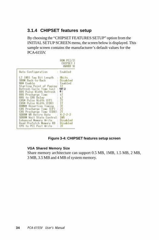
3.1.4 CHIPSET features setup
By choosing the “CHIPSET FEATURES SETUP” option from theINITIAL SETUP SCREEN menu, the screen below is displayed. Thissample screen contains the manufacturer’s default values for thePCA-6155V.
Figure 3-4: CHIPSET features setup screen
VGA Shared Memory SizeShare memory architecture can support 0.5 MB, 1MB, 1.5 MB, 2 MB,3 MB, 3.5 MB and 4 MB of system memory.

Chapter 3 Award BIOS Setup 35
3.1.5 Power management setup
The power management setup controls the CPU card's “green”features. The following screen shows the manufacturer’s default.
Figure 3-5: Power management setup screen
Power ManagementThis option allows you to determine if the values in power manage-ment are disabled, user-defined, or predefined.
HDD Power ManagementYou can choose to turn the HDD off after a one of the time intervallisted, or when the system is in Suspend mode. If in a power savingmode, any access to the HDD will wake it up.
Note: HDD will not power down if the Power Managementoption is disabled.
IRQ ActivityIRQ can be set independently. Activity on any enabled IRQ will wakeup the system.

36 PCA-6155V User's Manual
3.1.6 PCI configuration setup
Figure 3-6: PCI configuration screen
3.1.7 Load BIOS defaults
“LOAD BIOS DEFAULTS” indicates the most appropriate values forthe system parameters for minimum performance. These defaultvalues are loaded automatically if the stored record created by theSetup program becomes corrupted (and therefore unusable).
3.1.8 Load setup defaults
“LOAD SETUP DEFAULTS” loads the values required by the systemfor maximum performance.

Chapter 3 Award BIOS Setup 37
3.1.9 Integrated Peripherals
Figure 3-7: Integrated peripherals
Note: If you enable the IDE HDD block mode, the en-hanced IDE driver will be enabled.
3.1.10 Password setting
To change, confirm, or disable the password, choose the “PASS-WORD SETTING” option from the Setup main menu and press [Enter].The password can be at most 8 characters long.
Remember, to enable this feature. You must first select the SecurityOption in the BIOS FEATURES SETUP to be either “Setup” or“System.” Pressing [Enter] again without typing any characters candisable the password setting function.
3.1.11 IDE HDD auto detection
“IDE HDD AUTO DETECTION” automatically self-detect for thecorrect hard disk type.

38 PCA-6155V User's Manual
3.1.12 Save & exit setup
If you select this and press the [ENTER] key, the values entered in thesetup utilities will be recorded in the CMOS memory of the chipset.The microprocessor will check this every time you turn your systemon and compare this to what it finds as it checks the system. Thisrecord is required for the system to operate.
3.1.13 Exit without saving
Selecting this option and pressing the [ENTER] key lets you exit theSetup program without recording any new values or changing oldones.

CH
AP
TE
R
PCI SVGA Setup
The PCA-6155V features an on-boardVGA interface. This chapter providesinstructions for installing and operatingthe software drivers on the includeddisplay driver diskette.
4

40 PCA-6155V User's Manual
4.1 IntroductionThe PCA-6155V’s on-board VGA interface supports traditional analogCRT monitors. The VGA controller is built into the system's chip(SIS5598). It can support 1 to 4 MB of video memory share with thesystem memory. The interface can drive CRT displays with resolutionsup to 1024 x 768 in 256 colors at 1 MB share memory, and up to 1280x 1024 in 64 K colors at 4 MB share memory. The VGA interface isconfigured completely via the software utility, so you do not have toset any jumpers.
4.2 Before You BeginTo facilitate the installation of the enhanced display device drivers andutility software, you should read the instructions in this chaptercarefully before you attempt installation. The enhanced display driversfor the PCA-6155V board are located on the software installationdiskette. You must install the drivers and utility software by using thesupplied SETUP program for DOS drivers.
Note: The files on the software installation diskette arecompressed. Do not attempt to install the drivers bycopying the files manually. You must use thesupplied SETUP program to install the drivers.
Before you begin, it is important to note that most display drivers needto have the relevant software application already installed in thesystem prior to installing the enhanced display drivers. In addition,many of the installation procedures assume that you are familiar withboth the relevant software applications and operating system com-mands. Review the relevant operating system commands and thepertinent sections of your application software's user's manual beforeperforming the installation.

Chapter 4 PCI SVGA Setup 41
4.3 Utility DiskThe PCA-6155V is supplied with software utility disks that hold thenecessary files for setting up the VGA display and Ethernet andWindows controller. The disks are labeled as follows:
Disk 1: VGA utility for Windows NT
Disk 2: VGA utility for Windows 3.1 English version
Disk 3: VGA utility for OS2 3.0 #1
Disk 4: VGA utility for OS2 3.0 #2
Disk 5: IDE driver
Disk 6: VGA utility for Windows 95
Disk 7: VGA utility for Windows 3.1 Chinese version
Total: 7 disks
4.4 Driver Installation
Necessary prerequisitesThe instructions in this manual assume that you understand elementaryconcepts of MS-DOS and the IBM Personal Computer. Before youattempt to install any driver or utility you should: know how to copyfiles from a floppy disk to a directory on the hard disk, understand theMS-DOS directory structure, and know how to format a floppy disk. Ifyou are uncertain about any of these concepts, please refer to the DOSor Windows user reference guides for more information before youproceed with the installation.
Before you beginBefore you begin installing software drivers, you should make abackup copy of the display driver diskette and store the original in asafe place. The display driver diskette contains drivers for severalversions of certain applications. You must install the correct version inorder for the driver to work properly so make sure you know whichversion of the application you have.

42 PCA-6155V User's Manual
4.4.1 Windows setup
These drivers are designed to work with Microsoft Windows 3.1. Youmay install these drivers through Windows or in DOS.
Step 1: Install Windows as you normally would for a VGA display.Run Windows to make sure that it is working correctly.
Step 2: Place the display driver diskette in drive A. In WindowsProgram Manager, choose File from the Options Menu. Then from thepull-down menu, choose Run . . . . At the command line prompt, typeA:\setup. Press the <ENTER> key or click OK to begin the installa-tion. At this point the setup program locates the directory whereWindows is installed. For proper operation, the drivers must beinstalled in the Windows subdirectory. Press <ENTER> to completethe installation. Once completed, the Display Driver Control Panelappears on the screen. This Control Panel allows you to select andload the installed drivers.
Another method of installing these drivers is through the File Manager.Click on Drive A:. Then double-click on SETUP.EXE to begininstallation.
Changing Display Drivers in WindowsTo change display drivers in Windows, select the Windows Setup iconfrom the Main window. You will be shown the current setup configura-tion. Select Change System Settings from the Option menu. Click onthe arrow at the end of the Display line. You will be shown a list ofdisplay drivers. Click on the driver you want. Then click on the OKbutton. Follow the directions to complete the setup.
Changing Color SchemesAfter you change display drivers, you may notice that the color schemeused by Windows looks strange. This is because different drivers havedifferent default colors. To change the color scheme, select theControl Panel from the Main window. Select the Color icon. You willbe shown the current color scheme. Choose a new color scheme andclick the OK button.

Chapter 4 PCI SVGA Setup 43
4.4.2 DOS setup
Step 1: Install Windows as you normally would for a VGA display.Run Windows to make sure that it is working correctly. Then exitWindows.
Step 2: Place the display driver diskette in drive A. Type A: <EN-TER> to make this the default drive. Type SETUP <ENTER> to runthe driver SETUP program. Press any key to get to the applicationslist. Using the arrow keys, select Windows Version 3.1 and press the<ENTER> key. Press the <ENTER> key to select All Resolutions, andthen press <END> to begin the installation. At this point you will beasked for the path to your Windows System directory (defaultC:\WINDOWS). When the installation is complete, press any key tocontinue. Press <ESC> followed by Y to exit to DOS.
Step 3: Change to the directory where you installed Windows (usuallyC:\WINDOWS).
Step 4: Type SETUP <ENTER> to run the Windows Setup program.It will show the current Windows configuration. Use the up arrow keyto move to the Display line and press <ENTER>. A list of displaydrivers will be shown. Use the arrow keys to select one of the driversstarting with an asterisk (*) and press <ENTER>.
Step 5: Follow the directions on the screen to complete the setup. Inmost cases, you may press <ENTER> to accept the suggested option.When Setup is done, it will return to DOS. Type WIN <ENTER> tostart Windows with the new display driver.
Changing Display Drivers in DOSTo change display drivers from DOS, change to the Windows directoryand run Setup, repeating steps 4 and 5 from the previous page. Besidesthe special display drivers marked by an asterisk (*), you should beable to use the following standard drivers:
VGA 640x480, 16 colors
Super VGA 800x600, 16 colors

44 PCA-6155V User's Manual
Panning DriversSpecial panning drivers are provided to allow high-resolution modes tobe displayed on a flat panel or CRT. These drivers will show a sectionof a larger screen and will automatically pan, or scroll, the screenhorizontally and vertically when the mouse reaches the edge of thedisplay.
Linear Acceleration DriversA special high-performance linear acceleration driver is provided for256-color modes. This driver may require special hardware and maynot be supported on all systems. It is only available for Windows 3.1.
4.5 Windows 95 Drivers Setup Procedure1. Boot system with VGA or SuperVGA driver.
2. Select properties from a menu after right button press.
3. Select Display.
4. Select Change Display.
5. Select Change Monitor.
6. Select Change Adapter.
7. Select Have Disk.

Chapter 4 PCI SVGA Setup 45
4.6 Windows NT Drivers Setup Procedure
Step 1
1. Install Windows NT as you normally would for a VGA display.
2. First click the Start button, choose Settings and click on theControl Panel.
3. Choose the Display icon and click on the icon.
4. In the Display Properties window, click on the Settings tab.
5. Click on Change Display Type. In the Change Display Typewindow, click on the Change button under Adapter Type. This willbring up the Select Device window.
Step 2
1. In the Select Device window, click on the Other button. Entersource directory where the Windows NT driver files are located.
2. Press <ENTER> and the name of the Chips and TechnologiesVideo Accelerator driver will appear at the end of Models list box.Scroll to the end of the list box and double click on the driver.
3. Once the installation is complete, the system must be shut downand restarted.
Step 3
1. Upon restarting your computer, select the desired display settingsfrom the Display Property dialog box.
2. Click on Test to test the newly selected graphics mode. A color testscreen should appear, followed by the Testing Mode window.
3. Click on Yes to continue. The Display Settings Change windowwill appear.
4. Click on Restart Now for the new settings to take effect.

46 PCA-6155V User's Manual
4.7 OS/2 Drivers Setup Procedure
Preliminary steps
The following steps must be performed before you install the SIS5598display driver:
1. OS/2 DOS Support must be installed.
2. If you previously installed SVGA support, you must reset thesystem to VGA mode. VGA is the default video mode enabledwhen OS/2 is installed.
To restoreVGA mode, use Selective Install and select VGA forPrimary Display. For more information on this procedure, see thesection on Changing Display Adapter Support in the OS/2 User'sGuide.
Installing from diskette
To install this driver:
1. Open an OS/2 full screen or windowed session.
2. Place the SIS5598 Display Driver diskette in Drive A.
3. At the OS/2 command prompt, type the following commands tocopy the files to the OS/2 drive:
A: <ENTER> to make this the default drive.
SETUP A: C: <ENTER>
where A: is the floppy disk drive, and
C: is the hard disk partition containing \OS2
When the setup program is completed, you will need to perform ashutdown and then restart the system in order for changes to takeeffect.
A log of the information output during the install can be found in<root>:\OS2\INSTALL\DISPLAY.LOG

Chapter 4 PCI SVGA Setup 47
4. After restarting the system:
a) Open the OS/2 System folder.
b) Open the System Setup folder.
c) Open the Display Driver Install Object.
Steps a), b) and c) will execute the Display Driver Installation(DSPINSTL) utility program to finish installation of the newdrivers.
d) When the Display Driver Install window appears, selectPrimary Display and then select OK.
e) When the installation is complete, you will need to shut downand then restart the system for the changes to take effect. Makesure you remove the install diskette before restarting thesystem.
When the system has restarted, the display driver will be initialized for640 x 480 x 256 color, 60 Hz refresh. To switch to a different videoresolution color depth or a different refresh rate, see the followingsections:

48 PCA-6155V User's Manual
Selecting monitor type
Monitor type is initially set to DEFAULT. This DEFAULT setting maynot allow you to select all resolution/refresh combinations that areavailable for your monitor. The following steps can be done to selectmonitor type. This section applies only after installation, or when adifferent monitor is used.
1. Open the OS/2 System folder.
2. Open the System Setup folder.
3. Open the System object.
4. When the System-Settings notebook appears, select the Screen tab.This will take you to page 2 of the settings.
5. On Screen page 2, select your monitor type from the Display Namelist. If your monitor is not listed, select DEFAULT.
It may be necessary to restart your system to have all refresh rateoptions available.
Selecting screen resolution / refresh rate
To switch t a different video resolution, color depth or refresh rate:
1. Open the OS/2 System folder.
2. Open the System Setup folder.
3. Open the System object.
4. From the selection windows provided, select a new screen resolu-tion and screen refresh rate.
Note that refresh rates other than 60 Hz are only valid when thedisplay is switched to CRT Only display mode.
5. Close the System-Settings notebook.
6. Perform the shutdown and restart for the changes to take effect.

Chapter 4 PCI SVGA Setup 49
Installation notes
1. During the installation of this driver, DISPLAY.LOG andDSPINSTL.LOG files are created in the \OS2\INSTALL directory.These files identify the OS/2 system files that were updated, andindicate whether the installation was successful. theDISPLAY.LOG file also contains a string that identifies the versionof driver that was installed. This information may be importantwhen reporting an installation problem.
2. During installation, DSPINSTL will invoke the SVGAConfiguration program SVGA.EXE to determine the hardwareconfiguration, and create the file \OS2\INSTALL\SVGADATA.PMI.If this file is not created, the adapter will not be supported. Whenthis step is done, the display will be blanked out. You may see aseries of flashes on the display and/or what appears to be a"corrupted" display. This is normal, as the configuration process isperforming Video BIOS mode sets to determine which screenresolutions BIOS supports. This configuration information is thenused to provide the Systems-Settings Resolution and Refreshselections.

50 PCA-6155V User's Manual

Programming theWatchdog Timer
The PCA-6155V is equipped with awatchdog timer that resets the CPU orgenerates an interrupt if processing comesto a standstill for any reason. This featureensures system reliability in industrialstandalone or unmannedenvironments.
AP
PE
ND
IX
A

52 PCA-6155V User's Manual
Programming the Watchdog TimerTo program the watchdog timer, you must write a program whichwrites I/O port address 443 (hex). The output data is a value of timeinterval. The value range is from 01 (hex) to 3E (hex), and the relatedtime interval is 1 sec. to 62 sec.
Data Time Interval
01 1 sec.
02 2 sec.
03 3 sec.
04 4 sec.
• •
• •
• •
3E 62 sec.

Appendix A Programming the Watchdog Timer 53
After data entry, your program must refresh the watchdog timer byrewriting the I/O port 443 (hex) while simultaneously setting it. Whenyou want to disable the watchdog timer, your program should read I/Oport 443 (hex).
The following example shows how you might program the watchdogtimer in BASIC:
10 REM Watchdog timer example program20 OUT &H443, data REM Start and restart the watchdog30 GOSUB 1000 REM Your application task #1,40 OUT &H443, data REM Reset the timer50 GOSUB 2000 REM Your application task #2,60 OUT &H443, data REM Reset the timer70 X=INP (&H443) REM, Disable the watchdog timer80 END
1000 REM Subroutine #1, your application task• •• •• •1070 RETURN2000 REM Subroutine #2, your application task• •• •• •2090 RETURN

54 PCA-6155V User's Manual

Installing PC/104Modules
This appendix gives instructions forinstalling PC/104 modules.
AP
PE
ND
IX
B

56 PCA-6155V User's Manual
B.1 Installing PC/104 modulesThe PCA-6155V's PC/104 connectors give you the flexibility to attachPC/104 modules.
Installing these modules on the PCA-6155V is quick and simple. Thefollowing steps show how to mount the PC/104 modules:
1. Remove the PCA-6155V from your system paying particularattention to the safety instructions already mentioned above.
2. Make any jumper or link changes required to the CPU card now.Once the PC/104 module is mounted you may have difficulty inaccessing these.
3. Normal PC/104 modules have male connectors and mount directlyonto the main card. (Refer to the diagram on the following page.)
4. Mount the PC/104 module onto the CPU card by pressing themodule firmly but carefully onto the mounting connectors.
5. Secure the PC/104 module onto the CPU card using the fourmounting spacers and screws.

Appendix B Installing PC/104 Modules 57
Figure B-1: PC/104 module mounting diagram
Figure B-2: PC/104 module dimensions
PC/104Mount ing Support
8.9
95.990.8
5.1
0
05.1
90.285.1
82.5
3.2
6.4
φ
φ
Unit: mm (±0.1)

58 PCA-6155V User's Manual
Table B-1: PCA-6155V PC/104 connectors (CN14)
Pin Signal SignalNumber Row A Row B Row C Row D
1 IOCHCHK* 0 V SBHE* MEMCS16*2 SD7 RESETDRV LA23 IOCS16*3 SD6 +5 V LA22 IRQ104 SD5 IRQ9 LA21 IRQ115 SD4 -5 V LA20 IRQ126 SD3 DRQ2 LA19 IRQ157 SD2 -12 V LA18 IRQ148 SD1 ENDXFR* LA17 DACK0*9 SD0 +12 V MEMR* DRQ010 IOCHRDY N/C MEMW* DACK5*11 AEN SMEMW* SD8 DRQ512 SA19 SMEMR* SD9 DACK6*13 SA18 IOW* SD10 DRQ614 SA17 IOR* SD11 DACK7*15 SA16 DACK3* SD12 DRQ716 SA15 DRQ3 SD13 +5 V17 SA14 DACK1* SD14 MASTER*18 SA13 DRQ1 SD15 0 V19 SA12 REFRESH* KEY 0 V20 SA11 SYSCLK — —21 SA10 IRQ7 — —22 SA9 IRQ6 — —23 SA8 IRQ5 — —24 SA7 IRQ4 — —25 SA6 IRQ3 — —26 SA5 DACK2* — —27 SA4 TC — —28 SA3 BALE — —29 SA2 +5 V — —30 SA1 OSC — —31 SA0 0 V — —32 0 V 0 V — —
*active low

Pin Assignments
This appendix contains information of adetailed or specialized nature. It includes:
• CRT display connector
• RS-232/422/485 serial port connector
• Keyboard and mouse connector
• External keyboard connector
• IDE connector
• USB connector
• CPU fan power connector
• Floppy connector
• Parallel connector
• IR connector
• HDD LED connector
AP
PE
ND
IX
C

60 PCA-6155V User's Manual
C.1 CRT Display Connector (CN7)
Table C-1: PCA-6155V CRT display connector
Pin Signal Pin Signal1 RED 9 N/C2 GREEN 10 GND3 BLUE 11 DDCDAT4 N/C 12 N/C5 GND 13 H-SYNC6 GND 14 V-SYNC7 GND 15 DDCCLK8 GND
C.2 COM2 RS-232/422/485 Serial Port (CN9,CN11)
Table C-2: PCA-6155V COM2 RS-232/422/485 series port
CN11 CN9 CN9Pin RS-232 port RS-422 port RS-485 port1 DCD TXD- DATA-2 DSR N/C N/C3 RxD TXD+ DATA+4 RTS N/C N/C5 TxD RXD+ N/C6 CTS N/C N/C7 DTR RXD- N/C8 RI N/C N/C9 GND GND GND10 N/C N/C N/C
1
9
2
10

Appendix C Pin Assignments 61
C.3 External Keyboard Connector (CN10)
Table C-3: PCA-6155V external keyboard connector
Pin Signal1 CLK2 DATA3 NC4 GND5 VCC
C.4 COM1 RS-232 Serial Port (CN13)
Table C-4: PCA-6155V COM1 RS-232 serial port
Pin Signal1 DCD2 RXD3 TXD4 DTR5 GND6 DSR7 RTS8 CTS9 RI
15
96
54321
9876

62 PCA-6155V User's Manual
C.5 Keyboard and Mouse Connnector (CN16)
Table C-5: PCA-6155V keyboard and mouse connector
Pin Signal
1 KB DATA2 MS DATA3 GND4 VCC
5 KB CLOCK6 MS CLOCK

Appendix C Pin Assignments 63
C.6 IDE Hard Drive Connector (CON1, CON2)
Table C-6: PCA-6155V IDE hard drive connector
Pin Signal Pin Signal1 IDE RESET* 2 GND3 DATA 7 4 DATA 85 DATA 6 6 DATA 97 DATA 5 8 DATA 109 DATA 4 10 DATA 1111 DATA 3 12 DATA 1213 DATA 2 14 DATA 1315 DATA 1 16 DATA 1417 DATA 0 18 DATA 1519 SIGNAL GND 20 N/C21 IDE DRQA/B 22 GND23 IO WRITE 24 GND25 IO READ 26 GND27 IO CHANNEL READY 28 N/C29 HDACKO* 30 GND31 IRQ14 / IRQ15* 32 IOCS1633 ADDR 1 34 N/C35 ADDR 0 36 ADDR 237 HARD DISK SELECT 0* 38 HARD DISK SELECT 1*39 IDE ACTIVE* 40 GND
* Low active
39 37 .... 3 1
40 38 .... 4 2

64 PCA-6155V User's Manual
1
2
3
C.7 USB Connector (CN6)
Table C-7: USB1/USB2 connector
USB1 USB2Pin Signal Pin Signal1 +5 V 2 +5 V3 UV- 4 UV-5 UV+ 6 UV+7 GND 8 GND9 Chassis GND 10 N/C
C.8 CPU Fan Power Connector (CN15)
Table C-8: PCA-6155V CPU fan power connector
Pin Signal1 NC2 GND3 +12 V
1
9
2
10
Appendix C Pin Assignments 65
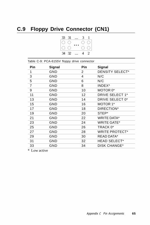
C.9 Floppy Drive Connector (CN1)
Table C-9: PCA-6155V floppy drive connector
Pin Signal Pin Signal1 GND 2 DENSITY SELECT*3 GND 4 N/C5 GND 6 N/C7 GND 8 INDEX*9 GND 10 MOTOR 0*11 GND 12 DRIVE SELECT 1*13 GND 14 DRIVE SELECT 0*15 GND 16 MOTOR 1*17 GND 18 DIRECTION*19 GND 20 STEP*21 GND 22 WRITE DATA*23 GND 24 WRITE GATE*25 GND 26 TRACK 0*27 GND 28 WRITE PROTECT*29 GND 30 READ DATA*31 GND 32 HEAD SELECT*33 GND 34 DISK CHANGE*
* Low active
1
2
33 31 .... 3
34 32 .... 4

66 PCA-6155V User's Manual
C.10 Parallel Port Connector (CN2)
Table C-10: PCA-6155V parallel port connector
Pin Signal1 \STROBE2 \AUTOFD3 D04 ERR5 D16 \INIT7 D28 \SLCTINI9 D310 GND11 D412 GND13 D514 GND15 D616 GND17 D718 GND19 \ACK20 GND21 BUSY22 GND23 PE24 GND25 SLCT26 N/C
1
226 24
25 23
....
3....
4

Appendix C Pin Assignments 67
C.11 IR Connector (CN5)
Table C-11: PCA-6155V IR connector
Pin Signal1 +5 V2 N/C3 IR_RX4 GND5 IR_TX
C.12 HDD LED Connector (JP1)
Table C-12: PCA-6155V HDD LED connector
Pin Signal1 VCC
2 LED

68 PCA-6155V User's Manual
C.13 System I/O Ports
Table C-13: System I/O ports
Addr. range (Hex) Device000-01F DMA controller020-021 Interrupt controller 1, master022-023 Chipset address040-05F 8254 timer060-06F 8042 (keyboard controller)070-07F Real-time clock, non-maskable interrupt (NMI)
mask080-09F DMA page register,0A0-0BF Interrupt controller 20C0-0DF DMA controller0F0 Clear math co-processor0F1 Reset math co-processor0F8-0FF Math co-processor1F0-1F8 Fixed disk200-207 Game I/O278-27F Parallel printer port 2 (LPT 3)2F8-2FF Serial port 2300-31F Prototype card360-36F Reserved378-37F Parallel printer port 1 (LPT 2)380-38F SDLC, bisynchronous 23A0-3AF Bisynchronous 13B0-3BF Monochrome display and printer adapter(LPT1)3C0-3CF Reserved3D0-3DF Color/graphics monitor adapter3F0-3F7 Diskette controller3F8-3FF Serial port 1* PNP audio I/O map range from 220 ~ 250H (16 bytes) MPU-401 select from 300 ~ 330H (2 bytes)

Appendix C Pin Assignments 69
C.14 DMA Channel Assignments
Table C-14: DMA channel assignments
Channel Function0 Available1 Available2 Floppy disk (8-bit transfer)3 Available4 Cascade for DMA controller 15 Available6 Available7 Available* Audio DMA select 0, 1 or 3

70 PCA-6155V User's Manual
C.15 Interrupt Assignments
Table C-15: Interrupt assignments
Interrupt# Interrupt sourceIRQ 0 Interval timerIRQ 1 KeyboardIRQ 2 Interrupt from controller 2 (cascade)IRQ 3 Serial communication port 2IRQ 4 Serial communication port 1IRQ 5 Parallel port 2IRQ 6 Diskette controller (FDC)IRQ 7 Parallel port 1 (print port)IRQ 8 Real-time clockIRQ 9 Cascaded to INT 0A (IRQ 2)IRQ 10 AvailableIRQ 11 WatchdogIRQ 12 PS/2 mouseIRQ 13 INT from co-processorIRQ 14 Primary fixed diskIRQ 15 Secondary fixed disk* PNP audio IRQ select: 5, 7, 9, 10, 11 or 12
C.16 1st MB Memory Map
Table C-16: 1st MB memory map
Addr. range (Hex) DeviceF000h - FFFFh System ROMC800h - EFFFh UnusedC000h - C7FFh Expansion ROMB800h - BFFFh CGA/EGA/VGA textB000h - B7FFh UnusedA000h - AFFFh EGA/VGA graphics0000h - 9FFFh Base memory

DOC® 2000Installation Guide
This appendix contains information onthe DiskOnChip® 2000 quick installationguide. It includes:
• DiskOnChip® 2000 installationinstructions
• Additional information and assistanceA
PP
EN
DIX
D

72 PCA-6155V User's Manual
DiskOnChip ® 2000 Quick Installation Guide
DiskOnChip ® 2000 installation instructions
1. Make sure the target platform is powered OFF.
2. Plug the DiskOnChip® 2000 device into its socket. Verify thedirection is correct (pin 1 of the DiskOnChip® 2000 is aligned withpin 1 of the socket).
3. Power up the system.
4. During power up you may observe the messages displayed by theDiskOnChip® 2000 when its drivers are automatically loaded intothe system's memory.
5. At this stage the DiskOnChip® 2000 can be accessed as any disk inthe system.
6. If the DiskOnChip® 2000 is the only disk in the system, it willappear as the first disk (drive C: in DOS).
7. If there are more disks besides the DiskOnChip 2000, theDiskOnChip® 2000 will appear by default as the last drive, unless itwas programmed as the first drive. (Please refer to theDiskOnChip® 2000 utilities user manual.)
8. If you want the DiskOnChip® 2000 to be bootable:
a . Copy the operating system files into the DiskOnChip® by usingthe standard DOS command (for example: sys d:).
b . The DiskOnChip® should be the only disk in the systems orwould be configured as the first disk in the system (c:) usingthe DUPDATE utility.
DUPDATE D /S: DOC104.EXB /FIRST (set as c:)DUPDATE C /S: DOC104.EXB (set as d:)

Appendix D DOC® 2000 Installation Guide 73
Additional information and assistance
1. Visit M-Systems' Web site at www.m-sys.com where you canfind Utilities Manual, Data Sheet and Application Notes. Inaddition, you can find the latest DiskOnChip® 2000 S/WUtilities.
2. Contact your dealer for technical support if you need additionalassistance, and have the following information ready:
• Product name and serial number
• Description of your computer hardware (manufacturer,model, attached devices, etc.)
• Description of your software (operating system, version,application software, etc.)
• A complete description of the problem
• The exact wording of any error messages

74 PCA-6155V User's Manual