pc11 spectral power converter - infratek-ag.com pc11 high precision power converter is the ... and...
TRANSCRIPT

PC11 Spectral Power Converter
The Swiss way of measuring power

_______________________________________ page 2 ________________________________
The PC11 High Precision Power Converter is the state-of-the-art instrument and an ideal tool for many measurement applications and offers engineers and technicians innumberable opportunities.
Precision Power Converter with Computer Operation Basic Accuracy V, A, W: 0.02%, 0.02%, 0.04% Bandwidth: DC to 2MHz V-, A- Measurement: 0.3V - 1000V, 50μA - 40A Hi Current Sensors: 10A - 700A, 0.005% Measurement Resolution: 18Bit Individual Settings: every phase, all phases 4 Measure Modes: Standard, Logging, Transient, Power-Speed
Upgrading the instrument is feasible due to modular concept at any time.
Reliable, simple and intuitive to use; highly accurate measurements for test and
development of modern, efficient power electronics.
_______________________________________ page 3 ________________________________
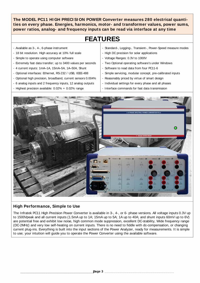
The MODEL PC11 HIGH PRECISION POWER Converter measures 280 electrical quanti-ties on every phase. Energies, harmonics, motor- and transformer values, power sums, power ratios, analog- and frequency inputs can be read via interface at any time
FEATURES - Available as 3-, 4-, 6-phase instrument - 18 bit resolution. High accuracy at 10% full scale - Simple to operate using computer software - Extremely fast data transfer; up to 3400 values per seconds - 4 current inputs: 1mA–1A, 15mA–5A, 1A–50A, Shunt - Optional interfaces: Ethernet, RS-232 / USB, IEEE-488 - Optional high precision, broadband, current sensors 0.004% - 6 analog inputs and 2 frequency inputs, 12 analog outputs - Highest precision available: 0.02% + 0.02% range
- Standard-, Logging-, Transient-, Power-Speed measure modes - High DC precision for solar applications - Voltage Ranges: 0.3V to 1000V - Two Optional operating software’s under Windows - Software to read data from four PC11-6 - Simple servicing, modular concept, pre-calibrated inputs - Reasonably priced by virtue of smart design - Individual settings for every phase and all phases - Interface commands for fast data transmission
High Performance, Simple to Use The Infratek PC11 High Precision Power Converter is available in 3-, 4-, or 6- phase versions. All voltage inputs 0.3V up to 1500Vpeak and all current inputs (1.5mA up to 1A; 15mA up to 5A; 1A up to 40A; and shunt inputs 60mV up to 6V) are potential free and exhibit low noise, high common mode suppression, excellent DC-stability, Wide frequency range (DC-2MHz) and very low self-heating on current inputs. There is no need to fiddle with dc-compensation, or changing current plug-ins. Everything is built into the input sections of the Power Analyzer, ready for measurements. It is simple to use; your intuition will guide you to operate the Power Converter using the available software.

_______________________________________ page 4 ________________________________
MEASUREMENT FUNCTIONS Four different measure functions enhance the PC11 Power Converter capabilities. Standard Measure Mode: In the Standard Measure Mode 280 quantities per phase are measured without gap and are continuously updated using the computer software. Two electric motors can be tested simultaneously. External Speed and torque inputs are optionally available. Transformer values are imple-mented too.
Logging Measure Mode: This measure mode is suitable for very fast measurements or for long time averaging of data. It is possible obtaining 6 datasets of a 6-phase instrument within 20ms or 6 datasets per 10 minutes. From every phase you obtain 8 values: frequency, rms current, rms voltage, power, power factor, apparent power, energy Wh, and appar-ent energy VAh. Cycles: For Logging Measure Mode set Cycles 1 to 32000. Defines the measurement duration per measurement set. Format 160.
Transient Measure Mode: You can catch current-, voltage-, and power wave forms in a start-up on transient mode up to 6 phases simultaneously or you can view all the wave forms at a critical operating point. Sections of the wave forms can be expanded by simply using the Zoom A, B, C and D buttons of the program. Transient ID: Set it to 1, 2, 3, 4, 5, 6, or 7. The transient ID deter-mines the measurement duration after start. Transient ID Measure-ment duration: 1 {0.25s} 2 {0.5s} default, 3 {1s}, 4 {2s}, 5 {4s}, 6 {8s}, 7 {16s}.
Power-Speed Measure Mode: This measure mode analyzes the performance of devices such as elec-tric cars. In 20ms intervals the following data are transferred: rms current, rms voltage, power, apparent power, energy, apparent energy, and rpm of a shaft. At the end of the measurement, (maximum 11 seconds) data versus time are displayed, can be expanded to view details.

_______________________________________ page 5 ________________________________
APPLICATIONS
Electric Motors (Railroad systems) The PC11-6 equipped with (Option03) 6 analog inputs, 2 digital inputs and 12 outputs per-form all required measurements for motor testing. The analog inputs can be used for torque-, temperature and vibration measurements. The TTL inputs for speed or torque, and the external synchronization input per phase from an encoder to synchronize to the pole position. The PC11-6 can measure 2 motors simultaneously: input power, output power, torque, slip, speed, and efficiency of every motor, as well as all harmonics of current, voltage, power, impedance, and phase angle. For none sinusoidal signals (trapezoidal wave-forms or frequency inverters), we recommend to use the fundamental of impedance and funda-mental of phase. From these values the motor inductances L, Ld, Lq and the motor re-sistances R = Rm + Rdc can be determined. The motor DC-resistance is obtained by applying a DC-current: Rdc = Pdc / I2dc. Rm is a magnetization dependent loss. Simultaneous Measurement of 2 Synchronous Motors (PMSM, BLDC) A wide range of synchronous motors are on the market (PMSM, IPMSM, BLDC). The power consumption ranges from mW to 500kW. Many different constructions are in use. They all have in common that the magnetic field rotation (2 phase or 3 phase) is electronically generated. A wide range of speeds (rpm) are available. See also the Infratek documentation: Electric Motor Testing (PDF). Inverter drive systems Using the PC11-6 to test the efficiency of an inverter drive, simultaneous measurement of all electrical parameters is essential. By visually inspecting the current waveform, we should see three individual currents all producing an alternating positive/negative pattern waveform. All three phases should be symmetrical. The PC11-6 measures very precisely total input power, total output power and inverter efficiency! Automotive Testing fuel pumps is crucial for proper and reliable vehicle operation and long lasting product quality. Individual fuel pump tests like Start-Stop, Low-Speed/Full-Speed are used; the PC11 delivers all important electrical parameters. The PC11 in the power-speed meas-ure mode measures the start performance of an electric car. In 20ms intervals current, voltage, power, energy, and speed of the vehicle are measured. Data are plotted versus speed.
Solar/Wind energy Decisive for an effective technical implementation of solar plants and wind farms are vari-ous simulations and correlations for each location. In these tests, exactly defined levels are simulated. All relevant electrical parameters like frequency, voltage, current, power, effi-ciency, power factor and energies are measured by the PC11 and can be read via com-puter software. A dedicated high speed data acquisition software is available to read data from several PC11. Data are combined in a sin-gle file for simple analysis.
Power electronics / Appliance Wide bandwidth guarantees precise power measurement of switching power supplies or other electronically switched devices. Some electronic devices consume power when they appear to be turned off. This power consumption is known as standby power and can be a significant contribution to product energy use. The PC11 Power Analyzer precisely measure standby power on all kind of ap-pliances like ovens, ceramic hobs, washers, dryers etc. This can be done using the 1.5mA/5mA/15mA current ranges. PC11 Computer Software for Production Testing For efficient production testing of 12 (or more) single phase apparatus, a dedicated high speed data acquisition software is available. It reads the data of 12 apparatus (or more) in less than 100ms and combines data in a single file for storage or analysis.
_______________________________________ page 6 ________________________________
Specifications
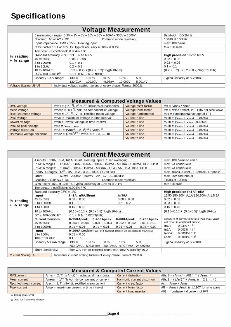
Voltage Measurement
% reading + % range
8 measuring ranges: 0.3V – 1V – 3V – 10V – 30V – 100V – 300V – 1000V Bandwidth DC-2MHz Coupling: AC or AC + DC Common mode rejection: 100dB at 100kHz Input impedance: 1M / 15pF. Floating input max. 1000Vrms Crest Factor 15:1 at 10% fs. Typical accuracy at 10% is 0.1% fs = full scale Temperature coefficient: 0.004% / C Standard accuracy 23C ±1C. 3V to 600V 45 to 65Hz 0.08 + 0.08 3 to 1000Hz 0.1 + 0.1 1 to 10kHz 0.2 + 0.2 10 to 100kHz (0.2 + 0.2) +(0.2 + 0.2)*log(f/10kHz) DC1)//100-500kHz1) 0.1 + 0.1// 0.012*f(kHz)
High precision 10V to 600V 0.02 + 0.02 0.03 + 0.03 0.1 + 0.1 (0.2 + 0.2) +(0.2 + 0.2)*log(f/10kHz)
Linearity 100V range: 130 % 100 % 50 % 10 % 5 % 130.01V 100.00V 49.988V 10.000V 5.0014V
Typical linearity at 50/60Hz
Voltage Scaling U1-U6 Individual voltage scaling factors of every phase. Format 2000.8.
Measured & Computed Voltage Values RMS voltage Vrms = (1/T T0 V2 dt)1/2, includes all harmonics Voltage crest factor Vcf = Vmax / Vrms Mean voltage Vmean = 1/T T0 Vdt, dc component of voltage Voltage form factor Vff = Vrms / Vrect, is 1.1107 for sine wave Rectified mean voltage Vrect = 1/T T0 IVI dt, rectified mean voltage Voltage fundamental V01 = fundamental voltage of FFT Peak voltage Vmax = maximum voltage in time interval V1 line to line V1 ltl = (V1rms + V2rms) 0.86603 Lowest voltage Vmin = lowest voltage in time interval V2 line to line V2 ltl = (V2rms + V3rms) 0.86603 Peak to peak voltage Vptp = Vmax – Vmin V3 line to line V3 ltl = (V3rms + V1rms) 0.86603 Voltage distortion Vthd1 = (Vrms2 – V012)1/2 / Vrms, 2) V4 line to line V4 ltl = (V4rms + V5rms) 0.86603 Harmonic voltage distortion Vthd2 = (Vn2)1/2 / Vrms, n = 2,3, …, 40 V5 line to line V5 ltl = (V5rms + V6rms) 0.86603 V6 line to line V6 ltl = (V6rms + V4rms) 0.86603
Current Measurement
% reading + % range
4 inputs: In30A, In5A, In1A, shunt. Floating inputs. 1 sec averaging. max. 1000Vrms to earth In1A: 6 ranges 1.5mA1) - 5mA - 15mA - 50mA - 150mA - 500mA - 1500mA. DC-100kHz max. 2A continuous In5A: 6 ranges: 15mA1) - 50mA - 150mA - 500mA - 1.5A - 5A - 15A. DC-100kHz max. 7A continuous In30A: 4 ranges: 1A1) - 3A - 10A - 30A - 100A. DC-100kHz max. 40A/30A cont., 1-3phase /4-6phase Shunt: 60mV - 200mV - 600mV - 2V - 6V. DC-100kHz max. 30V continuous Coupling: AC or AC + DC Common mode rejection: 115dB at 100kHz Crest factor 15:1 at 10% fs. Typical accuracy at 10% fs is 0.1% fs = full scale Temperature coefficient: 0.004% / oC Standard accuracy 23oC ± 1oC Input In1A,In5A,Shunt In30A 45 to 65Hz 0.08 + 0.08 0.08 + 0.08 3 to 1000Hz 0.1 + 0.1 0.2 + 0.2
High precision In1A/In5A 15,50,150,500mA,1A/150,500mA,1.5,5A 0.02 + 0.02 0.03 + 0.03
1 to 10kHz 0.15 + 0.15 0.15 + 0.15 10 to 100kHz (0.15+0.15)+ (0.5+0.5)*log(f/10kHz) (0.15+0.15)+ (0.5+0.5)*log(f/10kHz) DC1)//100-500kHz1) 0.1 + 0.1// 0.023*f(kHz) Current Sensors 0-150Apeak 0-400Apeak 0-600Apeak 0-700Apeak 45 to 65Hz 0.004 + 0.004 0.004 + 0.004 0.002 + 0.002 0.01 + 0.01 3 to 1000Hz 0.01 + 0.01 0.01 + 0.01 0.01 + 0.01 0.02 + 0.02
Exposure of current inputs to their max. value will result in additional errors1) In1A: 0.03% * I2 In5A: 0.003% * I2 In30A: 0.0001% * I2 Coax: 0.0001% * I2
Input 0-100A precision current sensor (Option 04) connected to In1A input 3 to 100Hz 0.05 + 0.05 100 to 1000Hz 0.1 + 0.1 Linearity 500mA range: 130 % 100 % 50 % 10 % 5 % 650.02mA 500.02mA 250.02mA 49.979mA 24.997mA
Typical linearity at 50/60Hz
Shunt Sensitivity: 60mV/A. For an external shunt with 1mV/A scale by 60.0 Current Scaling I1-I6 Individual current scaling factors of every phase. Format 2000.8.
Measured & Computed Current Values RMS current Arms = (1/T T0 A2 dt)1/2, includes all harmonics Current distortion Athd1 = (Arms2 – A012) 1/2 / Arms, 2) Mean current Amean = 1/T T0 Adt, dc-component of current Harmonic current distortion Athd2 = (An2)1/2 / Arms, n = 2,3, … 40 Rectified mean current Arect = 1/T T0 lAl dt, rectified mean current Current crest factor Acf = Amax / Arms Peak current Amax = maximum current in time interval Current form factor Aff = Arms / Arect, is 1.1107 for sine wave Current fundamental A01 = fundamental current of FFT 1) Typical max. Error
2) Used for frequency inverter

_______________________________________ page 7 ________________________________
Power Measurement
% reading +% range
W range = voltage range times current range 112 power ranges Standard accuracy 23oC ± 1oC Input PF In1A, In5A, Shunt 45 to 65Hz 0-1 0.16 + 0.16 45 to 65Hz 0-0.05 3 to 1000Hz 0-1 0.2 + 0.2
High precision In1A, In5A, Shunt 0.04 + 0.04 0.01 + 0.01 0.1 + 0.1
1 to 20kHz 0-1 0.2+(0.2 + 0.2*log (f/100Hz) + 0.08*k1*log (f/100Hz)) 20 to 100kHz 1 %error (A+V) %error (A+V) DC1)//100-500kHz1) 1 0.2 + 0.2// add %error (V+A) Input PF In30A Current Sensor 0-100A 45 to 65Hz 0-1 0.16 + 0.16 0.1 + 0.1
3 to 1000Hz 0-1 0.2+(0.2+0.2 * log(f/3Hz) + 0.1 *k1 * log(f/3Hz) DC1) 0.2 + 0.2 0.1 + 0.1 PF 1 0.9 0.8 0.7 0.6 0.5 0.4 0.3 0.2 0.1 0 k1 0.5 0.74 0.97 1.18 1.38 1.55 1.70 1.83 1.92 1.98 2.00
k1 = (2 –PF4) / (1+PF2) 1) Typical max. error
W Linearity 130% 100% 50% 10% 5% Volt 130.00 100.00 49.985 9.9992 4.9990 Ampere 6.5004 5.0014 2.5020 500.82m 250.40m Watt PF=1 844.74 500.07 125.05 5.0056 1.2522
Typical linearity of voltage, current and power
Measured & Computed Power Values
Active power W = 1/T T0 ui dt, total power in W Fundamental power W01 = A01 V01 cos 01, 01 = phase Apparent power VA = Arms Vrms, total apparent power VA Fundamental apparent power VA01 = A01 V01 Reactive power Var = (Papp2 – Pact2)1/2, reactive power Var Fundamental reactive power Var01 = (VA012 – W012)1/2, magnitude only Power Factor PF = Pact / Papp, includes all harmonics Power of distortion D = V01(An2)1/2, n = 2,3, …, 40; D in Watt Power Factor of Fundamental PF01 = W01 / VA01
Frequency Measurement SyncA: 2Hz-5kHz SyncV: 2Hz-150kHz S_ExtV: 2Hz-150kHz S_ExtV is a TTL output for SyncA/V or a TTL input for S_ExtV
Accuracy: 0.05 % Accuracy: 0.05 % Accuracy: 0.05 % Sync for each phase
Measured & Computed Values Frequency Freq =zero crossing of A, V, Ext; SYNC I, SYNC U, Ext; Accuracy 0.05%
Energy Measurement Wh, VAh, Varh, Ah, integration time. Add accuracy % of values involved. Reset sets all values to zero. Integration runs uninterrupted, also in the background.
Measured & Computed Values Energy Wh = t0 Pact dt, active energy in Wh Battery charge Ah = t0 Arect dt, is positive only Apparent energy VAh = t0 Papp dt, use it for long term PF Elapsed time time = t0 dt, time in hours since RESET Reactive energy VAR = t0 Prea dt, can be positive / negative Time Accuracy: 0.05 %
Harmonic Measurement Frequency range of fundamental 3Hz – 15kHz Harmonics: V and A: 1-88; W and phase angle 1-21 Accuracy: Fundamental1), use % figures of V, A, W
FFT averaging: Set FFT ID = 0, 1, 2, 3, 4 which corresponds to averaging over 4, 16, 64, 256, or 1024 periods.
The whole range of harmonics can be read via interface.
Measured & Computed Values Magnitude impedance Mag Z = V01 / A01 fundamental Phase of fundamental Phi01 = phase V01, A01
Additional Computed Values Accuracy: Add % figures of values involved 65 values per phase Rectified mean, VA, Var, impedance, distortion factor, power factors, motor- and transformer values, sums, ratios, analog inputs and -outputs, speed in-puts, and more are continuously updated and ready for interface output. 1) Typical max. Error

_______________________________________ page 8 ________________________________
Measured & Computed Values
Sum1 of power Sum1 = Pact1 + Pact2 + Pact3; Power phase 1+2+3 Ratio1 of power Ratio1 = Pact4 / Pact1 + Pact2 + Pact3 Sum2 of power Sum2 = Pact1 + Pact2 Ratio2 of power Ratio2 = Pact3 / Pact1 + Pact2 Sum3 of power Sum3 = Pact4 + Pact5 + Pact6; Power phase 4+5+6 Ratio3 of power Ratio3 = Pact2 / Pact1 Sum4 of power Sum4 = Pact4 + Pact5 Ratio4 of power Ratio4 = Pact4 + Pact5 + Pact6 / Pact1 +Pact2 +Pact3 Sum5 of power Sum5 = not used Ratio5 of power Ratio5 = Pact6 / Pact4 + Pact5 Sum6 of power Sum6 = not used Ratio6 of power Ratio6 = Pact5 / Pact4
Motor Measurement Measured & Computed Values from phase 1, phase 2, phase 3
Measured & Computed Values from phase 4, phase 5, phase 6
Mechanical input power Pin = electric power applied to motor Mechanical input power Pin = electric power applied to motor Mechanical output power Pout = Pin – Pin at no load in Watt (Loss) Mechanical output power Pout = Pin – Pin at no load in Watt Torque Torque = Pout poles1 / 4 frequency1 Torque Torque = Pout poles / 4 frequency2 Slip Slip = 1 – fout / fin Slip Slip = 1 – fout / fin Rotation per minute rpm = 120 frequency1 / poles1 Rotation per minute rpm = 120 frequency / poles Efficiency efficiency = 1 – Pin at no load / Pin Efficiency efficiency = 1 – Pin at no load / Pin
Transformer Measurement Measured & Computed Values from phase 1 and phase 2
Vrect, rms corrected Vcorrected = 1.1107 Vrect Loss resistance Equivalent loss resistance = Pact1 / Arms2 Corrected power Corr power = Pact 1 / (0.5 + 0.5 Vrms / Vcorrected) Loss inductance Equivalent loss reactance = Prea 1 / Arms2 Loss factor Q Q = tan X/R, where Z=R + jX Turn ratio Turn ratio = N2 / N1 = Vrms2 / Vrms1, no load
Analog Input / Output Analog Input Analog Output 4 Analog inputs (I1-I4) 2 analog inputs (I5-I6) 2 TTL auto ranging speed inputs 20Hz-150kHz
5V, 100k input impedance, accuracy 0.2%1) 10V, 100k input impedance, accuracy 0.2%1) Accuracy 0.1%1). Reading rate in Standard-Mode 0.5sec, reading rate in Power Speed-Mode 20ms Each input can be scaled 0.0001 up to 99999
12 analog outputs (O1-O12)
5V, 1k output impedance, accuracy 0.2%1) Update rate 0.5sec. Arms, Vrms, W, VA, Var, PF, Frequency, and Wh can be sent to the analog outputs. In Logging- and Power Speed-Mode output1 is an actuator to Start/Stop ext. devices.
Scaling An1-An6 Individual analog scaling. Format 10.0. Scaling rpm1-rpm2 TTL freq1/rpm1 and freq2/rpm2 scaling. Format 2.0. For 180 pulses per turn, scaling = 1.0000
Four Measuring Functions Standard 1 to 6 phase, measures all electrical values at 0.8s updates or 100ms updates. Logging Up to 48 values in 20ms, or long time averaging up to 10 minutes. Transient Simultaneous V-, A-, W-waves on 6 phases, time 0.25 to 16 seconds. Power-Speed Measures in 20ms intervals V, A, W, VA, Wh, VAh, speed of rotating devices. 1) Typical max. Error
Interface 10/100 Mbps Ethernet interface (Up to 230.4kBaud) RS232 Interface (Up to 115.2kBaud) or USB Interface (Up to 921.6kBaud) Analog Input / Output connector (37-pole) GPIB, IEEE 488.2 (Set address 1 to 30)
Servicing and Calibration Servicing: Replacement amplifier boards from the factory are calibrated (no re-calibration is required). All other boards can simply be exchanged. Calibration: Use computer software, follow calibration instructions. Apply 60Hz, 1.5mA - 20A, and 0.3V - 1000V. Calibration cycle 2 years.
_______________________________________ page 9 ________________________________
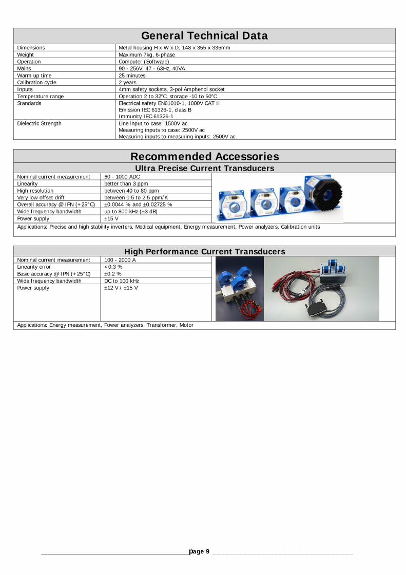
General Technical Data
Dimensions Metal housing H x W x D; 148 x 355 x 335mm Weight Maximum 7kg, 6-phase Operation Computer (Software) Mains 90 - 256V, 47 - 63Hz, 40VA Warm up time 25 minutes Calibration cycle 2 years Inputs 4mm safety sockets, 3-pol Amphenol socket Temperature range Operation 2 to 32oC, storage -10 to 50oC Standards Electrical safety EN61010-1, 1000V CAT II
Emission IEC 61326-1, class B Immunity IEC 61326-1
Dielectric Strength Line input to case: 1500V ac Measuring inputs to case: 2500V ac Measuring inputs to measuring inputs: 2500V ac
Recommended Accessories Ultra Precise Current Transducers
Nominal current measurement 60 - 1000 ADC
Linearity better than 3 ppm High resolution between 40 to 80 ppm Very low offset drift between 0.5 to 2.5 ppm/K Overall accuracy @ IPN (+25°C) 0.0044 % and 0.02725 % Wide frequency bandwidth up to 800 kHz (3 dB) Power supply 15 V Applications: Precise and high stability inverters, Medical equipment, Energy measurement, Power analyzers, Calibration units
High Performance Current Transducers Nominal current measurement 100 - 2000 A
Linearity error <0.3 % Basic accuracy @ IPN (+25°C) 0.2 % Wide frequency bandwidth DC to 100 kHz Power supply 12 V / 15 V
Applications: Energy measurement, Power analyzers, Transformer, Motor
______________________________________ page 10 ________________________________
Typical performance at low power factor.
UUT SYSTEM ERROR EXP.TEST RANGE INDICATED ACTUAL MODIFIER ERROR (%TOL) UNCERTCHANNEL 1: 1A INPUT
50W Range (10V/500mA):177 50 50.016W 50.0000W 50H_Cos=1 0.032% 40 3.3mW178 50 35.367W 35.3550W 50H_Cos=0.707 0.033% 34 3.2mW179 50 40.013W 40.0000W 50H_Cos=0.8 0.033% 37 3.2mW180 50 4.003W 4.0000W 50H_Cos=0.08 0.067% 12 1.7mW181 50 0.401W 0.4000W 50H_Cos=0.008 0.352% 28 1.7mW
150W Range (300V/500mA):182 150 115.0220W 150.0000W 50H_Cos=1 0.019% 21 8.4mW183 150 81.3404W 81.31700W 50H_Cos=0.707 0.029% 25 7.5mW184 150 92.0246W 92.00000W 50H_Cos=0.8 0.027% 25 6.1mW185 150 9.2065W 9.20000W 50H_Cos=0.08 0.070% 10 3.7mW186 150 0.9253W 0.92000W 50H_Cos=0.008 0.571% 35 3.7mW
CHANNEL 1: 5A INPUT150W Range (100V/1.5A):
189 150 150.052W 115.0000W 50H_Cos=1 0.035% 43 20mW190 150 106.098W 106.0660W 50H_Cos=0.707 0.030% 31 14mW191 150 120.030W 120.0000W 50H_Cos=0.8 0.025% 28 15mW192 150 12.000W 12.0000W 50H_Cos=0.08 -0.0000167% 0 2.3mW193 150 1.195W 1.2000W 50H_Cos=0.008 -0.380% 30 860uW
450W Range (230V/1.5A)194 450 345.078W 345.0000W 50H_Cos=1 0.023% 25 43mW195 450 243.996W 243.9520W 50H_Cos=0.707 0.018% 16 20mW196 450 276.062W 276.0000W 50H_Cos=0.8 0.022% 21 20mW197 450 27.607W 27.6000W 50H_Cos=0.08 0.027% 4 25mW198 450 2.752W 2.7600W 50H_Cos=0.008 -0.306% 19 13mW
CHANNEL 2: 1A INPUT50W Range (100V/500mA):
233 50 50.012W 50.0000W 50H_Cos=1 0.024% 31 3.8mW234 50 35.365W 35.3550W 50H_Cos=0.707 0.028% 29 3.0mW235 50 40.011W 40.0000W 50H_Cos=0.8 0.029% 32 3.4mW236 50 4.004W 4.0000W 50H_Cos=0.08 0.097% 18 1.8mW237 50 0.403W 0.4000W 50H_Cos=0.008 0.836% 66 1.8mW
150W Range (300V/500mA):238 150 115.0100W 115.00000W 50H_Cos=1 0.000087% 9 11mW239 150 81.3302W 81.31700W 50H_Cos=0.707 0.016% 14 7.2mW240 150 92.0192W 92.00000W 50H_Cos=0.8 0.021% 20 8.6mW241 150 9.2100W 9.20000W 50H_Cos=0.08 0.109% 16 3.8mW242 150 0.9272W 0.92000W 50H_Cos=0.008 0.778% 47 3.9mW
CHANNEL 2: 5A INPUT150W Range (100V/1.5A):
245 150 150.042W 150.0000W 50H_Cos=1 0.028% 35 18mW246 150 106.094W 106.0660W 50H_Cos=0.707 0.026% 27 15mW247 150 120.028W 120.0000W 50H_Cos=0.8 0.023% 26 16mW248 150 12.003W 12.0000W 50H_Cos=0.08 0.027% 5 2.1mW249 150 1.200W 1.2000W 50H_Cos=0.008 0.020% 2 2.3mW
450W Range (230V/1.5A)250 450 345.040W 345.0000W 50H_Cos=1 0.012% 13 43mW251 450 243.988W 243.9520W 50H_Cos=0.707 0.015% 13 17mW252 450 276.044W 276.0000W 50H_Cos=0.8 0.016% 15 21mW253 450 27.603W 27.6000W 50H_Cos=0.08 0.0000942% 1 12mW254 450 2.764W 2.7600W 50H_Cos=0.008 0.135% 8 17mW

______________________________________ page 11 ________________________________
Infratek AG has a broad and well-established network of distributors. Find your local partner on our website or contact us directly.
Infratek AG, Weingartenstrasse 6, 8707 Uetikon am See/Switzerland Telephone: +41 44 920 50 05 Fax: +41 44 920 60 34 Email: [email protected] Internet: www.infratek-ag.com