pbu propane floor burnisher - nilfisk...pbu propane floor burnisher 04/15 form no. 56043169 service...
TRANSCRIPT

PBU Propane Floor Burnisher
04/15 Form No. 56043169
Service ManualModel Numbers: 56384165 PBU 21KACAT56384166 PBU 27KACAT
56384167 PBU 21KACATCLDC56384168 PBU 27KACATCLDC
English
21 KACATBase Model
27 KACATBase Model
21 KACAT CLDCDust Control Model
27 KACAT CLDCDust Control Model

Contents iiService Manual – PBU Propane Floor Burnisher
ContentsGeneral Information 4
General Machine Description 4Service Manual Purpose and Application 4Other Reference Manuals and Information Sources 4Document Revision History 4Safety Information 4
Symbols 4General Safety Messages 5
Nameplate 6Component Locations 6Specifications 7Maintenance Schedule 8
Burnishing System 9Functional Description 9Component Locations 9Troubleshooting 10
Clutch Circuit Troubleshooting 10Removal and Installation 11
Burnishing Pad Holder 11Drive Belt 12Burnishing Clutch 13Clutch Switch 13
Engine System 14Component Locations 14Maintenance and Adjustments 15
Maintenance Specifications 15Cooling Air Filter 15Intake Air Filter 16Oil and Filter Change 17Spark Plug Change 18
Troubleshooting 19Fuel System 24
Throttle Cable Position 24Throttle High Idle Position 25Carburetor Low Idle 25Fuel Regulator/Fuel Mixture 26
Low Idle Mixture 27High Idle (Full Load) Mixture 27
Intake Manifold 28Exhaust System 29
Muffler/Exhaust Manifold 29Ignition/Electrical System 30
Starter 30Voltage Regulator 31Ignition Coil 32CarbGard System 34

Contents iiiService Manual – PBU Propane Floor Burnisher
Top End, Heads 35Compression Test 35Cooling Fan Cover 37Valve Cover 37Valve Clearance 38Cylinder Head Removal 39Cylinder Head Cleaning and Inspection 41Valve Removal 42Valve and Seat Inspection 42Cylinder Head Replacement 44
Engine Specifications 46Special Tools 48
General Information 4Service Manual – PBU Propane Floor Burnisher
General Information
General Machine DescriptionThe PBU machine is a propane-powered floor burnisher, with replaceable pads for burnishing floor surfaces. The machine is manually propelled, and the buffing pad rotates at high speed to produce high gloss floor surfaces The PBU is powered by a 4-stroke, air-cooled, v-twin, propane-engine When equipped with the Carb Gard system, an oxygen sensor monitors exhaust oxygen content for an indication of relative air/fuel mixture If the mixture exceeds an allowable limit for more than one minute, Carb Gard will shut down the engine
Service Manual Purpose and ApplicationThis Service Manual is a resource for professional service technicians It provides information for understanding how the machine operates, where components are located, basic troubleshooting, maintenance and mechanical service operations
The cover page of this manual lists each machine part number that the manual applies to Compare the part number of the machine you are working on to the model numbers listed on the cover page to be sure you are using the correct manual
Other Reference Manuals and Information SourcesThe following documents contain parts information and instructions for machine operation:
• Instructions for Use: LT071600_A and LT071500_A
Document Revision HistoryApril 2015, Initial Release
Safety Information
Symbols
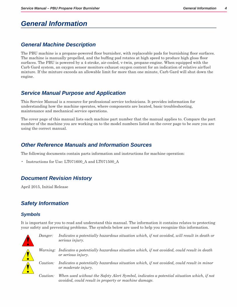
It is important for you to read and understand this manual The information it contains relates to protecting your safety and preventing problems The symbols below are used to help you recognize this information
Danger: Indicates a potentially hazardous situation which, if not avoided, will result in death or serious injury.
Warning: Indicates a potentially hazardous situation which, if not avoided, could result in death or serious injury.
Caution: Indicates a potentially hazardous situation which, if not avoided, could result in minor or moderate injury.
Caution: When used without the Safety Alert Symbol, indicates a potential situation which, if not avoided, could result in property or machine damage.

General Information 5Service Manual – PBU Propane Floor Burnisher
General Safety Messages
Anyone operating the machine should read the following carefully and be informed of potentially dangerous operating conditions Operators should be familiar with the location and use of all safety devices on the machine Do not use the machine if it is not in proper operating condition, and report any damage or operation faults immediately
Danger: − Never operate this machine without proper ventilation. It is the responsibility of the machine operator, machine owner, and the site manager to ensure that the air exchange system where the machine is to be used is in compliance with local building codes and is operating properly. Failure to operate this machine in a well-ventilated area could lead to sickness, injury, or death from carbon monoxide exposure.
− This machine emits Carbon Monoxide (CO), which is colorless, odorless, non-irritating gas. The first symptoms of CO exposure include headache, drowsiness, dizziness, and nausea. If you should experience any of these symptoms while operating the machine, shut off the machine and go outside to get fresh air. Have the machine tested for CO emissions by a qualified service technician before using it again.
− Prolonged or high exposure to CO may result in vomiting, confusion, and collapse in addition to loss of consciousness and muscle weakness. If such symptoms occur, call 911 for emergency medical attention. If you have experienced these symptoms, DO NOT operate this machine or any other propane machine again until cleared by a physician. Excessive exposure to CO can result in death.
Warning: − Propane is a highly flammable fuel. Keep open flames and ignition sources away from the machine and propane tanks. Do not store propane cylinders inside a building. If you smell propane, shut off the machine immediately and take it outside the building.
− Do not use a liquid withdraw propane cylinder or overfill a cylinder to cause it to supply propane in liquid form. This machine is intended to use propane in vapor form. Liquid propane will damage the system and poses a risk of fire. This machine uses a 20lb (9.1kg) capacity aluminum or steel cylinder, which meets the DOT 4E240 standards. Filling should be done only by a qualified propane dealer. Fill through the service valve only. A properly filled cylinder should not exceed 80% of the rated capacity.
Caution: − Do not make unauthorized modifications or alterations to this machine. Nilfisk-Advance assumes no liabilities for injury or damage resulting from an unauthorized modification or alteration to the machine. Any unauthorized modification or alteration to this machine voids all warranties.
− To reduce the risk of burns, stay clear of the engine and exhaust until the machine has cooled.
− When servicing machine, stay clear of moving parts, and do not wear loose clothing. Block machine wheels before raising or jacking up machine. Use hoist stands that will support the weight of the machine. Wear eye and ear protection. Disconnect battery connections before servicing machine. Use only Nilfisk-Advance authorized replacement parts.

General Information 6Service Manual – PBU Propane Floor Burnisher
NameplateThe machine nameplate is located on the interior face of the handle upright, and contains the machine model and serial number
Component LocationsThe following images show the locations of some of the primary components of the machine • Starter Solenoid• Starter• Voltage Regulator• Propane Regulator
• Fuel Cutoff Valve• Oil Dipstick• Oil Pressure Sensor• Oil Filter
• Muffler• Air Filter• Carburetor
Starter Solenoid
Battery
Oil Dipstick
Oil Filter
Oil Pressure Sensor
Starter
Voltage Regulator
Propane Regulator
Fuel Cutoff
Muffler
Air FilterCarburetor
General Information 7Service Manual – PBU Propane Floor Burnisher
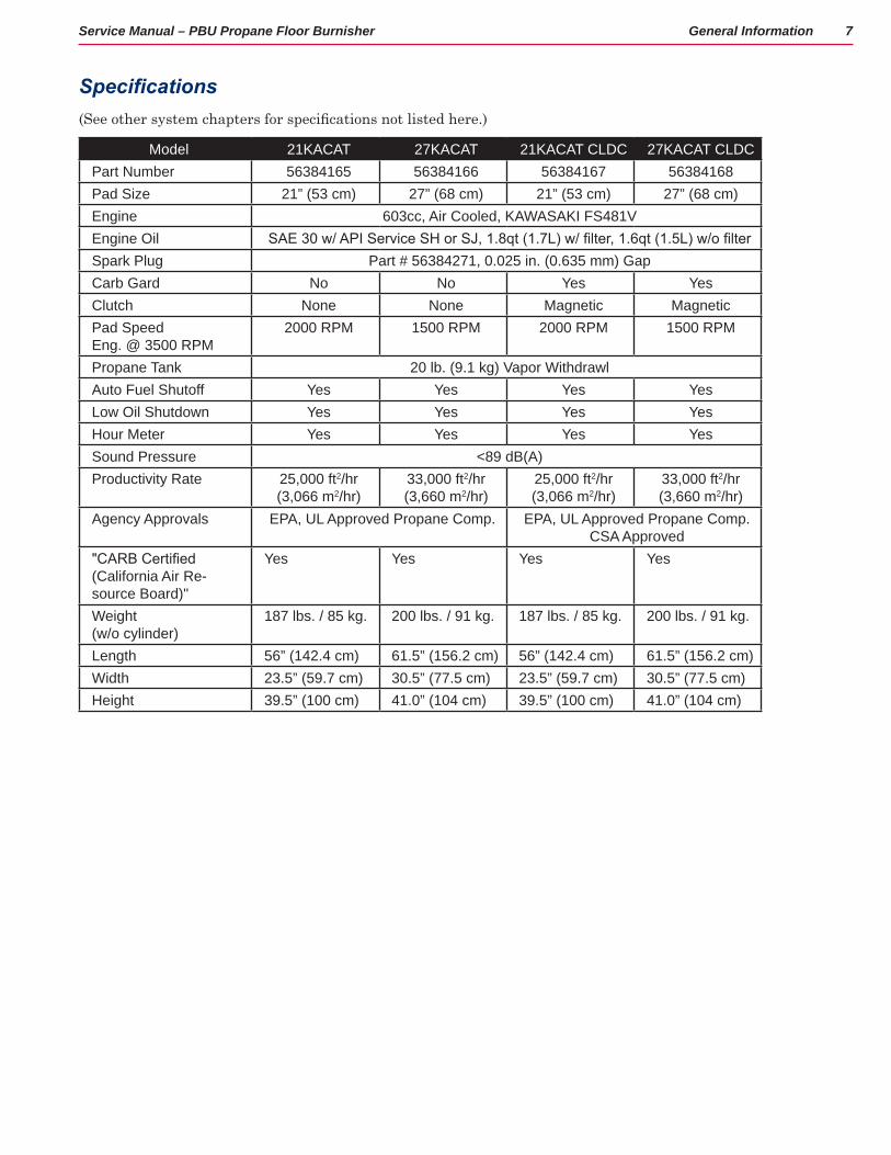
Specifications(See other system chapters for specifications not listed here.)
Model 21KACAT 27KACAT 21KACAT CLDC 27KACAT CLDCPart Number 56384165 56384166 56384167 56384168Pad Size 21” (53 cm) 27” (68 cm) 21” (53 cm) 27” (68 cm)Engine 603cc, Air Cooled, KAWASAKI FS481VEngine Oil SAE 30 w/ API Service SH or SJ, 1.8qt (1.7L) w/ filter, 1.6qt (1.5L) w/o filterSpark Plug Part # 56384271, 0.025 in. (0.635 mm) GapCarb Gard No No Yes YesClutch None None Magnetic MagneticPad Speed Eng. @ 3500 RPM
2000 RPM 1500 RPM 2000 RPM 1500 RPM
Propane Tank 20 lb. (9.1 kg) Vapor WithdrawlAuto Fuel Shutoff Yes Yes Yes YesLow Oil Shutdown Yes Yes Yes YesHour Meter Yes Yes Yes YesSound Pressure <89 dB(A)Productivity Rate 25,000 ft2/hr
(3,066 m2/hr)33,000 ft2/hr (3,660 m2/hr)
25,000 ft2/hr (3,066 m2/hr)
33,000 ft2/hr (3,660 m2/hr)
Agency Approvals EPA, UL Approved Propane Comp. EPA, UL Approved Propane Comp. CSA Approved
"CARB Certified (California Air Re-source Board)"
Yes Yes Yes Yes
Weight (w/o cylinder)
187 lbs. / 85 kg. 200 lbs. / 91 kg. 187 lbs. / 85 kg. 200 lbs. / 91 kg.
Length 56” (142.4 cm) 61.5” (156.2 cm) 56” (142.4 cm) 61.5” (156.2 cm)Width 23.5” (59.7 cm) 30.5” (77.5 cm) 23.5” (59.7 cm) 30.5” (77.5 cm)Height 39.5” (100 cm) 41.0” (104 cm) 39.5” (100 cm) 41.0” (104 cm)

General Information 8Service Manual – PBU Propane Floor Burnisher
Maintenance Schedule
ITEM
IntervalDaily 8 Hour
(Break In)Every
25 Hours
Every 50
Hours
Every 100
Hours
Every 200
Hours
Every 300
HoursCheck or clean air intake screen •Check for fuel and oil leakage •Check for loose or lost nuts and screws
•
Tighten nuts and screws •Check battery electrolyte level •Check and add engine oil •Change engine oil • •Change oil filter •Clean air cleaner foam element •Replace air cleaner paper element •Check pad driver for loose parts • •Check belt for wear or slippage • •Check engine pulley for tightness • •
Check wheel bolts • •Check engine mount bolts • •Check handle bolts • •Check for leakage of engine oil at the various seals
• •
Change dust control filter •Check and adjust engine valve clearance
•
Clean and lap valve seating surface •Clean dust and dirt from cylinder and cylinder head fins
•
Clean and re-gap spark plugs •Clean combustion chambers •Return machine to authorized service center for overall checkup.
•

Burnishing System 9Service Manual – PBU Propane Floor Burnisher
Burnishing System
Functional DescriptionThe burnishing system consists of a replaceable burnishing pad and pad holder, which is driven by a belt from the engine’s output shaft Belt tension is controlled by a spring loaded idler pulley Some units are equipped with a clutch on the engine output shaft to disconnect the drive pulley when not in use The clutch is electrically actuated, and controlled by a switch on the operator’s handle Units equipped with dust control have an aluminum shroud which covers most of the burnisher drive components
Component Locations• Burnishing Disk Pulley
• Tensioner/Idler Pulley
• Drive Belt
• Engine Shaft
• Drive Pulley
• Drive Pulley with Clutch
Burnishing Disk Pulley
Drive Belt
Tensioner/ Idler Pulley
Engine Shaft/ Drive Pulley
Drive Pulley With Clutch
Burnishing System 10Service Manual – PBU Propane Floor Burnisher
Troubleshooting
Problem Cause Correction• Burnishing pad turns
slow• Machine seems
underpowered
When the drive belt slips the pad will rotate slower than normal. Even though this doesn’t actually affect the engine, it can seem like the engine has lost power.
• Inspect the drive belt for glazing (smooth glassy surface on the tapered faces). Replace the drive belt if glazed.
• Inspect the belt tensioner for proper operation, and that the drive belt appears to be properly tensioned. Clean or replace the tensioner if it cannot maintain proper belt tension.
• If so equipped, inspect the drive clutch for slipping. See below for more details.
For clutch-equipped machines, the burnishing pad does not engage, is slow to engage, sporadic, or turns slowly.
A problem with the clutch will present itself with one of these symptoms. Either the clutch is faulty or it is not getting a proper electrical connection.
• See below for troubleshooting.
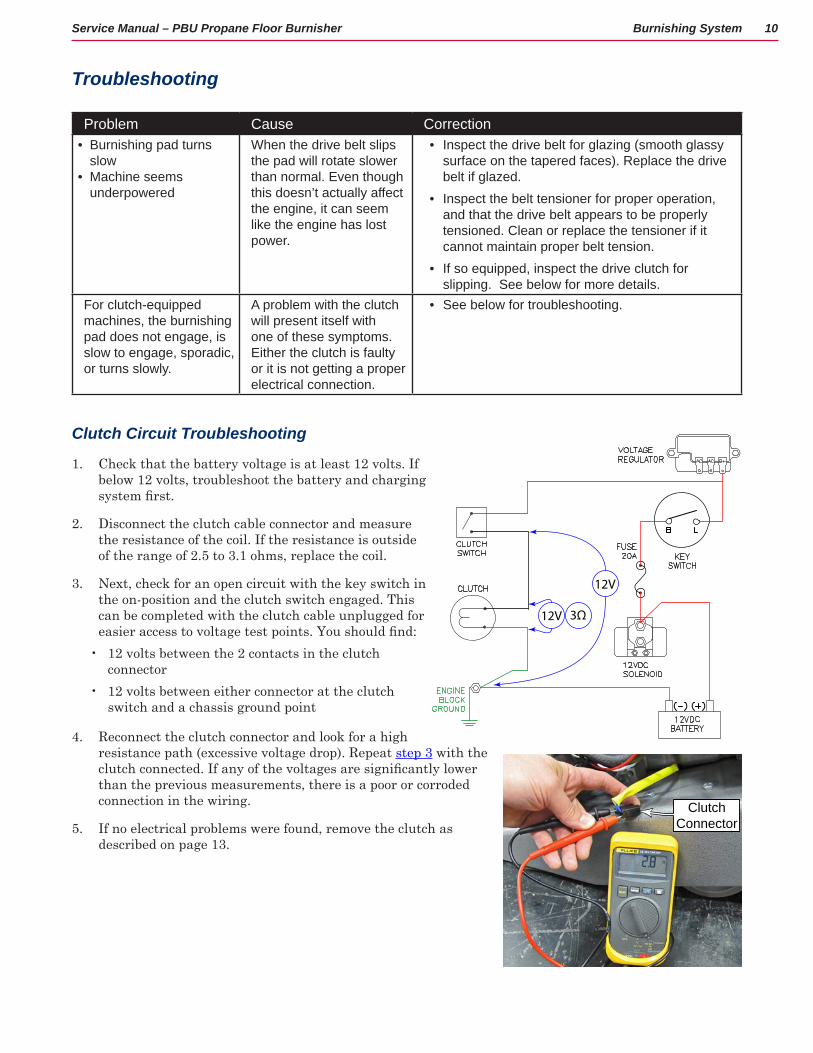
Clutch Circuit Troubleshooting
1 Check that the battery voltage is at least 12 volts If below 12 volts, troubleshoot the battery and charging system first.
2 Disconnect the clutch cable connector and measure the resistance of the coil If the resistance is outside of the range of 2 5 to 3 1 ohms, replace the coil
3 Next, check for an open circuit with the key switch in the on-position and the clutch switch engaged This can be completed with the clutch cable unplugged for easier access to voltage test points. You should find:
• 12 volts between the 2 contacts in the clutch connector
• 12 volts between either connector at the clutch switch and a chassis ground point
4 Reconnect the clutch connector and look for a high resistance path (excessive voltage drop) Repeat step 3 with the clutch connected. If any of the voltages are significantly lower than the previous measurements, there is a poor or corroded connection in the wiring
5 If no electrical problems were found, remove the clutch as described on page 13
12V
12V
3Ω
Clutch Connector

Burnishing System 11Service Manual – PBU Propane Floor Burnisher
Removal and Installation
Burnishing Pad Holder
The burnishing pad holder may need to be replaced if it becomes damaged and no longer holds the burnishing pad securely It may also need to be removed as a prerequisite to other maintenance procedures
1 Close the propane service valve and remove the propane tank
2 Stand the machine on its back in the pad change position
3 Remove the burnishing pad from the pad holder
4 Place a 3/4" open end wrench on the top of the burnishing shaft to hold the shaft from turning
5 Wear gloves to protect your hands from the gripping spines on the pad holder
6 Unscrew the pad holder from the shaft in a normal counterclockwise direction

Burnishing System 12Service Manual – PBU Propane Floor Burnisher
Drive Belt
The drive belt needs to be replaced if it becomes worn, frayed, or glazed Glazing is caused by the belt slipping against the pulleys, which causes the belt to slip even more A glazed belt has a shiny texture of the sloped edges that contact the pulleys
1 Close the propane valve, tip the machine up into the pad change position, and remove the Burnishing Pad Holder described on page 11
2 For models with Dust Control, remove the pulley cover by removing the 4 screws, washers, and lock washers
3 For machines with dust control, loosen but do not remove, the tensioner arm bolt so the belt can fit between the idler pulley and the dust shroud. Skip step 4 below
Tension Arm Bolt
Burnishing Pad Shaft
4 Place a 9/16” box wrench on the idler pulley shaft bolt, and rotate the tensioning arm counterclockwise to de-tension the drive belt
5 Roll the belt off the main pulley It may be helpful to use a screw driver to get it started
6 Remove the belt from the engine pulley
• For Dust Control models, remove the belt from above the dust shroud by pulling it out toward the engine pulley
• You may need to loosen the tensioner pulley mounting bolt to permit the belt to fit between the pulley and dust shroud When repositioning the tensioner, make sure the alignment pin is inserted into the hole in the burnishing deck
7 Before replacing the belt, check the movement of the tensioning arm to make sure it moves freely
Pulley Cover
Dust Control Model
Burnishing Spindle
Idler Pulley
9/16” Wrench
Screw Driver

Burnishing System 13Service Manual – PBU Propane Floor Burnisher
Burnishing Clutch
The burnishing clutch is an optional accessory on models with dust control It is a 12 volt magnetically actuated clutch that disengages the burnishing drive when not in use
1 Close the propane valve, tip the machine into the pad change position, and remove the Burnishing Pad Holder described on page 11
2 Before removing the drive belt, you may want to loosen (but don’t remove) the clutch retaining bolt With the belt in place, the burnishing pulley can be used to help keep the motor shaft from rotating while you loosen the bolt if the clutch is engaged
• If available, an impact driver works best for loosening the bolt while taking the least amount of effort to keep the motor shaft from turning
3 Remove the Drive Belt described on page 12
4 Disconnect the clutch cable connector located behind the propane regulator
5 Loosen the 3 engine mounting bolts just enough to raise the engine and extract the clutch cable through the opening in the deck
• Alternatively, you could remove the clutch wires from the cable connector and remove the cable without lifting the engine
6 Finish removing the clutch retaining bolt and remove the clutch from the motor shaft
7 During replacement:
• Make sure the spacer washer is in place on the engine shaft between the engine and the clutch
• Use Loctite 243 on the clutch retaining bolt
• Torque the clutch retaining bolt to 40 ft-lbs
Clutch Switch
1 Remove the 4 screws that secure the cover to the switch enclosure and remove the cover and switch
2 Disconnect the two wires from the switch During replacement, note that there is no polarity for the wires
3 Slide the switch off the 2 mounting pins
Retaining Bolt
Engine Bolts (3)
Clutch Cable
Mounting Pins
Clutch Switch

Engine System 14Service Manual – PBU Propane Floor Burnisher
Engine System
Component Locations• Starter Solenoid• Starter• Voltage Regulator• Propane Regulator
• Fuel Cutoff Valve• Oil Dipstick• Oil Pressure Sensor• Oil Filter
• Muffler• Air Filter• Carburetor
Starter Solenoid
Battery
Oil Dipstick
Oil Filter
Oil Pressure Sensor
Starter
Voltage Regulator
Propane Regulator
Fuel Cutoff
Muffler
Air FilterCarburetor

Engine System 15Service Manual – PBU Propane Floor Burnisher
Maintenance and AdjustmentsThis section includes maintenance and adjustment procedures associated with routine maintenance Additional procedures are located within the mechanical sections of this chapter
Maintenance Specifications
The table below contains a quick reference for common maintenance parameters Also refer to the complete list of Specifications described on page 7 and the Engine Specifications described on page 46
Quick Reference ParametersParameter Value ReferenceLow Idle Speed 1800 - 2000 rpm page 25
High Idle Speed3400 - 3450 rpm @ 21”3450 - 3550 rpm @27”
page 25
Oil Grade SJ or higher
page 17Viscosity SAE 30Capacity w/o filter 1.5L (1.6 US qt)Capacity w/ filter 1.7L (1.8 US qt)Spark Plug NGK BPR4ES
page 18Spark Plug Gap 0.6 mm (0.025 in)Spark Plug Torque 22 N•m (16 ft•lb)
Coil Air Gap 0.2 - 0.4 mm (0.008 - 0.016 in.) page 33
Valve Clearance 0.10 - 0.15 mm (0.004 - 0.006 in.) page 38
Min. Cyl. Compression 483 kPa (70 psi) page 35
Cooling Air Filter
The cooling filter should be cleaned every 1 engine-hour. It is also a good practice to clean the cooling air filter when ever the machine is serviced Restrictions in the airflow can result in the engine to run hotter than normal.
1 Carefully pull the filter off the top of the engine, taking care not to damage the Velcro fasteners
2 Brush off large debris from the filter surface.
3 The filter may be washed with light detergent (dish soap) and water
4 Squeeze out excess water. Do not wring the filter as this can tear the foam or damage the Velcro tabs
5 Set the filter aside to dry before reinstalling it.
Cooling Filter
Hook and Loop Tabs

Engine System 16Service Manual – PBU Propane Floor Burnisher
Intake Air Filter
The engine air intake has a 2-stage air filter: A washable pre-filter and a disposable main filter. The main filter prevents fine dust from entering the engine, and the pre-filter increases the life of the main filter by keeping coarse debris from clogging the filter.
1 Rotate the two knobs on the filter cover 1/4-turn counterclockwise, and remove the cover
2 Loosen the upper clamp and remove the filter from the plenum, or optionally, loosen the lower clamp and lift the filter and air plenum up off the carburetor. You may find this easier than trying to remove the filter from the plenum.
3 Slide the foam pre-filter off the main filter. The pre-filter may be washed with mild soap (dish soap) and water
4 Thoroughly dry the pre-filter.• Do not wring the filter, as this can tear the foam.• Do not install the pre-filter over the main filter unless
it is completely dry. Moisture from the pre-filter can damage the paper of the main filter.
• Replace the pre-filter if it becomes torn or damaged.
5 If the main filter is relatively clean, it can be vacuumed off and replaced (do not use compressed air) However, if the filter media appears darkened, it should be replaced.
6 Make sure the pre-filter is completely dry, and reinstall it over the main filter.
7 Reinstall the main filter assembly onto the engine.
Filter Cover
Engine Filter
Upper Clamp
Lower Clamp
Air Plenum
Main Filter
Pre-Filter

Engine System 17Service Manual – PBU Propane Floor Burnisher
Oil and Filter Change
The oil should be changed every 50 engine-hours, and the oil and filter should be changed every 100 engine-hours (every other oil change)
Oil Change ParametersOil Grade SJ or higherViscosity SAE 30Capacity w/o filter 1.5L (1.6 US qt)Capacity w/ filter 1.7L (1.8 US qt)
1 Run the engine for a couple minutes to warm it, but not so hot that it is difficult to work on.
2 Tilt the machine back on its rear casters (pad off the floor), and chock the wheels to keep it from rolling
3 Remove the end cap from the oil drain, and place a 1/2” plastic tube on the oil drain to extend the drain away from the burnishing deck
4 Place a container under the end of the tube to capture the used oil
5 Rotate the quick-release oil drain valve 1/8-turn and pull it outward about 1/2-inch to release the valve The oil should begin to drain into the catch container
6 Continue to drain as much of the old oil as possible until the tube stops dripping
7 Close the quick-release valve, remove the tube, and replace the drain cap
8 If the oil filter is not being changed, skip to step 14 below
9 Slightly loosen the oil filter using a small oil filter wrench.
• If necessary, disconnect the oil pressure sensor wires to avoid bending the terminals
10 Tilt the burnisher slightly on its left side to avoid dripping oil on the engine crankcase
11 Finish removing the oil filter, taking care keep it upright, as it contains a significant amount of oil.
12 Using your finger, apply a small amount of clean oil to the O-ring on the new oil filter to lubricate it, and install the new filter.
13 Tighten the oil filter to 11.8 N•m (8 5 ft•lbs), or approximately 3/4-turn more after the O-ring first touches the crankcase. Do not overtighten the oil filter.
14 Remove the dipstick and add oil (see capacity above) through the fill spout.
15 Run the engine for about a minute and recheck the dipstick level
Drain Cap
Drain Valve
Oil Filter
Dipstick and Fill Spout
Oil Pressure Sensor
Engine System 18Service Manual – PBU Propane Floor Burnisher
Spark Plug Change
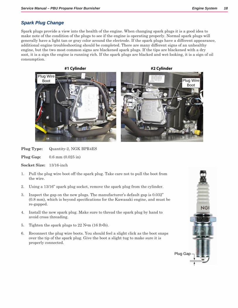
Spark plugs provide a view into the health of the engine When changing spark plugs it is a good idea to make note of the condition of the plugs to see if the engine is operating properly Normal spark plugs will generally have a light tan or gray color around the electrode If the spark plugs have a different appearance, additional engine troubleshooting should be completed There are many different signs of an unhealthy engine, but the two most common signs are blackened spark plugs If the tips are blackened with a dry soot, it is a sign the engine is running rich If the spark plugs are blacked and wet-looking, it is a sign of oil consumption
#1 Cylinder #2 Cylinder
Plug Wire Boot Plug Wire
Boot
Plug Type: Quantity-2, NGK BPR4ES
Plug Gap: 0 6 mm (0 025 in)
Socket Size: 13/16-inch
1 Pull the plug wire boot off the spark plug Take care not to pull the boot from the wire
2 Using a 13/16” spark plug socket, remove the spark plug from the cylinder
3 Inspect the gap on the new plugs The manufacturer’s default gap is 0 032” (0.8 mm), which is beyond specifications for the Kawasaki engine, and must be re-gapped
4 Install the new spark plug Make sure to thread the spark plug by hand to avoid cross threading
5 Tighten the spark plugs to 22 N•m (16 ft•lb)
6 Reconnect the plug wire boots You should feel a slight click as the boot snaps over the tip of the spark plug Give the boot a slight tug to make sure it is properly connected
Plug Gap

Engine System 19Service Manual – PBU Propane Floor Burnisher
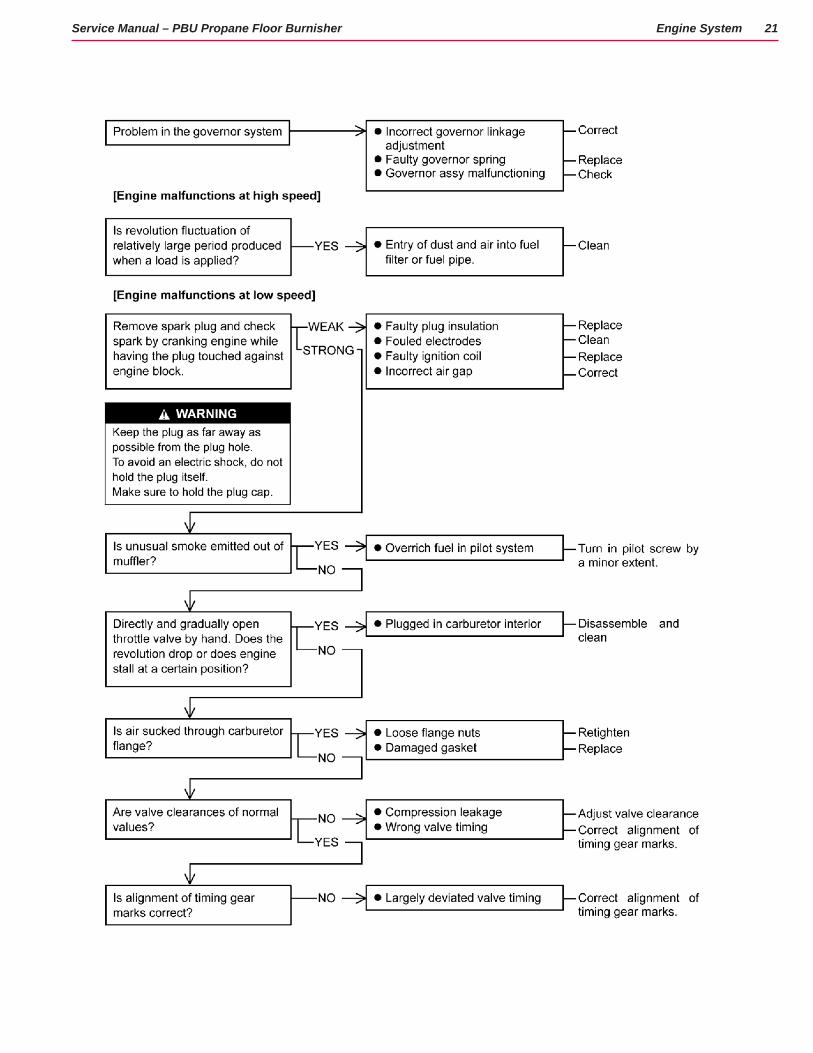
TroubleshootingThe following troubleshooting decision tree is courtesy of Kawasaki and contains information relating to both gasoline and propane engines

Engine System 20Service Manual – PBU Propane Floor Burnisher
Engine System 21Service Manual – PBU Propane Floor Burnisher

Engine System 22Service Manual – PBU Propane Floor Burnisher

Engine System 23Service Manual – PBU Propane Floor Burnisher

Engine System 24Service Manual – PBU Propane Floor Burnisher
Fuel SystemThe PBU fuel system functionally consists of the propane tank, pressure regulator, carburetor, mechanical governor, and operator throttle position selector The fuel (propane) is stored in the tank as a liquid, but is dispensed into the fuel system as a gas The fuel pressure in the tank is much too high to be used by the engine The pressure regulator reduces the pressure of the gas before it is delivered to the carburetor
The pressure regulator does more than just reduce the pressure, however It also meters the amount of fuel being delivered to the engine based on the demand for fuel by the engine When the engine isn’t calling for fuel, the diaphragm (valve) inside the pressure regulator stays closed, and no fuel is delivered When the engine causes a small vacuum in the carburetor during the intake cycle, the diaphragm is opened and fuel begins to flow. The amount of fuel flowing is proportional to the amount of vacuum from the carburetor.
In a sense, the pressure regulator is like a mechanical amplifier. A small amount of vacuum at the outlet is able to control the large pressure at the inlet (the tank). The adjustments to the regulator fine tune the ratio of this small vacuum to the control of the high pressure
The carburetor mixes the fuel and air in the proper proportion for combustion by the engine A small metering jet in the carburetor controls the ratio of fuel to air, and a butterfly valve controls the total volume of fuel/air that is permitted to enter the engine The position of the butterfly valve is controlled by the mechanical governor
The governor is inside the engine and operates on centrifugal force The faster the engine turns, the more the governor tries to close the carburetor’s butterfly valve. Conversely, a spring connected to the operator’s throttle position lever tries to pull the butterfly valve open When these two forces are balanced, the engine will run at constant speed even when the load on the engine changes When the engine gets loaded, the speed drops and the governor doesn’t pull the butterfly closed as hard, causing the valve to open more, and more fuel/air to enter the engine
To prevent fuel from flowing to the engine when the engine isn’t running, there are two fuel lockouts. The first is an electric valve that opens only when the ignition is turned on. The second is a vacuum lockout that prevents fuel from flowing if there is no vacuum present at the carburetor.
Throttle Cable Position
The most common reasons for performing this adjustment are if the throttle cable has been replaced, or if the cable clamp has loosened over time This procedure adjusts the effective length of the cable for full throttle movement
1 Place the throttle selector into the Slow-position, but do not force it if it doesn’t go all the way into position
2 Loosen the cable clamping screw
3 Make sure that both the Throttle Selector and the Throttle Link Arm are in their lowest position, and then retighten the cable clamping screw
4 Make sure the Throttle Selector can be moved through its full range without causing the cable to slip under the clamp
Butterfly Valve
Metering Jet
Vacuum Lockout
Fuel Inlet
Cable Clamp
Throttle Position Link Arm
Low Limit

Engine System 25Service Manual – PBU Propane Floor Burnisher
Throttle High Idle Position
This adjustment sets the upper limit of the Throttle Position Link Arm, which indirectly controls the high idle speed of the engine via the governor This adjustment may be completed on its own, or as a followup adjustment to adjusting the fuel mixture described on page 26
1 Start the engine and bring it up to operating temperature
2 Make sure the burnishing pad is raised so there is no load on the engine
3 Move the throttle selector to Fast
4 Loosen the jamb nut and adjust the high limit screw until the engine tachometer reads the correct engine speed listed below Loosen the screw to increase speed, or tighten the screw to decrease speed
• 21” machines: 3400 to 3450 rpm• 27” machines: 3450 to 3550 rpm
5 Retighten the jamb nut
Carburetor Low Idle
Unlike the High Idle Position that indirectly controls the engine RPM via the governor, the Low Idle adjustment acts directly on the carburetor butterfly valve to set the minimum butterfly position for engine idle This adjustment may be completed on its own, or as a followup adjustment to adjusting the fuel mixture described on page 26
1 Make sure the Throttle Cable Position described on page 24 is correct
2 Start the engine and bring it up to operating temperature
3 Make sure the burnishing pad is raised so there is no load on the engine
4 Move the throttle selector to Slow
5 Adjust the Low Idle adjustment screw until the engine idles at 1800 to 2000 rpm Loosen the screw to decrease the rpm, or tighten the screw to increase the rpm
Throttle Position Link Arm
High Limit Screw
Jamb Nut
Low Idle Screw
Butterfly Valve Linkage
Engine System 26Service Manual – PBU Propane Floor Burnisher
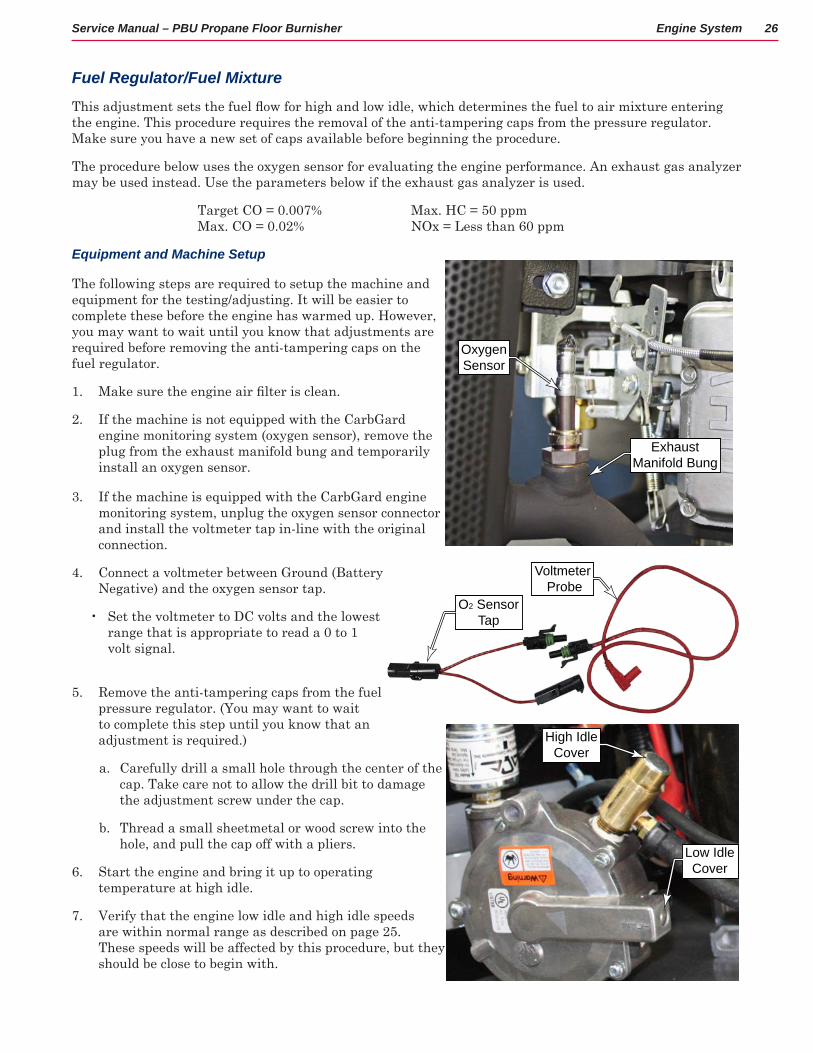
Fuel Regulator/Fuel Mixture
This adjustment sets the fuel flow for high and low idle, which determines the fuel to air mixture entering the engine This procedure requires the removal of the anti-tampering caps from the pressure regulator Make sure you have a new set of caps available before beginning the procedure
The procedure below uses the oxygen sensor for evaluating the engine performance An exhaust gas analyzer may be used instead Use the parameters below if the exhaust gas analyzer is used
Target CO = 0 007% Max CO = 0 02%
Max HC = 50 ppm NOx = Less than 60 ppm
Equipment and Machine Setup
The following steps are required to setup the machine and equipment for the testing/adjusting It will be easier to complete these before the engine has warmed up However, you may want to wait until you know that adjustments are required before removing the anti-tampering caps on the fuel regulator
1 Make sure the engine air filter is clean.
2 If the machine is not equipped with the CarbGard engine monitoring system (oxygen sensor), remove the plug from the exhaust manifold bung and temporarily install an oxygen sensor
3 If the machine is equipped with the CarbGard engine monitoring system, unplug the oxygen sensor connector and install the voltmeter tap in-line with the original connection
4 Connect a voltmeter between Ground (Battery Negative) and the oxygen sensor tap
• Set the voltmeter to DC volts and the lowest range that is appropriate to read a 0 to 1 volt signal
5 Remove the anti-tampering caps from the fuel pressure regulator (You may want to wait to complete this step until you know that an adjustment is required )
a Carefully drill a small hole through the center of the cap Take care not to allow the drill bit to damage the adjustment screw under the cap
b Thread a small sheetmetal or wood screw into the hole, and pull the cap off with a pliers
6 Start the engine and bring it up to operating temperature at high idle
7 Verify that the engine low idle and high idle speeds are within normal range as described on page 25 These speeds will be affected by this procedure, but they should be close to begin with
Oxygen Sensor
Exhaust Manifold Bung
O2 Sensor Tap
Voltmeter Probe
High Idle Cover
Low Idle Cover

Engine System 27Service Manual – PBU Propane Floor Burnisher
Low Idle Mixture
1 Starting with a warm engine running at high idle, bring the throttle selector to the Slow position
2 Check the voltage of the oxygen sensor It should be between 35 and 50 mV (0 035 - 0 050 V)
3 If the oxygen sensor voltage is out of range, turn the Low Idle Mixture screw with increments of 1/4 to 1/2 turn at a time, and waiting for about 30 seconds between increments for the change to take effect
• Low Voltage: Turn the screw clockwise This will increase (richen) the fuel mixture
• High Voltage: Turn the screw counterclockwise This will decrease (lean) the fuel mixture
4 After the mixture has been changed, it is likely that the low-idle speed will change Readjust the Carburetor Low Idle described on page 25
High Idle (Full Load) Mixture
1 Starting with a warm engine running at high idle, load the machine by operating the burnishing pad on a floor surface.
2 While the machine is loaded, observe the voltage reading from the oxygen sensor The voltmeter reading should be between 50 and 60 mV (0 050 to 0 060 V)
3 If the oxygen sensor voltage is out of range, turn the high limit fuel adjustment screw (triangular head screw) in 1/4-turn increments
• Loosen the setscrew on the back of the outlet that locks the adjustment screw
• Low Voltage: Turn the screw counterclockwise This will increase (richen) the fuel mixture
• High Voltage: Turn the screw clockwise This will decrease (lean) the fuel mixture
4 After each screw-turn increment, recheck the oxygen sensor voltage with the machine operating under load
5 Retighten the locking setscrew that prevents the adjustment from turning
6 After the mixture has been changed, it is likely that the high-idle speed will change Readjust the Throttle High Idle Position described on page 25
7 Replace both of the anti-tampering caps on the regulator
Low Idle Screw
Small Setscrew
High Idle Screw

Engine System 28Service Manual – PBU Propane Floor Burnisher
Intake Manifold
Removing the intake manifold is frequently a prerequisite procedure for removing the cylinder heads This procedure is based on the minimal amount of disassembly necessary to remove the manifold You may optionally choose to remove the carburetor from the manifold
1 Shut off the propane service valve
2 Remove the “Intake Air Filter” (including the plenum elbow) as described on page 16
3 Disconnect the fuel line and vacuum line from the carburetor
4 Disconnect the throttle spring from the governor arm
5 Disconnect the butterfly link and spring from the governor arm
6 Remove the nut (A) and screw (B) that secure the throttle plate to the manifold, and remove the throttle plate If you prefer to completely remove the throttle plate from the machine, remove the throttle cable as you remove the throttle plate
7 Remove the 4 screws that secure the intake manifold to the heads, and remove the manifold and carburetor
8 During replacement, clean the mating surfaces and replace the manifold gaskets with new gaskets
Fuel Line
Throttle Spring
Vacuum Line
A
B
Butterfly Link and Spring
Governor Arm
Throttle Plate
Throttle Cable
Carburetor
Intake Manifold

Engine System 29Service Manual – PBU Propane Floor Burnisher
Exhaust System
Muffler/Exhaust Manifold
Caution: To avoid risk of serious burn, do not work on the exhaust until the engine has cooled.
1 Remove the 2 bolts and washers (B) that secure the support bracket (C) to the #2 cylinder head
2 Optionally, remove the bolt, washers, and nut (D) that secures the support bracket (C) to the muffler (A), and remove the bracket.
3 Remove the 4 nuts and washers (E) that secure the manifold to the cylinder exhaust flanges, and carefully lower the exhaust from the studs and remove the exhaust
4 During replacement, clean the flanges and replace the flange gaskets (F).
B
C
EF
D
A

Engine System 30Service Manual – PBU Propane Floor Burnisher
Ignition/Electrical System
Starter
The starter consists of a 12-volt motor which drives a pinion gear to engage the flywheel of the engine to turn the engine. The pinion gear is mounted to a bendix drive, which is a spiral gear When the motor first turns, inertia keeps the pinion gear from rotating, but this causes the pinion gear to climb up the spiral bendix When the pinion gear is at the top of the bendix, it is aligned with the engine’s flywheel, and engages with it to turn the engine As soon as the engine begins to turn on its own, which is faster than the starter motor, the pinion gear is spun backward, which causes it to climb down the bendix spiral, and move away from the flywheel.
If the starter motor spins but doesn’t engage with the engine, it is typically the bendix drive or pinion gear that are damaged
1 To avoid accidental shorting of the starter wire, remove the battery-negative terminal from the battery
2 Remove the two bolts that secure the starter to the engine housing, and lower the starter to remove it
3 Remove the nut that secures the power wire to the motor terminal, and remove the wire
4 Inspect the pinion gear for chipped or damaged teeth If damaged, replace the starter
5 Inspect the bendix drive for smooth operation Apply a small amount of grease to the bendix spiral and move the pinion gear up and down to spread it
6 During replacement, don’t forget to install the engine lifting hook on the back mounting bolt, and the ground wire to the front mounting bolt
Pinion Gear
Bendix
Bendix Spring
Battery Negative
Lifting Hook
Mounting Bolts
Ground Wire
Positive Wire

Engine System 31Service Manual – PBU Propane Floor Burnisher
Voltage Regulator
The voltage regulator takes the AC voltage from the engine’s generator and converts it to DC power and reduces the voltage to approximately 14 1 volts (DC) The most common sign of a failed voltage regulator is that battery voltage is not between 13 to 15 volts when the engine is running
Initial symptoms of a failing regulator is a frequent dead battery However, before concluding that the regulator is bad, first make sure the battery is in good condition and properly charged
Troubleshooting
1 With the engine not running, make sure the battery is not the problem The battery voltage should be 12 volts If the voltage is less than 11 volts, a battery problem should not be ruled out
2 Start the engine and bring it to high-idle
3 With a voltmeter set to AC volts, measure the voltage between terminals A and B The voltage should be between 26 to 34 volts AC
4 Set the voltmeter to DC volts, and check the voltage between terminal C and Ground This voltage should be between 13 to 15 volts DC If the voltage is outside of this range, then replace the voltage regulator
Replacement
1 Disconnect the generator connector from Terminals A and B
2 Disconnect the battery wire from terminal C
3 Remove the two screws that secure the voltage regulator to the engine housing, and remove the regulator
4 During replacement, make sure the ground wire (coming from the starter motor) is connected under the left-hand mounting screw
VoltageRegulator
EngineGenerator
EngineGround
12 VoltBattery
StarterSolenoid
20 AmpFuse
KeySwitch26 to 34 VAC
13 to 15 VDC
Battery Positive
Ground
AC Input from Generator
A B C

Engine System 32Service Manual – PBU Propane Floor Burnisher
Ignition Coil
Troubleshooting
The ignition coil is self-contained with no serviceable components So troubleshooting should be limited to pass/fail and component replacement Contrary to intuition, the ignition keyswitch does not provide power to the ignition coil Instead, the keyswitch grounds the coil circuit when the engine is not supposed to be running, and opens the circuit (no connection) when the engine should run Therefore, the two failure modes of the ignition keyswitch wire are as follows:
• Short to Ground: Engine never starts• Open Circuit (or short to positive): The engine doesn’t stop normally, because the coil circuit would not
be grounded when keyswitch is turned off (The engine would still stop because fuel is shut off at the fuel cutoff )
1 To check whether there is a problem (short to ground) with the ignition (keyswitch) wire, unplug the wire from the coil and see if the engine starts If the engine starts only when the wire is disconnected, then trace the wire to look for a short to ground
Caution: Do not touch the spark plug wire while cranking the engine or you will likely receive a shock.
2 With the fuel service valve closed, check for spark by cranking the engine for no more than a couple seconds at a time:
• If an ignition spark tester is available, connect one end of the spark tester to the spark plug wire and the other end to a good ground Crank the engine and look for a spark at the tester
• If an ignition spark tester is not available, use a fresh spark plug, connect it to the spark plug wire and use a jumper wire to ground the metal base of the spark plug Crank the engine and look for a spark at the tip of the plug
3 An alternative check for the coil is to measure the coil resistance • Secondary Winding: Between the spark plug wire and ground (S & G) should be 10 - 20 kΩ• Primary Winding: Between ignition wire
and ground (K & G) should be 3 -13 kΩ• Both Windings: Between the ignition wire
and spark plug wire (K & S) should be between 18 - 28 kΩ
4 If the ignition coil does not generate a spark, replace the coil as described below
5 If the ignition coil produces a weak spark, the check/adjust the coil air gap as described below
6 If neither cylinder has spark and both coils are deemed good, then the flywheel is bad.
Spark Coil Wire
Ground Jumper
Trig
ger
KeyswitchS
G K
MagnetSN

Engine System 33Service Manual – PBU Propane Floor Burnisher
Replacement
1 Remove the Intake Air Filter described on page 16
2 Remove the 5 screws that secure the fan cover to the engine, and remove the cover Note the position of the wire clamp and oil dipstick for the replacement
3 Unplug the ignition wire (A) from the coil
4 Disconnect the spark plug wire (B) from the spark plug
5 Remove the 2 screws (C) that secure the coil to the engine housing and remove the coil (D)
6 During replacement, inspect and clean the area around the mounting screws to ensure a proper grounding connection
7 Before tightening the mounting screws, perform the air gap adjustment below
Air Gap Adjustment
The ignition coil functions as a magnetic impulse generator As the permanent magnets embedded in the flywheel pass by the coil, they induce a voltage in the coil. The distance between the coil and the magnets determine the strength of the electrical impulse. If the air gap is too small, the coil or flywheel can contact and become damaged If the gap is too large, the spark will be weak
1 Rotate the engine flywheel until the permanent magnet is lined up in front of the ignition coil
2 Using a feeler gauge, set the gap between the magnet and coil The gap should be the same for all 3 iron core posts (left/middle/right)
Ignition Coil Air Gap: 0 2 - 0 4 mm (0 008 - 0 016 in )
3 Because the coil will want to rotate clockwise as you tighten the screws, it is best to begin tightening the left (counterclockwise-left) screw first.
Torque: 5 9 N•m (52 in•lb)
4 After the left screw is tight, recheck the right air gap, and tighten the right screw
Air Filter Oil
Dipstick
Wire Clamp
C
D
A
C
B

Engine System 34Service Manual – PBU Propane Floor Burnisher
CarbGard System
CarbGard is an emissions monitoring device that monitors the exhaust emissions and will shut the engine down if the oxygen level is too low or too high The oxygen sensor must reach operating temperature before it will start to send signals to the CarbGard module A unit may shut down at a cold start up after one minute because the oxygen sensor did not reach required temperature to start to send a signal
The oxygen sensor creates a small voltage based on the amount of oxygen present The sensor’s output ranges from 0 1 volts (lean) to 0 9 volts (rich)
The output of the CarbGard module acts like a switch in the engine safety circuit When the switch is closed, the circuit is complete and the electric fuel lockout valve will be open to permit fuel to the engine The CarbGard switch is in series with the oil pressure switch, so that if either switch opens, the circuit is broken and the fuel cutoff valve will close
Control
CarbGard Module

Engine System 35Service Manual – PBU Propane Floor Burnisher
Top End, HeadsCompression Test
A compression test is used to determine the health of the engine The engine pistons make compression as part of their normal combustion cycle
You will need a compression tester (pressure gauge) with a 14mm fitting (standard spark plug thread) The tester should have a pressure release valve so you can release the pressure before disconnecting the gauge
1 Make sure the battery is fully charged and in good condition You want the engine cranking speed to be consistent throughout the test
2 Start the engine and bring it up to operating temperature The engine components fit and seal differently when the engine is hot versus cold
3 Shut the engine off and close the service valve on the propane tank You do not want fuel entering the engine for this test
4 To protect the ignition coils and to avoid being shocked, disable the ignition circuit by grounding the ignition terminal on both coils Disconnect the ignition wire from the coils and replace it with a jumper to ground
5 Set the throttle selector lever to Fast. You want the butterfly valve in the carburetor wide open to permit maximum air to enter the cylinder
6 Remove both spark plugs from their cylinders
7 Thread the compression tester into the first spark plug port.
• It is not necessary to tighten the gauge with tools. Use firm hand-tightening until the gauge is fully seated
• Make sure the gauge is reading zero before you begin Press the pressure release button to release pressure (The gauge contains a schrader valve So it will hold pressure even when disconnected )
8 Turn the ignition key to the start position and crank the engine for 5 complete cycles (approximately 5 seconds)
• You should see the pressure gauge pulse with each compression stroke of the engine
• Make note of at least the first and final compression pulses. The difference between the first and last pulse may be helpful during diagnostics and evaluation of the test
9 Move the compression tester to the second cylinder and repeat the test Don’t forget to release the pressure from the gauge before repeating the test
10 Refer to the “Interpreting the Results” section below for analysis, and also to determine whether a “Wet Test” should be completed
Pressure Gauge
14mm Fitting
Pressure Release
Jumper to Ground
Ignition Coil
Engine System 36Service Manual – PBU Propane Floor Burnisher
Interpreting the Results
• Because compression results will vary from engine to engine, there is no specific “normal” compression value However, the minimum acceptable compression for this engine is: Min Comp: 483 kPa (70 psi) (hot engine)
• High compression is typically a sign of carbon buildup in the cylinder Remove the head and clean buildup from the head and piston crown Also check the Valve Clearance described on page 38
• If the first compression pulse is more than half the total compression after 5 pulses, and the total compression is low, then the most likely cause is a valve that is not closing or sealing properly Check the Valve Clearance described on page 38 Check the Valve and Seat Inspection described on page 42
• If the compression is low, refer to the Wet Test below to isolate whether the cause is rings versus valves
Wet Test
If the compression is low, you may wish to perform a wet compression test by adding a small amount of oil to the cylinder before repeating the compression test The additional oil will improve a poor piston ring seal, but will not improve the seal from a bad valve
Important: For this test to be successful, the small amount of oil must evenly spread across the face of the piston So the machine must be tipped up so that the cylinder is pointing upward It cannot be completed in a horizontal position
1 Tip the machine up so the tested cylinder is facing upward
2 Using a syringe or small oil can, inject about 5mL (1 tablespoon) of clean engine oil into the spark plug port
• Don’t put in too much oil or you could damage your compression tester
• Do Not install a spark plug in the cylinder or you could seriously damage the engine
3 Manually turn the engine a couple of times to help spread the oil across the cylinder
4 Reinstall the compression tester and repeat the compression test
• If the new compression reading did not appreciably increase (less than 5 psi increase), then the problem lies with the valves
• If the compression appreciably increased, then the piston rings are warn or the cylinder walls are scored
5 After the test is complete, crank the engine several times without a spark plug to clear the cylinder

Engine System 37Service Manual – PBU Propane Floor Burnisher
Cooling Fan Cover
Removing the cooling fan cover is a prerequisite to completing many of the engine top-end procedures
1 Remove the Intake Air Filter described on page 16
2 Remove the 5 screws that secure the fan cover to the engine, and remove the cover Note the position of the wire clamp and oil dipstick for the replacement
Valve Cover
1 Remove the 5 screws that secure the valve cover to the head and remove the valve cover
2 During replacement, clean the gasket sealing surfaces, and install a new gasket
3 When installing the valve cover, tighten the screws in the sequence shown
Torque, Valve Cover Screws: 5 9 N•m (52 in•lb)
Air Filter Oil
Dipstick
Wire Clamp
1
4 2
5
3
Valve Cover (Left/Right)

Engine System 38Service Manual – PBU Propane Floor Burnisher
Valve Clearance
1 Make sure the engine is cool and at ambient air temperature before making any adjustments
2 Optionally, remove the Cooling Fan Cover described on page 37 to make it easier to set the cylinder to top-dead-center
3 Remove the spark plugs from both cylinders This will make it easier to rotate the engine crank to the required position
4 Remove the Valve Cover described on page 37
5 Set the cylinder to top-dead-center of the compression stroke by rotating the flywheel clockwise until the left lobe of the flywheel magnet is aligned with the right post of the ignition coil.
6 Wiggle both rocker arms If they are not loose, the engine is not on the compression stroke and needs to be turned one full revolution more
7 You will need to repeat this for each of the two cylinders while adjusting their respective valves
8 While holding the adjustment bolt from turning, loosen the lock nut
9 Insert a 0 13 mm ( 005”) feeler gauge between the rocker arm and valve
Valve Clearance (Cold, Intake/Exhaust)0 10 - 0 15 mm (0 004 - 0 006 in )
10 Rotate the adjusting bolt until the feeler gauge slips between the valve and rocker with slight resistance
11 Carefully hold the adjusting bolt so it doesn’t turn, and tighten the lock nut
Torque - Lock nut: 11 N•m (87 in•lb)
12 After tightening the lock nut, recheck the clearance
MagnetSN
Left Lobe of Magnet
Right Post of Coil
Feeler Gauge
Lock NutAdjusting Bolt

Engine System 39Service Manual – PBU Propane Floor Burnisher
Cylinder Head Removal
1 Remove the Intake Air Filter described on page 16
2 Remove the 5 screws (A) that secure the fan cover to the engine, and remove the cover Note the position of the wire clamp (B) and oil dipstick for the replacement
3 Remove the Muffler/Exhaust Manifold described on page 29 (Make sure to remove the muffler support bracket from the engine )
4 Remove the Intake Manifold described on page 28
5 Remove the spark plugs
6 Remove the screws (D) that secures the wire clamp (E) to the #1 cylinder, and move the wires aside
7 Remove the screw (F) that secures the lifting hook (G) to the #2 cylinder, and remove the hook
8 Disconnect the Ground wire, Battery Positive, and AC Input wires from the voltage regulator
9 Remove the 2 screws (C) that secure the cylinder cooling shrouds to the cylinders, and remove the shrouds
A
A
AA
A
B
C
C C
C
ED
G F
Fan Shroud
Cylinder Shrouds
Battery Positive
Ground
AC Input from Generator

Engine System 40Service Manual – PBU Propane Floor Burnisher
10 Remove the Valve Cover described on page 37
11 Before removing the rocker arms, set that cylinder to top-dead-center to remove pressure from the push rods Wiggle the rocker arms to make sure there is no pressure on them (Do this for each cylinder in-turn )
12 Remove the rocker arm nuts (H) bolts (J), and adjusting collars (K), and remove the rocker arms Label the rocker arms for replacement on the same valves during reassembly
13 Lift out the push rods Label the push rods for replacement under the same rocker arms during reassembly
14 Loosen the 5 head bolts 1/4-turn in the sequence shown to reduce the likelihood of warping the heads
15 Finish removing the 5 head bolts, and carefully lift the head away from the cylinder
16 Continue on with Cylinder Head Cleaning and Inspection described on page 41
H
JJ KK
4
1
2
3
5

Engine System 41Service Manual – PBU Propane Floor Burnisher
Cylinder Head Cleaning and Inspection
1 Inspect for head warp by laying a straightedge across the head at several different points, and measure warp by inserting a feeler gauge between the straightedge and the head
Cylinder Head Warp Service Limit: 0 05 mm (0 002 in )
2 If warp exceeds the service limit, repair the head by lapping the mating surface with emery paper secured to a surface plate (first No 200, than No 400) If the mating surface is badly damaged, replace the cylinder head
3 Check the cylinder head for cracks or other damage
• Cracks not visible to the eye may be detected by coating the suspected area with mixture of 25% kerosene and 75% light engine oil
• Wipe the area dry and immediately apply a coating of zinc oxide dissolved in wood alcohol If a crack is present, the coating will become discolored at the defective area
4 If a crack is present in the cylinder head, replace it
5 Inspect the mating surface for burrs and nicks
6 Using a soft scraper, scrape the carbon deposits from the cylinder head and the exhaust port The scraper should be softer than the head, such as brass
7 Clean the head in a bath of high-flash point solvent and dry it with compressed air
Feeler Gauge
Straight Edge
Soft Scraper

Engine System 42Service Manual – PBU Propane Floor Burnisher
Valve Removal
The prerequisite for this procedure is that the heads are removed from the engine as described on page 39, which includes the rocker arm removal at step 11 on page 40
1 Using a suitable valve spring compressor, compress the valve spring to remove pressure from the retaining clip
2 With the spring compressed, lift out the two halves of the retaining collet, and remove the retainer
3 Carefully release the valve spring
4 Slide the valve out through the bottom of the head
Valve and Seat Inspection
1 Inspect the valve seats for damage or scoring
• If the seats are warped or distorted beyond reconditioning, replace the cylinder head with a new one
• Pitted or worn valve seats can be refaced with a seat cutter After refacing, lap the valves to the seats
2 Inspect the seating pattern and width:
Note: The valve stem and guide must be in good condition or this check will not be valid
a Coat the valve seat with machinist’s dye
b Push the valve into the guide
c Rotate the valve against the seat with a lapping tool
d Pull the valve out, and check the seating pattern on the valve face The dye pattern must be consistent all the way around the valve, and must meet the minimum width listed below
Minimum Valve Seating Width (Exhaust & Intake) 0 8 ~ 1 4 mm (0 031 ~ 0 055 in )
ColletRetainer
Valve Seats
Seating Width Machinist’s
Dye
Engine System 43Service Manual – PBU Propane Floor Burnisher
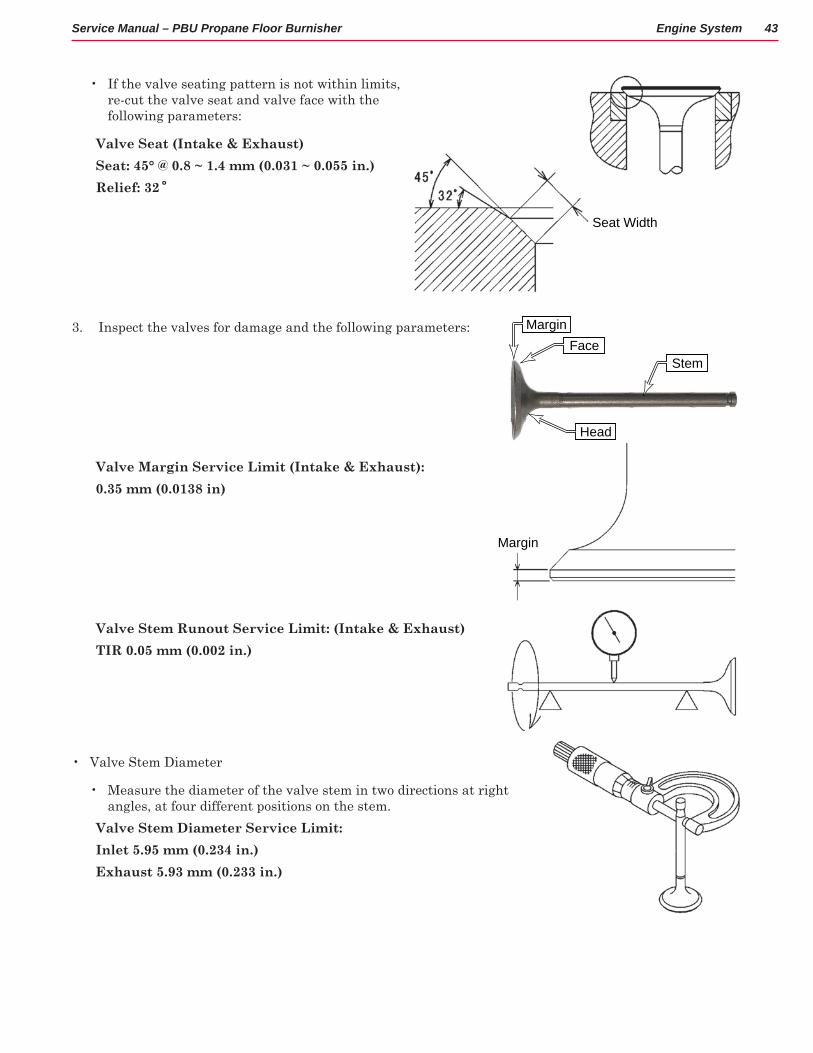
• If the valve seating pattern is not within limits, re-cut the valve seat and valve face with the following parameters:
Valve Seat (Intake & Exhaust)Seat: 45° @ 0 8 ~ 1 4 mm (0 031 ~ 0 055 in )Relief: 32˚
3 Inspect the valves for damage and the following parameters:
Valve Margin Service Limit (Intake & Exhaust):0 35 mm (0 0138 in)
Valve Stem Runout Service Limit: (Intake & Exhaust)TIR 0 05 mm (0 002 in )
• Valve Stem Diameter
• Measure the diameter of the valve stem in two directions at right angles, at four different positions on the stem
Valve Stem Diameter Service Limit:Inlet 5 95 mm (0 234 in )Exhaust 5 93 mm (0 233 in )
Seat Width
Stem
MarginFace
Head
Margin

Engine System 44Service Manual – PBU Propane Floor Burnisher
Valve Guide Inside Diameter Service Limit (Intake & Exhaust):Inlet, Exhaust 6 08 mm (0 239 in )
Valve Spring Free Length Service Limit:Inlet, Exhaust 31 0 mm (1 22 in )
Cylinder Head Replacement
The cylinder head replacement procedure is generally the reverse of the disassembly procedures Use the following notes and interjections while reversing the disassembly steps
1 Reverse the steps for Valve Removal described on page 42
2 Make sure both head and cylinder mating surfaces are clean, and place a new head gasket on the cylinder
3 Double check to make sure no debris has fallen into the cylinder It is best to raise the piston to top-dead-center (which will also be needed for replacing the rocker arms later)
4 Without disturbing the gasket, place the head on the cylinder, and install the 5 head bolts finger-tight only.
5 Begin tightening the head bolts in the crossing pattern shown, and torque them to the specification below. It is critical to properly torque the head bolts to avoid warping the heads
Torque - Cylinder Head Bolts: 27 4 N•m (20 ft•lb)
4
1
2
3
5

Engine System 45Service Manual – PBU Propane Floor Burnisher
6 Make sure the piston is at top-dead-center so that both cams are at their lowest (valves would be closed)
7 Insert the push rods into the lifter valleys and make sure they are seated in the tappet hollows
8 Apply a light film of oil to the rocker eccentric collars.
9 Insert the rocker eccentric collar through the rocker arm, and position the rocker arm in the rocker arm bracket with the push rod in the socket of the rocker arm
10 Place the washer on the rocker arm bolt
11 Insert the rocker arm bolt (J) through the bracket and into the eccentric collar (K) Make sure to align the flat on the bolt with the flat on the collar.
• On the #1 cylinder, insert the bolts with the head pointing up
• On the #2 cylinder, insert the bolts with the head pointing down
12 Install the locking nut (H) on the rocker arm bolt, but leave it slightly loose
13 Set the Valve Clearance described on page 38
14 Replace the Valve Cover described on page 37
15 Continue reassembling the machine, reversing the steps described in Cylinder Head Removal described on page 39
Flat
Collar
Bolt
H
JJ KK

Engine System 46Service Manual – PBU Propane Floor Burnisher
Engine Specifications Item SpecificationType of Engine Forced air-cooled, vertical shaft, OHV, 4-stroke gasoline engineCylinder Layout 90 V-TwinBore × Stroke 73 mm × 72 mm (2.87 in. × 2.84 in.)Piston Displacement 603 cm³ (36.8 cu in.)Direction of Rotation Counterclockwise facing the PTO shaftCompression Release Automatic compression releaseLow Idle Speed 1800 - 2000 RPMHigh Idle Speed 3,400 -3,450 rpm (21 in)
3,450 - 3,550 rpm (27 in)Ignition System Transistorized-flywheel magnetoRFI Per Canada and U.S.A. requirementsStarting System Electric starterCharging System 12 V - 15 amps with regulatorSpark Plug NGK BPR4ESCarburetor 3-hole LP fuel tube, single barrelFuel Pump None Air Cleaner Dual stage element, dry typeGovernor Flyweight all speed governorLubrication System Pressure feed by positive displacement pumpOil Type 30HD or 10W30, API rating SJ or higherOil Filter Cartridge type full flow filterOil Capacity (when engine is completely dry)
2.0 L (2.1 US qt)
Cooling System Forced air cooling by fanDimensions (L × W × H ) 486 mm × 429 mm × 362 mm (19.1 in. × 16.9 in. × 14.3 in.)Dry Weight (without muffler) 36.7 kg (80.9 lb)Specifications are subject to change without notice.
Item Service LimitCylinder Head: Cylinder Compression (MIN) 483 kPa (70 psi) @ Engine Oil Temperature 50 ~ 60°C (122 ~ 144°F),
Cranking Speed 500 rpm/5 Seconds Cylinder Head Warp 0.05 mm (0.002 in.)Valves:Valve Head Thickness: Intake, Exhaust
0.35 mm (0.0138 in.)
Valve Stem Runout: Intake, Exhaust
TIR 0.05 mm (0.002 in.)
Valve Stem Diameter Intake 5.95 mm (0.234 in.) Exhaust 5.93 mm (0.233 in.)Valve Guide Inside Diameter: Intake, Exhaust 6.08 mm (0.239 in.)

Engine System 47Service Manual – PBU Propane Floor Burnisher
Item Service LimitValve Spring Free Length: Intake, Exhaust 31.0 mm (1.22 in.)Rocker Arm Push Rod Runout: Intake, Exhaust TIR 0.5 mm (0.02 in.)Rocker Shaft Outside Diameter: Intake, Exhaust 10.91 mm (0.430 in.)Rocker Arm Inside Diameter: Intake, Exhaust 11.13 mm (0.438 in.)Cylinder, Piston:Piston Diameter 72.79 mm (2.866 in.)Piston Ring/Groove Clearance: Top 0.12 mm (0.0047 in.) Second 0.12 mm (0.0047 in.) Piston Ring Thickness: Top 1.1 mm (0.043 in.) Second 1.1 mm (0.043 in.)Piston Ring End Gap: Top 0.7 mm (0.028 in.) Second 0.9 mm (0.035 in.) Oil 1.05 mm (0.041 in.)Piston Pin Outside Diameter 15.96 mm (0.628 in.)Piston Pin Hole Inside Diameter 16.08 mm (0.633 in.)Connecting Rod Small End Inside Diameter
16.05 mm (0.632 in.)
Cylinder Inside Diameter: Standard Cylinder 73.10 mm (2.878 in.) 0.50 mm Oversize Cylinder 73.60 mm (2.898 in.)Cylinder Inside Diameter Out Round: 0.05 mm (0.002 in.)Valve Clearance: Intake, Exhaust 0.10 ~ 0.15 mm (0.004 ~ 0.006 in.)Valve Seating Surface Angle: Intake, Exhaust 45°Valve Seating Surface Width: Intake 0.8 ~ 1.4 mm (0.031 ~ 0.055 in.) Exhaust 0.8 ~ 1.4 mm (0.031 ~ 0.055 in.)Valves Guide Inside Diameter: Intake, Exhaust 6.000 ~ 6.012 mm (0.2362 ~ 0.2367 in.)Cylinder Inside Diameter: Standard Cylinder 72.98 ~ 73.00 mm (2.873 ~ 2.874 in.) 0.50 mm Oversize Cylinder 73.48 ~ 73.50 mm (2.893 ~ 2894 in.)

Engine System 48Service Manual – PBU Propane Floor Burnisher
Special Tools
Fuel Mixture Kit
The fuel mixture kit contains an oxygen sensor for machines not equipped with the CarbGard system It also contains an oxygen sensor tab for systems that are equipped with CarbGard The volt meter has a special probe to connect to the oxygen sensor tap
Tachometer
Volt Meter Probes
O2 Sensor
O2 Sensor Tap
Volt Meter
Exhaust Analyzer
The exhaust analyzer may be used in place of the fuel mixture kit to adjust the fuel mixture based on carbon monoxide values