pbs - the standards and vehicle … transport commission pbs scheme – the standards and vehicle...
TRANSCRIPT
PERFORMANCE BASED STANDARDS SCHEME
THE STANDARDS AND VEHICLE ASSESSMENT RULES
as at 10 November 2008 (incorporating all amendments consented to by the ATC
up to that date)
Prepared byNational Transport Commission
Performance-Based Standards Scheme – the Standards and Vehicle Assessment Rulesas at 10 November 2008 (incorporating all amendments consented to by the ATC up to the date)
National Heavy Vehicle Regulator
National Transport Commission PBS Scheme – The Standards and Vehicle Assessment Rules
These Rules were made by the National Transport Commission on 30 July 2007, and were approved by the Australian Transport Council on 3 October 2007. This version of the Rules includes amendments that were consented to by the Australian Transport Council on 7 November 2008. ISBN: (TO BE ALLOCATED)
CONTENTS
PART 1 – INTRODUCTORY MATTERS ....................................................................1 1. Purpose of these Rules ..............................................................................................1 2. The Standards to be met ............................................................................................1 3. Exempt prescriptive provisions ...................................................................................1
PART 2 – RULES FOR ASSESSORS........................................................................2 Division 1 – General duty and overview ............................................................................2 4. General duty ...............................................................................................................2 5. Overview of the assessment process .........................................................................2 6. Non-complying vehicle not to be certified ...................................................................3 Division 2 – Modelling and testing procedures ..................................................................3 7. [Reserved] ..................................................................................................................3 8. Assessment procedures for safety standards.............................................................3 9. Required vehicle physical characteristics must be recorded ......................................3 10. Specific requirements concerning the recording of vehicle physical
characteristics.............................................................................................................3 11. Parameter sensitivity testing.......................................................................................4 12. General requirements .................................................................................................4 13. Sensitivity testing of vehicle design features ..............................................................5 14. Sensitivity testing of vehicle operating factors ............................................................5 15. How risk sensitive parameters are to be ranked.........................................................6 17. Certifying compliance with individual standards .........................................................7 18. Certifying a vehicle design/vehicle – primary assessors.............................................7 18A Certifying an alternatively complying vehicle design/vehicle – primary
assessors....................................................................................................................7 19. General requirements concerning completion of certificates......................................8 20. Retention of documents..............................................................................................8
PART 3 – AMENDMENT OF THESE RULES ............................................................8 21. Amendment of these Rules ........................................................................................8
PART 4 – INTERPRETATIVE MATTERS AND REFERENCES ................................9 22. Definitions of general terms ........................................................................................9 23. Reference provisions ................................................................................................10 24. Technical terms ........................................................................................................10 25. Diagrams ..................................................................................................................11 26. Notes ........................................................................................................................11 27. Examples ..................................................................................................................11 28. References to documents.........................................................................................11
APPENDIX A: THE INFRASTRUCTURE STANDARDS..........................................13
APPENDIX B: [RESERVED] ....................................................................................19
APPENDIX C: THE SAFETY STANDARDS.............................................................21
APPENDIX D: [RESERVED] ....................................................................................71
APPENDIX E: ASSESSING SAFETY STANDARDS BY NUMERICAL MODELLING ......................................................................................................73
APPENDIX F: ASSESSING SAFETY STANDARDS BY PRACTICAL TESTING ..........................................................................................................101
APPENDIX H – RISK SENSITIVE PARAMETERS RELATED TO VEHICLE DESIGN FEATURES .......................................................................149

APPENDIX J – INFORMATION AND RECOMMENDATIONS CONCERNING VEHICLE OPERATING CONDITIONS....................................161
APPENDIX K - CERTIFICATE THAT A DESIGN/VEHICLE MEETS ALL THE PERFORMANCE BASED STANDARDS .................................................163
APPENDIX L - CERTIFICATE THAT A DESIGN/VEHICLE MEETS ONE OR MORE SPECIFIC PERFORMANCE BASED STANDARDS......................167
APPENDIX M - CERTIFICATE FOR A DESIGN/VEHICLE THAT DOES NOT MEET ALL THE PERFORMANCE BASED STANDARDS......................167
LIST OF TABLES
Table 1. Ranking of risk sensitive parameters ...........................................................6 Table 2. Maximum gross mass permitted with one or two driving axles...............15 Table 3. Safety Standards...........................................................................................21 Table 4. Startability performance levels....................................................................22 Table 5. Gradeability - Part (a) Maintain Motion performance levels......................25 Table 6. Gradeability - Part (b) Maintain Speed performance levels ......................26 Table 7. Acceleration capability performance levels ...............................................27 Table 8. Network classification by vehicle length ....................................................29 Table 9. Tracking ability performance levels ............................................................32 Table 10. Low speed swept path performance levels ................................................37 Table 11. Frontal swing performance levels ...............................................................41 Table 12. Maximum difference of frontal swing path performance levels ...............44 Table 13. Difference of maximum frontal swing out for performance levels...........45 Table 14. Tail swing performance levels .....................................................................47 Table 15. Steer tyre friction demand performance levels..........................................50 Table 16. Static rollover threshold performance levels .............................................53 Table 17. Rearward amplification performance levels...............................................57 Table 18. High speed transient offtracking performance levels ...............................63 Table 19. Yaw damping performance levels ...............................................................66 Table 20. Deceleration levels for vehicles participating in the Scheme...................68 Table 21. Numerical Modelling - Safety standards references..................................73 Table 22. General application information ..................................................................97 Table 23. Vehicle dimensions.......................................................................................97 Table 24. Mass properties.............................................................................................97 Table 25. Suspensions..................................................................................................98 Table 26. Tyres...............................................................................................................98 Table 27. Chassis properties (flexible) ........................................................................98 Table 28. Powertrain......................................................................................................98 Table 29. Standards assessed with models described in Tables 30 to 34...............98 Table 30. Suspension vertical spring element............................................................99 Table 31. Suspension spring elements (roll) ..............................................................99 Table 32. Suspension damping elements (roll) ..........................................................99 Table 33. Suspension other features...........................................................................99 Table 34. Tyres...............................................................................................................99

Table 35. Numerical modelling results ......................................................................100 Table 36. Practical testing - Safety standards references .......................................101 Table 37. Tracking ability instrumentation requirements ........................................106 Table 38. Low speed swept path instrumentation requirements ............................108 Table 39. Frontal swing instrumentation requirements ...........................................109 Table 40. Tail swing instrumentation requirements .................................................111 Table 41. Steer tyre friction demand instrumentation requirements ......................113 Table 42. General application information ................................................................133 Table 43. Driver details................................................................................................133 Table 44. Prime mover specification..........................................................................134 Table 45. Transducer location ....................................................................................134 Table 46. Vehicle unit details ......................................................................................135 Table 47. Vehicle unit dimension details ...................................................................135 Table 48. Axle group mass details .............................................................................136 Table 49. Tyres .............................................................................................................136 Table 50. Test conditions ............................................................................................137 Table 51. Weather conditions .....................................................................................137 Table 52. Testing personnel........................................................................................137 Table 53. Vehicle safety check ...................................................................................138 Table 54. Test results ..................................................................................................138 Table 55. Comments ....................................................................................................140
LIST OF FIGURES
Figure 1. Perspective view illustration of front and rear outside-corner path trajectories and swept width in the tracking ability on a straight path test..........................................................................................................31
Figure 2. Underside perspective view illustration showing typical characteristics of the path trajectories and offsets due to cross slope. ..............................................................................................................31
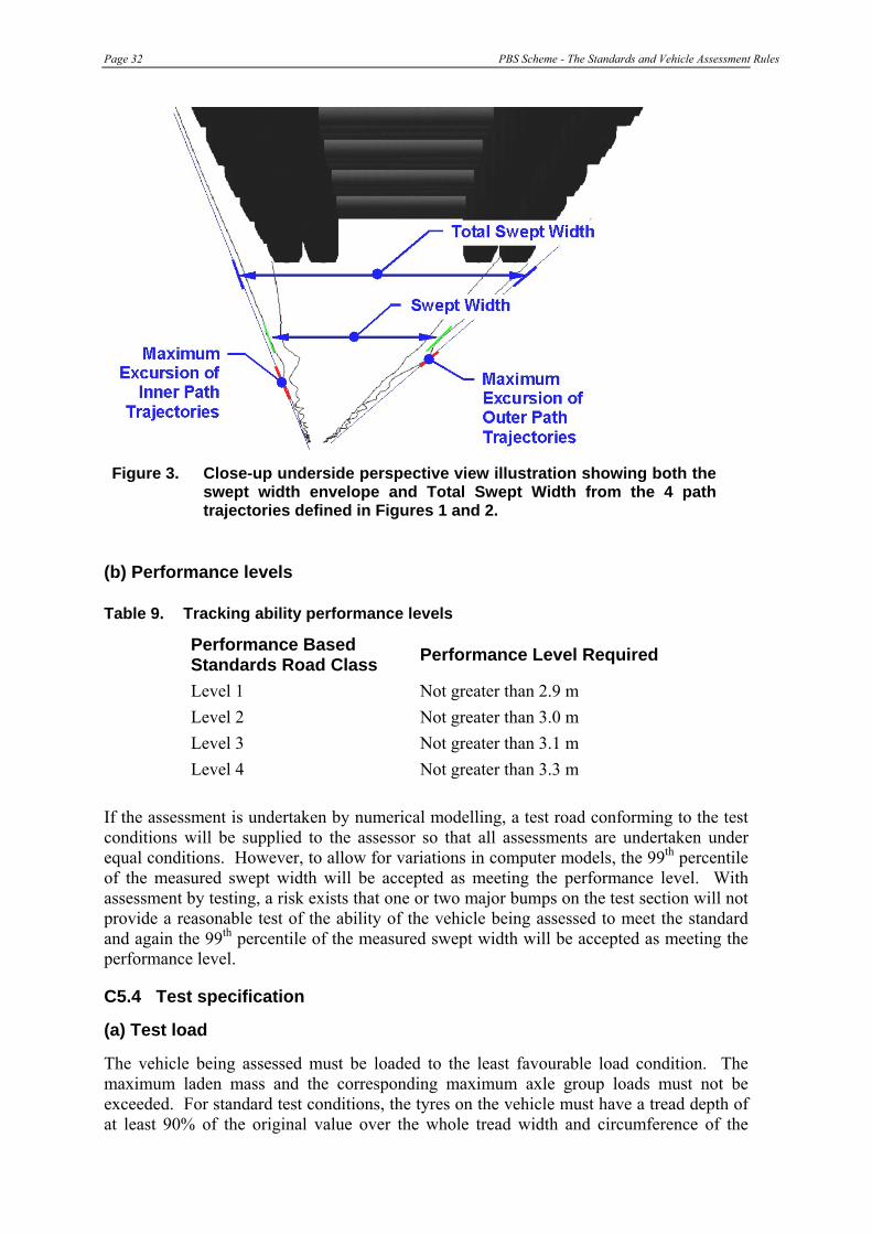
Figure 3. Close-up underside perspective view illustration showing both the swept width envelope and Total Swept Width from the 4 path trajectories defined in Figures 1 and 2........................................................32
Figure 4. Perspective view illustration of vehicle partway through the Performance Based Standards low-speed turn showing path trajectories. ....................................................................................................36
Figure 5. Plan view illustration of path trajectories that define the vehicle’s swept path in the Performance Based Standards low-speed turn. ..........36
Figure 6. Plan view illustration of Maximum Width of Swept Path, SPWmax. Note that the line perpendicular to both path trajectories (shown dotted in the illustration) does not necessarily pass through the turn centre......................................................................................................37
Figure 7. Illustration of outside wheel reference point. .............................................38 Figure 8. Illustration of path trajectories in the Performance Based
Standards low-speed turn of Part A of the frontal swing performance measure. For this measure the innermost path is the path followed by the outside front wheel....................................................40
Figure 9. Perspective view illustration of path trajectories partway through the Performance Based Standards low-speed turn for Parts B and C of frontal swing MoD and DoM performance measures. .......................42
Figure 10. Perspective view illustration of Parts B and C of the frontal swing MoD and DoM performance measures looking along the exit tangent during the final stages of the low-speed turn. .............................42
Figure 11. Further detail on the Parts B and C frontal swing DoM and MoD performance measures. Note that the vertical (X) axis scale is exaggerated. ..................................................................................................43
Figure 12. A contrasting example to the one shown in Figure 11 of the Parts B and C frontal swing DoM and MoD performance measures. Note that the vertical (X) axis scale is exaggerated............................................43
Figure 13. Illustration of tail swing performance measure at commencement of the Performance Based Standards low-speed turn. .............................47
Figure 14. SAE Tyre Axis System (Society of Automotive Engineers, 1976) ............49 Figure 15. Typical axle lift-off sequence and rollover threshold for a prime
mover and semi-trailer combination. ..........................................................52 Figure 16. Side and plan view illustration of 2 roll-coupled trailers showing
sprung masses, sprung mass centre of gravity heights, and lateral accelerations, AY. .........................................................................................54
Figure 17. Illustration of rearmost roll-coupled units (rrcu) in 3 example vehicles; a prime mover and semi-trailer combination, an A-triple, an AAB-quad and a Double B-Triple. ..........................................................58
Figure 18. Perspective view illustration of final stages of the single lane change manoeuvre showing overshoot dimension in the ground plane of the rear axle centre for high-speed transient offtracking...........62
Figure 19. Illustration of high-speed transient offtracking overshoot and undershoot scenarios from Society of Automotive Engineers (1993a)............................................................................................................62
Figure 20. Determination of amplitudes for damping ratio calculation. ....................65 Figure 21. Illustration of roll steer effect on a beam axle (from Fancher et al,
1986). ..............................................................................................................83 Figure 22. Side force characteristics of an 11R22.5 size truck tyre showing
the influence of tyre vertical load. ...............................................................84 Figure 23. Aligning moment characteristics of an 11R22.5 size truck tyre
showing the influence of tyre vertical load. ...............................................85 Figure 24. Exact form of the pulse steer input given by equation E4a. .....................90 Figure 25. Idealised brake forces acting on a semi-trailer. .........................................92

PBS Scheme - The Standards and Vehicle Assessment Rules Page 1
PART 1 – INTRODUCTORY MATTERS
1. Purpose of these Rules
The purpose of these Rules is to specify –
(a) the Performance Based Standards that must be met for a vehicle to be eligible to participate in the Performance Based Standards Scheme; and
(b) the methods of assessment and the procedures for assessment that must be used by assessors to determine if those Standards are met in any particular case.
2. The Standards to be met
(1) To be eligible to participate in the Scheme, a vehicle must meet –
(a) all of the infrastructure standards set out in Appendix A; and
(b) all of the safety standards set out in Appendix C.
(2) In general, a vehicle meets those standards for the purposes of the Scheme if either –
(a) the design of the vehicle is assessed in accordance with these Rules as having a high probability of meeting all of those standards, and it is established that the vehicle was built according to that design; or
(b) the vehicle is assessed in accordance with these Rules as meeting all of those standards.
3. Exempt prescriptive provisions
(1) If a vehicle is eligible to participate in the Scheme, it may be exempted from –
(a) any of the following provisions of the Australian Vehicle Standards that are incompatible with its design –
(i) clause 66 (Width); (ii) clause 67 (Length of single motor vehicles); (iii) clause 68 (Length of single trailers); (iv) clause 69 (Length of combinations); (v) clause 70 (except subclause (3)(a))(Rear overhang); (vi) clause 71 (Trailer drawbar length); (vii) clause 72 (Height); (viii) clauses 169 (b) and (c) (Attachment of couplings and drawbar eyes
on long road trains); (ix) clause 171 (Tow coupling overhang on long road trains); and

Page 2 PBS Scheme - The Standards and Vehicle Assessment Rules
(b) any of the following provisions of the Australian Design Rules that are incompatible with its design –
(i) Rule 43, clause 6.1 (Length); (ii) Rule 43, clause 6.2 (Rear overhang)(other than clause 6.2.1); (iii) Rule 43, clause 6.3 (Height); (iv) Rule 43, clause 6.5 (Width); (v) Rule 43, clause 9.4 (Retractable axles); (vi) Rule 43, clause 9.5 (Retractable axles); (vii) Rule 62, clause 5.3 (Tow coupling overhang); (viii) Rule 63, clause 63.5.1 (Tow coupling location).
(2) Despite subrule (1)(b)(ii), if a trailer to which clause 6.2.1 of Rule 43 applies is
eligible to participate in the Scheme and has a rear overhang of more than 3.7 metres, it may be exempted from that clause if it otherwise complies with that clause.
PART 2 – RULES FOR ASSESSORS
Division 1 – General duty and overview
4. General duty
An assessor assessing a vehicle design or a vehicle for the purposes of the Scheme must comply with all of the requirements set out in these Rules.
5. Overview of the assessment process
(1) To conduct an assessment of a vehicle design or a vehicle for the purposes of the Scheme, the assessor must assess the design or vehicle against the requirements of the standards by means of numerical modelling or testing conducted in accordance with Division 2.
(2) If the assessor is of the opinion that the design or vehicle will, or does, meet the standard or standards in respect of which the modelling or testing was conducted to the extent required by these Rules, he or she must –
(a) identify and record the vehicle physical characteristics of the design or vehicle in accordance with Division 3; and
(b) conduct, if thought necessary, one or more risk sensitivity analyses of the design or vehicle in accordance with Division 4; and
(c) consider whether to recommend any national operating conditions in respect of the design or vehicle in accordance with Division 5; and
(d) determine from which of the prescriptive requirements listed in rule 3 the design or vehicle will need exemption; and

PBS Scheme - The Standards and Vehicle Assessment Rules Page 3
(e) issue any certificate required by Division 6.
6. Non-complying vehicle not to be certified
If the assessor determines that a vehicle design or vehicle will not, or does not, meet one or more of the standards to the extent required by these Rules, and is not likely to be eligible for approval under rule 33A or 33B of the Performance Based Standards Scheme: Review Panel Business Rules, he or she must not issue a certificate in relation to the vehicle.
Division 2 – Modelling and testing procedures
7. [Reserved]
8. Assessment procedures for safety standards
(1) To assess a vehicle design or a vehicle against a safety standard specified in Appendix C, the assessor must carry out modelling or testing in accordance with any requirements for Test Specification in Appendix C, unless another Appendix expressly provides for another specification, and –
(a) if the assessment is undertaken by numerical modelling, the procedures in Appendix E must also be followed;
(b) if the assessment is undertaken by testing, the procedures in Appendix F must also be followed.
(2) If a vehicle is to be field tested and the assessor is responsible for organising that testing, he or she must ensure that a site manager is on site before any testing starts, and that the site manager remains on site during the whole of the field testing programme. The assessor may also be the site manager.
Division 3 – Vehicle physical characteristics
9. Required vehicle physical characteristics must be recorded
(1) As part of the assessment process, the assessor must complete the Vehicle Certification Information (Appendix G) for the vehicle design.
(2) The assessor must ensure that the Vehicle Certification Information sets out a complete description of the vehicle physical characteristics that a vehicle built to the design must have to enable the vehicle to meet the standards.
(3) The assessor may refer, in an entry in the Vehicle Certification Information for a design, to drawings or other information, provided the link is clearly identifiable, and the drawings or other information are attached to the Information.
10. Specific requirements concerning the recording of vehicle physical characteristics
(1) The assessor must comply with the requirements of this rule in completing the Vehicle Certification Information (Appendix G).
Page 4 PBS Scheme - The Standards and Vehicle Assessment Rules
(2) For each trailer, semi-trailer or dolly proposed in a design, the assessor must identify the vehicle physical characteristics for each separate vehicle unit, and must also identify the position of the vehicle unit in the proposed combination.
(3) The assessor must specify all dimensions as a maximum, a minimum, or as a maximum and a minimum (i.e. a range).
(4) The assessor must specify the vehicle physical characteristics in a way that allows the characteristics to be checked using one or more of the following methods –
(a) physically checking the vehicle by straightforward measurements taken by a certifier;
(b) checking by a simple visual inspection of components by a certifier (for instance, this could involve confirming the make, model and serial number of specific components such as the chassis, engine or transmission, or of entire suspension assemblies or individual suspension components (shock absorbers, airbags, springs, and the like), tyres, and other features or components that are considered to be risk sensitive);
(c) checking by a certifier by sighting written documents from service providers (these could include other assessors not involved with the specific assessment), manufacturers or component suppliers/testers.
(5) If vehicle physical characteristics cannot be specified using one or more of the methods in subrule (4), the assessor must specify a reasonable way for a certifier to check the characteristic.
Division 4 –Sensitivity testing
11. Parameter sensitivity testing
(1) This Division applies if it appears to the assessor that, in respect of either a design feature or an operating factor, there is a significant risk that a vehicle built to the design being assessed by the assessor may not perform as designed as a result of off-baseline variations in the characteristics of a relevant critical component, sub-assembly or load.
(2) The assessor must undertake a parameter sensitivity analysis in relation to the design’s compliance with the standard or standards in respect of which the risk arises with a view to determining whether or not it may be necessary to take steps to control the risk (such as by the imposition of one or more operating conditions).
12. General requirements
(1) If a parameter sensitivity analysis is undertaken, the assessor must list risk sensitive parameters and the off-baseline variation used (%) in the same form as is shown in Appendix H or Appendix I, as the case may be.
(2) If there is more than one trailer, semi-trailer or dolly proposed in a design, the assessor must identify the relevant risk sensitive parameters for each separate vehicle unit, and must also take into account the position of each vehicle unit in the proposed combination.

PBS Scheme - The Standards and Vehicle Assessment Rules Page 5
13. Sensitivity testing of vehicle design features
(1) This rule applies if an assessment of risk sensitive parameters that relate to vehicle design features is undertaken.
(2) The risk sensitive parameters that should be considered in an initial sensitivity analysis for particular safety standards are set out in Appendix H. The parameters listed are not intended to be all-inclusive, and there may be other parameters that the assessor chooses to consider in response to any unique features of a design. By the same token, nothing in this Division requires the assessor to conduct a sensitivity analysis for a parameter in respect of a particular application if the assessor considers that the parameter is not significant (in a practical sense) to that application.
(3) The baseline figure the assessor must use in conducting a sensitivity analysis in respect of a standard, or an aspect of a standard, is –
(a) in the case of numerical modelling, the performance achieved in respect of that standard, or aspect, as recorded in Table 36; or
(b) in the case of physical testing, the result or reference in respect of that standard, or aspect, as recorded in Table 55.
(4) A sensitivity analysis must consider off-baseline variations in parameter values caused by –
(a) the following known variations –
(i) expected variations due to manufacturing tolerances;
(ii) expected variations in the performance characteristics of like components sourced from the same or different suppliers;
(iii) expected in-service variations due to normal wear and tear; and
(b) other known variations.
(5) If variations in parameter values are not known or cannot be reasonably estimated, they are to be taken to be ±20% of the baseline values.
(6) The assessor must recalculate the performance of the vehicle design with respect to the standard using the maximum value of the off-baseline variation range, and then must repeat the calculation using the minimum value of the off-baseline variation range.
(7) The assessor must identify a parameter as a risk sensitive parameter if he or she determines that an off-baseline variation produces a change in the value of the standard outcome of not less than 2.0%.
14. Sensitivity testing of vehicle operating factors
(1) This rule applies if an assessment of risk sensitive parameters that relate to vehicle operating factors is undertaken.
(2) The risk sensitive parameters that should be considered in an initial sensitivity analysis for particular safety standards are set out Appendix I. The parameters

Page 6 PBS Scheme - The Standards and Vehicle Assessment Rules
listed are not intended to be all-inclusive, and there may be other parameters that the assessor chooses to consider.
(3) The assessment must be carried out in a manner similar to that required for vehicle design features in rule 13.
(4) The sensitivity analysis must consider the likely largest in-service variations, and where variations are unknown, then the variation is to be taken to be ±20% of the baseline values.
15. How risk sensitive parameters are to be ranked
(1) Risk sensitive parameters must be ranked as specified in Table 1.
Table 1. Ranking of risk sensitive parameters
Ranking Percentage change in numerical value of safety standard
1 20.0% or more
2 2.0% or more but less than 20.0%
(2) The initial rankings shown in Appendix H and in Appendix I are indicative only. Actual rankings can vary from one vehicle design to another and will depend on specific design features, operating conditions and the commodity transported.
Division 5 – Recommendations on conditions 16. Assessor must consider whether national operating conditions
desirable
(1) After conducting any testing required by Division 4, the assessor must –
(a) complete items 1 – 3 of Appendix J; and
(b) in the light of that information and the results of the testing, consider whether to recommend that the vehicle, or a vehicle built to the design, assessed by him or her should be made subject to one or more operating conditions once it begins to operate; and
(c) if he or she considers that one or more operating conditions should be imposed, list that condition, or those conditions, in item 5 of Appendix J.
(2) In considering whether to recommend the imposition of operating conditions, the assessor must have regard to the Performance Based Standards: Guidelines for Determining National Operating Conditions, as approved by the Australian Transport Council from time to time.
PBS Scheme - The Standards and Vehicle Assessment Rules Page 7
Division 6 – Certificates of compliance
17. Certifying compliance with individual standards
(1) If an assessor has assessed a vehicle design in relation to a standard and is of the opinion that a vehicle built to that design will meet the standard, he or she must issue a certificate in the form of Appendix L to that effect.
[Subrule (2) was deleted as a consequence of an amendment consented to by the ATC on 7 November 2008.]
(3) If an assessor has assessed a vehicle in relation to a standard and is of the opinion that it meets the standard, he or she must issue a certificate in the form of Appendix L to that effect.
(4) Despite subrules (1) and (3), an assessor need not issue a certificate in the circumstances described in those sub-rules if the person who commissioned the assessment asks him or her not to issue the certificate.
(4) In issuing a certificate under subrule (1) or (3), the assessor must ensure that the certificate includes all the information required by Appendix L, and that there is attached to the certificate any attachment required by Appendix L.
(5) The assessor may issue a certificate in respect of more than one standard if he or she is accredited to conduct assessments on the additional standard or standards, but only a primary assessor may issue a certificate in relation to all the standards.
18. Certifying a vehicle design/vehicle – primary assessors
(1) If a primary assessor has assessed a vehicle design and is of the opinion that a vehicle built to that design will meet all of the standards, he or she must issue a certificate in the form of Appendix K to that effect.
[Subrule (2) was deleted as a consequence of an amendment consented to by the ATC on 7 November 2008.]
(3) If a primary assessor has assessed a vehicle and is of the opinion that it meets all of the standards, he or she must issue a certificate in the form of Appendix K to that effect.
(4) Despite sub-rules (1) and (3), a primary assessor need not issue a certificate in the circumstances described in those sub-rules if the person who commissioned the assessment asks him or her not to issue the certificate.
18A. Certifying an alternatively complying vehicle design/vehicle – primary assessors
(1) If a primary assessor has assessed a vehicle design and is of the opinion that a vehicle built to that design will not meet all of the standards, but that it is likely that the design is eligible for approval under rule 33A or 33B of the Performance Based Standards Scheme: Review Panel Business Rules, he or she must issue a certificate in the form of Appendix M to that effect.
(2) If a primary assessor has assessed a vehicle and is of the opinion that it does not meet all of the standards, but that it is likely that it is eligible for approval under

Page 8 PBS Scheme - The Standards and Vehicle Assessment Rules
rule 33A or 33B of the Performance Based Standards Scheme: Review Panel Business Rules, he or she must issue a certificate in the form of Appendix M to that effect.
(3) Despite sub-rules (1) and (2), a primary assessor need not issue a certificate in the circumstances described in those sub-rules if the person who commissioned the assessment asks him or her not to issue the certificate.
19. General requirements concerning completion of certificates
(1) In issuing a certificate, the assessor must comply with any procedures that have been specified by the Panel.
(2) Before signing a certificate, the assessor must ensure that all the information required by the certificate form has been inserted into, or is attached to, the certificate.
20. Retention of documents
(1) The assessor must retain for at least 5 years –
(a) all documents relating to numerical modelling recorded by him or her in accordance with Appendix E; and
(b) all documents relating to field testing recorded by him or her in accordance with Appendix F.
(2) The assessor must retain and maintain any other documents relating to assessments conducted by him or her that he or she is required by the Panel to keep and maintain, and must do so in accordance with the directions of the Panel.
(3) The assessor must make available to the Panel, or a representative of the Panel, on request any document that he or she is required to retain under this rule.
PART 3 – AMENDMENT OF THESE RULES
21. Amendment of these Rules
(1) These Rules may only be amended by the National Transport Commission –
(a) with the consent of the Australian Transport Council; or
(b) in the case of an amendment that is of an administrative or non-controversial nature, with the unanimous consent of the Transport Agency Chief Executives.
(2) A reference in any document to these Rules as approved by the ATC from time to time is to be read as including any amendments consented to by TACE under subrule (1)(b).
PBS Scheme - The Standards and Vehicle Assessment Rules Page 9
PART 4 – INTERPRETATIVE MATTERS AND REFERENCES
22. Definitions of general terms
In these Rules, unless the contrary intention appears –
assessor means a person accredited to assess vehicle designs and vehicles for the purposes of the Scheme;
certificate means the certificate set out in Appendix K or L;
combination vehicle means a group of vehicles consisting of a motor vehicle connected to 1 or more vehicles;
hauling unit means the motor vehicle that provides the primary means of motive power for a combination vehicle;
infrastructure standard means a standard set out in Appendix A;
least favourable load condition means the loading condition that will produce the worst case result, either under the maximum laden mass, in the unladen condition or in some other loading condition, including consideration of asymmetry of loading if the vehicle is designed to operate with an asymmetric load and partial loading if the vehicle is a road tanker;
maximum axle or axle group mass means the maximum mass on each axle or axle group at which a vehicle would be authorised to operate if it were to be permitted to operate under the Scheme;
maximum laden mass means the maximum gross mass at which a potential vehicle would be authorised to operate if it were to be permitted to operate under the Scheme;
Network Classification Guidelines means the Performance Based Standards Scheme: Network Classification Guidelines, as approved by the Australian Transport Council from time to time;
Performance Based Standards Road Classification Level means the level of access to the road network as defined in the Network Classification Guidelines;
performance level means the performance level specified in relation to a particular standard in Appendix A or C;
primary assessor means an assessor who takes primary responsibility for the assessment of a vehicle design, or vehicle, and who is accredited to issue a certificate in the form of Appendix G;
safety standard means a standard set out in Appendix C;
Scheme means the Performance Based Standards Scheme;
site manager means the person responsible for the organisation of the field testing on the test site and for conducting the field testing in a safe manner;
standard means an infrastructure standard or a safety standard;
trailing unit means a unit generally without motive power that is towed or meant to be towed but does not include a hauling unit that is being towed;

Page 10 PBS Scheme - The Standards and Vehicle Assessment Rules
vehicle includes the equipment fitted to, or forming part of, the vehicle;
vehicle physical characteristic means –
(a) a dimension; or
(b) a component of a vehicle including but not limited to its tyres, suspension, engine, couplings, brakes or control system, including an emissions control system;
vehicle unit means any rigid part of a combination vehicle.
23. Reference provisions
(1) A reference in these Rules to a vehicle is to be read as including a reference to a combination vehicle, unless the contrary intention appears.
(2) A reference in the appendices to a vehicle is to be read as including a reference to a vehicle design if the context requires or permits.
24. Technical terms
(1) The reference Society of Automotive Engineers (1976) must be used as the source of technical terms used in the Appendices as they relate to vehicle dynamics terminology.
(2) It is possible that the exact term used in the appendices is not the same as in the reference, but if the term being defined has the same general meaning as a term in the reference, the definition in the reference must be used.
(3) Any dispute about the definition of a technical term is to be determined by the Panel.
(4) Unless there is a conflict with a term defined in the reference, the following definitions of other technical terms apply:
auxiliary brakes mean engine brakes, exhaust brakes and retarders but not the service brakes for the vehicle;
crossfall means the slope of a road surface such that there is a difference in elevation of the left and right wheel paths;
International Roughness Index means the measure of road roughness as defined by the World Bank (also described as IRI);
percentage grade means 100 times the change-in-height divided by the (horizontal) distance over which the height change occurs;
roll-coupled means the joining of vehicle units such that roll motion is transferred from one vehicle unit to the next vehicle unit either ahead or behind, usually by means of a fifth wheel;
roll-coupled unit means a series of vehicle units that are roll-coupled;
swept width means the width of traffic lane required to accommodate all lateral motions of the tyres of a vehicle during straight-line travel;
PBS Scheme - The Standards and Vehicle Assessment Rules Page 11
test length means the section of pavement between the start of testing and the end or finish mark used for testing;
upgrade means the slope of a road surface such that elevation increases as a vehicle travels in the forward direction.
25. Diagrams
(1) A diagram in these Rules is part of these Rules.
(2) A diagram of something is an illustrative example of the thing, but does not represent its dimensions or the dimensions of any part of it.
26. Notes
A note in these Rules is part of these Rules.
27. Examples
(1) An example (whether or not in the form of a diagram) in these Rules is part of these Rules.
(2) If these Rules include an example of the operation of a provision of these Rules –
(a) the example is not exhaustive; and
(b) the example may extend the meaning of the provision; and
(c) the example does not limit the meaning of the provision unless the contrary intention appears.
28. References to documents
(1) References used in these Rules are as follows –
(a) Australian Design Rules. Australian Design Rules for Motor Vehicles & Trailers (3rd edition), being national standards for the purposes of the Motor Vehicle Standards Act 1989 (Commonwealth);
(b) Austroads 2004. Heavy vehicle mass – measurement adjustment and breakpoints. Guidelines for the physical measurement of heavy vehicle mass. Stage 1 report. Austroads project RUM.HV.C.035 (Draft). Austroads: Sydney NSW;
(c) ECE R13V9, Annex 13, Appendix 2 Cl. 1.1.4;
(d) International Standards Organisation ISO 14791:2000. Road vehicles – heavy commercial vehicle combinations and articulated buses – lateral stability test methods. ISO, Geneva, Switzerland;
(e) McLean, J.R. and Hoffman, E.R. (1971). Analysis of Drivers’ Control Movements. Human Factors, 13(5), pp407-418. Human Factors and Ergonomics Society, Santa Monica, California;
(f) McLean, J.R. and Hoffman, E.R. (1973). The Effects of Restricted Preview on Driver Steering Control and Performance. Human Factors, 15(4), pp421-430. Human Factors and Ergonomics Society, Santa Monica,
Page 12 PBS Scheme - The Standards and Vehicle Assessment Rules
California;
(g) Sayers M W, Gillespie T D and Paterson W D O, 1986. Guidelines for conducting and calibrating road roughness measurements. World Bank Technical Paper no. 46. World Bank, Washington D.C;
(h) Society of Automotive Engineers (1976). Vehicle Dynamics Terminology. SAE Recommended Practice J670e, Society of Automotive Engineers: Warrendale, PA, United States of America;
(i) Society of Automotive Engineers (1993a). A Test for Evaluating the Rearward Amplification of Multi-Articulated Vehicles. SAE Recommended Practice J 2179. Society of Automotive Engineers: Warrendale, PA, United States of America;
(j) Society of Automotive Engineers (1993b). Steady-state Circular Test Procedure for Trucks and Buses. SAE Recommended Practice J 2181, Society of Automotive Engineers: Warrendale, PA, United States of America;
(k) Society of Automotive Engineers (1998). A Tilt Table Procedure for Measuring the Static Rollover Threshold for Heavy Trucks. SAE Recommended Practice J 2180, Society of Automotive Engineers: Warrendale, PA, United States of America;
(m) Standards Australia AS/NZS 4602:1999 High visibility safety garments. Standards Australia, Homebush, NSW;
(n) Standards Australia AS 1742.3:2002, Manual of uniform traffic control devices, Part 3 – traffic control devices for works on roads. Standards Australia, Homebush, NSW;
(o) Standards Australia AS/NZS 4360:2004, Risk management. Standards Australia, Homebush, NSW;
(p) Tyre and Rim Association of Australia, 2004. Standards Manual. Tyre and Rim Association of Australia: Hawthorn, Vic.
(2) A reference to any of these documents is to be read as a reference to the document as amended from time to time, unless a contrary intention appears.

PBS Scheme - The Standards and Vehicle Assessment Rules Page 13
APPENDIX A: THE INFRASTRUCTURE STANDARDS
A1 PAVEMENT VERTICAL LOADING (INTERIM STANDARD)
A1.1 Purpose and Intent
(a) Purpose
The purpose of the pavement vertical loading standard is to limit the stress on the pavement layers below the surface of the road.
(b) Intent
The basis of the standard is to limit individual axle group1 loads to those that presently apply under:
• General Mass Limits2 (GML);
• Concessional Mass Limits3 (CML); or
• Higher Mass Limits4 (HML).
Total gross mass is not limited by this standard, but may be limited indirectly by the Bridge Loading standard and the safety standards. The Network Classification Guidelines presently limit General Access vehicles to a gross mass of 50 tonnes.
Jurisdictions reserve the right to refuse access to their road network, or to exclude vulnerable assets from a vehicle’s access arrangements, if they have a reasonable concern that the vehicle’s intended operation would cause unacceptable pavement wear, until such time as a pricing regime that fully recovers the pavement wear costs of PBS and other high productivity vehicles is operational.
Whilst a full cost-recovery mechanism is not expected to be available before mid-2008, jurisdictions may consider permitting operators to participate in incremental pricing trials that are programmed to commence in early 2008. In embracing such an approach, the requirements of local governments should be considered.
A1.2 Definition
The axle group loads for a PBS vehicle shall not exceed the maximum permitted on the route/network for commercial5 heavy vehicles (refer to Intent above for detail). Axle group types are limited to present prescriptive configurations1.
A1.3 Requirements
An assessor must state that a proposed vehicle meets the standard and that the vehicle will only use the routes/network for which the specified axle group mass limits apply. 1 As defined in the Australian Design Rules or otherwise permitted by a jurisdiction (e.g. tandem axle group). Note that the listings of exempt prescriptive provisions on page 1 of this document do not provide for exemptions to be sought for axle configuration at this time. 2 As per Table 1 of Schedule 1 of the National Transport Commission (Road Transport Legislation – Mass and Loading Regulations) Regulations 2006. 3 See NTC web site (www.ntc.gov.au). 4 See NTC web site (www.ntc.gov.au). 5 Heavy vehicles other than special purpose vehicles and those operating under indivisible load notices and permits.
Page 14 PBS Scheme - The Standards and Vehicle Assessment Rules
Vehicles operating under CML or HML axle loads are, by default, subject to the operating conditions that are normally applied to prescriptive CML and HML vehicles, such as mass management accreditation and certified road-friendly suspensions (in the case of HML).
A2 PAVEMENT HORIZONTAL LOADING
A2.1 Purpose and intent
(a) Purpose
The purpose of this standard is to regulate road wear by limiting the impact on the surface of road pavements of:
• the horizontal tyre forces of a multi-axle group when turning; and
• the tractive tyre forces of the drive axle or axles when a vehicle participating in the Scheme is starting or climbing an upgrade.
(b) Intent
The horizontal forces imposed on a pavement are the longitudinal tyre forces caused by braking and by the drive axle or axles when a vehicle starts, accelerates or climbs an uphill grade and the lateral or side forces that are generated by multi-axle groups during a turning manoeuvre.
A vehicle’s tractive capability, its axle loads, axle spacing, and its low-speed offtracking influence the horizontal forces. Road-related effects such as horizontal and vertical geometry, grade and surface characteristics (tyre/road friction) also contribute to the horizontal forces that can be generated. The horizontal forces are of a concern in areas where significant turning, traction or braking is expected. However, to be consistent with road safety objectives, the limitation of braking forces is not feasible under this standard.
Traditionally, wear of surfacings has not been treated separately from pavement wear, and has been implicitly assumed to be part of the wear attributed to fourth power Equivalent Standard Axles (ESAs). However, there are growing concerns that the horizontal forces generated by heavy vehicles are causing excessive surface wear for bituminous chip-seal pavements and asphalt pavements. Horizontal forces have a direct influence on pavement wear and are particularly important for bituminous chip-seal pavements in areas of road-train operation.
It is the intention that this standard will eventually be performance-based. However, until further work has been undertaken to develop a suitable performance standard, a prescriptive requirement has been adopted.
A2.2 Definition
The degree to which horizontal forces are applied to the pavement surface, primarily in a low-speed turn, during acceleration and on uphill grades.
A2.3 Requirements
In relation to axle groups:
• for tandem axle groups with an axle spacing of more than 2 metres, at least one axle must be steerable; and
PBS Scheme - The Standards and Vehicle Assessment Rules Page 15
• for axle groups with three or more axles and a spread of greater than 3.2 metres, all axles beyond the 3.2 metre spread must be steerable.
In relation to driving axles:
• all driving axles in a drive axle group must distribute tractive forces, such that the maximum difference in tractive force between any two driving axles in the group is not greater than 10% of the total tractive force delivered by the drive axle group; and
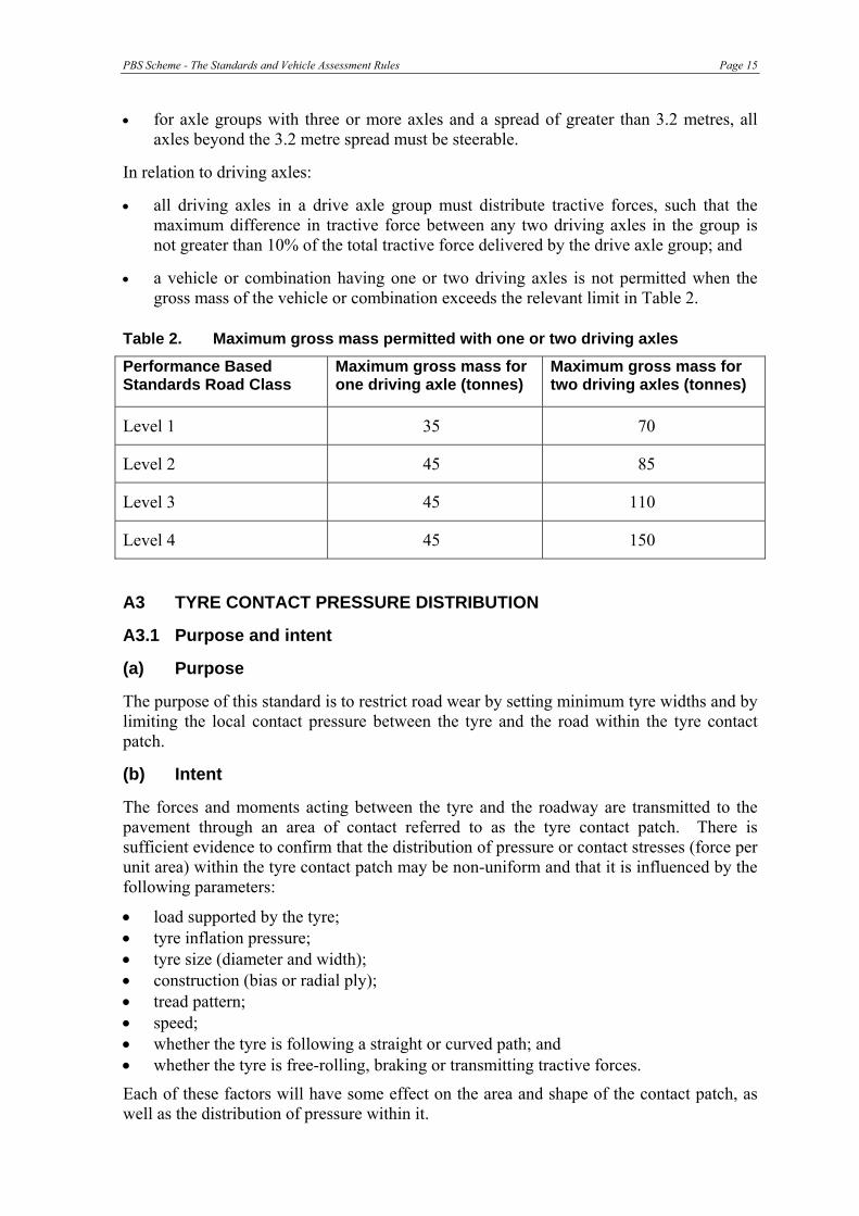
• a vehicle or combination having one or two driving axles is not permitted when the gross mass of the vehicle or combination exceeds the relevant limit in Table 2.
Table 2. Maximum gross mass permitted with one or two driving axles
Performance Based Standards Road Class
Maximum gross mass for one driving axle (tonnes)
Maximum gross mass for two driving axles (tonnes)
Level 1 35 70
Level 2 45 85
Level 3 45 110
Level 4 45 150
A3 TYRE CONTACT PRESSURE DISTRIBUTION
A3.1 Purpose and intent
(a) Purpose
The purpose of this standard is to restrict road wear by setting minimum tyre widths and by limiting the local contact pressure between the tyre and the road within the tyre contact patch.
(b) Intent
The forces and moments acting between the tyre and the roadway are transmitted to the pavement through an area of contact referred to as the tyre contact patch. There is sufficient evidence to confirm that the distribution of pressure or contact stresses (force per unit area) within the tyre contact patch may be non-uniform and that it is influenced by the following parameters:
• load supported by the tyre; • tyre inflation pressure; • tyre size (diameter and width); • construction (bias or radial ply); • tread pattern; • speed; • whether the tyre is following a straight or curved path; and • whether the tyre is free-rolling, braking or transmitting tractive forces.
Each of these factors will have some effect on the area and shape of the contact patch, as well as the distribution of pressure within it.
Page 16 PBS Scheme - The Standards and Vehicle Assessment Rules
Traditional design and evaluation of pavements assumes the vertical (or normal) contact pressure between the tyre and the roadway is uniformly distributed over a contact area that is circular. While this approach may be adequate for relatively thick (>75mm) asphalt surfacing and base layers, it would be highly inaccurate for thinner layers subjected to non-uniform tyre contact stresses (De Beer, 1996a). Further, recent research suggests that the damage to the chip-seal surfacing increases in proportion to the maximum tensile strain raised to the fifth power (Prem et al, 2000); this means that doubling the tensile strain would increase damage by a factor of 32. Horizontal tensile strains resulting from non-uniform contact stress distributions can be up to 100% higher when compared to those from uniform stress distributions, indicating the potential for premature failure (De Beer, 1996a).
Australia’s sealed rural road network consists predominantly of bituminous chip-sealed granular pavements. The performance and wear of these thin pavements is directly influenced by the distribution of pressure within the tyre contact patch and the shape of the patch (i.e. the tyre width).
Until further work can quantify the impacts of tyre patch shape, maximum tyre pressure and tyre pressure differentials, a prescriptive requirement has been adopted.
A3.2 Definition
The minimum tyre width that is allowed, and the maximum pressure and pressure variation that is applied to the road surface by a single-tyre or pair of tyres in a dual tyred set.
A3.3 Requirements
Existing prescriptive requirements relating to minimum tyre width and maximum pressure have been retained and applied to vehicles participating in the Scheme.
A4 BRIDGE LOADING
A4.1 Purpose and Intent
(a) Purpose
To limit the maximum effect on a bridge to that which is acceptable to the bridge owner6.
(b) Intent
The protection of bridges is primarily an infrastructure issue but becomes a safety issue when a bridge component fails or an entire bridge collapses. The bridge loading standard addresses the issue of bridge strength and ensures that a vehicle in the Scheme does not induce effects on bridge structures that exceed accepted limits as specified by the bridge owner.
A4.2 Definition
The effects caused by a vehicle in the Scheme on any bridge on the route/network requested shall be limited by either of the following methods (‘tiers’). Note that each successive tier may allow greater gross mass and may reduce the extent of network access.
6 Bridge owner – the person who has the ultimate authority to determine whether or not a PBS vehicle can use the bridge.

PBS Scheme - The Standards and Vehicle Assessment Rules Page 17
Tier 1 General Access or Restricted Access
Must meet the bridge formulae listed in Section A4.5.
Tier 2 Special Access
Must not cause more effects than those caused by existing commercial7 vehicles acceptable to the bridge owner.
Tier 3 Specific Link Access
Approval by the owners of the bridges to use all of the bridges on a specific link based on detailed individual bridge assessment.
A4.3 Requirements
Tier 1 Assessors must demonstrate that proposed vehicle designs satisfy the appropriate bridge formulae.
Tier 2 Assessment must be undertaken by a prequalified bridge engineer8. The engineer must demonstrate that the vehicle will not cause bridge effects that exceed acceptable limits for the bridges on the network/route/link proposed for use by the vehicle.
Tier 3 This assessment should be undertaken by the bridge owner. Some authorities may be prepared to accept assessment by a prequalified bridge engineer using the authorities’ bridge data.
A4.4 Commentary
Many heavy vehicles9 are not approved for general access to the Australian road network. This is because Australian bridges vary considerably in design strength and structural condition; many were designed for much lighter trucks than are the norm today and some are in a degraded condition. As a consequence access for vehicles that do not meet the General Access bridge formulae is limited, due to excessive effects in some older and weaker bridges. Timber bridges are an example of typical bridges that restrict general access to only the smaller and lighter heavy vehicles.
Some vehicles in the Scheme will meet general access requirements and others will not. However there will be some vehicles in the Scheme that cause bridge effects that are only acceptable on limited networks such as Higher Mass Limits or high bridge strength links. These vehicles will only be granted access to these networks or routes as approved by bridge owners.
7 Heavy vehicles other than special purpose vehicles and those operating under indivisible load notices and permits. Details can be obtained from the relevant road authority.
8 Contact the Chief Bridge Engineer in the relevant road authority to obtain the names of prequalified bridge engineers. It may be the case that a road authority chooses to totally retain this role.
9 Heavy Vehicle - A two-axle vehicle with the minimum axle spacing greater than 3.2 m, or a three- or more-axle vehicle configured at least with two axle groups (excluding short vehicles towing vehicles, e.g. trailer, caravan, boats, etc.). Also defined by Austroads as a Class 3 or higher classification vehicle. (Source: Draft Austroads Glossary of Terms: Pavement Technology, Asset Management and Heavy Vehicles)
Page 18 PBS Scheme - The Standards and Vehicle Assessment Rules
Vehicles in the Scheme may also be subject to stringent compliance regimes with penalties in place for non-compliance. These will be set by the Performance Based Standards Review Panel and road and bridge owners. There may be a requirement in some cases for vehicle tracking and prospectively an approved on-board mass measurement system.
A4.5 Bridge Formulae (Tier 1)
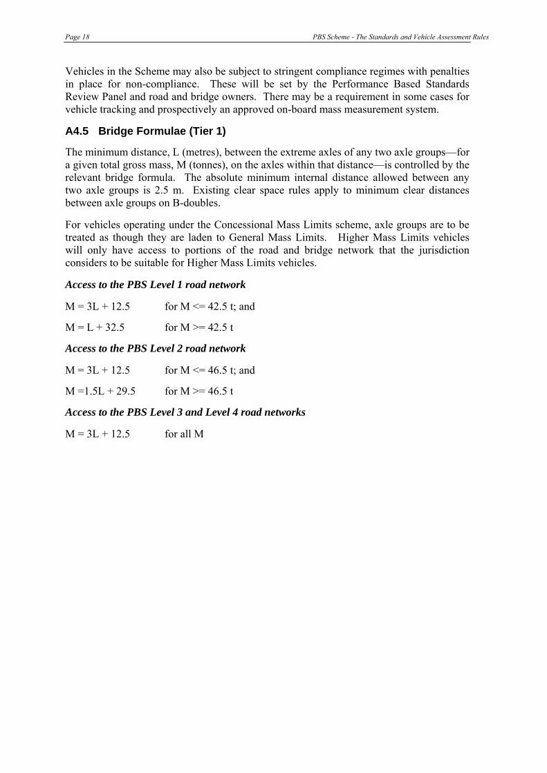
The minimum distance, L (metres), between the extreme axles of any two axle groups—for a given total gross mass, M (tonnes), on the axles within that distance—is controlled by the relevant bridge formula. The absolute minimum internal distance allowed between any two axle groups is 2.5 m. Existing clear space rules apply to minimum clear distances between axle groups on B-doubles.
For vehicles operating under the Concessional Mass Limits scheme, axle groups are to be treated as though they are laden to General Mass Limits. Higher Mass Limits vehicles will only have access to portions of the road and bridge network that the jurisdiction considers to be suitable for Higher Mass Limits vehicles.
Access to the PBS Level 1 road network
M = 3L + 12.5 for M <= 42.5 t; and
M = L + 32.5 for M >= 42.5 t
Access to the PBS Level 2 road network
M = 3L + 12.5 for M <= 46.5 t; and
M =1.5L + 29.5 for M >= 46.5 t
Access to the PBS Level 3 and Level 4 road networks
M = 3L + 12.5 for all M

PBS Scheme - The Standards and Vehicle Assessment Rules Page 19
APPENDIX B: [RESERVED]


PBS Scheme - The Standards and Vehicle Assessment Rules Page 21
APPENDIX C: THE SAFETY STANDARDS This Appendix specifies the safety standards that must be met by a vehicle to enable it to participate in the Scheme. The safety standards are:
Table 3. Safety Standards
Safety Standard Page C1: Startability 22 C2: Gradeability 24 C3: Acceleration Capability 27 C4: Overtaking Provision [reserved]
C5: Tracking Ability on a Straight Path 30 C6: Ride Quality (Driver Comfort) 34 C7: Low-Speed Swept Path 35 C8: Frontal Swing 39 C9: Tail Swing 46 C10: Steer-Tyre Friction Demand 48 C11: Static Rollover Threshold 51 C12: Rearward Amplification 56 C13: High-Speed Transient Offtracking 61 C14: Yaw Damping Coefficient 64 C15: Handling Quality (Understeer/Oversteer) 67 C16: Directional Stability Under Braking 68
Page 22 PBS Scheme - The Standards and Vehicle Assessment Rules
C1. STARTABILITY
C1.1 Purpose and intent
(a) Purpose
The primary purpose of this standard is to manage safety risk associated with starting on grade by ensuring that a vehicle participating in the Scheme has adequate starting capability on grades.
(b) Intent
A vehicle participating in the Scheme must be capable of starting on the steepest grade it has to negotiate on the nominated route when operating at its maximum allowed gross mass, otherwise it can become a safety risk and an inconvenience to other road users.
A combination vehicle that is stopped on a grade beyond its capability will either require that its units be separated and moved or require the use of heavy haulage equipment to move it to a location where it can restart.
C1.2 Definition
(a) Summary statement
The ability to commence forward motion on specified upgrade.
(b) Detailed statement
When operating at maximum laden mass, a vehicle participating in the Scheme must be able to commence and maintain steady forward motion from a standing start on a pavement section of specified upgrade. Momentary reverse motion (downhill) at commencement, associated with the release of brakes and clutch engagement, or similar, is acceptable provided uphill forward motion is subsequently achieved and maintained.
C1.3 Measure
(a) Performance value
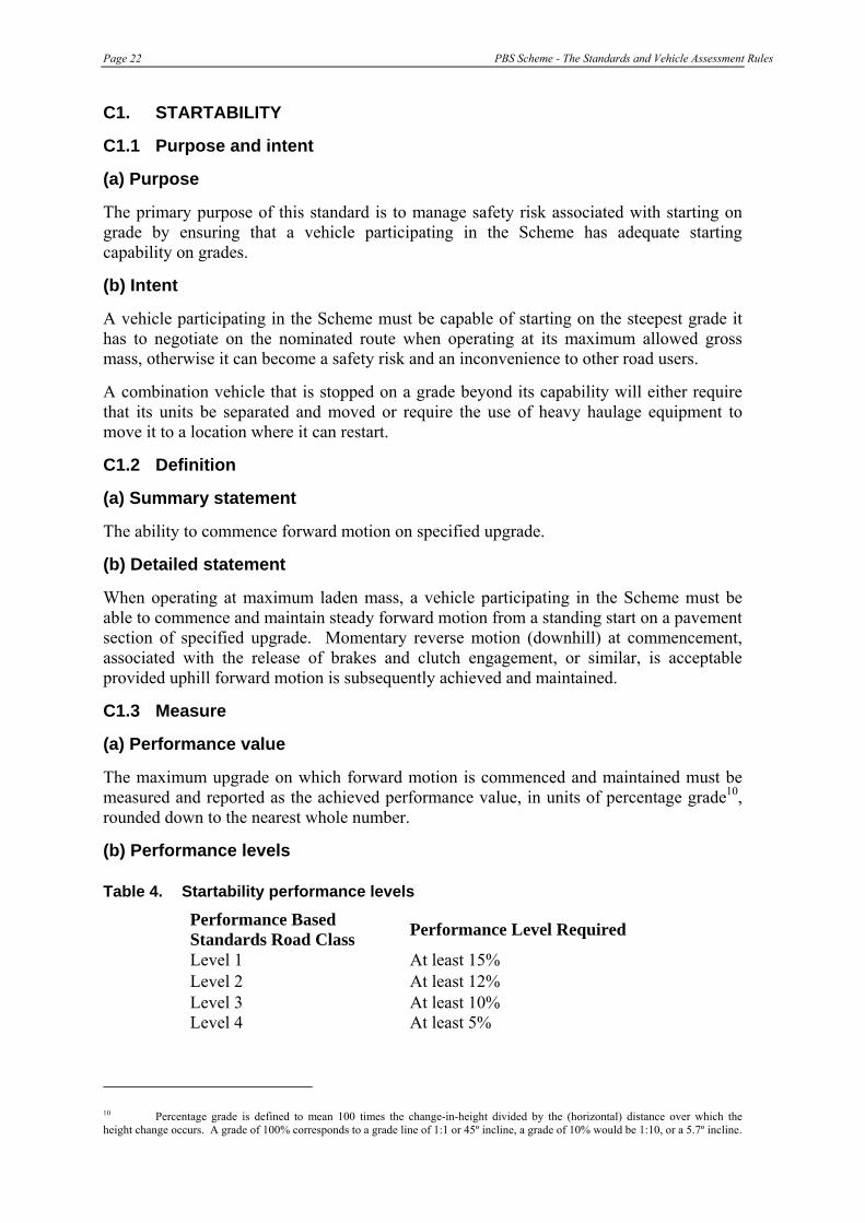
The maximum upgrade on which forward motion is commenced and maintained must be measured and reported as the achieved performance value, in units of percentage grade10, rounded down to the nearest whole number.
(b) Performance levels
Table 4. Startability performance levels
Performance Based Standards Road Class Performance Level Required
Level 1 At least 15% Level 2 At least 12% Level 3 At least 10% Level 4 At least 5%
10 Percentage grade is defined to mean 100 times the change-in-height divided by the (horizontal) distance over which the height change occurs. A grade of 100% corresponds to a grade line of 1:1 or 45º incline, a grade of 10% would be 1:10, or a 5.7º incline.
PBS Scheme - The Standards and Vehicle Assessment Rules Page 23
C1.4 Test specification
(a) Test load
The vehicle being assessed must be loaded to its maximum laden mass. Each tyre on the vehicle must have a tread depth of at least 90% of the original value over the whole tread width and circumference of the tyre. Each tyre must be inflated to a pressure within the range as specified by the vehicle and/or tyre manufacturer.
(b) Test conditions
The full length of the vehicle being assessed must be on an upgrade appropriate to the road classification level. The test site must have uniform, smooth, dry, hard pavement, which is free from contaminants. The surface must have a coefficient of friction value, μpeak, at the tyre/road contact surface of not more than 0.80.
(c) Test procedure
From a standing start on a slope having an upgrade not less than the specified grade, the vehicle being assessed must commence and maintain steady forward motion. Steady forward motion on the specified grade is achieved when the vehicle’s speed is either constant or increasing for a distance of at least 5 metres.
(d) Test method
Numerical modelling (computer-based simulation) or field-testing.

Page 24 PBS Scheme - The Standards and Vehicle Assessment Rules
C2: GRADEABILITY
C2.1 Purpose and intent
(a) Purpose The primary purpose of this standard is to manage safety risk associated with travel on grade by ensuring that a vehicle participating in the Scheme has the capability to maintain acceptable speeds on upgrades.
(b) Intent When operating at the maximum allowable gross mass, vehicles participating in the Scheme must be able to maintain a specified minimum speed on upgrades. This is desirable in order to minimise traffic congestion or delays to other vehicles travelling in the same direction. Further, heavy vehicles travelling on grade that impede traffic are known to increase accident rates on two lane rural highways (Khan et al, 1990).
Gradeability is applicable to all heavy vehicle operations – in urban, rural/regional and remote areas – and to all vehicles participating in the Scheme. In addition to safety considerations and concerns, gradeability also influences vehicle productivity, route selection and access.
The vehicle-related factors that determine startability also influence gradeability. However, a vehicle may be designed to maximise startability at the expense of its gradeability performance (geared low). Similarly, if optimised for gradeability it may not meet the startability requirement. For this reason both startability and gradeability must be within acceptable limits for a vehicle participating in the Scheme.
PART (A) MAINTAIN MOTION
C2.2 Definition
(a) Summary statement
The ability to maintain forward motion on specified upgrade.
(b) Detailed statement
When operating at maximum laden mass, a vehicle participating in the Scheme must be able to maintain steady forward motion on a pavement section of specified upgrade. An initial change in speed associated with the transition from the approach to the upgrade is acceptable, provided steady forward motion can be maintained on the upgrade.
C2.3 Measure
(a) Performance value
The maximum upgrade on which steady forward motion is maintained must be measured and reported as the achieved performance value, in units of percentage grade rounded down to the nearest whole number.

PBS Scheme - The Standards and Vehicle Assessment Rules Page 25
(b) Performance levels
Table 5. Gradeability - Part (a) Maintain Motion performance levels
Performance Based Standards Road Class
Performance Level Required
Level 1 At least 20% Level 2 At least 15% Level 3 At least 12% Level 4 At least 8%
C2.4 Test specification
(a) Test load
The vehicle being assessed must be loaded to its maximum laden mass. Each tyre on the vehicle must have a tread depth of at least 90% of the original value over the whole tread width and circumference of the tyre. Each tyre must be inflated to the pressure as specified by the vehicle and/or tyre manufacturer.
(b) Test conditions
Same as for startability. Additionally, the upgrade must be of sufficient length to allow steady forward motion to be established. The full length of the vehicle being assessed must be on the upgrade. The test site must have uniform, smooth, dry, hard pavement, which is free from contaminants. The surface must have a coefficient of friction value, μpeak, at the tyre/road contact surface of not more than 0.80.
(c) Test procedure
With the vehicle being assessed in forward motion on a slope having an upgrade not less than the specified grade, it must maintain steady forward motion. Steady forward motion is achieved when the vehicle’s forward speed on the upgrade is either constant or increasing for a distance of at least 5 metres.
(d) Test method
Numerical modelling (computer-based simulation) or field-testing.
PART (B) MAINTAIN SPEED
C2.5 Definition
(a) Summary statement
The ability to maintain a minimum speed on a specified upgrade.
(b) Detailed statement
When operating at maximum laden mass, a vehicle participating in the Scheme must be able to maintain a specified minimum speed on a pavement section having an upgrade of not less than 1%. An initial change in speed associated with the transition from the

Page 26 PBS Scheme - The Standards and Vehicle Assessment Rules
approach to the upgrade is acceptable, provided the specified minimum speed is maintained on the upgrade.
C2.6 Measure
(a) Performance value
The minimum sustained steady speed must be measured and recorded as the achieved performance value, in units of km/h rounded down to the nearest whole number.
(b) Performance levels
Table 6. Gradeability - Part (b) Maintain Speed performance levels
Performance Based Standards Road Class
Performance Level Required
Level 1 At least 80 km/h Level 2 At least 70 km/h Level 3 At least 70 km/h Level 4 At least 60 km/h
C2.7 Test specification
(a) Test load
The vehicle being assessed must be loaded to its maximum laden mass. Each tyre on the vehicle must have a tread depth of at least 90% of the original value over the whole tread width and circumference of the tyre. Each tyre must be inflated to the pressure as specified by the vehicle and/or tyre manufacturer.
(b) Test conditions
The full length of the vehicle being assessed must be on an upgrade. The test site must have uniform, smooth, dry, hard pavement, which is free from contaminants. The surface must have a coefficient of friction value, μpeak, at the tyre/road contact surface of not more than 0.80.
(c) Test procedure
With the vehicle being assessed in forward motion on a slope having an upgrade of not less than 1%, steady forward motion must be maintained at a speed at least equal to the specified minimum speed. Steady forward motion is when the forward speed of the vehicle on the upgrade is either constant or increasing for a period of at least 5 seconds.
(d) Test method
Numerical modelling (computer-based simulation) or field-testing.
PBS Scheme - The Standards and Vehicle Assessment Rules Page 27
C3: ACCELERATION CAPABILITY
C3.1 Purpose and intent
(a) Purpose The primary purpose of this standard is to manage safety risk associated with travel through intersections and rail crossings by specifying minimum times for a vehicle participating in the Scheme to accelerate from rest, to increase speed, and travel specified distances.
(b) Intent Acceleration capability is of primary concern to long or slow vehicles and addresses issues associated with intersection clearance times and rail level crossings. Heavy vehicles that require long times to accelerate to speed will take too long to clear intersections or railway level crossings, causing congestion and delays to through traffic, as well as posing a threat to safety if sight distances are inadequate. At an unsignalised intersection the probability of finding a gap in opposing traffic decreases as the size of the gap required increases. Signalised intersections operate on phase times that, where possible. should permit most heavy vehicles to clear the intersection in the allocated time.
Acceleration capability has an effect on the productivity of heavy vehicles in urban traffic, the capacity of the intersection and traffic congestion.
C3.2 Definition
(a) Summary statement
The ability to accelerate either from rest or to increase speed on a road with no grade.
(b) Detailed statement
When operating at maximum laden mass, a vehicle participating in the Scheme must be able to accelerate from rest, and travel 100 m on a road with no grade within a specified time.
C3.3 Measure
(a) Performance value
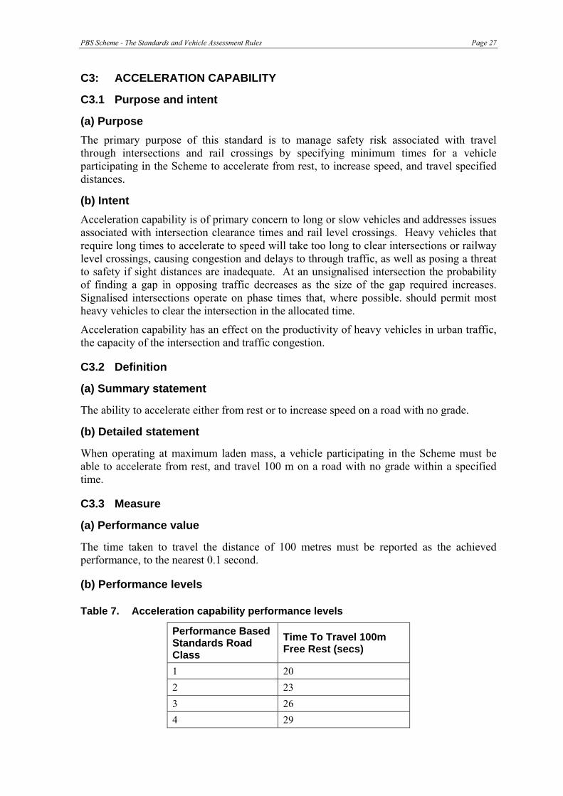
The time taken to travel the distance of 100 metres must be reported as the achieved performance, to the nearest 0.1 second.
(b) Performance levels
Table 7. Acceleration capability performance levels
Performance Based Standards Road Class
Time To Travel 100m Free Rest (secs)
1 20 2 23 3 26 4 29
Page 28 PBS Scheme - The Standards and Vehicle Assessment Rules
C3.4 Test specifications
(a) Test load
The vehicle being assessed must be loaded to its maximum laden mass. Each tyre on the vehicle must have a tread depth of at least 90% of the original value over the whole tread width and circumference of the tyre. Each tyre must be inflated to the pressure as specified by the vehicle and/or tyre manufacturer.
(b) Test conditions
The full length of the vehicle being assessed must be on a site with zero grade throughout the test (except for assessment by testing – see Appendix F). The test site must have uniform, smooth, dry, hard pavement, which is free from contaminants. The surface must have a coefficient of friction value, μpeak, at the tyre/road contact surface of not more than 0.80.
(c) Test procedure
From a standing start the vehicle being assessed must accelerate, changing through the gears as required, over a distance of at least 100 metres.
The point of commencement of acceleration should be taken as the moment forward motion starts.
(d) Test method
Numerical modelling (computer-based simulation) or field-testing.

PBS Scheme - The Standards and Vehicle Assessment Rules Page 29
C4: OVERTAKING PROVISION
The requirements for Overtaking Provision have been moved to the Network Classification Guidelines as a key component of classifying the heavy vehicle freight network. This allows the standard to be applied to the Performance Based Standards network without diminishing the intent of the standard, whilst improving the process for the assessment of individual applications.
To assist in the application of the Network Classification Guidelines, the maximum vehicle lengths for each road class are as set out below. For heavy vehicles participating in the Scheme that wish to gain access to a specific network level but exceed the maximum permitted length for that level, an individual route assessment will need to be carried out.
Table 8. Network classification by vehicle length
Network Access by Vehicle Length, L (m) Vehicle
PerformanceLevel Access Class
‘A’ Access Class
‘B’
Level 1 L ≤ 20 (General Access*)
Level 2 L ≤ 26 26 < L ≤ 30
Level 3 L ≤ 36.5 36.5 < L ≤ 42
Level 4 L ≤ 53.5 53.5 < L ≤ 60
* General Access is subject to a 50 tonne gross mass limit, posted local restrictions and restrictions or limitations specified by the jurisdiction.

Page 30 PBS Scheme - The Standards and Vehicle Assessment Rules
C5: TRACKING ABILITY ON A STRAIGHT PATH
C5.1 Purpose and intent
(a) Purpose The primary purpose of this standard is to manage safety risk associated with lane width and lateral clearance by ensuring that a vehicle participating in the Scheme remains within its traffic lane when travelling at high speed on straight roads with uneven surfaces.
(b) Intent When the hauling unit of a heavy vehicle follows a straight path along a section of road, it is both a practical requirement and necessary for safe operation that the rear of the vehicle follows with adequate fidelity and tracks within a specified lane width. Vehicles that require more lane width than is available present a risk to safety and the infrastructure when crossing the centre-line when being overtaken or passed, and when leaving the pavement seal causing edge break-off and aggravating shoulder drop. If large enough and the conditions sufficiently adverse, shoulder drop can initiate a rollover.
In practice, each trailer in a combination vehicle will undergo small lateral excursions from the path of its lead unit as it responds to the driver’s steering actions, road surface unevenness and other external disturbances, such as cross winds. The ability of the trailing units to faithfully track along the same path as the hauling unit is referred to as tracking ability. Tracking ability depends on a range of vehicle-related factors, including: number of trailers and the location and type of coupling between them (turntable or pintle hitch); alignment of axles; suspension geometry (roll and bump steer effects); tyre cornering stiffness; vehicle length; and speed.
C5.2 Definition
(a) Summary statement
The total swept width while travelling on a straight path, including the influence of variations due to crossfall, road surface unevenness and driver steering activity.
(b) Detailed statement
When operating at least favourable load condition and travelling along the specified straight path on a section of pavement having the specified unevenness and cross-slope characteristics, the total swept width of the vehicle being assessed in the specified test must be no greater than the specified value.
C5.3 Measure
(a) Performance value
The total swept width of the vehicle being assessed must be measured and reported over the specified test section as the achieved performance value, expressed in units of metres, rounded up to the nearest 0.1metre The swept width at any point along the straight path is the length of the straight-line segment intersecting all the path trajectories, measured in the ground plane and perpendicular to the direction of travel, as shown in Figures 1 to 3. For single unit and combination vehicles, the swept width along the path must be determined from the path trajectories of the outermost paths scribed in the ground plane by the vertical projections of the outermost reference point, or points of all vehicle units. The number of reference points must ensure that the swept width is measured to the defined accuracy. The reference points must be selected when the vehicle is on a flat level surface. Where

PBS Scheme - The Standards and Vehicle Assessment Rules Page 31
there is a choice of more than one reference point at any particular location, such as along the vertical outside corner of the front or rear of a vehicle unit, the outermost point nearest to the ground must be selected.
Figure 1. Perspective view illustration of front and rear outside-corner path
trajectories and swept width in the tracking ability on a straight path test.
* Note that the path trajectories of only 4 points are shown in the above example.)
Figure 2. Underside perspective view illustration showing typical
characteristics of the path trajectories and offsets due to cross slope.
Page 32 PBS Scheme - The Standards and Vehicle Assessment Rules
Figure 3. Close-up underside perspective view illustration showing both the
swept width envelope and Total Swept Width from the 4 path trajectories defined in Figures 1 and 2.
(b) Performance levels
Table 9. Tracking ability performance levels
Performance Based Standards Road Class Performance Level Required
Level 1 Not greater than 2.9 m Level 2 Not greater than 3.0 m Level 3 Not greater than 3.1 m Level 4 Not greater than 3.3 m
If the assessment is undertaken by numerical modelling, a test road conforming to the test conditions will be supplied to the assessor so that all assessments are undertaken under equal conditions. However, to allow for variations in computer models, the 99th percentile of the measured swept width will be accepted as meeting the performance level. With assessment by testing, a risk exists that one or two major bumps on the test section will not provide a reasonable test of the ability of the vehicle being assessed to meet the standard and again the 99th percentile of the measured swept width will be accepted as meeting the performance level.
C5.4 Test specification
(a) Test load
The vehicle being assessed must be loaded to the least favourable load condition. The maximum laden mass and the corresponding maximum axle group loads must not be exceeded. For standard test conditions, the tyres on the vehicle must have a tread depth of at least 90% of the original value over the whole tread width and circumference of the

PBS Scheme - The Standards and Vehicle Assessment Rules Page 33
tyres, and have no less than 100 km of running. Tyres must be inflated to pressures as specified by the vehicle and/or tyre manufacturer.
(b) Test conditions
The road pavement test section must be at least 1000 metres long and the surface must have an overall unevenness level in each wheel path of not less that 3.8 m/km IRI (International Roughness Index). The unevenness level in each wheel path reported every 100 m must be not less than 3.0 m/km IRI. The entire test section must have an average crossfall, falling to the left when viewed in the direction of travel, of not less than 3.0%. The average crossfall must have a crossfall standard deviation of not less than 1.0%.
For the numerical modelling, a standard set of road profiles will be supplied to the assessor. The standard profiles are taken from the work performed for Austroads described in Prem et al (1999). The profiles were used in the Performance Based Standards fleet analysis project that developed this and other standards (NRTC, 2002).
(c) Test procedure
The vehicle being assessed must traverse a road segment not less than 1000 metres long at a travel speed not less than 90 km/h. The vehicle must be driven in a normal manner at the specified speed while as closely as possible following a straight path that is either defined specifically for the task, such as a contrasting line, or by existing pavement edge line or centreline markings.
(d) Test method
Numerical modelling or field-testing. If performed by numerical modelling, as noted above a test road conforming to the test conditions specified above will be supplied by the Panel to the assessor.
Page 34 PBS Scheme - The Standards and Vehicle Assessment Rules
C6: RIDE QUALITY (DRIVER COMFORT)
C6.1 Purpose and intent
(a) Purpose The primary purpose of this standard is to manage safety risk by limiting driver whole-body vibration especially on uneven roads where travel speeds are high and vibration levels are expected to be significant.
(b) Intent The effect of whole-body vibration on heavy vehicle drivers is an important road safety and occupational health and safety issue for the road transport industry. Short-term exposure to high-intensity vibration can have adverse effects on motor processes and the sensory system (limb movements, sensing and response to motion, vision, and hearing) that can impair the driver’s ability to control the vehicle. This type of vibration can also lead to acute injuries. Further, long-term exposure to occupational whole-body vibration poses a health risk that can lead to chronic injuries associated with the back and abdominal regions of the human body.
While there appears to be a connection between whole-body vibration and driver comfort and health, vibration has been observed both to improve and to reduce proficiency. This may be because it fatigues or arouses or, because of increased task difficulty, motivates. These effects cannot be reliably predicted at present.
Ride vibration is influenced by a variety of factors, including vehicle load, suspension and tyre characteristics, prime mover wheelbase, seat location (fore-aft and height), seat transmissibility characteristics, road surface unevenness, speed, kingpin lead and trailer characteristics.
C6.2 Definition, measure and test specification
This standard has yet to be defined. Its three main components (a performance measure, a test procedure from which to obtain the performance measure and a performance level, or levels, to be satisfied) are not able to collectively be defined to an acceptable level of robustness at this time based on current research.
There are three (very similar) recognised standards11 for assessing whole-body vibration that could form the basis of defining the performance measure and performance level(s), but at this point in time there has yet to be developed a suitable test procedure from which to obtain measurements. It is important that the severity of the test procedure is at a level that allows good-performing vehicles to pass the standard and disallows poor-performing vehicles from passing the standard. Setting the severity at too low a level will potentially allow all vehicles to pass the standard, regardless of their performance. Conversely, setting the severity at too high a level may potentially disallow all vehicles.
The NTC has initiated a project to finalise this standard in its 2007/2008 work programme. A proposal will be submitted to the Australian Transport Council for approval in 2008 following consultation with industry and Transport Agency Chief Executives.
11 Australian Standard 2670, British Standard 6841, International Standard 2631
PBS Scheme - The Standards and Vehicle Assessment Rules Page 35
C7: LOW-SPEED SWEPT PATH
C7.1 Purpose and intent
(a) Purpose
The primary purpose of this standard is to manage safety risk associated with turns at intersections by limiting the road space required by a vehicle participating in the Scheme when making low-speed turns.
(b) Intent
When a long vehicle makes a low-speed turn at an intersection, the rear of the vehicle will follow a path that is inside the path taken by the front of the vehicle. This is known as low-speed offtracking. A high value of offtracking is undesirable because the vehicle, sweeping a wider path, will require more road space for turning than may be available. This may cause the vehicle to encroach into adjacent or opposing lanes, collide with parked or stopped vehicles, damage roadside furniture, endanger pedestrians, or the rear wheels may climb the kerb or fall off the edge of the pavement.
C7.2 Definition
(a) Summary statement
The maximum width of the swept path in a prescribed 90º low speed turn.
(b) Detailed statement
When operating at maximum laden mass and unladen, the maximum width of the swept path of a vehicle participating in the Scheme in the prescribed 90º turn performed at a speed of no more than 5 km/h must be no greater than the specified value.
C7.3 Measure
(a) Performance value
The maximum width of the swept path must be measured and reported as the achieved performance value, in units of metres rounded up to the nearest 0.1 metre. The maximum width of the swept path is the maximum distance, SPWmax, between the outer and inner path trajectories of the swept path envelope of the vehicle being assessed in the specified low-speed turn, shown in Figures 5 and 6. The maximum distance, SPWmax, is the straight-line segment intersecting both trajectories perpendicularly to their respective tangents at the intersection points. The swept path must be determined from the path trajectories of: 1) the outermost path scribed in the ground plane by the vertical projection of the furthest forward or outside point, or points, on the vehicle on the outside of the turn; and 2) the innermost path scribed in the ground plane by the vertical projection of the point, or points, on the vehicle on the inside of the turn. The above is summarised in Figures 4 to 6.

Page 36 PBS Scheme - The Standards and Vehicle Assessment Rules
Figure 4. Perspective view illustration of vehicle partway through the Performance Based Standards low-speed turn showing path trajectories.
Figure 5. Plan view illustration of path trajectories that define the vehicle’s swept path in the Performance Based Standards low-speed turn.

PBS Scheme - The Standards and Vehicle Assessment Rules Page 37
Figure 6. Plan view illustration of Maximum Width of Swept Path, SPWmax. Note that the line perpendicular to both path trajectories (shown dotted in the illustration) does not necessarily pass through the turn centre.
(b) Performance levels
Table 10. Low speed swept path performance levels
Performance Based Standards Road Class
Performance Level Required
Level 1 No greater than 7.4 m Level 2 No greater than 8.7 m Level 3 No greater than 10.6 m Level 4 No greater than 13.7 m
C7.4 Test specification
(a) Test load
The vehicle being assessed must be tested fully laden and unladen. When fully laden it must be loaded to its maximum allowed gross mass and the corresponding maximum allowed axle group loads must not be exceeded. For the purposes of measuring swept path, mirrors and signalling devices are ignored.
(b) Test conditions
The test site must have uniform, smooth, dry, hard pavement, which is free from contaminants. The surface must have a coefficient of friction value, μpeak, at the tyre/road contact surface of not more than 0.80.

Page 38 PBS Scheme - The Standards and Vehicle Assessment Rules
(c) Test procedure
The vehicle being assessed must be driven through the specified turn, unladen and laden, at a speed no greater than 5 km/h. The path of the specified turn that the driver will use to guide the vehicle must comprise straight tangent approaches to a 90º circular arc of 12.5 metre radius. The approaches to the turn must be of sufficient length to ensure:
(i) the entire vehicle is straight at the point where the 90º turn is commenced; and (ii) at the conclusion of the turn the vehicle travels far enough into the straight exit
segment to record the maximum width of the swept path.
The driver must ensure the entire vehicle is straight at the commencement of the turn (within 0.1 metre of the entry approach tangent). In the turn the driver must steer the vehicle along the specified path. The vehicle must be steered such that the vertical projection in the ground plane of the outer most point on the outer tyre sidewall nearest to the ground12, on the forward most outside steered-wheel, follows the specified path as illustrated in Figure 5. Using the above point as a reference, the driver must steer the vehicle along the specified path and maintain a lateral distance error between the reference point and the specified path not greater than 50 millimetres.
(d) Test method
Numerical modelling (computer-based simulation) or field-testing.
Figure 7. Illustration of outside wheel reference point.
12 This represents the outermost point on the tyre sidewall – including tyre bulge due to deflection – which is most likely to come into contact first with the kerb in a shallow angle strike.
PBS Scheme - The Standards and Vehicle Assessment Rules Page 39
C8: FRONTAL SWING
C8.1 Purpose and intent
(a) Purpose
The primary purpose of this standard is to manage safety risk by limiting the road space requirement of a vehicle participating in the Scheme when making a tight turn at low speed.
(b) Intent
In a low-speed turn the front overhang of the hauling unit (rigid truck, prime mover, bus and coach) will generally cause the path of the front outside corner to track outboard the path of the front outside steered wheel. This behaviour is known as frontal swing. A large amount of frontal swing is undesirable because the vehicle will require more road (and/or kerbside) space for turning than may be available. In some situations this may cause the vehicle to encroach into adjacent or opposing lanes, interfere with roadside objects, collide with parked or stopped vehicles, endanger pedestrians, or require reversing the vehicle in the middle of a turn.
In addition to the above, on the exit side of the turn, the path of the front outside corner of a semi-trailer with large front overhang may track outboard of the path of the front outside corner of the hauling unit. For these vehicles, the road space and safety implications are similar to those for the hauling unit described above.
Both of these aspects of frontal swing are controlled by this standard, and they are important in situations where a vehicle operates in an environment and traffic situations where tight turns are frequently required to be performed.
Part A of frontal swing tested by this performance measure specifically addresses issues related to the hauling unit. The second and third components (Parts B and C) of the frontal swing performance measure, which deal with the semi-trailer(s), are both measured on the exit side of the turn and perpendicular to the exit path. These relate to the distance the semi-trailer front outside corner tracks outside the path of the front outside corner of the unit ahead of it (prime mover or converter dolly); on a prime mover the front outside corner is the primary reference that the driver sees, knows and will use (assisted by side mirrors) to establish adequate clearance between the vehicle and road and/or kerbside objects adjacent to the path of the turn, to prevent collisions or conflicts. Part B controls the maximum of the difference between the two paths. It is referred to as the Maximum of Difference between frontal swing-out values, or frontal swing MoD. Part C of the measure, referred to as the Difference between the Maximum frontal swing-out values, or frontal swing DoM, places an upper limit on maximum swing-out of the front outside corner of the semi-trailer measured relative to the maximum swing-out of the prime mover.
The key parameters that influence frontal swing are the amount of front overhang forward of the steer axle, and for semi-trailers the amount of overhang forward of the kingpin. For a fixed amount of front-overhang, longer-wheelbases will generally increase frontal swing.
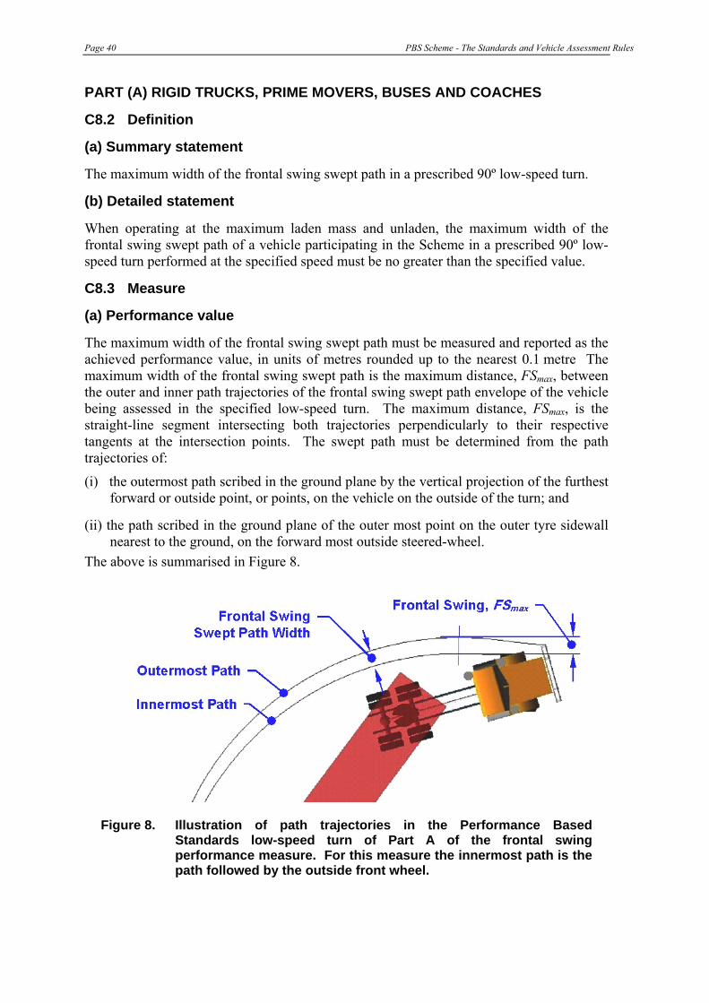
Page 40 PBS Scheme - The Standards and Vehicle Assessment Rules
PART (A) RIGID TRUCKS, PRIME MOVERS, BUSES AND COACHES
C8.2 Definition
(a) Summary statement
The maximum width of the frontal swing swept path in a prescribed 90º low-speed turn.
(b) Detailed statement
When operating at the maximum laden mass and unladen, the maximum width of the frontal swing swept path of a vehicle participating in the Scheme in a prescribed 90º low-speed turn performed at the specified speed must be no greater than the specified value.
C8.3 Measure
(a) Performance value
The maximum width of the frontal swing swept path must be measured and reported as the achieved performance value, in units of metres rounded up to the nearest 0.1 metre The maximum width of the frontal swing swept path is the maximum distance, FSmax, between the outer and inner path trajectories of the frontal swing swept path envelope of the vehicle being assessed in the specified low-speed turn. The maximum distance, FSmax, is the straight-line segment intersecting both trajectories perpendicularly to their respective tangents at the intersection points. The swept path must be determined from the path trajectories of:
(i) the outermost path scribed in the ground plane by the vertical projection of the furthest forward or outside point, or points, on the vehicle on the outside of the turn; and
(ii) the path scribed in the ground plane of the outer most point on the outer tyre sidewall nearest to the ground, on the forward most outside steered-wheel.
The above is summarised in Figure 8.
Figure 8. Illustration of path trajectories in the Performance Based Standards low-speed turn of Part A of the frontal swing performance measure. For this measure the innermost path is the path followed by the outside front wheel.
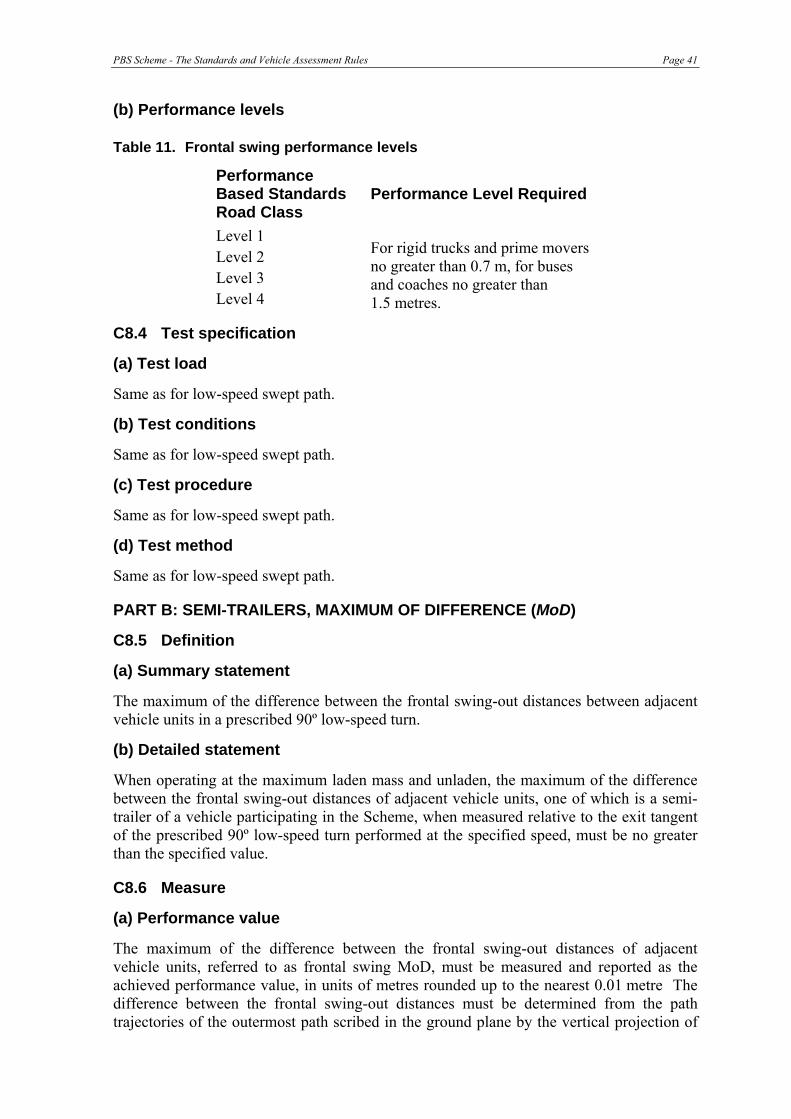
PBS Scheme - The Standards and Vehicle Assessment Rules Page 41
(b) Performance levels
Table 11. Frontal swing performance levels
Performance Based Standards Road Class
Performance Level Required
Level 1 Level 2 Level 3 Level 4
For rigid trucks and prime movers no greater than 0.7 m, for buses and coaches no greater than 1.5 metres.
C8.4 Test specification
(a) Test load
Same as for low-speed swept path.
(b) Test conditions
Same as for low-speed swept path.
(c) Test procedure
Same as for low-speed swept path.
(d) Test method
Same as for low-speed swept path.
PART B: SEMI-TRAILERS, MAXIMUM OF DIFFERENCE (MoD)
C8.5 Definition
(a) Summary statement
The maximum of the difference between the frontal swing-out distances between adjacent vehicle units in a prescribed 90º low-speed turn.
(b) Detailed statement
When operating at the maximum laden mass and unladen, the maximum of the difference between the frontal swing-out distances of adjacent vehicle units, one of which is a semi-trailer of a vehicle participating in the Scheme, when measured relative to the exit tangent of the prescribed 90º low-speed turn performed at the specified speed, must be no greater than the specified value.
C8.6 Measure
(a) Performance value
The maximum of the difference between the frontal swing-out distances of adjacent vehicle units, referred to as frontal swing MoD, must be measured and reported as the achieved performance value, in units of metres rounded up to the nearest 0.01 metre The difference between the frontal swing-out distances must be determined from the path trajectories of the outermost path scribed in the ground plane by the vertical projection of

Page 42 PBS Scheme - The Standards and Vehicle Assessment Rules
the furthest forward or outside point, or points, on each of two adjacent vehicle units, one of which is a semi-trailer. Frontal swing MoD is the maximum value of the straight-line segment intersecting both trajectories perpendicular to the low-speed turn exit tangent, as shown in Figures 9 to 12. If the frontal swing-out of the second vehicle unit is less than the frontal swing-out of the first vehicle unit throughout the entire turn then frontal swing MoD is not applicable and must be recorded as “not applicable”.
Figure 9. Perspective view illustration of path trajectories partway through the Performance Based Standards low-speed turn for Parts B and C of frontal swing MoD and DoM performance measures.
Figure 10. Perspective view illustration of Parts B and C of the frontal swing MoD and DoM performance measures looking along the exit tangent during the final stages of the low-speed turn.
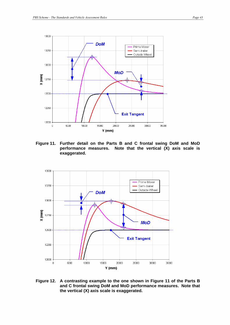
PBS Scheme - The Standards and Vehicle Assessment Rules Page 43
Figure 11. Further detail on the Parts B and C frontal swing DoM and MoD performance measures. Note that the vertical (X) axis scale is exaggerated.
Figure 12. A contrasting example to the one shown in Figure 11 of the Parts B and C frontal swing DoM and MoD performance measures. Note that the vertical (X) axis scale is exaggerated.

Page 44 PBS Scheme - The Standards and Vehicle Assessment Rules
(b) Performance levels
Table 12. Maximum difference of frontal swing path performance levels
Performance Based Standards Road Class
Performance Level Required
Level 1 Level 2 Level 3 Level 4
No greater than 0.40 metre
C8.7 Test specification
(a) Test load
Same as for low-speed swept path.
(b) Test conditions
Same as for low-speed swept path.
(c) Test procedure
Same as for low-speed swept path.
(d) Test method
Same as for low-speed swept path.
PART C: SEMI-TRAILERS, DIFFERENCE OF MAXIMA (DoM)
C8.8 Definition
(a) Summary statement
The difference between the maximum frontal swing-out distances between adjacent vehicle units in a prescribed 90º low-speed turn.
(b) Detailed statement
When operating at the maximum laden mass and unladen, the difference between the maximum frontal swing-out distances of adjacent vehicle units of a vehicle participating in the Scheme, when measured relative to the exit tangent of the prescribed 90º low-speed turn performed at the specified speed, must be no greater than the specified value.
C8.9 Measure
(a) Performance value
The difference between the maximum frontal swing-out distances of adjacent vehicle units, referred to as frontal swing DoM, must be measured and reported as the achieved performance value, in units of metres rounded up to the nearest 0.01 metre The difference between the maximum values of frontal swing-out distances must be determined from the path trajectories of the outermost paths scribed in the ground plane by the vertical projection of the furthest forward or outside point, or points, on each of two adjacent vehicle units, one of which is a semi-trailer. Frontal swing DoM is the length difference

PBS Scheme - The Standards and Vehicle Assessment Rules Page 45
between the two longest line segments perpendicular to the low-speed turn exit tangent intersecting it and one of the path trajectories, as shown in Figures 9 to 12. A negative value of DoM must be reported when the frontal swing-out of the second vehicle unit is less than the frontal swing-out of the first unit, examples are shown in Figures 10 and 11. If MoD is recorded as “not applicable”, DoM must also be recorded as “not applicable”.
(b) Performance levels
Table 13. Difference of maximum frontal swing out for performance levels
Performance Based Standards Road Class
Performance Level Required
Level 1 Level 2 Level 3 Level 4
No greater than 0.20 metre
C8.10 Test specifications
(a) Test load
Same as for low-speed swept path.
(b) Test conditions
Same as for low-speed swept path.
(c) Test procedure
Same as for low-speed swept path.
(d) Test method
Same as for low-speed swept path.

Page 46 PBS Scheme - The Standards and Vehicle Assessment Rules
C9: TAIL SWING
C9.1 Purpose and intent
(a) Purpose
The primary purpose of this standard is to manage safety risk by limiting the road space requirement of a vehicle participating in the Scheme when making a tight turn at low speed.
(b) Intent
Tail swing is important in situations where vehicle units with a large amount of rear overhang operate in an environment where tight turns are frequently required. Where tail swing is large, the rear outside corner of a rigid truck, bus or coach, prime mover or semi-trailer may swing-out a significant distance at the commencement of a turn. For conventional vehicles tail swing is only significant during commencement of a turn, but it must be tested on the entry approach and exit to the turn when a vehicle is towing trailers with steerable axles.
In urban operations, vehicles with significant rear overhang (such as route buses or semi-trailers), and/or coupling rear overhangs (such as car carriers with the turntable located behind the drive axle) will exhibit significant amounts of tail swing when negotiating tight manoeuvres (such as buses and coaches exiting kerbside pickup areas). Collisions with vehicles in adjacent lanes (including cyclists) and roadside objects may result.
C9.2 Definition
(a) Summary statement
The maximum outward lateral displacement of the outer rearmost point on a vehicle unit during the initial and final stages of a prescribed 90º low speed turn.
(b) Detailed statement
When operating at the maximum laden mass and unladen, the maximum outward lateral displacement of the outer rearmost point on a vehicle unit of a vehicle participating in the Scheme during the initial and final stages of a prescribed 90º low-speed turn performed at the specified speed must be no greater than the specified value.
C9.3 Measure
(a) Performance value The maximum tail swing during the initial and final stages of the prescribed turn, referred to as TSentry and TSexit, respectively, must be measured and reported as the achieved performance value, in units of metres rounded up to the nearest 0.01 metre. Tail swing must be determined from the path trajectory of the outermost path scribed in the ground plane by the vertical projection of the furthest rearward or outside point, or points, on the vehicle unit having the greatest tail swing.
On the entry side of the turn, tail swing is the length of the longest line segment perpendicular to the low-speed turn entry tangent intersecting it and the path trajectory, similar to that shown in Figure 13.
On the exit side of the turn, tail swing is the length of the longest line segment perpendicular to the low-speed turn exit tangent intersecting it and the path trajectory, the
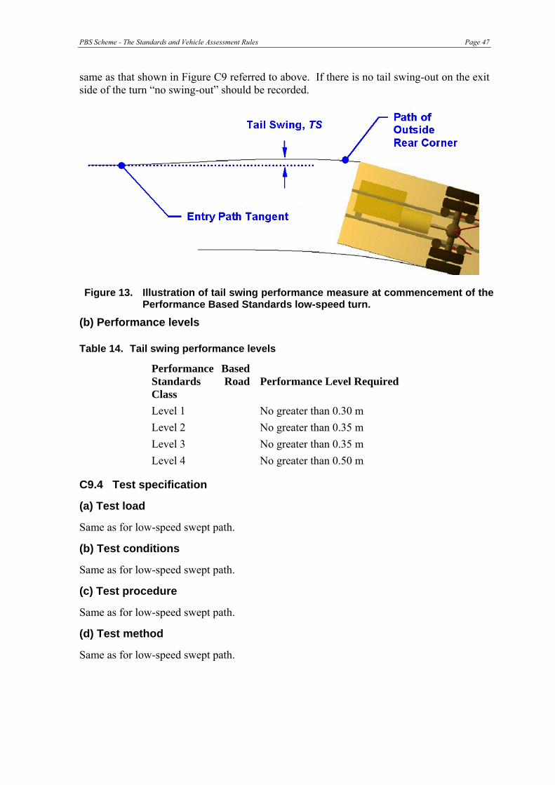
PBS Scheme - The Standards and Vehicle Assessment Rules Page 47
same as that shown in Figure C9 referred to above. If there is no tail swing-out on the exit side of the turn “no swing-out” should be recorded.
Figure 13. Illustration of tail swing performance measure at commencement of the Performance Based Standards low-speed turn.
(b) Performance levels
Table 14. Tail swing performance levels
Performance Based Standards Road Class
Performance Level Required
Level 1 No greater than 0.30 m Level 2 No greater than 0.35 m Level 3 No greater than 0.35 m Level 4 No greater than 0.50 m
C9.4 Test specification
(a) Test load
Same as for low-speed swept path.
(b) Test conditions
Same as for low-speed swept path.
(c) Test procedure
Same as for low-speed swept path.
(d) Test method
Same as for low-speed swept path.

Page 48 PBS Scheme - The Standards and Vehicle Assessment Rules
C10: STEER-TYRE FRICTION DEMAND
C10.1 Purpose and intent
(a) Purpose
The primary purpose of this standard is to manage safety risk by limiting the likelihood of a vehicle participating in the Scheme losing steering control when making a tight turn at low speed.
(b) Intent
During a small-radius turn at low-speed, loss of steering will occur when the available tyre/road friction limit at the steer-tyres is exceeded. In this situation the vehicle will tend to “plough straight ahead” exhibiting significant heavy understeer risking low-speed collisions with other vehicles or roadside objects. This phenomenon has been observed to occur on the hauling units of multi-combination vehicles (road trains) featuring tri-axle drive systems that have a widely spread axle layout. This is generally not an issue for prime movers with single-axle (or tandem-axle) drive systems, and less of an issue for prime movers equipped with twin-steer axles.
The problem of friction demand and “steerability” in a low-speed turn is greatest when the axle spread on the drive group is large and the prime mover wheelbase is small. Fore-aft and lateral forces from the towed trailers that are imposed on the prime mover kingpin, and kingpin lead will also influence friction demand on the steer tyres. Increasing the vertical load on the steer tyres, or decreasing the drive group load also serves to decrease the friction demand on the steer tyres.
C10.2 Definition
(a) Summary statement
The maximum friction level demanded of the steer tyres of the hauling unit in a prescribed 90º low speed turn.
(b) Detailed statement
When operating at the maximum allowed gross mass and unladen, the maximum friction level demanded of the steer tyres of the hauling in a prescribed 90º low-speed turn performed at the specified speed must be no greater than the specified value.
C10.3 Measure
(a) Performance value The maximum value of steer tyre friction demand must be measured and reported as the achieved performance value, in percentage units, rounded up to the nearest 1%. The friction demand of an axle or axle group is given by the following expression:
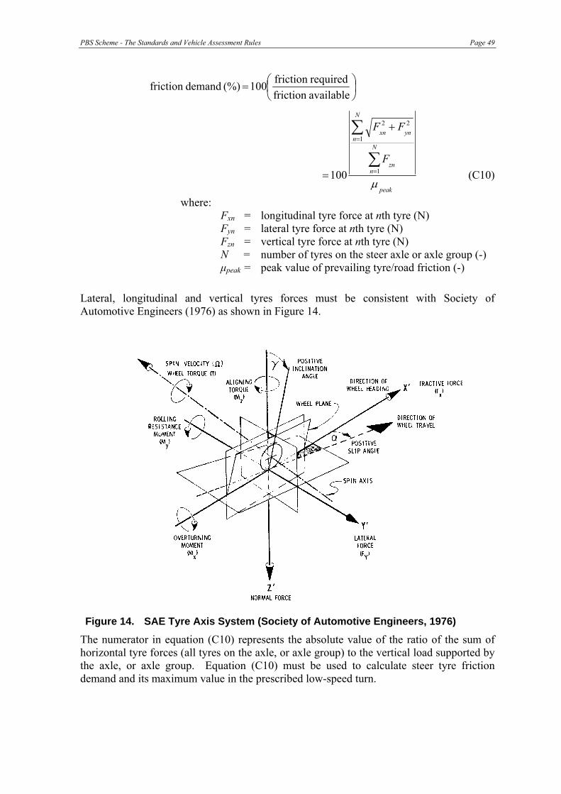
PBS Scheme - The Standards and Vehicle Assessment Rules Page 49
⎟⎠⎞
⎜⎝⎛=
availablefriction requiredfriction 100 (%) demandfriction
peak
N
nzn
N
nynxn
F
FF
μ
∑
∑
=
=
+
= 1
1
22
100 (C10)
where: Fxn = longitudinal tyre force at nth tyre (N) Fyn = lateral tyre force at nth tyre (N) Fzn = vertical tyre force at nth tyre (N) N = number of tyres on the steer axle or axle group (-) μpeak = peak value of prevailing tyre/road friction (-) Lateral, longitudinal and vertical tyres forces must be consistent with Society of Automotive Engineers (1976) as shown in Figure 14.
Figure 14. SAE Tyre Axis System (Society of Automotive Engineers, 1976)
The numerator in equation (C10) represents the absolute value of the ratio of the sum of horizontal tyre forces (all tyres on the axle, or axle group) to the vertical load supported by the axle, or axle group. Equation (C10) must be used to calculate steer tyre friction demand and its maximum value in the prescribed low-speed turn.
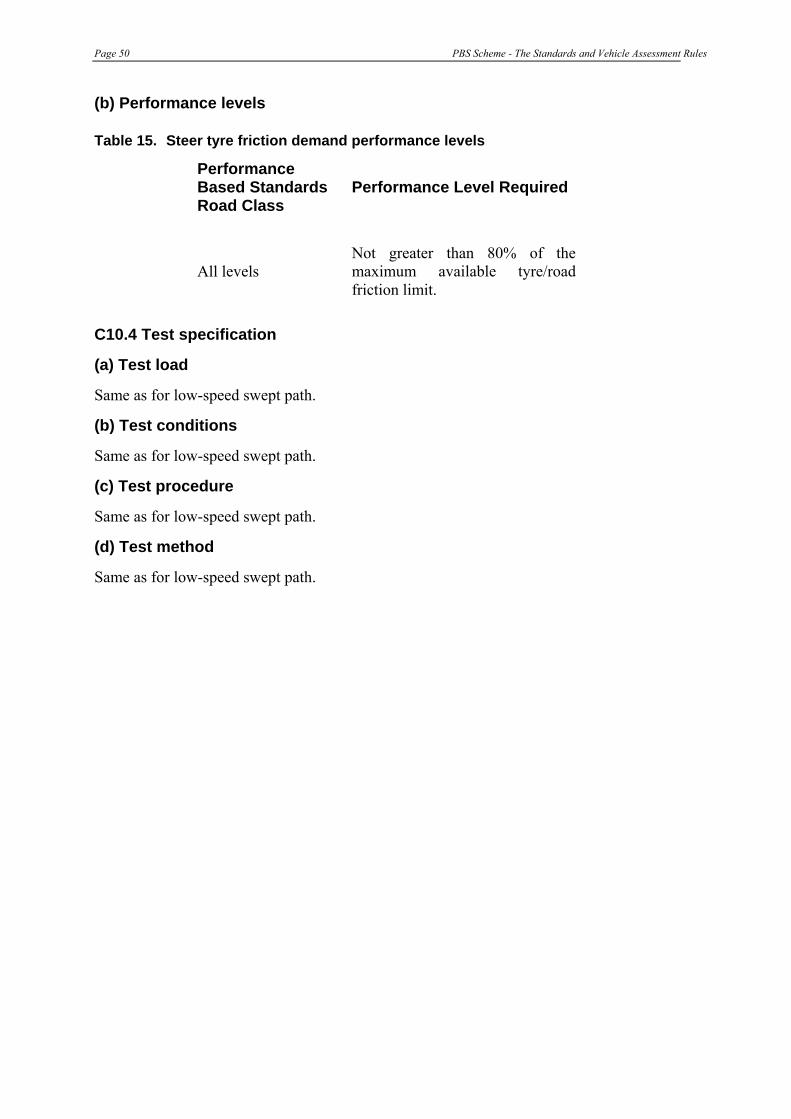
Page 50 PBS Scheme - The Standards and Vehicle Assessment Rules
(b) Performance levels
Table 15. Steer tyre friction demand performance levels
Performance Based Standards Road Class
Performance Level Required
All levels Not greater than 80% of the maximum available tyre/road friction limit.
C10.4 Test specification
(a) Test load
Same as for low-speed swept path.
(b) Test conditions
Same as for low-speed swept path.
(c) Test procedure
Same as for low-speed swept path.
(d) Test method
Same as for low-speed swept path.

PBS Scheme - The Standards and Vehicle Assessment Rules Page 51
C11: STATIC ROLLOVER THRESHOLD
C11.1 Purpose and intent
(a) Purpose The primary purpose of this standard is to manage safety risk by limiting the rollover tendency of a vehicle participating in the Scheme during steady turns.
(b) Intent A vehicle travelling along a curved path is subjected to an outward force and an overturning moment that is proportional to the lateral (or sideways) acceleration. Rollover occurs when the lateral acceleration that causes the overturning moment is sufficient to exceed the vehicle’s rollover stability threshold.
Rollover stability is the most significant safety issue and arguably the most important performance measure for heavy vehicles because it has been strongly linked to rollover crashes. Crashes that involve heavy vehicle rollover are strongly associated with severe injury and fatalities (Winkler et al, 2000).
The basic measure of rollover stability is static rollover threshold, usually expressed as a fraction of the acceleration due to gravity in units of ‘g’, where 1g is an acceleration of 9.807m/s2 corresponding to the force exerted by the earth’s gravitational field. High values of static rollover threshold imply better resistance to rollover.
Rollover stability is very sensitive to the ratio of the overall track width to the height above ground of the centre of gravity of the vehicle. Rollover stability increases either by increasing this width or by decreasing centre of gravity height. Suspension properties influence static rollover stability but they are generally of lesser importance when compared with the ratio of track width to centre of gravity height.
Rollover stability for multiple trailer combinations is much more complex than for single, rigid units and depends on the type of coupling between trailers. Trailers that are connected through a turntable are said to be “roll-coupled” and will rollover together as connected units, whereas full trailers (comprising a dolly and semi-trailer) connected by a pin coupling, can both roll and rollover independently of the other units in the combination. This means that any full trailer in a combination reaching its own stability limit first would rollover before other trailers in the combination. This also applies to entire roll-coupled units within combinations, such as B-double trailer combinations in triple- or quad-trailer configurations (AB-triple, AAB-quad, or BAB-quad).
C11.2 Definition
(a) Summary statement
The steady state level of lateral acceleration that a vehicle can sustain without rolling over during turning.
(b) Detailed statement
When operating up to the maximum laden mass and least favourable load conditions, the highest steady state level of lateral acceleration that a vehicle participating in the Scheme can sustain without rolling over must be no less than the specified value.

Page 52 PBS Scheme - The Standards and Vehicle Assessment Rules
C11.3 Measure (a) Performance value The rollover threshold of the vehicle, or vehicle unit with the lowest rollover stability, must be measured and reported as the achieved performance value, expressed as a fraction of the acceleration due to gravity in units of ‘g’, rounded down to the nearest 0.01g. For single unit vehicles, such as rigid trucks, buses and coaches, the rollover threshold is the lateral acceleration13 of the sprung mass centre of gravity measured at the point of rollover instability. For combination and multi-combination vehicles, the rollover threshold is the resultant lateral acceleration of any unit or roll-coupled set of units, AYrcu, as defined by equation C11.2a of this report, measured at the point of rollover instability.
Rollover instability is achieved when the lateral acceleration, or resultant lateral acceleration, starts to decrease with increasing roll angle, as illustrated in Figure 15 for a prime mover and semi-trailer vehicle or roll-coupled set. In general for heavy vehicles, the point of roll instability is also achieved when, or immediately after, the vertical load on all tyres along one side of the vehicle, excluding the tyres on the lightly loaded side of a steer axle(s) with soft springs, have reduced to zero.
Further, for combination and multi-combination vehicles, if the roll coupling between units in any set of units is either weak or is not continuous (such as found in double oscillating turntables or similar), and the roll angle14 of any unit within the set is greater than 30º, rollover instability must be assumed to have been achieved.
Vehicles that reach or exceed the tyre/road friction limits before rollover occurs, and achieve a steady state lateral acceleration that is not less than the required performance level are deemed to have acceptable rollover stability.
Figure 15. Typical axle lift-off sequence and rollover threshold for a prime mover and semi-trailer combination.
13 As defined in Society of Automotive Engineers (1976). 14 As defined in Society of Automotive Engineers (1976).

PBS Scheme - The Standards and Vehicle Assessment Rules Page 53
Vehicles that reach or exceed the tyre/road friction limits before rollover occurs, and achieve a steady state lateral acceleration that is not less than the required performance level are deemed to have acceptable rollover stability.
(b) Performance levels
Table 16. Static rollover threshold performance levels
Performance Based Standards Road Class
Performance Level Required
All levels
Road tankers hauling dangerous goods in bulk and buses and coaches not less than 0.40g. All other vehicles not less than 0.35g
(c) Calculation of resultant lateral acceleration of roll-coupled units This sub-section specifies the method that must be used to calculate the resultant lateral acceleration of a roll-coupled set of vehicle units in a multi-combination vehicle.
The parameter of prime interest is the resultant overturning moment and the key consideration being whether or not this moment is sufficient to cause the roll-coupled units to rollover. When the proximity of the roll-coupled units to rollover is expressed in terms of the resultant lateral acceleration, the static rollover threshold performance measure can be applied directly.
For the example of the 2 trailer roll-coupled rear units illustrated in Figure 16, the resultant lateral acceleration (ignoring the contribution from the dolly) when expressed in terms of roll moments is given by the following:
2211
222111
hmhmAYhmAYhmAYrcu +
+= (C11.1)
where:
AYrcu = resultant lateral acceleration of the roll-coupled units (m/s2) m1,2 = semi-trailer sprung mass (kg) h1,2 = height of sprung mass centre of gravity (m) AY1,2 = lateral acceleration15 of sprung mass centre of gravity
(m/s2)
15 As defined in Society of Automotive Engineers (1976)
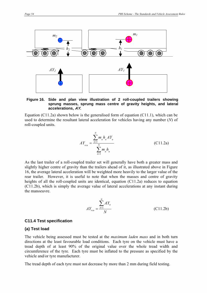
Page 54 PBS Scheme - The Standards and Vehicle Assessment Rules
AY1
h1h2
m1
AY2
m2
Figure 16. Side and plan view illustration of 2 roll-coupled trailers showing sprung masses, sprung mass centre of gravity heights, and lateral accelerations, AY.
Equation (C11.2a) shown below is the generalised form of equation (C11.1), which can be used to determine the resultant lateral acceleration for vehicles having any number (N) of roll-coupled units.
∑
∑
=
== N
nnn
N
nnnn
rcu
hm
AYhmAY
1
1 (C11.2a)
As the last trailer of a roll-coupled trailer set will generally have both a greater mass and slightly higher centre of gravity than the trailers ahead of it, as illustrated above in Figure 16, the average lateral acceleration will be weighted more heavily to the larger value of the rear trailer. However, it is useful to note that when the masses and centre of gravity heights of all the roll-coupled units are identical, equation (C11.2a) reduces to equation (C11.2b), which is simply the average value of lateral accelerations at any instant during the manoeuvre.
N
AYAY
N
nn
rcu
∑== 1 (C11.2b)
C11.4 Test specification
(a) Test load
The vehicle being assessed must be tested at the maximum laden mass and in both turn directions at the least favourable load conditions. Each tyre on the vehicle must have a tread depth of at least 90% of the original value over the whole tread width and circumference of the tyre. Each tyre must be inflated to the pressure as specified by the vehicle and/or tyre manufacturer.
The tread depth of each tyre must not decrease by more than 2 mm during field testing.

PBS Scheme - The Standards and Vehicle Assessment Rules Page 55
(b) Test conditions
The test site must have uniform, smooth, dry, hard pavement, which is free from contaminants. The surface must have a coefficient of friction value, μpeak, at the tyre/road contact surface of not more than 0.80.
(c) Test procedure
One of the following two test procedures must be used to measure static rollover threshold:
(i) Constant radius quasi-steady turn – The vehicle being assessed must be driven along the specified path at an initial speed that is at least 10 km/h slower than the speed at which the rollover instability will occur. The path of the specified turn that the driver will use to guide the vehicle must be circular and of radius not less than 100 metres. In the turn the driver must steer the vehicle along the specified path. The vehicle must be steered such that the vertical projection in the ground plane of a point at the centre of the forward-most steer axle follows the specified path. Using the above point as a reference, the driver must steer the vehicle along the specified path and maintain a lateral distance error between the reference point and the specified path not greater than 1.5 metres. From the initial speed, which must be maintained for at least 15 seconds on the specified path, the driver must increase the speed of the vehicle to the point of rollover instability at:
(a) an average rate, measured over any 5-second period, not greater than 0.5 km/h per second; or
(b) in increments of 2 km/h per lap.
This procedure is particularly relevant to long multi-combination vehicles that take much longer to reach steady turn conditions than short vehicles.
(ii) Tilt table – In accordance with recommended practice SAE J2180 (Society of Automotive Engineers, 1998).
(d) Test method
Numerical modelling (computer-based simulation) or field-testing.
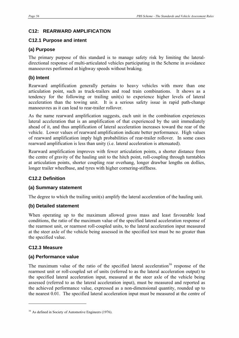
Page 56 PBS Scheme - The Standards and Vehicle Assessment Rules
C12: REARWARD AMPLIFICATION
C12.1 Purpose and intent
(a) Purpose The primary purpose of this standard is to manage safety risk by limiting the lateral-directional response of multi-articulated vehicles participating in the Scheme in avoidance manoeuvres performed at highway speeds without braking.
(b) Intent Rearward amplification generally pertains to heavy vehicles with more than one articulation point, such as truck-trailers and road train combinations. It shows as a tendency for the following or trailing unit(s) to experience higher levels of lateral acceleration than the towing unit. It is a serious safety issue in rapid path-change manoeuvres as it can lead to rear-trailer rollover.
As the name rearward amplification suggests, each unit in the combination experiences lateral acceleration that is an amplification of that experienced by the unit immediately ahead of it, and thus amplification of lateral acceleration increases toward the rear of the vehicle. Lower values of rearward amplification indicate better performance. High values of rearward amplification imply high probabilities of rear-trailer rollover. In some cases rearward amplification is less than unity (i.e. lateral acceleration is attenuated).
Rearward amplification improves with fewer articulation points, a shorter distance from the centre of gravity of the hauling unit to the hitch point, roll-coupling through turntables at articulation points, shorter coupling rear overhang, longer drawbar lengths on dollies, longer trailer wheelbase, and tyres with higher cornering-stiffness.
C12.2 Definition
(a) Summary statement
The degree to which the trailing unit(s) amplify the lateral acceleration of the hauling unit.
(b) Detailed statement
When operating up to the maximum allowed gross mass and least favourable load conditions, the ratio of the maximum value of the specified lateral acceleration response of the rearmost unit, or rearmost roll-coupled units, to the lateral acceleration input measured at the steer axle of the vehicle being assessed in the specified test must be no greater than the specified value.
C12.3 Measure
(a) Performance value
The maximum value of the ratio of the specified lateral acceleration16 response of the rearmost unit or roll-coupled set of units (referred to as the lateral acceleration output) to the specified lateral acceleration input, measured at the steer axle of the vehicle being assessed (referred to as the lateral acceleration input), must be measured and reported as the achieved performance value, expressed as a non-dimensional quantity, rounded up to the nearest 0.01. The specified lateral acceleration input must be measured at the centre of
16 As defined in Society of Automotive Engineers (1976).

PBS Scheme - The Standards and Vehicle Assessment Rules Page 57
the forward-most steer axle of the vehicle in the specified single lane-change manoeuvre defined in Section C12.4(c). The specified lateral acceleration output must be measured, and rearward amplification calculated, in accordance with Section C12.3 (c).
(b) Performance levels
Table 17. Rearward amplification performance levels
Performance Based Standards Road Class
Performance Level Required
All levels
Not greater than 5.7 times the static rollover threshold of the rearmost unit or roll-coupled set of units taking account of the stabilising influence of the roll coupling.
(c) Measurement of rearward amplification The general definition of rearward amplification presented in terms of lateral acceleration that must be used is given by the following:
unitvehiclefirstofAY
unitvehiclefollowingofAYRA
max
max= (C12.1)
The following is ascribed to the numerator and the denominator terms, respectively:
|AY|max of following vehicle unit = maximum absolute value of the lateral acceleration of the centre of mass of the sprung mass of the last vehicle unit (m/s2)
|AY|max of first vehicle unit = maximum absolute value of the lateral acceleration of the centre of the front axle (m/s2)
(i) Rigid vehicles and combination vehicles with a single rear unit
For rigid vehicles the lateral acceleration of the “following vehicle unit” described above in equation (12.1) is simply that of the centre of gravity of the sprung mass. That is, for rigid vehicles the “following vehicle unit” and “first vehicle unit” is the same unit.
Where the last unit comprises a single full trailer, namely, a dolly and a single semi-trailer, the lateral acceleration of the “following vehicle unit” described above is simply that of the centre of gravity of the sprung mass of the last semi-trailer.
(ii) Combination Vehicles with Roll-Coupled Rear Units
All units in a vehicle combination that are connected to each other either by turntables or other means of transmitting overturning-moments are said to be roll-coupled. The rearmost roll-coupled units (rrcu) in a vehicle combination are all the rear units that are connected by mechanical components or devices able to transmit overturning moments. The rrcu in 3 example vehicles is illustrated below in Figure 17.
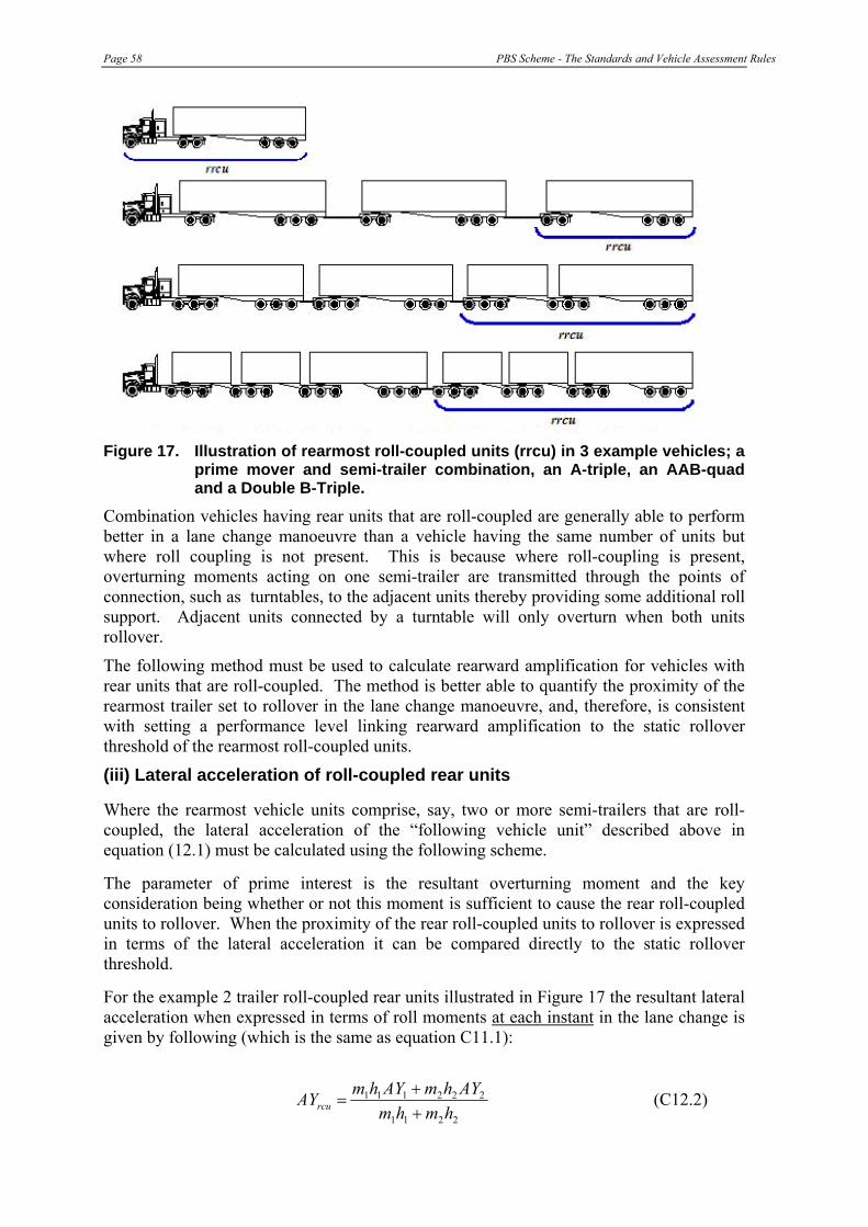
Page 58 PBS Scheme - The Standards and Vehicle Assessment Rules
Figure 17. Illustration of rearmost roll-coupled units (rrcu) in 3 example vehicles; a
prime mover and semi-trailer combination, an A-triple, an AAB-quad and a Double B-Triple.
Combination vehicles having rear units that are roll-coupled are generally able to perform better in a lane change manoeuvre than a vehicle having the same number of units but where roll coupling is not present. This is because where roll-coupling is present, overturning moments acting on one semi-trailer are transmitted through the points of connection, such as turntables, to the adjacent units thereby providing some additional roll support. Adjacent units connected by a turntable will only overturn when both units rollover.
The following method must be used to calculate rearward amplification for vehicles with rear units that are roll-coupled. The method is better able to quantify the proximity of the rearmost trailer set to rollover in the lane change manoeuvre, and, therefore, is consistent with setting a performance level linking rearward amplification to the static rollover threshold of the rearmost roll-coupled units.
(iii) Lateral acceleration of roll-coupled rear units
Where the rearmost vehicle units comprise, say, two or more semi-trailers that are roll-coupled, the lateral acceleration of the “following vehicle unit” described above in equation (12.1) must be calculated using the following scheme.
The parameter of prime interest is the resultant overturning moment and the key consideration being whether or not this moment is sufficient to cause the rear roll-coupled units to rollover. When the proximity of the rear roll-coupled units to rollover is expressed in terms of the lateral acceleration it can be compared directly to the static rollover threshold.
For the example 2 trailer roll-coupled rear units illustrated in Figure 17 the resultant lateral acceleration when expressed in terms of roll moments at each instant in the lane change is given by following (which is the same as equation C11.1):
2211
222111
hmhmAYhmAYhmAYrcu +
+= (C12.2)

PBS Scheme - The Standards and Vehicle Assessment Rules Page 59
where:
AYrcu = resultant lateral acceleration of the roll-coupled units (m/s2) m1,2 = semi-trailer sprung mass (kg) h1,2 = height of sprung mass centre of gravity (m) AY1,2 = lateral acceleration of sprung mass centre of gravity (m/s2)
Equation (C12.3a) shown below is the generalised form of equation (C12.2), which can be used to determine the resultant lateral acceleration for vehicles having any number (N) of roll-coupled rear units.
∑
∑
=
== N
nnn
N
nnnn
rcu
hm
AYhmAY
1
1 (C12.3a)
As the last trailer of a roll-coupled trailer set will generally have both a greater mass and slightly higher centre of gravity than the trailers ahead of it, as illustrated in Figure 16, the average lateral acceleration will be weighted more heavily to the larger value of the rear trailer. However, it is useful to note that when the masses and centre of gravity heights of all the roll-coupled rear units are identical, equation (C12.3a) reduces to equation (C12.3b), which is the mean of the lateral accelerations at any instant during the manoeuvre.
N
AYAY
N
nn
rcu
∑== 1 (C12.3b)
For a two-unit roll-coupled rear trailer set, with each unit having identical masses and centre of gravity heights, equation (C12.3b) shows that if the lateral accelerations are equal in magnitude and opposite in sign (making the average of AYrcu equal to zero), the motion of the roll-coupled rear trailers are exactly out of phase and the roll moments exactly balance each other, one trailer trying to roll to the left while the other is trying to roll to the right. While this is unlikely to occur in practice, it is a simple illustration of the positive influence of roll coupling.
The generalised version of equation (C12.1), which must be applied as part of this specification to vehicles with rear units that are roll-coupled is given below in equation (C12.4).
axlesteerofAY
unitvehiclelastofAYRA rcu
rcumax
max= (C12.4)
where:
|AYrcu|max of last vehicle unit = maximum absolute value of the resultant lateral acceleration of the roll-coupled rear units determined from equation (C12.3a) (m/s2)

Page 60 PBS Scheme - The Standards and Vehicle Assessment Rules
(iv) When all units are roll-coupled
As the input to the manoeuvre and excitation to the vehicle occurs at the hauling unit, the output/input relationship must clearly distinguish between the hauling unit (the steer input, or the source of the excitation) and the roll-coupled trailer set (the location where the response occurs). Therefore, when all units in a vehicle combination are roll-coupled, examples being a prime-mover and semi-trailer combination, B-doubles, B-triples and B-quad combinations, equation (C12.3a) should be applied to the semi-trailers. That is, the numerator of equation (C12.4) must include only a single semi-trailer for a prime mover and semi-trailer combination, and double, triple and quad semi-trailer sets for B-double, B-triple and B-quad combinations, respectively.
C12.4 Test specification
The vehicle must execute a single lane change manoeuvre in accordance with the “Single Lane-Change”, “Single Sine-Wave Lateral Acceleration Input”, specified in ISO 14791:2000(E) (International Standards Organisation, 2000)17. The basic course layout must be used. The manoeuvre must have a maximum lateral acceleration of not less than 0.15g and a steer frequency equal to 0.40 Hz. The test must be conducted at 88 km/h.
The driver must steer the vehicle along the specified path and maintain a lateral distance error between the reference point – taken to be the vertical projection in the ground plane of the centre of the forward most steer axle – and the specified path that is either:
• not greater than 30 mm; or,
• as specified in ISO 14791 such that the lateral acceleration and frequency of the input is not less than the value for the manoeuvre specified in the paragraph above.
If the specifications given in ISO 14791 differ to those described here, this specification takes precedence.
(a) Test load
In accordance with the “Single Lane-Change”, “Single Sine-Wave Lateral Acceleration Input”, specified in ISO 14791:2000(E) (International Standards Organisation, 2000).
Additionally, the vehicle being assessed must be tested laden at the least favourable load condition. If load asymmetries constitute the least favourable load condition then the vehicle must also be tested in both turn directions.
(b) Test conditions
In accord with the “Single Lane-Change”, “Single Sine-Wave Lateral Acceleration Input”, specified in ISO 14791:2000(E) (International Standards Organisation, 2000).
(c) Test procedure
In accord with the “Single Lane-Change”, “Single Sine-Wave Lateral Acceleration Input”, specified in ISO 14791:2000(E) (International Standards Organisation, 2000).
(d) Test method Numerical modelling or field-testing.
17 SAE J2179 has been superseded by ISO 14791. The test specified above is equivalent to the SAE J2179 single lane change.

PBS Scheme - The Standards and Vehicle Assessment Rules Page 61
C13: HIGH-SPEED TRANSIENT OFFTRACKING
C13.1 Purpose and intent
(a) Purpose The primary purpose of this standard is to manage safety risk by limiting the sway of the rearmost trailers of multi-articulated vehicles participating in the Scheme in avoidance manoeuvres performed without braking, at highway speeds.
(b) Intent In an abrupt evasive manoeuvre, the lateral displacement of the rear end of the last trailer of an articulated vehicle may “overshoot” the final path of the front axle of the hauling unit; the path achieved after the hauling unit has completed the manoeuvre and stabilised in its new straight ahead path parallel to its original path. The amount of overshoot, referred to as high-speed transient offtracking (and sometimes also referred to as trailer overshoot), can be viewed as an indication of the severity of intrusion into an adjacent or opposing lane, striking a kerb or dropping off the road seal (thus precipitating rollover) or collision with a roadside objects.
Crash studies suggest there is a trend of crash rate increasing with increased high-speed transient off tracking. The crash consequences of heavy vehicles performing avoidance manoeuvres will depend on the road environment and factors such as lane width and traffic volume. Where lane widths are narrow and traffic volumes are high, it is desirable for heavy vehicles to have lower levels of high-speed transient offtracking.
The parameters that influence rearward amplification have similar strong influences on High-Speed Transient Offtracking.
C13.2 Definition
(a) Summary statement
The lateral distance that the last-axle on the rearmost trailer tracks outside the path of the steer axle in a sudden evasive manoeuvre.
(b) Detailed statement
When operating up to the maximum laden mass and least favourable load conditions, the maximum lateral displacement between the specified point on the rearmost axle of the rearmost vehicle unit of a vehicle participating in the Scheme and the exit tangent in the specified test must be no greater than the specified value.
C13.3 Measure
(a) Performance value
The maximum lateral distance between the path trajectory of the specified point on the vehicle being assessed, measured in the ground plane and perpendicular to the exit tangent of the single lane change, single sine-wave lateral acceleration input, test course must be measured and reported as the achieved performance value, expressed in units of metres and rounded up to the nearest 0.1 metre. The specified point on the vehicle is the vertical projection in the ground plane of a point at the centre of the rearmost axle of the rearmost vehicle unit, as illustrated in Figure 18. When the maximum distance corresponds to an overshoot situation, as shown in Figure 18 and defined in Figure 19, the performance value must be recorded as a positive distance. When the maximum distance corresponds to an
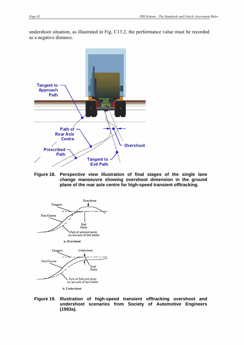
Page 62 PBS Scheme - The Standards and Vehicle Assessment Rules
undershoot situation, as illustrated in Fig, C13.2, the performance value must be recorded as a negative distance.
Figure 18. Perspective view illustration of final stages of the single lane change manoeuvre showing overshoot dimension in the ground plane of the rear axle centre for high-speed transient offtracking.
Figure 19. Illustration of high-speed transient offtracking overshoot and undershoot scenarios from Society of Automotive Engineers (1993a).
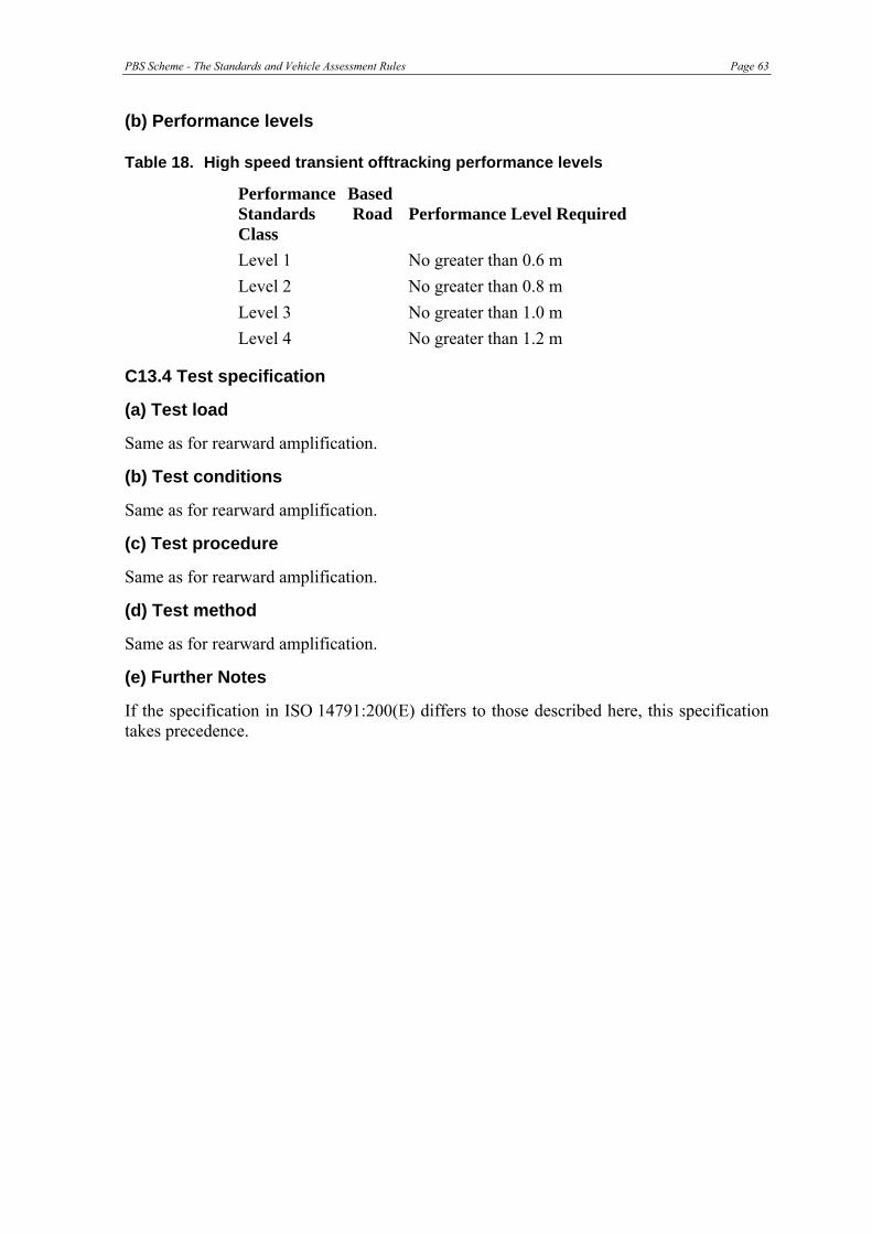
PBS Scheme - The Standards and Vehicle Assessment Rules Page 63
(b) Performance levels
Table 18. High speed transient offtracking performance levels
Performance Based Standards Road Class
Performance Level Required
Level 1 No greater than 0.6 m Level 2 No greater than 0.8 m Level 3 No greater than 1.0 m Level 4 No greater than 1.2 m
C13.4 Test specification
(a) Test load
Same as for rearward amplification.
(b) Test conditions
Same as for rearward amplification.
(c) Test procedure
Same as for rearward amplification.
(d) Test method
Same as for rearward amplification.
(e) Further Notes
If the specification in ISO 14791:200(E) differs to those described here, this specification takes precedence.
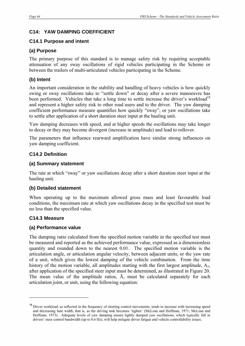
Page 64 PBS Scheme - The Standards and Vehicle Assessment Rules
C14: YAW DAMPING COEFFICIENT
C14.1 Purpose and intent
(a) Purpose The primary purpose of this standard is to manage safety risk by requiring acceptable attenuation of any sway oscillations of rigid vehicles participating in the Scheme or between the trailers of multi-articulated vehicles participating in the Scheme.
(b) Intent An important consideration in the stability and handling of heavy vehicles is how quickly swing or sway oscillations take to “settle down” or decay after a severe manoeuvre has been performed. Vehicles that take a long time to settle increase the driver’s workload18 and represent a higher safety risk to other road users and to the driver. The yaw damping coefficient performance measure quantifies how quickly “sway”, or yaw oscillations take to settle after application of a short duration steer input at the hauling unit.
Yaw damping decreases with speed, and at higher speeds the oscillations may take longer to decay or they may become divergent (increase in amplitude) and lead to rollover.
The parameters that influence rearward amplification have similar strong influences on yaw damping coefficient.
C14.2 Definition
(a) Summary statement
The rate at which “sway” or yaw oscillations decay after a short duration steer input at the hauling unit.
(b) Detailed statement
When operating up to the maximum allowed gross mass and least favourable load conditions, the maximum rate at which yaw oscillations decay in the specified test must be no less than the specified value.
C14.3 Measure
(a) Performance value
The damping ratio calculated from the specified motion variable in the specified test must be measured and reported as the achieved performance value, expressed as a dimensionless quantity and rounded down to the nearest 0.01. The specified motion variable is the articulation angle, or articulation angular velocity, between adjacent units, or the yaw rate of a unit, which gives the lowest damping of the vehicle combination. From the time history of the motion variable, all amplitudes starting with the first largest amplitude, A1, after application of the specified steer input must be determined, as illustrated in Figure 20. The mean value of the amplitude ratios, Ā, must be calculated separately for each articulation joint, or unit, using the following equation:
18 Driver workload, as reflected in the frequency of steering control movements, tends to increase with increasing speed
and decreasing lane width, that is, as the driving task becomes ‘tighter’ (McLean and Hoffman, 1971; McLean and Hoffman, 1973). Adequate levels of yaw damping ensure lightly damped yaw oscillations, which typically fall in drivers’ steer control bandwidth (up to 0.6 Hz), will help mitigate driver fatigue and vehicle controllability issues.

PBS Scheme - The Standards and Vehicle Assessment Rules Page 65
⎟⎟⎠
⎞⎜⎜⎝
⎛++++
−= −
n
n
AA
AA
AA
AA
nA 2
5
3
4
2
3
1 ...2
1 (C14a)
Amplitude An must be at least 5% of A1 and the calculation of Ā must be based upon at least 6 amplitudes. The damping ratio, D, is calculated according to the following formula:
( )( ) ( )[ ]2 2 ln2
lnDA
A
+=
π, (C14b)
If the 5% limit referred to above is reached before the 6th amplitude, then the following formulae may be used in place of equations (C14a) and (C14b), respectively:
⎟⎟⎠
⎞⎜⎜⎝
⎛++++
−= −
n
n
AA
AA
AA
AA
nA 1
4
3
3
2
2
1 ...1
1 (C15a)
( )( ) ( )[ ] 2 2 ln
lnDA
A
+=
π, (C15b)
Figure 20. Determination of amplitudes for damping ratio calculation.

Page 66 PBS Scheme - The Standards and Vehicle Assessment Rules
(b) Performance levels
Table 19. Yaw damping performance levels
Performance Based Standards Road Class
Performance Level Required
All levels Not less than 0.15 at the certified vehicle speed.
C14.4 Test specifications
(a) Test load
In accordance with the “Pulse Input”, “Steer Impulse”, method specified in ISO 14791:2000(E) (International Standards Organisation, 2000).
Additionally, the vehicle being assessed must be tested laden at the least favourable load conditions and include load asymmetries. If load asymmetries constitute the least favourable load condition then the vehicle must also be tested in the left and right steer directions.
(b) Test conditions
In accord with the “Pulse Input”, “Steer Impulse”, method specified in ISO 14791:2000(E) (International Standards Organisation, 2000).
(c) Test procedure
In accord with the “Pulse Input”, “Steer Impulse”, method specified in ISO 14791:2000(E) (International Standards Organisation, 2000).
(d) Test method
Numerical modelling or field-testing.
(e) Further notes
If the specification in ISO 14791:2000(E) differs to those described here, this specification takes precedence.
PBS Scheme - The Standards and Vehicle Assessment Rules Page 67
C15: HANDLING QUALITY (UNDERSTEER/OVERSTEER)
C15.1 Purpose and intent
(a) Purpose The primary purpose of this standard is to manage safety risk by ensuring adequate steering control over a wide range of turn conditions.
(b) Intent For reasons of practicality and safety, a heavy vehicle should be controllable and stable enough to follow a desired path in response to steering. Handling quality, expressed in terms of the “understeer/oversteer” coefficient, in simple terms refers to the responsiveness and “feel” of the vehicle to driver steering control. The understeer/oversteer behaviour of heavy vehicles has been found to vary significantly with lateral acceleration, and in some situations this marked change in steering response may make the vehicle difficult to control or unstable.
Handling quality will be primarily influenced by the mechanical properties of the prime mover, including hauling unit wheelbase, king-pin lead, tyre cornering stiffness, steer-axle roll centre height, roll steer coefficient and total roll stiffness.
C15.2 Definition, measure and test specification
This standard has yet to be defined. Its three main components (a performance measure, a test procedure from which to obtain the performance measure and a performance level, or levels, to be satisfied) are not able to be defined to an acceptable level of robustness at this time based on current research.
There is one recognised method19 for assessing heavy vehicle handling quality. The method was developed as a research tool and is presently not considered to be sufficiently robust to be incorporated as a performance standard. One known deficiency with the method is that its results are very sensitive to minor changes in vehicle design parameters. Further research is required in order to determine exactly what constitutes satisfactory (or unsatisfactory) heavy vehicle handling. This will enable the setting of a performance level, or levels, for this standard to be completed in a robust manner. Setting the performance level(s) such that they are too easy to satisfy will potentially allow all vehicles to pass the standard, regardless of their performance. Conversely, setting the performance level(s) such that they are too difficult to satisfy may potentially disallow all vehicles.
The NTC has initiated a project to finalise this standard in its 2007/2008 work programme. A proposal will be submitted to the Australian Transport Council for approval in 2008 following consultation with industry and Transport Agency Chief Executives.
19 The ‘three-point’ handling measure, developed by El-Gindy and Woodrooffe in 1990.
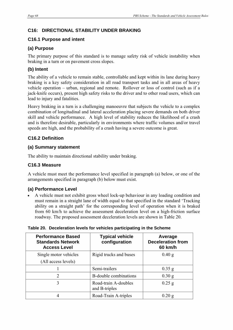
Page 68 PBS Scheme - The Standards and Vehicle Assessment Rules
C16: DIRECTIONAL STABILITY UNDER BRAKING
C16.1 Purpose and intent
(a) Purpose The primary purpose of this standard is to manage safety risk of vehicle instability when braking in a turn or on pavement cross slopes.
(b) Intent The ability of a vehicle to remain stable, controllable and kept within its lane during heavy braking is a key safety consideration in all road transport tasks and in all areas of heavy vehicle operation – urban, regional and remote. Rollover or loss of control (such as if a jack-knife occurs), present high safety risks to the driver and to other road users, which can lead to injury and fatalities.
Heavy braking in a turn is a challenging manoeuvre that subjects the vehicle to a complex combination of longitudinal and lateral acceleration placing severe demands on both driver skill and vehicle performance. A high level of stability reduces the likelihood of a crash and is therefore desirable, particularly in environments where traffic volumes and/or travel speeds are high, and the probability of a crash having a severe outcome is great.
C16.2 Definition
(a) Summary statement
The ability to maintain directional stability under braking.
C16.3 Measure
A vehicle must meet the performance level specified in paragraph (a) below, or one of the arrangements specified in paragraph (b) below must exist.
(a) Performance Level • A vehicle must not exhibit gross wheel lock-up behaviour in any loading condition and
must remain in a straight lane of width equal to that specified in the standard ‘Tracking ability on a straight path’ for the corresponding level of operation when it is braked from 60 km/h to achieve the assessment deceleration level on a high-friction surface roadway. The proposed assessment deceleration levels are shown in Table 20.
Table 20. Deceleration levels for vehicles participating in the Scheme
Performance Based Standards Network
Access Level
Typical vehicle configuration
Average Deceleration from
60 km/h Single motor vehicles
(All access levels) Rigid trucks and buses 0.40 g
1 Semi-trailers 0.35 g 2 B-double combinations 0.30 g 3 Road-train A-doubles
and B-triples 0.25 g
4 Road-Train A-triples 0.20 g
PBS Scheme - The Standards and Vehicle Assessment Rules Page 69
• A vehicle (part) that relies upon an antilock brake system to comply with the standard must have automatic brake adjusters on each axle that are controlled by the anti-lock brake system.
• A (motor) vehicle that has an auxiliary brake system fitted that could produce an average deceleration of 0.1g or higher on the unladen (motor) vehicle must not be capable of applying automatically. This requirement is deemed to be met if the (motor) vehicle has an antilock brake system that both controls all the drive axle group wheels and has veto control over the auxiliary brakes.
• All parts of the (combination) vehicle must comply with the applicable Australian Design Rule for braking at the time of manufacture. If a load-proportion brake system is fitted it must comply with the unladen compatibility requirements in Australian Design Rule 35/02 (motor vehicles) or Australian Design Rule 38/03 (trailers). Concessions against the Australian Design Rule requirements in individual cases that have been agreed to by the Administrator of Motor Vehicle Standards are to be recognised when assessing compliance with this item.
Definitions:
The absence of gross wheel lock-up is defined as follows:
• Single and tandem axle groups do not exhibit sustained wheel lock-up on any axles at the assessment deceleration levels.
• Tri-axle and quad axle groups can exhibit sustained wheel lock-up on one axle only in the group at the assessment deceleration level.
• An axle group with more than four axles can exhibit wheel lock-up on any two axles in the group at the assessment deceleration level.
• Wheel lock-up that occurs on any wheel at speeds below 10 km/h can be ignored because the potential for a vehicle to deviate seriously from the preferred path is minor.
Axle groups are defined as follows:
• The axle-group definitions applicable to Australian Design Rules 35 and 38 are pertinent.
• The axles on a dolly trailer should be considered as forming one axle group.
(b) Deemed-to-comply provisions
Three deemed-to-comply arrangements are available as alternatives to independently finding means of meeting the proposed standard:
• a vehicle that has a functioning anti-lock brake system that effectively prevents gross wheel lock-up on each axle group (as defined in the definitions) is deemed to comply with the standard; or
• a motor vehicle in a combination vehicle that has a functioning anti-lock brake system that effectively prevents gross wheel lock-up behaviour on the motor vehicle, can be ignored when the test or simulation assessment is made. That is, the motor vehicle is deemed-to-comply and only the performance of the trailer(s) against the performance standard needs be addressed; or

Page 70 PBS Scheme - The Standards and Vehicle Assessment Rules
• a combination vehicle that has a load proportioning brake system on each part that has been set to meet the lightly laden compatibility limits in the pending revisions to Australian Design Rules 35 and 38 (Australian Design Rule 35/02 and 38/03) is deemed to comply with this standard. Note that a motor vehicle that has an antilock brake system as described in the preceding paragraph and trailer(s) that meet the lightly laden compatibility limits are deemed to comply with this standard.
C16.4 Test specifications
(a) Test load
The vehicle being assessed should be tested in the unladen condition. If the vehicle complies in the unladen condition, it is deemed to comply in the laden condition.
Each tyre on the vehicle must have a tread depth of at least 90% of the original value over the whole tread width and circumference of the tyre. Each tyre must be inflated to the pressure as specified by the vehicle and/or tyre manufacturer. The tread depth of each tyre must not decrease by more than 2 mm during field testing.
(b) Test conditions
The test site must have uniform, smooth, dry, hard pavement, which is free from contaminants. The surface must have a coefficient of friction value, μpeak, at the tyre/road contact surface of not more than 0.80.
(c) Test procedure
The test (initial) speed should be in the range 59 – 65 km/h. The point where deceleration starts and the point where the vehicle stops should be marked on the test roadway. The computed average deceleration is then:
Average deceleration = ½ (initial speed in m/s)2 / (g x stopping distance in m)
where g = 9.81 m/s2
The wheel lock-up behaviour can be assessed by video recording the wheels on each side of the vehicle. Temporary marking of the exposed tyre walls will assist in assessing whether the wheels are locked or not.
Acceptable test conditions exists when the average deceleration is at least equal to the applicable assessment deceleration level in Table 20.
(d) Test method
Numerical modelling or field-testing.
(e) Further notes
All parts of the (combination) vehicle must comply with the applicable Australian Design Rule for braking at the time of manufacture.
If a load-proportion brake system is fitted it must comply with the unladen compatibility requirements in Australian Design Rule 35/02 (motor vehicles) or Australian Design Rule 38/03 (trailers).

PBS Scheme - The Standards and Vehicle Assessment Rules Page 71
APPENDIX D: [RESERVED]

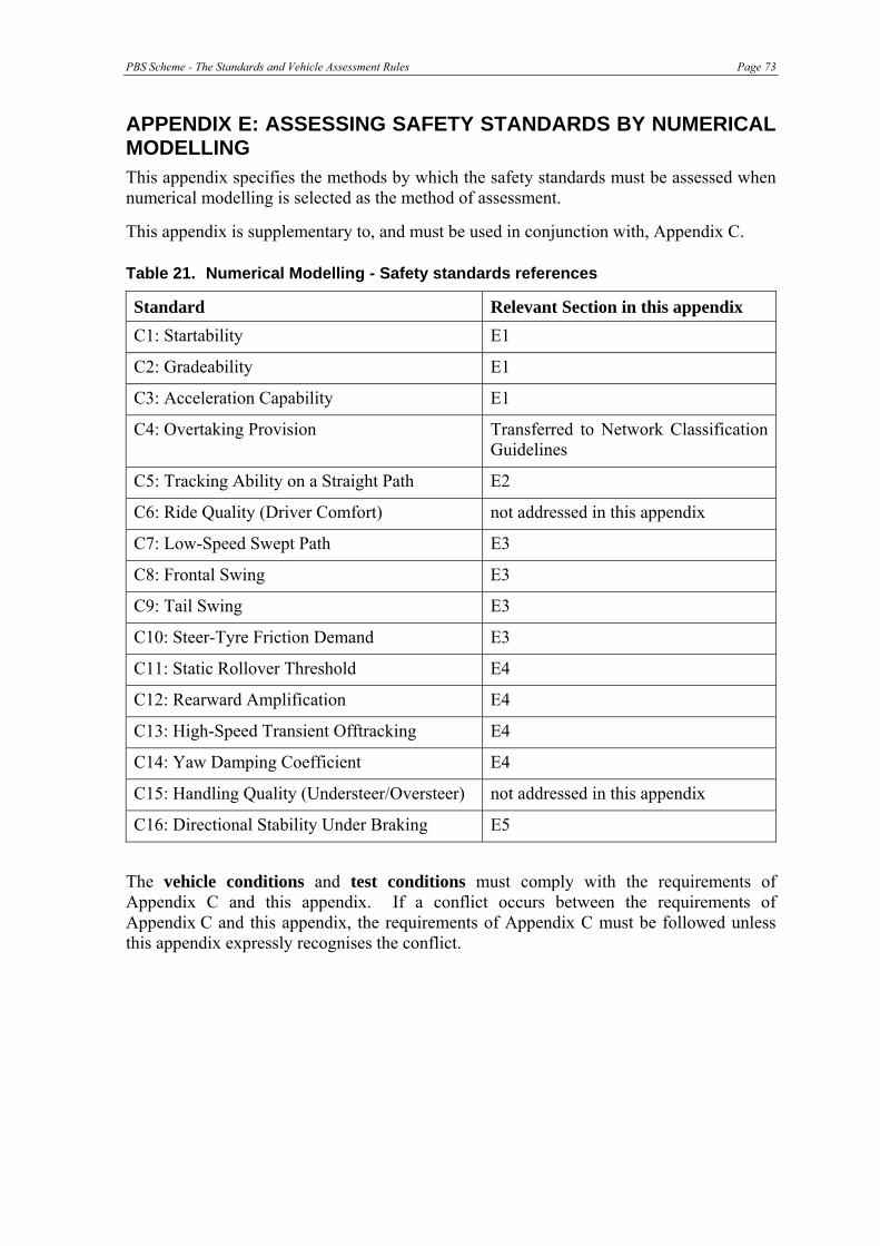
PBS Scheme - The Standards and Vehicle Assessment Rules Page 73
APPENDIX E: ASSESSING SAFETY STANDARDS BY NUMERICAL MODELLING This appendix specifies the methods by which the safety standards must be assessed when numerical modelling is selected as the method of assessment.
This appendix is supplementary to, and must be used in conjunction with, Appendix C.
Table 21. Numerical Modelling - Safety standards references
Standard Relevant Section in this appendix C1: Startability E1
C2: Gradeability E1
C3: Acceleration Capability E1
C4: Overtaking Provision Transferred to Network Classification Guidelines
C5: Tracking Ability on a Straight Path E2
C6: Ride Quality (Driver Comfort) not addressed in this appendix
C7: Low-Speed Swept Path E3
C8: Frontal Swing E3
C9: Tail Swing E3
C10: Steer-Tyre Friction Demand E3
C11: Static Rollover Threshold E4
C12: Rearward Amplification E4
C13: High-Speed Transient Offtracking E4
C14: Yaw Damping Coefficient E4
C15: Handling Quality (Understeer/Oversteer) not addressed in this appendix
C16: Directional Stability Under Braking E5
The vehicle conditions and test conditions must comply with the requirements of Appendix C and this appendix. If a conflict occurs between the requirements of Appendix C and this appendix, the requirements of Appendix C must be followed unless this appendix expressly recognises the conflict.
Page 74 PBS Scheme - The Standards and Vehicle Assessment Rules
E1: STARTABILITY, GRADEABILITY AND ACCELERATION CAPABILITY
E1.1 General
The three standards in this group, startability, gradeability and acceleration capacity, assess the ability of heavy vehicles to start on grade, climb on grade, and accelerate from rest and increase speed on level ground, respectively. These standards are inter-related because each primarily depends on engine and driveline characteristics. They can all be evaluated using the same data set for a specific vehicle or combination.
Each of the three standards addresses a different aspect of performance that is influenced by different areas of engine and driveline characteristics. Startability, for example, is influenced by clutch engagement torque and low gear operation, while gradeability, in addressing both low and high-gear (speed) operations, is not influenced by clutch engagement torque at low speeds. Acceleration capability, on the other hand, depends on engine characteristics and gearing across the entire speed range as well as other factors such as the timing, duration and strategy of gear changes. In addition to the above listed factors, rolling losses, aerodynamic drag, gross mass and the prevailing tyre/road friction limits will also influence performance.
E1.2. Model construction
(a) Principles
Numerical models must account for:
• gross combination mass; • engine power/torque-speed characteristics and any de-rating associated with ancillary
equipment (if applicable); • clutch engagement (manual transmission) or torque converter (automatic
transmission) considerations; • transmission and final drive reduction ratios and the influence of tyre size (rolling
radius) on net tractive effort; • the influence of inertia of rotating components; • losses due to grade resistance (if applicable); • losses due to rolling resistance; • losses due to aerodynamic drag; • time delays associated with gear shifting (manual or automatic transmissions); and • limitations in performance due to tyre/road friction considerations, that is, if the
tractive effort exceeds the available tyre/road friction limits then performance will be friction limited.
(b) Explanation
(i) Grade
Grade changes a vehicle’s orientation with respect to gravity so that:
• The normal force exerted by the tyres on the road surface is reduced in comparison with the zero-grade condition, in turn reducing the available friction at the driven axles and the tyre rolling resistance at all axles.
PBS Scheme - The Standards and Vehicle Assessment Rules Page 75
• A down-the-grade component acts to resist forward motion on an upgrade and to aid forward motion on a downgrade.
• The vector sum of the normal and down-the-grade forces is equal to the total weight of the vehicle or combination when the vehicle is in equilibrium.
(ii) Drive axle traction
Drive axle traction must be considered as a function of:
• Normal force exerted by each driven axle on the pavement at the specified grade.
• Distribution of engine torque to the driven axles.
• Rolling radius of the tyre and any changes that occur with changes in tyre normal load.
• Prevailing tyre/road friction coefficient.
(iii) Mass moments of inertia
• The mass moment of inertia of the rotating components in the driveline induces a resisting inertia force in response to angular acceleration.
• The mass moment of inertia of the road wheels induces a resisting inertia force in response to the angular acceleration of the road wheels.
(iv) Tyre rolling resistance
Tyre rolling resistance induce a resisting force on the system, which is a function of tyre normal force, speed and road surface unevenness.
(v) Aerodynamic drag
Aerodynamic drag can be calculated according to the equation:
SVCD D2
21 ρ=
where D = Aerodynamic drag (N)
CD = Aerodynamic drag coefficient (-)
ρ = Air density at sea level or a specified altitude (kg/m3)
V = Forward velocity (m/s)
S = Frontal area (m2)
(vi) Engine torque-speed curve
The engine torque should be considered as a function of engine speed.
(vii) Engine speed range
The engine should operate within a speed range specified by the manufacturer.
(viii) Clutch engagement torque
At forward speeds less than that at which minimum engine speed is achieved in the starting gear ratio, a manufacturer-specified clutch engagement torque must be applied.
Page 76 PBS Scheme - The Standards and Vehicle Assessment Rules
(ix) Gear ratios
The ratios incorporated in the transmission and in the driven axles must be considered.
(x) Driveline mechanical efficiency
Mechanical losses must be incorporated into the driveline, such that the torque delivered to the driven axles is less than that calculated from the engine torque and transmission gear ratios.
(xi) Gear changes
When the engine reaches the upper or lower limit of its speed range, an algorithm for selecting a more suitable gear must be applied. This algorithm must consider the time required to change gears (the gear change time must be no less than 1.5 sec).
E1.3 Input data sets
Gross mass: Maximum gross mass of vehicle.
Engine: Engine power/torque versus engine speed curves and de-rating associated with ancillary equipment, i.e. net engine torque.
Clutch/converter: Clutch engagement torque or torque converter multiplier factors (stall torque ratio and stall speed).
Transmission: Gear reduction ratios (and rotational inertias).
Final drive: Reduction ratio (and rotational inertias).
Wheels: Rolling radius at specified wheel load (and rotational inertia).
Losses: Rolling resistance and aerodynamic drag.
Gear shift: Time delays associated with gear shift, and gear shift sequencing if other than sequential.
Road Surface: Friction coefficient as specified in the test procedure (Appendix C).
E1.4 Model verification
In accordance with the requirements of Attachment A to Appendix E.
E1.5 Simulation model application
The following is one method of performing startability and gradeability simulations.
For startability and gradeability: The simulation should first be attempted on an upgrade appropriate to the road classification level, having a whole-number value when expressed in percent. If the first simulation is successful, it should be repeated on an upgrade which is 1% greater than the previously tested upgrade. This process should be repeated until the first failure is encountered. If the first simulation is unsuccessful, it should be repeated on an upgrade which is 1% less than the previously tested upgrade. This process should be repeated until the first success is encountered. The greatest upgrade on which a successful test is simulated must be reported as the performance of the vehicle.
For acceleration capacity: In accordance with Appendix C.

PBS Scheme - The Standards and Vehicle Assessment Rules Page 77
E1.6 Simulation model output
According to the requirements of Appendix C.
E1.7 Sensitivity testing
In accordance with the requirements of Division 4 of Part 2.
E1.8 Reporting
In accordance with the requirements of Attachment B to Appendix E and with Appendix G.

Page 78 PBS Scheme - The Standards and Vehicle Assessment Rules
E2 TRACKING ABILITY ON A STRAIGHT PATH
E2.1 General
The “tracking ability on a straight path” standard measures the ability of the trailing units in the combination vehicle, or rear of a single-unit vehicle, to faithfully track along the same path as the front of the vehicle. The standard effectively establishes the vehicle’s lane width requirement when travelling along a straight path in the presence of roadway disturbances (unevenness and cross slope) and driver steer activity. To evaluate performance the vehicle must traverse a road segment of the specified length, unevenness and cross slope at the specified travel speed.
E2.2 Model construction
(a) Principles
The ability of the trailing units in a combination vehicle, or rear of a single-unit vehicle, to faithfully track along the same path as the front of the vehicle depends on a range of vehicle-related factors, including:
• number of trailers and the location and type of coupling between them (turntable or pintle hitch);
• wheelbase dimensions; • mass properties; • alignment of axles; • suspension geometry (roll and bump steer effects); • tyre cornering stiffness; • vehicle length; and • speed.
Tracking ability performance will also depend on vehicle width, front and rear overhang dimensions, and plan view details of the outside corners of the front and rearmost vehicle units. External disturbances imposed on the system by road surface unevenness, cross slope, and driver steer activity, are the main sources of excitation causing the rearmost part of the vehicle to deviate from the path of the front of the vehicle when travelling along a straight path.
(b) Explanation
i) Topology
There are various ways of constructing models. One method is to separately represent the motions of each rigid body of the vehicle or combination. In this context, a rigid body is any part that is either defined as a rigid part, or alternatively, one that is subject to significant motion (in translation and/or rotation) in relation to the other parts in the system. The precise method of defining parts, either rigid or flexible, will depend on the specific modelling techniques employed. Where structural deflections may have a significant effect on the behaviour of the vehicle, flexibility should be considered in the construction of the model.
Examples of more common rigid bodies are:
• the combination of a trailer chassis and everything rigidly attached to it, including the body and the restrained payload, but not the axles, hubs, wheels and tyres; and
PBS Scheme - The Standards and Vehicle Assessment Rules Page 79
• the combination of an axle and the parts that are rigidly attached to it. This may include the hubs, wheels and tyres, but the hubs, wheels and tyres could be treated as separate rigid parts that rotate in relation to the axle.
Examples of less common rigid bodies are:
• a link in a specialised trailer steering or coupling system; and
• a translating or rotating sub-frame in a specialised trailer steering system.
A rigid body may be classified as either sprung, unsprung or auxiliary, dependent upon its location in the system.
ii) Mass properties
Mass properties may or may not be assigned to each part of the simulation model, and will depend on how the model has been constructed. Parts which have been assigned a mass will generally have the following properties:
• Mass;
• moments of inertia;
• centre-of-gravity location; and
iii) Coupling properties
Vehicle couplings, such as fifth-wheels, pin-couplings and ball-couplings, typically inter-connect the sprung parts of a vehicle. They are generally represented with the appropriate articulation degrees of freedom. Any resistance offered by the couplings, such as fifth-wheel overturning resistance, should be represented with an appropriate level of compliance.
iv) Suspension properties
Suspensions typically connect the unsprung parts of a vehicle (axles) to the sprung parts of a vehicle (chassis). Suspension properties maybe represented as defined below:
• Bounce degree of freedom – if appropriate, relative vertical movement must be possible between the axle and the chassis, such as that which occurs when the vehicle travels over a bump.
• Roll degree of freedom – if appropriate, relative roll movement must be possible between the axle and chassis, such as that which occurs when the vehicle travels around a bend at speed. The roll degree of freedom must be configured such that the axis of roll motion passes through the suspension roll centre and is inclined to induce suspension roll-steer. Suspension roll properties can differ considerably within an axle group, so the model needs to be capable of representing different roll properties within an axle group.
• Vertical stiffness and damping–if bounce and roll degrees of freedom exist, vertical force elements must be applied between the axle and chassis to control the bounce and roll degrees of freedom by way of stiffness and damping in a manner that is representative of the vehicle design.
• Auxiliary roll stiffness - If a roll degree of freedom exists, a moment may need to be applied in addition to that provided by vertical stiffness, because the roll stiffness

Page 80 PBS Scheme - The Standards and Vehicle Assessment Rules
generated by vertical stiffness may not represent the total roll stiffness of the suspension. Total roll stiffness includes such effects as torsion in suspension components.
v) Tyre properties
Tyre properties must include at least the following (with reference to Society of Automotive Engineers20):
• Vertical stiffness – the stiffness that causes normal force to vary with tyre compression.
• Lateral force characteristics in the free-rolling condition – the characteristics that define lateral force as a function of normal force and lateral slip angle.
• Aligning torque characteristics – the characteristics that define aligning torque as a function of normal force and lateral slip angle.
Forces and moments must be applied to the tyre such that their line of action is normal to the road surface at the point of contact. The orientation of the road surface must vary as a function of the road crossfall and the longitudinal road profile.
vi) Driver properties
The simulation model must be steered by the steering tyres of the vehicle via a control system with parameters that can be modified to achieve the desired steering performance.
E2.3 Input data sets
(a) Geometric properties
The following parameters define the minimum set of dimensions that must be represented in the model:
• Major units – detailed geometric descriptions of each of the major units, particularly features that influence the specified path trajectories.
• Wheelbases – the overall distance between centrelines of the steer axle or axle group, and the drive axle or axle group, on a rigid truck, bus/coach or prime mover. The overall distance between the forward coupling point and the centreline of the axle or axle group on a semi-trailer, converter dolly or pig/tag trailer. In all cases, wheelbase dimensions must be measured either to single axles, or to the centreline of the axle group, located midway between the centrelines of the outermost axles of the group. If the group consists of two axles, one of which is fitted with twice the number of tyres as the other axle, the centre of the axle group is the line located one-third of the way from the centreline of the axle with more tyres towards the centreline of the axle with fewer tyres. If the group contains self-steer axles, the centreline of the axle group is taken to be the centreline of the non-steered axles in the group. Force or command-steer axles are treated the same as non-steered axles.
• Axle group spread – distances between the centrelines of axles within a group.
• Track width – width related dimensions are measured from the centre of an axle to the wheel centreline or suspension element centreline. For tyres, these dimensions locate
20 Society of Automotive Engineers (1976). Vehicle Dynamics Terminology. SAE Recommended Practice J670e, Society of Automotive Engineers: Warrendale, PA, United States of America.
PBS Scheme - The Standards and Vehicle Assessment Rules Page 81
either the centrelines of single tyres, such as on steering axles, or the centre of the dual tyre pair with an accompanying dual spacing dimension.
• Longitudinal location of couplings – the longitudinal location of each coupling element, typically either turntables (fifth wheel couplings) or pin-type couplings is specified in terms of distances from the centreline of either a single axle or axle group.
• Height of couplings – the vertical location of couplings is specified in terms of the height above the ground. For turntables the vertical location of the coupling is the height of the coupler face and skid plate above the ground. For pin couplings the vertical location of the coupling is the height of the centre of the drawbar eye, or equivalent joint centre, above the ground.
(b) Mass properties
The following parameters define the minimum set of mass properties that must be used in the model:
• Sprung and unsprung masses – sprung and unsprung masses21 of each major vehicle unit for the laden state.
• Centre of gravity locations – longitudinal locations of sprung and unsprung mass centre of gravities of each major vehicle unit for the laden state. If the vehicle or its load is not symmetric then lateral locations of centre of gravities must be specified.
• Mass moments of inertia – these must be defined about a set of orthogonal axles, consistent with the Society of Automotive Engineers co-ordinate system (Society of Automotive Engineers , 1976), whose origin is located at the component centre of gravity.
(c) Couplings
The following parameters define the minimum set of characteristics of couplings that must be represented in the model:
• Turntable couplings – vehicle units connected through turntable couplings must be constrained in such a way that they cannot translate relative to each other but can rotate relative to each other in roll, pitch and yaw22. Further, the constraints imposed on the joint must provide little or no resistance to rotations in pitch and yaw. Rotation about the roll axis must be resisted by either a linear or non-linear rotational spring element whose mechanical properties (roll moment versus angular deflection) are largely consistent with the roll characteristics of a turntable coupling.
• Pin couplings – vehicle units connected through a pin coupling must be constrained in such a way that there is no translation of one unit with respect to the other unit at the point of connection. The coupling constraint must provide little or no resistance to rotational motion with the units free to rotate relative to each other about all three axes (roll, pitch and yaw).
21 As defined in Society of Automotive Engineers (1976)
22 Rotation angles are defined in Society of Automotive Engineers (1976)

Page 82 PBS Scheme - The Standards and Vehicle Assessment Rules
• Other – couplings that are not turntable or pin couplings must be modelled in a way that largely reproduces the main mechanical properties of the physical component.
(d) Suspensions
The minimum requirement for suspension components that must be defined in the model are the following mechanical properties measured at each axle:
• Composite vertical stiffness – The most fundamental property of all suspensions is vertical stiffness provided by the spring elements. When the entire suspension deflects in the vertical direction from its nominal static position, all the spring elements deflect in unison and their individual stiffness’s sum to the determine the composite vertical stiffness, Kv, of the suspension as follows:
∑==s
zv
KZF
K (1)
This equation shows that composite vertical stiffness (Kv) is defined as the vertical force (Ks) required per unit of vertical deflection (Z) and is composed of the sum of the stiffness’s of all the springs of the suspensions (ΣKs).
Most heavy commercial vehicles use either multi-leaf steel springs or air springs (airbag). Steel torsion bars or rubber elements may also be used to provide the spring action. Multi-leaf steel springs display a complex force/displacement relationship which includes friction as well as stiffness qualities. The stiffness of air springs is generally strongly dependent on vertical load.
Other suspension springs must be modelled in a way that largely reproduces the main mechanical properties of the physical component.
• Composite roll stiffness – When the sprung mass rolls relative to the unsprung mass (referred to as suspension roll), the suspension springs on each side of the vehicle deflect in opposite directions to produce a restoring overturning moment. The relationship between suspension roll angle and restoring moment is known as the composite roll stiffness of the suspension. Composite roll stiffness depends on individual spring rates and the lateral spring spacing, plus any auxiliary roll stiffness, as follows:
aux
ss
s
xr
KT
KM
K +⎟⎟⎠
⎞⎜⎜⎝
⎛==
2
22
φ (2)
This equation shows that composite roll stiffness (Kr) is the roll moment (Mx) per degree of suspension roll angle (Φs) and derives from the spring stiffness (Ks) times the square of one half of the lateral spring spacing (Ts) plus any auxiliary roll stiffness (Kaux).
Multi-leaf steel spring suspensions usually have a small amount of auxiliary roll stiffness, produced as the springs are twisted along their length in order for the axle to roll. By contrast, air suspensions, which generally have low vertical stiffness, usually require an auxiliary roll stiffness device, either in the form of an anti-sway bar, or the trailing arm is rigidly clamped to the axle so that the whole assembly acts as an anti-sway bar.
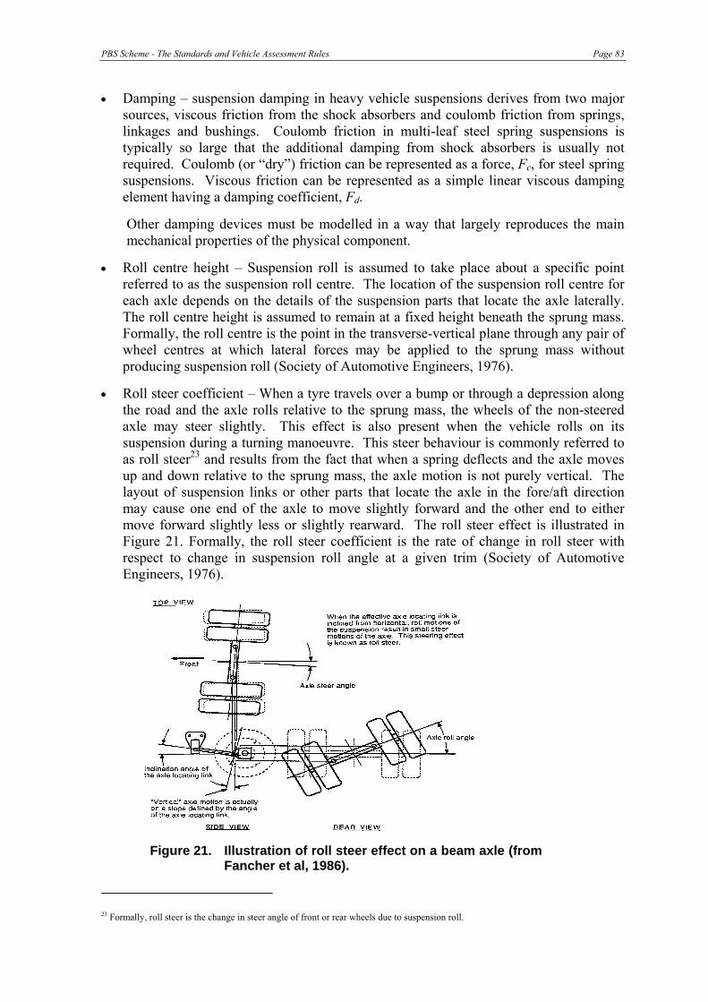
PBS Scheme - The Standards and Vehicle Assessment Rules Page 83
• Damping – suspension damping in heavy vehicle suspensions derives from two major sources, viscous friction from the shock absorbers and coulomb friction from springs, linkages and bushings. Coulomb friction in multi-leaf steel spring suspensions is typically so large that the additional damping from shock absorbers is usually not required. Coulomb (or “dry”) friction can be represented as a force, Fc, for steel spring suspensions. Viscous friction can be represented as a simple linear viscous damping element having a damping coefficient, Fd.
Other damping devices must be modelled in a way that largely reproduces the main mechanical properties of the physical component.
• Roll centre height – Suspension roll is assumed to take place about a specific point referred to as the suspension roll centre. The location of the suspension roll centre for each axle depends on the details of the suspension parts that locate the axle laterally. The roll centre height is assumed to remain at a fixed height beneath the sprung mass. Formally, the roll centre is the point in the transverse-vertical plane through any pair of wheel centres at which lateral forces may be applied to the sprung mass without producing suspension roll (Society of Automotive Engineers, 1976).
• Roll steer coefficient – When a tyre travels over a bump or through a depression along the road and the axle rolls relative to the sprung mass, the wheels of the non-steered axle may steer slightly. This effect is also present when the vehicle rolls on its suspension during a turning manoeuvre. This steer behaviour is commonly referred to as roll steer23 and results from the fact that when a spring deflects and the axle moves up and down relative to the sprung mass, the axle motion is not purely vertical. The layout of suspension links or other parts that locate the axle in the fore/aft direction may cause one end of the axle to move slightly forward and the other end to either move forward slightly less or slightly rearward. The roll steer effect is illustrated in Figure 21. Formally, the roll steer coefficient is the rate of change in roll steer with respect to change in suspension roll angle at a given trim (Society of Automotive Engineers, 1976).
Figure 21. Illustration of roll steer effect on a beam axle (from
Fancher et al, 1986).
23 Formally, roll steer is the change in steer angle of front or rear wheels due to suspension roll.

Page 84 PBS Scheme - The Standards and Vehicle Assessment Rules
(e) Tyres
All the forces needed to both support and guide a vehicle ultimately arise in the area of contact between the tyre and the roadway. These forces are generated at the road surface in response to deformation of the tyre structure. Vertical forces arise in response to vertical deflection of the tyre structure, cornering forces that are developed to control the vehicle, change direction, and resist sideways disturbances are produced in response to lateral slip (slip angle) and/or inclination of the tyre to the road surface (camber angle), and forces in the longitudinal direction for acceleration or braking are generated by longitudinal slip.
The tyre model must feature, or be capable of producing, the following external forces on the tyre by the road:
• Normal Force: A vertical force normal to the road surface. The relationship between vertical force exerted by the road on the tyre and tyre deflection. In its basic form the tyre vertical load-deflection relationship is expressed conveniently by tyre vertical stiffness:
ZF
k zt= (3)
This equation shows that the tyre vertical stiffness (kt) is defined as the vertical force (Kz) required per unit of vertical deflection (Z).
• Lateral Force: The relationship between lateral or side force (Fy) exerted by the road on the tyre and sideslip or slip angle (α), and the influence of vertical load (Fz) on the relationship. For a typical truck tyre the relationship is illustrated in Figure 22.
Figure 22. Side force characteristics of an 11R22.5 size truck tyre
showing the influence of tyre vertical load.

PBS Scheme - The Standards and Vehicle Assessment Rules Page 85
• Aligning Moment: A moment in the road plane exerted on the tyre by the road that aligns the wheel plane with the direction of travel. The relationship between aligning moment (Mz) exerted by the road on the tyre and sideslip or slip angle (α) and the influence of vertical load (Fz) on the relationship. For a typical truck tyre the relationship is illustrated in Figure 23.
Figure 23. Aligning moment characteristics of an 11R22.5 size truck
tyre showing the influence of tyre vertical load.
(f) Propulsion
Forward speed is one of the greatest influences on the majority of the standards. The model must feature a means of maintaining a constant forward speed. There are several methods of propelling the vehicle model to maintain forward velocity that can be used. The model can either be propelled by:
• the application of tractive effort to the tyres;
• the longitudinal degree-of-freedom can be removed from the model and the forward velocity of the lead or towing unit constrained mathematically such that its speed is constant during the manoeuvre; or
• the application of an external force to the chassis.
(g) Steer control
Directional control of the model is achieved through the steer controller. Depending on the manoeuvre, steer control is intended to accomplish either a specific, precisely defined sequence of steer angle input, or it will guide the vehicle along a prescribed path approximating the same way that a real driver would steer the vehicle along a path. These activities are conveniently separated into the following two distinct forms of control, namely, open-loop control and closed-loop control.
• Open-loop control: This form of control is used for the purposes of characterising only vehicle response. In an open-loop control sequence the input steer is defined precisely and must be applied exactly as specified.

Page 86 PBS Scheme - The Standards and Vehicle Assessment Rules
• Closed-loop control: In this form of control a desired vehicle motion or trajectory is achieved, such as following a precisely prescribed path – either a straight path or one that is complex such as a lane change – by continuously monitoring vehicle response (longitudinal and lateral position in the lane change example cited) and adjusting steering actions accordingly. In closed-loop control the driver is actively involved in the control process throughout the manoeuvre. In a closed-loop system the driver is considered an integral part of the system to the extent that in the numerical model the equations of motion for the entire system are actually modified.
The steering controller must produce representative steering activity largely consistent with the performance of actual drivers in a demanding straight-path tracking task in the presence of external disturbances (road surface unevenness). This means steer frequencies in the range 0.1 to 0.9 Hz must be present, and the lateral displacement of a point at the centre of the forward-most steer-axle must have a root-mean-square (r.m.s) value of not less than 25 millimetres. The steer frequency requirement referred to above is achieved when the contribution to the total mean square value of steer angle (measured at the road wheels) from steer activity in the frequency range 0.1 to 0.9 Hz is not less than 60% (Prem, Mai and McLean, 2005).
(h) Road profiles and surface friction
For standards such as “Tracking ability on a straight path” the wheel path road profiles provide part of the external disturbances to the numerical model through the tyre contact areas. However, most simulated manoeuvres in Performance Based Standards are performed on perfectly smooth surfaces and do not require a specific set of road profiles.
Surface friction values are specified in Appendix C.
E2.4 Model verification
In accordance with the requirements of Attachment A to Appendix E.
E2.5 Simulation model application
In accordance with Appendix C and this section.
The simulation model must be initialised to reach steady-state before entering the 1,000 m test section as an unsettled manner will result in erroneous results.
E2.6 Simulation model output
According to the requirements of Appendix C.
E2.7 Sensitivity testing
In accordance with the requirements of Division 4 of Part 2.
E2.8 Reporting
In accordance with the requirements of Attachment B to Appendix E and with Appendix G.

PBS Scheme - The Standards and Vehicle Assessment Rules Page 87
E3 LOW SPEED SWEPT PATH, FRONTAL SWING, TAIL SWING AND STEER TYRE FRICTION DEMAND
E3.1 General
The performance levels for the standards of low-speed swept path, frontal swing and tail swing are determined from the path trajectories of specified points on the vehicle. The performance level in the fourth standard (steer tyre friction demand) is determined from the horizontal and vertical tyre forces at the steer tyres under the specified tyre/road friction conditions.
E3.2 Model construction
(a) Principles
Heavy vehicle offtracking in a low-speed small-radius turn primarily depends upon:
• lead unit wheelbase; • coupling locations; and • the lengths between articulation points and axle locations.
This dependence varies in accordance with the squares of the (trailer/semi-trailer) lengths for a particular vehicle, and the longest trailer wheelbase is a critical parameter in determining the level of offtracking. Axle group loads and tyre properties have an important influence; maximum offtracking occurs when a vehicle operates at low axle loads on tyres that have high cornering stiffness. A number of software packages are commonly used to estimate low speed swept width. However, most ignore tyre mechanics and not all of these packages could satisfy all of the requirements of Appendix C.
Additionally, low-speed swept path, frontal swing and tail swing performance will depend on vehicle width, front and rear overhang dimensions, and plan view details of the outside corners of vehicle major units (truck, bus/coach or prime mover, in particular).
Steer tyre friction demand is largely a function of hauling unit wheelbase and drive axle-group spread. For steer tyre friction demand, steering must be effected by the steer tyres (should be applied to all measures except low-speed longitudinal and low-speed directional).
(b) Explanation
As specified in Section E2.2.
E3.3 Input data sets
As specified in Section E2.3.
E3.4 Model verification
In accordance with the requirements of Attachment A to Appendix E.
E3.5 Simulation model application
According to the requirements of Appendix C.
Care must be taken to ensure that the trajectory of the point of maximum offtracking on the inside of the turn is computed. This point will be in a different position on every vehicle. Further, it moves with the vehicle and during the turn it may move on the vehicle relative

Page 88 PBS Scheme - The Standards and Vehicle Assessment Rules
to its initial location. Particular care must be taken with vehicles that have command-steer systems on trailing units to ensure the point of maximum offtracking is correctly located throughout the turn.
E3.6 Simulation model output
According to the requirements of Appendix C.
E3.7 Sensitivity testing
In accordance with the requirements of Division 4 of Part 2. However, the value of sensitivity testing will depend on the features contained in the numerical model. For example, models based purely on geometry will not be responsive to changes in tyre loads and must only be used as preliminary indicators of performance level.
E3.8 Reporting
In accordance with the requirements of Attachment B to Appendix E and with Appendix G.
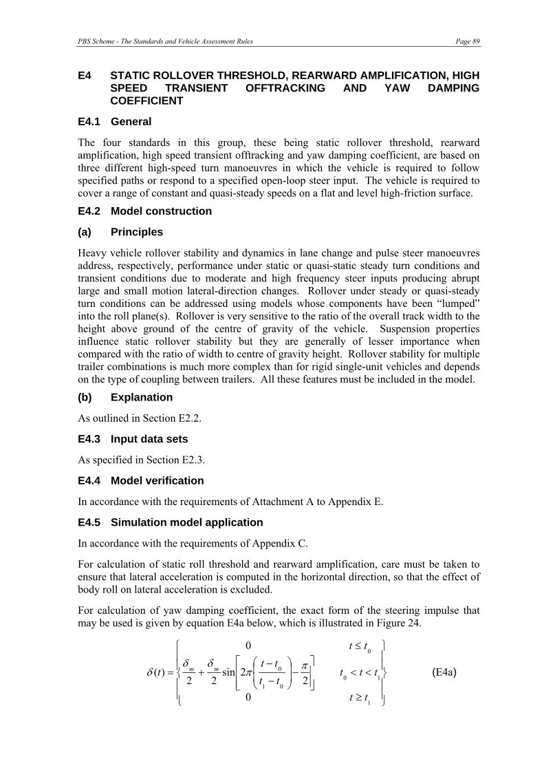
PBS Scheme - The Standards and Vehicle Assessment Rules Page 89
E4 STATIC ROLLOVER THRESHOLD, REARWARD AMPLIFICATION, HIGH SPEED TRANSIENT OFFTRACKING AND YAW DAMPING COEFFICIENT
E4.1 General
The four standards in this group, these being static rollover threshold, rearward amplification, high speed transient offtracking and yaw damping coefficient, are based on three different high-speed turn manoeuvres in which the vehicle is required to follow specified paths or respond to a specified open-loop steer input. The vehicle is required to cover a range of constant and quasi-steady speeds on a flat and level high-friction surface.
E4.2 Model construction
(a) Principles
Heavy vehicle rollover stability and dynamics in lane change and pulse steer manoeuvres address, respectively, performance under static or quasi-static steady turn conditions and transient conditions due to moderate and high frequency steer inputs producing abrupt large and small motion lateral-direction changes. Rollover under steady or quasi-steady turn conditions can be addressed using models whose components have been “lumped” into the roll plane(s). Rollover is very sensitive to the ratio of the overall track width to the height above ground of the centre of gravity of the vehicle. Suspension properties influence static rollover stability but they are generally of lesser importance when compared with the ratio of width to centre of gravity height. Rollover stability for multiple trailer combinations is much more complex than for rigid single-unit vehicles and depends on the type of coupling between trailers. All these features must be included in the model.
(b) Explanation
As outlined in Section E2.2.
E4.3 Input data sets
As specified in Section E2.3.
E4.4 Model verification
In accordance with the requirements of Attachment A to Appendix E.
E4.5 Simulation model application
In accordance with the requirements of Appendix C.
For calculation of static roll threshold and rearward amplification, care must be taken to ensure that lateral acceleration is computed in the horizontal direction, so that the effect of body roll on lateral acceleration is excluded.
For calculation of yaw damping coefficient, the exact form of the steering impulse that may be used is given by equation E4a below, which is illustrated in Figure 24.
⎪⎪
⎭
⎪⎪
⎬
⎫
⎪⎪
⎩
⎪⎪
⎨
⎧
≥
<<⎥⎥⎦
⎤
⎢⎢⎣
⎡−⎟
⎟⎠
⎞⎜⎜⎝
⎛
−
−+
≤
=
1
1001
0
0
02
2sin22
0
)(
tt
ttttttt
tt
t mm ππδδ
δ (E4a)

Page 90 PBS Scheme - The Standards and Vehicle Assessment Rules
where:
t = time (s) t0 = commencement of pulse steer application (s) t1 = termination of pulse steer application (s) δ = steer angle (deg) δm = amplitude of steer angle pulse (peak value)(deg)
The following alternative equation, which is equivalent to equation E4a, may also be used:
⎪⎪
⎭
⎪⎪
⎬
⎫
⎪⎪
⎩
⎪⎪
⎨
⎧
≥
<<⎥⎥⎦
⎤
⎢⎢⎣
⎡⎟⎟⎠
⎞⎜⎜⎝
⎛
−
−−
≤
=
1
1001
0
0
0
2cos22
0
)(
tt
ttttttt
tt
t mm πδδ
δ (E4b)
Either equation E4a or equation E4b must be used.
Figure 24. Exact form of the pulse steer input given by equation E4a.
E4.6 Simulation model output
In accordance with the requirements of Appendix C.
E4.7 Sensitivity testing
In accordance with the requirements of Division 4 of Part 2.
E4.8 Reporting
In accordance with the requirements of Attachment B to Appendix E and with Appendix G.
PBS Scheme - The Standards and Vehicle Assessment Rules Page 91
E5 DIRECTIONAL STABILITY UNDER BRAKING
E5.1 General
When demonstrated by simulation, a compliant vehicle must not have an instantaneous Friction Utilisation value on any axle group that exceeds 0.7 for any instantaneous vehicle deceleration up to and including the assessment deceleration levels given in Table 20.
(a) Principles
The Friction Utilisation of an axle group is defined as:
Utilisation = total axle group retardation forces at the pavement / total axle group weight
where the summations are over all the axles in the group. (E5a)
The definition of an axle group is as given in C16(d).
The simulation algorithm should use foundation brake models that are based upon the certification status or other justifiable test performance of the actual vehicle brake types. For example, the brake torque model can be based upon the average torque data for trailer axles that have Subassembly Reference Numbers (SARNs) which are available on the Department of Transport and Regional Service’s web site.
The road surface can be assumed to have a high friction coefficient exceeding 0.7 and hence wheel lock-up behaviour need not be simulated.
The simulation should account for load transfers between axle groups however, dynamic load distribution changes between axles in each group need not be simulated.
The axle group weight to be used in equation (E5a) is the dynamic level that is affected by weight transfer at the simulation deceleration level.
An approach to computation of the friction utilisation is illustrated in Figure 25. The purpose of the computation is to compute the friction utilisation ratios for the axle groups U1, U2, U3 at the assessment deceleration levels specified in the standard.
(b) Explanation
An acceptable computation approach involves the following aspects:
• The brake application pressure at each axle is computed using the known air control valve static characteristics and the selected brake control level.
• At the selected brake control level, the brake torque at each axle is computed.
• The axle retardation forces are computed using the known tyre radius and the axle torques (T1-T6 in Figure 25).
• An average tyre radius for each group can be used. The tyre radius should be varied depending upon the dynamic load carried by the axle group.
• An allowance should be made for engine drag, aerodynamic drag and tyre loss force. This adds to vehicle retardation force. The engine drag force for example adds the drive axle group force F2 in Figure 25. There is also a tyre loss force that contributes to F1-F6 (Figure 25) and should be modelled.

Page 92 PBS Scheme - The Standards and Vehicle Assessment Rules
• The instantaneous deceleration is calculated using the known vehicle weight and the total computed retardation forces.
• The weight carried by each axle is calculated using the known static weights and the deceleration level. Load transfers between axle groups are computed using basic physics.
• The friction utilisation on each axle group is calculated using the known weight force ΣWaxle and the computed retardation force ΣFaxle.
• The simulation should be started at low brake levels and stepped up until the instantaneous deceleration level of the vehicle equals or exceeds the assessment deceleration level stated in Table 20.
• At each instantaneous deceleration level the friction utilisation of each axle group must be less than 0.7.
(c) Acceptable simplifying assumptions
This simulation procedure can apply the following simplifying assumptions:
• Instantaneous axle torque values can be based on average torque levels established from stopping tests or dynamometer tests.
• It is impractical to compute the friction utilisation of individual axles within an axle group because the load proportioning behaviour of the axle group suspension is generally unknown. Hence only the axle group friction utilisation should be considered.
• The rolling resistance retardation force of the tyres can be assumed to be 0.0015 x weight carried for a driven axle and 0.0010 x weight carried for a non-driven axle (see ECE R13V9, Annex 13, Appendix 2 Cl. 1.1.4.)
Figure 25. Idealised brake forces acting on a semi-trailer.

PBS Scheme - The Standards and Vehicle Assessment Rules Page 93
E5.2 Model verification
In accordance with the requirements of Attachment A to Appendix E.
E5.3 Simulation model output
In accordance with the requirements of Appendix C.
E5.4 Sensitivity testing
In accordance with the requirements of Division 4 of Part 2.
E5.5 Reporting
In accordance with the requirements of Attachment B to Appendix E and with Appendix G.


PBS Scheme - The Standards and Vehicle Assessment Rules Page 95
ATTACHMENT A TO APPENDIX E
Model validation and verification
If component level performance data or mechanical properties are obtained, either from component suppliers/manufacturers or by direct measurement, it is essential that the performance of the modelled component be specified over the entire operating range that will be used in the model of the vehicle being assessed in the prescribed manoeuvres. This check is necessary to ensure the performance boundaries of the component model are not exceeded in the simulation. If component level performance data or mechanical properties are estimated by calculation, these must be able to be verified.
The extent of physical testing should reflect the degree of risk associated with the proposal. Where the design being assessed is very similar to an existing prescriptive vehicle or vehicle participating in the Scheme, physical testing may only need to be conducted through on-road performance monitoring. This approach can be used to provide validation of numerical models.
Definitions
• Validate: To compare measurements from a test of a physical system with outputs from a numerical simulation of the test, showing that the numerical model adequately represents the physical system under those conditions.
• Verify: To warrant that the modelling principles of a validated numerical model are suitable for the construction of numerical models applied to similar systems under similar conditions.

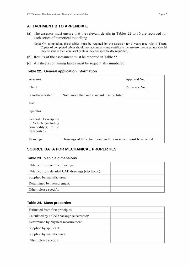
PBS Scheme - The Standards and Vehicle Assessment Rules Page 97
ATTACHMENT B TO APPENDIX E
(a) The assessor must ensure that the relevant details in Tables 22 to 36 are recorded for each series of numerical modelling. Note: On completion, these tables must be retained by the assessor for 5 years (see rule 11(1)(a)).
Copies of completed tables should not accompany any certificate the assessor prepares, nor should they be sent to the Secretariat (unless they are specifically requested).
(b) Results of the assessment must be reported in Table 55.
(c) All sheets containing tables must be sequentially numbered.
Table 22. General application information
Assessor: Approval No.
Client: Reference No.
Standard/s tested: Note: more than one standard may be listed
Date:
Operator:
General Description of Vehicle (including commodity(s) to be transported):
Drawings: Drawings of the vehicle used in the assessment must be attached
SOURCE DATA FOR MECHANICAL PROPERTIES
Table 23. Vehicle dimensions
Obtained from outline drawings:
Obtained from detailed CAD drawings (electronic):
Supplied by manufacturer:
Determined by measurement:
Other, please specify:
Table 24. Mass properties
Estimated from first principles:
Calculated by a CAD package (electronic):
Determined by physical measurement:
Supplied by applicant:
Supplied by manufacturer:
Other, please specify:

Page 98 PBS Scheme - The Standards and Vehicle Assessment Rules
Table 25. Suspensions
Estimated from first principles:
Determined by physical measurement:
Supplied by applicant:
Supplied by manufacturer:
Other, please specify:
Table 26. Tyres
Determined by calculation:
Determined by physical measurement:
Supplied by applicant:
Supplied by manufacturer:
Other, please specify:
Table 27. Chassis properties (flexible)
Determined by calculation:
Determined by physical measurement:
Supplied by applicant:
Supplied by manufacturer:
Other, please specify:
Table 28. Powertrain
Supplied by manufacturer:
Determined by measurement:
Other, please specify:
NUMERICAL MODELS – Tables 29 to 34 must be completed for each separate model that is used in the assessment.
Table 29. Standards assessed with models described in Tables 30 to 34
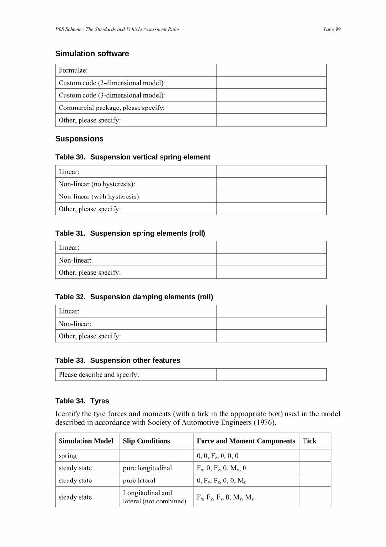
PBS Scheme - The Standards and Vehicle Assessment Rules Page 99
Simulation software
Formulae:
Custom code (2-dimensional model):
Custom code (3-dimensional model):
Commercial package, please specify:
Other, please specify:
Suspensions
Table 30. Suspension vertical spring element
Linear:
Non-linear (no hysteresis):
Non-linear (with hysteresis):
Other, please specify:
Table 31. Suspension spring elements (roll)
Linear:
Non-linear:
Other, please specify:
Table 32. Suspension damping elements (roll)
Linear:
Non-linear:
Other, please specify:
Table 33. Suspension other features
Please describe and specify:
Table 34. Tyres
Identify the tyre forces and moments (with a tick in the appropriate box) used in the model described in accordance with Society of Automotive Engineers (1976).
Simulation Model Slip Conditions Force and Moment Components Tick
spring 0, 0, Fz, 0, 0, 0
steady state pure longitudinal Fx, 0, Fz, 0, My, 0
steady state pure lateral 0, Fy, Fz, 0, 0, Mz
steady state Longitudinal and lateral (not combined) Fx, Fy, Fz, 0, My, Mz
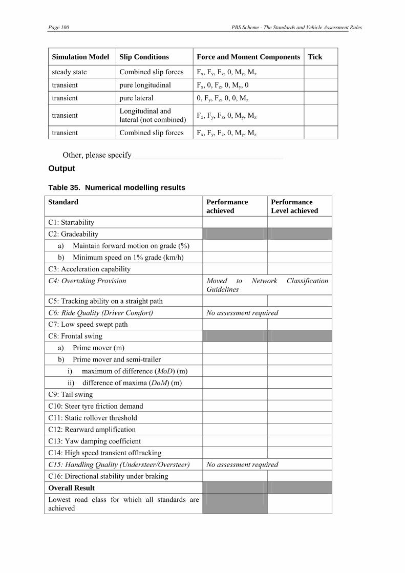
Page 100 PBS Scheme - The Standards and Vehicle Assessment Rules
Simulation Model Slip Conditions Force and Moment Components Tick
steady state Combined slip forces Fx, Fy, Fz, 0, My, Mz
transient pure longitudinal Fx, 0, Fz, 0, My, 0
transient pure lateral 0, Fy, Fz, 0, 0, Mz
transient Longitudinal and lateral (not combined) Fx, Fy, Fz, 0, My, Mz
transient Combined slip forces Fx, Fy, Fz, 0, My, Mz
Other, please specify_____________________________________
Output
Table 35. Numerical modelling results
Standard Performance achieved
Performance Level achieved
C1: Startability C2: Gradeability
a) Maintain forward motion on grade (%) b) Minimum speed on 1% grade (km/h)
C3: Acceleration capability C4: Overtaking Provision Moved to Network Classification
Guidelines C5: Tracking ability on a straight path C6: Ride Quality (Driver Comfort) No assessment required C7: Low speed swept path C8: Frontal swing
a) Prime mover (m) b) Prime mover and semi-trailer
i) maximum of difference (MoD) (m) ii) difference of maxima (DoM) (m)
C9: Tail swing C10: Steer tyre friction demand C11: Static rollover threshold C12: Rearward amplification C13: Yaw damping coefficient C14: High speed transient offtracking C15: Handling Quality (Understeer/Oversteer) No assessment required
C16: Directional stability under braking
Overall Result Lowest road class for which all standards are achieved
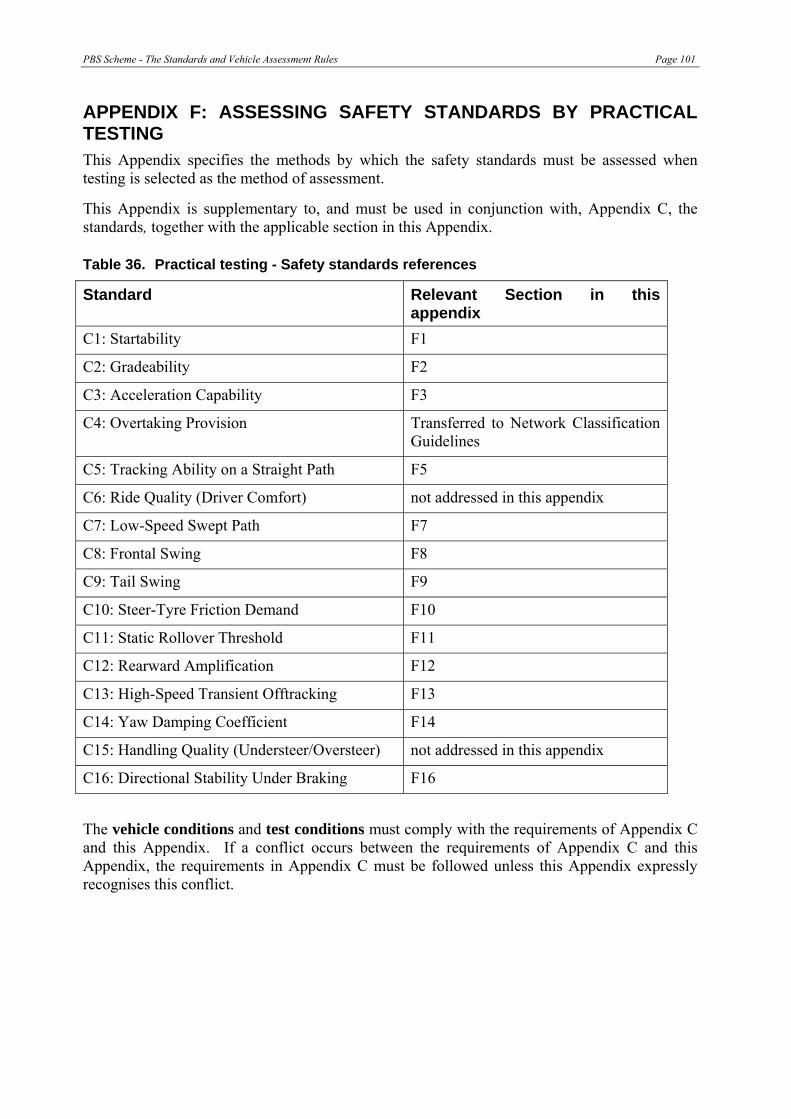
PBS Scheme - The Standards and Vehicle Assessment Rules Page 101
APPENDIX F: ASSESSING SAFETY STANDARDS BY PRACTICAL TESTING This Appendix specifies the methods by which the safety standards must be assessed when testing is selected as the method of assessment.
This Appendix is supplementary to, and must be used in conjunction with, Appendix C, the standards, together with the applicable section in this Appendix.
Table 36. Practical testing - Safety standards references
Standard Relevant Section in this appendix
C1: Startability F1
C2: Gradeability F2
C3: Acceleration Capability F3
C4: Overtaking Provision Transferred to Network Classification Guidelines
C5: Tracking Ability on a Straight Path F5
C6: Ride Quality (Driver Comfort) not addressed in this appendix
C7: Low-Speed Swept Path F7
C8: Frontal Swing F8
C9: Tail Swing F9
C10: Steer-Tyre Friction Demand F10
C11: Static Rollover Threshold F11
C12: Rearward Amplification F12
C13: High-Speed Transient Offtracking F13
C14: Yaw Damping Coefficient F14
C15: Handling Quality (Understeer/Oversteer) not addressed in this appendix
C16: Directional Stability Under Braking F16
The vehicle conditions and test conditions must comply with the requirements of Appendix C and this Appendix. If a conflict occurs between the requirements of Appendix C and this Appendix, the requirements in Appendix C must be followed unless this Appendix expressly recognises this conflict.

Page 102 PBS Scheme - The Standards and Vehicle Assessment Rules
F1. STARTABILITY
F1.1 Vehicle conditions Vehicle conditions must comply with the requirements of Appendix C and Attachment A.
F1.2 Test conditions Test conditions must comply with the requirements of Section C1.4 (b) of Appendix C, and with Attachment B.
F1.3 Data acquisition None.
F1.4 Data processing None.
F1.5 Test procedure Vehicle position markings
The following three positions must be marked on the test site prior to execution of the test. These are listed in order of increasing elevation on the grade:
• Initial position of the rear most axle (rear mark)
• Initial position of the front axle (start mark)
• Target position of the front axle (finish mark)
The rear mark and the start mark must be spaced according to the dimensions of the extreme axles. The start mark and the finish mark must be spaced 5 metres apart longitudinally.
The vehicle must be placed with its front axle at the start mark and its rear axle at the rear mark. The service brakes must be engaged and a suitable gear ratio selected.
The driver must release the service brakes and drive the vehicle forward at constant or increasing speed until the front axle passes the finish mark.
The test may be performed at one or more test sites and may be attempted one or more times at each test site.
F1.6 Reporting
The following items must be reported:
i) all test, vehicle and site details in Attachment E.
ii) the road profile (plot of elevation versus distance) for the driver and passenger wheel paths.
iii) the grade profile (percentage grade versus distance) for the driver and passenger wheel paths, and the grade profile of the point-by-point average of the driver and passenger wheel path profiles.
PBS Scheme - The Standards and Vehicle Assessment Rules Page 103
iv) maximum and minimum grade values (driver and passenger wheel paths, and average) in accordance with the grade specification defined in Section C1.4 (b) of Appendix C.
F1.7 Safety The test site must be safe for all personnel, including but not limited to those conducting and observing the test and the general public. The site manager must follow the safety requirements outlined in Attachment D.

Page 104 PBS Scheme - The Standards and Vehicle Assessment Rules
F2. GRADEABILITY
F2.1 Vehicle conditions Vehicle conditions must comply with the requirements of Appendix C and Attachment A.
F2.2 Test conditions Test conditions must comply with the requirements of Appendix C and with Attachment B.
F2.3 Data acquisition Data acquisition requirements, including anti-aliasing filtering and bandwidth requirements, are specified in Section 3.1 of SAE J2181.
Instrumentation to acquire vehicle performance data must meet the requirements detailed in Table 1 of SAE J2181.
F2.4 Data processing None.
F2.5 Test procedure As defined in Appendix C.
F2.6 Reporting All test, vehicle and site details in Attachment E must be reported.
For the standard “maintain motion”, the grade of the test length must be reported.
For the standard “maintain speed”, the following items must be reported:
i) the maximum speed at which the vehicle satisfied the requirements of Appendix C;
ii) the road profile (plot of elevation versus distance) for the driver and passenger wheel paths.
iii) the grade profile (percentage grade versus distance) for the driver and passenger wheel paths, and the grade profile of the point-by-point average of the driver and passenger wheel paths profiles.
iv) Maximum and minimum grade values (driver and passenger wheel paths, and average) in accordance with the grade specification defined in Section C2.7 (b) of Appendix C.
F2.7 Safety The test site must be safe for all personnel, including but not limited to those conducting and observing the test and the general public. The site manager must follow the safety requirements outlined in Attachment D.
PBS Scheme - The Standards and Vehicle Assessment Rules Page 105
F3. ACCELERATION CAPABILITY
F3.1 Vehicle conditions Vehicle conditions must comply with the requirements of Appendix C and Attachment A.
F3.2 Test conditions Test conditions must comply with the requirements of Section 3.4(b) of Appendix C (except for grade) and with Attachment B. Appendix C states:
The full length of the vehicle must be on a site with zero grade throughout the test.
With field testing, if a zero grade site is not available, it is acceptable to average the results of two runs in opposite directions over a test length that does not have a zero grade, even if the grade varies.
F3.3 Data acquisition Data acquisition requirements including anti-aliasing filtering and bandwidth requirements are specified in Section 3.1 of SAE J2181.
Instrumentation to acquire vehicle performance data must meet the requirements detailed in the Table 1 of SAE J2181.
F3.4 Data processing Assessors must prepare the distance versus time data to be presented as defined in Appendix C3.3.
F3.5 Test procedure As defined in Appendix C. In order to minimise the influence of grade on the performance results during a field test, at least two valid test runs must be conducted on the same section of pavement, one run in each travel direction. The results from an equal number of runs in each direction must be averaged and reported as the achieved performance.
F3.6 Reporting The following must be reported:
i) all test, vehicle and site details in Attachment E;
ii) the time taken to travel 100 metres;
iii) the road profile (plot of elevation versus distance) for the driver and passenger wheel paths;
iv) the grade profile (percentage grade versus distance) for the driver and passenger wheel paths, and the grade profile of the point-by-point average of the driver and passenger wheel path profiles;
v) maximum and minimum grade values (driver and passenger wheel paths, and average) in accordance with the grade specification defined in Section C3.4 (b) of Appendix C;

Page 106 PBS Scheme - The Standards and Vehicle Assessment Rules
F3.7 Safety The test site must be safe for all personnel, including but not limited to those conducting and observing the test and the general public. The site manager must follow the safety requirements outlined in Attachment D.
F4. [RESERVED]
F5. TRACKING ABILITY ON A STRAIGHT PATH
F5.1 Vehicle conditions Vehicle conditions must comply with the requirements of Appendix C and Attachment A.
F5.2 Test conditions Test conditions must comply with the requirements of Appendix C and with Attachment B.
F5.3 Data acquisition Data acquisition and processing must be conducted as outlined in ISO 14791:2000(E) Sections 5.1, 5.2 and 5.3. Instrumentation to acquire vehicle performance data must meet these requirements.
Table 37. Tracking ability instrumentation requirements
Variable Typical operating range Combined system error
Swept width (m) 0 to 3.5 * 0.05
Longitudinal distance (m) 0 to 2,000 0.1
* this is the overall swept width and assessors may use different techniques which many not include the vehicle width in the measurement
F5.4 Data processing Data processing must be undertaken as outlined in ISO 14791:2000(E) section 5.3.
Compute the vehicle swept width for each valid run. Completion of a test in accordance with the test procedure and method of Appendix C constitutes a valid run.
F5.5 Test procedure As defined in Appendix C.
Three valid runs must be completed.
F5.6 Reporting The following must be reported for each of three valid runs:
i) all test, vehicle and site details in Attachment E;

PBS Scheme - The Standards and Vehicle Assessment Rules Page 107
ii) swept width value expressed as a 99th percentile value;
iii) vehicle swept width time (or distance) history over the test length;
iv) road-wheel steer angle time (or distance) history over the test length;
v) maximum, minimum and average vehicle speeds over the test length;
vi) road-wheel steer angle expressed as the root-mean-square (RMS) over the test length;
vii) steer angle expressed as an autospectral density function (temporal);
viii) the road profile (plot of elevation versus distance) for the driver and passenger wheel paths;
ix) the IRI values reported every 100 metres the percentage grade profiles (percentage grade versus distance) for the driver and passenger wheel paths, and the grade profile of the point-by-point average of the driver and passenger wheel path profiles;
x) maximum and minimum grade values (driver and passenger wheel paths, and average) in accordance with the grade specification defined in Section C5.4 (b) of Appendix C; and
xi) the percentage crossfall profiles (percentage crossfall versus distance), average and standard deviation of the crossfall.
F5.7 Safety The test site must be safe for all personnel, including but not limited to those conducting and observing the test and the general public. The site manager must follow the safety requirements outlined in Attachment D.
F6. RIDE QUALITY (DRIVER COMFORT)
This standard is not covered in this Appendix at this time. See section C6.2.
F7. LOW-SPEED SWEPT PATH
F7.1 Vehicle conditions Vehicle conditions must comply with the requirements of Appendix C and Attachment A.
F7.2 Test conditions Test conditions must comply with the requirements of Appendix C and with Attachment B.
F7.3 Data acquisition Data acquisition requirements including anti-aliasing filtering and bandwidth requirements are specified in Section 3.1 of SAE J2181. Instrumentation requirements are specified in Table 1 of SAE J2181 and instruments to acquire vehicle performance data must meet the following requirements.

Page 108 PBS Scheme - The Standards and Vehicle Assessment Rules
Table 38. Low speed swept path instrumentation requirements
Variable Typical operating range Combined system error
Swept path (m) 0 to 15 0.05
Path following error of the steer tyre (m)
0 to 0.1 0.02
* this is the overall swept path and assessors may use different techniques which may not included the vehicle width in the measurement.
(a) Swept path
Measurement of the swept path must use either road-based or vehicle-based methods or a combination of both.
(b) Tyre path
Measurement of the tyre path must be referenced against a marked path on the road surface which the driver must follow as specified in Appendix C.
The test is validated by the measurement of the tyre path reference as defined in Appendix C. The tyre path reference point must be located on the vehicle as defined in Appendix C.
F7.4 Data processing Data processing must be undertaken as defined in Appendix C figure 6.
F7.5 Test procedure As defined in Appendix C.
F7.6 Reporting The following must be reported:
i) all test, vehicle and site details in Attachment E;
ii) inner and outer path trajectories of the swept path envelope as defined in Appendix C;
iii) maximum width of the swept path as defined in Appendix C; and
iv) maximum deviation from the prescribed path.
F7.7 Safety The test site must be safe for all personnel, including but not limited to those conducting and observing the test and the general public. The site manager must follow the safety requirements outlined in Attachment D.

PBS Scheme - The Standards and Vehicle Assessment Rules Page 109
F8. FRONTAL SWING
F8.1 Vehicle conditions Vehicle conditions must comply with the requirements of Appendix C and Attachment A.
F8.2 Test conditions Test conditions must comply with the requirements of Appendix C and with Attachment B.
F8.3 Data acquisition Data acquisition requirements including anti-aliasing filtering and bandwidth requirements are specified in Section 3.1 of SAE J2181.
If transducers are used to measure frontal swing requirements as defined in Part A, Part B and Part C in Appendix C they must be located within 150 mm of the extremity of the vehicle being assessed and appropriate corrections must be made for the location of these transducers during data processing. Instrumentation to acquire vehicle performance data must meet the following requirements.
Table 39. Frontal swing instrumentation requirements
Variable Typical operating range Combined system error
Frontal swing (m) 0 to 1 0.05
Path following error of the steer tyre (m)
0 to 0.1 0.02
(a) Tyre path
Measurement of the tyre path must be referenced against a marked path on the road surface which the driver is to follow as defined in Appendix C.
The test must be validated by the measurement of the tyre path reference as defined in Appendix C. The tyre path reference point must be located on the vehicle as defined in Appendix C.
F8.4 Data processing Data processing must be undertaken as defined in Appendix C8.6, Figures 9, 10, 11 and 12.
F8.5 Test procedure As defined in Appendix C.
F8.6 Reporting The following must be reported:
i) all test, vehicle and site details in Attachment E;
ii) maximum frontal swing A;
iii) maximum frontal swing B;

Page 110 PBS Scheme - The Standards and Vehicle Assessment Rules
iv) maximum frontal swing C; and
v) maximum deviation from the prescribed path.
F8.7 Safety The test site must be safe for all personnel, including but not limited to those conducting and observing the test and the general public. The site manager must follow the safety requirements outlined in Attachment D.

PBS Scheme - The Standards and Vehicle Assessment Rules Page 111
F9. TAIL SWING
F9.1 Vehicle conditions Vehicle conditions must comply with the requirements of Appendix C and Attachment A.
F9.2 Test conditions Test conditions must comply with the requirements of Appendix C and with Attachment B.
F9.3 Data acquisition Data acquisition requirements including anti-aliasing filtering and bandwidth requirements are specified in Section 3.1 of SAE J2181.
If transducers are used to measure frontal swing requirements as defined in Part A, Part B and Part C in Appendix C they must be located within 150 mm of the extremity of the vehicle being assessed and appropriate corrections must be made for the location of these transducers during data processing. Instrumentation to acquire vehicle performance data must meet the following requirements.
Table 40. Tail swing instrumentation requirements
Variable Typical operating range Combined system error
Tail swing (m) 0 to 0.5 0.02
Path following error of the steer tyre (m)
0 to 0.1 0.02
(a) Tyre path
Measurement of the tyre path must be referenced against a marked path on the road surface which the driver must follow as defined in Appendix C.
The test must be validated by the measurement of the tyre path reference as defined in Appendix C. The tyre path reference point must be located on the vehicle as defined in Appendix C.
F9.4 Data processing Data processing must undertaken be as defined in Appendix C9 Figure 13.
F9.5 Test procedure As defined in Appendix C.
F9.6 Reporting The following must be reported:
i) all test, vehicle and site details in Attachment E;
ii) tail swing path trajectories as defined in Appendix C; and
iii) tail swing.

Page 112 PBS Scheme - The Standards and Vehicle Assessment Rules
iv) maximum deviation from the prescribed path.
F9.7 Safety The test site must be safe for all personnel, including but not limited to those conducting and observing the test and the general public. The site manager must follow the safety requirements outlined in Attachment D.
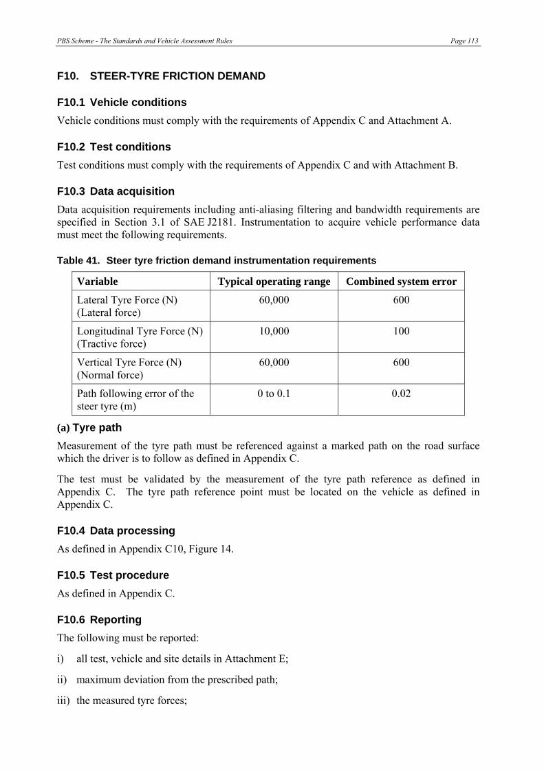
PBS Scheme - The Standards and Vehicle Assessment Rules Page 113
F10. STEER-TYRE FRICTION DEMAND
F10.1 Vehicle conditions Vehicle conditions must comply with the requirements of Appendix C and Attachment A.
F10.2 Test conditions Test conditions must comply with the requirements of Appendix C and with Attachment B.
F10.3 Data acquisition Data acquisition requirements including anti-aliasing filtering and bandwidth requirements are specified in Section 3.1 of SAE J2181. Instrumentation to acquire vehicle performance data must meet the following requirements.
Table 41. Steer tyre friction demand instrumentation requirements
Variable Typical operating range Combined system error
Lateral Tyre Force (N) (Lateral force)
60,000 600
Longitudinal Tyre Force (N) (Tractive force)
10,000 100
Vertical Tyre Force (N) (Normal force)
60,000 600
Path following error of the steer tyre (m)
0 to 0.1 0.02
(a) Tyre path Measurement of the tyre path must be referenced against a marked path on the road surface which the driver is to follow as defined in Appendix C.
The test must be validated by the measurement of the tyre path reference as defined in Appendix C. The tyre path reference point must be located on the vehicle as defined in Appendix C.
F10.4 Data processing As defined in Appendix C10, Figure 14.
F10.5 Test procedure As defined in Appendix C.
F10.6 Reporting The following must be reported:
i) all test, vehicle and site details in Attachment E;
ii) maximum deviation from the prescribed path;
iii) the measured tyre forces;

Page 114 PBS Scheme - The Standards and Vehicle Assessment Rules
iv) the steer-tyre friction demand as a function of time; and
v) maximum steer tyre friction demand.
F10.7 Safety The test site must be safe for all personnel, including but not limited to those conducting and observing the test and the general public. The site manager must follow the safety requirements outlined in Attachment D of this appendix.

PBS Scheme - The Standards and Vehicle Assessment Rules Page 115
F11. STATIC ROLLOVER THRESHOLD
F11.1 Vehicle conditions Vehicle conditions must comply with the requirements of Appendix C and Attachment A.
The vehicle being assessed must be loaded as outlined in ISO 14791:2000(E) section 6.4 and the axle masses recorded in accordance with Attachment E.
F11.2 Test conditions Test conditions must comply with the requirements of Appendix C and with Attachment B.
If the constant radius method is used, the test site must comply with the specifications in SAE J2181 section 4. The radius of the test must be not less than 100 metres.
If the tilt table method is used, the tilt table must comply with the specifications in SAE J2180 section 4, Table 1.
F11.3 Data acquisition Data acquisition requirements including anti-aliasing filtering and bandwidth requirements are specified in Section 3.1 of SAE J2181.
Constant radius method: The data acquisition and processing must be conducted as outlined in Section 4, Table 1 of SAE J2181.
Tilt table method: The tilt angle of the table must be measured to an accuracy of ±0.1 deg as outlined in Section 4 of SAE J2180.
F11.4 Data processing If the constant radius method, data processing must be conducted as outlined in Section 7 of SAE J2181 and as defined in Appendix C11.3.
If the tilt table method is used, data processing must be conducted as outlined in SAE J2180 section 5.
F11.5 Test procedure If the constant radius method is used, as outlined in SAE J2181 section 6.2, the vehicle must be driven at a constant road speed and data recorded once the vehicle has achieved steady-state cornering. The test must be repeated, in both clockwise and counter clockwise directions at a higher speed up to the point of rollover instability (defined in Appendix C), increasing either:
• in equal to or less than 2 km/h increments up to the speed when wheel lift occurs; or
• at a rate measured over any 5 second period not greater than 0.5 km/h per second.
If the tilt table method is used, the test procedure as outlined in SAE J2180 section 4 must be used.
F11.6 Reporting The following items must be reported:
i) all test, vehicle and site details in Attachment E; and
Page 116 PBS Scheme - The Standards and Vehicle Assessment Rules
ii) Appendix C section 11.3 (c) for constant radius method or SAE J2180 section 5 for tilt table method.
F11.7 Safety The test site must be safe for all personnel, including but not limited to those conducting and observing the test and the general public. The site manager must follow the safety requirements outlined in Attachment D.
Since the objective of these tests is to determine the rollover threshold of a vehicle or vehicle combination, the risk of rollover during testing is high.
Engineering-based methods (such as computer simulation) should be used to estimate the stability limit of the vehicle and the maximum manoeuvre severity which may be safely applied. Tests should progressively increase in severity and test data should be compared with the initial estimate of stability limit. The maximum manoeuvre severity should be adjusted as required, and this should be a prime safety management parameter for the testing.
Rollover protection: For the constant radius testing an outrigger system should be designed and fitted to the vehicle at appropriate locations to prevent rollover. Any outrigger should not restrict vehicle performance until beyond the rollover threshold. The extent to which the outrigger(s) affects the centre of mass must also be considered, and a reduction or redistribution of the load may be required to achieve the desired overall vehicle mass and centre of mass.
Vehicle restraint: For tilt table tests a vehicle security system should be employed to restrain the vehicle when wheel lift-off has been reached. Any vehicle security system should not restrict vehicle performance until beyond the rollover threshold.

PBS Scheme - The Standards and Vehicle Assessment Rules Page 117
F12. REARWARD AMPLIFICATION
F12.1 Vehicle conditions Vehicle conditions must comply with the requirements of Appendix C and Attachment A.
The vehicle being assessed must be loaded as outlined in ISO 14791:2000(E) section 6.4 and the axle masses recorded in accordance with Attachment E.
Tyres fitted to the vehicle must be in accordance with ISO 14791:2000(E) section 6.2, with tread depth measurements as detailed in Attachment A.
F12.2 Test conditions Test conditions must comply with the requirements of Appendix C and with Attachment B.
Despite the requirements of Appendix C, if a test track is selected that does not conform to the requirements of ISO 14791, the tests must be carried out in both directions if either the grade or crossfall of the test track is greater than 1%. If testing in both directions is not possible, testing should be carried out under the least favourable conditions (e.g. down grade and down crossfall for all manoeuvres if the grade is more than 1%).
The test site must comply with the specifications in ISO 14791:2000(E) section 6.1. The layout of the test course is shown in ISO 14791:2000(E) Figure 2.
The pavement surface characteristics of the test length must be measured and reported.
F12.3 Data acquisition The data acquisition must be conducted as outlined in Sections 5.1, 5.2 and 5.3 of ISO 14791:2000(E) except that transducers for measuring lateral acceleration on the first unit must be installed on the axle (unsprung mass).
F12.4 Data processing Data processing must be conducted as outlined in ISO 14791:2000(E) section 5.3, and as defined in Appendix C12.3.
F12.5 Test procedure The test must be conducted as described in ISO 14791:2000(E) sections 7.1, 7.2, 7.3 and 7.5 (single lane-change). Section 7.5.3 provides an equation to compute the test course coordinates for a given maximum lateral acceleration, steer input frequency and test speed.
The manoeuvre as described in Appendix C must be planned to provide a peak lateral acceleration of 0.15 g and a steer frequency equal to 0.40 Hz at a vehicle speed of 88 km/h. When field testing, it is recommended to not perform the test if the response of the last unit is likely to exceed 75% of the estimated rollover limit or 75% of any tyre friction limit unless suitable safety mechanisms are in place. Trial runs at lower severity (e.g. lower speed) are encouraged to predict the ability of the vehicle to safely complete the manoeuvre.

Page 118 PBS Scheme - The Standards and Vehicle Assessment Rules
F12.6 Reporting i) all test, vehicle and site details in Attachment E must be reported;
ii) data analysis and reporting must be conducted as described in ISO 14791:2000(E) sections 8.1 and 8.2.3; and
iii) the rearward amplification must be computed as outlined in Appendix C.
F12.7 Safety The test site must be safe for all personnel, including but not limited to those conducting and observing the test and the general public. The site manager must follow the safety requirements outlined in Attachment D.
This test is designed to induce lateral dynamics in the vehicle, so there is a risk that this test will produce vehicle responses that approach the rollover threshold. Therefore, steps should be taken to mitigate the rollover risk.
Engineering-based methods (such as computer simulation) should be used to estimate the stability limit of the vehicle and the maximum manoeuvre severity which may be safely applied. Tests should progressively increase in severity and test data should be compared with the initial estimate of stability limit. The maximum manoeuvre severity should be adjusted as required, and this should be a prime safety management parameter for the testing.
Outriggers, which are lateral extensions added to both sides of a vehicle unit to prevent it from rolling over, should be designed and fitted. Any outriggers must be adjusted to allow the unit to roll beyond its rollover threshold before touching the road surface and supplying a righting moment to prevent rollover.

PBS Scheme - The Standards and Vehicle Assessment Rules Page 119
F13. HIGH-SPEED TRANSIENT OFFTRACKING
F13.1 Vehicle conditions Vehicle conditions must comply with the requirements of Appendix C and Attachment A.
The vehicle being assessed must be loaded as outlined in ISO 14791:2000(E) section 6.4 and the axle masses recorded in accordance with Attachment E.
Tyres fitted to the vehicle must be in accordance with ISO 14791:2000(E) section 6.2, with tread depth measurements as detailed in Attachment A.
F13.2 Test conditions Test conditions must comply with the requirements of Appendix C and with Attachment B.
Despite the requirements of Appendix C, if a test track is selected that does not conform to the requirements of ISO 14791, the tests must be carried out in both directions if either the grade or crossfall of the test track is greater than 1%. If testing in both directions is not possible, testing should be carried out under the least favourable conditions (e.g. down grade and down crossfall for all manoeuvres if the grade is more than 1%).
The test site must comply with the specifications in ISO 14791:2000(E) section 6.1. The layout of the test course is shown in ISO 14791:2000(E) Figure 2.
The pavement surface characteristics of the test length must be measured and reported.
F13.3 Data acquisition Data acquisition must be conducted as outlined in sections 5.1, 5.2 and 5.3 of ISO 14791:2000 except that transducers for measuring lateral acceleration on the first unit must be installed on the axle (unsprung mass).
F13.4 Data processing Data processing must be conducted as outlined in ISO 14791:2000(E) section 5.3 and as defined in Appendix C13.3.
F13.5 Test procedure
The test must be conducted as outlined in ISO 14791:2000(E) sections 7.1, 7.2, 7.3 and 7.5 (single lane-change). Section 7.5.3 provides an equation to compute the test course coordinates for a given maximum lateral acceleration, steer input frequency and test speed.
F13.6 Reporting The following must be reported:
i) All test, vehicle and site details in Attachment E; and
ii) reporting as described in ISO 14791:2000(E) sections 8.1 and 8.3.
F13.7 Safety The test site must be safe for all personnel, including but not limited to those conducting and observing the test and the general public. The site manager must follow the safety requirements outlined in Attachment D.

Page 120 PBS Scheme - The Standards and Vehicle Assessment Rules
This test is designed to induce lateral dynamics in the vehicle, therefore there is a risk that this test will produce lateral activity near the rollover threshold and steps should be taken to mitigate the rollover risk.
Engineering-based methods (such as computer simulation) should be used to estimate the stability limit of the vehicle and the maximum manoeuvre severity which may be safely applied. Tests should progressively increase in severity and test data should be compared with the initial estimate of stability limit. The maximum manoeuvre severity should be adjusted as required, and this should be a prime safety management parameter for the testing.
Outriggers, which are lateral extensions added to both sides of a vehicle unit to prevent it from rolling over, should be designed and fitted. Any outriggers must be adjusted to allow the unit to roll beyond its rollover threshold before touching the road surface and supplying a righting moment to prevent rollover.
PBS Scheme - The Standards and Vehicle Assessment Rules Page 121
F14. YAW DAMPING COEFFICIENT
F14.1 Vehicle conditions Vehicle conditions must comply with the requirements of Appendix C and Attachment A.
The vehicle being assessed must be loaded as outlined in ISO 14791:2000(E) section 6.4 and the axle masses must be recorded in accordance with Attachment E.
Tyres fitted to the vehicle must be in accordance with ISO 14791:2000(E) section 6.2, with tread depth measurements as detailed in Attachment A.
F14.2 Test conditions Test conditions must comply with the requirements of Appendix C and with Attachment B.
Despite the requirements of Appendix C, if a test track is selected that does not conform to the requirements of ISO 14791, the tests must be carried out in both directions if either the grade or crossfall of the test track is greater than 1%. If testing in both directions is not possible, testing should be carried out under the least favourable conditions (e.g. down grade and down crossfall for all manoeuvres if the grade is more than 1%).
The test site must be selected as outlined in ISO 14791:2000(E) section 6.1. The layout of the test course is shown in ISO 14791:2000(E) Figure 2.
The pavement surface characteristics of the test length must be measured and reported.
F14.3 Data acquisition Data acquisition must be conducted as outlined in sections 5.1, 5.2 and 5.3 of ISO 14791:2000.
F14.4 Data processing Data processing must be conducted as outlined in ISO 14791:2000(E) section 5.3 and as defined in Appendix C14.3.
F14.5 Test procedure The test must be conducted as described in ISO 14791:2000(E) sections 7.6, 7.6.5.
F14.6 Reporting The following must be reported:
i) all test, vehicle and site details in Attachment E;
ii) reporting as described in ISO 14791:2000(E) sections 8.1, 8.4 and 8.4.1.
F14.7 Safety The test site must be safe for all personnel, including but not limited to those conducting and observing the test and the general public. The site manager must follow the safety requirements outlined in Attachment D.
This test is designed to induce lateral dynamics in the vehicle, therefore there is a risk that this test will produce lateral activity near the rollover threshold and steps should be taken to mitigate the rollover risk.
Page 122 PBS Scheme - The Standards and Vehicle Assessment Rules
Engineering-based methods (such as computer simulation) should be used to estimate the stability limit of the vehicle and the maximum manoeuvre severity which may be safely applied. Tests should progressively increase in severity and test data should be compared with the initial estimate of stability limit. The maximum manoeuvre severity should be adjusted as required, and this should be a prime safety management parameter for the testing.
Outriggers, which are lateral extensions added to both sides of a vehicle unit to prevent it from rolling over, should be designed and fitted. Any outriggers must be adjusted to allow the unit to roll beyond its rollover threshold before touching the road surface and supplying a righting moment to prevent rollover.
F15. HANDLING QUALITY (UNDERSTEER/OVERSTEER)
This standard is not covered in this appendix at this time. See section C15.2
F16. DIRECTIONAL STABILITY UNDER BRAKING
F16.1 Vehicle conditions Vehicle conditions must comply with the requirements of Appendix C and Attachment A.
F16.2 Test conditions Test conditions must comply with the requirements of Section C16.4 (b) of Appendix C, and with Attachment B.
F16.3 Data acquisition None.
F16.4 Data processing None.
F16.5 Test procedure The test procedure must comply with the requirements of Section C16.5 (c) of Appendix C, and with Attachment B.
F16.6 Reporting The following must be reported:
i) all test, vehicle and site details in Attachment E;
ii) average deceleration rate;
iii) identification and location of occurrence of any wheel lock up;
iv) stopping distance; and
v) vehicle position within lane during braking procedure.

PBS Scheme - The Standards and Vehicle Assessment Rules Page 123
F16.7 Safety The test site must be safe for all personnel, including but not limited to those conducting and observing the test and the general public. The site manager must follow the safety requirements outlined in Attachment D of this appendix.


PBS Scheme - The Standards and Vehicle Assessment Rules Page 125
ATTACHMENT A TO APPENDIX F – VEHICLE CONDITIONS
All vehicles must be in a roadworthy condition for the testing process.
Tyres fitted to the vehicle being assessed must be of the size and have the same specifications as used on the vehicle in practice. Inflation pressures must be set as recommended by the tyre manufacturer.
New tyres must be run-in for at least 200 kilometres.
The tread depth at a single point on the tyre that is representative of the overall tyre tread depth must be measured before and at the conclusion of the testing along with a visual inspection of each tyre. Each tyre must be measured for vehicles with less than 27 tyres. For vehicles with more than 27 tyres, the tyres that must be measured are:
• all tyres on the steer and drive groups;
• at least four tyres, selected at random, on each of the remaining axle groups.
The tread depth of any tyre measured must be not less than 90% of the tread depth when new.
The tyres and engine must be at operating temperatures prior to commencing the test.
The mass of the vehicle must be within the allowable variations set out in Austroads (2004), Table 1, Category 2.
In the case of road tankers designed to haul dangerous goods in bulk, the load must be substituted with a non-flammable and/or safe product that best replicates the load conditions of the vehicle being assessed in-service. The fill levels of all tank compartments must be recorded.
For unrestrained loads, load restraint must be sufficient for the levels of acceleration expected during testing.
Testing of vehicles loaded with livestock must comply with animal welfare legislation.
In the case of loose cargo, the load should be monitored during the test and any shifting, movement or non-typical behaviour must be documented. If any non-typical load shifting behaviour is observed the assessor must determine if this contributed to the vehicle failing to meet any relevant requirement.

PBS Scheme - The Standards and Vehicle Assessment Rules Page 127
ATTACHMENT B TO APPENDIX F – AMBIENT AND PAVEMENT CONDITIONS
The ambient air temperature at the test site must be within the range of 0ºC to 40ºC.
Ambient wind speed during testing must not exceed 5 m/s except that for a tilt table static rollover threshold test, testing should not be conducted when the wind speed exceeds 1.7 m/s.
The road surface must be free of loose material and be free of contamination at the time of the vehicle testing, and the surface must be dry.
Road profile measurements must be conducted with a World Bank (Sayers et al 1986) Class 1 device.
The International Roughness Index (IRI) values must be computed as outlined in Sayers et al (1986) and be reported at 100 metre intervals.
Acceptable pavement surface types for vehicle testing are: • concrete; • dense graded asphalt; • stone mastic asphalt; and • chip seal. If a chip seal or other surface is used it must be of adequate strength to not deteriorate during testing.

PBS Scheme - The Standards and Vehicle Assessment Rules Page 129
ATTACHMENT C TO APPENDIX F – DATA ACQUISITION
The vehicle performance data may be:
• vehicle-based; or
• road-based; or
• a combination of vehicle-based and road-based systems.
Data must be recorded against either a time-base or a distance-base.
If a combination of data recording techniques are used, there must be a common time-base or distance-base between the vehicle-based and road-based data acquisition systems.
Transducers, if used, must be firmly attached to the axles, the chassis or the vehicle body in a manner which avoids vibration transmitted from the vehicle.


PBS Scheme - The Standards and Vehicle Assessment Rules Page 131
ATTACHMENT D TO APPENDIX F – SAFETY
The test site manager is responsible for safety and must ensure that:
• a risk assessment is conducted of the field work as outlined in AS/NZS 4360:2004, and if the test is to be conducted on a public road then appropriate road closure and traffic control/management and a pilot vehicle are implemented in accordance with AS1742.3:2002.
• a “safe” and “keep clear” area(s) should be defined and clearly marked.
• no person must enter the “keep clear” area during execution of the test.
• no person must be in front of or behind the vehicle during the test manoeuvre and a safe distance between the vehicles must be maintained at all times as outlined in AS 1742.3:2002.
• audible warning or radio communication must be given to alert all personnel on site that the test has commenced.
• all personnel on site must be in contact with the site manager.
• all vehicle testing personnel must be trained in traffic management and fatigue management.
• a person trained with at least a certificate in Level II First Aid must be present at the site.
• all personnel present at the test site (including the driver) must sign a register requiring the information detailed in Table 53.
• all personnel must be briefed on the tasks, responsibilities and safety procedures.
• all personnel must wear suitable clothing and footwear as determined by the site manager.
• all high visibility safety garments must comply with AS/NZS 4602:1999.
• any driver of a vehicle under test must hold the licence appropriate to the vehicle being driven.
• the vehicle under test must not exceed the posted speed limit or any speed limits imposed on the vehicle type.

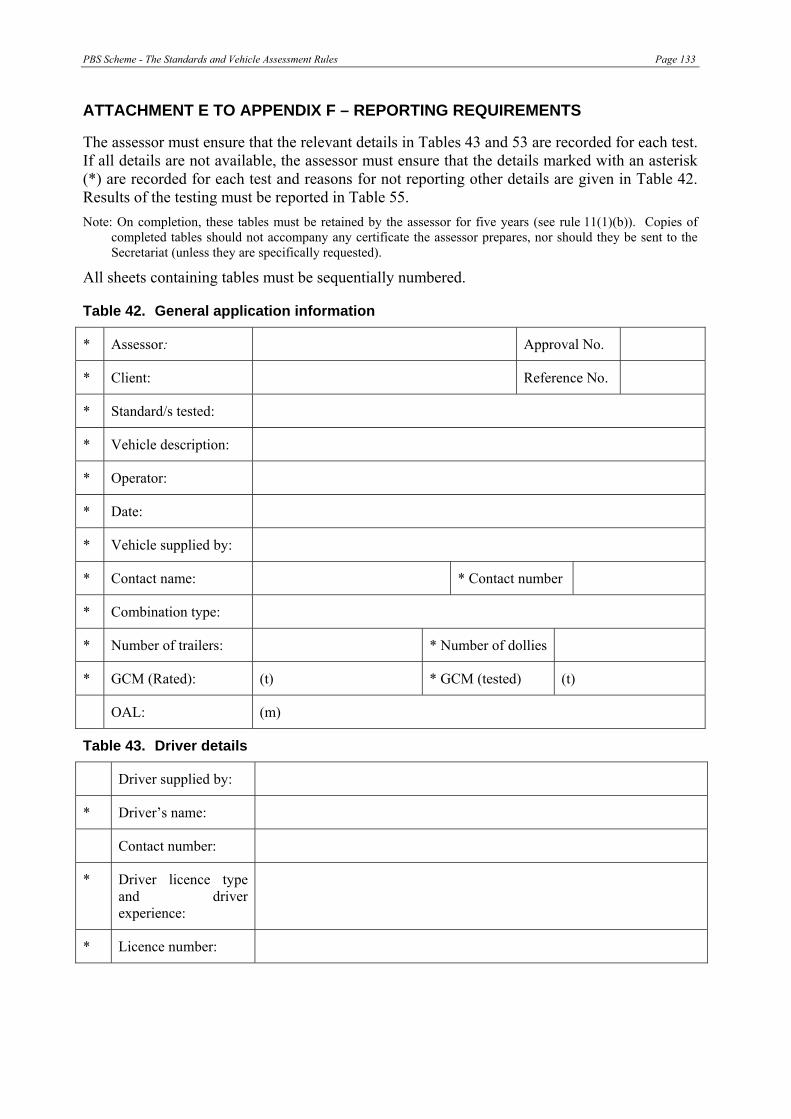
PBS Scheme - The Standards and Vehicle Assessment Rules Page 133
ATTACHMENT E TO APPENDIX F – REPORTING REQUIREMENTS
The assessor must ensure that the relevant details in Tables 43 and 53 are recorded for each test. If all details are not available, the assessor must ensure that the details marked with an asterisk (*) are recorded for each test and reasons for not reporting other details are given in Table 42. Results of the testing must be reported in Table 55. Note: On completion, these tables must be retained by the assessor for five years (see rule 11(1)(b)). Copies of
completed tables should not accompany any certificate the assessor prepares, nor should they be sent to the Secretariat (unless they are specifically requested).
All sheets containing tables must be sequentially numbered.
Table 42. General application information
* Assessor: Approval No.
* Client: Reference No.
* Standard/s tested:
* Vehicle description:
* Operator:
* Date:
* Vehicle supplied by:
* Contact name: * Contact number
* Combination type:
* Number of trailers: * Number of dollies
* GCM (Rated): (t) * GCM (tested) (t)
OAL: (m)
Table 43. Driver details
Driver supplied by:
* Driver’s name:
Contact number:
* Driver licence type and driver experience:
* Licence number:

Page 134 PBS Scheme - The Standards and Vehicle Assessment Rules
Table 44. Prime mover specification
* Body type:
Vehicle unit no.:
* VIN:
* Make, year, model:
* Registration or permit no.:
Odometer:
Tare weight: Front Rear
* GCM rating:
* Transmission type:
* Drive type (ratio):
Engine capacity (l):
* Engine power (kW):
* No of axles: No of tyres
* Suspension type: Front Rear
* Suspension make:
* Tyre size:
* Tyre make (retread):
Tyre manufactured date:
* Description of load:
Table 45. Transducer location
Transducer X (mm) Y (mm) Z (mm)
Example: Lateral acceleration unit 1 body 2,500 0 -1,100
Note: all dimensions are referenced to first axle at ground level
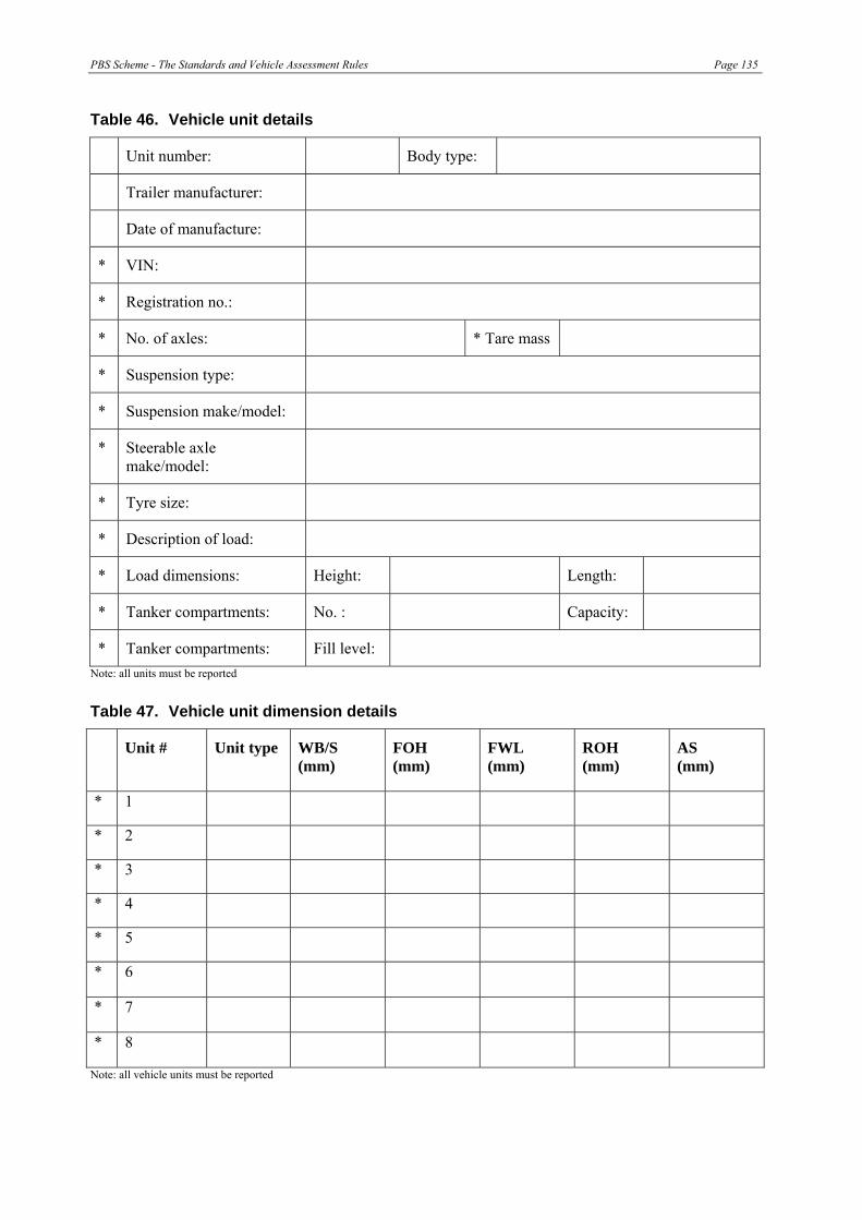
PBS Scheme - The Standards and Vehicle Assessment Rules Page 135
Table 46. Vehicle unit details
Unit number: Body type:
Trailer manufacturer:
Date of manufacture:
* VIN:
* Registration no.:
* No. of axles: * Tare mass
* Suspension type:
* Suspension make/model:
* Steerable axle make/model:
* Tyre size:
* Description of load:
* Load dimensions: Height: Length:
* Tanker compartments: No. : Capacity:
* Tanker compartments: Fill level: Note: all units must be reported
Table 47. Vehicle unit dimension details
Unit # Unit type WB/S (mm)
FOH (mm)
FWL (mm)
ROH (mm)
AS (mm)
* 1
* 2
* 3
* 4
* 5
* 6
* 7
* 8
Note: all vehicle units must be reported

Page 136 PBS Scheme - The Standards and Vehicle Assessment Rules
Table 48. Axle group mass details
Mass (t) Axle group #
Tare Laden*
1
2
3
4
5
6
7
8
9
10
11
12 Note: all axle groups must be reported
Table 49. Tyres
Unit # Make/model Tyre size Tyre pressure (psi) cold
Tread depth (mm) new
Tread depth (mm)
prior to test
Tread depth (mm)
after to test
* 1 Left
* 1 Right
* 2 Left
* 2 Right
* 3 Left
* 3 Right
* 4 Left
* 4 Right
* 5 Left
* 5 Right
* 6 Left
Note: specified tyres must be reported
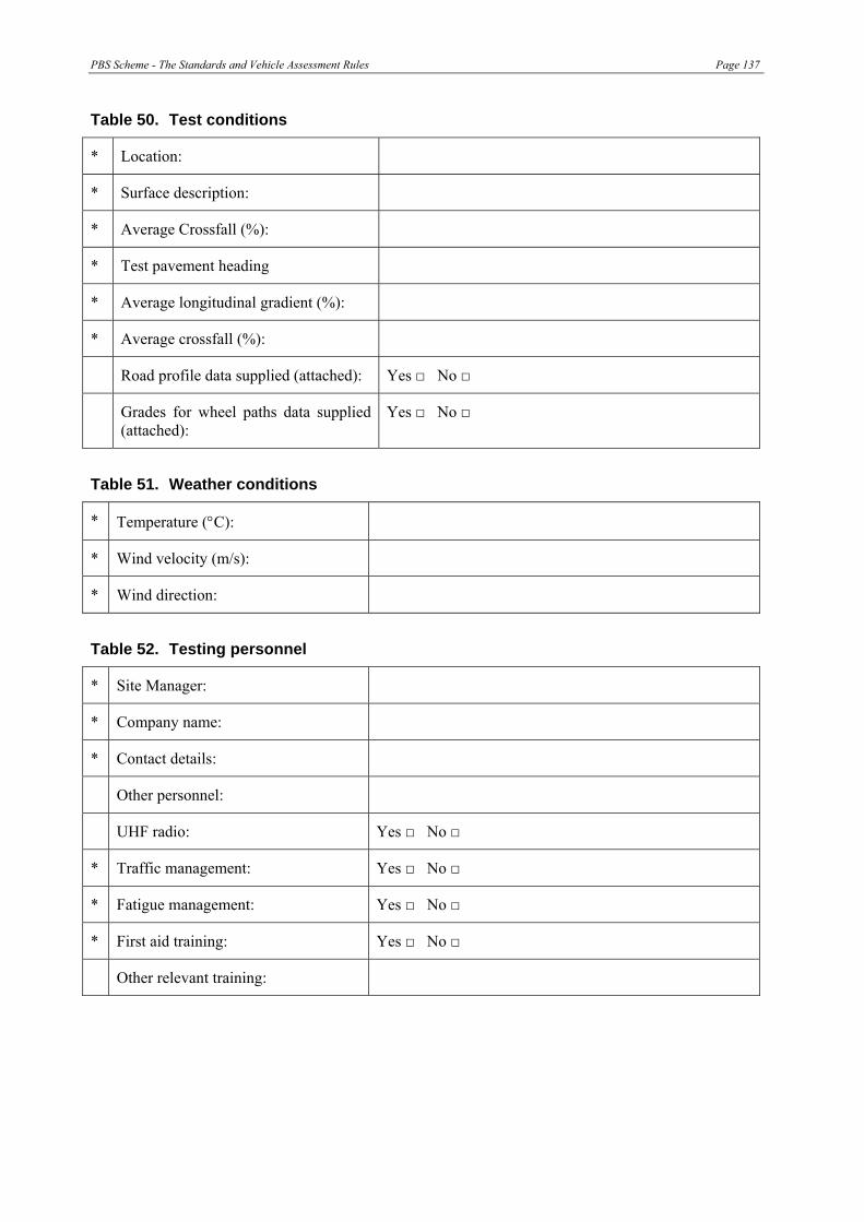
PBS Scheme - The Standards and Vehicle Assessment Rules Page 137
Table 50. Test conditions
* Location:
* Surface description:
* Average Crossfall (%):
* Test pavement heading
* Average longitudinal gradient (%):
* Average crossfall (%):
Road profile data supplied (attached): Yes □ No □
Grades for wheel paths data supplied (attached):
Yes □ No □
Table 51. Weather conditions
* Temperature (°C):
* Wind velocity (m/s):
* Wind direction:
Table 52. Testing personnel
* Site Manager:
* Company name:
* Contact details:
Other personnel:
UHF radio: Yes □ No □
* Traffic management: Yes □ No □
* Fatigue management: Yes □ No □
* First aid training: Yes □ No □
Other relevant training:

Page 138 PBS Scheme - The Standards and Vehicle Assessment Rules
Table 53. Vehicle safety check
Signed (person checking) Name (person checking)
* Prime mover GCM rating: □
* Brake connections: □
* Tyres (condition and inflation):
□
* Axle weights: □
* Driver licence: □
* Vehicle registration: □
* Oversize sign (if required): □
* Load restraints: □
* Outriggers (if required): □ Note: sign after completion of check
Table 54. Test results
Standard Results Reporting Requirement Result or Reference
Lowest Performance Level met by the Vehicle
C1: Startability F1.6 ii: the incline of the test length F1.6 iii: the road profile measurements for the
driver and passenger wheel paths
F1.6 iv: the grades for the driver and passenger wheel paths, computed from the road profile measurements, along with their associated average values
Startability result C2: Gradeability F2.6 For the standard “maintain motion”, the
value of the incline of the test length
Gradeability result For the standard “maintain speed” F2.6 i: the maximum speed at which the
vehicle satisfied the requirements of Appendix C
F2.6 ii: the road profile measurements for the driver and passenger wheel paths
F2.6 iii: the grades for the driver and passenger wheel paths, computed from the road profile measurements, along with their associated average values
C3: Acceleration Capability
F3.6 i: a distance versus time plot
F3.6 ii: a distance versus time table
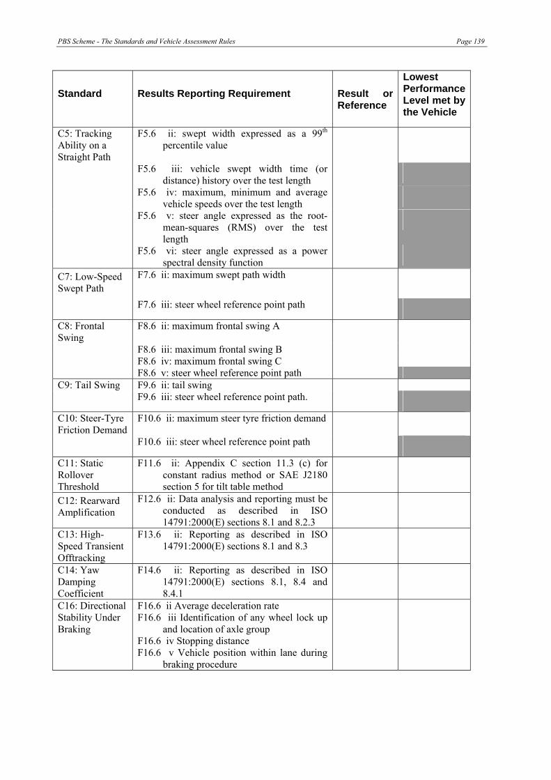
PBS Scheme - The Standards and Vehicle Assessment Rules Page 139
Standard Results Reporting Requirement Result or Reference
Lowest Performance Level met by the Vehicle
C5: Tracking Ability on a Straight Path
F5.6 ii: swept width expressed as a 99th percentile value
F5.6 iii: vehicle swept width time (or distance) history over the test length
F5.6 iv: maximum, minimum and average vehicle speeds over the test length
F5.6 v: steer angle expressed as the root-mean-squares (RMS) over the test length
F5.6 vi: steer angle expressed as a power spectral density function
C7: Low-Speed Swept Path
F7.6 ii: maximum swept path width
F7.6 iii: steer wheel reference point path
C8: Frontal Swing
F8.6 ii: maximum frontal swing A
F8.6 iii: maximum frontal swing B F8.6 iv: maximum frontal swing C F8.6 v: steer wheel reference point path C9: Tail Swing F9.6 ii: tail swing F9.6 iii: steer wheel reference point path.
C10: Steer-Tyre Friction Demand
F10.6 ii: maximum steer tyre friction demand
F10.6 iii: steer wheel reference point path
C11: Static Rollover Threshold
F11.6 ii: Appendix C section 11.3 (c) for constant radius method or SAE J2180 section 5 for tilt table method
C12: Rearward Amplification
F12.6 ii: Data analysis and reporting must be conducted as described in ISO 14791:2000(E) sections 8.1 and 8.2.3
C13: High-Speed Transient Offtracking
F13.6 ii: Reporting as described in ISO 14791:2000(E) sections 8.1 and 8.3
C14: Yaw Damping Coefficient
F14.6 ii: Reporting as described in ISO 14791:2000(E) sections 8.1, 8.4 and 8.4.1
C16: Directional Stability Under Braking
F16.6 ii Average deceleration rate F16.6 iii Identification of any wheel lock up
and location of axle group F16.6 iv Stopping distance F16.6 v Vehicle position within lane during
braking procedure

Page 140 PBS Scheme - The Standards and Vehicle Assessment Rules
Table 55. Comments
Reasons why some details are not supplied:
Other comments:
Assessor signature
_______________________________Date:__________________

PBS Scheme - The Standards and Vehicle Assessment Rules Page 141
APPENDIX G – VEHICLE CERTIFICATION INFORMATION
Instructions for the assessor
1. The assessor must complete Column 3 in accordance with the requirements of rules 9 and 10 of The Standards and Vehicle Assessment Rules for each vehicle design being assessed. If the proposed vehicle is a combination, Part A2 and Part A3 must be completed for each trailer/semi trailer and dolly in the combination.
2. Some rows of column 3 may be left blank provided the category or component is adequately described elsewhere in the Schedule.
3. When the vehicle design is completely described, the assessor must sign the certificate below.
Assessor name and approval number Date: Description of vehicle design being assessed I certify that Column 3 provides a complete specification of the potential vehicle described above in accordance with The Standards and Vehicle Assessment Rules
Signed:
Office use only:
Date received: Draft Approval No:
Date dispatched to Certifier 1
Name of Certifier 1 Approved (yes/no)
Date dispatched to Certifier 2
Name of Certifier 2 Approved (yes/no)
Date dispatched to Certifier 3
Name of Certifier 3 Approved (yes/no)

Page 142 PBS Scheme - The Standards and Vehicle Assessment Rules
Instructions for the certifier
4. The certifier must complete Columns 4 and 5 after having inspected the vehicle in accordance with the requirements of the Vehicle Certification Rules.
5. If the physical requirement in Column 3 (Specification) is present on the vehicle, the certifier must complete Column 4 with a yes and provide a justification for the yes. For example, it may be simply that the dimensions are correct and the justification is “measured”, it may be that the specified engine is present and the engine manufacturer has provided a documentation as to torque speed characteristics. Column 5 would be completed by indicating that inspection showed that the specified engine was present and the documentation from the engine manufacturer was satisfactory and is attached to this form (in accordance with the Vehicle Certification Rules).
6. If the physical requirement in Column 3 (Specification) is not present on the vehicle, the Inspector must complete Column 4 with a no and provide any justification for the no.
7. If a yes answer is present in Column 4 for each specification in Column 3, the certifier must complete the certifier’s certificate required by the Vehicle Certification Rules and must fulfil the other requirements of those Rules.
8. If a no answer is present in Column 4 for any specification in Column 3, the certifier must not complete the certificate.
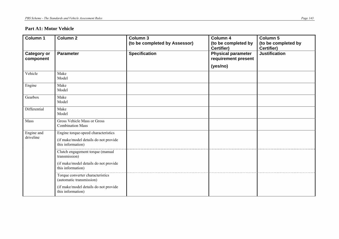
PBS Scheme - The Standards and Vehicle Assessment Rules Page 143
Part A1: Motor Vehicle
Column 1 Column 2 Column 3 (to be completed by Assessor)
Column 4 (to be completed by Certifier)
Column 5 (to be completed by Certifier)
Category or component
Parameter Specification Physical parameter requirement present (yes/no)
Justification
Vehicle Make Model
Engine Make Model
Gearbox Make Model
Differential Make Model
Mass Gross Vehicle Mass or Gross Combination Mass
Engine and driveline
Engine torque-speed characteristics
(if make/model details do not provide this information)
Clutch engagement torque (manual transmission)
(if make/model details do not provide this information)
Torque converter characteristics (automatic transmission)
(if make/model details do not provide this information)

Page 144 PBS Scheme - The Standards and Vehicle Assessment Rules
Column 1 Column 2 Column 3 (to be completed by Assessor)
Column 4 (to be completed by Certifier)
Column 5 (to be completed by Certifier)
Category or component
Parameter Specification Physical parameter requirement present (yes/no)
Justification
Gearbox and final drive ratios
(if make/model details do not provide this information)
Automatic transmission shift time delays
(if make/model details do not provide this information)
Tyre size, make and model OR Tyres (specify for each axle group) Tyre rolling radius, cornering
characteristics and vertical stiffness
Body type Body/ construction Wheelbase
King pin lead or coupling rear overhang
Front overhang, width plan-profile and plan-profile of front outside corners and protuberances
Rear overhang
Plan-profile of rear outside corners and protuberances
Suspension (specify for each axle group)
Suspension make and model OR suspension characteristics

PBS Scheme - The Standards and Vehicle Assessment Rules Page 145
Column 1 Column 2 Column 3 (to be completed by Assessor)
Column 4 (to be completed by Certifier)
Column 5 (to be completed by Certifier)
Category or component
Parameter Specification Physical parameter requirement present (yes/no)
Justification
Drive group axle spread (if applicable)
Track width, and dual tyre spacing (if applicable)
Wheels and axles (specify for each axle group)
Axle spacing and axle steering
Drive axle group tractive effort distribution
Couplings Couplings (conventional, double oscillating turntables, ball, other)
Other Any additional or special requirements
Part A2: Trailer/Semi-trailer
Column 1 Column 2 Column 3 (to be completed by Assessor)
Column 4 (to be completed by Certifier)
Column 5 (to be completed by Certifier)
Category or component
Parameter Specification Physical parameter requirement present
(yes/no)
Justification
Trailer Make Model
Mass Aggregate Trailer Mass
Tyres Tyre size, make and model OR
Tyre rolling radius, cornering characteristics and vertical stiffness

Page 146 PBS Scheme - The Standards and Vehicle Assessment Rules
Column 1 Column 2 Column 3 (to be completed by Assessor)
Column 4 (to be completed by Certifier)
Column 5 (to be completed by Certifier)
Category or component
Parameter Specification Physical parameter requirement present
(yes/no)
Justification
Body/ construction
Body type
Wheelbase
King pin/pivot pin lead or coupling rear overhang
Drawbar length
Width plan-profile
Forward projection and plan-profile of front outside corners and protuberances
Rear overhang
Plan-profile of rear outside corners and protuberances
Suspension Suspension make and model OR suspension characteristics
Wheels and axles
Track width, and dual tyre spacing (if applicable)
Axle spacing & axle steering
Couplings Couplings (conventional, double oscillating turntables, ball, other)
Other Any additional or special requirements
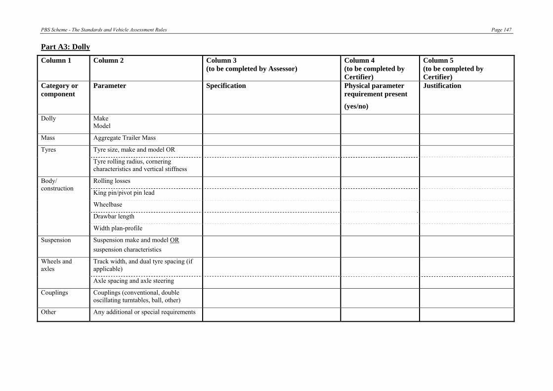
PBS Scheme - The Standards and Vehicle Assessment Rules Page 147
Part A3: Dolly
Column 1 Column 2 Column 3 (to be completed by Assessor)
Column 4 (to be completed by Certifier)
Column 5 (to be completed by Certifier)
Category or component
Parameter Specification Physical parameter requirement present
(yes/no)
Justification
Dolly Make Model
Mass Aggregate Trailer Mass
Tyres Tyre size, make and model OR
Tyre rolling radius, cornering characteristics and vertical stiffness
Rolling losses
King pin/pivot pin lead
Body/ construction
Wheelbase
Drawbar length
Width plan-profile
Suspension Suspension make and model OR suspension characteristics
Wheels and axles
Track width, and dual tyre spacing (if applicable)
Axle spacing and axle steering
Couplings Couplings (conventional, double oscillating turntables, ball, other)
Other Any additional or special requirements


The Standards and Vehicle Assessment Rules Page 149
APPENDIX H – RISK SENSITIVE PARAMETERS RELATED TO VEHICLE DESIGN FEATURES
Table H1(a) Longitudinal Performance (Low Speed) – Startability Standard Critical Parameter Potential Issues Initial Rank Assessors
Rank Off-baseline variation used (%)
Startability Gross Vehicle Mass or Gross Combination Mass Drive axle group load should be not less than assumed in the assessment.
1
Engine torque-speed characteristics If vehicle is to operate at altitude de-rating of engine with altitude could be an issue and needs to be checked.
1
Clutch engagement torque (manual transmission) or torque converter characteristics (automatic transmission)
Not readily available, in which case a conservative value should be used in the analysis.
1
Gearbox and final drive ratios 1 Tyre rolling radius (drive axle group) Radius should be for new tyre at the
recommended inflation pressure, which has the largest loaded radius.
1
Drive train mechanical losses of the hauling unit (rigid truck, bus, prime mover)
Values supplied may be approximate, in which case a conservative value should be used in the analysis.
2
Rolling losses (semi-trailer, dolly, trailers) Values supplied may be approximate, in which case a conservative value should be used in the analysis.
2
Table H1 (b) Longitudinal Performance (Low Speed) – Gradeability Standard Critical Parameter Potential Issues Initial Rank Assessors
Rank Off-baseline variation used (%)
Gradeability Gross Vehicle Mass or Gross Combination Mass To prevent loss of traction drive axle group load should be not less than assumed in the assessment.
1
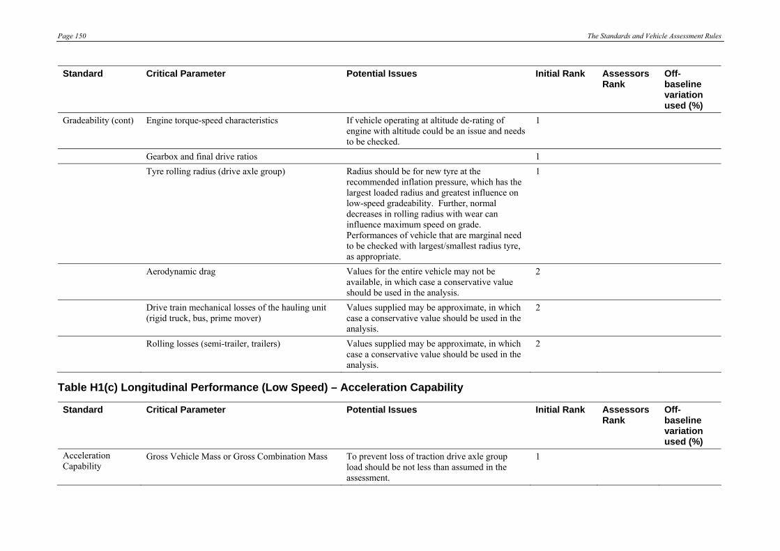
Page 150 The Standards and Vehicle Assessment Rules
Standard Critical Parameter Potential Issues Initial Rank Assessors Rank
Off-baseline variation used (%)
Gradeability (cont) Engine torque-speed characteristics If vehicle operating at altitude de-rating of engine with altitude could be an issue and needs to be checked.
1
Gearbox and final drive ratios 1 Tyre rolling radius (drive axle group) Radius should be for new tyre at the
recommended inflation pressure, which has the largest loaded radius and greatest influence on low-speed gradeability. Further, normal decreases in rolling radius with wear can influence maximum speed on grade. Performances of vehicle that are marginal need to be checked with largest/smallest radius tyre, as appropriate.
1
Aerodynamic drag Values for the entire vehicle may not be available, in which case a conservative value should be used in the analysis.
2
Drive train mechanical losses of the hauling unit (rigid truck, bus, prime mover)
Values supplied may be approximate, in which case a conservative value should be used in the analysis.
2
Rolling losses (semi-trailer, trailers) Values supplied may be approximate, in which case a conservative value should be used in the analysis.
2
Table H1(c) Longitudinal Performance (Low Speed) – Acceleration Capability
Standard Critical Parameter Potential Issues Initial Rank Assessors Rank
Off-baseline variation used (%)
Acceleration Capability
Gross Vehicle Mass or Gross Combination Mass To prevent loss of traction drive axle group load should be not less than assumed in the assessment.
1

The Standards and Vehicle Assessment Rules Page 151
Standard Critical Parameter Potential Issues Initial Rank Assessors Rank
Off-baseline variation used (%)
Acceleration Capability (cont)
Engine torque-speed characteristics If vehicle operating at altitude de-rating of engine with altitude could be an issue and needs to be checked.
1
Gearbox and final drive ratios 1 Tyre rolling radius (drive axle group) Radius should be for new tyre at the
recommended inflation pressure, which has the largest loaded radius.
1
Time delays associated with gear shifting (automatic transmissions only). For manual transmissions this parameter is driver dependent.
Gearshift times for manual transmissions used in the analysis must not be too short and must reflect real world situation.
1
Drive train mechanical losses of the hauling unit (rigid truck, bus, prime mover)
Values supplied may be approximate, in which case a conservative value should be used in the analysis.
2
Rolling losses (semi-trailer, trailers) Values supplied may be approximate, in which case a conservative value should be used in the analysis.
2
Table H2 (a) Longitudinal Performance (High Speed) – Tracking Ability on a Straight Path Standard Critical Parameter Potential Issues Initial Rank Assessors
Rank Off-baseline variation used (%)
Tracking Ability on a Straight Path
Tyre cornering characteristics If generic, non-descript tyres were used in the analysis these should have cornering characteristics that are consistent with worst-case performing tyres of the same size to ensure that any tyre of the same size can be used.
1
Centre-of-gravity height of each vehicle unit, and load offset (if applicable)
May not be possible or convenient to conduct tilt test. For some loads payload centre-of-gravity heights may be difficult to estimate.
1
Gross Vehicle Mass or Gross Combination Mass 1
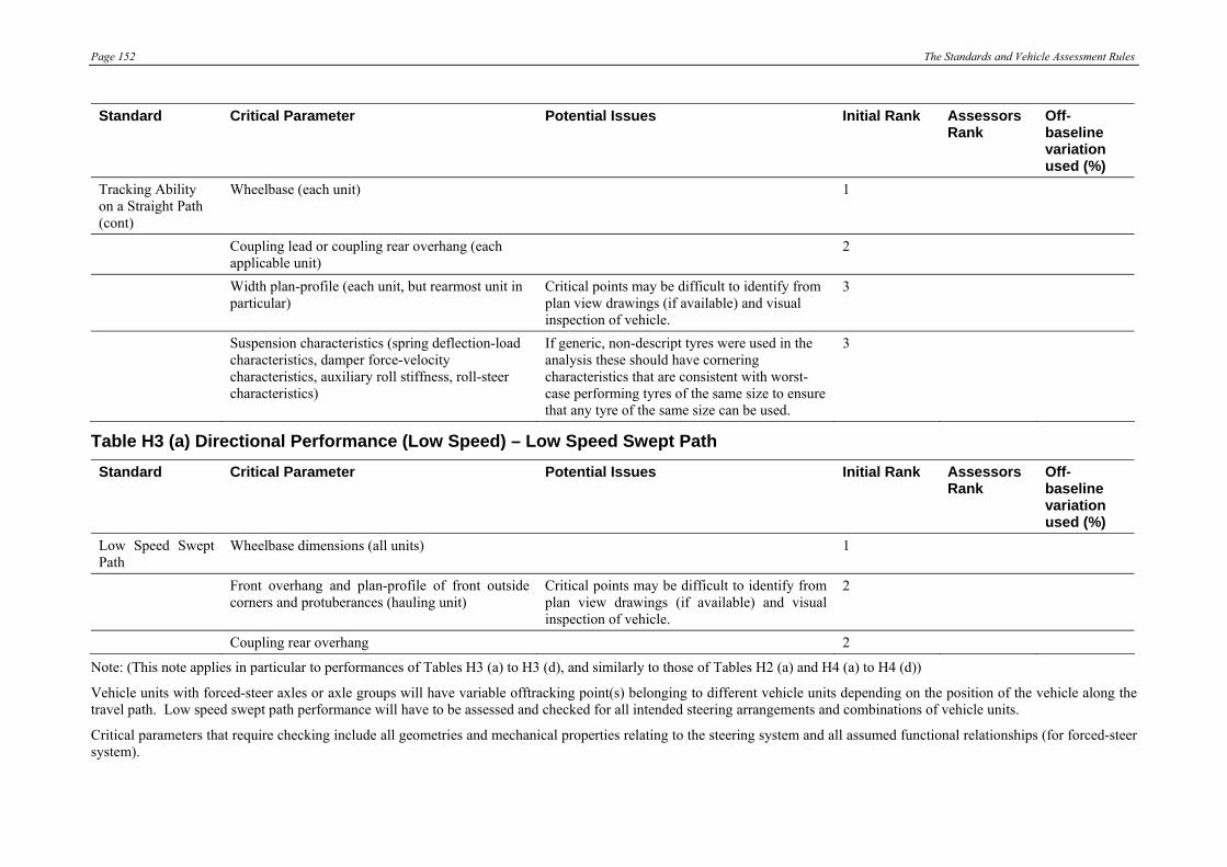
Page 152 The Standards and Vehicle Assessment Rules
Standard Critical Parameter Potential Issues Initial Rank Assessors Rank
Off-baseline variation used (%)
Tracking Ability on a Straight Path (cont)
Wheelbase (each unit) 1
Coupling lead or coupling rear overhang (each applicable unit)
2
Width plan-profile (each unit, but rearmost unit in particular)
Critical points may be difficult to identify from plan view drawings (if available) and visual inspection of vehicle.
3
Suspension characteristics (spring deflection-load characteristics, damper force-velocity characteristics, auxiliary roll stiffness, roll-steer characteristics)
If generic, non-descript tyres were used in the analysis these should have cornering characteristics that are consistent with worst-case performing tyres of the same size to ensure that any tyre of the same size can be used.
3
Table H3 (a) Directional Performance (Low Speed) – Low Speed Swept Path Standard Critical Parameter Potential Issues Initial Rank Assessors
Rank Off-baseline variation used (%)
Low Speed Swept Path
Wheelbase dimensions (all units) 1
Front overhang and plan-profile of front outside corners and protuberances (hauling unit)
Critical points may be difficult to identify from plan view drawings (if available) and visual inspection of vehicle.
2
Coupling rear overhang 2
Note: (This note applies in particular to performances of Tables H3 (a) to H3 (d), and similarly to those of Tables H2 (a) and H4 (a) to H4 (d))
Vehicle units with forced-steer axles or axle groups will have variable offtracking point(s) belonging to different vehicle units depending on the position of the vehicle along the travel path. Low speed swept path performance will have to be assessed and checked for all intended steering arrangements and combinations of vehicle units.
Critical parameters that require checking include all geometries and mechanical properties relating to the steering system and all assumed functional relationships (for forced-steer system).

The Standards and Vehicle Assessment Rules Page 153
Table H3 (b) Directional Performance (Low Speed) – Frontal Swing Standard Critical Parameter Potential Issues Initial Rank Assessors
Rank Off-baseline variation used (%)
Frontal Swing Front overhang (hauling unit) and forward projection (lead semi-trailer)
1
Plan-profile of front outside corners and protuberances (hauling unit and lead semi-trailer)
Critical points may be difficult to identify from plan view drawings (if available) and visual inspection of vehicle.
1
Rigid truck/bus, prime mover wheelbase 1 Wheelbase of first semi-trailer 2
Table H3(c) Directional Performance (Low Speed) – Tail Swing Standard Critical Parameter Potential Issues Initial Rank Assessors
Rank Off-baseline variation used (%)
Tail Swing Rear overhang of rigid truck/bus, or rear overhang of first semi-trailer if articulated vehicle
1
Plan-profile of rear outside corners and protuberances (vehicle unit that has the critical overhang dimension)
Critical points may be difficult to identify from plan view drawings (if available) and visual inspection of vehicle.
1
Wheelbase of vehicle unit that has the critical overhang dimension
2
Table H3 (d) Directional Performance (Low Speed) – Steer Tyre Friction Demand Standard Critical Parameter Potential Issues Initial Rank Assessors
Rank Off-baseline variation used (%)
Steer Tyre Friction Demand
Wheelbase of rigid truck/bus or prime mover 1
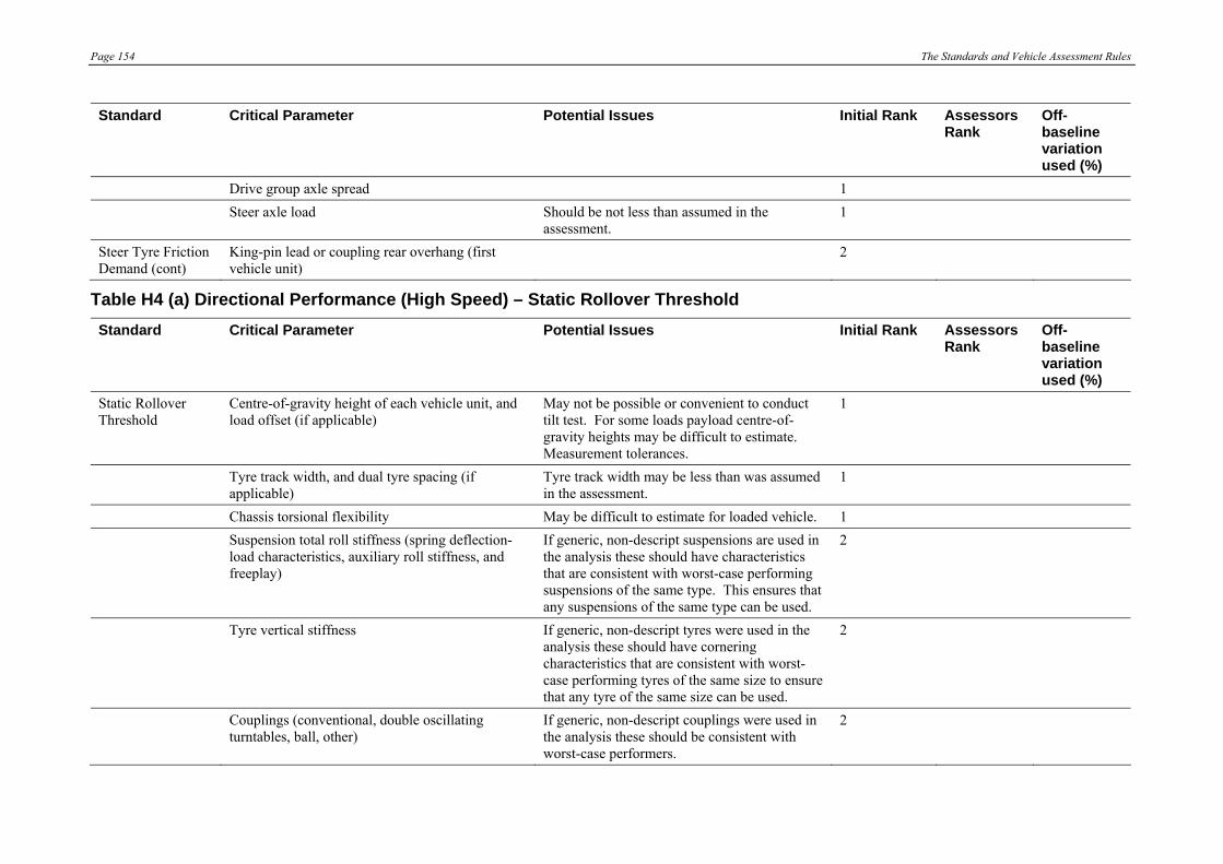
Page 154 The Standards and Vehicle Assessment Rules
Standard Critical Parameter Potential Issues Initial Rank Assessors Rank
Off-baseline variation used (%)
Drive group axle spread 1 Steer axle load Should be not less than assumed in the
assessment. 1
Steer Tyre Friction Demand (cont)
King-pin lead or coupling rear overhang (first vehicle unit)
2
Table H4 (a) Directional Performance (High Speed) – Static Rollover Threshold Standard Critical Parameter Potential Issues Initial Rank Assessors
Rank Off-baseline variation used (%)
Static Rollover Threshold
Centre-of-gravity height of each vehicle unit, and load offset (if applicable)
May not be possible or convenient to conduct tilt test. For some loads payload centre-of-gravity heights may be difficult to estimate. Measurement tolerances.
1
Tyre track width, and dual tyre spacing (if applicable)
Tyre track width may be less than was assumed in the assessment.
1
Chassis torsional flexibility May be difficult to estimate for loaded vehicle. 1 Suspension total roll stiffness (spring deflection-
load characteristics, auxiliary roll stiffness, and freeplay)
If generic, non-descript suspensions are used in the analysis these should have characteristics that are consistent with worst-case performing suspensions of the same type. This ensures that any suspensions of the same type can be used.
2
Tyre vertical stiffness If generic, non-descript tyres were used in the analysis these should have cornering characteristics that are consistent with worst-case performing tyres of the same size to ensure that any tyre of the same size can be used.
2
Couplings (conventional, double oscillating turntables, ball, other)
If generic, non-descript couplings were used in the analysis these should be consistent with worst-case performers.
2

The Standards and Vehicle Assessment Rules Page 155
Standard Critical Parameter Potential Issues Initial Rank Assessors Rank
Off-baseline variation used (%)
Tyre cornering characteristics If generic, non-descript tyres were used in the analysis these should have cornering characteristics that are consistent with worst-case performing tyres of the same size to ensure that any tyre of the same size can be used.
3
Table H4 (b) Directional Performance (High Speed) – Rearward Amplification Standard Critical Parameter Potential Issues Initial Rank Assessors
Rank Off-baseline variation used (%)
Rearward Amplification
Tyre cornering characteristics If generic, non-descript tyres were used in the analysis these should have cornering characteristics that are consistent with worst-case performing tyres of the same size to ensure that any tyre of the same size can be used.
1
Wheelbase (trailer and semi-trailer) 1 Centre-of-gravity height of each vehicle unit, and
load offset (if applicable) May not be possible or convenient to conduct tilt test. For some loads payload centre-of-gravity heights may be difficult to estimate. Measurement tolerances.
1
Chassis torsional flexibility May be difficult to estimate for loaded vehicle. 1 Coupling lead or coupling rear overhang (each
applicable unit) 2
Wheelbase (dolly) 3 Wheelbase (prime mover) 3
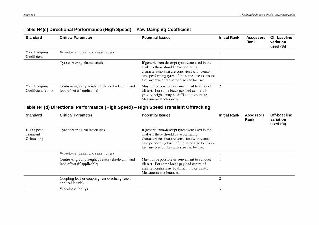
Page 156 The Standards and Vehicle Assessment Rules
Table H4(c) Directional Performance (High Speed) – Yaw Damping Coefficient Standard Critical Parameter Potential Issues Initial Rank Assessors
Rank Off-baseline variation used (%)
Yaw Damping Coefficient
Wheelbase (trailer and semi-trailer) 1
Tyre cornering characteristics If generic, non-descript tyres were used in the analysis these should have cornering characteristics that are consistent with worst-case performing tyres of the same size to ensure that any tyre of the same size can be used.
1
Yaw Damping Coefficient (cont)
Centre-of-gravity height of each vehicle unit, and load offset (if applicable)
May not be possible or convenient to conduct tilt test. For some loads payload centre-of-gravity heights may be difficult to estimate. Measurement tolerances.
2
Table H4 (d) Directional Performance (High Speed) – High Speed Transient Offtracking Standard Critical Parameter Potential Issues Initial Rank Assessors
Rank Off-baseline variation used (%)
High Speed Transient Offtracking
Tyre cornering characteristics If generic, non-descript tyres were used in the analysis these should have cornering characteristics that are consistent with worst-case performing tyres of the same size to ensure that any tyre of the same size can be used.
1
Wheelbase (trailer and semi-trailer) 1 Centre-of-gravity height of each vehicle unit, and
load offset (if applicable) May not be possible or convenient to conduct tilt test. For some loads payload centre-of-gravity heights may be difficult to estimate. Measurement tolerances.
1
Coupling lead or coupling rear overhang (each applicable unit)
2
Wheelbase (dolly) 3

The Standards and Vehicle Assessment Rules Page 157
APPENDIX I – RISK SENSITIVE PARAMETERS RELATED TO VEHICLE OPERATING FACTORS
Table I1(a): Longitudinal Performance (Low Speed) – Startability Standard Critical Parameter Potential Issues Initial Rank Assessors
Rank Off-baseline
variation used (%)
Startability, Gradeability and Acceleration Capability
Gross Vehicle Mass or Gross Combination Mass To prevent loss of traction, drive axle group load should be not less than critical value assumed in the assessment.
1
Tyre rolling radius (drive axle group) 2
Table I1 (b) Longitudinal Performance (Low Speed) – Gradeability Standard Critical Parameter Potential Issues Initial Rank Assessors
Rank Off-baseline
variation used (%)
Gradeability Gross Vehicle Mass or Gross Combination Mass 1 Tyre rolling radius (drive axle group) 2
Table I1(c) Longitudinal Performance (Low Speed) – Acceleration Capability Standard Critical Parameter Potential Issues Initial Rank Assessors
Rank Off-baseline
variation used (%)
Acceleration Capability
Gross Vehicle Mass or Gross Combination Mass To prevent loss of traction, drive axle group load should be not less than critical value assumed in the assessment.
1
Tyre rolling radius (drive axle group) 2

Page 158 The Standards and Vehicle Assessment Rules
Table I2 (a) Longitudinal Performance (High Speed) – Tracking Ability on a Straight Path Standard Critical Parameter Potential Issues Initial Rank Assessors
Rank Off-baseline variation used (%)
Tracking Ability on a Straight Path
Tyre cornering characteristics Tyre cornering characteristics are sensitive to inflation pressure, tread pattern and wear.
1
Centre-of-gravity height of each vehicle unit, and load offset (if applicable)
For some loads payload centre-of-gravity heights may be difficult to estimate. Slosh effects of liquid loads.
1
Gross Vehicle Mass or Gross Combination Mass 1 Suspensions Characteristics sensitive to airbag pressure
(potential issue only applicable to airbag suspensions).
3
Table I3 (a) Directional Performance (Low Speed) – Low Speed Swept Path Standard Critical Parameter Potential Issues Initial Rank Assessors
Rank Off-baseline variation used (%)
Low Speed Swept Path
Note: Vehicle units with forced-steer axles or axle groups will require special consideration and treatment to be defined by the Assessor and/or manufacturer. This note applies in particular to performances of Tables B3(a) to B3(d), and similarly to those of Tables B2(a) and B4(a) to B4(d).
Table I3(b) Directional Performance (Low Speed) – Frontal Swing Standard Critical Parameter Potential Issues Initial Rank Assessors
Rank Off-baseline variation used (%)
Frontal Swing
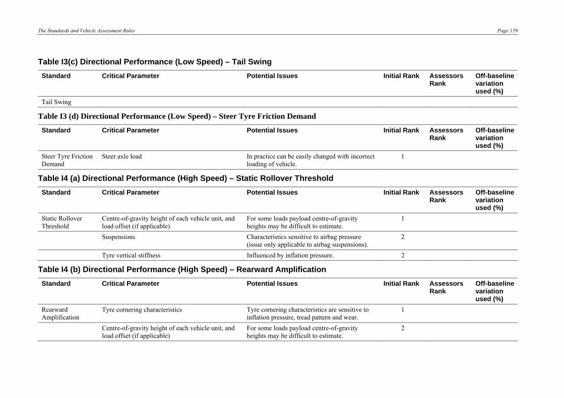
The Standards and Vehicle Assessment Rules Page 159
Table I3(c) Directional Performance (Low Speed) – Tail Swing Standard Critical Parameter Potential Issues Initial Rank Assessors
Rank Off-baseline variation used (%)
Tail Swing
Table I3 (d) Directional Performance (Low Speed) – Steer Tyre Friction Demand
Standard Critical Parameter Potential Issues Initial Rank Assessors Rank
Off-baseline variation used (%)
Steer Tyre Friction Demand
Steer axle load In practice can be easily changed with incorrect loading of vehicle.
1
Table I4 (a) Directional Performance (High Speed) – Static Rollover Threshold Standard Critical Parameter Potential Issues Initial Rank Assessors
Rank Off-baseline variation used (%)
Static Rollover Threshold
Centre-of-gravity height of each vehicle unit, and load offset (if applicable)
For some loads payload centre-of-gravity heights may be difficult to estimate.
1
Suspensions Characteristics sensitive to airbag pressure (issue only applicable to airbag suspensions).
2
Tyre vertical stiffness Influenced by inflation pressure. 2
Table I4 (b) Directional Performance (High Speed) – Rearward Amplification Standard Critical Parameter Potential Issues Initial Rank Assessors
Rank Off-baseline variation used (%)
Rearward Amplification
Tyre cornering characteristics Tyre cornering characteristics are sensitive to inflation pressure, tread pattern and wear.
1
Centre-of-gravity height of each vehicle unit, and load offset (if applicable)
For some loads payload centre-of-gravity heights may be difficult to estimate.
2

Page 160 The Standards and Vehicle Assessment Rules
Table I4(c) Directional Performance (High Speed) – Yaw Damping Coefficient Standard Critical Parameter Potential Issues Initial Rank Assessors
Rank Off-baseline variation used (%)
Yaw Damping Coefficient
Tyre cornering characteristics Tyre cornering characteristics are sensitive to inflation pressure, tread pattern and wear.
1
Centre-of-gravity height of each vehicle unit, and load offset (if applicable)
For some loads payload centre-of-gravity heights may be difficult to estimate.
1
Table I4 (d) Directional Performance (High Speed) – High Speed Transient Offtracking Standard Critical Parameter Potential Issues Initial Rank Assessors
Rank Off-baseline variation used (%)
High Speed Transient Offtracking
Tyre cornering characteristics Tyre cornering characteristics are sensitive to inflation pressure, tread pattern and wear.
1
Centre-of-gravity height of each vehicle unit, and load offset (if applicable)
For some loads payload centre-of-gravity heights may be difficult to estimate.
2

The Standards and Vehicle Assessment Rules Page 161
APPENDIX J – INFORMATION AND RECOMMENDATIONS CONCERNING VEHICLE OPERATING CONDITIONS
1. Acceptable Load Types
Describe completely each of the load types that were assessed. The description of a liquid load must be accompanied by a specific gravity, the description of a solid load by its assumed density and any loading patterns.
2. Mass Management
(a) If relevant, specify the centre-of-gravity height of each load type on each motor vehicle and trailer or semi-trailer (as appropriate) that was assumed in the assessment.
Motor vehicle Semi-trailer(s) Trailer(s)
Centre-of-gravity height and load offset (if applicable)
(b) Specify any part loading conditions to be avoided that are derived from the ‘least favourable loading condition’ in The Standards and Rules for Assessment for Vehicles.
Specification
3. Tyres
(a) Specify maximum and minimum tyre pressures for each axle group (or each axle if different within a group)
Motor vehicle
Steer axle(s) Drive axle(s) Semi-trailer(s) Trailer(s)
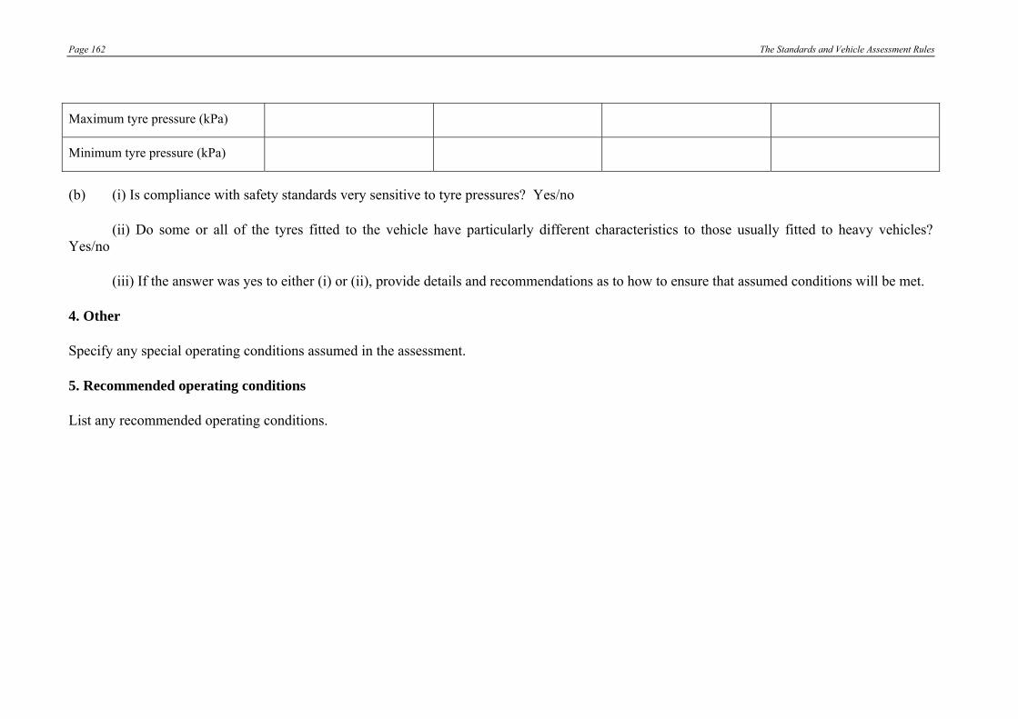
Page 162 The Standards and Vehicle Assessment Rules
Maximum tyre pressure (kPa)
Minimum tyre pressure (kPa)
(b) (i) Is compliance with safety standards very sensitive to tyre pressures? Yes/no
(ii) Do some or all of the tyres fitted to the vehicle have particularly different characteristics to those usually fitted to heavy vehicles? Yes/no
(iii) If the answer was yes to either (i) or (ii), provide details and recommendations as to how to ensure that assumed conditions will be met.
4. Other
Specify any special operating conditions assumed in the assessment.
5. Recommended operating conditions
List any recommended operating conditions.
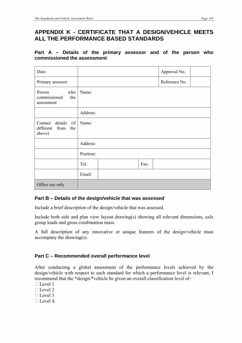
The Standards and Vehicle Assessment Rules Page 163
APPENDIX K - CERTIFICATE THAT A DESIGN/VEHICLE MEETS ALL THE PERFORMANCE BASED STANDARDS Part A – Details of the primary assessor and of the person who commissioned the assessment Date: Approval No.
Primary assessor: Reference No.
Person who commissioned the assessment
Name:
Address:
Contact details (if different from the above)
Name:
Address:
Position:
Tel: Fax:
Email:
Office use only
Part B – Details of the design/vehicle that was assessed
Include a brief description of the design/vehicle that was assessed.
Include both side and plan view layout drawing(s) showing all relevant dimensions, axle group loads and gross combination mass.
A full description of any innovative or unique features of the design/vehicle must accompany the drawing(s).
Part C – Recommended overall performance level After conducting a global assessment of the performance levels achieved by the design/vehicle with respect to each standard for which a performance level is relevant, I recommend that the *design/*vehicle be given an overall classification level of– Level 1 Level 2 Level 3 Level 4.

Page 164 The Standards and Vehicle Assessment Rules
Part D – Details of prescriptive requirements from which exemption needed In my opinion, the vehicle, or a vehicle built to the design, will require exemption from the following prescriptive requirements – [tick one or more of the following] clause 64 (Axle configuration) clause 65 (Relation between axles in a group) clause 66 (Width) clause 67 (Length of single motor vehicles) clause 68 (Length of single trailers) clause 69 (Length of combinations) clause 70 (Rear overhang) clause 71 (Trailer drawbar length) clause 72 (Height) clauses 169 (b) and (c) (Attachment of couplings and drawbar eyes on long road trains); clause 171 (Tow coupling overhang on long road trains) the following ADRs:
Rule 43, clause 6.1 (Length) Rule 43, clause 6.2 (Rear overhang)(other than clause 6.2.1) Rule 43, clause 6.2.1 (Rear overhang) Rule 43, clause 6.3 (Height) Rule 43, clause 6.5 (Width) Rule 43, clause 9.4 (Retractable axles) Rule 43, clause 9.5 (Retractable axles) Rule 62, clause 5.3 (Tow coupling overhang) Rule 63, clause 63.5.1 (Tow coupling location)
Part E – Details of the results of the assessment against infrastructure
standards Attach results of the assessments conducted in accordance with Appendix A. Part F – Details of the results of the assessment against safety standards If any part of the assessment has been undertaken by numerical simulation, attach Table 36. If any part of the assessment has been undertaken by testing, attach Table 55. If any part of the assessment relies on an assessment made by one or more other assessors, attach copy of certificate relied on from those other assessments. Part G – Details of vehicle physical characteristics Attach the Vehicle Certification Information (Appendix G) for the vehicle.
The Standards and Vehicle Assessment Rules Page 165
Part H – Details of sensitivity testing If any risk sensitivity testing was undertaken, attach copy of completed Appendix H or I or both, as the case may be. Part I – Details of critical characteristics Include a list of the vehicle physical characteristics that are most important to the capability of the vehicle, or a vehicle built to the design, to comply with, or to continue to comply with, the standards. Part J – Details of vehicle operating conditions Attach Appendix J (Information and recommendations concerning vehicle operating conditions). If recommending that an operator, as a national operating condition, be required to have a quality system to control the performance of the vehicle, the recommendation must include the items that must be specified in the quality system. Part K – Details of assumptions relied on Include a list of assumptions on which reliance has been placed in conducting the assessment, or in forming an opinion in relation to the design or vehicle. Part L – Certification I certify: (a) that in my opinion, based on the assessment I have undertaken:
*(i) a vehicle built to the design set out under Part B will meet all the infrastructure and safety standards set out in Appendices A and C of The Standards and Vehicle Assessment Rules;
*(ii) the vehicle described under Part B meets all the infrastructure and safety
standards set out in Appendices A and C of The Standards and Vehicle Assessment Rules;
(* omit whichever paragraph does not apply)
(b) that all details given in Parts A to K are true and correct or, in the case of an
opinion, accurately express my opinion.

Page 166 The Standards and Vehicle Assessment Rules
Name:
Signature:
Date:
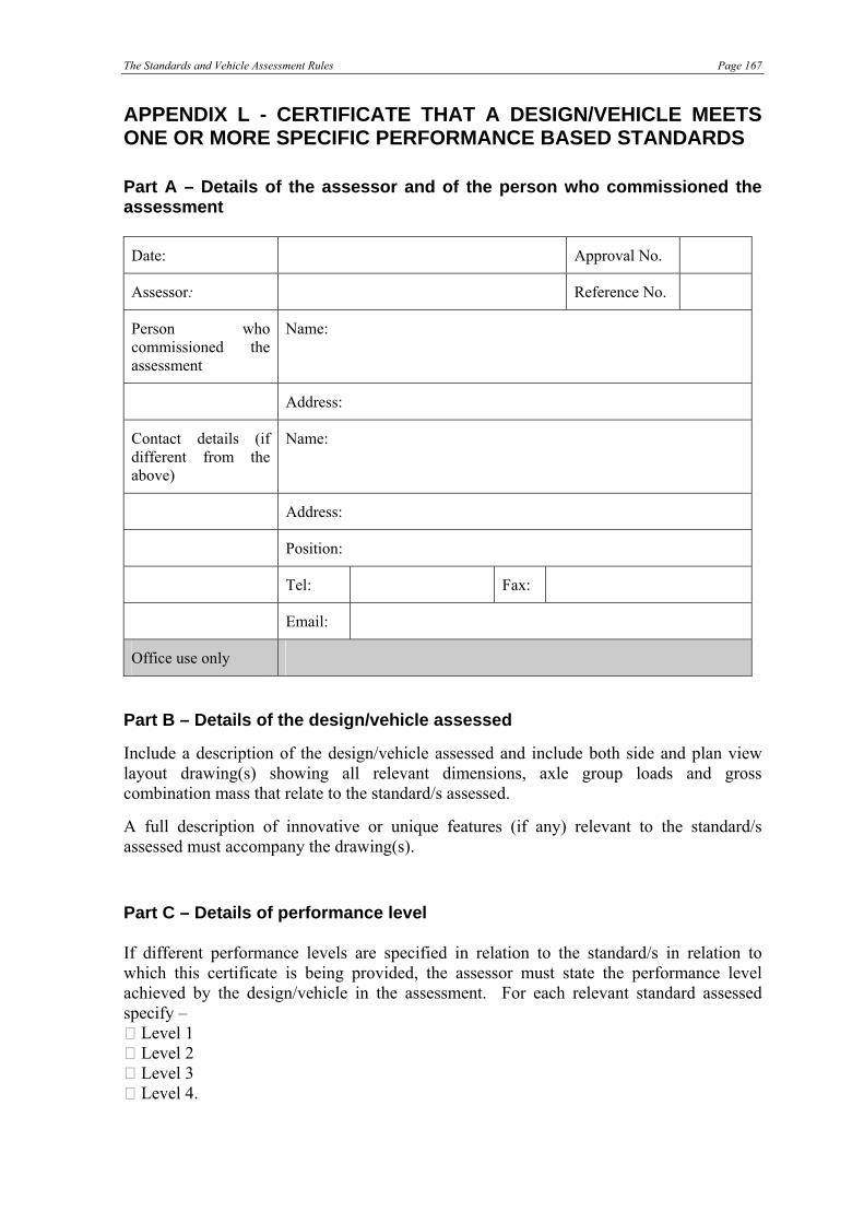
The Standards and Vehicle Assessment Rules Page 167
APPENDIX L - CERTIFICATE THAT A DESIGN/VEHICLE MEETS ONE OR MORE SPECIFIC PERFORMANCE BASED STANDARDS Part A – Details of the assessor and of the person who commissioned the assessment Date: Approval No.
Assessor: Reference No.
Person who commissioned the assessment
Name:
Address:
Contact details (if different from the above)
Name:
Address:
Position:
Tel: Fax:
Email:
Office use only
Part B – Details of the design/vehicle assessed
Include a description of the design/vehicle assessed and include both side and plan view layout drawing(s) showing all relevant dimensions, axle group loads and gross combination mass that relate to the standard/s assessed.
A full description of innovative or unique features (if any) relevant to the standard/s assessed must accompany the drawing(s).
Part C – Details of performance level If different performance levels are specified in relation to the standard/s in relation to which this certificate is being provided, the assessor must state the performance level achieved by the design/vehicle in the assessment. For each relevant standard assessed specify – Level 1 Level 2 Level 3 Level 4.

Page 168 The Standards and Vehicle Assessment Rules
Part D – Details of prescriptive requirements from which exemption needed In my opinion, the vehicle, or a vehicle built to the design, will require exemption from the following prescriptive requirements in relation to the standard/s assessed – [tick one or more of the following] clause 64 (Axle configuration) clause 65 (Relation between axles in a group) clause 66 (Width) clause 67 (Length of single motor vehicles) clause 68 (Length of single trailers) clause 69 (Length of combinations) clause 70 (Rear overhang) clause 71 (Trailer drawbar length) clause 72 (Height) clauses 169 (b) and (c) (Attachment of couplings and drawbar eyes on long road trains); clause 171 (Tow coupling overhang on long road trains) the following ADRs:
Rule 43, clause 6.1 (Length) Rule 43, clause 6.2 (Rear overhang)(other than clause 6.2.1) Rule 43, clause 6.2.1 (Rear overhang) Rule 43, clause 6.3 (Height) Rule 43, clause 6.5 (Width) Rule 43, clause 9.4 (Retractable axles) Rule 43, clause 9.5 (Retractable axles) Rule 62, clause 5.3 (Tow coupling overhang) Rule 63, clause 63.5.1 (Tow coupling location)
Part E – Details of the results of the assessment Attach any relevant results as recorded in accordance with Appendix E (Tables 36) or Appendix F (Table 55). Part F – Details of vehicle physical characteristics Attach the Vehicle Certification Information (Appendix G) for the vehicle (but only in relation to vehicle physical characteristics that are relevant to the standard/s assessed). Part G – Details of vehicle operating conditions If any risk sensitivity testing was undertaken, attach copy of completed Appendix H or I or both, as the case may be (but only in relation to testing that is relevant to the standard/s assessed).
The Standards and Vehicle Assessment Rules Page 169
Part H – Details of critical characteristics Include a list of the vehicle physical characteristics that are most important to the capability of the vehicle, or a vehicle built to the design, to comply with, or to continue to comply with, the standard/s assessed. Part I – Details of vehicle operating conditions Attach Appendix J (Information and recommendations concerning vehicle operating conditions)(but only in relation to conditions that are relevant to the standard/s assessed). Part J – Details of assumptions relied on Include a list of assumptions on which reliance has been placed in conducting the assessment, or in forming an opinion in relation to the design or vehicle. Part K – Certification I certify: (a) that in my opinion, based on the assessment I have undertaken:
*(i) a vehicle built to the design set out under Part B will meet the following standard/s set out in Appendix A or C of The Standards and Vehicle Assessment Rules:
[insert name of standard/s assessed and being certified] *(ii) the vehicle described under Part B meets the following standard/s set out in
Appendix A or C of The Standards and Vehicle Assessment Rules: [insert name of standard/s assessed and being certified] (* omit whichever subparagraph does not apply)
(b) that all details given in Parts A to J are true and correct, or, in the case of an
opinion, accurately express my opinion.
Name:
Signature:
Date:
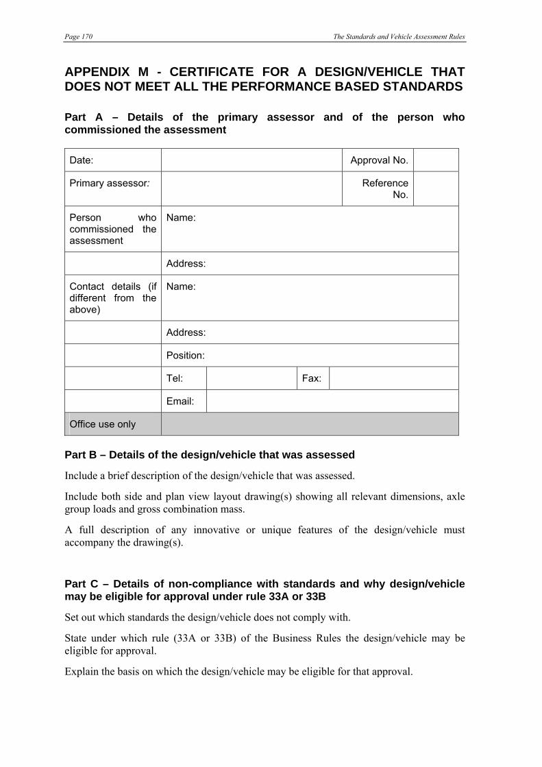
Page 170 The Standards and Vehicle Assessment Rules
APPENDIX M - CERTIFICATE FOR A DESIGN/VEHICLE THAT DOES NOT MEET ALL THE PERFORMANCE BASED STANDARDS Part A – Details of the primary assessor and of the person who commissioned the assessment Date: Approval No.
Primary assessor: Reference No.
Person who commissioned the assessment
Name:
Address:
Contact details (if different from the above)
Name:
Address:
Position:
Tel: Fax:
Email:
Office use only
Part B – Details of the design/vehicle that was assessed
Include a brief description of the design/vehicle that was assessed.
Include both side and plan view layout drawing(s) showing all relevant dimensions, axle group loads and gross combination mass.
A full description of any innovative or unique features of the design/vehicle must accompany the drawing(s).
Part C – Details of non-compliance with standards and why design/vehicle may be eligible for approval under rule 33A or 33B
Set out which standards the design/vehicle does not comply with.
State under which rule (33A or 33B) of the Business Rules the design/vehicle may be eligible for approval.
Explain the basis on which the design/vehicle may be eligible for that approval.

The Standards and Vehicle Assessment Rules Page 171
Part D – Recommended overall performance level After conducting a global assessment of the performance levels achieved by the design/vehicle with respect to each standard for which a performance level is relevant, and on the assumption that the design/vehicle is eligible for approval, I recommend that the *design/*vehicle be given an overall classification level of– Level 1 Level 2 Level 3 Level 4. Part E – Details of prescriptive requirements from which exemption needed In my opinion, the vehicle, or a vehicle built to the design, will require exemption from the following prescriptive requirements – [tick one or more of the following] clause 64 (Axle configuration) clause 65 (Relation between axles in a group) clause 66 (Width)
clause 67 (Length of single motor vehicles)
clause 68 (Length of single trailers)
clause 69 (Length of combinations)
clause 70 (Rear overhang)
clause 71 (Trailer drawbar length)
clause 72 (Height)
clauses 169 (b) and (c) (Attachment of couplings and drawbar eyes on long road trains);
clause 171 (Tow coupling overhang on long road trains)
the following ADRs: Rule 43, clause 6.1 (Length) Rule 43, clause 6.2 (Rear overhang)(other than clause 6.2.1) Rule 43, clause 6.2.1 (Rear overhang) Rule 43, clause 6.3 (Height) Rule 43, clause 6.5 (Width) Rule 43, clause 9.4 (Retractable axles) Rule 43, clause 9.5 (Retractable axles) Rule 62, clause 5.3 (Tow coupling overhang) Rule 63, clause 63.5.1 (Tow coupling location)
Part F – Details of the results of the assessment against infrastructure
standards Attach results of the assessments conducted in accordance with Appendix A.

Page 172 The Standards and Vehicle Assessment Rules
Part G – Details of the results of the assessment against safety standards If any part of the assessment has been undertaken by numerical simulation, attach Table 36. If any part of the assessment has been undertaken by testing, attach Table 55. If any part of the assessment relies on an assessment made by one or more other assessors, attach copy of certificate relied on from those other assessments. Part H – Details of vehicle physical characteristics Attach the Vehicle Certification Information (Appendix G) for the vehicle. Part I – Details of sensitivity testing If any risk sensitivity testing was undertaken, attach copy of completed Appendix H or I or both, as the case may be. Part J – Details of critical characteristics Include a list of the vehicle physical characteristics that are most important to the capability of the vehicle, or a vehicle built to the design, to comply with, or to continue to comply with, the standards. Part K – Details of vehicle operating conditions Attach Appendix J (Information and recommendations concerning vehicle operating conditions). If recommending that an operator, as a national operating condition, be required to have a quality system to control the performance of the vehicle, the recommendation must include the items that must be specified in the quality system. Part L – Details of assumptions relied on Include a list of assumptions on which reliance has been placed in conducting the assessment, or in forming an opinion in relation to the design or vehicle. Part M – Certification I certify: (a) that in my opinion, based on the assessment I have undertaken:
The Standards and Vehicle Assessment Rules Page 173
*(i) although a vehicle built to the design set out under Part B will not meet all
the infrastructure and safety standards set out in Appendices A and C of The Standards and Vehicle Assessment Rules, it may be eligible for approval under rule 33A or 33B of the Review Panel Business Rules for the reasons set out in Part C;
*(ii) the vehicle described under Part B does not meet all the infrastructure and
safety standards set out in Appendices A and C of The Standards and Vehicle Assessment Rules, but it may be eligible for approval under rule 33A or 33B of the Review Panel Business Rules for the reasons set out in Part C;
(* omit whichever paragraph does not apply)
(b) that all details given in Parts A to L are true and correct or, in the case of an
opinion, accurately express my opinion.
Name:
Signature:
Date:

PO Box 492Fortitude Valley QLD 4006
Ph: 1300 MYNHVR (1300 696 487)Fx: (07) 3309 8777Email: [email protected]
www.nhvr.gov.au 0020
/01-
2013