pavement edge treatment - washington state … · figure 40. close-up of pavement edge treatment on...
TRANSCRIPT

January 2013Keith W. Anderson Terry BerendsMark RussellJeff S. UhlmeyerJim WestonChad SimonsonChris DamatioHien Trinh
WA-RD 798.1
Office of Research & Library Services
WSDOT Research Report
Pavement Edge Treatment

Experimental Feature Report __________________________________________________________
Post-Construction Report Experimental Feature WA 11-01
Pavement Edge Treatment
Contract 8017, SR 395 Lee Road to Junction I-90
Contract 8116, SR 410
Twin Creek to Mather Memorial Park Pull-Off Paving
Contract 8241, SR 21 Curlew State Park to North of Rin Con Creek
Contract 8271, SR 542
Fossil CR to Wells CR RD Vic Paving
Engineering and Regional Operations Construction Division
State Materials Laboratory

Experimental Feature Report __________________________________________________________
January 2013 ii
1. REPORT NO.
WA-RD 798.1
2. GOVERNMENT ACCESSION NO. 3. RECIPIENT'S CATALOG NO.
4. TITLE AND SUBTITLE
Pavement Edge Treatment
5. REPORT DATE
January 2013 6. PERFORMING ORGANIZATION CODE
WA 11-01 7. AUTHOR(S)
Keith W. Anderson, Terry Berends, Mark Russell, Jeff S. Uhlmeyer, Jim Weston, Chad Simonson, Chris Damitio, and Hien Trinh
8. PERFORMING ORGANIZATION REPORT NO.
9. PERFORMING ORGANIZATION NAME AND ADDRESS
Washington State Department of Transportation
Materials Laboratory, MS-47365
Olympia, WA 98504-7365
10. WORK UNIT NO.
11. CONTRACT OR GRANT NO.
12. SPONSORING AGENCY NAME AND ADDRESS
Washington State Department of Transportation Transportation Building, MS 47372 Olympia, Washington 98504-7372 Project Manager: Kim Willoughby, 360-705-7978
13. TYPE OF REPORT AND PERIOD COVERED
Post-Construction Report 14. SPONSORING AGENCY CODE
15. SUPPLEMENTARY NOTES
This study was conducted in cooperation with the U.S. Department of Transportation, Federal Highway Administration. 16. ABSTRACT
Four projects were built over two construction seasons using special devices attached to the paving machine that produces a 30º slope on the outside pavement edge instead of the near vertical drop-off common with conventional paving equipment. This pavement edge treatment allows vehicles that leave the roadway a gentler slope to navigate when remounting the pavement.
The projects used four types of devices; (1) the TransTech Shoulder Wedge MakerTM, (2) the Advant-EdgeTM, (3) the Carlson Safety Edge End Gate, and (4) a contractor built device. All of the devices were able to produce a finished pavement slope that was close to the 30º angle recommended by FHWA.
The projects will be monitored for five years to measure the functional performance of the edge treatment and possible reductions in collisions caused by drivers trying to re-enter the roadway after losing control and running off the road.
17. KEY WORDS
Safety EdgeSM, Slope, HMA, Advant-EdgeTM, TransTech Shoulder Wedge MakerTM, Troxler Safety Slope™, Carlson Safety Edge End Gate, pavement edge treatment
18. DISTRIBUTION STATEMENT
19. SECURITY CLASSIF. (of this report)
None
20. SECURITY CLASSIF. (of this page)
None
21. NO. OF PAGES
48
22. PRICE

Experimental Feature Report __________________________________________________________
January 2013 iii
DISCLAIMER
The contents of this report reflect the views of the authors, who are responsible for the
facts and the accuracy of the data presented herein. The contents do not necessarily reflect the
official views or policies of the Washington State Department of Transportation or the Federal
Highway Administration. This report does not constitute a standard, specification, or regulation.

Experimental Feature Report __________________________________________________________
January 2013 iv
TABLE OF CONTENTS
Introduction ..................................................................................................................................... 1 Safety EdgeSM Description .............................................................................................................. 1 Need ................................................................................................................................................ 4 Literature Review............................................................................................................................ 5
Device Used ................................................................................................................................ 6 Device Operation ........................................................................................................................ 6 Slope Angle ................................................................................................................................. 6 Compaction ................................................................................................................................. 7 Pavement Segregation ................................................................................................................. 7 Pavement Thickness.................................................................................................................... 7 Summary of Demonstration Projects .......................................................................................... 7
Application ...................................................................................................................................... 8 Devices Used to Construct Pavement Edge Treatment .................................................................. 9
TransTech Systems, Inc. ............................................................................................................. 9 Troxler....................................................................................................................................... 10 Carlson Paving Products, Inc. ................................................................................................... 11 Advant-Edge Paving Equipment............................................................................................... 12
WSDOT Projects .......................................................................................................................... 14 Contract 8017, SR 395, Lee Road to Junction I-90 .................................................................. 14 Contract 8116, SR 410, Twin Creek to Mather Memorial Park Pull-Off Paving ..................... 18 Contract 8241, SR 21, Curlew State Park to N of Rin Con Creek Rd - Paving ....................... 24 Contract 8271, SR 542, Fossil Cr to Wells Cr Rd Vic - Paving ............................................... 27
Summary of Findings .................................................................................................................... 30 Evaluation of the Process and the Devices ................................................................................... 31 Future Research ............................................................................................................................ 32 References ..................................................................................................................................... 32 Appendix A FHWA Demonstration Projects Summary Data ..................................................... 33 Appendix B Contract Special Provisions ..................................................................................... 35 Appendix C Experimental Feature Work Plan ............................................................................ 37

Experimental Feature Report __________________________________________________________
January 2013 v
LIST OF FIGURES
Figure 1. Typical drop-off crash with tire scrubbing. (FHWA) ................................................... 2 Figure 2. Safety EdgeSM detail. (FHWA Safety Edge PowerPoint) ............................................. 2 Figure 3. Without a Safety EdgeSM. (FHWA Safety Edge PowerPoint) ...................................... 3 Figure 4. With a Safety EdgeSM. (FHWA Safety Edge PowerPoint) ........................................... 3 Figure 5. Vertical drop off at pavement edge. (FHWA Safety EdgeSM PowerPoint) ................... 3 Figure 6. Sloping edge produced by pavement edge hardware. (FHWA Safety EdgeSM PowerPoint)..................................................................................................................................... 3 Figure 7. Pavement edge without the Safety EdgeSM in foreground and with the Safety EdgeSM in the background. (FHWA Safety Edge PowerPoint) ................................................................... 4 Figure 8. TransTech Shoulder Wedge Maker™ (SWM). Note compound angle of the wedge face. (FHWA, Madison Co., WI) ................................................................................................. 10 Figure 9. Troxler SafeTSlope™ Edge Smoother. ........................................................................ 11 Figure 10. Carlson Safety Edge End Gate hardware. (FHWA, Madison Co., WI) .................... 12 Figure 11. Carlson Safety Edge End Gate in use. (FHWA, Menominee, WI) ........................... 12 Figure 12. The Advant-Edger™ creates a tapered 30° safety edge along the shoulder of the road........................................................................................................................................................ 13 Figure 13. The Advant-Edge Ramp Champ™ forms a tapered safety edge or a longitudinal center lane joint. ............................................................................................................................ 13 Figure 14. Advant-Edge™ mounted on a paver. Unit is designed to automatically adjust to shoulder elevation changes (driveways and intersections). .......................................................... 13 Figure 15. SR 395, Lee Road to Junction I-90 location map. ...................................................... 15 Figure 16. SR 395 before overlay. Note wide stable shoulder. .................................................. 15 Figure 17. Paver forming and compacting pavement edge treatment. ........................................ 15 Figure 18. Close-up of paver screed. ........................................................................................... 16 Figure 19. Close-up of roller hardware. ....................................................................................... 16 Figure 20. Close-up of sloped pavement edge showing top of slope at existing pavement edge.16 Figure 21. View of rolled pavement edge treatment. ................................................................... 16 Figure 22. Distant view of paver with edge rolling hardware. .................................................... 16 Figure 23. Angle of sloped pavement edge. Note the uniform compaction. .............................. 16 Figure 24. Finished pavement with shoulder material in place. .................................................. 17 Figure 25. Finished pavement with shoulder material in place. .................................................. 17 Figure 26. SR 410, Twin Creek to Mather Memorial Park Pull-Out Paving location map. ........ 19 Figure 27. SR 410 prior to construction....................................................................................... 19 Figure 28. Side view of TransTech hardware. ............................................................................. 19 Figure 29. End view of TransTech pavement edge hardware without the roller. ........................ 20 Figure 30. Pavement edge formed by the TransTech hardware prior to adding the roller. Note open texture of the HMA. ............................................................................................................. 20 Figure 31. Pavement edge treatment after addition of a roller behind the paver. ........................ 20 Figure 32. Roller added to compact the vertical edge at the top of the slope. ............................. 20 Figure 33. Roller added to compact the vertical edge at the top of the slope. ............................. 20

Experimental Feature Report __________________________________________________________
January 2013 vi
Figure 34. Finished pavement with dressed shoulders. ............................................................... 20 Figure 35. Dig out showing slope of pavement edge. .................................................................. 21 Figure 36. Shoulder material put back in place. .......................................................................... 21 Figure 37. Pavement edge treatment close-up one year after construction. ................................ 23 Figure 38. Pavement edge treatment on SR 410 one year after construction. ............................. 23 Figure 39. Another photo of the SR-410 pavement edge treatment one year after construction. 23 Figure 40. Close-up of pavement edge treatment on SR 410 one year after construction.
Shows some exposure of pavement edge treatment. .................................................. 23 Figure 41. SR 21, Curlew State Park to North of Rin Con Creek location map.......................... 24 Figure 42. Advant-EdgeTM used to produce the pavement edge treatment. ................................ 25 Figure 43. Pavement edge treatment produced by the Advant-EdgerTM. .................................... 25 Figure 44. Pavement edge treatment on SR 21. ........................................................................... 25 Figure 45. Close-up of edge treatment slope. .............................................................................. 25 Figure 46. Side view of edge treatment. ...................................................................................... 25 Figure 47. Another view of the edge treatment. .......................................................................... 25 Figure 48. Edge treatment and shoulder area. .............................................................................. 26 Figure 49. Close-up of edge treatment slope. .............................................................................. 26 Figure 50. Slope of edge treatment across a road approach. ....................................................... 26 Figure 51. Closer view of slope of edge treatment. ..................................................................... 26 Figure 52. SR 542, Fossil Creek to Wells Creek Road Vicinity location map. ........................... 28 Figure 53. Side view of Carlson end gate. ................................................................................... 28 Figure 54. Mix passing through the end gate. .............................................................................. 28 Figure 55. Pavement edge treatment produced by the Carlson end gate. .................................... 29 Figure 56. Slope indicator device on the edge treatment. Slope does not appear to be
compacted. .................................................................................................................. 29 Figure 57. Close-up of slope indicator. ........................................................................................ 29 Figure 58. View showing uniform appearance of edge treatment. .............................................. 29 Figure 59. Pavement edge treatment next to guardrail. ............................................................... 29 Figure 60. Pavement edge treatment next to guardrail. ............................................................... 29
LIST OF TABLES
Table 1. WSDOT Projects with pavement edge treatment. ......................................................... 14 Table 2. SR 395 edge treatment slope angle before and after compaction. ................................. 18 Table 3. SR 410 edge treatment slope angle before and after compaction. ................................. 22 Table 4. SR 410 edge treatment slope angle after compaction MP 40.30 to 40.59. .................... 22 Table 5. After compaction slope measurements for SR 21. ........................................................ 27 Table 6. Slope measurements on the finished pavement on SR 542. .......................................... 30 Table 7. Average compacted slope angle for each project. ......................................................... 31
Experimental Feature Report __________________________________________________________
January 2013 1
Introduction
Safety EdgeSM is one of the safety enhancements being promoted through the Federal
Highway Administration’s (FHWA) Every Day Counts (EDC) program. The Every Day Counts
program identifies and deploys innovative technologies that are aimed at shortening project
delivery, enhancing safety, or protecting the environment. The Safety EdgeSM pavement edge
treatment enhances safety through a modification to asphalt paving equipment that result in a
sloped edge in place of a vertical edge at the outside shoulder. WSDOT is embracing the EDC
program by constructing a number of demonstration projects which will be monitored for
constructability, pavement edge stability and durability, operational characteristics, and collision
reduction.
Safety EdgeSM Description
If a vehicle leaves the roadway in a location where the pavement edge drops off
vertically, a driver may overcorrect as they re-enter the roadway and this overcorrection can
cause a loss of vehicle control and lead to a serious collision. When drop offs are in the range of
four inches, the potential exists for a vehicle’s front tire to scrub against the pavement edge and
not be able to return to the road surface (Ivey and Sicking, 1986). In these conditions drivers
may increase turning forces in an effort to overcome the pavement edge drop. When the tire
overcomes the friction forces created by the tire-pavement interaction, the vehicle may return to
the road surface abruptly and with excess angle. Once the vehicle re-enters the roadway the
sharp turning angle of the front tires may result in the driver losing control of the vehicle which
can cause it to rollover or swerve into oncoming traffic (see Figure 1).

Experimental Feature Report __________________________________________________________
January 2013 2
Figure 1. Typical drop-off crash with tire scrubbing. (FHWA)
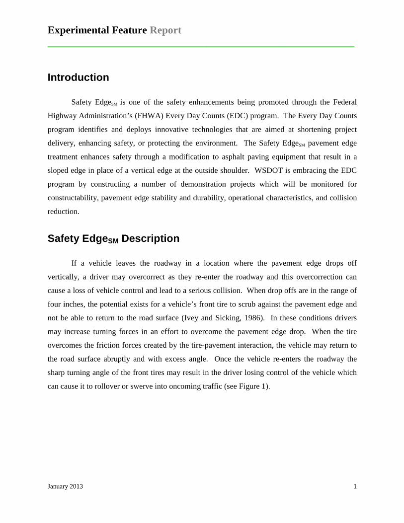
The Safety EdgeSM pavement edge treatment provides a non-vertical wedge at the edge of
the pavement which reduces the steering forces needed for re-entering the roadway. With this
treatment, the pavement edge is sloped at a 30º angle (see Figure 2). The presence of a slope
instead of a vertical face makes it easier for a vehicle to re-enter the roadway after inadvertently
driving off the edge of the pavement. Figures 3 and 4 are diagrams of a pavement edge without
and with the pavement edge treatment. Figures 5 and 6 are photos of a pavement with a vertical
edge and one with the pavement edge treatment. Figure 7 shows a pavement under construction
with no edge treatment and with edge treatment.
Figure 2. Safety EdgeSM detail. (FHWA Safety Edge PowerPoint)

Experimental Feature Report __________________________________________________________
January 2013 3
Figure 3. Without a Safety EdgeSM. (FHWA Safety Edge PowerPoint)
Figure 4. With a Safety EdgeSM. (FHWA Safety Edge PowerPoint)
Figure 5. Vertical drop off at pavement edge. (FHWA Safety EdgeSM PowerPoint)
Figure 6. Sloping edge produced by pavement edge hardware. (FHWA Safety EdgeSM PowerPoint)
Experimental Feature Report __________________________________________________________
January 2013 4
Figure 7. Pavement edge without the Safety EdgeSM in foreground and with the Safety EdgeSM in the background. (FHWA Safety Edge PowerPoint)
Need
The Strategic Highway Safety Plan, adopted in 1998 by the American Association of
State Highway and Transportation Officials (AASHTO), identified 22 goals to pursue in order to
reduce the number of crashes and fatalities on our nation’s highways. The goals included
minimizing the consequences of leaving the road and reducing head-on and across median
crashes (AASHTO, 1998). National Highway Traffic Safety Administration (NHTSA) statistics
from 2009 showed that of all the fatal accidents, approximately 53% can be attributed to vehicles
leaving the roadway (NHTSA, 2009). A reduction in roadway departures fatalities would
significantly impact the total number of annual fatalities, which is the goal of FHWA in
promoting the use of the Safety EdgeSM (FHWA Safety EdgeSM Web Site).

Experimental Feature Report __________________________________________________________
January 2013 5
Literature Review
Texas Transportation Institute (TTI) did pioneering work in the 1980’s on an improved
pavement edge configuration. Their research found that drivers rated a 45º wedge as a much
easier pavement edge to remount than either the vertical or rounded edge normally found on
pavement edges. The TTI study was criticized as not being representative of real world
conditions because the participants were instructed to drive off the pavement edge rather than
collecting data from drivers unknowingly putting themselves in the position of remounting a
vertical pavement edge (Zimmer and Ivey, 1983).
A Federal Highway Administration (FHWA) pooled fund project initiated the
implementation of the Safety EdgeSM. The eight states (California, Colorado, Georgia, Indiana,
Mississippi, New York, North Carolina and Utah) constructed projects with the Safety EdgeSM
and participated in a multiyear performance evaluation. The effort focused on rural two-lane
roadways with paved and unpaved shoulders. A total of 377 sites in Georgia and Indiana were
selected and accident data was collected over a three year period. The researchers looked at the
effectiveness, cost, and benefit-cost of the Safety EdgeSM treatment (FHWA, 2011).
The analysis of the crash data determined that the use of the safety edge resulted in
approximately a 5.7 percent reduction in total crashes. This result was not statistically
significant; however, the results obtained were always in a positive direction. The statistical
analysis of fatal and injury crashes were too variable to draw conclusions. Overall project costs
and the overall cost of asphalt resurfacing materials did not increase for the projects with the
treatment as compared to projects without the treatment. Computations based on the volume of
asphalt material used to form the safety edge suggest added costs in the range of $536 to $2,145
per lane mile for both sides of the roadway. Benefit-cost analysis based on the estimated 5.7
percent crash reduction effectiveness found that the safety edge treatment is so inexpensive that
it is highly cost-effective for application in a broad range of applications on two-lane highways
(FHWA, 2011).
Eleven FHWA sponsored demonstration projects were constructed in ten states under the
EDC program in 2010 and 2011. The individual field reports from these demonstration projects

Experimental Feature Report __________________________________________________________
January 2013 6
can be seen by clicking here. A brief summary of the field reports follows with more complete
information tabulated in Appendix A.
Device Used
Five different devices were used on 11 projects to construct the Safety EdgeSM.
• TransTech Shoulder Edge Maker (7 projects) • Avant-Edge (3 projects) • Carlson End Gate (2 projects) • Troxler SafeTSlope (1 project) • Home Made Devices (2 projects, one Iowa, one North Carolina)
Device Operation
The major complaint with the devices, with the exception of the Carlson End Gate, center
on the difficulty in quickly raising or lowering the devices when paving across intersections or in
areas with higher or lower longitudinal profiles. Contractors and state inspection personnel
recommended the development of automated devices to eliminate this problem. Most of the
devices now employ a spring mechanism that allows the device to move vertically when
encountering obstacles. The Carlson End Gate moves with the screed and therefore does not
need to be adjusted.
Slope Angle
The end product of the use of the safety edge devices is a sloped edge. The average slope
produced by each device was measured to be as follows:
• TransTech (37°) on seven projects • Avant-Edge (50°) on three projects • Troxler (28°) on one project • Carlson (31°) on two projects • NCDOT contractor built device (36°) on one project

Experimental Feature Report __________________________________________________________
January 2013 7
Compaction
Densities and air void contents immediately adjacent to the Safety EdgeSM are compared
to the same measurements three feet away from the safety edge to determine the degree of
compaction of the treated pavement. The results are as follows:
• Higher densities and lower air voids near the Safety EdgeSM (4 projects). • Slightly higher densities and lower air voids near the Safety EdgeSM (2 projects). • Densities and air voids no difference near the Safety EdgeSM (2 projects). • Lower densities and higher air voids near the Safety EdgeSM (1 project).
The higher densities and lower air voids were directly correlated to the amount of
compactive effort applied to the Safety EdgeSM. On the one project that recorded lower densities
the roller operators were instructed to avoid rolling the edge because it caused the slope angle to
substantially increase.
Pavement Segregation
Segregation was noted in the safety edge treatment pavement as follows:
• No segregation (6 projects) • Minor segregation (2 projects) • Interior segregation (1 project)
Pavement Thickness
The thickness of the pavement for each of the projects was as follows:
• 1.5 inches (4 projects) • 2.0 inches (4 projects) • Multiple lifts (1 project)
The thicker the pavement the easier it is to create the safety edge treatment, however, a thicker
lift also requires more compactive effort to achieve maximum density.
Summary of Demonstration Projects
The demonstration projects used all of the available Safety EdgeSM devices with the
TransTech Shoulder Edge Maker used on the most projects. Two projects used devices
developed by the paving contractor. The major complaint on the devices was the difficulty in

Experimental Feature Report __________________________________________________________
January 2013 8
quickly adjusting the device when encountering changes in longitudinal profile of the pavement
or intersections and as a result automation of the devices was recommended. The edge formed
by the various devices varied in slope angle from 28 to 50º with the Avant-Edger producing the
highest average angle at 50º and Troxler the lowest average at 28º. The TransTech device, used
on seven projects, produced an average slope angle of 37º. The compaction of the pavement at
the safety edge was higher or slightly higher than the pavement in the remainder of the mat in six
of the nine projects, the same in two of the nine, and lower in one of the nine projects.
Segregation of the asphalt material in the Safety EdgeSM area was not found in a majority of the
projects (7 out of 9) and only a minor amount in two of the nine projects. The depth of the
pavement places on the nine projects was equally split between 1.5 inches and 2.0 inches, with
four projects in each category. The remaining project had multiple lifts with the top lift being
1.5 inches.
Montana Department of Transportation (MDT) participated in the demonstration projects
by reviewing their 25 years of constructing tapered edges on their roadways. The tapered edge is
typically constructed at a 6:1 (9.5° angle) and is formed by attaching a strike-off plate to the
paver that strikes off the edge and pulls the excess material back into the screed. The review
determined that their practice performs very well and produces pavement edges that are durable
with no significant edge breakup. Opportunities were identified for the selective use of the
Safety EdgeSM on narrow roads, steep grades and curve widening. The conclusion arrived at by
the reviewers was that the MDT tapered edge practice should be acknowledged as being an
acceptable alternative to the Safety EdgeSM.
Application
WSDOT typically paves the shoulder on state highways to improve the driving surface
for errant vehicles. The widths of paved shoulders on WSDOT highways vary between one and
ten feet depending on route and location. Surfacing material is then used to finish the shoulder
slope flush with the top of the paved surface, which mitigates shoulder pavement edge drop-offs.
However, over time a vertical edge may be present due to erosion or wheel encroachment,
especially along curves. FHWA has determined that the Safety EdgeSM treatment is particularly

Experimental Feature Report __________________________________________________________
January 2013 9
beneficial on two-lane roads with unpaved shoulders. It allows drivers who drift off the highway
to return to the road safely. It is expected that as a result the number of crashes and fatal
collisions will be reduced. Its benefits are highlighted below:
• Reduces crashes and saves lives by mitigating pavement edge drop-off • Is a low cost, systematic improvement applied during paving • Improves durability by reducing edge raveling
Devices Used to Construct Pavement Edge Treatment
A number of manufacturers make hardware that forms the sloping pavement edge. All of these
devices are adjusted manually; however, the size and coarse threads of the cranking mechanism
do not facilitate quick adjustments. Contractors have been making modifications to these
devices to better fit their equipment and to simplify the operation of this device. One
modification has been to mount an electric drill on the device to quickly adjust the shoe height at
driveways, mailboxes and other obstacles. Contractors worry about the adjustment speed
because if the toe of the shoe is not above the driveway or other obstacle, the force of the paver
will rip the shoe off the paver and likely disrupt the screed alignment. It is a good idea for the
operator to give himself a buffer space initially until he gets more familiar with the speed of the
crank in relation to the speed of the paver (FHWA Safety EdgeSM Web Site).
TransTech Systems, Inc.
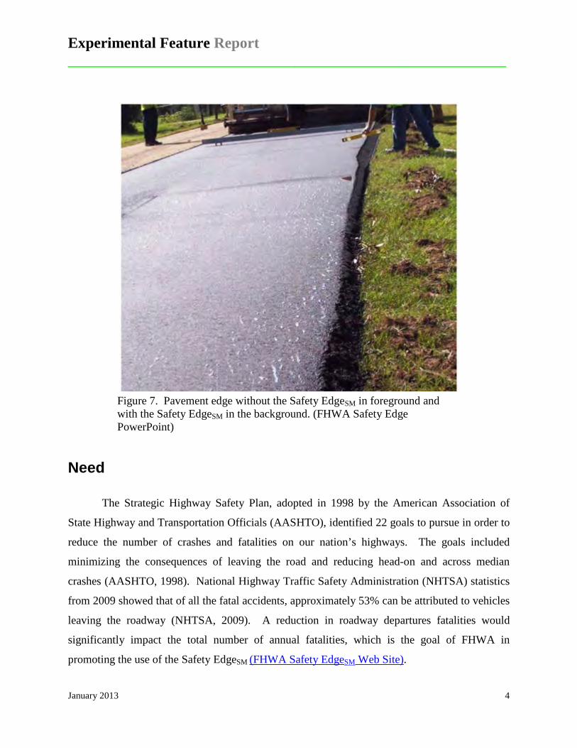
The TransTech Shoulder Wedge Maker™ (SWM) mounts directly on the paver screed
extension against the end gate (see Figure 8). An internal spring holds the device down on the
road surface and this pressure in combination with the compound angled face compacts the mat
as the paver moves forward. The SWM is delivered as a pair with both right-hand and left-hand
versions for paving with traffic or against traffic. TransTech also markets a notched wedge
device for longitudinal joint formation.
Experimental Feature Report __________________________________________________________
January 2013 10
Figure 8. TransTech Shoulder Wedge Maker™ (SWM). Note compound angle of the wedge face. (FHWA, Madison Co., WI)
Troxler
The Troxler SafeTSlope™ Edge Smoother is mounted on the paver screed extension
against the end gate (see Figure 9). A guide rail with a two-inch radius allows the device to ride
along the surface of the road shoulder following its contour. The two-inch radius helps the
transition when the device encounters an obstacle such as a driveway cut or road intersection. A
self-adjusting internal spring provides downward force to keep the guide rail in contact with the
shoulder surface. A 30º forming edge produces the smooth wedge fillet. A 45º compound angle
surface forces more asphalt mix under the device. An extended smoothing surface acts as a
Experimental Feature Report __________________________________________________________
January 2013 11
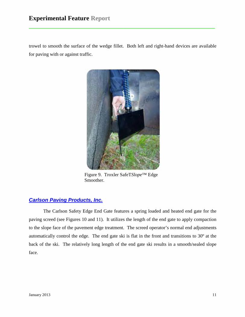
trowel to smooth the surface of the wedge fillet. Both left and right-hand devices are available
for paving with or against traffic.
Figure 9. Troxler SafeTSlope™ Edge Smoother.
Carlson Paving Products, Inc.
The Carlson Safety Edge End Gate features a spring loaded and heated end gate for the
paving screed (see Figures 10 and 11). It utilizes the length of the end gate to apply compaction
to the slope face of the pavement edge treatment. The screed operator’s normal end adjustments
automatically control the edge. The end gate ski is flat in the front and transitions to 30º at the
back of the ski. The relatively long length of the end gate ski results in a smooth/sealed slope
face.

Experimental Feature Report __________________________________________________________
January 2013 12
Figure 10. Carlson Safety Edge End Gate hardware. (FHWA, Madison Co., WI)
Figure 11. Carlson Safety Edge End Gate in use. (FHWA, Menominee, WI)
Advant-Edge Paving Equipment
The Advant-Edge™ attaches to the screed extension and shapes the edge to a 30º tapered
angle (Figures 12 and 14). It automatically adjusts to changes in shoulder elevations (i.e.
driveways) via its internal spring. The Advant-Edge™ is reversible so that it may be attached to
either side of the paving machine. A new model called the Ramp Champ™ is designed to create
either a safety edge or a tapered longitudinal center lane joint (Figure 13). It is also spring
loaded to automatically adjust for changes in shoulder elevation. The slope of the safety edge is
adjustable from 5º to 30º and its forming surfaces (shoes) are detachable permitting the same unit
to create a variety of edge profiles.

Experimental Feature Report __________________________________________________________
January 2013 13
Figure 12. The Advant-Edge™ creates a tapered 30° safety edge along the shoulder of the road.
Figure 13. The Advant-Edge Ramp Champ™ forms a tapered safety edge or a longitudinal center lane joint.
Figure 14. Advant-Edge™ mounted on a paver. Unit is designed to automatically adjust to shoulder elevation changes (driveways and intersections).

Experimental Feature Report __________________________________________________________
January 2013 14
(Note: The Safety EdgeSM will be referred to as the “pavement edge treatment” from this point on in the report.)
WSDOT Projects
As of September 2012, WSDOT has completed 4 demonstration projects that have
incorporated the pavement edge treatment device. Each of the 4 projects used a different device
on the paver to create the pavement edge treatment. The projects and the type of devices used on
each one are listed in Table 1:
Table 1. WSDOT Projects with pavement edge treatment.
Year Contract No. SR Project Device Used
2011 8017 395 Lee Road to Junction I-90 Contractor built screed and roller hardware
2011 8116 410 Twin Creek to Mather Memorial Park Pull-Off Paving
TransTech Shoulder Wedge Maker™ and contractor built roller hardware
2012 8241 21 Curlew State Park to North of Rin Con Creek Advant-Edge™
2012 8271 542 Fossil Cr. To Wells Cr. Rd. Vic. Paving Carlson Safety Edge End Gate
Contract 8017, SR 395, Lee Road to Junction I-90
Contract 8017 improved 22.50 miles of southbound SR 395 from MP 72.36 to MP 94.85
between Connell and the junction of I-90 at Ritzville, Washington as shown in the project
location map (Figure 15). The pavement edge treatment was added to the project via a change
order. The Contractor (Central Washington Asphalt Inc.) electing to build a special screed and
edge rolling hardware. The outside, passing lane was planned 0.15 ft. prior to the placement of
an equal amount of HMA Class 1/2 inch. The roadway was then paved shoulder to shoulder
with 0.15 ft. of HMA Class 1/2 inch using the pavement edge treatment on both shoulders except
where there was guardrail or curbing. The paving occurred in the spring of 2011.

Experimental Feature Report __________________________________________________________
January 2013 15
Figure 15. SR 395, Lee Road to Junction I-90 location map.
Figures 16 through 25 show the roadway prior to construction, the construction operation
and formation of the pavement edge treatment, and the finished product.
Figure 16. SR 395 before overlay. Note wide stable shoulder.
Figure 17. Paver forming and compacting pavement edge treatment.

Experimental Feature Report __________________________________________________________
January 2013 16
Figure 18. Close-up of paver screed. Figure 19. Close-up of roller hardware.
Figure 20. Close-up of sloped pavement edge showing top of slope at existing pavement edge.
Figure 21. View of rolled pavement edge treatment.
Figure 22. Distant view of paver with edge rolling hardware.
Figure 23. Angle of sloped pavement edge. Note the uniform compaction.

Experimental Feature Report __________________________________________________________
January 2013 17
Figure 24. Finished pavement with shoulder material in place.
Figure 25. Finished pavement with shoulder material in place.
Measurements were taken of the pavement edge angle at various locations before and
after compaction of the edge. The results are summarized in Table 2. The average final slope
angle of the compacted slopes at 23º misses the 30º goal on the good side since it is a much
flatter slope and would be easier to mount by a vehicle running off the road. The FHWA Design
and Construction Guide states that the recommended range for the slopes is 26 to 40 degrees
(FHWA Safety Edge Web Site).
One of the advantages of this particular roadway was a very firm stable shoulder area that
extended well beyond the pavement edge. This allowed the Contractor to retain the full width of
pavement by placing the pavement edge treatment on the shoulder area. Figures 37-39 show the
pavement edge treatment on top of the stable gravel shoulder area.

Experimental Feature Report __________________________________________________________
January 2013 18
Note: Heights have been adjusted for the slope of the pavement surface.
Contract 8116, SR 410, Twin Creek to Mather Memorial Park Pull-Off Paving
The second project using the pavement edge treatment was located on SR 410 between
Enumclaw and the junction of SR 123 with its center roughly around Greenwater, Washington.
The project limits extended for 9.2 miles; however, two large paving exceptions reduced the total
mileage to 5.32 miles. The roadway was paved shoulder to shoulder with 0.15 ft. of HMA Class
1/2 inch using the pavement edge treatment on both shoulders except where there was guardrail
or curbing. The pavement edge treatment was added as a Special Provision (Appendix B). The
Contractor, Tucci and Sons Inc., used a TransTech Shoulder Wedge Maker™ and a home-made
edge roller to form the pavement edge treatment. The treatment was only used between MP
35.50 and MP 37.00. The Contractor started without the roller but the slope was unacceptable so
they added the roller to improve compaction of the slope. The paving occurred in the summer of
2011.
Table 2. SR 395 edge treatment slope angle before and after compaction. Uncompacted Slopes Compacted Slopes
Height (in)
Length (in)
Slope (º)
Height (in)
Length (in)
Slope (º)
3.15 7.50 23 1.84 4.25 23 2.90 7.50 21 2.61 5.25 26 2.63 6.50 22 2.09 4.50 25 3.15 7.50 23 2.10 5.00 23 2.65 7.50 19 2.37 6.00 22 2.65 7.25 20 2.11 5.25 22 3.39 7.00 26 1.86 5.50 19 3.14 6.75 25 2.34 4.50 27
- - - 2.00 4.75 23 Average 22 Average 23

Experimental Feature Report __________________________________________________________
January 2013 19
Figure 26. SR 410, Twin Creek to Mather Memorial Park Pull-Out Paving location map.
Figures 27 through 36 show the roadway prior to construction, the construction operation
and formation of the pavement edge treatment, and the finished product.
Figure 27. SR 410 prior to construction. Figure 28. Side view of TransTech hardware.

Experimental Feature Report __________________________________________________________
January 2013 20
Figure 29. End view of TransTech pavement edge hardware without the roller.
Figure 30. Pavement edge formed by the TransTech hardware prior to adding the roller. Note open texture of the HMA.
Figure 31. Pavement edge treatment after addition of a roller behind the paver.
Figure 32. Roller added to compact the vertical edge at the top of the slope.
Figure 33. Roller added to compact the vertical edge at the top of the slope.
Figure 34. Finished pavement with dressed shoulders.

Experimental Feature Report __________________________________________________________
January 2013 21
Figure 35. Dig out showing slope of pavement edge.
Figure 36. Shoulder material put back in place.
This project had some areas where the pavement edge treatment could be placed outside
of the existing paved surface; however, there were some areas that the slope began immediately
at the edge of existing slope so this required a slight narrowing of the roadway surface.
Measurements were taken to determine the angle of pavement edge treatment at various
locations before and after compaction of the edge. The results are summarized in Table 3. The
measurements on the uncompacted edge averaged 30º with a range of values between 27 and 33º.
Two sets of measurements were made on the compacted slopes. The first set at unknown
mileposts averaged 40º with a range of 34 to 43º. The second set taken between MP 40.20 and
40.59 averaged 29º with a range of 26 to 31º.

Experimental Feature Report __________________________________________________________
January 2013 22
Table 3. SR 410 edge treatment slope angle before and after compaction. Uncompacted Slopes (MP 41.55 - MP
41.69) Compacted Slopes (milepost unknown)
Height (in)
Length (in)
Slope (º)
Height (in)
Length (in)
Slope (º)
3.50 7.00 27 2.05 2.50 39 3.00 5.00 31 2.05 2.25 42 3.25 5.00 33 2.31 2.75 40 3.5 6.75 27 2.31 3.00 38 2.5 4.00 32 2.06 2.75 37
Average 30 2.30 2.50 43 2.06 2.75 37 2.56 3.00 40 2.06 3.00 34 2.30 2.50 43 2.06 2.75 37 2.30 2.50 43 2.05 2.25 42
Average 40
Table 4. SR 410 edge treatment slope angle after compaction MP 40.30 to 40.59.
Slope Top Surface
(º)
Edge Slope (º)
Effective Edge Slope
(º)
Slope Top Surface
(º)
Edge Slope (º)
Effective Edge Slope
(º) 1 30 29 4 32 28 1 30 29 4 30 26 1 30 29 3 30 27 1 30 29 3 30 27 1 30 29 3 30 27 1 30 29 3 30 27 1 30 29 2 30 28 1 30 29 2 30 28 1 30 29 2 30 28 1 30 29 2 30 28 2 30 28 2 30 28 2 30 28 2 30 28 2 30 28 1 32 31 2 30 28 1 32 31 2 30 28 1 32 31 2 30 28 1 32 31 3 30 27 1 32 31 3 32 29 1 32 31 3 32 29 1 32 31 3 32 29 1 32 31
Average 29
Experimental Feature Report __________________________________________________________
January 2013 23
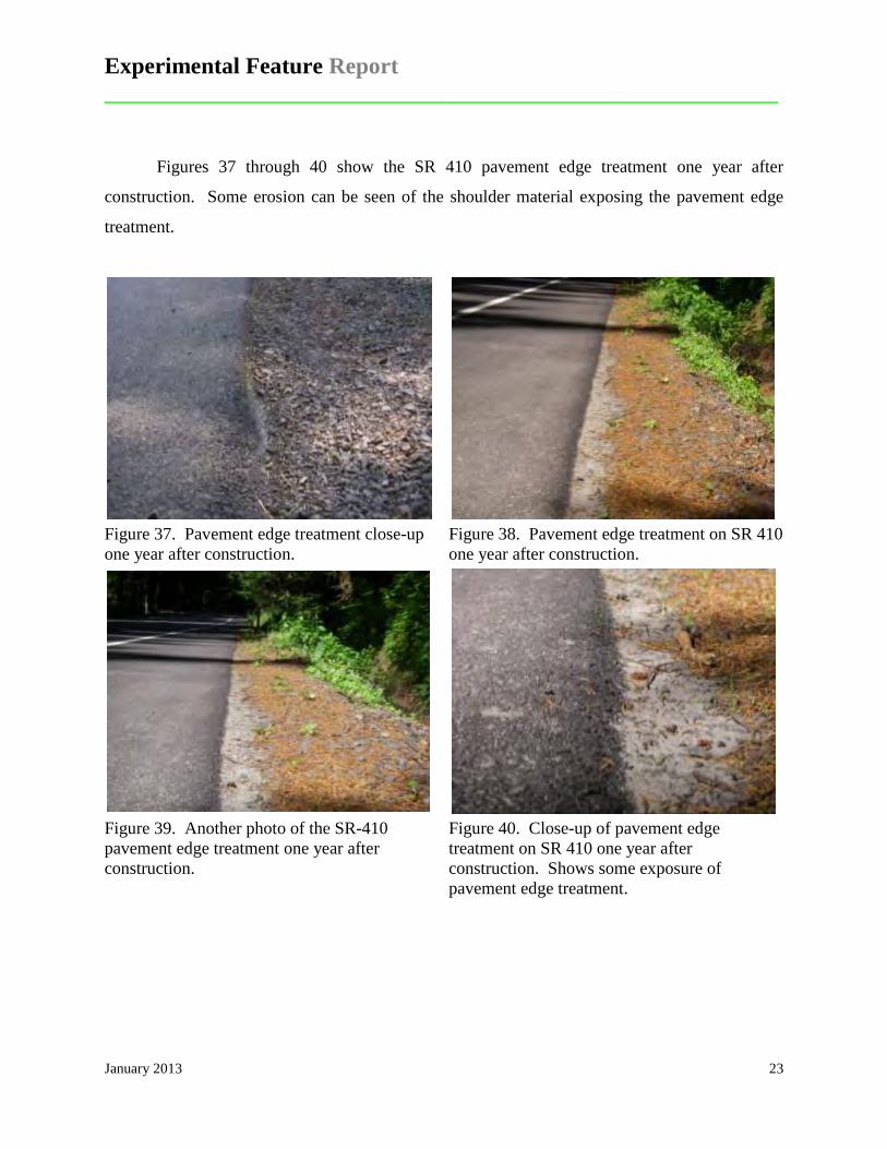
Figures 37 through 40 show the SR 410 pavement edge treatment one year after
construction. Some erosion can be seen of the shoulder material exposing the pavement edge
treatment.
Figure 37. Pavement edge treatment close-up one year after construction.
Figure 38. Pavement edge treatment on SR 410 one year after construction.
Figure 39. Another photo of the SR-410 pavement edge treatment one year after construction.
Figure 40. Close-up of pavement edge treatment on SR 410 one year after construction. Shows some exposure of pavement edge treatment.
Experimental Feature Report __________________________________________________________
January 2013 24
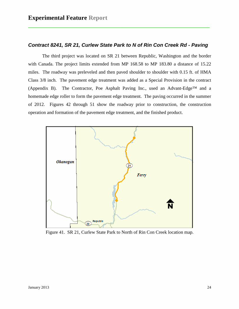
Contract 8241, SR 21, Curlew State Park to N of Rin Con Creek Rd - Paving
The third project was located on SR 21 between Republic, Washington and the border
with Canada. The project limits extended from MP 168.58 to MP 183.80 a distance of 15.22
miles. The roadway was preleveled and then paved shoulder to shoulder with 0.15 ft. of HMA
Class 3/8 inch. The pavement edge treatment was added as a Special Provision in the contract
(Appendix B). The Contractor, Poe Asphalt Paving Inc., used an Advant-Edge™ and a
homemade edge roller to form the pavement edge treatment. The paving occurred in the summer
of 2012. Figures 42 through 51 show the roadway prior to construction, the construction
operation and formation of the pavement edge treatment, and the finished product.
Figure 41. SR 21, Curlew State Park to North of Rin Con Creek location map.

Experimental Feature Report __________________________________________________________
January 2013 25
Figure 42. Advant-EdgeTM used to produce the pavement edge treatment.
Figure 43. Pavement edge treatment produced by the Advant-EdgeTM.
Figure 44. Pavement edge treatment on SR 21. Figure 45. Close-up of edge treatment slope.
Figure 46. Side view of edge treatment. Figure 47. Another view of the edge treatment.

Experimental Feature Report __________________________________________________________
January 2013 26
Figure 48. Edge treatment and shoulder area. Figure 49. Close-up of edge treatment slope.
Figure 50. Slope of edge treatment across a road approach.
Figure 51. Closer view of slope of edge treatment.
Measurements were taken at three locations to determine the angle of pavement edge
treatment after compaction of the edge. The results are summarized in Table 5. The average of
20º is well below the target value of 30º indicating the slopes are flatter making it easier for
vehicles to re-enter the roadway if they exited the pavement.

Experimental Feature Report __________________________________________________________
January 2013 27
Table 5. After compaction slope measurements for SR 21.
Height (in.)
Length (in.)
Degrees (º)
4 15.5 15 5 13 23 3 8.5 21 Average 20
Contract 8271, SR 542, Fossil Cr to Wells Cr Rd Vic - Paving
The fourth project was located on SR 542, the Mt. Baker Highway, between Glacier and
the end of the route. The project limits extended from MP 38.65 to MP 41.55 a distance of 2.90
miles, however, the first 0.43 miles were a paving exception; therefore, the total length of paving
was only 2.47 miles. The entire roadway was planed 0.15 inches shoulder to shoulder in
preparation for the paving. The pavement section consisted of 0.15 ft. of HMA Class 3/8 inch
over 0.08 inches of HMA Class 3/8 inch pre-leveling. The pavement edge treatment was added
as a Special Provision in the contract (Appendix B). The contract was awarded to Granite
Construction Inc. with paving scheduled for August of 2012. The Carlson End Gate was used to
form the pavement edge treatment on this project.
Experimental Feature Report __________________________________________________________
January 2013 28
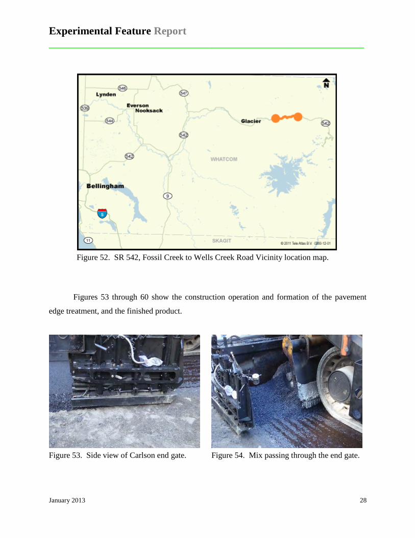
Figure 52. SR 542, Fossil Creek to Wells Creek Road Vicinity location map.
Figures 53 through 60 show the construction operation and formation of the pavement
edge treatment, and the finished product.
Figure 53. Side view of Carlson end gate. Figure 54. Mix passing through the end gate.

Experimental Feature Report __________________________________________________________
January 2013 29
Figure 55. Pavement edge treatment produced by the Carlson end gate.
Figure 56. Slope indicator device on the edge treatment. Slope does not appear to be compacted.
Figure 57. Close-up of slope indicator. Figure 58. View showing uniform appearance
of edge treatment.
Figure 59. Pavement edge treatment next to guardrail.
Figure 60. Pavement edge treatment next to guardrail.

Experimental Feature Report __________________________________________________________
January 2013 30
Table 6 lists the slope measurement made of the finished pavement using a slope
indicator gauge (Figures 56 and 57). The average of 28º meets the pavement edge goal of 30º
and none of the slopes fall out of FHWA’s 26 to 40º recommended range.
Table 6. Slope measurements on the finished pavement on SR 542.
Station Milepost Slope (º) 121+50 40.75 24.0 122+50 40.77 25.0 123+50 40.79 39.0 124+50 40.81 27.0 125+50 40.82 35.0 126+50 40.84 31.0 127+50 40.86 27.0 129+50 40.90 26.0 131+50 40.94 23.0 133+50 40.98 24.0
Average 28.0
Summary of Findings
All of the pavement edge devices were capable of producing a finished pavement that
met the FHWA’s goal of 30º (Table 7). The slope angles produced on the four WSDOT projects
which ranged from 20 to 30 degrees are generally lower and in the case of the Avant-EdgeTM and
TransTech significantly lower than those reported on the FHWA demonstration projects. As
previously noted, pavement edges produced by the Advant-EdgeTM had an average slope angle of
50º, by the TransTech an average of 37º, and by the Carlson End Gate an average of 31º on the
trial demonstration projects. It would appear that perhaps the design of the first two devices has
changed since the demonstration projects were built, or that contractors have become more adept
at using the devices to produce the desired slope angle.

Experimental Feature Report __________________________________________________________
January 2013 31
Table 7. Average compacted slope angle for each project.
Project Average Slope Angle (º) Device Used
SR 395, Lee Road to Junction I-90 23 Contractor built
SR 410, Twin Creek to Mather Memorial Park Pull-Off Paving 31 TransTech Shoulder
Wedge Maker™
SR 21, Curlew State Park to North of Rin Con Creek 20 Advant-Edge™
SR 542, Fossil Cr. To Wells Cr. Rd. Vic. Paving 28 Carlson Safety Edge
End Gate
Evaluation of the Process and the Devices
On the first two projects the Contractors and project personnel were asked to evaluate the
use of the edge forming devices, its effect on rates of production, possible added cost, possible
improvement in the quality of the finished pavement edge, challenges in using the devices, and
any recommendations that might improve the process. On the last two projects the same
questions were posed only to the WSDOT project engineers.
On the first two projects the interviews with WSDOT and the Contractor’s personnel
both revealed that the pavement edge treatment was very easy to install and that it resulted in
very little to no additional effort. One paving foreman felt that it was a stronger edge by his
observations of loaded trucks driving off the edge compare with the traditional edge. On the last
two projects, the project engineers indicated that the cost to the contractors of acquiring the edge
devices were minor and the actual use of the devices resulted in no additional cost nor did it slow
down production. The project engineer on the SR 21 project indicated that the pavement edge
treatment provided an improvement since the shoulders were very narrow and the existing slopes
were often 3:1 or steeper. The PE on the SR 542 project did not see the benefit of the pavement
edge treatment due to the fact that most of SR 542 is winding and narrow and protected by
guardrail. It was his opinion that the project did not prove to be a good selection for a trial use of
the pavement edge treatment. In fact, the pavement edge treatment turned out to be a liability in
that there was slightly less depth of pavement where there should have been full depth at the

Experimental Feature Report __________________________________________________________
January 2013 32
edge of the guardrail. The project engineer recommended that future project selection should be
based on roadways that have a history of overtracking where the pavement edge and shoulder
material are being frequently disturbed by vehicles.
Future Research
The experimental feature work plan (Appendix C) calls for annual reports and a final
report at the end of a five year monitoring period. The final report will include details of the
performance of the pavement edge treatment projects and collision reduction statistics.
References
”AASHTO Strategic Highway Safety Plan, A Comprehensive Plan to Substantially Reduce Vehicle-Related Fatalities and Injuries on the Nation’s Highways,” American Association of State Highway and Transportation Officials, Washington, D.C., 1998. Ivey, Don L. and Dean L. Sicking, (1986). Influence of Pavement Edge and Shoulder Characteristics on Vehicle Handling and Stability. Transportation Research Record 1084, TRB, National Research Council, Washington D.C., 1986. Zimmer, R.A. and D.L. Ivey, (1983). Pavement Edges and Vehicle Stability – A Basis for Maintenance Guidelines, Transportation Research Record 946, Transportation Research Board, Washington D.C., 1983. Highway Safety Information System (HSIS) 2011. Safety Evaluation of the Safety Edge Treatment: Summary Report, Report No. FHWA-HRT-11-025, Federal Highway Administration, McLean, VA.

Experimental Feature Report __________________________________________________________
January 2013 33
Appendix A
FHWA Demonstration Projects Summary Data

Experimental Feature Report ____________________________________________________________________________
January 2013 34

Experimental Feature Report __________________________________________________________
January 2013 35
Appendix B
Contract Special Provisions (Retyped from original)

Experimental Feature Report __________________________________________________________
January 2013 36
1 Section 5-04.3(21) is supplemented with the following: 2 3 (******) 4 Pavement Edge Treatment 5 A Pavement Edge Treatment shall be constructed to the dimensions shown and at 6 locations designated in the plans. This edge treatment shall not be used along 7 curbing, barrier, or guardrail sections. 8 9 The Pavement Edge Treatment device shall provide a sloped and compacted HMA 10 wedge that is constructed monolithically with the pavement. Short sections of 11 handwork will be allowed when necessary for transitions and turnouts or as approved 12 by the Project Engineer. 13 14 The Contractor shall submit for approval to the Project Engineer a Pavement Edge 15 Treatment device. An approved device may be available at the Engineer's project 16 office and the Contractor may call the project office to check on availability. Other 17 acceptable devices are the TransTech Shoulder Wedge Maker and the Advant-Edge. 18 Contact information for these devices is the following: 19 20 1. TransTech Systems, Inc. 21 1594 State Street 22 Schenectady, NY 12304 23 1 -800-724-6306 24 www.transtechsys.com 25 26 2. Advant-Edge Paving Equipment LLC 27 P.O. Box 9163 28 Niskayuna, NY 12309-01 63 29 Ph. 518-280-6090 30 Contact: Gary D. Antonelli 31 Cell 518-368-5699 32 email: [email protected] 33 Website: www.advantedgepaving.com 34 35 If an alternate device is submitted for approval the Contractor shall provide proof that 36 the device has been used on projects with acceptable results or construct a test 37 section at the beginning of the Pavement Edge Treatment Work and demonstrate to 38 the satisfaction of the Project Engineer that it meets these requirements. 39 40 All cost in the Pavement Edge Treatment shall be included in the prices for other Work.

Experimental Feature Report __________________________________________________________
January 2013 37
Appendix C
Experimental Feature Work Plan

Experimental Feature Report __________________________________________________________
January 2013 38
Washington State Department of Transportation
WORK PLAN
Evaluation of the Pavement Edge Treatment
SR 395 Lee Road to Junction I-90 Decreasing MP 72.36 to MP 94.85
and
SR 410 Twin Creek to Mather Memorial Park Pull-Off Paving
MP 38.50 to MP 47.70
Mark A. Russell Pavement Design Engineer
Washington State Department of Transportation
Terry L. Berends Assistant State Design Engineer
Washington State Department of Transportation

Experimental Feature Report __________________________________________________________
January 2013 39
Introduction Vehicles leaving the roadway in locations of vertical pavement drop offs may overcorrect
when re-entering the roadway which can lead to serious collisions. The overcorrection occurs
when a vehicle leaves the roadway and uses sharp steering maneuvers to return to the road
surface. The potential exists, when drop offs are in the range of 4 inches1 that a vehicle’s front
tire will scrub against the pavement edge and not immediately be able to return to the road
surface. In these conditions drivers may increase turning forces in an effort overcome the
pavement edge drop. When the tire overcomes the friction forces created by the tire-pavement
interaction the vehicle will return to the road surface abruptly and with excess angle. Once the
vehicle re-enters the roadway the sharp turning angle of the front tires may result in the vehicle
losing control which can cause it to rollover or swerve into oncoming traffic. The pavement
edge treatment provides a non-vertical wedge at the edge of the pavement which reduces the
forces needed in steering for re-entering the roadway in comparison to a near vertical face.
The pavement edge treatment is a wedge of pavement placed by a device bolted to the
screed of the paving machine (Figure 1). FHWA recommends an angle of 30° to 35° between the
roadway slope and the slope of the wedge (Figure 2). After completion of paving the gravel is
graded back flush with the new pavement just as when a conventional vertical pavement edge is
constructed.
1 Transportation Research Record 1084 “Influence of Pavement Edge and Shoulder Characteristics on Vehicle Handling and Stability” by Don L. Ivey and Dean L. Sicking

Experimental Feature Report __________________________________________________________
January 2013 40
Figure 1. Pavement edge “shoe” bolted to paving machine screed (FHWA).
Figure 2. Pavement edge treatment (FHWA)
Scope The pavement edge treatment will be constructed at the edge of paved shoulder in
accordance with the attached plan detail. Unlike the FHWA detail (Figure 2) the pavement edge
treatment will be placed over the existing paved surface and will result in a minor reduction in
shoulder width. This is to avoid the need to construct a stabilized flat area outside the existing
edge of paved shoulder. In areas where there is an existing stabilized flat area outside the
existing pavement, the pavement edge treatment may be placed so that the top of the slope is
equal to the edge of the existing pavement.

Experimental Feature Report __________________________________________________________
January 2013 41
Staffing These installations will be constructed as a Region programmed pavement rehabilitation projects.
Therefore the assigned Region project office will coordinate and manage all construction
aspects. Representatives from the WSDOT Materials Laboratory (1 – 2 people) and WSDOT
HQ Design will also be involved with the process.
Contacts and Report Authors Jeff Uhlmeyer State Pavement Engineer Washington State DOT (360) 709-5485 [email protected]
Mark Russell State Pavement Design Engineer Washington State DOT (360) 709-5479 [email protected]
Terry Berends Assistant State Design Engineer Washington State DOT (509) 667-3041 [email protected]
Testing No testing other than that normally conducted on a paving project will be required for the
pavement edge treatment.
Reporting A “Post Construction Report” will be written following completion of the demonstration
projects. This report will include construction details, cost of the treatment, and other details
concerning the overall process. Annual summaries will also be conducted over the next five
years. At the end of the five-year period, a final report will be written which summarizes the
performance characteristics and future recommendations for use of this process.

Experimental Feature Report __________________________________________________________
January 2013 42
Cost Estimate Construction Costs
Providing the pavement edge shoe is estimated at $3,000. The pavement edge will result in
a slight reduction in HMA use which should result in a very minor cost savings.
Testing Costs No additional testing will be required
Report Writing Costs Initial Report – 16 hours = $1,600
Annual Report – 4 hours (1 hour each) = $400
Final Report – 32 hours = $3,200
Schedule Construction: Spring/Summer 2011
Date Post
Const. Report
Annual Report
Final Report
Fall 2011 X Fall 2012 X Fall 2013 X Fall 2014 X Fall 2015 X Fall 2016 X