patterns of imbricate thrusting - projects at...
TRANSCRIPT

ABSTRACT
Through the use of seismic reflection profiles, satellite images, andbalanced kinematic models, we describe patterns that help to identifyimbricate structures and define the sequence of thrusting in fold-and-thrust belts. Measures of folding shear strains are employed to definebreak-forward systems in which younger, deeper faults refold overly-ing thrust sheets. In contrast, break-backward sequences form a widerange of viable geometries that are not expected to conserve these fold-ing strains. Thus, measures of folding shear strains provide a means todefine thrusting sequence. We also explore map-view patterns of im-bricate thrusting by using three-dimensional models and stereoscopicsatellite images. We present an example from the Peruvian Andes inwhich these map patterns are combined with seismic reflection profilesto define a complex imbricate system with components of both break-forward and break-backward thrusting. These integrated methodsprovide new tools for understanding the deformational histories offold-and-thrust belts, including the definition of complex structural clo-sures with opportunities for hydrocarbon-reservoir duplication.
INTRODUCTION
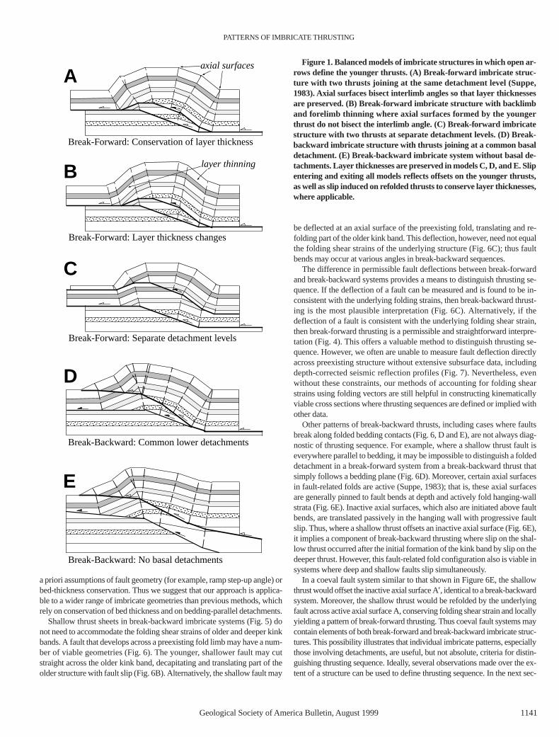
Imbricate structures form by the stacking of two or more thrust sheets(Fig. 1) and are common in fold-and-thrust belts worldwide (Dahlstrom,1969, 1970; Price, 1981; Boyer and Elliot, 1982; Suppe, 1983; McClay andPrice, 1981). Imbricate structures can develop by “break-forward” propa-gation of thrust sheets (Suppe, 1983), by “break-backward” thrusting, orwith generally coeval motion along deep and shallow faults (Boyer, 1992).We use balanced kinematic models to describe characteristic fold patternsthat are used to identify imbricate structures and to distinguish among thesethrusting sequences. We employ area-balance and strain-compatibility con-straints, which are not limited by bed-thickness conservation, to constructkinematically viable interpretations of seismic reflection profiles and crosssections that reflect proper thrusting sequence. We also compare map pat-terns of three-dimensional models with surface images to identify imbricatesystems and infer thrusting sequences.
IMBRICATE PATTERNS IN CROSS SECTION
Imbricate structures have complex shapes in cross section that reflect faultgeometries, detachment levels, folding mechanisms, and thrusting sequence(Fig. 1). Suppe (1983) described the kinematic development of an imbricatefault-bend folding model in which both the shallow thrust fault and overly-
ing anticline are folded above a ramp in a deeper, forward-breaking fault(Fig. 2). Parts of the older thrust sheet are refolded in kink bands generatedby the deeper thrust. Thus, break-forward thrust imbrication yields foldlimbs with multiple dip domains that are bounded by axial surfaces. Suppe(1983) and Mount (1989) provided equations and tabular solutions for im-bricated fold-limb dips that are generated above thrust ramps stepping upfrom detachments. In these solutions, bed length and thickness are preserved.
We describe a new method to construct balanced interpretations for awider range of imbricate structures, including cases without detachmentsand/or where bed thickness is not preserved. Our method accounts for fold-ing shear strains—a measure of deformation caused by each thrust sheet—to predict amounts of refolding in break-forward sequences. Folding shearstrains also provide a means to define thrusting sequence.
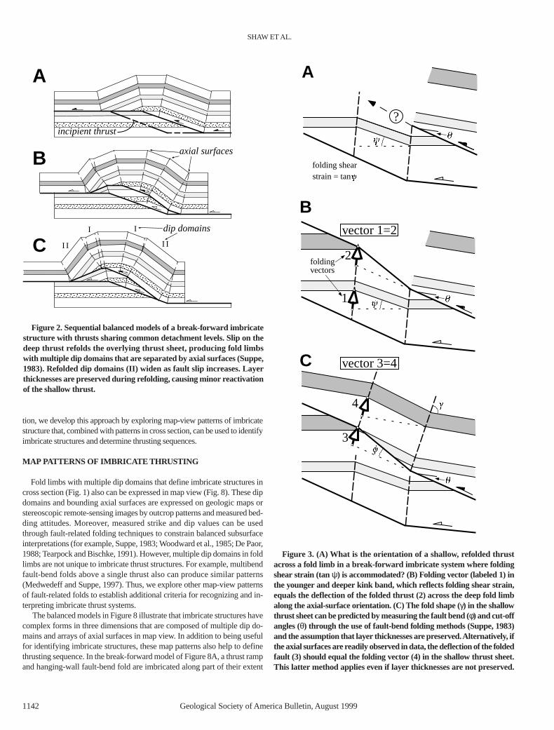
Folding shear strain is an angular measure of the change in orientationof beds and faults across a fold limb or kink band. To account for foldingshear strains, we measure folding vectors that correspond to the deflectionof bedding and faults across a kink band parallel to the bounding axial sur-face(s) (Fig. 3). In a break-forward sequence, the folding shear strain ofbeds in the younger kink band must be accommodated by refolding of theolder, overlying thrust sheet to conserve area during deformation. Thus, thefolding vector of bedding in the deep kink band must equal the amount ofdeflection in the overlying, folded thrust (Fig. 3B). The folding strain also isaccommodated in refolded beds above the shallow thrust if cross-sectionalarea is conserved. Commonly, the axial-surface orientation changes abovethe shallow thrust, perhaps preserving layer thickness. Thus, the foldingvector of the shallow fault measured along the new axial-surface orientationmust equal the deflection of refolded beds in its hanging wall (Fig. 3C).
The technique of accounting for folding shear strains and folding vectorsin break-forward imbricate structures is applicable to both detachment andnondetachment systems, as well as to systems containing more than twofaults. This method relies on a geometric approximation of folding in thrustsheets as simple shear parallel to axial surfaces. The method can account forlateral changes in shear magnitude that may produce angular or curved foldhinges (Suppe et al., 1997). Nevertheless, the applicability of this techniquewill depend on the interpreter’s ability to separate imbricate structures intodip domains or kink bands that share common shear (axial-surface) orien-tations (Mount et al., 1990; Tearpock and Bischke, 1991; Shaw et al., 1994).If axial surfaces generally bisect interlimb angles, then bed length and thick-ness are conserved (Suppe, 1983). Alternatively, axial surfaces may have arange of orientations that do not bisect interlimb angles where bed thicknessis not conserved.
In practice, we suggest that axial-surface orientations are more readilydefined from surface exposures and on seismic reflection data than are faultshapes or minor bed-thickness variations. Our method uses these easily de-fined axial surfaces to interpret imbricate structures (Fig. 4), while avoiding
1140
Patterns of imbricate thrusting
John H. Shaw* Department of Earth and Planetary Sciences, Harvard University, Cambridge, Massachusetts 02138
Frank Bilotti Texaco Exploration and Production Technology Department, Houston, Texas 77042
Peter A. Brennan Consultant, 5003 Plantation Colony Court, Sugar Land, Texas 77478
GSA Bulletin; August 1999; v. 111; no. 8; p. 1140–1154; 14 figures.
*E-mail: [email protected].
PATTERNS OF IMBRICATE THRUSTING
Geological Society of America Bulletin, August 1999 1141
a priori assumptions of fault geometry (for example, ramp step-up angle) orbed-thickness conservation. Thus we suggest that our approach is applica-ble to a wider range of imbricate geometries than previous methods, whichrely on conservation of bed thickness and on bedding-parallel detachments.
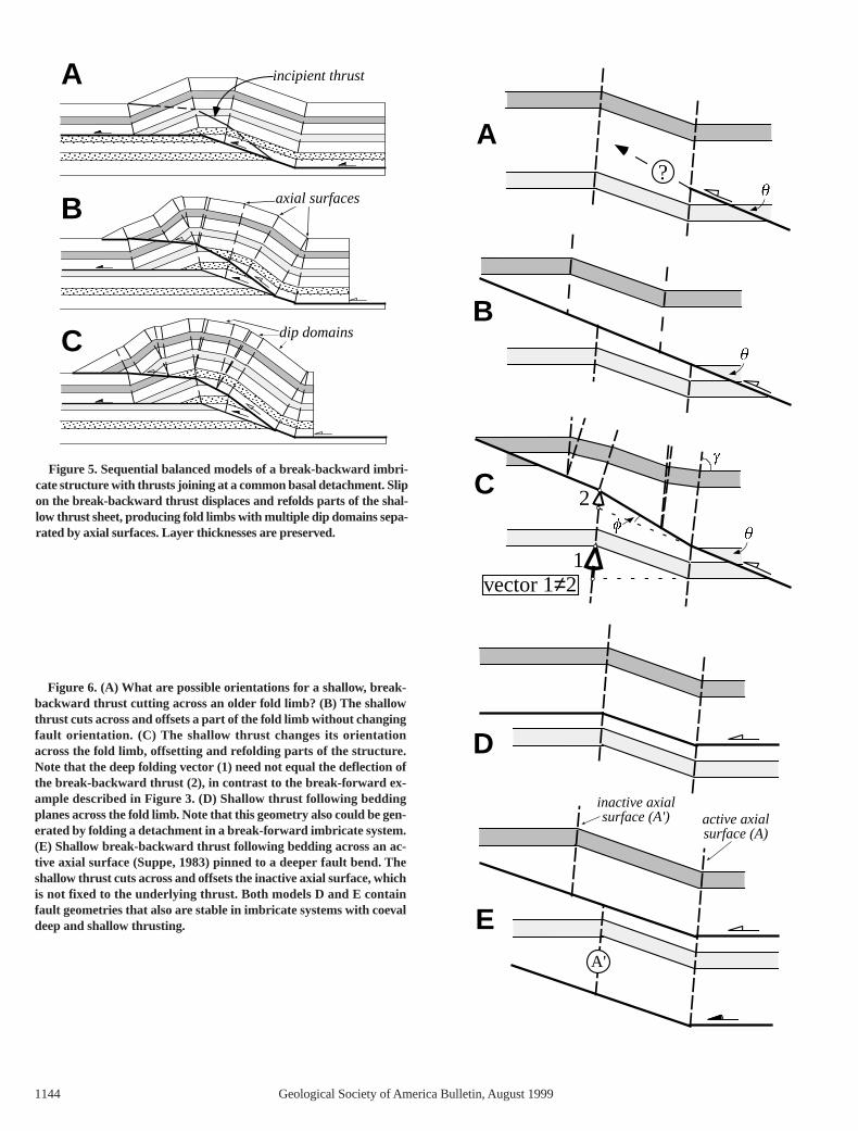
Shallow thrust sheets in break-backward imbricate systems (Fig. 5) donot need to accommodate the folding shear strains of older and deeper kinkbands. A fault that develops across a preexisting fold limb may have a num-ber of viable geometries (Fig. 6). The younger, shallower fault may cutstraight across the older kink band, decapitating and translating part of theolder structure with fault slip (Fig. 6B). Alternatively, the shallow fault may
be deflected at an axial surface of the preexisting fold, translating and re-folding part of the older kink band. This deflection, however, need not equalthe folding shear strains of the underlying structure (Fig. 6C); thus faultbends may occur at various angles in break-backward sequences.
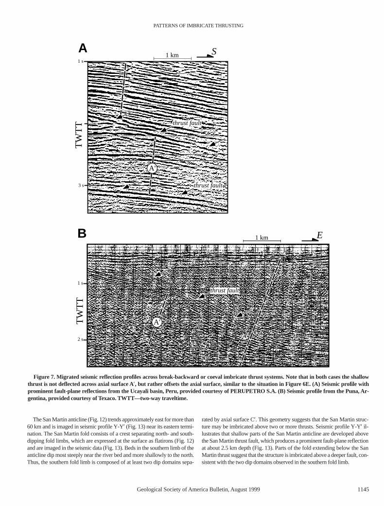
The difference in permissible fault deflections between break-forwardand break-backward systems provides a means to distinguish thrusting se-quence. If the deflection of a fault can be measured and is found to be in-consistent with the underlying folding strains, then break-backward thrust-ing is the most plausible interpretation (Fig. 6C). Alternatively, if thedeflection of a fault is consistent with the underlying folding shear strain,then break-forward thrusting is a permissible and straightforward interpre-tation (Fig. 4). This offers a valuable method to distinguish thrusting se-quence. However, we often are unable to measure fault deflection directlyacross preexisting structure without extensive subsurface data, includingdepth-corrected seismic reflection profiles (Fig. 7). Nevertheless, evenwithout these constraints, our methods of accounting for folding shearstrains using folding vectors are still helpful in constructing kinematicallyviable cross sections where thrusting sequences are defined or implied withother data.
Other patterns of break-backward thrusts, including cases where faultsbreak along folded bedding contacts (Fig. 6, D and E), are not always diag-nostic of thrusting sequence. For example, where a shallow thrust fault iseverywhere parallel to bedding, it may be impossible to distinguish a foldeddetachment in a break-forward system from a break-backward thrust thatsimply follows a bedding plane (Fig. 6D). Moreover, certain axial surfacesin fault-related folds are active (Suppe, 1983); that is, these axial surfacesare generally pinned to fault bends at depth and actively fold hanging-wallstrata (Fig. 6E). Inactive axial surfaces, which also are initiated above faultbends, are translated passively in the hanging wall with progressive faultslip. Thus, where a shallow thrust offsets an inactive axial surface (Fig. 6E),it implies a component of break-backward thrusting where slip on the shal-low thrust occurred after the initial formation of the kink band by slip on thedeeper thrust. However, this fault-related fold configuration also is viable insystems where deep and shallow faults slip simultaneously.
In a coeval fault system similar to that shown in Figure 6E, the shallowthrust would offset the inactive axial surface A′, identical to a break-backwardsystem. Moreover, the shallow thrust would be refolded by the underlyingfault across active axial surface A, conserving folding shear strain and locallyyielding a pattern of break-forward thrusting. Thus coeval fault systems maycontain elements of both break-forward and break-backward imbricate struc-tures. This possibility illustrates that individual imbricate patterns, especiallythose involving detachments, are useful, but not absolute, criteria for distin-guishing thrusting sequence. Ideally, several observations made over the ex-tent of a structure can be used to define thrusting sequence. In the next sec-
D
A
C
B
E
Break-Forward: Conservation of layer thickness
Break-Forward: Layer thickness changes
Break-Backward: Common lower detachments
Break-Backward: No basal detachments
Break-Forward: Separate detachment levels
axial surfaces
layer thinning
Figure 1. Balanced models of imbricate structures in which open ar-rows define the younger thrusts. (A) Break-forward imbricate struc-ture with two thrusts joining at the same detachment level (Suppe,1983). Axial surfaces bisect interlimb angles so that layer thicknessesare preserved. (B) Break-forward imbricate structure with backlimband forelimb thinning where axial surfaces formed by the youngerthrust do not bisect the interlimb angle. (C) Break-forward imbricatestructure with two thrusts at separate detachment levels. (D) Break-backward imbricate structure with thrusts joining at a common basaldetachment. (E) Break-backward imbricate system without basal de-tachments. Layer thicknesses are preserved in models C, D, and E. Slipentering and exiting all models reflects offsets on the younger thrusts,as well as slip induced on refolded thrusts to conserve layer thicknesses,where applicable.
SHAW ET AL.
1142 Geological Society of America Bulletin, August 1999
tion, we develop this approach by exploring map-view patterns of imbricatestructure that, combined with patterns in cross section, can be used to identifyimbricate structures and determine thrusting sequences.
MAP PATTERNS OF IMBRICATE THRUSTING
Fold limbs with multiple dip domains that define imbricate structures incross section (Fig. 1) also can be expressed in map view (Fig. 8). These dipdomains and bounding axial surfaces are expressed on geologic maps orstereoscopic remote-sensing images by outcrop patterns and measured bed-ding attitudes. Moreover, measured strike and dip values can be usedthrough fault-related folding techniques to constrain balanced subsurfaceinterpretations (for example, Suppe, 1983; Woodward et al., 1985; De Paor,1988; Tearpock and Bischke, 1991). However, multiple dip domains in foldlimbs are not unique to imbricate thrust structures. For example, multibendfault-bend folds above a single thrust also can produce similar patterns(Medwedeff and Suppe, 1997). Thus, we explore other map-view patternsof fault-related folds to establish additional criteria for recognizing and in-terpreting imbricate thrust systems.
The balanced models in Figure 8 illustrate that imbricate structures havecomplex forms in three dimensions that are composed of multiple dip do-mains and arrays of axial surfaces in map view. In addition to being usefulfor identifying imbricate structures, these map patterns also help to definethrusting sequence. In the break-forward model of Figure 8A, a thrust rampand hanging-wall fault-bend fold are imbricated along part of their extent
4
3
C
B
2
1
A
?
foldingvectors
vector 1=2
vector 3=4
folding shearstrain = tan
Figure 3. (A) What is the orientation of a shallow, refolded thrustacross a fold limb in a break-forward imbricate system where foldingshear strain (tan ψ) is accommodated? (B) Folding vector (labeled 1) inthe younger and deeper kink band, which reflects folding shear strain,equals the deflection of the folded thrust (2) across the deep fold limbalong the axial-surface orientation. (C) The fold shape (γ) in the shallowthrust sheet can be predicted by measuring the fault bend (φ) and cut-offangles (θ) through the use of fault-bend folding methods (Suppe, 1983)and the assumption that layer thicknesses are preserved. Alternatively, ifthe axial surfaces are readily observed in data, the deflection of the foldedfault (3) should equal the folding vector (4) in the shallow thrust sheet.This latter method applies even if layer thicknesses are not preserved.
I dip domains
I I
incipient thrust
I
I I
A
B
C
axial surfaces
Figure 2. Sequential balanced models of a break-forward imbricatestructure with thrusts sharing common detachment levels. Slip on thedeep thrust refolds the overlying thrust sheet, producing fold limbswith multiple dip domains that are separated by axial surfaces (Suppe,1983). Refolded dip domains (II) widen as fault slip increases. Layerthicknesses are preserved during refolding, causing minor reactivationof the shallow thrust.

PATTERNS OF IMBRICATE THRUSTING
Geological Society of America Bulletin, August 1999 1143
by a deeper thrust. Slip on the break-forward thrust (fault Y) begins betweensections 1 and 2 and increases toward section 3. This slip refolds the shallowthrust sheet above fault X, producing multiple dip domains in fold limbs andadditional structural relief. In map view, erosion exposes older rocks in thecore of the fold (Fig. 8B). Moreover, bed contacts and axial surfaces in theshallow thrust sheet are deflected by varying amounts in the transport di-rection of the deep thrust. The bed contacts and anticlinal axial surfaces nearthe fold crest and in the forelimb are deflected most significantly. Thus,break-forward imbricate structures often have patterns of deflected axialsurfaces and bed contacts that are coincident with areas of greater structuralrelief (Fig. 9).
In contrast to the break-forward model, the anticlinal fold axes are nottranslated significantly by the break-backward thrust in Figure 8C because
they are linked to static elements of the subthrust structure. However, instructures where break-backward thrusts simply decapitate older structures(for example, Fig. 6B), axial surfaces may be deflected by shallow faulting,producing patterns that are somewhat similar to break-forward structures.Thus, given the wide range of possible imbricate geometries, map-view pat-terns of individual structures are not always fully diagnostic of thrusting se-quence. However, in cases where two or more fold trends overlap along thetransport direction in map view, unique fold patterns can result that help todistinguish thrusting sequences (Fig. 10).
In break-forward thrust systems, older hinterland structures are trans-ported in the hanging walls of younger and deeper thrusts. Where slip onthese younger faults varies along strike, hinterland structures commonly aredeflected in the direction of thrust displacement (Fig. 10) (Snedden andSpang, 1989; Tearpock and Bischke, 1991). Thrusts may also be deflectedin coeval fault systems or show apparent deflection due to curved faultsformed as thrusts propagate toward one another, similar to common patternsof joint systems (Pollard and Aydin, 1988). In contrast, older structures inbreak-backward sequences do not undergo translation by deeper faults andthus are not deflected in the transport direction. Patterns of overlapping foldtrends in map view, therefore, can be used to help distinguish break-forwardand coeval fault systems from break-backward imbricates (Fig. 11).
AN EXAMPLE OF COMPLEX IMBRICATE THRUSTING FROMTHE PERUVIAN ANDES
We conclude our discussion by presenting an analysis of several largefold trends in the Peruvian Andes that exhibit complex patterns of imbri-cate thrusting. The anticlinal structures (San Martin and Istmo) lie in theAndean foothills of the southern Ucayali basin (Fig. 12) and involvethrust sheets of Paleozoic through Tertiary strata (Bellido B., 1969;Mathalone and Montoya R., 1995; Geuns, 1997). Although covered bydense vegetation, the folds are directly expressed in multispectral satel-lite images (Fig. 12). We use these images to describe basic fold patternsas well as to derive surface bedding-attitude measurements from stereo-scopic LandsatTM and SPOT imagery (Berger, 1992; Shaw et al., 1997).The stereoscopically derived measurements are combined with high-quality seismic reflection profiles (Fig. 13) to define the imbricategeometries and thrusting sequence. Notably, the surface measurementsare very consistent with shallow dips imaged on depth-converted seismicreflection data (Figs. 12 and 13).
Figure 4. Migrated and depth-converted seismic reflection profileacross a faulted anticline from the southern Ucayali basin, Peru. (A) Thrust fault defined by fault-plane reflection at about 2.5 km depthbeneath the forelimb (left). Note that axial surface A′ extends below theobserved thrust, indicating that a second, deeper fault underlies thestructure. Axial surface A′ is not deflected or offset, suggesting that theshallow thrust is folded in a break-forward imbricate system. (B) Methodof generating a balanced interpretation of the shallow thrust geometry ina break-forward imbricate structure. On the basis of the forelimb cut-off(β) and interlimb angle (γ) about axial surface B, the fault-bend foldingtheory (Suppe, 1983) predicts that the fault dip changes by 9° to a 22°Sdip across axial surface B. Folding of this 22°S-dipping thrust segmentacross axial surface A′ by using the method of Figure 3 yields a backlimbramp dip of about 28°S, which is roughly equal to bed dips in the re-folded panel (II). The inverse folding vector (1) in the deep kink bandequals the deflection of the shallow thrust (2) along the orientation of ax-ial surface A′. Axial-surface nomenclature after Shaw et al. (1994). Seis-mic data provided courtesy of PERUPETRO S.A.
1144 Geological Society of America Bulletin, August 1999
incipient thrustA
B
C
axial surfaces
dip domains
Figure 5. Sequential balanced models of a break-backward imbri-cate structure with thrusts joining at a common basal detachment. Slipon the break-backward thrust displaces and refolds parts of the shal-low thrust sheet, producing fold limbs with multiple dip domains sepa-rated by axial surfaces. Layer thicknesses are preserved.
?
A
B
C 2
1vector 1≠2
D
E
active axialsurface (A)
inactive axialsurface (A')
A'
Figure 6. (A) What are possible orientations for a shallow, break-backward thrust cutting across an older fold limb? (B) The shallowthrust cuts across and offsets a part of the fold limb without changingfault orientation. (C) The shallow thrust changes its orientationacross the fold limb, offsetting and refolding parts of the structure.Note that the deep folding vector (1) need not equal the deflection ofthe break-backward thrust (2), in contrast to the break-forward ex-ample described in Figure 3. (D) Shallow thrust following beddingplanes across the fold limb. Note that this geometry also could be gen-erated by folding a detachment in a break-forward imbricate system. (E) Shallow break-backward thrust following bedding across an ac-tive axial surface (Suppe, 1983) pinned to a deeper fault bend. Theshallow thrust cuts across and offsets the inactive axial surface, whichis not fixed to the underlying thrust. Both models D and E containfault geometries that also are stable in imbricate systems with coevaldeep and shallow thrusting.
PATTERNS OF IMBRICATE THRUSTING
Geological Society of America Bulletin, August 1999 1145
The San Martin anticline (Fig. 12) trends approximately east for more than60 km and is imaged in seismic profile Y-Y′ (Fig. 13) near its eastern termi-nation. The San Martin fold consists of a crest separating north- and south-dipping fold limbs, which are expressed at the surface as flatirons (Fig. 12)and are imaged in the seismic data (Fig. 13). Beds in the southern limb of theanticline dip most steeply near the river bed and more shallowly to the north.Thus, the southern fold limb is composed of at least two dip domains sepa-
rated by axial surface C′. This geometry suggests that the San Martin struc-ture may be imbricated above two or more thrusts. Seismic profile Y-Y′ il-lustrates that shallow parts of the San Martin anticline are developed abovethe San Martin thrust fault, which produces a prominent fault-plane reflectionat about 2.5 km depth (Fig. 13). Parts of the fold extending below the SanMartin thrust suggest that the structure is imbricated above a deeper fault, con-sistent with the two dip domains observed in the southern fold limb.
1 s
3 s
A
TW
TT
S1 km
thrust fault
thrust fault
A'
1 km
1 s
2 s
TW
TT
EB
A'
thrust fault
Figure 7. Migrated seismic reflection profiles across break-backward or coeval imbricate thrust systems. Note that in both cases the shallowthrust is not deflected across axial surface A′, but rather offsets the axial surface, similar to the situation in Figure 6E. (A) Seismic profile withprominent fault-plane reflections from the Ucayali basin, Peru, provided courtesy of PERUPETRO S.A. (B) Seismic profile from the Puna, Ar-gentina, provided courtesy of Texaco. TWTT—two-way traveltime.

1146 Geological Society of America Bulletin, August 1999
1
2
3
fault X
A
fault Y
fault X
slip
on
faul
t Y
fault Y
C1
2
3
slip
on
faul
t Z
fault X
fault Xfault Z
fault Z
1
2
3
B
fault Y
fault X
slip
on
faul
t Y
D1
2
3
slip
on
faul
t Z
fault Xfault Z
Break-Forward Sequence
Break-backward sequence
Figure 8. Perspective views of three-dimensional imbricate structures. (A) Break-forward imbricate structure with two faults (X and Y) thatshare common upper and lower detachments. Slip on break-forward thrust Y begins between sections 1 and 2 and increases toward section 3.(B) View of break-forward imbricate structure at a horizontal erosion level. Note the prominent map-view deflection of axial surfaces and bed-ding contacts caused by motion on the break-forward thrust Y. (C) Break-backward imbricate structure with two faults (X and Z) sharing acommon basal detachment. Slip on break-backward thrust Z begins between sections 1 and 2 and increases toward section 3. (D) View of break-backward imbricate structure at a horizontal erosion level. Although anticlinal axial surfaces are not obviously deflected in the break-backwardmodel, the break-backward and break-forward models share many other characteristics. These include multiple map-view dip domains anddeflected bed contacts that are coincident with exposures of older strata in the fold cores.

PATTERNS OF IMBRICATE THRUSTING
Geological Society of America Bulletin, August 1999 1147
The Istmo anticline lies northeast of the San Martin structure (Fig. 12)and is developed above a second fault, the Istmo thrust, which also is im-aged by a fault-plane reflection (Fig. 13). Along section Y-Y′, the south-dipping Istmo thrust extends beneath the San Martin anticline. Our projec-tion of the Istmo thrust beneath the San Martin anticline, guided byfault-bend fold theory (Suppe, 1983), is consistent with the shape of the sub-thrust fold. Thus, we suggest that slip on the Istmo thrust generated this deepfold and imbricated the overlying San Martin thrust sheet.
The part of the San Martin structure that is imbricated by the Istmo thrustcorresponds to the overlap of the two fold trends in map view (Fig. 12).West of the imbricated zone, the southern limb of the San Martin thrust dipsuniformly between 8° and 12°S. The steeper, refolded kink band (20°–30°dip) is not present and therefore did not generate the prominent flatironspresent in the imbricated zone. Thus, the map-view pattern of the southernlimb of the San Martin trend, including axial surface C′ (Fig. 12), clearly de-fines the extent of thrust imbrication, which is corroborated by the seismicreflection data (Fig. 13). Notably, this imbricated zone coincides with astructurally high area of the San Martin fold because slip on both the SanMartin and Istmo thrusts contributed to its uplift and structural relief.
Seismic profile Y-Y′ also provides insight into the thrusting sequence ofthe San Martin and Istmo faults. The deflection of the San Martin thrust onthe south side of the San Martin anticline is consistent with the folding shear
strain of the underlying kink band, as described previously with respect toFigure 4. We interpret the deep kink band to be generated above the Istmothrust (Fig. 13). Thus, the shape of the San Martin fault is compatible withits having been refolded above the Istmo thrust in a break-forward or coevalthrust system. In contrast, the north limb of the San Martin anticline im-pinges on the back limb of the Istmo fold, but is not refolded by the deeperkink band (Fig. 12). If the Istmo fault had slipped after the San Martinthrust, then the forelimb of the San Martin structure should be folded abovethe Istmo structure, which it is not. The forelimb pattern indicates, therefore,that some of the slip on the San Martin thrust occurred after motion ceasedon the Istmo fault, which is consistent with a break-backward fault system.Thus, the seismic section provides conflicting evidence about the thrustingsequence. To help resolve this ambiguity, we next explore map-view pat-terns of these imbricate structures.
The area where the San Martin structure is imbricated by the Istmo thrustcorresponds to the zone of overlap between the anticlinal trends, as reflectedin the satellite imagery (Fig. 12). In this zone, the anticlinal axis of the SanMartin anticline is deflected to the north as the width, structural relief, andslip on the Istmo trend increase to the east. This anticlinal deflection is sim-ilar to the break-forward and coeval imbricate fold patterns depicted in Fig-ures 8B and 10 and contrasts with the break-backward map-view patternsof Figure 8D. Thus, the map-view pattern is consistent with the refolding of
33
22
11
Nff ooll ddaaxx eess
2 km
31°25'
68°25'
transport direction
map-viewimbricate model
Figure 9. Landsat thematic mapper image of an anticlinal trend in the Katawaz basin, Pakistan. Deflection of the anticlinal fold axis from sec-tion 1 to section 3 corresponds with exposure of older strata in the fold core, analogous to patterns of break-forward imbricate thrusting in Fig-ure 8B. Section traces are provided as a reference frame for comparison between the image and imbricate models (Fig. 8).

1148 Geological Society of America Bulletin, August 1999
1
2
3
B
fault X
fault Y
slip
on
faul
t X4
slip
on
faul
t Y
fault X and overlying anticlinedeflected in transport direction
of fault Y
1
2
3
A
fault X
fault Y
slip
on
faul
t X4
slip
on
faul
t Y
Figure 10. Perspective views of en echelon fault-bend folds developed above break-forward or coeval thrusts. (A) A fault-bend fold is developedabove a ramp in fault X, on which slip decreases in both directions along strike (open arrows). Slip on frontal thrust Y begins between sections 2and 3 and increases toward section 4. (B) View of the en echelon folds at a horizontal erosion level. Slip on fault Y transports fault X and its over-lying structure, causing a map-view deflection of the fault-bend fold above ramp X in the transport direction of thrust Y. Asymmetry betweenthe plunging noses of the fold above fault X contrasts with symmetric models of doubly plunging fault-related folds that are not affected by break-forward thrusting (Wilkerson et al., 1991).

PATTERNS OF IMBRICATE THRUSTING
Geological Society of America Bulletin, August 1999 1149
the San Martin thrust on the south limb of the San Martin anticline, both ofwhich suggest break-forward or coeval thrust motion. Recall, however, thatthese indications are in contrast with the truncation of the southern limb ofthe Istmo anticline by the San Martin thrust in cross section (Fig. 13), whichsuggests a component of break-backward thrusting.
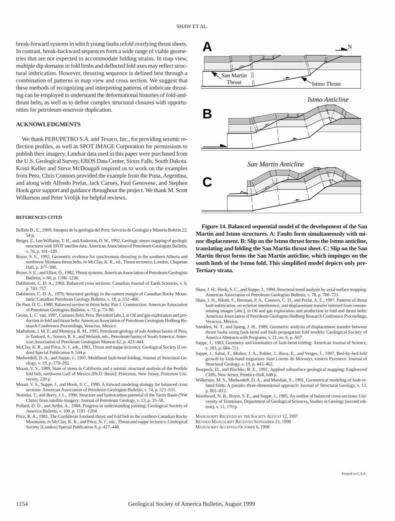
We propose that these conflicting fold and fault patterns result from a com-plex slip history on the San Martin and Istmo faults (Fig. 14). If the faultsformed simultaneously, but the majority of early slip occurred on the Istmothrust, this would cause refolding in cross section (Fig. 4) and map-view de-flection (Fig. 12) of the San Martin thrust as observed. After motion on theIstmo thrust ceased, slip on the San Martin thrust (Fig. 14C) would truncatethe southern limb of the Istmo anticline as imaged in the seismic profile(Fig. 13). Thus generally coeval, but episodic fault motions can produce all ofthe local imbricate patterns, which considered individually would yield con-flicting results. This statement illustrates that recognition of several fold andfault patterns, dispersed across the structure in cross section and map view, isthe most powerful approach to defining the sequence of imbricate thrusting.
SUMMARY AND CONCLUSIONS
Methods of identifying imbricate systems and defining thrusting se-quence have important applications. The number, amount of slip, and rela-tive timing of thrust faults must be determined to assess properly the mag-nitudes and rates of crustal shortening in fold-and-thrust belts. Intectonically active areas, imbricate structures may contain several faults thatcan cause damaging earthquakes. Thus, recognition and proper definitionof these structures can be important for hazards assessment. Moreover, im-bricate structures commonly form fold and fault closures with repetition ofreservoir strata to yield large hydrocarbon traps. Thrusting sequence alsocan influence the thermal maturation of hydrocarbons and charge pathwaysfor these traps, such that proper definition of imbricate structures is impor-tant for hydrocarbon exploration. Thus, we defined patterns in cross sectionand map view that help to identify imbricate structures and define thrustingsequences.
Measures of folding shear strain in cross section help to distinguish
5 km
transportdirection
deflection of fold axestoward vergence direction
41°15' 81°00'
5 km
Figure 11. Landsat thematic mapper image of en echelon anticlines from the northwestern Tarim basin, China. Note the asymmetry of the an-ticlines, with deflection of the fold axes in the transport direction of the structures where folds overlap. This pattern is interpreted to reflect a com-ponent of break-forward thrusting, similar to the models in Figure 11. The fold asymmetry is not diagnostic of structural vergence or transportdirection, which is inferred from seismic data published and interpreted by Nishidai and Berry (1990).

1150 Geological Society of America Bulletin, August 1999
Figure 12. SPOT multispectral image of the San Martin, Istmo, and Cashiriari imbricate structures in the southern Ucayali basin, Peru. Sur-face attitude measurements are obtained from bedding contacts in flatirons by using stereoscopic SPOT and Landsat thematic mapper imagery.Stereoscopically derived strikes and dips generally are consistent with attitudes from shallow reflections on seismic depth profiles and are used tointerpret fold patterns indicative of the imbricate thrusting and faulting sequence. The zone of en echelon overlap between the Istmo and SanMartin folds corresponds to the region where the San Martin thrust is imbricated above the Istmo fault. Imbrication is expressed by multiple dip

Geological Society of America Bulletin, August 1999 1151
Figure 12 (Continued). domains that are separated by axial surface C′ on the south limb of the San Martin anticline, as well as map-view de-flection of the San Martin trend toward the northward transport direction of the Istmo thrust. Line Y–Y ′ is the location of the migrated seismicdepth profile in Figure 13. Attitude measurements from seismic depth profiles are apparent values corrected to true strike and dip where obvioussurface contacts provide bed strike. Image © CNES/SPOT Image.

1152 Geological Society of America Bulletin, August 1999
Figure 13. Time-migrated seismic reflection profile Y–Y′ converted to depth across the Cashiriari, San Martin, and Istmo structures. (A) Un-interpreted section showing prominent fault-plane reflections of the San Martin and Istmo thrusts. Note the consistency between surface dipsderived from the stereoscopic remote-sensing imagery and shallow reflections. (B) Interpreted profile. Multiple dip domains in the southernlimb of the San Martin anticline separated by axial surface C′ are consistent with imbrication of the structure above the San Martin and Istmothrusts. Note the upward termination of the syncline at the San Martin thrust on the south limb of the Istmo trend, indicating a component ofbreak-backward faulting (see text for discussion). Seismic data provided courtesy of PERUPETRO S.A.

Geological Society of America Bulletin, August 1999 1153
Figure 13. (Continued).
SHAW ET AL.
1154 Geological Society of America Bulletin, August 1999
break-forward systems in which young faults refold overlying thrust sheets.In contrast, break-backward sequences form a wide range of viable geome-tries that are not expected to accommodate folding strains. In map view,multiple dip domains in fold limbs and deflected fold axes may reflect struc-tural imbrication. However, thrusting sequence is defined best through acombination of patterns in map view and cross section. We suggest thatthese methods of recognizing and interpreting patterns of imbricate thrust-ing can be employed to understand the deformational histories of fold-and-thrust belts, as well as to define complex structural closures with opportu-nities for petroleum-reservoir duplication.
ACKNOWLEDGMENTS
We thank PERUPETRO S.A. and Texaco, Inc., for providing seismic re-flection profiles, as well as SPOT IMAGE Corporation for permissions topublish their imagery. Landsat data used in this paper were purchased fromthe U.S. Geological Survey, EROS Data Center, Sioux Falls, South Dakota.Kristi Keller and Steve McDougall inspired us to work on the examplesfrom Peru. Chris Connors provided the example from the Puna, Argentina,and along with Alfredo Prelat, Jack Carnes, Paul Genovese, and StephenHook gave support and guidance throughout the project. We thank M. ScottWilkerson and Peter Vrolijk for helpful reviews.
REFERENCES CITED
Bellido B., E., 1969, Sinopsis de la geología del Perú: Servicio de Geología y Minería Boletín 22,54 p.
Berger, Z., Lee Williams, T. H., and Anderson, D. W., 1992, Geologic stereo mapping of geologicstructures with SPOT satellite data:American Association of Petroleum Geologists Bulletin,v. 76, p. 101–120.
Boyer, S. E., 1992, Geometric evidence for synchronous thrusting in the southern Alberta andnorthwest Montana thrust belts,in McClay, K. R., ed., Thrust tectonics: London, ChapmanHall, p. 377–390.
Boyer, S. E., and Elliot, D., 1982, Thrust systems:American Association of Petroleum GeologistsBulletin, v. 66, p. 1196–1230.
Dahlstrom, C. D. A., 1969, Balanced cross sections: Canadian Journal of Earth Sciences, v. 6,p. 743–757.
Dahlstrom, C. D. A., 1970, Structural geology in the eastern margin of Canadian Rocky Moun-tains: Canadian Petroleum Geology Bulletin, v. 18, p. 332–406.
De Paor, D. G., 1988, Balanced section in thrust belts: Part 1. Construction:American Associationof Petroleum Geologists Bulletin, v. 72, p. 73–90.
Geuns, L. C. van, 1997, Camisea field, Peru: Revisited [abs.],in Oil and gas exploration and pro-duction in fold and thrust belts:American Association of Petroleum Geologists Hedberg Re-search Conference Proceedings, Veracruz, Mexico.
Mathalone, J. M. P., and Montoya, R. M., 1995, Petroleum geology of sub-Andean basins of Peru,in Tankard,A., Soruco, R. S., and Welsink, eds., Petroleum basins of South America:Amer-ican Association of Petroleum Geologists Memoir 62, p. 423–444.
McClay, K. R., and Price, N. J., eds., 1981, Thrust and nappe tectonics: Geological Society [Lon-don] Special Publication 9, 544 p.
Medwedeff, D. A., and Suppe, J., 1997, Multibend fault-bend folding: Journal of Structural Ge-ology, v. 19, p. 279–292.
Mount, V. S., 1989, State of stress in California and a seismic structural analysis of the Perdidofold belt, northwest Gulf of Mexico [Ph.D. thesis]: Princeton, New Jersey, Princeton Uni-versity, 220 p.
Mount, V. S., Suppe, J., and Hook, S. C., 1990, A forward modeling strategy for balanced crosssections: American Association of Petroleum Geologists Bulletin, v. 74, p. 521–531.
Nishidai, T., and Berry, J. L., 1990, Structure and hydrocarbon potential of the Tarim Basin (NWChina) from satellite imagery: Journal of Petroleum Geology, v. 13, p. 35–58.
Pollard, D. D., and Aydin, A., 1988, Progress in understanding jointing: Geological Society ofAmerica Bulletin, v. 100, p. 1181–1204.
Price, R. A., 1981, The Cordilleran foreland thrust and fold belt in the southern Canadian RockyMountains,in McClay, K. R., and Price, N. J., eds., Thrust and nappe tectonics: GeologicalSociety [London] Special Publication 9, p. 427–448.
Shaw, J. H., Hook, S. C., and Suppe, J., 1994, Structural trend analysis by axial surface mapping:American Association of Petroleum Geologists Bulletin, v. 78, p. 700–721.
Shaw, J. H., Bilotti, F., Brennan, P. A., Connors, C. D., and Prelat, A. E., 1997, Patterns of thrustfault imbrication, en-echelon interference, and displacement transfer inferred from remote-sensing images [abs.],in Oil and gas exploration and production in fold and thrust belts:American Association of Petroleum Geologists Hedberg Research Conference Proceedings,Veracruz, Mexico.
Snedden, W. T., and Spang, J. H., 1989, Geometric analysis of displacement transfer betweenthrust faults using fault-bend and fault-propagation fold models: Geological Society ofAmerica Abstracts with Programs, v. 21, no. 6, p. A67.
Suppe, J., 1983, Geometry and kinematics of fault-bend folding: American Journal of Science,v. 283, p. 684–721.
Suppe, J., Sabat, F., Muñoz, J. A., Poblet, J., Roca, E., and Verges, J., 1997, Bed-by-bed foldgrowth by kink-band migration: Sant Lorenc de Morunys, eastern Pyrenees: Journal ofStructural Geology, v. 19, p. 443–462.
Tearpock, D., and Bischke, R. E., 1991, Applied subsurface geological mapping: EnglewoodCliffs, New Jersey, Prentice-Hall, 648 p.
Wilkerson, M. S., Medwedeff, D. A., and Marshak, S., 1991, Geometrical modeling of fault-re-lated folds: A pseudo–three-dimensional approach: Journal of Structural Geology, v. 13,p. 801–812.
Woodward, N. B., Boyer, S. E., and Suppe, J., 1985, An outline of balanced cross-sections: Uni-versity of Tennessee, Department of Geological Sciences, Studies in Geology (second edi-tion), v. 11, 170 p.
MANUSCRIPTRECEIVED BY THESOCIETYAUGUST12, 1997REVISEDMANUSCRIPTRECEIVEDSEPTEMBER21, 1998MANUSCRIPTACCEPTEDOCTOBER6, 1998
San Martin Anticline
Istmo Anticline
Istmo Thrust
San MartinThrust
A
C
B
N
Figure 14. Balanced sequential model of the development of the SanMartin and Istmo structures. A: Faults form simultaneously with mi-nor displacement. B: Slip on the Istmo thrust forms the Istmo anticline,translating and folding the San Martin thrust sheet. C: Slip on the SanMartin thrust forms the San Martin anticline, which impinges on thesouth limb of the Istmo fold. This simplified model depicts only pre-Tertiary strata.
Printed in U.S.A.