patent no.: us 8,551,333 b2 lin et al. · (75) inventors: adam yuh lin, irvine, ca (us); tak sing...
TRANSCRIPT

1111111111111111111inmuuu~
(12) United States Patent Lin et al.
(54) PARTICLE-BASED MICROFLUIDIC DEVICE FOR PROVIDING HIGH MAGNETIC FIELD GRADIENTS
(75) Inventors: Adam Yuh Lin, Irvine, CA (US); Tak Sing Wong, Los Angeles, CA (US)
(73) Assignee: The Regents of the University of California, Oakland, CA (US)
(*) Notice: Subject to any disclaimer, the term of this patent is extended or adjusted under 35 U.S.C. 154(b) by 500 days.
(21) Appl. No.: 12/594,179
(22) PCT Filed: Apr. 7, 2008
(86) PCT No.: PCT/US2008/004483
§ 371 (c)(1), (2), (4) Date: Sep. 30, 2009
(87) PCT Pub. No.: W02009/008925
PCT Pub. Date: Jan. 15, 2009
(65) Prior Publication Data
US 2010/0044232 Al Feb. 25, 2010
Related U.S. Application Data
(60) Provisional application No. 60/907,501, filed on Apr. 5, 2007.
(51) Int. Cl. B03C1102 (2006.01) C12M 1/00 (2006.01)
(52) U.S. Cl. USPC ................... 210/222; 252/62.51 R; 422/68.1;
422/502; 422/504; 422/527; 435/287.2; 435/308.1; 436/526; 436/806
(58) Field of Classification Search USPC ........... 210/222; 252/62.51 R; 422/68.1, 502,
422/504, 527; 435/287.2, 308.1; 436/526, 436/806
See application file for complete search history.
(1o) Patent No.: US 8,551,333 B2 (45) Date of Patent: Oct. 8, 2013
(56) References Cited
U.S. PATENT DOCUMENTS
2004/0018611 Al 1/2004 Ward et al. 2008/0124779 Al * 5/2008 Oh et al . .................... 435/173.9
FOREIGN PATENT DOCUMENTS
WO WO 2009008925 A2 * 1/2009
OTHER PUBLICATIONS
Written Opinion of the International Searching Authority for PCT/
US08/04483, dated Nov. 29, 2008.* Chalmers; et al., "Flow Through, Imrnunomagnetic Cell Separation", Biotechnol. Prog. (1998), 14(1):141-148.
(Continued)
Primary Examiner David A Reifsnyder (74) Attorney, Agent, or Firm Bozicevic, Field & Francis LLP; Pamela J. Sherwood
(57) ABSTRACT
A microfluidic device for manipulating particles in a fluid has a device body that defines a main channel therein, in which the main channel has an inlet and an outlet. The device body further defines a particulate diverting channel therein, the particulate diverting channel being in fluid connection with the main channel between the inlet and the outlet of the main channel and having a particulate outlet. The microfluidic device also has a plurality of microparticles arranged proxi-mate or in the main channel between the inlet of the main channel and the fluid connection of the particulate diverting channel to the main channel. The plurality of microparticles each comprises a material in a composition thereof having a magnetic susceptibility suitable to cause concentration of magnetic field lines of an applied magnetic field while in operation. A microfluidic particle-manipulation system has a microfluidic particle-manipulation device and a magnet dis-posed proximate the microfluidic particle-manipulation device.
12 Claims, 9 Drawing Sheets
I arm ll~,
1 Media Shearing
— — r — Main Separation Channel Waste
Outlet Laminar Sample Flow Inlet Lines
Media
Side Channel A„
¢~ I Magnetic
Outlet
Magnetic Beads O Target Cell or Molecule O Non-target Cell or Molecule o Nickel particles
https://ntrs.nasa.gov/search.jsp?R=20150003121 2019-03-01T18:31:57+00:00Z
US 8,551,333 B2 Page 2
(56) References Cited
OTHER PUBLICATIONS
Chalmers; et al., "Theoretical Analysis of Cell Separation Based on Cell Surface Marker Density", Biotechnology and Bioengineering
(1998), 59(1)10-20. Choi; et al., "Development and Characterization of Microfluidic Devices and Systems for Magnetic Bead-Based Biochemical Detec-tion", Biomedical Microdevices (2001), 3(3):191-200. Dudley, "To Bead or Not to Bead", Journal of Immunotherapy (2003), 26(3):187-189. Gij s, "Magnetic bead handling on-chip: new opportunities for ana-lytical applications", Microfluid Nanofluid (2004), 1:22-40. Han; et al., "Paramagnetic capture mode magnetophoretic microseparator for high efficiency blood cell separations", Lap Chip (2006), 6:265-273. Hoyos; et al., "Study of magnetic particles pulse-injected into an annular SPLITT-like channel inside a quadrupole magnetic field", Journal of Chromatography (2000), 903:99-116. Hu; et al., "Marker-specific sorting of rare cells using dielectrophoresis", PNAS (2005), 102(44):15757-15761. Inglis; et al., "Continuous microfluidic immunomagnetic cell sepa-ration", Applied Physics Letter (2004), 85 (21):5093-95.
Krupke; et al., "Separation of Metallic from Semiconducting Single-Walled Carbon Nanotubes", Science (2003), 301:344-347. Miwa; et al., "Development of micro immunoreaction-based cell sorter for regenerative medicine", The First International Conference on Bio -Nano -Information Fusion, Jul. 20-22, 2005, 4 pages. Ramadan; et al., "An integrated microfluidic platform for magnetic microbeads separation and confinement", Biosensors and Bioelectromes (2006), 21:1693-1702. Ramadan; et al., "Magnetic-based microfluidic platform for biomolecular separation", Biomed Microdevices (2006), 8:151-158. Reddy; et al., "Determination of the Magnetic Susceptibility of Labeled Particles by Video Imaging", Chemical Engineering Science (1996), 51(6):947-956. Sun; et al., "Continuous, Flow-Through Immunomagnetic Cell Sort-ing in a Quadrupole Field", Cytometry (1998), 33:469-475. Suzuki; et al., "A Chaotic Mixer of Magnetic Bead-Based Micro Cell Sorter", Journal of MIcroelectromechanical Systems (2004), 13(5):779-790. Xia; et al., "Combined microfluidic-micromagnetic separation of living cells in continuous flow" Biomed Microdevices (2006), 8:299-308. Zborowski; et al., "Analytical Magnetapheresis of Ferritin-Labeled Lymphocytes", Analytical Chemistry (1995), 67 (20):3702-3712.
* cited by examiner

1 `za
NOW
a~
an w
U.S. Patent Oct. 8, 2013 Sheet 1 of 9 US 8,551,333 B2

Sheari Media
U.S. Patent Oct. 8, 2013 Sheet 2 of 9
US 8,551,333 B2
w s
Shearing Media Main Separation Channel
i Waste
Laminar Sample
Flow Inlet
Lines
Target Outlet
I Magnetic Beads O Target Cell or Molecule
Magnetic Field O Non-target Cell or Molecule o Nickel particles
Figure 1 C

J Channel B
Separation Flow
a Sample Flow
Main Channel
U.S. Patent Oct. 8, 2013 Sheet 3 of 9
US 8,551,333 B2
Figures 2A-2D
...............
Sample Pump Media Pump
Microfluidic Chip
E~ Media Syringe (500ul-)
Media Syringe (250ul-)
Sample Syringe (250ul-)
Magnet Glass Tubing
Figure 3

U.S. Patent Oct. 8, 2013 Sheet 4 of 9 US 8 ,551,333 B2
i
S
^C
Lu
' z ~
~ ys4
„ E 1
W
d'
Q~
r~~
v

Figure 6
U.S. Patent Oct. 8, 2013 Sheet 5 of 9 US 8,551,333 B2
A1 200
400
600
800
500 1000 1500 2000 2500
0 480
490 r~
495
$00
Figures 5A, 5B
X Pixel 40 600 SM 1000 1200 144 16th 1800

U.S. Patent Oct. 8, 2013 Sheet 6 of 9
US 8,551,333 B2
Trial Ni Magnet Cell Image Set
1 8.88E-03 2.03E-03 6.43E-04 2 7.29E-03 3.41 E-03 2.67E-04 3 8.46E-03 3.18E-03 6.54E-05 4 8.31E-03 1.76E-03 2.26E-03 5 8.10E-03 2.54E-03 8.87E-04 6 7.96E-03 3.94E-03 2.27E-03 7 7.71 E-03 3.10E-03 -6.89E-04 8 7.67E-03 2.86E-03 1.58E-04 9 8.01 E-03 3.39E-03 2.33E-03 10 7.94E-03 1.36E-03 6.50E-04 11 7.73E-03 2.60E-03 2.55E-03 12 8.40E-03 3.41 E-03 6.35E-04 13 8.36E-03 3.44E-04 1.99E-03 14 8.19E-03 1.20E-03 7.08E-04 15 8.12E-03 1.47E-03 7.17E-04
Average 8.08E-03 2.44E-03 1.03E-03 Standard Error 1.01 E-04 2.66E-04 2.57E-04
Standard Deviation 3.89E-04 1.03E-03 9.95E-04 Variance 1.52E-07 1.07E-06 9.89E-07
Stand Err/Avg % 1.2 10.9 25.0
Ni - Magnet Magnet - Cell Ni - Cell t-value 19.79 3.81 25.55
Figure 7A

U.S. Patent Oct. 8, 2013 Sheet 7 of 9 US 8,551,333 B2
0.009 7 777:
0.008 Kxv '"h _..s 4-~iN• L :"§.°.&.t fib.SMt?a ~`3: ,~,.^e ^tvmnt we.~ c' 'i 'fin
0.007
0.006 , 77
0.005 =
0.004
0.003
0.002
0.001`.. .
ti q
0
Ni Mag Cel I
Figure 7B
Ni Mag Ni/Mag
Experimental First Order Coeff. 8.08E-03 2.44E-03 3.31
Simulation OB Z/Ox 2.79E-07 1.06E-07 2.64
Figure 7C
Cell/Beads F I ow
~k
U.S. Patent Oct. 8, 2013 Sheet 8 of 9 US 8,551,333 B2
Figure 8
A
414
Figure 9A
U.S. Patent Oct. 8, 2013 Sheet 9 of 9 US 8,551,333 B2
Figure 9B

US 8,551,333 B2 2
PARTICLE-BASED MICROFLUIDIC DEVICE FOR PROVIDING HIGH MAGNETIC FIELD
GRADIENTS
CROSS-REFERENCE TO RELATED APPLICATION
The application is a 371 National Phase Application of PCT/US08/04483 filed Apr. 7, 2008, which claims priority to U.S. Provisional Application No. 60/907,501 filed Apr. 5, 2007, the entire contents of which are hereby incorporated by reference.
This invention was made with Government support under Grant No. DK070328 awarded by the National Institutes of Health and Grant No. NCC2-1364 awarded by NASA. The Government has certain rights in this invention.
BACKGROUND
1. Field of Invention This application relates to microfluidic devices, and more
particularly microfluidic devices that can be used to generate high magnetic field gradients in microfluidic channels.
2. Discussion of Related Art The contents of all references, including articles, published
patent applications and patents referred to anywhere in this specification are hereby incorporated by reference.
Many cell or bio-particle separation or concentration tech-niques require large electric or magnetic field gradients, such as dielectrophoresis (see, e.g., R. Krupke, F. Hennrich, H. von Lohneysen and M. M. Kappes, Science, 2003, 301(5631), 344-347). Unlike macro-scale devices, high magnetic field gradients in Micro Total Analysis Systems (ltTAS) are diffi-cult to generate. Previous developments to generate large magnetic field gradients were achieved by changing the shape and position of magnets that surrounded main fluidic chan-nels. Quadrupole and dipole magnetic systems had been suc-cessful for separating cells in channels with diameters in the millimeter range (L. P. Sun, M. Zborowiski, L. R. Moore, and 7.7. Chalmers, Cytometry, 1998,33.4,469-475; M. Hoyos, L. R. Moore, K. E. McCloskey, S. Margel, M. Zuberi, J. J. Chlamers and M. Zborowski, Journal of Chromatography, 2000, 903, 99-116). The purity of the separated sample is high (99%) but the recovery rate, defined as the percent of target cells recovered from the original sample, is unstable (37-86%) (7.7. Chalmers, M. Zborowski, L. P. Sun and L. Moore, Biotechnology Progress, 1998, 14.1, 141-148). Recent devel-opments use MEMS technology to generate magnetic field gradients through the use of micro-coils and magnetic pillars (Q. Ramadan, V. Samper, D. P. Poenar and C. Yu, Biosensors & bioelectronics, 2006, 21.9, 1693-1702; Q. Ramadan, V. Samper, D. P. Poenar and C. Yu, Biomedical microdevices, 2006, 8.2, 151-158). Although these platforms can easily manipulate the magnetic beads in batches, they do not pro-vide a continuous separation.
The above-mentioned, conventional MEMS magnetic devices require non-trivial and expensive multi-layer fabrica-tion processes in order to integrate the magnetic materials with the microfluidic channels to achieve magnetic-particle separation. Therefore, there is a need for microfluidic devices and systems that have a structure that permits ease of fabri-cation while still achieving magnetic-based separation.
device body that defines a main channel therein, in which the main channel has an inlet and an outlet. The device body further defines a particulate diverting channel therein, the particulate diverting channel being in fluid connection with
5 the main channel between the inlet and the outlet of the main channel and having a particulate outlet. The microfluidic device also has a plurality of microparticles arranged proxi-mate or in the main channel between the inlet of the main channel and the fluid connection of the particulate diverting
10 channel to the main channel. The plurality of microparticles each comprises a material in a composition thereof having a magnetic susceptibility suitable to cause concentration of magnetic field lines of an applied magnetic field while in operation.
15 A microfluidic particle-manipulation system according to an embodiment of the current invention has a microfluidic particle-manipulation device and a magnet disposed proxi-mate the microfluidic particle-manipulation device.
20 BRIEF DESCRIPTION OF THE DRAWINGS
The invention is better understood by reading the following detailed description with reference to the accompanying fig-ures in which:
25 FIGS. 1A, B, and C are schematic illustrations of a microf- luidic device according to an embodiment of the current invention. FIG. lA is a mask layout for the microfluidic device. B was the inlet for the sample. A, C, and D were inlets for media. E was the outlet of the waste sample and F was the
30 outlet for separated sample. G was the inlet for the nickel particles. H was the outlet for nickel particles. The G-H chan-nel was the adjacent nickel channels for enhanced magnetic field gradient generation. FIG. 1B is a schematic illustration showing the corresponding channel dimensions, unit in µm.
35 FIG. 1C is a schematic illustration showing the concept of separation of cells/particles attached to magnetic beads using metal (nickel) particles as media to generate large magnetic field gradients according to an embodiment of the current invention.
40 FIG. 2A shows a scanning electron microscope (SEM) picture of nickel microparticles that are suitable for use with some embodiments of the current invention.
FIG. 2B shows a SEM picture of magnetic beads that are suitable for use with some embodiments of the current inven-
45 tion. FIG. 2C shows results for a simplified one-dimensional
magnetostatic computer simulation for Ni microparticles bending a uniform magnetic field using a simplified one-dimensional magnetostatic model with commercial software
50 (COMSOL Multiphysics). FIG. 2D is a schematic illustration to facilitate the expla-
nation of some concepts of the current invention. The arrows are the direction of fluid flow.
FIG. 3 A schematic illustration showing system connec- 55 tions according to an embodiment of the current invention.
The syringes for inlet A and B were placed on one syringe pump (sample pump) and the other two (C, D) syringes were placed on another syringe pump (media pump). The top small magnet was used in holding the bottom magnet in place.
60 FIG. 4A is a simulation of the magnetic field density with Ni particles, Ni bar, and magnet only. The nickel particles and the nickel bar were placed in between 0 and 50 µm on the graphs.
SUMMARY FIG. 4B is a graph showing the magnetic field density 65 across the center of each simulation case.
A microfluidic device for manipulating particles in a fluid FIG. 4C is a magnified portion of FIG. 4B showing the
according to an embodiment of the current invention has a magnetic field density of the center line from 50 to 100 µm.
US 8,551,333 B2 3
4 FIG. 4D is the discrete one-dimensional gradient (AB 2/Ax)
ration and that can be produced by simple single-layer, single-
for each simulation case. mask fabrication techniques. Generally, magnetic cell sepa- FIG. 4E is a magnified portion of FIG. 4D showing the ration or manipulation requires a carrier such as a magnetic
discrete one-dimensionleeB 2/Ax) between 50 to 100 µm. bead to attach to the target cells. Some available magnetic FIG. 5A shows the locus of the sample stream under the 5 beads, also known as DYNABEADS (INVITROGEN, CA),
influence of the external magnetic field. The white particles are 4.5 µm superparamagnetic cores with polystyrene shells. on the bottom of the channel were cells that were pulled out of
The surfaces of the beads can be coated with antibodies
the stream. This only happened with the presence of nickel
targeted towards specific cell membrane markers for certain particles. The white dotted lines represent the edges of the cell types. Methods for handling the magnetic beads have main channel. io been very crucial for biochemical and analytical applications
FIG. 513 shows the locus plot showing the locus of the (M. A. M. Gijs, Microfluidcs and nanofluidics, 2004, 1,
upper, center and lower bound of the sample stream. In every 22-40; J. W. Choi, K. W. Oh, A. Han, C. A. Wijayawardhana,
10 pixels, the upper and the lower bound of the white stream C. Lannes, S. Bhansali, K. T. Schlueter, W. R. Heineman, H.
was taken and averaged. The average of the two created a B. Halsall, J. H. Nevin, A. J. Helmicki, H. T. Henderson and
centerline which was line fitted to obtain the first order coef- 15 C. H. Alai, Biomedical microdevices, 2001, 3.3, 191-200). A ficient. large interest in cell separation within automated systems has
FIG. 6 shows one set of the center line data of cells from all grown among the medical field especially for oncology or
three trials: Ni trial (with the presence of both magnet and
hematology research. nickel particles), Magnet trial (with the presence of magnet
FIG. 1A is a schematic illustration of a microfluidic device
only), Cell trial (in the absence of magnet and nickel par- 20 100 for manipulation of particles in a fluid according to an ticles). The starting points were offset to the same starting y embodiment of the current invention. The microfluidic device value for easier visual comparison. 100 has a device body 102 that defines a main channel 104.
FIG. 7A is a table of the first order coefficients from line (FIG. 113 is a schematic illustration showing an enlarged view
fitting in MATLAB for all three trials. The coefficients equal of the channel structure of FIG. 1A.) The main channel 104
V N,. The cell trial is the control experiment. The t-values 25 has an inlet 106 and an outlet 108. The device body 102 are presented at the bottom of the table. further defines a particulate diverting channel 110. The par-
FIG. 713 shows the first order coefficient averages for all
ticulate diverting channel 110 is in fluid connection with the three trials. The Ni trial has a larger average than the Magnet
main channel 104 between the inlet 106 and the outlet 108 of and control Cell trial. the main channel 104 and has a particulate outlet 112. A
FIG. 7C is a table of the experimental ratio for second order 30 plurality of microparticles 114 are arranged proximate the coefficient compared with the Simulation data ratio for °B2/
main channel 104 between the inlet 106 of the main channel °x. The simulation data ratio is assumed to be proportional to
104 and the fluid connection point of the particulate diverting the induced magnetic force ratio from the coefficient data in channel 110 to the main channel 104. (See also FIGS. 2A, 2C different trials. and 2E for examples of possible pluralities of microparticles
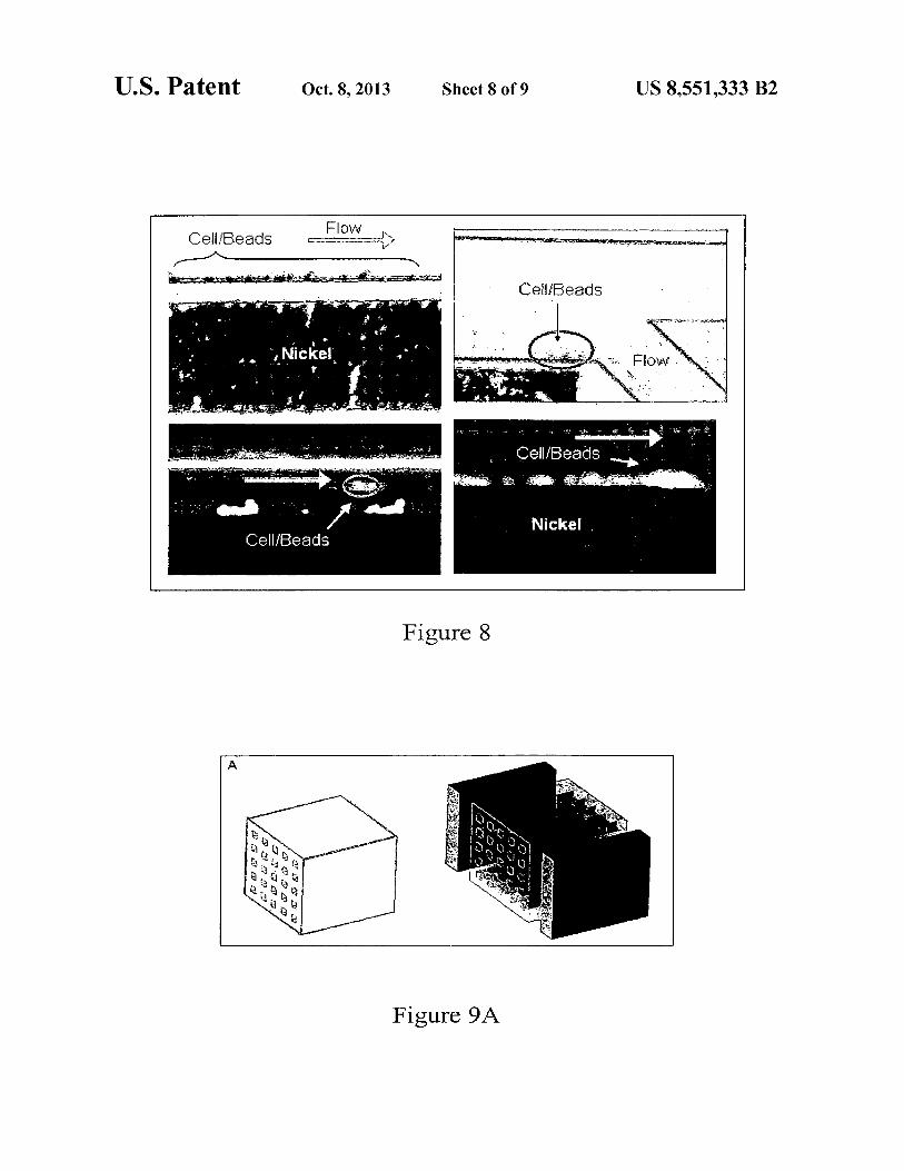
FIG. 8 shows that the cell/bead complexes stayed attached 35 114 in an embodiment of the current invention.) For example, to the bottom of the channel and were trapped. The upper two
the plurality of microparticles 114 may be mixed with a fluid pictures show the beads at the bottom of the channel. The and injected into a side channel 116 that is arranged proxi- bottom two pictures show cells with fluorescent markers at
mate the main channel 104. The plurality of microparticles the bottom of the channel. The arrows indicate the flow direc- 114 each includes a material that has a magnetic susceptibil- tion. The bottom left circle shows a cell moving away from 40 ity suitable to cause concentration of magnetic field lines of the main stream due to the induced force from the magnetic an applied magnetic field while the microfluidic device 100 is field gradient generated by the nickel particles. in operation. The microfluidic device 100 canbe connected to
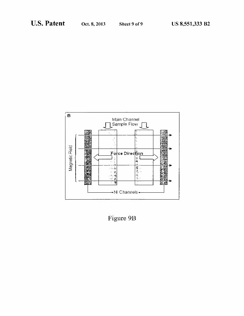
FIG. 9A is a schematic illustration of a cell separation cube, other microfluidic devices and can also have additional struc- which is an example of a microfluidic block according to an
tures in various embodiments of the current invention. For embodiment of the current invention. The small squares stand 45 example, the microfluidic device 100 may include hydrody- for an optimized microfluidic device containing a main chan- namic focusing channels 118 and 120. For channels that are nel and an adjacent metal particle channel. The two rectan- constructed sufficiently small, such as the main channel, fluid gular boxes are magnets that provide a magnetic field across
traveling through the main channel will exhibit laminar flow. the cube. The sample flows through the small squares in the
Fluid introduced into the hydrodynamic focusing channels cube. 50 118 and 120 will force the fluid already flowing through the
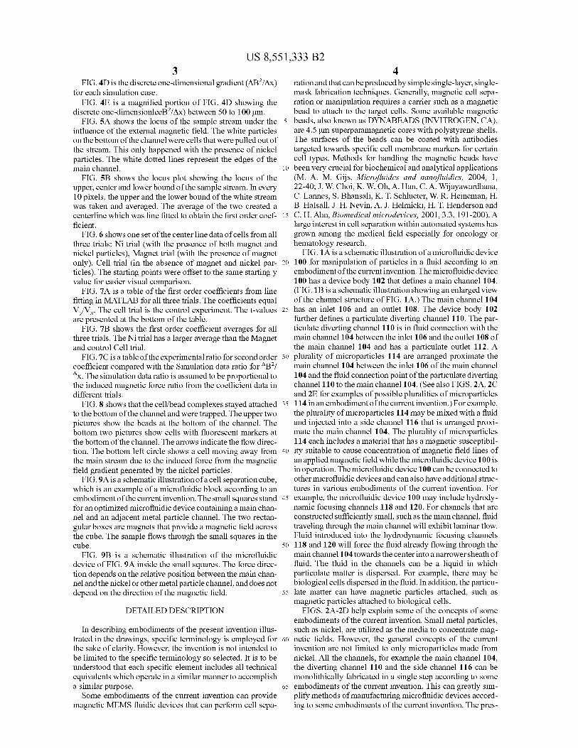
FIG. 913 is a schematic illustration of the microfluidic main channel 104 towards the center into a narrower sheath of device of FIG. 9A inside the small squares. The force direc-
fluid. The fluid in the channels can be a liquid in which tion depends on the relative position between the main chan- particulate matter is dispersed. For example, there may be nel and the nickel or other metal particle channel, and does not
biological cells dispersed in the fluid. In addition, the particu-
depend on the direction of the magnetic field. 55 late matter can have magnetic particles attached, such as magnetic particles attached to biological cells.
DETAILED DESCRIPTION
FIGS. 2A-2D help explain some of the concepts of some embodiments of the current invention. Small metal particles,
In describing embodiments of the present invention illus- such as nickel, are utilized as the media to concentrate mag- trated in the drawings, specific terminology is employed for 6o netic fields. However, the general concepts of the current the sake of clarity. However, the invention is not intended to
invention are not limited to only microparticles made from
be limited to the specific terminology so selected. It is to be nickel. All the channels, for example the main channel 104, understood that each specific element includes all technical
the diverting channel 110 and the side channel 116 can be
equivalents which operate in a similar manner to accomplish
monolithically fabricated in a single step according to some a similar purpose. 65 embodiments of the current invention. This can greatly sim-
Some embodiments of the current invention can provide plify methods of manufacturing microfluidic devices accord- magnetic MEMS fluidic devices that can perform cell sepa- ing to some embodiments of the current invention. The pres-

US 8,551,333 B2 5
ence of the nickel particles in an adjacent side channel increases the magnitude of the magnetic field density gradient which corresponds to an increase in the force exerted on the magnetic beads. Apart from the ease of device fabrication according to some embodiments of the current invention, stable and high recovery rates due to sophisticated force control within the microenvironment can be achieved in some embodiments. In addition, the fabrication cost for the device can be relatively low, which can lead to mass production and commercialization for clinical or research purposes. Theory
The magnetic force generated on a magnetic bead is gov-erned by the following equation (M. Zborowski, C. B. Fuh, R. Green, L. P. Sun, and J. J. Chalmers, Analytical chemistry, 1995, 67.20, 3702-3712):
6 magnetic beads bound to each surface marker ((3) is assumed to be a constant, which, in this case, equals 1. Second, we assume that the number of markers per area of cell surface (a) is also a constant. If one bead is bound to each cell, a equals
5 8.84x10⁹ beads/M2 (7.7. Chalmers, M. Zborowski, L. Moore, S. Mandal, B. B. Fang, and L. Sun, Biotechnology and bioengineering, 1998, 59.1, 10-20). Third, the susceptibility of the media (-10 -6) is negligible compared to the suscepti-bility of magnetic beads (0.245). Fourth, the diameter of the
10 cell is between 3 µm to 10µm. We assume the diameter of the cell is 6 µm. Other constants are permeability of free space, µ0=47tx10-7 Hm 1 , and the viscosity of media, q —_10-3 Nsxn i . By measuring the velocity ratio, we will be able to find the ratio of the total magnetic force on the cell/bead
15 complex.
Examples
Fb 2/ O AX
Vb V B2
(1)
where µ o is the magnetic permeability of free space; AZ is the difference of susceptibility between the magnetic bead and the surrounding medium; V b is the volume of the bead; and B is the magnetic field density. It is important to recognize that a gradient of magnetic field density is required for a transla-tional force. A strong uniform magnetic field can only cause rotational force, but not translational force.
The total force acting on a cell with magnetic beads attached is:
Fm =A,'a'P'F, (2)
where A, is the total surface area of the cell, a is the number of target cell surface markers per membrane surface area, R is the number of antibodies bound per marker, and the F m is the force acting on one magnetic bead.
Countering the magnetic force is the drag force defined by the Stokes drag law:
Fd-6jrq-ry (3)
where ,q is the viscosity of the medium; r is the radius of the cell; and v is the velocity of the cell moving through the medium.
Assuming that gravity and buoyant forces are negligible, the two forces combine into:
Fm +Fa ma (4)
where m is the mass of the cell and a is the acceleration of the cell. The inertial term (-10 - ") is several orders smaller than the total magnetic force and the Stokes drag force (-10-6) (S. Reddy, L. R. Moore, L. Sun, M. Zborowski and J. J. Chalmers, Chemical engineering science, 1996, 51.6, 947-956). Thus, we can neglect the inertial term in the equation (4). This assumption allows us to find the relationship between the lateral velocity that provides distinct separation and the minimum magnetic field density gradient ( v B2) required.
Plugging in equations (1), (2), and (3) into equation (4), the relation between the magnetic field gradient and the velocity of the cell moving in media is obtained:
VB'= 127r'uo-g-r
v (5)
A ' . a.13-AX' V b
By attempting to calculate the relationship between v B2 and v, the following assumptions were made. First, the number of
Material and Methods 20 Channel Fabrication
Different channel geometries were designed in conven-tional computer-aided design software and printed out onto a negative transparency mask (PHOTOPLOT, CO). The chan-nels were fabricated using replicate molding techniques. The
25 mold was fabricated using SU-8 negative photoresist (MI-CROCHEM, MA) on a silicon wafer. The thickness of the mold was —50 µm. Then, a polydimethylsiloxane mixture (PDMS), at a composition of 1 to 10 (weight ratio of curing agent to PDMS), was poured onto the mold and subsequently
30 cured at 60° C. for 4 hours. After the curing process, the PDMS replicate was peeled off and punched with inlets and outlets at designated locations. To complete the fabrication procedures, both the PDMS channel surface and a glass sub-strate were activated by oxygen plasma in order to bond the
35 two surfaces together (see FIGS. lA and 113). All inlets and outlets are 100 µm in width with the excep-
tion of outlet E, which is 150 µm. The main channel is 200 µm in width while the adjacent channel has a 100 µm width. The two channels are 25 µm apart. In addition, a 500 µL syringe
40 was used at inlet C while 250 µL syringes were applied for the rest of the inlet locations (A, B, and D). A sample, which was a mixture of cells and magnetic beads, entered the device from inlet B. Cell growth media was inserted from inlets A, C, and D. Inlet A was designed to serve the purpose of pushing
45 stagnated cells and beads that were stuck in inlet B into the main channel. Media from inlets C and D constitute two streams of sheath flows that focus the sample flow into a fine central stream through hydrodynamic focusing. This microf-luidic focusing technique allowed us to adjust the position
5o and the width of the sample stream in the same channel design.
System Setup Following the DYNABEAD protocol from INVITRO-
GEN, 25 µL of magnetic beads were added to 1 mL of B-lym- 55 phocyte sample (Coriell Institute, N7), at a cell density of
approximately 10 6 cells/mL and mixed for 30 minutes in a 1.5 mL microcentrifuge tube. Magnetic beads that are commonly found for analytical purposes are 4.5 µm in diameter and made from polystyrene superparamagnetic material (M. E.
6o Dudley, Journal of immunotherapy, 2003, 26.3, 187-189). The B-lymphocytes were cultured in RPMI 1640 (MEDIAT- ECH, VA) with 10% FBS and antibiotics 1xPSN (SIGMA- ALDRICH, MO). The cells were stained by an addition of 0.5 µL of MITOTRACKER red dye (INVITROGEN, CA). The
65 dye was excited by green light and fluoresced red light. Roughly 20% volume ratio of glycerol was added to the sample tube to prevent the precipitation of cell/beads com-

US 8,551,333 B2 7
plexes in the syringe during the experiment (X. Hu, P. H. Bessette, J. Qian, C. D. Meinhart, P. S. Daugherty, and H. T. Soh, Proceedings of the NationalAcademy of Sciences of the United States ofAmerica, 2005, 102.44, 15757-15761). 100 µL of prepared mix samplewas put in a 250 µL gas-tight glass syringe (Hamilton, Nev.) and connected to inlet B. Then growth media was filled into two 250 µL syringes (connected to inlets A and D) and a 500 wL syringe (connected to inlet C) (FIG. 3). Once the setup was completed, the syringes were connected to the microfluidic chip with soft tubing. (The microfluidic chip in this example is an example of a microf-luidic device 100 according to an embodiment of the current invention.) The chip was placed on an inverted microscope (NIKON TE2000U) that was connected to a CCD camera (AG HEINZE, CA). All the fluid media were pumped through digitally controlled syringe pumps (HARVARD APPARA-TUS, MA). The fluid pumping speed for the sample syringe (inlet B), along with one of the 250 µL media syringe (inletA) was set at 0.2 µL/min, while the other 250 µL media syringe (inlet D) and the 500 µL media syringe (inlet C) was set at 1 µL/min.
In order to demonstrate the functioning of the increased magnetic field gradient in the presence of nickel particles, three different conditions were tested: (1) in the absence of magnet and nickel particles (termed as Cell trial), (2) in the presence of a magnet but without nickel particles (termed as Magnet trial), and (3) with the presence of both magnet and nickel particles (termed as Ni trial). The Cell trial was the control experiment that served as a reference to compare with the later results. Comparison of the Magnet trial and the Ni trial determined the contribution of the nickel particles to the magnetic field gradient generation. The magnet in the experi-ments used was a NdFeB cube magnet with a side length of 4.76 mm (3/6') (AMAZING MAGNETS, CA). In order to hold the magnet in place on one side of the chip, another small plate magnet was placed in the other side of the chip with the dimensions of3.18 mmx3.18 mm' 1.59 mm ('/s"x'/s"x'/6'). For the Ni trial, the nickel particles, with less than 20 µm in diameter (Atlantic Equipment Engineers, N7), were immersed in silicone oil that carried the particles into the adjacent side channel from inlet G. Fluorescence images were taken at four different locations of the main channel to quan-titatively measure the locus of the cells that were subjected to external magnetic field. At each location, 15 pictures were taken with a 10 second exposure time. The pictures were used for further data analysis that will be explained in the next section.
Results Simulation To predict the performance of the resulting magnetic sepa-
ration scheme in the presence of nickel particles as a magnetic field concentrator, simulations were carried out using a sim-plified one-dimensional magnetostatic model by commercial software (COMSOL Multiphysics). In the simulation, a 100 µm length square magnet with 1 T was positioned behind the origin. Simulations showed that the magnetic field decreased dramatically within 100 µm from the magnet and remained at the same intensity level afterwards (FIG. 4A). This showed that the maximum force can only be obtained near the magnet (i.e. within 100 µm from the magnet). To implement this physically, magnets need to be fabricated in extremely close proximity to the sample channel in order for this scheme to be effective for cell separation. This involved a multi-layered MEMS fabrication scheme which would be costly and it complicated the device fabrication, prohibiting mass produc-tion of the device.
8 In another scenario, nickel particles were put in between
the magnet and the fluid to extend the effective range of the magnetic field, and the resulting effects were simulated. The presence of the nickel particles concentrates the magnetic
5 field by bending the field lines. This concentration of the magnetic field would cause a local substantial magnetic field gradient to occur, resulting in enhanced magnetic force on the magnetic beads (FIG. 413). From equation (1), the force is directly proportional to the gradient of the squared magnetic
10 field density (VB 2). The change of magnetic field density squared over the change of position (x) is shown in FIG. 4C. The ratio between the values of °B2/°x with nickel particles and without the particles showed that the addition of nickel
15 particles is expected to create a force that is roughly 20 times larger than that with magnets only. This ratio converges to around three at 200 M away from the edge of the magnet (FIG. 4D).
Data Analysis Since the images were taken in 4 different locations of the
~~ main channel, in order to reconstitute the locus of the sample stream, the images were combined using pre-defined align-ment points. The images from the first position did not have any usable alignment points; therefore, images from the other three positions were further analyzed. Pictures from each of
25 the three positions were randomly chosen and linked together to become partial channel images. The images were further processed to enhance the signal-to-noise level for later data analysis purpose (FIGS. 5A and 513). The locus of the sample stream was traced and drawn from the images. The bending of
so this locus was caused by the force pulling on the magnetic beads attached to the cells. From the center line data of all 15 pictures for the three different trials, the bending of the line from the Ni trial was significantly larger than the Magnet trial
35 and the Cell trial (FIG. 6). The velocity values were extracted from the image data to
quantify the difference between the three trials. The horizon-tal velocity of the complex (V,) is constant for each experi-ment since Vx depends on the flow rate of the sample and the
40 shear media. Considering Vx as a constant, the time traveled equals the position (x) over the horizontal velocity (V,). On the other hand, the vertical velocity (Vy) depends on the force exerted on the cell/bead complex. From equation (5), the total magnetic force is directly proportional to the velocity of the
45 complex. Since the vertical y range is comparably small, the magnetic force within this range can be assumed to be con-stant. Therefore, according to equation (5), the velocity of the cell/bead complex should be constant. The bending of the locus would provide us with the vertical velocity (Vy), gov-
50 erned by the equation:
Vy (6) Y= V 'x+Yo
55
where t is the travel time of the cell/bead complex, V x and Vy are exponents of velocity of the complex, and y o is the starting position of the sample stream. The ratio of the dimensionless first order coefficients in different trials can be used to quan-
60 tify and compare the vertical velocity which can be translated into the magnetic forces exerted on the complexes.
After running the data through a line fitting function (MAT-LAB), the average first order coefficient over the 15 sets of data for the Ni trial was 8.08x10 -3 with a standard error of
65 1.01x10⁻⁴ while the average for the Magnet trial was 2.44x 10⁻³ with a standard error of 2.66x10 -4. The Cell trial (i.e. the control experiment) had an average of 1.03x10 -3 with a stan-

US 8,551,333 B2 9
10 dard error of 2.57x10⁴ (see the table in FIG. 7A). The per- for the media and sample are important for dictating the centage of standard error over the average was only 1.2% for resulting cell separation performance. The design and posi- the Ni trial, 10.9% for the Magnet trial, and 25.0% for the Cell
tion of the adjacent nickel channel are important elements for
trial (FIG. 713). The ratio of the average Ni trial first order
improving the recovery rate for sample separation. Since the coefficient and the average magnet trial first order coefficient 5 nickel particles are self aligned, different nickel density was 3.26 (see the table in FIG. 7C). within the channel and different channel shape and design can
We performed a t-test to confirm the significance of our offer different effects. Occasionally, some cell/bead com- data. The t-value between the Ni trial and Magnet trial was plexes would be attracted towards the sidewall of the channel 19.79. The t-value between the Magnet trial and Cell trial was that was closed to the corner of the adjacent nickel channel. 3.81. The t-value between the Ni trial and Magnet trial was io This phenomenon further supports that stronger magnetic 25.55. A t-value of 2.76 corresponded to a p-value of 0.01 for
force field can be generated with reduced separation distance
a two-tailed test. Therefore, the p-value for the Ni/Magnet
between the channels (FIG. 8). trial and the Ni/Cell trial should be significantly lower then
Some embodiments of the current invention have advan-
0.001. Even though the t-value for the Magnet/Cell trial was tages over the conventional micro-magnetic cell separation larger than 2.76, the p-value would be closer to 0.01 than the 15 devices, such as relatively low cost of production. Recent other p-values since the t-values for the other two compari- magnetic bead manipulation platforms require intensive sons were 5 times greater. However, overall, the three trials
MEMS fabrication technology which are economically
were considered statistically different. expensive and time consuming (Q. Ramadan, V. Samper, D. P. The experimental results in conjunction with the simula- Poenar and C. Yu, Biosensors & bioelectronics, 2006, 21.9,
tion results help demonstrate that the presence of small metal 20 1693-1702; K. H. Han, andA. B. Frazier, Lab on a chip, 2006, particles, such as nickel, in an adjacent channel according to
6.2, 265-273; D. W. Inglis, R. Riehn, R. H. Austin, and J. C.
an embodiment of the current invention was able to generate
Sturm, Appliedphysics letters, 2004, 85.21, 5093-5095; J. W. a large magnetic field gradient, translating into an enhanced
Choi, Biomedical microdevices, 2001, 3.3,191-200; J. Miwa,
magnetic force for cell/bead manipulation or separation. The
W. H. Tan, Y. Suzukui, N. Kasagi, N. Shikazono, K. furukawa, average ratio of the first order coefficients in the Ni and 25 and T. Ushida, The First International Conference on Bio- Magnet trials showed that the induced magnetic force in the
Nano-Information Fusion, Marina del Ray, Calif., 2005).
presence of nickel particles were more than three times stron- Fabrication methods according to some embodiments of the ger compared to the absence of the nickel particles. The current invention are replicate molding techniques which averages were shown to be significantly different from the only require a single mask layer for the manufacturing pro- t-test. However, from the t-values, the statistical difference 30 cess. However, general concepts of the current invention are between the Magnet trial and the Cell trial was considerably not limited to only single-mask-layer fabrication. In addition, smaller than difference between the Ni trial and the Magnet
the mold can be reused multiple times to fabricate new chan-
trial or the Cell trial. The p-value for Magnet/Cell trial was nels for testing and optimizing the system. only slightly lower than 0.01. In addition, the percentage of
Upon optimizing channel designs formaximized cell sepa-
standard error over the averages of the Magnet (11 %) and Cell 35 ration recovery rate and purity, other embodiments of the trials (25%) showed that the variations among the sample current invention can include producing high-throughput were greater than the averages from the Ni trial (1 %). For the microfluidic cell separation arrays. For example, other case of the Cell trial, the relatively large standard deviation embodiments of microfluidic devices according to the current was believed to originate from the random diffusion of the
invention can be a microfluidic chip that has a plurality of
complexes or instability of the system such as disturbance 40 structures such as those of the microfluidic device 100. This from the tubing. Similar to the case of the Cell trial, the 11 %
may be a planar array, for example, which could be produced
standard error over average from the Ni trial showed that as a single or multiple microfluidic chips. Another embodi- systems using pure magnets would have a great deal of varia- ment of the current invention may include, for example, an tion. In comparison, the presence of nickel particles in an array of microfluidic channels fabricated in a plastic or acrylic adjacent channel as a magnetic field concentrator has pro- 45 cube to provide a microfluidic block (FIG. 9A). This cube- vided an enhanced force field for particle manipulation as shaped cell separator (microfluidic block) can provide a large well as maintaining a more stable and controllable system. throughput while maintaining a well controlled microenvi-
The experimental force ratio of the Ni trial/Magnetic trial
ronment for separation. These cell separator arrays can be was larger than the simulated results. From the fluorescent
disposable due to their low manufacturing cost. In addition,
images, the measured distance between the sample stream 50 multiple cell separation events can be performed in one single and the adjacent channel is 151 µm. Since the borderline of
step upon the application of the magnetic field according to
the last nickel particle was at 50 µm in the simulation, the ratio some embodiments of the current invention. The choices of of °B2/°x of interest is at 201 µm. According to the simulation the metal particles are relatively flexible, provided that their data, the ratio of ° B2/° x at 201 µm had the value of 2.64. (See permeabilities are large enough for the device to be effective. the table in FIG. 7C.) The ratio of ° 132/ ° x can be assumed 55 An automated separation system according to some embodi- equivalent to the force ratio because the magnetic field den- ments of the current invention can be further coupled with a sity gradient is the dominant factor in the magnetic force microfluidic cell and magnetic bead mixer (H. Suzuki, C. M. equation. The experimentally determined force ratio of 3.31
Ho, N. Kasagi, Journal of microelectromechanical systems,
was noticeably greater than the simulated result (i.e. force
2004, 13.5, 779-790). Practitioners using a device according ratio=2.64), suggesting that more prominent effects can be 60 to this embodiment of the current invention are only required achieved with closer separation between the sample and the to provide suitable magnetic beads and place the sample in the adjacent channels (FIG. 41)). specified container. The separation can then be done auto-
Although this proof-of-concept prototype has proven the matically. Such a system can be useful for researchers who desired effects, a number of improvements can be done to want to study certain cell types or bio-particles from a tissue maximize the performance of the device according to some 65 or blood sample. embodiments of the current invention. Parameters such as the
Other aspects of the current invention can include cell
length and width of the main channel as well as the flow rates trapping and cell/particle concentration in addition to cell/

US 8,551,333 B2 11
particle separation, for example. Generally, it can provide a new device and methods for manipulating particles. It can also be integrated into devices for rare blood cell isolation, specific stem sell isolation and stimulated to fully differenti-ate at the outlet, DNA or other biomolecule concentration and 5
detection, etc. Furthermore, the channel design can be selected according
to the specific application it is targeted toward. For example, once the geometry is optimized for high efficient magnetic bead-based cell separation, the device can be particularly io helpful for hospitals and biology laboratories to replace dif-ferential centrifugation separation. Since the device can be made out of acrylic or other plastic blocks, it can be disposed of after every use. The entire cell separation system can be automated, reducing time for researchers or technicians. 15
Other applications include using the magnetic force to trap individual cells for research purposes as well as designing the geometry for rare blood cell isolation or even cancer cell isolation.
The nickel can be replaced with other types of metal for the 20
microparticles that have higher susceptibility, such as, but not limited to, iron. Iron is hard and currently costly to microfab-ricate with traditional methods, but it can be easily and eco-nomically used in some embodiments of this invention. Simi-lar to magnetic fields, electric fields may also be bent or 25
manipulated using different particles to create dielectro-phoretic forces. Other side channel geometries can allow different applications such as single cell trapping, biomol-ecule detection or concentration, magnetic particle assembly, etc. 30
According to other embodiments of the current invention, metal particles can be introduced into one or multiple shear streams, such as the hydrodynamic focusing streams. Even though this may contaminate the sample and might be bio-logically incompatible in some applications, the particles in 35
the shear streams could be a good method for applications that require a stronger magnetic force in some embodiments of the current invention.
The throughput volume range for devices and systems according to some embodiments of the current invention can 40
be very large. If small volume processes, such as for pediatric research, are required, a device according to an embodiment of the current invention could process a volume in the micro-liter range since the flow rate for the sample is less than 1 µL/min. Different small volumes can also be processed by 45
changing the channel width and length. If large volume pro-cesses, such as blood screening, are required, the devices can be made in arrays to work parallel. The array can be made from a plastic cube such as acrylic, for example, and the separation channel and side channel can be fabricated with 50
lasers according to one embodiment. The devices can be made on top of each other and can use only one external magnetic source in some embodiments of the current inven-tion (see FIG. 9, for example).
The current invention is not limited to the specific embodi- 55
ments of the invention illustrated herein by way of example, but is defined by the claims. One of ordinary skill in the art would recognize that various modifications and alternatives to the examples discussed herein are possible without depart-ing from the scope and general concepts of this invention. 60
What is claimed is: 1. A microfluidic device for manipulation of particles in a
fluid, comprising: a device body defining a main channel therein, said main
channel comprising an inlet and an outlet; said device 65
body further defining a particulate diverting channel therein, said particulate diverting channel being in fluid
12 connection with said main channel between said inlet and said outlet of said main channel and comprising a particulate outlet; said device body further defining a side channel therein, said side channel proximate and not connected to said main channel;
• fluid disposed within said side channel; and • plurality of microparticles dispersed in said fluid, wherein said plurality of microparticles each comprises a
material in a composition thereof having a magnetic susceptibility suitable to cause concentration of mag-netic field lines of an applied magnetic field while in operation.
2. A microfluidic device according to claim 1, wherein said plurality of microparticles comprise at least one of nickel and iron in a composition thereof.
3. A microfluidic device according to claim 1, wherein said device body is a microfluidic chip, said main channel and said diverting channel being arranged substantially along a com-mon plane within said microfluidic chip.
4. A microfluidic device according to claim 3, further com-prising a plurality of hydrodynamic focusing channels con-nected to said main channel defined by said microfluidic chip, wherein all of said hydrodynamic focusing channels are arranged substantially along a common plane within said microfluidic chip.
5. A microfluidic device according to claim 1, wherein said device body is a microfluidic chip, said main channel, said diverting channel and said side channel being arranged sub-stantially along a common plane within said microfluidic chip.
6. A microfluidic device according to claim 1, wherein said device body is a microfluidic block.
7. A microfluidic particle-manipulation system, compris-ing:
• microfluidic particle-manipulation device; and • magnet disposed proximate said microfluidic particle-
manipulation device, wherein said microfluidic particle- manipulation device comprises: a device body defining a main channel therein, said main
channel comprising an inlet and an outlet; said device body further defining a particulate diverting
channel therein, said particulate diverting channel being in fluid connection with said main
channel between said inlet and said outlet of said main channel and comprising a particulate outlet; said device body further defining a side channel therein, said side channel proximate and not connected to said main chan-nel; • fluid disposed within said side channel; and • plurality of microparticles dispersed in said fluid, and
wherein said plurality of microparticles each comprises a material in a composition thereof having a magnetic susceptibility suitable to cause concentration of mag-netic field lines of an applied magnetic field while in operation.
8. A microfluidic system according to claim 7, wherein said plurality of microparticles comprise at least one of nickel and iron in a composition thereof.
9. A microfluidic system according to claim 7, wherein said device body is a microfluidic chip, said main channel and said diverting channel being arranged substantially along a com-mon plane within said microfluidic chip.
10. A microfluidic system according to claim 7, wherein said device body is a microfluidic chip, said main channel, said diverting channel and said side channel being arranged substantially along a common plane within said microfluidic chip.
US 8,551,333 B2 13 14
11. A microfluidic system according to claim 9, further comprising a plurality of hydrodynamic focusing channels connected to said main channel defined by said microfluidic chip, wherein all of said hydrodynamic focusing channels are arranged substantially along a common plane within said s microfluidic chip.
12. A microfluidic system according to claim 7, wherein said device body is a microfluidic block.