passive design toolkit - vancouver.ca · passive design toolkit for homes bc hydro is a proud...
TRANSCRIPT

FOR HOMES
Passive Design Toolkit

Passive Design Toolkit for Homes
BC Hydro is a proud supporter of the Passive Design Toolkits for the City of Vancouver.
We recognize that part of providing clean energy for generations is helping British Columbians build Power Smart high performance buildings.
We thank you for using this Toolkit in your project, and congratulate the City of Vancouver for providing leadership in helping designers create the buildings of tomorrow in BC today.
Lisa Coltart, Executive Director Power Smart and Customer Care
Cover Photo: Battersby Howat Photographer: Michael Boland
Hand Illustrations: Matthew Roddis Urban Design
Prepared by:
Light House Sustainable Building Centre and Dr. Guido Wimmers.
July 2009
Vancouver City Council has taken an important first step toward our goal of becoming the greenest city in the world, as the first jurisdiction in North America to go beyond green building codes and use architecture itself to reduce greenhouse gases (GHGs).
More than half of all GHG emissions in Vancouver come from building operations, so the City has set a target that all new construction will be GHG neutral by 2030, through carbon-neutral measures in areas such as lighting and heating technologies.
The Passive Design Toolkits will serve as a resource to the development industry, and as a framework for the City’s Planning department to review and update its design guidelines. Passive design elements, when evaluated in terms of relative cost and effectiveness, have been shown to reduce a building’s energy demand by as much as 50 percent.
The new Toolkits will help us create a more sustainable architectural form across the city, while improving the comfort of the people who live and work in new buildings.
Gregor Robertson
Message from BC Hydro
Message from the Mayor
City of Vancouver — Passive Design Toolkit - for Homes

Passive Design Toolkit for Homes
Page i
Contents1. Introduction ....................................................................1
How to use this toolkit: .................................................................................. 1
2. Passive Solar Power .........................................................3
2.1 Solar Access .............................................................................................42.2 Energy Efficiency and Thermal Comfort ..................................................5
3. Orientation .....................................................................7
3.1 Building Shape ......................................................................................... 73.2 Ideal Elevations ........................................................................................83.3 Landscaping ........................................................................................... 10
4. Interior Layout .............................................................. 13
4.1 Kitchens ................................................................................................. 134.2 Living Spaces ......................................................................................... 134.3 Bedrooms .............................................................................................. 134.4 Mechanical Systems .............................................................................. 13
5. Insulation ..................................................................... 15
5.1 Insulation Materials ............................................................................... 165.2 Selecting Insulation Materials ................................................................ 225.3 Airtightness ........................................................................................... 235.4 Thermal Bridges..................................................................................... 235.5 Assemblies .............................................................................................24
6. Windows (glazing) ......................................................... 25
6.1 Thermal Quality and Style of Window .................................................... 256.2 Location and Size of Windows ...............................................................286.3 Shading .................................................................................................28
7. Lighting ........................................................................ 31
7.1 Interior Layout and Windows .................................................................. 317.2 Skylights vs. Solar Tubes ........................................................................ 317.3 Clerestory Windows ............................................................................... 317.4 Paint as a Passive Lighting Strategy ....................................................... 33
8. Ventilation .................................................................... 35

Passive Design Toolkit for Homes
Page ii
8.1 Window Placement ................................................................................ 358.2 Stack Effect and Cross Ventilation .......................................................... 358.3 Window Style ......................................................................................... 368.4 Heat Recovery Ventilators...................................................................... 36
9. Thermal Mass ................................................................39
9.2 Slab on Grade Construction ...................................................................40
10. Density ....................................................................... 43
11. Benefits of Passive Design ............................................ 45
Case Study ..................................................................................................46
Bibliography .....................................................................48
i. City of Vancouver Policy Context ..................................... 51
Green Homes Program ................................................................................ 51Part 3 Buildings ........................................................................................... 52EcoDensity .................................................................................................. 52Climate Neutral Network ............................................................................ 53
ii. Acronyms and terms used in this report ..........................54
Contents Continued...
How to use this toolkit:
This toolkit has been written to inform City staff and the design and development communities about passive design. While covering best practices, the toolkit addresses the specific needs of Vancouver and outlines a succinct definition of what ‘passive’ means for Vancouver. This toolkit can be used as a reference for best practices, and considered complementary to design guidelines and policy.
The principles of passive design are not new and are, in fact, based on simple, proven concepts. Passive design refers to an approach that discourages reliance on mechanical systems for heating, cooling and lighting and instead harnesses naturally occurring phenomenon such as the power of the sun, direction of wind and other climatic effects to maintain consistent indoor temperatures and occupant comfort. By leveraging the natural environment, buildings that incorporate passive design can:
help to reduce or even eliminate utility bills
improve the comfort and quality of the interior environment
reduce GHG emissions associated with heating, cooling, mechanical ventilation and lighting
reduce the need for mechanical systems, thereby reducing the resources required to manufacture

Passive Design Toolkit for Homes
Page 1
1. Introduction
How to use this toolkit:
This toolkit has been written to inform City staff and the design and development communities about passive design. While covering best practices, the toolkit addresses the specific needs of Vancouver and outlines a succinct definition of what ‘passive’ means for Vancouver. This toolkit can be used as a reference for best practices, and considered complementary to design guidelines and policy.
The principles of passive design are not new and are, in fact, based on simple, proven concepts. Passive design refers to an approach that discourages reliance on mechanical systems for heating, cooling and lighting and instead harnesses naturally occurring phenomenon such as the power of the sun, direction of wind and other climatic effects to maintain consistent indoor temperatures and occupant comfort. By leveraging the natural environment, buildings that incorporate passive design can:
help to reduce or even eliminate utility bills
improve the comfort and quality of the interior environment
reduce GHG emissions associated with heating, cooling, mechanical ventilation and lighting
reduce the need for mechanical systems, thereby reducing the resources required to manufacture
these systems, as well as the costs associated with their purchase or operation
make alternative energy systems viable
Homes designed using passive strategies do not have to look aesthetically different from those that are designed without consideration for climatic factors, but occupants of a passive home will experience greater thermal comfort while paying lower energy bills. The most rigorous European standard, PassivHaus, regulates input energy to a maximum 15 kWh / m2/ year for heating/cooling/ventilation – about one tenth of that in a typical new 200 m2 Canadian house, and a difference equivalent to 300 litres of oil, 300m3 of natural gas or 3000 kWh of electricity annually.
This toolkit outlines passive design practices for low-rise wood framed construction buildings in Vancouver.
Homes designed using passive strategies do not have to look aesthetically different
photo: Hotson Bakker Boniface Haden

Passive Design Toolkit for Homes
Page 2
Passiv Haus is a specific design standard developed in Austria and Germany. A building that qualifies for this standard has to meet clearly defined criteria, which include (for a building constructed at Northern European latitude of 40-60˚):
A total energy demand for space heating and cooling of less than 15 kWh / m2 / year
A total primary energy use for all appliances, domestic hot water and space heating and cooling of less than 120 kWh / m2 / year
The total primary energy use includes the efficiency of the energy generating system
A Passiv Haus building shares common core features with other passive design buildings, relying on four common strategies:
A high level of insulation, with minimal thermal bridges
A high level of utilization of solar and internal gain
A high level of air tightness (See Chapters 5.3 and 5.4 for a discussion on Thermal Bridges and Air Tightness)
Good indoor air quality (which may be provided by a whole house mechanical ventilation system with highly efficient heat recovery)
The Passiv Haus approach was used extensively as a reference in developing this toolkit.
For further information on the Passiv Haus system please visit www.passiv.de
A passive design can reduce total energy demand for space heating and cooling to less than 15 kWh / m2 / year.
When approaching the design for a building, the following questions can be considered:
‘How important is occupant comfort for this building?’
‘How important is occupant health in this building?’
‘How important is the environmental footprint of the building?’
‘How future proofed is the building design?’
‘How will the building make use of natural climatic factors?’
photo: Lang Wilson Practice in Architecture Culture/Nic Lehoux

Passive Design Toolkit for Homes
Page 3
2. Passive Solar PowerThe sun emits energy as electromagnetic radiation 24 hours per day, 365 days per year, at a rate equivalent to the energy of a 5725˚C furnace. In fact, each year the sun can supply nearly 36,000 times the amount of energy currently provided by total world oil consumption.
The sun’s energy is radiated to the earth in the form of visible light, along with infrared and ultra-violet radiation which are not visible to the naked eye. When this radiation strikes the earth’s surface, it is absorbed and transferred into heat energy at which point passive heating occurs. The rate at which solar energy reaches a unit area at the earth is called the ‘solar irradiance’ or ‘insolation’.
Vancouver has a ‘moderate oceanic’ climate and is classified as heating dominated. This means
that buildings require more days of heating than cooling. Fortunately, Vancouver does not experience extreme heat or cold conditions for long durations, making passive design less challenging. Even though Vancouver receives plenty of sun in the summer, it receives very little sun from November to March and is challenged to benefit greatly from passive winter solar gain (unlike cold and sunny Edmonton winters). Winter also sees early sunsets and late sunrises, while in the height of summer Vancouver experiences long daylight hours (up to 16.5 hours).
Fortunately, Vancouver does not experience extreme heat or cold conditions for long durations, making passive design less challenging in this city.

Passive Design Toolkit for Homes
Page 4
Due to the low levels of solar exposure, passive design should include a combination of solar heating with passive cooling and shading in the Vancouver climate.
In consideration of Vancouver’s climate, this toolkit will focus on maximizing solar gains in winter, and will include some recommendations for avoiding unwanted solar gain in the summer.
Table 1: Solar Radiation
Jan Feb Mar Apr May Jun Jul Aug Sep Oct Nov Dec YearHeating Degree Hours - Exterior (kKh) 13.9 11.1 10.8 8.3 6 3.7 2.5 2.6 4.8 8.2 10.9 13.3 96Heating Degree Hours - Ground (kKh) 6.4 6.2 6.7 5.9 5.2 2.9 2.2 1.8 2.9 3.7 4.4 5.6 54Losses - Exterior (kWh) 1413 1130 1095 846 615 380 255 263 487 837 1115 1350 9787Losses - Ground (kWh) 180 173 189 166 145 82 62 51 82 102 125 157 1515Sum Spec. Losses (kWh/m3) 7.7 6.3 6.2 4.9 3.7 2.2 1.5 1.5 2.7 4.5 6 7.2 54.3Solar Gains - North (kWh) 30 53 87 118 171 197 186 140 95 64 38 23 1202Solar Gains - East (kWh) 1 2 4 5 7 7 8 7 5 3 1 1 52Solar Gains - South (kWh) 311 438 600 559 652 588 640 692 680 507 300 231 6199Solar Gains - West (kWh) 2 4 6 8 12 12 13 11 8 5 2 2 86Solar Gains - Horiz. (kWh) 0 0 0 0 0 0 0 0 0 0 0 0 0Solar Gains - Opaque (kWh) 21 39 76 105 155 162 167 138 94 52 24 15 1047Internal Heat Gains (kWh) 367 331 367 355 367 355 367 367 355 367 355 367 4318Sum Spec. Gains Solar + Internal (kWh/m3) 3.5 4.2 5.5 5.5 6.6 6.4 6.6 6.5 5.9 4.8 3.5 3.1 62Utilisation Factor (kWh) 100% 98% 92% 81% 55% 35% 23% 23% 46% 85% 99% 100% 63%Annual Heat Demand (kWh) 863 453 234 77 6 0 0 0 1 94 526 871 3125
Climate: Vancouver Building: Kitsilano Residence
Interior Temperature: 20 C Treated Floor Area: 208 m2
A 150m² passively designed house (2 storey) would need 15 kWh/m²/year or less for heating. This is 150 m² x 15kWh = 2250 kWh in total per year for heating. The roof area of this home would be 75 m². 75 m² x 0.78 (solar radiation) x 31 December days = 1800 kWh. Theoretically the energy from the sun given in December would be almost enough for the whole year!
2.1 Solar Access
Solar access describes the amount of useful sunshine reaching a building. This value varies depending on climate, and can be impacted by the location of the sun and surfaces which surround a building.
The angle at which the sun strikes a location is represented by the terms altitude and azimuth. Altitude is the vertical angle in the sky (sometimes

Passive Design Toolkit for Homes
Page 5
Altitude and Azimuth
referred to as the height); azimuth is the horizontal direction from which it comes (often referred to as the bearing). Altitude angles can vary from 0˚ (horizontal) to 90˚ (vertically overhead). Azimuth is generally measured clockwise from north so that due east is 90˚, south 180˚ and west 270˚.
Solar access describes the amount of useful sunshine reaching a building.
Sun Chart
7pm
4pm5pm
4pm
2pm10am
8am
8am7am
5am
JUNE
JUNE /SEPT
DECEMBER
NOON
MAIN SOLAR COLLECTING HOURS
As solar radiation strikes the earth, it is reflected by surrounding surfaces. This is called reflected radiation. Light coloured surfaces reflect more than dark ones.
It is important to understand the pattern of the sun in relation to specific latitudes. A sun chart is the simplest way to determine where the sun is at specific dates and times throughout the year. In order to better determine solar access, there are also computer programs which can manipulate data from charts and formulas.
2.2 Energy Efficiency and Thermal Comfort
Though comfort can be highly subjective, The American Society of Heating Refrigeration and Air-Conditioning Engineers (ASHRAE) defines thermal comfort as the state of
mind that expresses satisfaction with the surrounding environment (ASHRAE Standard 55), and in this application, thermal comfort is achieved within a narrow range of conditions.
Factors such as temperature, ventilation, humidity and radiant energy affect thermal comfort, and for humans the comfort zone is within a very narrow range of conditions. Exterior climate conditions can also alter the acceptable interior conditions.
Building occupants are most comfortable when given the opportunity to adapt or have control over their environments (when they can open a window, put on a sweater, pull down the window blinds). Energy efficiency is achieved when occupant comfort is maintained through limited reliance on mechanical space conditioning. Thermal comfort rating software can model the amount of energy required to maintain comfortable temperatures within a building to size mechanical systems appropriately.
E = 90oS = 180o
W = 270o
N = 0o
altitude
azimuth
horizon
Light coloured surfaces reflect more than dark ones.
Dark and light surfaces

Passive Design Toolkit for Homes
Page 6
By planning for passive design, we can reduce the energy requirements of our built environment and improve thermal comfort for occupants. Passive design is not a new concept – ancient and medieval construction practices used abundant natural climatic conditions to passively control indoor temperatures.
Synergies/Barriers: Designing for passive gains needs to be done keeping in mind best practices in construction – if a building is more air tight and leaks less energy, it must also be properly ventilated. If a building is to gain from south facing windows in the winter, it must also be shaded from the sun in the summer.
Passive Solar Power Energy efficiency is achieved when occupant comfort is maintained through limited reliance on mechanical space conditioning.
photo: Lang Wilson Practice in Architecture Culture/Nic Lehoux

Passive Design Toolkit for Homes
Page 7
3. OrientationGood building orientation in relation to the earth’s axis and a site’s geographical features can improve passive gains and thereby reduce the need for mechanical heating or cooling systems. This can also result in lower energy bills, and lower related GHG emissions.
Sites which are aligned along an east-west axis are ideal, as they receive good solar access while neighbouring houses provide protection from the eastern and western sun in the summer.
Broadly speaking, homeowners may have little or no control over optimizing site selection and orientation; the former depending on availability of property or land and the latter determined by municipal zoning. For instance, in Vancouver and many North American cities, a grid-oriented system predominates and in Vancouver the majority of homes are oriented north-south on east-west streets.
Still, small shifts in decisions around orientation, based on climatic and regional conditions, can help to optimize passive gains and maximize use of the free energy generated by the local environment.
3.1 Building Shape
To maximize the benefits of passive design, a design must first and foremost minimize overall energy consumption requirements. A building design which keeps corners and joints to a minimum reduces the possibility of creating thermal bridges through which heat can dissipate to the outside of a building (see discussion in Chapter 5.4, thermal bridges).
Vancouver’s Street Grid
In Vancouver the majority of homes (both house and condominiums) are oriented north-south on east-west streets.
2000 sq ft
2000 sq ft
Complex layouts lead to more corners and joints which leak energy. It also creates more surface areas which can lose heat
Efficient layout
Inefficient layout
N

Passive Design Toolkit for Homes
Page 8
Compactness is a measure of floor space relative to building envelope area. A compact design maximizes living space within a minimum envelope area. The envelope or shell of the building is where heat loss occurs. Restricting the number of exterior walls also ensures that the amount of wall exposed to the elements is kept to a minimum. In an ideal case, a building design will seek to maximize the ratio of usable floor area to the outside wall area (including the roof). The theoretical ideal form would be a sphere, because this is a maximized volume versus a minimum envelope. The next most usable form would be a cube, with every permutation from the ideal a step towards weakening the theoretical performance of the building.
Single family homes are usually not as high as they are wide or long. This varies from the ideal, thus major prominences and offsets should be avoided. These not only
increase the envelope surface, but also lead to creation of heat bridges and are harder to maintain. Rowhouses and townhouses are another form of design which achieve maximum floor area and minimize opportunities for heat loss.
Utilize a compact design in order to minimize exterior wall surface area and associated heat gain/loss potential
A shape as close to a square as possible is optimum to minimize corners and maximize floor area in relation to outside wall area
3.2 Ideal Elevations
Orientation can affect the angle at which the sun enters windows, causing overheating in the summer. Attention to overhangs can be useful when a building is poorly oriented. Building homes side by side and to the property line will also affect orientation considerations.
The angle of solar radiation as it enters a window (angle of incidence) will affect the degree of passive solar gain that radiation delivers.
When the sun is low in the sky, the light hits the window perpendicular to the glass. In this case, the heat gain is at a maximum. As the sun is higher in the sky, the angle is increased, reflecting more of the light. In this instance, less heat is transferred to the building. Windows on the south elevation can generally best exploit the sun.
Ideal Orientation
South facing windows allow for winter heat while strategically placed deciduous trees and overhangs will shade the hot summer sun. Neighbouring properties can effect solar access and wind pattern.
WINTER SUN
SUMMERSUN
WIND

Passive Design Toolkit for Homes
Page 9
Summer Sun (overhang creates
cooling shade)
Winter Sun (sunlight warms
directly)
Southern elevation
To maximize the potential for solar gain through the winter months, a building should orient the longest elevation towards the south. (In design terms, south is considered to be anywhere within 30° east or west of true south.)
In addition, to reduce unwanted solar gain in the summer, designing for flexible sunscreens or overhangs for windows on these south facing elevations will ensure that the sun can be shaded during the warmer months.
Fixed overhangs should be designed to have a depth of roughly 50% of the height from the glass to the tip of the overhang. As the sun in summer is higher than in winter along the south elevation, a properly sized overhang can shade a south window for most of a summer day, without blocking out the low angled winter sun.
Maximize the window area on the south elevation
Avoid winter shadows from coniferous trees, other buildings, or other obstacles that will create shadows during the short winter days
Eastern and Western Elevations
To reduce unnecessary solar gain in the summer, a design should minimize window or wall area facing east or west.
Windows on the east elevation are exposed to solar gain throughout the year, while west facing windows will provide too much solar gain in the summer and insignificant gains in the winter.
At the same time, cold winter winds coming primarily from the east should also be taken into consideration.
East facing windows should be limited in size, or protected by overhangs or trees
West facing windows should be avoided unless they can be fully shaded during the summer months
Planting deciduous trees on the east and west sides will shade the home in the summer, and allow winter light in when they drop their leaves
The majority of residential lots in Vancouver are oriented such that the east and west facades are shaded by
Overhang
A properly sized overhang can shade a south window for most of a summer day, without blocking out the low angled winter sun
Because the winter sun is at a lower angle, sun can travel directly into the building warming it during the cool months. The high summer sun is blocked by the overhang creating a cooling shade.

Passive Design Toolkit for Homes
Page 10
neighbouring houses.
Landscaping with evergreen trees or tall hedges can help provide a windbreak
Northern Elevation
The north elevation provides the highest quality of daylight – diffused natural light.
Design wall areas as primarily solid, with windows located where needed for daylighting and ventilation requirements
Protect and insulate this elevation to prevent unwanted winter heat losses
Take advantage of adjacent buildings to protect the building from heat losses
3.3 Landscaping
Landscaping can aid passive design strategies
Plant shade trees in the appropriate locations to block or filter harsh winds
Vegetation that blocks winter sun should be pruned, deciduous trees should be planted as they shed their leaves in winter, allowing in the sun
Balconies on the south, if designed incorrectly, can restrict access to the winter sun
Deciduous vines in combination with overhangs can provide self adjusting shading. Vines on walls can also provide summer insulation but this strategy is complicated as vines can also compromise the building envelope
Plants can be used instead of paving to mitigate heat island effect in the summer
Green roofs serve to moderate internal building temperature as well as to mitigate heat island effect. A study by the City of Toronto found that green roofs provide significant economic benefits in the areas of stormwater management and reduction of heat island (and the energy use associated with them). http://www.toronto.ca/greenroofs/findings.htm
There are several types of green roof systems, and many do not use new technology. Any green roof should be installed and maintained with care, and it is highly critical that a structural analysis of the building be completed prior to installation.

Passive Design Toolkit for Homes
Page 11
Ideal building orientation may be constrained by municipal planning layout requirements. A building can still use passive design strategies through careful consideration of the placement of windows and the design features used for shading and ventilation.
Synergies/Barriers: As orientation is dictated by municipal planning, design becomes an important consideration – building design should acknowledge site limitations and compensate for them.
Impact on Energy Efficiency: Even small changes in orientation and attention to details such as overhangs can be very effective.
Orientation:
Deciduous trees provide cooling shade in the summer and, after shedding their leaves, allow for warm sun to enter the building in the winter
Orient the “main” side towards the south ± 30° East or West, and use large south-facing windows
Keep east, north and west window space small, while also using fewer windows in total (see discussion under windows, chapter 6)
Minimize unwanted shade to allow passive solar energy use
Use landscaping consistent with required amounts of shading at different times of the year – deciduous trees will offer shade in summer but access to solar heat in winter
Use a compact building form to limit heat loss
Provide operable windows on all building elevations
Row and multi-story building designs can maximize efficiencies
Key Design Strategies
Cost:

Passive Design Toolkit for Homes
Page 12
photo: Battersby Howat/Michael Boland

Passive Design Toolkit for Homes
Page 13
4. Interior LayoutGood interior layout will facilitate many of the passive strategies recommended in this toolkit, in particular thermal mass, lighting and ventilation considerations.
4.1 Kitchens
Kitchens should ideally be located within the building in such a way as to avoid over-heating, either the kitchen itself or the rest of the building. One way to ensure this is to avoid placing kitchens on the western elevation. In most instances, this will cause over- heating in the warm summer months. An ideal location for a kitchen is on the eastern side of the building. This catches the morning sun but not the warmer, late afternoon sun. Northern elevations or central spaces within the building are also ideal for kitchens that are heavily used, though kitchens in central spaces need to ensure appropriate ventilation.
Situate the kitchen on the eastern or northern elevation, or in a central space within the building
4.2 Living Spaces
Rooms that are occupied predominantly in the evening
should be located on the western side of the building, in order to take advantage of the evening sun. Frequently used rooms (such as a home office, or the living or dining rooms of a residential building), should be located on the southern side where they can be warmed by sunlight throughout the day.
Situate evening-use rooms on the west elevation
Situate frequent-use rooms on the south elevation
4.3 Bedrooms
Bedrooms generally require less heat. Decisions for the location of bedrooms can largely be based on aesthetics and occupant or designer preferences in addition to thermal comfort considerations. Ideally, windows should be kept to a minimum and should allow for passive ventilation (see discussion under Ventilation, Section 8).
Situate bedrooms as comfort dictates
4.4 Mechanical Systems
Similar mechanical and plumbing equipment should be grouped within close proximity of each other. This minimizes inefficiencies in piping or heat loss due to unnecessarily long lines and also
Before deciding on interior layout, consider the following questions:
Which are the most frequently used rooms?
What are the lighting needs for each room?
What is the external shading situation?
Rooms that are occupied predominantly in the evening should be located on the western side of the building, in order to take advantage of the evening sun.

Passive Design Toolkit for Homes
Page 14
Temperature sensors should not be situated in the northern part of a building. This area is generally cooler and sensors may detect cold even though the southern part of the building is receiving solar gain. A good passive design strategy would be to attempt to distribute this heat to the cooler parts of the house (see Chapter 9).
7pm
4pm5pm
4pm
2pm10am
8am
8am7am
5am
JUNE
JUNE /SEPT
DECEMBER
NOON
MAIN SOLAR COLLECTING HOURS
Master Bedroom
Bath
O�ce
KitchenDining
Area
Main Room
Sliding Glass Doors
Ideal Floor Plan
economizes on space dedicated to mechanical uses.
Bathrooms, kitchens and laundry rooms should be placed above or adjacent to each other, so that efficiencies of the plumbing system can be maximized.
Minimize the building footprint by using short pipe runs (hot/cold water or sewage) and ventilation ducts
Place thermostats with due consideration to temperature variances within the building (see sidebar)
Good interior layout can assist greatly with passive heating and cooling, with particular opportunities for efficient daylighting.
Synergies/Barriers: Layout decisions should incorporate other building elements and work in harmony with them, such as the windows and mechanical systems.
Impact on Energy Efficiency: Good interior layout can off-set later energy consumption by reducing need for light and heat.
Interior Layout: Cost: –
Passive Design Toolkit for Homes
Page 15
5. InsulationIn the world of outdoor clothing, breathable fabrics and super insulated linings work with highly detailed seams and closures to keep out wind, water and cold. Sound building envelope design can similarly moderate these conditions.
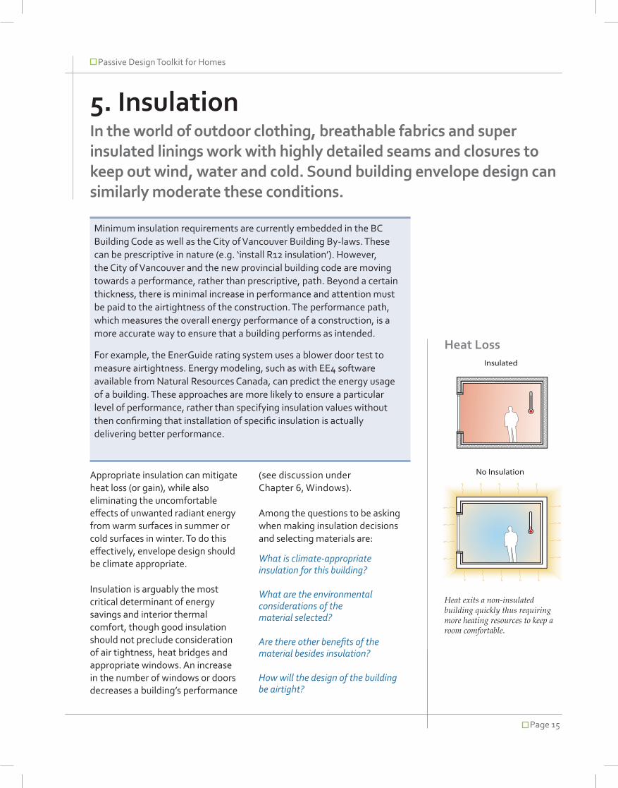
Heat Loss
Appropriate insulation can mitigate heat loss (or gain), while also eliminating the uncomfortable effects of unwanted radiant energy from warm surfaces in summer or cold surfaces in winter. To do this effectively, envelope design should be climate appropriate.
Insulation is arguably the most critical determinant of energy savings and interior thermal comfort, though good insulation should not preclude consideration of air tightness, heat bridges and appropriate windows. An increase in the number of windows or doors decreases a building’s performance
Minimum insulation requirements are currently embedded in the BC Building Code as well as the City of Vancouver Building By-laws. These can be prescriptive in nature (e.g. ‘install R12 insulation’). However, the City of Vancouver and the new provincial building code are moving towards a performance, rather than prescriptive, path. Beyond a certain thickness, there is minimal increase in performance and attention must be paid to the airtightness of the construction. The performance path, which measures the overall energy performance of a construction, is a more accurate way to ensure that a building performs as intended.
For example, the EnerGuide rating system uses a blower door test to measure airtightness. Energy modeling, such as with EE4 software available from Natural Resources Canada, can predict the energy usage of a building. These approaches are more likely to ensure a particular level of performance, rather than specifying insulation values without then confirming that installation of specific insulation is actually delivering better performance.
Insulated
No Insulation
Heat exits a non-insulated building quickly thus requiring more heating resources to keep a room comfortable.
(see discussion under Chapter 6, Windows).
Among the questions to be asking when making insulation decisions and selecting materials are:
What is climate-appropriate insulation for this building?
What are the environmental considerations of the material selected?
Are there other benefits of the material besides insulation?
How will the design of the building be airtight?

Passive Design Toolkit for Homes
Page 16
5.1 Insulation Materials
Over the lifespan of a building, insulation will always have a positive environmental impact by reducing operating energy. However, the ecological footprint of the material itself should also be taken into consideration. This is complicated to define because there are a lot of different factors to be considered. Insulation can also have a bearing on indoor environmental quality depending on the materials selected, and can have implications for airtightness.
Classification of insulation is not straightforward as there are several systems to differentiate between materials. Materials can be categorized as organic or inorganic; renewable or non-renewable; or they can be listed by consistency, such as foam, rigid, wool or loose.
Insulation materials can be categorized into organic or inorganic, renewable or non-renewable, or they can be listed by consistency, such as foam or rigid, wool or loose.
Examples of insulating materials (all available locally):
Conventional Insulating Materials
Fibreglass
Fibreglass in one of its two forms (loose or batts), remains the industry standard in North America. Most fibreglass insulation now contains some recycled content, and some manufacturers have replaced the traditional-but-toxic phenol formaldehyde binder with other more benign alternatives – or no binder is used at all.
Loose fill, a type of fibreglass insulation which is small and fluffy and blown into place, is associated with black mould and health hazards similar to those associated with asbestos such as lung disease. On the other hand, fibreglass
Thermal Resistance
The thermal resistances of insulation materials will contribute to indoor surface temperatures of a building’s exterior walls and thereby the internal thermal comfort. High thermal resistance indicates good insulating qualities. Resistance is in turn influenced by the temperature difference between inside and outside, the conductivity of the insulation used, and the thickness of this material.
Temperature difference is an external factor, while thickness and conductivity are determined by the choice of insulation material. Lower conductivity and greater thickness both reduce heat flow.
R-values are a measure of a material’s resistance to heat flow, and are therefore an indicator of a material’s insulation properties. On the other hand, U-values are a measure of the amount of heat that escapes a surface. In the case of windows, the glass does not act as an insulation material, and therefore measurement of R-value is not appropriate, and we use U-values instead.
R=1/U
The higher the R-value, the better insulation qualities displayed by the material. The lower the U-value, the better performance of a window against allowing heat or cold to pass through it.

Passive Design Toolkit for Homes
Page 17
Many aerogels are translucent – and can be used to insulate windows and skylights or create translucent walls.
batts are considered to have little or no negative impact on indoor environmental quality.
Spray applied foam
Sprayed foam insulation is used in some higher performance residential buildings. It allows for continuity of insulation as insulation is sprayed when in liquid form, and then expands to fill the cavity – including the smallest cracks. Performance is not as prone to installation errors.
Products range from those with a high content of toxic substances, to those that are water-blown and do not off-gas.
Rigid Polystyrene
This product displays fairly high R-Values (RSI-Values) and is durable as well as relatively affordable.
There are, however, issues with CFC’s and other hazardous substances that go into the production of polystyrene panels. Furthermore, this material is a derivative of crude oil, and therefore displays a large carbon footprint.
Some polystyrene products do not off-gas, and of the two main types of rigid polystyrene (extruded or XPS, and expanded or EPS) EPS is the more environmentally benign.
Aerogels
Aerogels are a form of frozen silica smoke with extremely small pores, making this material extremely durable and light with incredible insulation values. Many are also translucent – and can be used to insulate windows and skylights or create translucent walls.
However, this is a very new material and testing is indicating that silica foam has similar detrimental health effects to fibreglass and asbestos; microscopic particles can break off and lodge in skin or lungs. Use of aerogels is not very common.
Mineral Wool
In industrial and commercial construction, mineral wool remains popular for its fire resistance, though extraction and processing of mineral wool (a by product of steel processing) may still be an environmental concern.
Passive Design Toolkit for Homes
Page 18
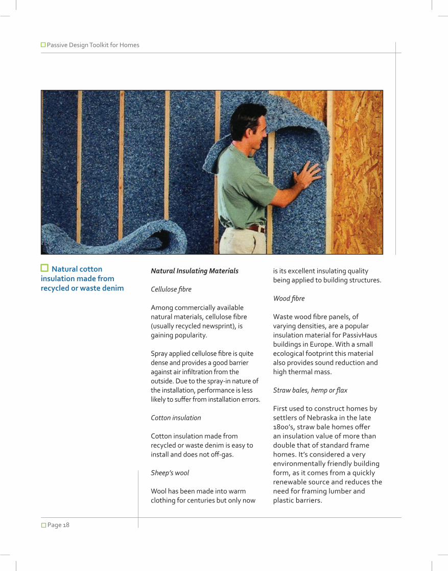
Natural cotton insulation made from recycled or waste denim
Natural Insulating Materials
Cellulose fibre
Among commercially available natural materials, cellulose fibre (usually recycled newsprint), is gaining popularity.
Spray applied cellulose fibre is quite dense and provides a good barrier against air infiltration from the outside. Due to the spray-in nature of the installation, performance is less likely to suffer from installation errors.
Cotton insulation
Cotton insulation made from recycled or waste denim is easy to install and does not off-gas.
Sheep’s wool
Wool has been made into warm clothing for centuries but only now
is its excellent insulating quality being applied to building structures.
Wood fibre
Waste wood fibre panels, of varying densities, are a popular insulation material for PassivHaus buildings in Europe. With a small ecological footprint this material also provides sound reduction and high thermal mass.
Straw bales, hemp or flax
First used to construct homes by settlers of Nebraska in the late 1800’s, straw bale homes offer an insulation value of more than double that of standard frame homes. It’s considered a very environmentally friendly building form, as it comes from a quickly renewable source and reduces the need for framing lumber and plastic barriers.

Passive Design Toolkit for Homes
Page 19
Tabl
e 2
– In
sula
tion
Com
pari
son
Char
t
Insu
lati
on
Mat
eria
lCo
mm
on A
pplic
atio
nEn
viro
nmen
tal I
mpa
ctIA
Q im
pact
Typi
cal
R V
alue
pe
r inc
h
Oth
er C
onsi
dera
tion
sCo
st
Effec
tiven
ess
($-$
$$$$
)Fib
reglas
s Batt
Typic
ally be
twee
n floo
r or c
eiling
jois
ts or
wall s
tuds
Some
bran
ds ha
ve up
to 40
% rec
ycled
conte
nt an
d hav
e elim
inated
use o
f toxic
bind
ers, i.
e. Fo
rmald
ehyd
e-free
Made
from
mater
ial wit
h abu
ndan
t sup
ply
If non
-toxic
bind
ers us
ed th
en
harm
less.
Re
spira
tor or
certifi
ed du
st ma
sk to
pro
tect th
e lun
gs an
d lon
g slee
ve
garm
ents
and g
loves
to pr
otect
the
skin
shou
ld be
worn
whe
n work
ing
with fi
bregla
ss
3.6Lo
w mo
isture
abso
rption
Fire r
esista
nt wit
h low
flame
sprea
d rati
ng
(non-f
aced
only)
Does
not a
bsorb
or re
tain m
oistur
eLit
tle or
no se
ttling
Ease
on in
stallat
ion (p
lacem
ent a
nd cu
tting
for irr
egula
r spa
ces)
Does
not a
ttract
insec
tsIns
ulatio
n valu
e dec
rease
s whe
n wet
$
Fibreg
lass b
lown
or po
ured
Typic
ally be
twee
n floo
r or c
eiling
jois
ts (ho
rizon
tally)
whe
re the
re wil
l be n
o traf
fic (i.
e. att
ic), c
an be
us
ed in
wall
studs
(vert
ically)
but
instal
lation
may
be re
stricte
d due
to
wall b
lockin
g, na
ils, ca
bles,
etc. In
ho
rizon
tal ap
plicati
ons it
is ex
cellen
t at
leavin
g no g
aps.
Will r
equir
e sma
ll hole
s to b
e blow
n int
o wall
caviti
es
Some
bran
ds ha
ve up
to 25
% rec
ycled
conte
nt an
d hav
e elim
inated
use o
f toxic
bind
ers, i.
e. Fo
rmald
ehyd
e-free
If non
-toxic
bind
ers us
ed th
en
harm
less.
Re
spira
tor or
certifi
ed du
st ma
sk to
pro
tect th
e lun
gs an
d lon
g slee
ve
garm
ents
and g
loves
to pr
otect
the
skin
shou
ld be
worn
whe
n work
ing
with fi
bregla
ss
2.9Lo
w mo
isture
abso
rption
Fire r
esista
nt wit
h low
flame
sprea
d rati
ngDo
es no
t abs
orb or
retai
n mois
ture
Little
or no
settlin
gBe
tter in
sulat
ion co
verag
e whe
n dea
ling w
ith
irregu
lar sp
aces
, ceili
ng pr
otrus
ions,
hard
to rea
ch sp
aces
, etc.
as it
create
s a bl
anke
t ov
er ev
erythi
ngRe
quire
s a pr
ofess
ional
to ins
tall
Must
ensu
re it d
oes n
ot blo
ck at
tic ve
nting
wh
en bl
own i
n
$$
Spray
Po
lyuret
hane
Fo
am
Can b
e use
d any
where
insu
lation
is
requir
ed, v
ertica
lly or
horiz
ontal
ly.Ve
ry go
od fo
r situ
ation
s whe
re ba
tt or
board
insu
lation
is ha
rd to
attac
h, i.e
. floo
r rim
joists,
lintel
s, etc
.Ca
n also
be ap
plied j
ust a
s a ba
se
layer
and t
hen t
oppe
d with
batt
insula
tion t
o sav
e cos
ts
Conta
ins a
minim
um of
5% re
cycle
d con
tent
Can b
e up t
o 33%
soy-b
ased
HCFC
blow
ing ag
ents
replac
ed w
ith H
FCs,
carbo
n dio
xide o
r wate
r and
do no
t harm
the o
zone
laye
rCa
n crea
te a f
air am
ount
of wa
ste (fa
ce sh
aving
s in
stud c
avity)
Not re
cycla
ble
Once
the s
pray h
as cu
red (g
enera
lly aft
er 24
hours
) the c
ompo
nents
are
inert a
nd do
not e
ffect
IAQ
7No
settlin
gCa
n be u
sed a
s an a
ir barr
ier bu
t not
a va
pour
barrie
rCa
n fill a
nd se
al tin
y crac
ksNo
t attra
ctive t
o ins
ects
Mixe
d and
insta
lled on
-site
by a
profes
siona
lMu
st be
prote
cted f
rom pr
olong
ed U
V ex
posu
re to
sunlig
htRe
quire
s cov
ering
with
a fire
resis
tant
mater
ial wh
en us
ed in
doors
$$$$
XPS (
extru
ded)
Polys
tyren
e Bo
ard
Confi
ned s
pace
s like
base
ments
, fou
ndati
on sla
bs, c
rawl sp
aces
or
exter
ior w
alls. M
ust b
e tigh
t fit to
av
oid ga
ps
May c
ontai
n som
e rec
ycled
conte
nt an
d can
be
recyc
led its
elf.
Uses
HCF
C as
blow
ing ag
ent
Made
from
petro
l chem
icals
Recy
clable
Brom
inated
flame
retar
dants
pres
ent
a grea
ter he
alth c
once
rn tha
n the
no
nbrom
inated
flame
retar
dants
us
ed in
polyis
ocya
nurat
e, sp
ray
polyu
retha
ne, a
nd ce
llulos
e ins
ulatio
n.
4.7 - 5
.0Mo
isture
resista
nt an
d suit
able
for be
low
grade
applic
ation
sMu
st be
prote
cted f
rom pr
olong
ed ex
posu
re to
UV or
solve
ntsIf j
oints
are se
aled c
an ac
t as a
n air b
arrier
Wi
th inc
reasin
g thic
knes
ses c
an ac
t as a
va
pour
barrie
rWh
en in
stalled
on an
inter
ior su
rface
mus
t be
cove
red w
ith a
fire re
sistan
t mate
rial
mech
anica
lly fas
tened
to th
e build
ing
struc
ture
$$$

Passive Design Toolkit for Homes
Page 20
Insu
lati
on
Mat
eria
lCo
mm
on A
pplic
atio
nEn
viro
nmen
tal I
mpa
ctIA
Q im
pact
Typi
cal
R V
alue
pe
r inc
h
Oth
er C
onsi
dera
tion
sCo
st
Effec
tiven
ess
($-$
$$$$
)EP
S (ex
pand
ed)
Polys
tyren
e Bo
ard
Confi
ned s
pace
s like
base
ments
, cra
wl sp
aces
or ex
terior
walls
. If
below
grad
e mus
t be c
oated
with
foi
l or p
lastic.
Mus
t be t
ight fi
t to
avoid
gaps
May c
ontai
n som
e rec
ycled
conte
nt an
d can
be
recyc
led its
elf.
Made
from
petro
l-che
mica
ls
Brom
inated
flame
retar
dants
pre
sent
a grea
ter he
alth c
once
rn tha
n the
nonb
romina
ted fla
me
retard
ants
used
in po
lyisoc
yanu
rate,
spray
polyu
retha
ne, a
nd ce
llulos
e ins
ulatio
n.
3.7 - 4
.0Mo
isture
resista
nt an
d suit
able
for be
low
grade
applic
ation
sMu
st be
prote
cted f
rom pr
olong
ed ex
posu
re to
UV or
some
solve
ntsIf j
oints
are se
aled c
an ac
t as a
n air b
arrier
Wi
th inc
reasin
g thic
knes
ses c
an ac
t as a
va
pour
barrie
rWh
en in
stalled
on an
inter
ior su
rface
mus
t be
cove
red w
ith a
firer re
sistan
t mate
rial
mech
anica
lly fas
tened
to th
e build
ing
struc
ture
$$$
Aero
gel
Not y
et rea
dy fo
r com
merci
al us
eTh
is tec
hnolo
gy is
still e
arly in
the p
roduc
tion
stage
so co
mpreh
ensiv
e ana
lysis o
f effe
cts is
not
yet a
vailab
le. So
me re
searc
h is g
oing i
nto us
e of
disca
rded c
orn hu
sks f
or ae
rogel
manu
factur
e.
Aerog
el du
st ca
n gen
erate
dry
skin,
eye i
rritati
on an
d res
pirato
ry int
eractio
ns.
> 140
Light
weigh
tHig
h com
press
ive st
rength
$$$$
$
Polyu
retha
ne an
d Po
lyiso
cyan
urate
Bo
ard
Confi
ned s
pace
s like
base
ments
, fou
ndati
on sla
bs, c
rawl sp
aces
or
exter
ior w
alls. M
ust b
e tigh
t fit to
av
oid ga
ps
Good
for lo
catio
ns w
here
a high
R-
value
is req
uired
in a
small
thi
ckne
ss
Some
bran
ds us
e soy
-base
d foa
ms m
ade f
rom
renew
able
vege
table
oils an
d rec
ycled
plas
ticsCa
n hav
e som
e rec
ycled
conte
nt.Mo
st bra
nds n
o lon
ger u
se fo
rmald
ehyd
e or
HCFC
as th
e blow
ing ag
ent
Not re
cycla
bleMa
de fro
m pe
trol ch
emica
ls
Board
s are
cured
and t
he
comp
onen
ts are
inert
and d
o not
effec
t IAQ
5.8 - 7
.2Us
ually
come
doub
le fac
ed w
ith fo
il and
so
metim
es bo
nded
with
an in
terior
or ex
terior
fin
ishing
mate
rial
Foil fa
ce ac
ts as
a rad
iant h
eat b
arrier
addin
g ab
out R
2 to
the in
sulat
ion as
semb
lyMu
st be
prote
cted f
rom pr
olong
ed ex
posu
re to
UV or
wate
rIf j
oints
are se
aled c
an ac
t as a
n air b
arrier
Ca
n act
as a
vapo
ur ba
rrier
Must
be co
vered
with
a fire
-resis
tant m
ateria
l
$$$
Mine
ral W
ool
(Slag
and R
ock
Wool)
Attics
, woo
d-fram
ed ro
ofs, w
alls,
floors
and a
round
chim
neys
Made
from
natur
al ba
salt o
r volc
anic r
ock a
nd sla
g (a
by-pr
oduc
t, con
tainin
g ine
rt mate
rials,
produ
ced
durin
g the
blas
t furna
ce sm
elting
proc
ess a
nd
other
steel
makin
g ope
ration
s, the
refore
post-
indus
trial re
cycle
d was
te up
to 70
%)Wh
en pr
operl
y insta
lled ca
n sav
e up t
o 100
0 tim
es th
e amo
unt o
f ene
rgy us
ed to
prod
uce i
tPr
oduc
t is re
cycla
bleEn
ergy in
tensiv
e to p
roduc
e but
less p
er R
value
tha
n fibre
glass
Scien
tific re
searc
h sho
ws m
ateria
l is s
afe to
man
ufactu
re, in
stall a
nd
use w
hen f
ollowin
g man
ufactu
rers
instru
ctions
. Onc
e ins
talled
no
signifi
cant
fibres
are r
eleas
ed.
Can b
e CFC
and H
CFC
free
Mine
ral w
ool m
ay co
ntain
up to
5 %
phen
ol-for
malde
hyde
by
weigh
t—mo
re tha
n mos
t fibre
glass
ins
ulatio
ns.
3.1No
n-com
bustib
le an
d can
with
stand
tem
perat
ures u
p to 1
000 º
CRe
pels m
oistur
eEx
cellen
t aco
ustics
barrie
rEa
se of
insta
llation
(plac
emen
t and
cuttin
g for
irreg
ular s
pace
s)
$$
Cellu
lose F
ibre
(blow
n or p
oured
)Ty
pically
betw
een fl
oor o
r ceili
ng
joists
(horiz
ontal
ly), c
an be
used
in
wall s
tuds (
vertic
ally) b
ut ins
tallat
ion
may b
e res
tricted
due t
o wall
blo
cking
, nails
, cab
les, e
tc.No
t to be
used
below
grad
eWi
ll req
uire s
mall h
oles t
o be b
lown
into w
all ca
vities
Up to
80%
recyc
led pa
per, 2
0% fir
e reta
rdant
chem
icals
Requ
ires u
p to 3
0 tim
es le
ss en
ergy t
o mak
e tha
n fib
reglas
s or m
ineral
woo
l insu
lation
Inhala
tion o
f dus
t duri
ng in
stallat
ionVO
C em
ission
s from
ing in
ks
(altho
ugh a
n inc
reasin
g num
ber o
f ne
wspri
nt are
using
vege
table
base
d ink
s.)All
ergen
ic rea
ctions
may
occu
r from
ink
s
3.6Re
quire
s prof
essio
nal in
stallat
ionVo
ids un
likely w
ith ca
reful
instal
lerAb
sorbs
mois
ture w
hich m
ay le
d to f
unga
l gro
wth
Comb
ustib
le as
fire r
etarda
nt ma
y not
be
cons
istent
and m
ay de
terior
ate ov
er tim
eCa
n sett
le up
to 20
% ov
er tim
e
$$

Passive Design Toolkit for Homes
Page 21
Insu
lati
on
Mat
eria
lCo
mm
on A
pplic
atio
nEn
viro
nmen
tal I
mpa
ctIA
Q im
pact
Typi
cal
R V
alue
pe
r inc
h
Oth
er C
onsi
dera
tion
sCo
st
Effec
tiven
ess
($-$
$$$$
)Co
tton B
attTy
pically
betw
een fl
oor o
r ceili
ng
joists
or wa
ll stud
sCo
tton i
s a na
tural,
rene
wable
reso
urce b
ut the
cro
p is w
ater in
tensiv
e, an
d can
invo
lve th
e use
of
pestic
ides o
r fertil
izers
which
contr
ibute
to so
il eros
ion. S
ome s
ource
s inclu
de sc
rap de
nim
gene
rated
durin
g den
im m
anufa
cturin
g givin
g it a
hig
h rec
ycled
conte
nt (70
%+)
Low
energ
y con
sump
tion i
n man
ufactu
ring
proce
ssPr
oduc
t can
be re
cycle
d
No fo
rmald
ehyd
e-bas
ed bi
nders
Sa
fe to
hand
le3.6
Fire r
esista
nt wit
h low
flame
sprea
d rati
ngLit
tle or
no se
ttling
Ease
on in
stallat
ion (p
lacem
ent a
nd cu
tting
for irr
egula
r spa
ces)
Good
perfo
rman
ce at
low
tempe
rature
sWi
ll abs
orb m
oistur
e
$$
Shee
p’s W
ool
Typic
ally be
twee
n floo
r or c
eiling
jois
ts or
wall s
tuds
Wool
is a na
tural
renew
able
resou
rce th
at is
treate
d with
a na
tural
rubbe
r and
borax
solut
ion
for fo
rming
into
rolls.
Borax
is a n
atural
ly occ
urring
no
n-vola
tile sa
lt tha
t is us
ed fo
r it’s p
est-re
pellen
t, fire
-retar
ding,
and m
ateria
l pres
ervati
on qu
alities
. A n
atural
latex
rubb
er is u
sed t
o allow
borax
to be
ap
plied t
o eac
h fibre
and i
ncrea
ses t
he m
emory
eff
ect o
f the w
ool so
that
it will e
xpan
d bac
k to
it’s na
tural
shap
e afte
r bein
g com
press
ed du
ring
instal
lation
.
Borax
is pra
ctically
non t
oxic t
o bir
ds, fi
sh, a
quati
c inve
rtebra
tes,
and r
elative
ly non
toxic
to be
nefic
ial
insec
ts.
3.8Go
od so
und a
bsorp
tion.
Natur
al bu
fferin
g eff
ect h
elps r
egula
te ind
oor te
mpera
tures
. Re
tains
thick
ness
redu
cing i
nsula
tion
efficie
ncy o
vertim
e. Wo
ol is a
lso a
natur
al fire
retar
dant,
safe
to ha
ndle,
rene
wable
and
recyc
lable.
$$
Wood
Fibre
Bo
ards
Suita
ble fo
r inter
nal u
se as
therm
al an
d aco
ustic
insula
tion o
n floo
rs,
walls
and c
eiling
s. Th
ey ca
n also
be
used
as ex
terna
l insu
lation
with
ren
der p
rotec
tion a
nd ca
n rec
eive
lime a
nd ea
rth ba
sed c
lays b
and
rende
rs.
Wood
fibre
board
s are
rigid
buildi
ng bo
ards m
ade
from
sawm
ill off c
uts th
at are
pulpe
d, so
aked
and
forme
d into
board
s. Th
e boa
rds ar
e the
n hea
ted
and c
ompre
ssed
to th
eir fin
al thi
ckne
ss. P
araffin
wa
x may
be us
ed as
the b
inding
agen
t.
Board
s do n
ot co
ntain
and g
lue
or wo
od pr
eserv
ers. N
on to
xic in
ma
nufac
ture,
use a
nd w
aste
dispo
sal
3.899
.5% w
aste
mater
ial, of
f cuts
from
sawm
ill ma
inly. V
ery go
od br
eatha
bility
includ
ing
hygro
scop
ic mois
ture c
ontro
l to pr
even
t mo
ulds a
nd im
prove
indo
or air
qualit
y. Us
es
abou
t 1/10
th the
energ
y per
tonne
of pr
oduc
t co
mpare
d to p
lastic
insula
tion b
oards
. Woo
d fib
re bo
ard in
sulat
ion pr
ovide
s the
rmal
mass
to
help
regula
te int
erior
tempe
rature
s.
$$$
Straw
Bales
Used
as in
fill in
wall a
ssem
blies
in po
st an
d bea
m co
nstru
ction o
r as
a loa
d bea
ring w
all as
semb
ly.
Straw
bales
are t
ypica
lly 18
or 24
inc
hes w
ide, d
epen
ding u
pon s
tack
orien
tation
.
Any t
ype o
f stra
w ca
n be u
sed,
whea
ts, oa
tes,
barle
y, etc
. The
bales
are m
ade f
rom th
e ag
ricult
ure w
aste
of the
harve
st, w
hich i
s ann
ually
renew
able
and i
n man
y part
s of th
e worl
d is
typica
lly bu
rned i
n the
field.
Straw
bales
are a
non-t
oxic p
roduc
t tha
t allow
s a gr
adua
l tran
sfer o
f air
throu
gh th
e wall,
bring
ing fre
sh ai
r into
your
living
envir
onme
nt, es
pecia
lly wh
en co
mbine
d with
a na
tural
plaste
r. Mo
st str
aw ba
le ho
uses
do no
t inc
orpora
te va
pour,
air o
r mois
ture
barrie
rs as
they
wan
t the n
atural
bre
athab
ility of
the w
all wh
ich fu
rther
reduc
es th
e num
ber o
f man
mad
e ch
emica
ls imp
actin
g the
indo
or air
qu
ality.
2.7Ex
cellen
t fire
resista
nce q
ualitie
s, a p
laster
ed
straw
bale
wall w
ill eas
ily pa
ss a
two-h
our
fire te
st. St
raw ba
les ho
uses
have
stoo
d the
test
of tim
e, so
me be
ing ol
der th
an 10
0 ye
ars. E
xcelle
nt so
und a
bsorp
tion a
nd ea
se
of bu
ilding
can r
educ
e con
struc
tion c
osts.
Re
quire
s large
overh
angs
for m
oistur
e pro
tectio
n in r
ainy c
limate
s
$$

Passive Design Toolkit for Homes
Page 22
5.2 Selecting Insulation Materials
Insulation can serve as more than just an energy barrier, providing fire resistance, humidity control, and noise reduction among other things. Many fibre-based materials, such as cellulose or wood fibre, are sensitive to water exposure – a common concern in Vancouver’s climate. On the other hand, these materials can also act to modify humidity levels, which is particularly relevant for structures which are meant to breathe, such as those which use straw bales.
Select materials by balancing their relative strengths and weaknesses against environmental impact considerations. Table 2 provides a comparison of common insulation materials and their applications.
Specific Heat Capacity
This term is used to compare the heat storage capacity per unit weight of different materials. Unlike thermal mass, heat capacity is not linearly related to weight; instead it quantifies the heat storage capacity of a building element or structure, rather than its ability to absorb and transmit that heat.
The thermal mass of a material or assembly is a combination of three properties:
Specific heat
Density
Thermal conductivity
Fire Resistance
The combustibility of insulation materials is also an important consideration, although deaths in fire situations are more commonly caused by the inhalation of smoke generated by combustion of the room contents rather than the building envelope materials. Products like rock wool or even cellulose and wood fibre perform better in fire situations than polyurethane or polystyrene based foams or fiberglass.
Another potential problem is the chimney effect caused by shrinking of insulation materials within the wall cavities. Gaps of 19mm or greater can lead to a convection loop, allowing flames to spread more quickly from storey to storey.
Noise Reduction
Noise reduction can be a valuable indirect benefit of thermal insulation. There are two characteristics materials need to display in order to have a positive influence on noise reduction: high mass and flexibility. Polystyrene or polyurethane, for example, display neither and therefore have nearly no influence on noise. Rock wool, fiberglass and cellulose fibres are soft and have a significant mass, so they can make a contribution to noise reduction. The densest insulating material is wood wool, which is a very efficient sound deadener.
The City of Vancouver Sound Smart Manual can be found at www.city.vancouver.bc.ca/engsvcs/projects/soundsmart/pdfs/NCM1.pdf. This document contains detailed information on sound control and the use of building materials and orientation to mitigate noise pollution.

Passive Design Toolkit for Homes
Page 23
5.3 Airtightness
It is imperative for a structure to have an airtight layer in order for insulation to be effective. There are several strategies for achieving a super tight building envelope.
Air Barriers
Up to 25 percent of the energy loss in a building is attributable to air leakage. This can be addressed quite easily in new construction with careful attention to draught sealing, as well as carefully designed air locks (such as double doors). Poor airtightness can also contribute to mould problems if warm humid air is allowed to seep into the structure. Renovations are more complicated, though an airtight layer has to be added to the existing structure.
An air barrier system should be continuous around all components of the building, with special attention given to walls, roof and the lowest floor. There must be proper continuity at intersections, such as the connection between floors, the joints between walls and
windows or doors, and the joint between walls and the roof.
External house wrap, polyethylene and airtight drywall are probably the most common techniques for creating an air barrier. Correct sealants and caulking can help to stop leaks and must be properly installed to ensure durability over time.
Vapour barriers
Vapour pressure is generally higher inside a building due to the moisture generated by the occupants and their activities. This will create an external flow of vapour towards the outside, where the pressure is lower. If the vapour is allowed to move through the assembly it can condense on the surface leading to dampness and ultimately to mould or rot.
A vapour barrier reduces the movement of the vapour through the building assembly so that condensation does not occur. There are several types of vapour retardants including polyethylene, foil or latex paint. Unlike an air barrier the continuity of the vapour barrier is not as crucial as it can still perform well even if gaps are present.
5.4 Thermal Bridges
A thermal bridge occurs where construction materials create a bridge between internal and external environments allowing a heat transfer to occur. Metal is highly conductive and therefore susceptible to thermal bridges but any material can contribute to this effect to some
+20°CInterior(warm)
+5°CExterior
(cold)
Interior Wall Finish
VapourBarrier
ThermalInsulation
ExteriorRainscreen
VentilatedSpace
Potential Condensation Zone
Predominant Heat and Moisture Di�usion Direction
Moisture Barrier
Up to 25 percent of the energy loss in a building is attributable to air leakage.

Passive Design Toolkit for Homes
Page 24
Insulation is one of the most critical elements in reducing energy consumption requirements by avoiding unnecessary loss of thermal energy. The choice of material can also have non-energy related positive impacts.
Synergies/Barriers:
When making decisions regarding insulation one should consider the whole building as a system and account for airtightness and vapour protection.
Energy modeling, for instance using HOT2000 software, can help to determine when increasing insulation in a certain part of the building will improve performance and when it can no longer make a difference.
It is important to remember that the main source of heat loss is through the windows, so it is essential to install high performance frames and to reduce thermal bridges in these areas.
Impact on Energy Efficiency:
Insulation lowers the need for heating and cooling, reducing overall energy consumption.
Insulation:
degree. Wherever possible, thermal bridges need to be avoided through the use of a thermal break.
Thermal breaks are literally breaks inserted into the component (for instance in the window frame), which separate the exterior and interior materials.
5.5 Assemblies
Cost: –
Energy modeling software
EE4: Software to assess the energy performance of your design and verify design compliance against the Model National Energy Code for Buildings (MNECB). Available from Natural Resources Canada at http://www.sbc.nrcan.gc.ca/software_and_tools/ee4_soft_e.asp.
Hot2000: A low rise residential energy analysis and design software available from Natural Resources Canada at http://www.sbc.nrcan.gc.ca/software_and_tools/hot2000_e.asp.
RETScreen: Evaluates the energy production and savings, costs, emission reductions, financial viability and risk for various Renewable Energy and Energy Efficient Technologies (RETs). Available from Natural Resources Canada at http://www.retscreen.net/ang/home.php.
cavity
drywall
masonry
drywall
EPS insulation
wood furring
exterior(ie stucco)
Cavity walls
Masonry walls
thermal break created by an insulation

Passive Design Toolkit for Homes
Page 25
6. Windows (Glazing)One of the most efficient ways to harness the power of the sun is through the use of suitable window technologies. Conventional residential buildings lose upwards of 50 percent of their heat through windows. At the same time, passive solar gain through windows is generally limited to just a few percent. In order to design windows that contribute to passive heating in the cooler winter months without an associated overheating risk in the summer, it is critical to balance location, size and thermal quality.
When making window decisions, consider the following:
How does window design address daylighting, views, ventilation?
How much heat loss will be attributable to the windows?
What is the payback for investing in high performance systems?
Are there other design considerations? (Overhangs, landscaping etc.)
6.1 Thermal Quality and Style of Window
The overall quality of a window is key to its performance and can be determined by the thermal quality of the glass and the frame. Further considerations are the solar heat gain coefficient of the glass and of the spacer material.
The style of window will also have an effect on its performance. Slider windows may be poorer air barriers as the sealing system is harder to design. Fixed windows are permanently sealed but do not offer the benefits of ventilation. Hinged windows use compression seals that are more sturdy than slider windows but may still wear out. Issues arise when worn out seals are not replaced.
Heat gain / heat loss
single paneU-Factor = 1.04
double paneU-Factor = 0.50
triple paneU-Factor = 0.15
photo: melis+melis+wimmers

Passive Design Toolkit for Homes
Page 26
What is a U Value?
U-value is measured by U = I/R
U-values for windows can refer to the centre of glass or edge of window ‘whole frame’ measurements.
The value will change with the size of the window because the ratio of window to frame will increase as the window gets bigger.
Most manufacturers provide the U value of the glass and the frame separately – proper analysis must assess the U value of the entire system.
Table 3Thermal Quality of Glass
Low-e windows: Double pane glass with a U-value ranging from 1.1-1.5 W/m²K and a solar heat gain coefficient of approximately 60%.
This type of window is more or less energy neutral when placed on the south side of a building, meaning solar gain is approximately the same as solar loss. If placed in any other location, this type of glass loses more energy than it gains. Therefore, it is recommended to avoid low-e windows when working with passive design especially in Vancouver which gets less than 2.5 hours of sun per day during the winter.
Super high performance windows: Triple pane glass with a U-value ranging from 0.5-0.7 W/m²K and a solar heat gain coefficient of 50-60%.
When used in cooperation with a super-insulated frame, these windows can facilitate solar heat gain. During cold or overcast days, or overnight, a window using this type of glass will lose less energy than it can capture during sunnier periods. Increasing the proportion of glass of this quality on the south side will encourage more passive solar gain.
A precondition for the glass to deliver the performance as per table 4 is a super-insulated frame. Installing high performance triple pane glass into a common frame would be inefficient. Even using a super-insulated frame, the frame is the weakest link delivering nearly no solar gain while also creating thermal
bridges. In other words, windows are always a source of energy loss.
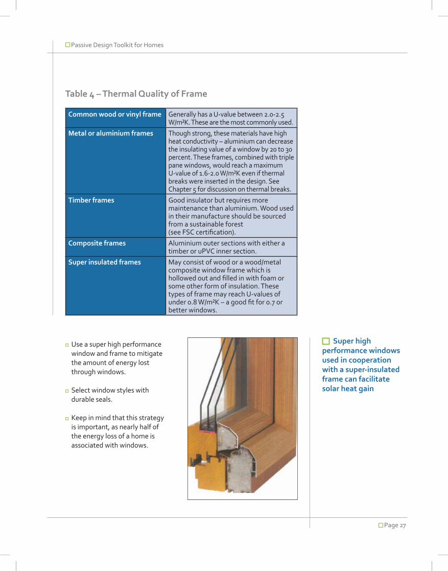
Passive Design Toolkit for Homes
Page 27
Table 4 – Thermal Quality of Frame
Common wood or vinyl frame Generally has a U-value between 2.0-2.5 W/m²K. These are the most commonly used.
Metal or aluminium frames Though strong, these materials have high heat conductivity – aluminium can decrease the insulating value of a window by 20 to 30 percent. These frames, combined with triple pane windows, would reach a maximum U-value of 1.6-2.0 W/m²K even if thermal breaks were inserted in the design. See Chapter 5 for discussion on thermal breaks.
Timber frames Good insulator but requires more maintenance than aluminium. Wood used in their manufacture should be sourced from a sustainable forest (see FSC certification).
Composite frames Aluminium outer sections with either a timber or uPVC inner section.
Super insulated frames May consist of wood or a wood/metal composite window frame which is hollowed out and filled in with foam or some other form of insulation. These types of frame may reach U-values of under 0.8 W/m²K – a good fit for 0.7 or better windows.
Use a super high performance window and frame to mitigate the amount of energy lost through windows.
Select window styles with durable seals.
Keep in mind that this strategy is important, as nearly half of the energy loss of a home is associated with windows.
Super high performance windows used in cooperation with a super-insulated frame can facilitate solar heat gain

Passive Design Toolkit for Homes
Page 28
6.2 Location and Size of Windows
For a complete discussion of appropriate locations for windows, see the discussion in Section 3.2.
It is also important to remember that, in addition to having the lowest insulation value as a component of the building envelope, windows are also a source for thermal bridges. Therefore, an appropriate number of windows will mitigate unnecessary heat loss or gain. As a general rule of thumb, windows should not exceed 2/3 of the envelope.
In fact, due to the nature of thermal bridges, the number of individual windows should also be kept to a minimum – one slightly larger window is more efficient that two windows even if they equal the same area of window.
Do not overglaze.
Minimize the number of windows.
6.3 Shading
Appropriate use of shading can prevent too much heat from entering a building by shading the glass from direct sunlight. This is particularly important for the south elevation during the warm summer months. Shading strategies can include using overhangs, eaves, louvres and sunshades to regulate solar access.
Properly size and position overhangs to reduce solar gain during the times of the year it is not required
Passive window shading
Curtains can be used to improve the performance of existing windows but are neither efficient nor effective as the solar heat gain is already inside the building envelope. Heavy curtains may reduce heat loss, but air movement will still encourage the warm air to escape. Blinds can work to reduce glare, but the are also not effective at blocking solar heat gain.
Exterior shading, such as automated blinds, are not truly passive as they consume energy, materials and resources in their manufacture. They also include working parts which are susceptible to failure.
Louvres offer non-mechanical exterior shading
Louvres are used for shading on this building in Heidelberg, Germany
Passive window shading
Overhang
Louvres
Sunshades
photo: Battersby Howat

Passive Design Toolkit for Homes
Page 29
Window strategies are one of the most effective methods to make use of solar gain and limit energy loss. Proper attention to windows and shading can ensure maximizing winter sun, while also preventing summer overheating.
Synergies/Barriers:
It is important to balance solar considerations of windows with natural daylighting and view considerations.
High performance windows can be expensive. Aim for the lowest U-value that is affordable and avoid overglazing.
Impact on Energy Efficiency:
Appropriate use of this strategy can greatly increase the energy efficiency of a building.
Windows: Cost:

Passive Design Toolkit for Homes
Page 30
photo: Hotson Bakker Boniface Haden

Passive Design Toolkit for Homes
Page 31
7. LightingDaylighting and access to natural sunlight are essential for living spaces, as this quality of light promotes occupant comfort. Good daylighting eliminates the need for artificial lighting, reducing energy consumption for this purpose.
7.1 Interior Layout and Windows
When making decisions about lighting it is important to consider that appropriate building layout and orientation can reduce the need for artificial lighting and thus improve occupant comfort. Building layout should respond to the path of the sun, providing a sufficient supply of natural daylight through windows. South facing windows provide lots of daylight, as well as solar gains, while windows facing the northern elevation can deliver diffused lighting with minimal solar gain.
Good passive design should situate windows in multiple directions in order to balance interior lighting requirements. With the appropriate strategy, the amount and quality of light can be varied according to the lighting requirements of each space; direct light for kitchens, offices and workshops, and reflected or diffused light for living rooms or bedrooms.
Use multiple window orientations for balanced lighting levels
Choose lighting schemes based on room function
For further discussion of layout and windows, see Sections 4 and 6
When designing a passive lighting strategy, here are some questions to ponder:
What is the primary function of this room and what type of light does it require?
When will the room be occupied (morning, afternoon, evening)?
What is the most appropriate style and placement for windows considering the path of the sun?
7.2 Skylights vs. Solar Tubes
Although skylights can bring in lots of natural daylight, they are also a source of heat loss in the winter and heat gain in the summer.
Solar tubes, on the other hand, are simpler to install and provide daylight without the associated heat gain and a minimal amount of heat loss. Solar tubes are lined with reflective material to reflect and diffuse light to isolated areas.
Use reflection techniques and solar tubes to funnel daylight into the house
7.3 Clerestory Windows
A clerestory wall is a high wall with a row of overhead windows that
Types of Daylighting
Light Shelf
Light Duct
Reflective Blinds
Solar Tube
Roof Monitors
Sky Light

Passive Design Toolkit for Homes
Page 32
Heat gain from artificial lighting fixtures
Less than 10% of the energy use of a standard incandescent bulb (e.g. 40W, 60W, 100W tungsten filament bulbs) is converted to visible light, with the rest ending up as heat energy. Using more energy efficient light bulbs will ensure energy is efficiently directed to deliver its assigned purpose, in this case artificial lighting.
Compact Fluorescent Lights (CFLs) are the most significant development in home lighting, lasting up to 13 times as long as incandescent bulbs and using about ¼ the amount of electricity. New and improved colour renditions give a warmer light than older CFL technology.
Tungsten-halogen lamps are a newer generation of incandescent lights that provide a bright, white light close to daylight quality. These are powerful high-voltage lamps best used for general illumination.
More energy-efficient, low-voltage halogen lights are ideal for accent lighting. These lamps can last as long as 2000 hours and save up to 60% of the electricity used with incandescent lights.
Automation techniques and smart technology also help to mitigate high energy use. Dimmer switches and motion detectors can automatically adjust to conditions based on a predetermined schedule.
Reduce the reliance on artificial light as much as possible
Increase illumination effectiveness by using light coloured sources
Use low wattage bulbs close to where they are needed
Use energy efficient bulbs instead of regular incandescents
Eliminate the unnecessary over-use of electricity with the use of dimmers, timers, motion sensors and cupboard contact switches
can allow in light. When clerestory windows are opened they can also act to cool the room by creating convection currents which circulate the air.
Position clerestory windows to face south, with eaves to block the hot summer sun
Types of Daylightingcontinued...
Atrium
Clerestory
External Reflectors

Passive Design Toolkit for Homes
Page 33
7.4 Paint as a Passive Lighting Strategy
The albedo of an object refers to its capacity to reflect light. Light coloured paints can make spaces look and feel brighter while also mitigating the heat island effect through reduced heat absorption.
In winter, when solar radiation is not as intense and solar gains are sought after, high albedo surfaces adjacent to the house can reflect solar radiation into the house, to be
absorbed by the internal thermal mass. This strategy also provides daylight into the interior, as well as increasing nighttime lighting levels.
Select appropriate surfaces to paint with light coloured paint or other high albedo material
Decide where light is required and balance with heat considerations
White painted windowsills can increase the amount of light into a room by reflecting outside light
Heat Island Effect
A heat island is an area, such as a city or industrial site, having consistently higher temperatures than surrounding areas because of a greater retention of heat by buildings, concrete, and asphalt. Causes of the “heat island effect” include dark surfaces that absorb more heat from the sun and lack of vegetation which could provide shade or cool the air.
Light coloured paints can make spaces look and feel brighter while also mitigating heat island effect.

Passive Design Toolkit for Homes
Page 34
Passive lighting implies maximizing the use of natural daylighting in order to reduce the reliance on artificial lighting fixtures, which can be costly and inefficient.
Synergies/Barriers:
Lighting strategies need to be balanced against solar heat gains.
Clerestories and solar tubes can be appropriate where privacy is necessary.
When choosing window styles for lighting remember to keep in mind other passive design best practices such as quality of windows and ventilation.
High gloss paint leads to acute brightness – to achieve passive lighting use matte paint to deliver a softer brightness.
Shade reflective surfaces with overhangs, trees or vegetation to mitigate unwanted heat gain in the summer.
Impact on Energy Efficiency:
Decreasing dependence on artificial lighting can help to curb energy consumption but natural light also contributes to higher occupant comfort. This strategy can be achieved with minimal extra associated costs.
Lighting: Cost: –

Passive Design Toolkit for Homes
Page 35
8. VentilationWhen there is a difference between outdoor and indoor temperature, ventilation can be accomplished by natural means. Strategically placed windows make use of prevailing winds to allow ventilation, bringing in fresh air while removing warm or stale air.Ventilation also has an impact on heating and cooling.
When considering ventilation strategies, it is helpful to consider the following questions:
How will the window contribute to occupant comfort?
Where should windows be located to achieve the desired impact?
8.1 Window Placement
The height and opening direction will affect the degree to which a window can take advantage of prevailing winds. Well thought out height and placement will direct air to where it is needed, while choosing windows that either open inward, outward or slide will affect the amount of air that can be captured.
Though ventilation has an impact on heating and cooling it also has stand alone merits to improve occupant comfort through appropriate access to fresh air.
Know the patterns of prevailing winds
Identify wind flow patterns around the building
Account for site elements such as
vegetation, hills or neighbouring buildings which will impact breezes
Orient fenestration and choose a style that catches and directs the wind as required
8.2 Stack Effect and Cross Ventilation
The following strategies can effectively encourage passive ventilation in a house.
Stack effect is achieved by placing some windows at lower levels (in the basement or at floor level), while others are placed at higher levels (at ceiling height or on the top floor). The lighter, warm air is displaced by the heavier, cool air entering the building, leading to natural ventilation. This warm/light interaction acts as a motor that keeps the air flowing, leading to what is called the ‘stack’ or ‘chimney’ effect. The greater the temperature difference, the stronger the air flow generated.
This kind of natural ventilation is appropriate for summer months, as it may also cool the interior space, reducing the need for electric fans or pumps traditionally used for cooling. This in turn can lead to lower energy consumption.
Stack Effect
Cross Ventilation

Passive Design Toolkit for Homes
Page 36
Heat Recovery Ventilator
Cross ventilation occurs between windows on different exterior wall elevations. Patio and screen doors are also effective for cross ventilation. In areas that experience unwanted solar gain, operable clerestory windows or ceiling/roof space vents can aid with ventilation and cooling (see Section 8.3).
Place windows where it is possible to achieve either stack effect or cross ventilation where required
Use appropriate window style to achieve desired effect
8.3 Window Style
The style and operability of a window can determine maximum levels of ventilation achievable. Louvres or hinged/pivoting units that open to at least 90 degrees can offer the greatest potential for ventilation. Awning, hopper or casement windows, opened by short winders, provide the least potential.
Maximize window opening and use hinged windows which can redirect breezes
8.4 Heat Recovery Ventilators
Heat recovery ventilators, or HRVs, are not strictly passive technology, but are recommended as part of a comprehensive passive design strategy. Ventilation which makes use of an HRV is more efficient, as the system reclaims waste energy from exhaust airflows. Incoming fresh air is then heated using this energy, recapturing 60 to 80 percent of the heat that would have been lost.
Passive design essentially encourages a very tight building envelope, while an HRV ensures a continuous supply of fresh air to this airtight interior. Filtration of the air through an HRV also stops dirt from entering the building, and can help to prevent development of mould.
Stale humid air exhaust
Fresh coolair intake
Incoming fresh air is warmed by outgoing
stale indoor air
Warm dry fresh air
Stale air intake

Passive Design Toolkit for Homes
Page 37
Natural ventilation eliminates the need for big mechanical systems and can provide occupant control over thermal comfort.
Synergies/Barriers:
Keep in mind that site conditions affect the ability to capture wind: allow for landscape, building shape and prevailing winds.
Security and wind driven rain should also be considered when deciding window or door placement.
HRVs require additional ducting to bring the exhaust air back to the HRV unit.
Exhaust from nearby cars and other external pollutants should be accounted for.
Unwanted heat loss can be reduced by preheating incoming air prior to distribution (using an HRV or other system).
Impact on Energy Efficiency:Using passive strategies for ventilation can leverage natural climatic conditions for little or no extra cost.
Ventilation:
Aim for a heat recovery rate greater than 75%, an leakage rate of less than 3%, and electricity efficiency of the unit greater than 0.4 Wh/m³ (0.04 Btu/ft³)
Provide ventilation controls that have user-operated settings for “low”, “normal” and “high”, and consider additional controls in kitchen and baths/toilets
Cost: –

Passive Design Toolkit for Homes
Page 38
photo: Battersby Howat

Passive Design Toolkit for Homes
Page 39
9. Thermal MassThermal mass is a measure of a material’s capacity to absorb heating or cooling energy. Materials such as concrete or bricks are highly dense and require a lot of energy to be heated or cooled. On the other hand, materials such as timber are less dense and do not need to absorb much energy for smaller changes in temperature. The more energy it takes to affect a temperature change of the material, the higher the thermal mass. The time it takes for the material to store and then release the heat energy is referred to as the thermal lag.
The thickness of a material impacts its energy storage capacity. For example, steel studs have a greater thermal mass than wood studs. The density of insulation materials differs and further affects thermal resistance values.
Table 5 Common Density Values
Material Density
Foams 15-40 kg/m3
Wood Fibre 160 kg/m3
Fibreglass 50-60 kg/m3
The simple application of thermal mass can work to passively heat or cool a building, as internal changes in temperature can be moderated to remove extremes of heat or cold. The reverse is also true; inappropriately located thermal mass can cause external temperatures to disproportionately affect internal thermal comfort.
Before increasing thermal mass to an area of a building, consider:
Will this location be best to exploit solar gain?
Can this location be shaded to avoid gain when it is not required?
9.1 How to Use Thermal Mass
How can this be applied to low rise wood framed construction ?
When using thermal mass it is critical to understand that it behaves differently than insulating material. Thermal mass is the ability of a material to store heat energy and then release it gradually. Insulating materials, on the other hand, prevent heat from passing through them. In fact, many high thermal mass materials display poor insulation characteristics.
The embodied energy in some thermal mass materials may also be taken into consideration. Some materials, such as concrete,
Feels Cold
Temp20°C
Feels Warm
Direct & Indirect Sunlight

Passive Design Toolkit for Homes
Page 40
require a lot of energy to manufacture and are inappropriate in relation to the actual energy savings they might deliver.
Mass situated on the south side of a building is most efficient for heating in Vancouver. The mass can absorb heat from the sun and then release this energy during the night. To avoid overheating, areas with high thermal mass should be shaded from this sun in the summer, or situated/landscaped to take advantage of cooling winds.
Thermal mass should generally be located on the ground floor, on the inside of a building, exposed to the indoor environment. Exposed
Radiant Heating
Thermal Mass
Sun enters room and heat is absorbed into flooring keeping the room temperature comfortable
Heat that was absorbed is released during the cool evening to add warmth to the room
In a room without thermal massing, heat from the sun is reflected into the room causing uncomfortable warmer temperatures
Structure with thermal massing:
Structure with no thermal massing:
In the cool evenings, a room without thermal massing will be uncomfortably cold
Radiant energy can be beneficial – this type of energy is emitted from a heat source and is different from tradition convection heating. This type of heating can penetrate all objects in its path and rather than heating the air, directly heats all objects in its path, including people.
This type of heating system can achieve the same level of thermal comfort using less energy, as heat is not lost to the air. Radiant systems include in-floor, ceiling panels or wall heating systems.
Radiant heat flooring vs. forced air heating
Even heating Uneven heating
Radiant heating Forced air heating
concrete floors or concrete block partition walls are very effective at absorbing thermal conditions (heat or cold).
Use the south side for thermal mass, but apply appropriate shading for summer months
Apply thermal mass on the ground level
9.2 Slab on grade construction
Slab on grade (SOG) is a very common method to create thermal mass. Generally about 4” thick, SOG should be insulated from the ground below to avoid losing heat in the winter.

Passive Design Toolkit for Homes
Page 41
Thermal mass can be effectively used to absorb solar heat in winter and radiate it back to the interior at night.
Synergies/Barriers:
Vancouver has minimal winter sun, so this strategy has limitations to significantly offset winter heating demands though it may be sufficient for shoulder season demands (spring and autumn).
Naturally occurring thermal mass areas can be used to reduce cooling demands more easily – keep high thermal mass elements shaded or away from solar gains.
Impact on Energy Efficiency:
Allows the house to heat and cool itself based on heat release from materials, lowering the need for additional heating.
Thermal Mass:
Phase Changing Materials
There is growing interest in the use of phase changing materials in construction. These are materials that can either emit or store heat energy as they change from a solid to a liquid or vice versa at certain temperatures. Therefore, these materials can be used, like thermal mass, to manage indoor thermal comfort.
Cost: –

Passive Design Toolkit for Homes
Page 42
photo: Chesterman Properties

Passive Design Toolkit for Homes
Page 43
10. DensityIn addition to building design, there are other elements that can impact the passive potential of a site. Density, measured in Vancouver as the ratio of building floor space to the site area, impacts energy consumption as well as the capacity of a building to be passively heated or cooled.
Density is regulated in most municipalities, including the City of Vancouver, by zoning by-laws based on development and planning policies. Though there is a process for rezoning applications, density cannot always be increased in every instance. Municipalities often have areas earmarked for greater density based on community plans, and the City of Vancouver has also introduced its EcoDensity policy, which aims to encourage density around transportation and amenity-rich nodes.
In general, large, single-family dwellings have a higher proportion of exterior wall surface and constitute lower density areas. These buildings require more energy for heating or cooling purposes, while ‘denser’, multi-unit buildings, townhouses or duplexes can take advantage of economies of scale and share or transfer heat between walls or floors thereby reducing overall energy demand. In fact, low-density developments comprising mainly single-family houses use nearly twice as much energy per square foot as multi-unit buildings in Canada.
Multi-unit buildings take advantage of economies of scale and share or transfer heat between floors and walls thereby reducing overall energy demand.
photo: Battersby Howat
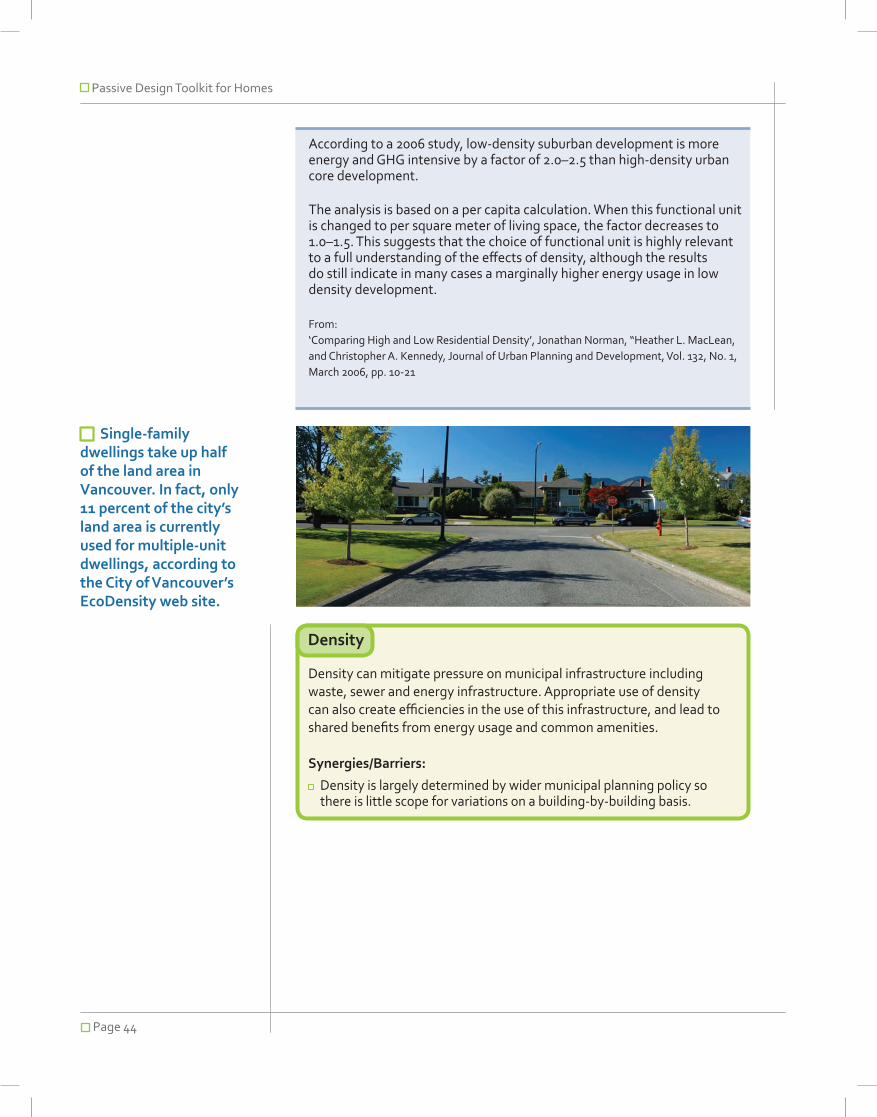
Passive Design Toolkit for Homes
Page 44
According to a 2006 study, low-density suburban development is more energy and GHG intensive by a factor of 2.0–2.5 than high-density urban core development.
The analysis is based on a per capita calculation. When this functional unit is changed to per square meter of living space, the factor decreases to 1.0–1.5. This suggests that the choice of functional unit is highly relevant to a full understanding of the effects of density, although the results do still indicate in many cases a marginally higher energy usage in low density development.
From: ‘Comparing High and Low Residential Density’, Jonathan Norman, “Heather L. MacLean, and Christopher A. Kennedy, Journal of Urban Planning and Development, Vol. 132, No. 1, March 2006, pp. 10-21
Density can mitigate pressure on municipal infrastructure including waste, sewer and energy infrastructure. Appropriate use of density can also create efficiencies in the use of this infrastructure, and lead to shared benefits from energy usage and common amenities.
Synergies/Barriers:
Density is largely determined by wider municipal planning policy so there is little scope for variations on a building-by-building basis.
Density
Single-family dwellings take up half of the land area in Vancouver. In fact, only 11 percent of the city’s land area is currently used for multiple-unit dwellings, according to the City of Vancouver’s EcoDensity web site.

Passive Design Toolkit for Homes
Page 45
11. Benefits of Passive Design
The strategies in this toolkit offer suggestions for harnessing the power of the sun and decreasing the energy consumption requirements of a typical home. As in other parts of the world, it seems reasonable to be able to achieve a reduction to just 15kWh/m2/year (heat/cool) if all strategies are used in combination. It is important to keep in mind that reducing consumption is the first step to designing energy efficient homes and approaching carbon neutrality (ie this should come before any discussion of on-site energy generation).
To get an idea of the possible impacts/benefits of passive design on energy consumption, consider the case study presented in the tables on the following page.
In short, a typical Vancouver single family home is 200 m2, with a 2x6 fully insulated stud wall and conventional windows with low-e windows. The average annual energy loss associated with a building of these specifications would equal roughly 16,000 kWh, or about 80 kWh / m2 / year. The passive solar energy harnessed by this home would be relatively small, at about 1,200 kWh per year, or roughly 7.5% of the amount of energy lost. Annual heating demand would average 64 kWh / m2 / year. photo: Hotson Bakker Boniface Haden

Passive Design Toolkit for Homes
Page 46
Table 6: Typical Vancouver Single Family Home
Size of Building
208 m2
Wall assembly
basement 2x6 fully insulated stud wall.Concrete with 2” XPS
Windows 30 m2 Conventional, low-e U Value=1.6 thereof 7.4 m2 on south side
Energy loss 18,000 kWh ≈ 80 kWh / m2/ year
Solar gain 1,200 kWh ≈ 6.6% of energy loss
Heating demand
69 kWh / m2 / year
Case Study
Table 6 shows the usual approach and the resulting energy consumption. The energy loss of 18,000 kWh is relatively high and the passive solar impact is with less than 7 percent extremely low.
The second example (Table 7) is based on a typical Vancouver single family home with a small rental unit in the basement. With a total floor area of 208 m2, the house was retrofitted during the last year.
This home is lined up against the typical Vancouver house (Table 6) with no recent upgrades. The resulting energy consumption and loss of 18,000 kWh is relatively high, but not an unreasonable assumption. The passive solar harnessed by this building is less than 7 percent of consumption, which is extremely low but again, not an unreasonable assumption with recent construction and design practices.
The main differences between the original house and the improved example in the case study are:
improved insulation thicknesses
improved air tightness
optimizing of heat bridges
improved thermal quality of windows
installation of heat recovery unit
With these improvements, total energy loss was reduced significantly despite the fact that it was possible to improve passive solar gain to only 10 percent of energy requirements, which is still very low performance.

Passive Design Toolkit for Homes
Page 47
Table 7: Better Vancouver Single Family Home
Table 8: Passive Vancouver Single Family Home
Size of Building
208 m2
Wall assembly
basement 2x6 fully insulated stud wall plus 3.5” exterior insulation Concrete with 6” XPS
Windows Ventilation with heat recovery 45 m2 Triple pane and insulated frame U Value = 0.78 thereof 21.5 m2 on south side 82% (air tightness @ 50Pa 0.6/h)
Energy loss
8,400 kWh ≈ 40 kwh/ m2/ year
Solar gain 3,200 kWh ≈ 38% of energy loss
Heating demand
15 kWh / m2 / year (PassivHaus standard)
Size of Building
208 m2
Wall assembly
basement 2x6 fully insulated stud wall plus 2” exterior insulation. Concrete with 3” XPS
Windows Ventilation with heat recovery 37 m2 Triple pane and insulated frame U Value = 0.78 thereof 7.4 m2 on south side 82% (air tightness @ 50Pa 0.77/h)
Energy loss
9,500 kWh ≈ 46 kWh / m2/ year
Solar gain 1,000 kWh ≈ 10.5% of energy loss
Heating demand
29 kWh / m2 / year
For comparison, the third example (Table 8) offers an estimate of the possible performance associated with a truly passively designed home. In this third instance, improvements would include:
further increases to insulation
window placement based on building orientation
Allowing the windows to be distributed according to solar gain potential increases the solar energy the building harnesses to 35 percent. By placing a larger proportion of windows on the southern elevation and less on the northern elevation, the passive design features of this building improve its performance nearly fivefold over the first example.

Passive Design Toolkit for Homes
Page 48
BibliographyDiamond, R. 1995. “Energy savings rise high in multifamily buildings.” Home Energy Magazine
McMullen, R. 2002. Environmental science in building, Palgrave, New York.
Norman, J., H. MacLean & C. Kennedy. 2006. Comparing High and Low Residential Density: Life-Cycle Analysis of Energy Use and Greenhouse Gas Emissions, Journal Of Urban Planning And Development / March 2006
OEE NRCan 2006. Energy Use Data Handbook 1990 and 1998 to 2004
Light House Sustainable Building Centre. Cost assessment of a bundle of green measures for new Part 9 buildings in the City of Vancouver. 2008: City of Vancouver
Schaeffer, J. 2008. Solar Living Source Book, New Society Publishers, BC.
Pearson, D. 1998. The New Natural House Book. Fireside, NY.
Roaf, S. 2007. Ecohouse. Architectural Press, Oxford UK
Kachadorian, J. 1997. The Passive Solar House, Chelsea Green Publishing Company, Vermont, USA.
Natural Resources Canada and CMHC. Tap the sun, Passive Solar Techniques and Home Designs.

Passive Design Toolkit for Homes
Page 49
Bibliography i. City of Vancouver Policy ContextThe City of Vancouver has a reputation as a leader in sustainable urban development.
This toolkit offers practices to encourage and support the use of passive design in Vancouver.
Green Homes Program
While developing passive design strategies, it is important to keep in mind the progress the City has already made in promoting green building. For Part 9 Buildings (low-rise wood frame residential), the City has adopted the Green Homes Program.
This program sets out higher standards for all new Part 9 buildings, including:
1. Building Envelope Performance:i. Windows must have
maximum U-Value of 2
2. Energy Efficiency:i. At least 40% of hard-wired
lighting should not accept incandescent light bulbs
ii. Display meters should be installed that can calculate and display consumption data
iii. Hot water tanks should have insulation with a minimum RSI value of 1.76

Passive Design Toolkit for Homes
Page 50
Part 3 Buildings are defined as structures over 3 storeys or greater than 600 m2
iv. Hot water tank piping should have 3 metres of insulation with a minimum RSI value of 0.35
v. Gas fireplaces shall have electric ignition
3. Other:i. Toilets shall be
dual-flush designii. Each suite shall have a
Heat Recovery Ventilatoriii. An EnerGuide Audit is
required at Occupancy Permit
Part 3 Buildings
The City is implementing several actions in line with their Green Building Strategy (as above) and recently enacted policies directed at energy efficiency and GHG reductions:
1. Improve and streamline enforcement of the energy utilization within the building law
2. Adopt ASHRAE 90.1 2007 as new Energy Utilization By-law
3. Decrease overall building energy use requirements by 12-15% beyond ASHRAE 90.1 2001 to meet Natural Resources Canada (NRCan) Commercial Building Incentive Program (CBIP) requirements
EcoDensity
The City has also implemented the EcoDensity policy, consisting of 16 actions. These actions apply only where there is a rezoning sought for a development.
1. All applicable buildings to be either LEED Silver with a minimum 3 optimize energy points, 1 water efficiency point and 1 stormwater management point or BuiltGreen BC Gold with an EnerGuide 80 rating
2. In addition, sites over two acres will require:
a. Business case analysis for viability of district energy systems
b. Layout and orientation which will reduce energy needs, facilitate passive energy solutions, incorporate urban agriculture and replicate natural systems
c. A sustainable transportation demand management strategy which includes requisite infrastructure
d. A sustainable rainwater management plan
e. A solid waste diversion strategyf. A range of housing unit
types and tenures to enhance affordability
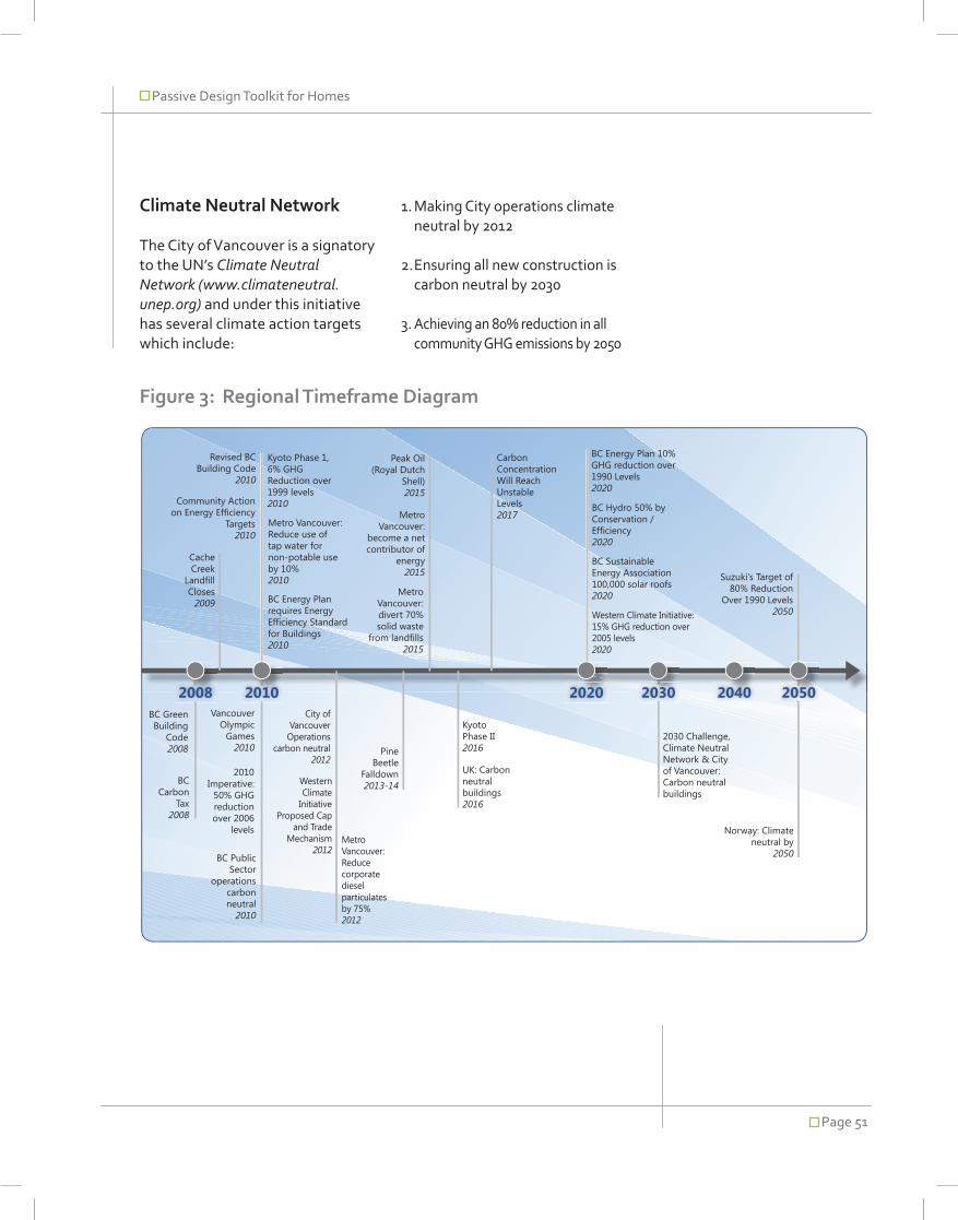
Passive Design Toolkit for Homes
Page 51
Climate Neutral Network
The City of Vancouver is a signatory to the UN’s Climate Neutral Network (www.climateneutral.unep.org) and under this initiative has several climate action targets which include:
Figure 3: Regional Timeframe Diagram
1. Making City operations climate neutral by 2012
2. Ensuring all new construction is carbon neutral by 2030
3. Achieving an 80% reduction in all community GHG emissions by 2050
2008 2010 2020 2030 2040 2050
Cache Creek
Landfi ll Closes2009
Vancouver Olympic
Games2010
BC Green Building
Code2008
BC Energy Plan requires Energy Effi ciency Standard for Buildings2010
2010 Imperative:
50% GHG reduction over 2006
levels
Metro Vancouver: Reduce use of tap water for non-potable use by 10%2010
Pine Beetle
Falldown2013-14
Peak Oil(Royal Dutch
Shell)2015
KyotoPhase II2016
2030 Challenge, Climate Neutral Network & City of Vancouver: Carbon neutral buildings
Carbon Concentration Will Reach Unstable Levels2017
BC Energy Plan 10% GHG reduction over 1990 Levels2020
Suzuki’s Target of 80% Reduction
Over 1990 Levels 2050
BC Hydro 50% by Conservation / Effi ciency2020
BC Carbon
Tax2008
BC Public Sector
operations carbon neutral2010
Kyoto Phase 1,6% GHG Reduction over 1999 levels2010
00000888 00111000
Revised BC Building Code
2010
Community Action on Energy Effi ciency
Targets2010
City of Vancouver
Operations carbon neutral
2012
Western Climate
Initiative Proposed Cap
and Trade Mechanism
2012 Metro Vancouver: Reduce corporate diesel particulates by 75%2012
Metro Vancouver:
become a net contributor of
energy2015
Metro Vancouver: divert 70% solid waste
from landfi lls 2015
UK: Carbon neutral buildings2016
BC Sustainable Energy Association 100,000 solar roofs2020
Western Climate Initiative: 15% GHG reduction over 2005 levels2020
Norway: Climate neutral by
2050

Passive Design Toolkit for Homes
Page 52
ii. Acronyms and terms used in this report Albedo The ability for an object to diffuse and reflect light from the sun. Light
coloured materials and paint have a high-albedo effect.ASHRAE American Society of Heating, Refrigeration and Air-Conditioning Engineers.
ASHRAE publishes standards and guidelines relating to HVAC systems (heating, ventilation and air conditioning) and many are referenced in local building codes.
Building Envelope The roof, walls, windows, floors and internal walls of a buildingCFL Compact Fluorescent LightsEnerGuide EnerGuide is the official Government of Canada mark associated with
the labeling and rating of the energy consumption or energy efficiency of specific products, including homes. Homes are rated on a scale of 0-100. A rating level of 100 represents a house that is airtight, well insulated and sufficiently ventilated and requires no purchased energy.
Floor space Floor space as used in this toolkit refers simply to the internal floor area bounded by the building envelope. However the method of measuring floor space precisely varies depending on the context-for example the Vancouver Building Bylaw contains a detailed description of the method of measurement of floor space for the purpose of submission for a Development or Building Permit and should be referred to for this purpose.
GHG Emissions Green House Gas EmissionsHeat Island Effect The term heat island refers to urban air and surface temperatures that are
higher than in rural areas due to the displacement of trees, increased waste heat from vehicles, and warm air which is trapped between tall buildings.
HRV Heat Recovery VentilatorIndoor Air Quality (IAQ) Indoor Air Quality (IAQ) refers to the composition of interior air, which
has an impact on the health and comfort of building occupants. IAQ is affected by microbial contaminants (mould or bacteria), chemicals (such as carbon monoxide or radon), allergens, or any other pollutant that effects occupants.
LEED® Leadership in Energy and Environmental Design green building rating system
Mechanical Systems Conventional systems that use fans and pumps to heat, ventilate and condition the air.
PassivHaus PassivHaus is a rigorous European home design standard developed in Austria and Germany, which regulates input energy to a maximum 15 kWh / m2 / year – about one tenth of that in a typical new 200 m2 Canadian house.
Solar Gain (also known as solar heat gain or passive solar gain) refers to the increase in temperature in a space, object or structure that results from solar radiation. The amount of solar gain increases with the strength of the sun, and with the ability of any intervening material to transmit or resist the radiation. In the context of passive solar building design, the aim of the designer is normally to maximise solar gain within the building in the winter (to reduce space heating demand), and to control it in summer (to minimize cooling requirements).

Passive Design Toolkit for Homes
Page 53
Thermal Bridges A thermal bridge is any part of a construction through which heat can travel faster and with less resistance than other parts.
Thermal Comfort Thermal comfort is defined by ASHRAE as human satisfaction with the surrounding environment, formalized in ASHRAE Standard 55. The sensations of hot and cold are not dependent on temperature alone; radiant temperature, air movement, relative humidity, activity levels and clothing levels all impact thermal comfort.
Thermal Mass Thermal mass is the ability of a material to store heat. Thermal mass can be incorporated into a building as part of the walls and floor. High thermal mass materials include: brick, solid concrete, stone or earth.
