parts replacement(v100r006c01 02)
TRANSCRIPT

OptiX OSN 8800/6800/3800V100R006C01
Parts Replacement
Issue 02
Date 2011-10-31
HUAWEI TECHNOLOGIES CO., LTD.

Copyright © Huawei Technologies Co., Ltd. 2011. All rights reserved.No part of this document may be reproduced or transmitted in any form or by any means without prior writtenconsent of Huawei Technologies Co., Ltd. Trademarks and Permissions
and other Huawei trademarks are trademarks of Huawei Technologies Co., Ltd.All other trademarks and trade names mentioned in this document are the property of their respective holders. NoticeThe purchased products, services and features are stipulated by the contract made between Huawei and thecustomer. All or part of the products, services and features described in this document may not be within thepurchase scope or the usage scope. Unless otherwise specified in the contract, all statements, information,and recommendations in this document are provided "AS IS" without warranties, guarantees or representationsof any kind, either express or implied.
The information in this document is subject to change without notice. Every effort has been made in thepreparation of this document to ensure accuracy of the contents, but all statements, information, andrecommendations in this document do not constitute the warranty of any kind, express or implied.
Huawei Technologies Co., Ltd.Address: Huawei Industrial Base
Bantian, LonggangShenzhen 518129People's Republic of China
Website: http://www.huawei.com
Email: [email protected]
Issue 02 (2011-10-31) Huawei Proprietary and ConfidentialCopyright © Huawei Technologies Co., Ltd.
i

About This Document
Related VersionsThe following table lists the product versions related to this document.
Product Name Version
OptiX OSN 8800 V100R006C01
OptiX OSN 6800 V100R006C01
OptiX OSN 3800 V100R006C01
iManager U2000 V100R005C00
iManager U2000 Web LCT V100R005C00
Intended AudienceThis document guides you how to replace parts.
This document is intended for field maintenance engineers.
Symbol ConventionsThe symbols that may be found in this document are defined as follows.
Symbol Description
DANGERIndicates a hazard with a high level of risk, which, if notavoided, will result in death or serious injury.
WARNINGIndicates a hazard with a medium or low level of risk, whichif not avoided, could result in minor or moderate injury.
OptiX OSN 8800/6800/3800Parts Replacement About This Document
Issue 02 (2011-10-31) Huawei Proprietary and ConfidentialCopyright © Huawei Technologies Co., Ltd.
ii

Symbol Description
CAUTIONIndicates a potentially hazardous situation, which if notavoided, could result in equipment damage, data loss,performance degradation, or unexpected results.
TIP Indicates a tip that may help you solve a problem or savetime.
NOTE Provides additional information to emphasize or supplementimportant points of the main text.
GUI ConventionsThe GUI conventions that may be found in this document are defined as follows.
Convention Description
Boldface Buttons, menus, parameters, tabs, window, and dialog titlesare in boldface. For example, click OK.
> Multi-level menus are in boldface and separated by the ">"signs. For example, choose File > Create > Folder.
Change HistoryUpdates between document issues are cumulative. Therefore, the latest document issue containsall updates made in previous issues.
Updates in Issue 02 (2011-10-31) Based on Product VersionV100R006C01
Update Description
4 Replacing theSCC Board withOne of the SamePCB Version
Section "Replacing the SCC Board" is renamed as "Replacing the SCCBoard with One of the Same PCB Version".The operation of clearing the databases on the SCC board is added to 4.4Replacing the SCC Board in a Slave Subrack.Some bugs are fixed.
5 Replacing theTN16XCHBoard
Some bugs are fixed.
OptiX OSN 8800/6800/3800Parts Replacement About This Document
Issue 02 (2011-10-31) Huawei Proprietary and ConfidentialCopyright © Huawei Technologies Co., Ltd.
iii

Update Description
6 Replacing theSCC Board withOne of aDifferent PCBVersion
Section "Upgrading Board Version of SCC Boards" is renamed as"Replacing the SCC Board with One of a Different PCB Version".The operation of clearing the databases on the SCC board is added to 6.3Replacing the SCC Board in a Slave Subrack.Some bugs are fixed.
7 Replacing theCross-ConnectBoard
Some bugs are fixed.
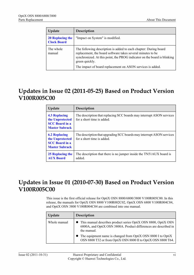
20 Replacing theClock Board
"Impact on System" is modified.
24 Replacing theDAS1 Board
Section "Replacing the DAS1 Board" is added.
The wholemanual
The following description is added to each chapter: During boardreplacement, the board software takes several minutes to besynchronized. At this point, the PROG indicator on the board is blinkinggreen quickly.The impact of board replacement on ASON services is added.
Updates in Issue 01 (2011-07-30) Based on Product VersionV100R006C01
Update Description
4 Replacing theSCC Board withOne of the SamePCB Version
The methods of replacing the TN16SCC board are added.
10 Replacing thePID Board
Section "Replacing the PID Board" is added.
Updates in Issue 03 (2011-09-15) Based on Product VersionV100R006C00
Update Description
5 Replacing theTN16XCHBoard
Some bugs are fixed.
OptiX OSN 8800/6800/3800Parts Replacement About This Document
Issue 02 (2011-10-31) Huawei Proprietary and ConfidentialCopyright © Huawei Technologies Co., Ltd.
iv

Updates in Issue 02 (2011-04-15) Based on Product VersionV100R006C00
The update of contents is described as follows:
Some bugs in the manual are fixed.
Updates in Issue 01 (2010-12-31) Based on Product VersionV100R006C00
This issue is the first official release for OptiX OSN 8800/6800/3800 V100R006C00.
Update Description
5 Replacing theTN16XCHBoard
Section "Replacing the TN16XCH Board" is added.
29 Replacing theEFI Board
The methods of setting the DIP switch on the TN16EFI board are added.
30 Replacing thePIU Board
The power cable connection diagram is added for the TN16PIU board.
Updates in Issue 03 (2011-08-30) Based on Product VersionV100R005C00
Update Description
4 Replacing theSCC Board withOne of the SamePCB Version
Section "Replacing the SCC Board" is renamed as "Replacing the SCCBoard with One of the Same PCB Version".The operation of clearing the databases on the SCC board is added to 4.4Replacing the SCC Board in a Slave Subrack.Some bugs are fixed.
6 Replacing theSCC Board withOne of aDifferent PCBVersion
Section "Upgrading Board Version of SCC Boards" is renamed as"Replacing the SCC Board with One of a Different PCB Version".The operation of clearing the databases on the SCC board is added to 6.3Replacing the SCC Board in a Slave Subrack.Some bugs are fixed.
OptiX OSN 8800/6800/3800Parts Replacement About This Document
Issue 02 (2011-10-31) Huawei Proprietary and ConfidentialCopyright © Huawei Technologies Co., Ltd.
v
Update Description
20 Replacing theClock Board
"Impact on System" is modified.
The wholemanual
The following description is added to each chapter: During boardreplacement, the board software takes several minutes to besynchronized. At this point, the PROG indicator on the board is blinkinggreen quickly.The impact of board replacement on ASON services is added.
Updates in Issue 02 (2011-05-25) Based on Product VersionV100R005C00
Update Description
4.3 Replacingthe UnprotectedSCC Board in aMaster Subrack
The description that replacing SCC boards may interrupt ASON servicesfor a short time is added.
6.2 Replacingthe UnprotectedSCC Board in aMaster Subrack
The description that upgrading SCC boards may interrupt ASON servicesfor a short time is added.
25 Replacing theAUX Board
The description that there is no jumper inside the TN51AUX board isadded.
Updates in Issue 01 (2010-07-30) Based on Product VersionV100R005C00
This issue is the first official release for OptiX OSN 8800/6800/3800 V100R005C00. In thisrelease, the manuals for OptiX OSN 8800 V100R002C02, OptiX OSN 6800 V100R004C04,and OptiX OSN 3800 V100R004C04 are combined into one manual.
Update Description
Whole manual l This manual describes product series OptiX OSN 8800, OptiX OSN6800A, and OptiX OSN 3800A. Product differences are described inthe manual.
l The equipment name is changed from OptiX OSN 8800 I to OptiXOSN 8800 T32 or from OptiX OSN 8800 II to OptiX OSN 8800 T64.
OptiX OSN 8800/6800/3800Parts Replacement About This Document
Issue 02 (2011-10-31) Huawei Proprietary and ConfidentialCopyright © Huawei Technologies Co., Ltd.
vi

Update Description
4 Replacing theSCC Board withOne of the SamePCB Version
Setting the Battery Jumper on the SCC is an independent section.
6 Replacing theSCC Board withOne of aDifferent PCBVersion
Section "Upgrading Board Version of SCC Boards" is added.
OptiX OSN 8800/6800/3800Parts Replacement About This Document
Issue 02 (2011-10-31) Huawei Proprietary and ConfidentialCopyright © Huawei Technologies Co., Ltd.
vii

Contents
About This Document.....................................................................................................................ii
1 Precautions......................................................................................................................................11.1 Specifications and Versions................................................................................................................................41.2 Laser...................................................................................................................................................................41.3 Short Circuit.......................................................................................................................................................61.4 ESD.....................................................................................................................................................................61.5 Working on Equipment with Power Applied.....................................................................................................81.6 Alarm and Safety Symbols.................................................................................................................................81.7 Correct Board Inserting and Removing..............................................................................................................9
2 Component Category..................................................................................................................10
3 Tools and Instruments................................................................................................................19
4 Replacing the SCC Board with One of the Same PCB Version..........................................204.1 Setting the Battery Jumper on the SCC............................................................................................................224.2 Replacing the Protected SCC Board in a Master Subrack................................................................................274.3 Replacing the Unprotected SCC Board in a Master Subrack...........................................................................37
4.3.1 Replacing the SCC Board with the Database Backed Up to the NMS (NE Is Unreachable)..................384.3.2 Replacing the SCC Board with the Database Backed Up to a CF Card (NE Is Unreachable)................514.3.3 Replacing the SCC Board After Configuring SCC 1+1 Protection.........................................................624.3.4 Replacing the SCC Board with the Database Backed Up to the NMS (NE Is Reachable).....................724.3.5 Replacing the SCC Board with the Database Backed Up to a CF Card (NE Is Reachable)...................86
4.4 Replacing the SCC Board in a Slave Subrack..................................................................................................98
5 Replacing the TN16XCH Board..............................................................................................1075.1 Setting the Battery Jumper on the TN16XCH Board.....................................................................................1085.2 Replacing the TN16XCH Board in a Master Subrack...................................................................................1095.3 Replacing the TN16XCH Board in a Slave Subrack......................................................................................113
6 Replacing the SCC Board with One of a Different PCB Version....................................1166.1 Replacing the Protected SCC Board in a Master Subrack..............................................................................1176.2 Replacing the Unprotected SCC Board in a Master Subrack.........................................................................124
6.2.1 Replacing the SCC Board with the Database Backed Up to the NMS..................................................1246.2.2 Replacing the SCC Board with the Database Backed Up to a CF Card................................................1366.2.3 Replacing the SCC Board After Configuring SCC 1+1 Protection.......................................................148
OptiX OSN 8800/6800/3800Parts Replacement Contents
Issue 02 (2011-10-31) Huawei Proprietary and ConfidentialCopyright © Huawei Technologies Co., Ltd.
viii

6.3 Replacing the SCC Board in a Slave Subrack................................................................................................154
7 Replacing the Cross-Connect Board...................................................................................... 1627.1 Under Board 1+1 Protection...........................................................................................................................1637.2 Under No Protection.......................................................................................................................................164
8 Replacing the Optical Transponder Board...........................................................................1668.1 Under Client 1+1 Protection...........................................................................................................................1678.2 Under SNCP Protection..................................................................................................................................1718.3 Under OWSP Protection.................................................................................................................................1768.4 Under No Protection.......................................................................................................................................179
9 Replacing the Tributary and Line Board.............................................................................. 1839.1 Under Client 1+1 Protection...........................................................................................................................1859.2 Under SNCP Protection..................................................................................................................................1939.3 Under ODUk SPRing Protection....................................................................................................................1989.4 Under DBPS Protection..................................................................................................................................2029.5 Under DLAG Protection.................................................................................................................................2079.6 Under Board-Level Protection........................................................................................................................2109.7 Under No Protection.......................................................................................................................................214
10 Replacing the PID Board........................................................................................................21810.1 Under ODUk SNCP Protection....................................................................................................................21910.2 Under No Protection.....................................................................................................................................227
11 Replacing the SDH Board......................................................................................................23211.1 Under Protection...........................................................................................................................................23311.2 Under No Protection.....................................................................................................................................234
12 Replacing the BPA Board.......................................................................................................236
13 Replacing the EGSH Board................................................................................................... 24013.1 Under Protection...........................................................................................................................................24113.2 Under No Protection.....................................................................................................................................242
14 Replacing the Optical Multiplexer and Demultiplexer Board.......................................244
15 Replacing the Optical Add and Drop Multiplexing Board.............................................247
16 Replacing the Optical Amplifier Board..............................................................................250
17 Replacing the Raman Amplifier Board...............................................................................253
18 Replacing the Variable Optical Attenuator Board............................................................256
19 Replacing the Optical Supervisory Channel Board..........................................................259
20 Replacing the Clock Board.................................................................................................... 262
21 Replacing the Optical Protection Board..............................................................................264
22 Replacing the Spectrum Analyzer Board............................................................................267
OptiX OSN 8800/6800/3800Parts Replacement Contents
Issue 02 (2011-10-31) Huawei Proprietary and ConfidentialCopyright © Huawei Technologies Co., Ltd.
ix

23 Replacing the Optical Power and Dispersion Equalizing Board...................................270
24 Replacing the DAS1 Board....................................................................................................272
25 Replacing the AUX Board......................................................................................................275
26 Replacing the DCM.................................................................................................................279
27 Replacing the Pluggable Optical Module..........................................................................281
28 Replacing the EFI Frame........................................................................................................284
29 Replacing the EFI Board.........................................................................................................286
30 Replacing the PIU Board........................................................................................................290
31 Replacing the Power Switch on the DC Power Distribution Box..................................296
32 Replacing the Fan Tray Assembly........................................................................................300
33 Replacing the Air Filter..........................................................................................................302
34 Replacing SDI Components..................................................................................................305
OptiX OSN 8800/6800/3800Parts Replacement Contents
Issue 02 (2011-10-31) Huawei Proprietary and ConfidentialCopyright © Huawei Technologies Co., Ltd.
x
1 Precautions
About This Chapter
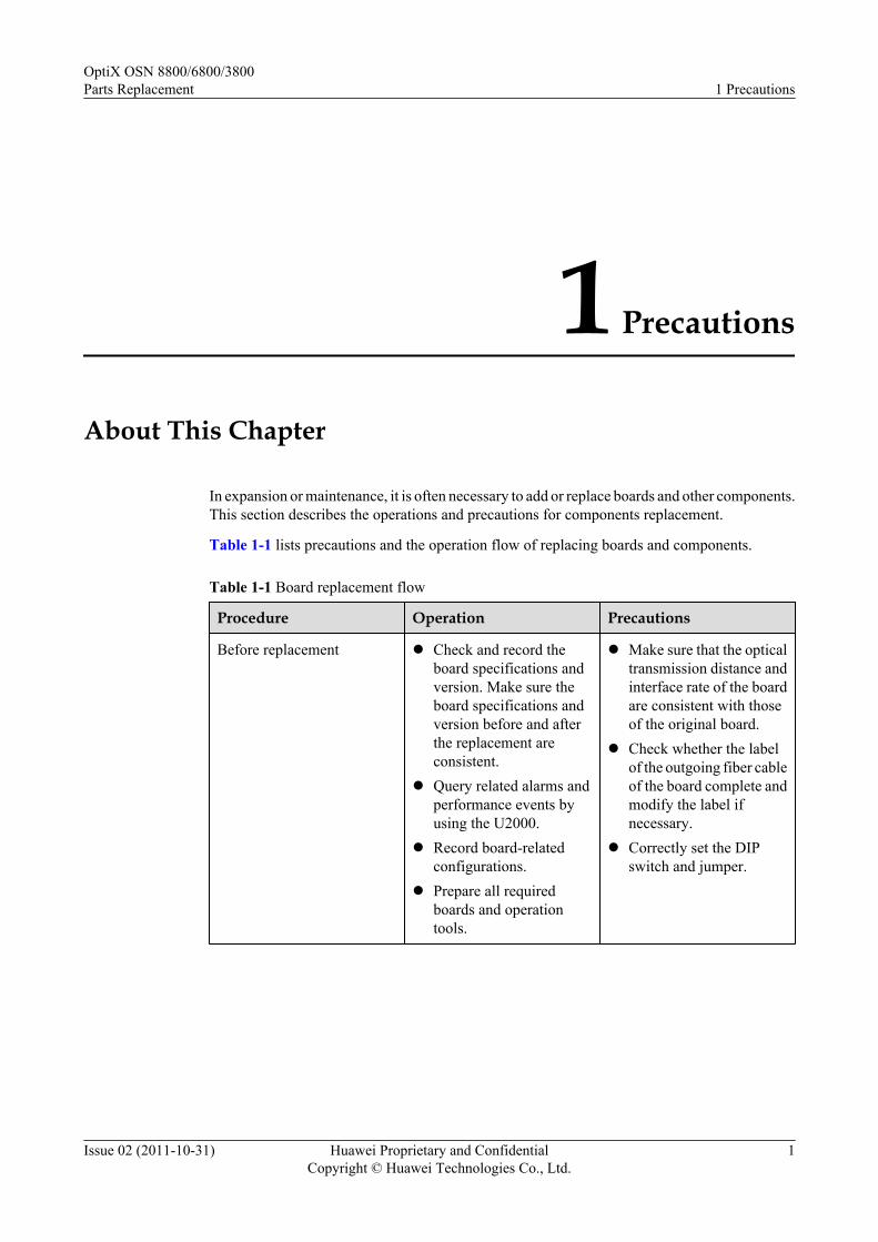
In expansion or maintenance, it is often necessary to add or replace boards and other components.This section describes the operations and precautions for components replacement.
Table 1-1 lists precautions and the operation flow of replacing boards and components.
Table 1-1 Board replacement flow
Procedure Operation Precautions
Before replacement l Check and record theboard specifications andversion. Make sure theboard specifications andversion before and afterthe replacement areconsistent.
l Query related alarms andperformance events byusing the U2000.
l Record board-relatedconfigurations.
l Prepare all requiredboards and operationtools.
l Make sure that the opticaltransmission distance andinterface rate of the boardare consistent with thoseof the original board.
l Check whether the labelof the outgoing fiber cableof the board complete andmodify the label ifnecessary.
l Correctly set the DIPswitch and jumper.
OptiX OSN 8800/6800/3800Parts Replacement 1 Precautions
Issue 02 (2011-10-31) Huawei Proprietary and ConfidentialCopyright © Huawei Technologies Co., Ltd.
1

Procedure Operation Precautions
During replacement l Wear an ESD wrist strap.l Insert or remove the board
correctly.
l Remove fibers connectedto the board beforereplacement. Connect thefiber back again after theboard is replaced.
l Record the settings of thejumper and DIP switch onthe board.
l Protect the board fromdamage during removaland replacement byfollowing standard ESDprocedures. Avoidlooking directly into fiberoptic cables to help avoideye damage.
After replacement l Check the boardindicators and make surethat the board worksnormally.
l Query related alarms andperformance events byusing the U2000, andmake sure that there is noabnormal alarm.
l Store the replaced boardin an ESD protection bagand attach a maintenancelabel to the bag. The labelmust show the NE nameand include a faultdescription.
l Make sure that the fibersare connected correctly.
l To replace an SCC board,you must re-apply theconfigurations, setperformance monitoringparameters, and back upthe database.
l For a functional boardwith a backup, check ifthe switching is normal.
l For a board without thealarm reporting function,ensure that all devicesconnected to the board areoperating correctly.
Before you replace a board or other hardware functional components of the optical networkequipment, be aware of the following information:
1.1 Specifications and VersionsWhen replacing a board, make sure that the name and version of the new board are consistentwith those of the replaced board.
1.2 LaserWhen you install and maintain equipment, follow the safety precautions described below to helpprevent personal injury or equipment damage. The laser complies with IEC60825.
1.3 Short CircuitExercise caution where you place metallic tools so that you do not cause a short circuit in anyequipment.
1.4 ESD
OptiX OSN 8800/6800/3800Parts Replacement 1 Precautions
Issue 02 (2011-10-31) Huawei Proprietary and ConfidentialCopyright © Huawei Technologies Co., Ltd.
2
During installation and maintenance, follow antistatic procedures to prevent equipment damage:
1.5 Working on Equipment with Power AppliedWhen you perform operations on the equipment when power is applied, ensure that you take thesafety precautions to prevent personal injury or equipment damage.
1.6 Alarm and Safety SymbolsDuring equipment installation and maintenance, observe the precautions indicated by the alarmand safety symbols to help prevent personal injury or equipment damage.
1.7 Correct Board Inserting and RemovingRemoving an in-service board can interrupt services. Perform board hot swapping during off-peak hours.
OptiX OSN 8800/6800/3800Parts Replacement 1 Precautions
Issue 02 (2011-10-31) Huawei Proprietary and ConfidentialCopyright © Huawei Technologies Co., Ltd.
3

1.1 Specifications and VersionsWhen replacing a board, make sure that the name and version of the new board are consistentwith those of the replaced board.
If the version is inconsistent, you must check whether the boards with different versions can bereplaced. For information about the replacement compatibility between board versions, see theHardware Description.
For OTU boards, the wavelength of the new and replaced boards must be identical. Wavelengthinformation is provided in the bar code on the front panel of the board. For details about the barcode, see the Hardware Description. You can also obtain board versions on the U2000. Fordetails, see the iManager U2000 Operation Guide for NG WDM NE Management.
NOTE
When a board is faulty and unavailable, you cannot use the U2000 to obtain version information. In somecases, you can obtain the version information by querying the engineering document records
1.2 LaserWhen you install and maintain equipment, follow the safety precautions described below to helpprevent personal injury or equipment damage. The laser complies with IEC60825.
The safety precautions of lasers consist of two parts:
l Personal injuryl Equipment damage
Personal Injury
DANGERLaser beams from the optical ports on boards or from the fiber connectors cause eye damage.Do not look directly at the optical ports or fiber connectors during the installation andmaintenance of boards or fibers. Do not shine laser beams into the eyes of other workers.
DANGERTo prevent eye damage in the case of an optical port that is in use, use protective caps to coverthe optical interface and the fiber connector after you remove the fiber from the optical interface.
OptiX OSN 8800/6800/3800Parts Replacement 1 Precautions
Issue 02 (2011-10-31) Huawei Proprietary and ConfidentialCopyright © Huawei Technologies Co., Ltd.
4
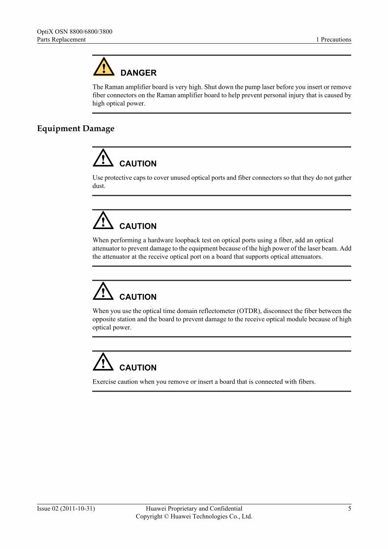
DANGERThe Raman amplifier board is very high. Shut down the pump laser before you insert or removefiber connectors on the Raman amplifier board to help prevent personal injury that is caused byhigh optical power.
Equipment Damage
CAUTIONUse protective caps to cover unused optical ports and fiber connectors so that they do not gatherdust.
CAUTIONWhen performing a hardware loopback test on optical ports using a fiber, add an opticalattenuator to prevent damage to the equipment because of the high power of the laser beam. Addthe attenuator at the receive optical port on a board that supports optical attenuators.
CAUTIONWhen you use the optical time domain reflectometer (OTDR), disconnect the fiber between theopposite station and the board to prevent damage to the receive optical module because of highoptical power.
CAUTIONExercise caution when you remove or insert a board that is connected with fibers.
OptiX OSN 8800/6800/3800Parts Replacement 1 Precautions
Issue 02 (2011-10-31) Huawei Proprietary and ConfidentialCopyright © Huawei Technologies Co., Ltd.
5

CAUTIONThe optical power of the Raman amplifier board is very high. Observe the following precautionswhen using the Raman amplifier board to prevent damage to the equipment.
l Do not use fiber connectors within 0–20 km. The fibers at every joint point must be spliced.
l The single-point additional loss within 0–10 km must be smaller than 0.1 dB (G.652) or0.2 dB (G.655) and the single-point return loss must not be smaller than 40 dB.
l The single-point additional loss within 10–20 km must be smaller than 0.2 dB (G.652) or0.4 dB (G.655) and the single-point return loss must not be smaller than 40 dB.
l Fiber connections must be complete before you enable the lasers on the Raman amplifierboard. Make sure that the fiber connectors are clean. Otherwise, the fiber connectors mightbe damaged when you insert or remove the fiber connectors.
l The optical power of the LINE interface on the Raman amplifier board is very high. TheLSH/APC optical connectors must be used in the fiber that is connected to the LINEinterface.
l For the Raman amplifier board with backward pump, the strong pump light enters the fiberthrough the input end (LINE) instead of the output end (SYS). Do not add boards or non-fiber devices, such as attenuators or fiber jumpers, at the input end.
l The bent radius of the fiber that is connected to the LINE interface on the Raman amplifierboard must be larger than 30 mm to prevent the fiber from being burned.
1.3 Short CircuitExercise caution where you place metallic tools so that you do not cause a short circuit in anyequipment.
CAUTIONDo not place tools, such as screwdrivers, on the air baffle.
CAUTIONEnsure that screws do not fall off into the subrack or chassis.
1.4 ESDDuring installation and maintenance, follow antistatic procedures to prevent equipment damage:
l Always wear an ESD wrist strap during the operation.
l Check that the equipment is securely grounded.
OptiX OSN 8800/6800/3800Parts Replacement 1 Precautions
Issue 02 (2011-10-31) Huawei Proprietary and ConfidentialCopyright © Huawei Technologies Co., Ltd.
6

CAUTIONWear a well-grounded ESD wrist strap whenever you touch equipment or boards. Make surethat the wrist strap touches your skin. Insert the ESD strap connector into the ESD socket of theequipment.
For information about how to wear an ESD wrist strap, see Figure 1-1.
Figure 1-1 Wearing an ESD wrist strap
NOTE
Insert the connector of the ESD strap into the equipment port. For details, see the Quick Installation Guide.
When you are following antistatic procedures, take the following precautions:
l Check the validity and functionality of the wrist strap. Its resistance value must be between0.75 mega ohm to 10 mega ohm. If the wrist strap validity period (usually two years) hasexpired, or if the resistance value fails to meet requirements, replace it with a wrist strapthat provides the required resistance value.
l Do not touch a board with your clothing. Clothing generates static electricity that is notprotected by the wrist strap.
l Wear an ESD wrist strap and place the board on an ESD pad when you replace boards orchips. Use ESD tweezers or extraction tools to replace chips. Do not touch chips, circuits,or pins with your bare hands.
l Keep the boards and other ESD-sensitive parts you are installing in ESD bags. Place theremoved boards and components on an ESD pad or ESD material. Do not use non-antistaticmaterials such as white foams, common plastic bags, or paper bags to pack boards, and donot let these materials touch the boards.
l Wear an ESD wrist strap when operating the ports of boards because they are also ESD-sensitive. Discharge the static electricity of cables and protective sleeves before you connectthem to the ports.
OptiX OSN 8800/6800/3800Parts Replacement 1 Precautions
Issue 02 (2011-10-31) Huawei Proprietary and ConfidentialCopyright © Huawei Technologies Co., Ltd.
7

l Keep packing materials (such as, ESD boxes and bags) available in the equipment roomfor packing boards in the future.
ESD complies with IEC Publication 1000, EN 55022, EN 55024, IEC 61000 and GR-1089-CORE.
1.5 Working on Equipment with Power AppliedWhen you perform operations on the equipment when power is applied, ensure that you take thesafety precautions to prevent personal injury or equipment damage.
DANGERDo not install or disassemble equipment when power is applied.
DANGERDo not install or remove power cables on equipment when power is applied.
1.6 Alarm and Safety SymbolsDuring equipment installation and maintenance, observe the precautions indicated by the alarmand safety symbols to help prevent personal injury or equipment damage.
Table 1-2 describes the alarm and safety symbols on the WDM equipment.
Table 1-2 Symbols on the WDM equipment
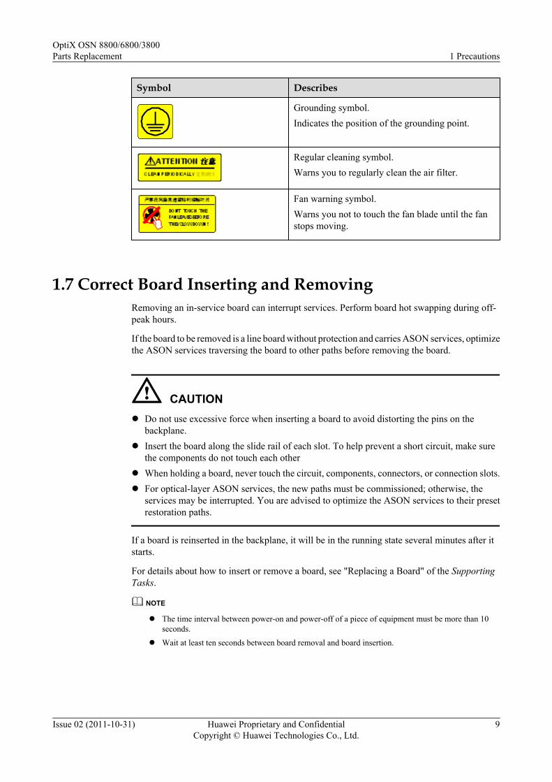
Symbol Describes
ESD protection symbol.You must wear an ESD wrist strap or glove to avoiddamage caused by electrostatic discharge to boards.
HAZARD LEVEL 1M INVISIBLE LASER RADIATION
DO NOT VIEW DIRECTLY WITH NON-ATTENUATING OPTICAL
INSTRUMENTS
CAUTION
Laser level symbol.Indicates the laser level and warns that laser beamscan cause injuries to eyes.
OptiX OSN 8800/6800/3800Parts Replacement 1 Precautions
Issue 02 (2011-10-31) Huawei Proprietary and ConfidentialCopyright © Huawei Technologies Co., Ltd.
8
Symbol Describes
Grounding symbol.Indicates the position of the grounding point.
Regular cleaning symbol.Warns you to regularly clean the air filter.
Fan warning symbol.Warns you not to touch the fan blade until the fanstops moving.
1.7 Correct Board Inserting and RemovingRemoving an in-service board can interrupt services. Perform board hot swapping during off-peak hours.
If the board to be removed is a line board without protection and carries ASON services, optimizethe ASON services traversing the board to other paths before removing the board.
CAUTIONl Do not use excessive force when inserting a board to avoid distorting the pins on the
backplane.l Insert the board along the slide rail of each slot. To help prevent a short circuit, make sure
the components do not touch each otherl When holding a board, never touch the circuit, components, connectors, or connection slots.l For optical-layer ASON services, the new paths must be commissioned; otherwise, the
services may be interrupted. You are advised to optimize the ASON services to their presetrestoration paths.
If a board is reinserted in the backplane, it will be in the running state several minutes after itstarts.
For details about how to insert or remove a board, see "Replacing a Board" of the SupportingTasks.
NOTE
l The time interval between power-on and power-off of a piece of equipment must be more than 10seconds.
l Wait at least ten seconds between board removal and board insertion.
OptiX OSN 8800/6800/3800Parts Replacement 1 Precautions
Issue 02 (2011-10-31) Huawei Proprietary and ConfidentialCopyright © Huawei Technologies Co., Ltd.
9

2 Component Category
Boards are classified into different types, such as the optical transponder board, the opticalmultiplexer and demultiplexer board, the optical add and drop multiplexing board, and the opticalamplifier board, and so on.
l Table 2-1 lists the types and replacement precautions of boards in the OptiX OSN 8800.l Table 2-2 lists the types and replacement precautions of boards in the OptiX OSN 6800.l Table 2-3 lists the types and replacement precautions of boards in the OptiX OSN 3800.
Table 2-1 Board classification of the OptiX OSN 8800
Component Boards Precautions for BoardReplacement
OTU board LDM, LDMD, LDMS, LOG,LOM, LQM, LQMD,LQMS, LSQ, LSX, LSXL,LSXLR, LSXR, LWXS,TMX, LDX, LEM24, LEX4,LOA
The new board must matchthe replaced board in type,working wavelength, opticalmodule, and softwareversion.NOTE
For information aboutreplacement compatibilitybetween different versions of aboard, see the HardwareDescription.
Tributary board TDX, TOM, TQX, TSXL,TOG, TOA, THA
The new board must matchthe replaced board in type,working wavelength, opticalmodule, and softwareversion.NOTE
For information aboutreplacement compatibilitybetween different versions of aboard, see the HardwareDescription.
OptiX OSN 8800/6800/3800Parts Replacement 2 Component Category
Issue 02 (2011-10-31) Huawei Proprietary and ConfidentialCopyright © Huawei Technologies Co., Ltd.
10
Component Boards Precautions for BoardReplacement
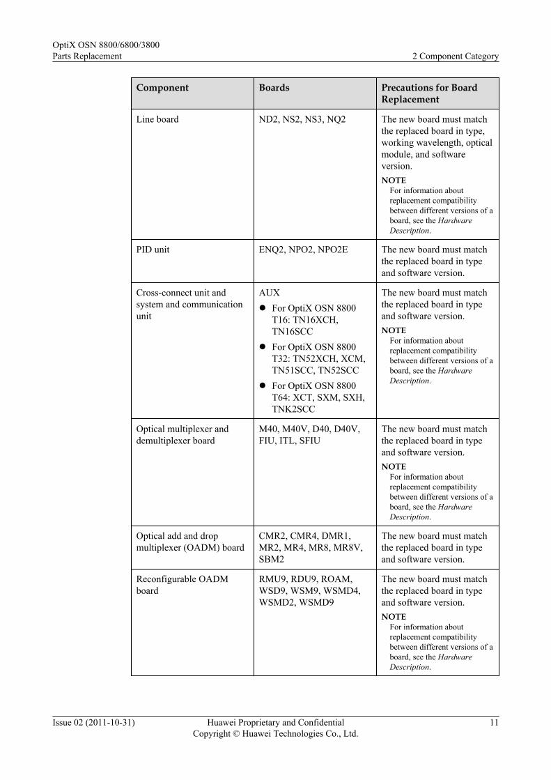
Line board ND2, NS2, NS3, NQ2 The new board must matchthe replaced board in type,working wavelength, opticalmodule, and softwareversion.NOTE
For information aboutreplacement compatibilitybetween different versions of aboard, see the HardwareDescription.
PID unit ENQ2, NPO2, NPO2E The new board must matchthe replaced board in typeand software version.
Cross-connect unit andsystem and communicationunit
AUXl For OptiX OSN 8800
T16: TN16XCH,TN16SCC
l For OptiX OSN 8800T32: TN52XCH, XCM,TN51SCC, TN52SCC
l For OptiX OSN 8800T64: XCT, SXM, SXH,TNK2SCC
The new board must matchthe replaced board in typeand software version.NOTE
For information aboutreplacement compatibilitybetween different versions of aboard, see the HardwareDescription.
Optical multiplexer anddemultiplexer board
M40, M40V, D40, D40V,FIU, ITL, SFIU
The new board must matchthe replaced board in typeand software version.NOTE
For information aboutreplacement compatibilitybetween different versions of aboard, see the HardwareDescription.
Optical add and dropmultiplexer (OADM) board
CMR2, CMR4, DMR1,MR2, MR4, MR8, MR8V,SBM2
The new board must matchthe replaced board in typeand software version.
Reconfigurable OADMboard
RMU9, RDU9, ROAM,WSD9, WSM9, WSMD4,WSMD2, WSMD9
The new board must matchthe replaced board in typeand software version.NOTE
For information aboutreplacement compatibilitybetween different versions of aboard, see the HardwareDescription.
OptiX OSN 8800/6800/3800Parts Replacement 2 Component Category
Issue 02 (2011-10-31) Huawei Proprietary and ConfidentialCopyright © Huawei Technologies Co., Ltd.
11

Component Boards Precautions for BoardReplacement
Optical amplifier board CRPC, HBA, OAU1, OBU1,OBU2, DAS1
Check the input opticalpower of the amplifieragainst excessive opticalpower that damages opticalcomponents of the newboard.NOTE
For information aboutreplacement compatibilitybetween different versions of aboard, see the HardwareDescription.
Clock unit STG The new board must matchthe replaced board in typeand software version.
Optical supervisory channelboard
SC1, SC2, HSC1, ST2 The new board must matchthe replaced board in typeand software version.NOTE
For information aboutreplacement compatibilitybetween different versions of aboard, see the HardwareDescription.
Optical protection board DCP, OLP, SCS The new board must matchthe replaced board in typeand software version.NOTE
For information aboutreplacement compatibilitybetween different versions of aboard, see the HardwareDescription.
Spectrum analyzer board MCA4, MCA8, WMU,OPM8
The new board must matchthe replaced board in typeand software version.
Variable optical attenuatorboard
VA1, VA4 The new board must matchthe replaced board in typeand software version.NOTE
For information aboutreplacement compatibilitybetween different versions of aboard, see the HardwareDescription.
OptiX OSN 8800/6800/3800Parts Replacement 2 Component Category
Issue 02 (2011-10-31) Huawei Proprietary and ConfidentialCopyright © Huawei Technologies Co., Ltd.
12

Component Boards Precautions for BoardReplacement
Optical power and dispersionequalizing board
DCU, TDC The new board must matchthe replaced board in typeand software version.
OCS system unit BPA, DCU, EAS2, EGSH,SF64, SF64A, SFD64, SL64,SLD64, SLH41, SLO16,SLQ16, SLQ64
The new board must matchthe replaced board in typeand software version.
ROPA subsystem unit GFU, RGU, ROP The new board must matchthe replaced board in typeand software version.
Interface area unit PIU, EFI1, EFI2, EFI, , STI,ATE
The new board must matchthe replaced board in typeand software version.
Fan tray assembly FAN The new board must matchthe replaced board in typeand software version.
Table 2-2 Board classification of the OptiX OSN 6800
Component Boards Precautions for BoardReplacement
OTU board ECOM, L4G, LDGD, LDGS,LDM, LDMD, LDMS, LOG,LOM, LQG, LQM, LQMD,LQMS, LSQ, LSX, LSXL,LSXLR, LSXR, LWX2,LWXD, LWXS, TMX, LDX,LEM24, LEX4, LOA
The new board must matchthe replaced board in type,working wavelength, opticalmodule, and softwareversion.NOTE
For information aboutreplacement compatibilitybetween different versions of aboard, see the HardwareDescription.
Tributary board TBE, TDG, TDX, TOM,TQM, TQS, TQX, TSXL,TOG
The new board must matchthe replaced board in type,working wavelength, opticalmodule, and softwareversion.NOTE
For information aboutreplacement compatibilitybetween different versions of aboard, see the HardwareDescription.
OptiX OSN 8800/6800/3800Parts Replacement 2 Component Category
Issue 02 (2011-10-31) Huawei Proprietary and ConfidentialCopyright © Huawei Technologies Co., Ltd.
13

Component Boards Precautions for BoardReplacement
Line board ND2, NS2, NS3, NQ2 The new board must matchthe replaced board in type,working wavelength, opticalmodule, and softwareversion.NOTE
For information aboutreplacement compatibilitybetween different versions of aboard, see the HardwareDescription.
PID unit BMD4, BMD8, ELQX,PTQX
The new board must matchthe replaced board in typeand software version.
Cross-connect unit andsystem and communicationunit
XCS, SCC, AUX The new board must matchthe replaced board in type,working wavelength, opticalmodule, and softwareversion.NOTE
For information aboutreplacement compatibilitybetween different versions of aboard, see the HardwareDescription.
Optical multiplexer anddemultiplexer board
M40, M40V, D40, D40V,FIU, ITL, SFIU
The new board must matchthe replaced board in typeand software version.NOTE
For information aboutreplacement compatibilitybetween different versions of aboard, see the HardwareDescription.
Optical add and dropmultiplexer (OADM) board
CMR2, CMR4, DMR1,MR2, MR4, MR8, MR8V,SBM2
The new board must matchthe replaced board in typeand software version.
Reconfigurable OADMboard
RMU9, RDU9, ROAM,WSD9, WSM9, WSMD4,WSMD2, WSMD9
The new board must matchthe replaced board in typeand software version.NOTE
For information aboutreplacement compatibilitybetween different versions of aboard, see the HardwareDescription.
OptiX OSN 8800/6800/3800Parts Replacement 2 Component Category
Issue 02 (2011-10-31) Huawei Proprietary and ConfidentialCopyright © Huawei Technologies Co., Ltd.
14

Component Boards Precautions for BoardReplacement
Optical amplifier board CRPC, HBA, OAU1, OBU1,OBU2, DAS1, OBU1P1
Check the input opticalpower of the amplifieragainst excessive opticalpower that damages opticalcomponents of the newboard.NOTE
For information aboutreplacement compatibilitybetween different versions of aboard, see the HardwareDescription.
Clock board STG The new board must matchthe replaced board in typeand software version.
Optical supervisory channelboard
SC1, SC2, HSC1, ST2 The new board must matchthe replaced board in typeand software version.NOTE
For information aboutreplacement compatibilitybetween different versions of aboard, see the HardwareDescription.
Optical protection board DCP, OLP, SCS The new board must matchthe replaced board in typeand software version.NOTE
For information aboutreplacement compatibilitybetween different versions of aboard, see the HardwareDescription.
Spectrum analyzer board MCA4, MCA8, WMU,OPM8
The new board must matchthe replaced board in typeand software version.
Variable optical attenuatorboard
VA1, VA4 The new board must matchthe replaced board in typeand software version.NOTE
For information aboutreplacement compatibilitybetween different versions of aboard, see the HardwareDescription.
OptiX OSN 8800/6800/3800Parts Replacement 2 Component Category
Issue 02 (2011-10-31) Huawei Proprietary and ConfidentialCopyright © Huawei Technologies Co., Ltd.
15

Component Boards Precautions for BoardReplacement
Optical power and dispersionequalizing board
DCU, TDC The new board must matchthe replaced board in typeand software version.
ROPA subsystem unit GFU, RGU, ROP The new board must matchthe replaced board in typeand software version.
Interface area unit PIU, EFI1 The new board must matchthe replaced board in typeand software version.
Fan tray assembly FAN The new board must matchthe replaced board in typeand software version.
Table 2-3 Board classification of the OptiX OSN 3800
Component Boards Precautions for BoardReplacement
OTU board ECOM, L4G, LDGD, LDGS,LDM, LDMD, LDMS, LOG,LOM, LQG, LQM, LQMD,LQMS, LSX, LSXR, LWX2,LWXD, LWXS, TMX,LDX, LOA
The new board must matchthe replaced board in type,working wavelength, opticalmodule, and softwareversion.NOTE
For information aboutreplacement compatibilitybetween different versions of aboard, see the HardwareDescription.
Tributary board TBE, TDG, TDX, TOM,TQM, TQS, TOG
The new board must matchthe replaced board in type,working wavelength, opticalmodule, and softwareversion.NOTE
For information aboutreplacement compatibilitybetween different versions of aboard, see the HardwareDescription.
OptiX OSN 8800/6800/3800Parts Replacement 2 Component Category
Issue 02 (2011-10-31) Huawei Proprietary and ConfidentialCopyright © Huawei Technologies Co., Ltd.
16

Component Boards Precautions for BoardReplacement
Line board NS2 The new board must matchthe replaced board in type,working wavelength, opticalmodule, and softwareversion.NOTE
For information aboutreplacement compatibilitybetween different versions of aboard, see the HardwareDescription.
Optical multiplexer anddemultiplexer board
DFIU, FIU The new board must matchthe replaced board in typeand software version.NOTE
For information aboutreplacement compatibilitybetween different versions of aboard, see the HardwareDescription.
Optical add and dropmultiplexer (OADM) board
CMR1, CMR2, CMR4,DMR1, MR2, MR4, SBM2
The new board must matchthe replaced board in typeand software version.
Optical amplifier board OAU1, OBU1, OBU2,DAS1
Check the input opticalpower of the amplifieragainst excessive opticalpower that damages opticalcomponents of the newboard.NOTE
For information aboutreplacement compatibilitybetween different versions of aboard, see the HardwareDescription.
System control, supervisionand communication board
SCC, AUX The new board must matchthe replaced board in typeand software version.NOTE
For information aboutreplacement compatibilitybetween different versions of aboard, see the HardwareDescription.
OptiX OSN 8800/6800/3800Parts Replacement 2 Component Category
Issue 02 (2011-10-31) Huawei Proprietary and ConfidentialCopyright © Huawei Technologies Co., Ltd.
17

Component Boards Precautions for BoardReplacement
Optical supervisory channelboard
SC1, SC2, HSC1,ST2 The new board must matchthe replaced board in typeand software version.NOTE
For information aboutreplacement compatibilitybetween different versions of aboard, see the HardwareDescription.
Optical protection board DCP, OLP, SCS The new board must matchthe replaced board in typeand software version.NOTE
For information aboutreplacement compatibilitybetween different versions of aboard, see the HardwareDescription.
Spectrum analyzer board MCA4, MCA8, OPM8 The new board must matchthe replaced board in typeand software version.
Variable optical attenuatorboard
VA1, VA4 The new board must matchthe replaced board in typeand software version.NOTE
For information aboutreplacement compatibilitybetween different versions of aboard, see the HardwareDescription.
Optical power and dispersionequalizing board
DCU The new board must matchthe replaced board in typeand software version.
Interface area unit PIU, APIU The new board must matchthe replaced board in typeand software version.
Fan tray assembly FAN The new board must matchthe replaced board in typeand software version.
OptiX OSN 8800/6800/3800Parts Replacement 2 Component Category
Issue 02 (2011-10-31) Huawei Proprietary and ConfidentialCopyright © Huawei Technologies Co., Ltd.
18

3 Tools and Instruments
The tools and instruments described in this chapter are required when you replace components.
Table 3-1 lists the tools and instruments that are required in component replacement.
Table 3-1 Tools/Instruments required
No. Tools/Instruments Usage
1 ESD wrist strap Prevents the electrostaticenergy generated by thehuman body from damagingstatic-sensitive components.
2 ESD bag Contains static-sensitivecomponents.
3 Cross screwdriver Required to install or removea board and subrack powercables.
4 Multimeter Tests the voltage of the PDUand the battery of the SCC.
5 U2000 Allows you to query alarms,upload and download data,and perform switching.
6 Web LCT Allows you to create an NEand modify the IP addressafter you replace the SCC.
7 Optical power meter Tests optical power.
OptiX OSN 8800/6800/3800Parts Replacement 3 Tools and Instruments
Issue 02 (2011-10-31) Huawei Proprietary and ConfidentialCopyright © Huawei Technologies Co., Ltd.
19

4 Replacing the SCC Board with One of theSame PCB Version
About This Chapter
This section describes how to replace a SCC board with one of the same PCB version.
l In OptiX OSN 8800 T16, the SCC board takes one slot in the subrack. The valid slots forthe SCC board are IU9 and IU10. IU9 is the first choice. If there is 1+1 protection for theSCC board, IU10 is the default slot for the standby SCC.
l In OptiX OSN 8800 T32, the SCC board takes one slot in the subrack. The valid slots forthe SCC board are IU11 and IU28. IU28 is the first choice. If there is 1+1 protection forthe SCC board, IU11 is the default slot for the standby SCC.
l In OptiX OSN 8800 T64, the SCC board takes one slot in the subrack. The valid slots forthe SCC board are IU74 and IU85. IU74 is the first choice. If there is 1+1 protection forthe SCC board, IU85 is the default slot for the standby SCC.
l In OptiX OSN 6800, the SCC board takes one slot in the subrack. The valid slots for theSCC board are IU17 and IU18. IU18 is the first choice. If there is 1+1 protection for theSCC board, IU17 is the default slot for the standby SCC.
l In OptiX OSN 3800, the SCC board takes one slot in the subrack. The valid slots for theSCC board are IU8 and IU9. IU9 is the first choice. If there is 1+1 protection for the SCCboard, IU8 is the default slot for the standby SCC.
NOTE
In the case of SCC 1+1 protection, the data on the active SCC board is synchronized to the standby SCCboard after the standby board is replaced. No manual setting of NE ID is required on the standby board.
When the 1+1 protection is not provided, NE ID must be set. Consult Huawei technical support engineersbefore replacing an SCC board.
OptiX OSN 8800/6800/3800Parts Replacement
4 Replacing the SCC Board with One of the Same PCBVersion
Issue 02 (2011-10-31) Huawei Proprietary and ConfidentialCopyright © Huawei Technologies Co., Ltd.
20

CAUTIONDo not remove the SCC board during batch data backup to help avoid unsynchronized data.Do not directly insert a standby SCC board that is removed from an ASON NE in to the mastersubrack of another ASON NE so that the SCC board functions as the active SCC board of thelatter NE. Before inserting the SCC board, ensure that the node ID and OSPF IP address that aresaved on the SCC board are unique on the entire ASON network.
For OptiX OSN 8800/6800, you can replace the SCC board when:
l The SCC board of the master subrack is configured with SCC 1+1 protection.l There is no protection for the SCC board of the master subrack.l Replacing the SCC board of the slave subrack.
For OptiX OSN 3800, The SCC can be replaced when:
l The SCC board of the master subrack is configured with SCC 1+1 protection.l There is no protection for the SCC board.
4.1 Setting the Battery Jumper on the SCCThis section describes how to set the battery jumper on the spare SCC board before replacingthe SCC board.
4.2 Replacing the Protected SCC Board in a Master SubrackThis section describes how to replace the SCC board of the master subrack when SCC 1+1protection is configured.
4.3 Replacing the Unprotected SCC Board in a Master SubrackThis section describes how to replace an SCC board in the master subrack when no protectionis configured for the SCC board.
4.4 Replacing the SCC Board in a Slave SubrackThis section describes how to replace an SCC board in a slave subrack.
OptiX OSN 8800/6800/3800Parts Replacement
4 Replacing the SCC Board with One of the Same PCBVersion
Issue 02 (2011-10-31) Huawei Proprietary and ConfidentialCopyright © Huawei Technologies Co., Ltd.
21

4.1 Setting the Battery Jumper on the SCCThis section describes how to set the battery jumper on the spare SCC board before replacingthe SCC board.
Impact on SystemThere are no impacts on the system.
Tools, Equipment, and MaterialsESD wrist strap
Background InformationThe battery on the SCC ensures that the configuration data on the SCC is retained in case of apower failure of the SCC. After the board is in use, place a jumper cap over the battery jumperto make a short circuit, and thus the battery supplies power normally. When the board is not inuse, use a jumper cap to disconnect the battery jumper.
l OptiX OSN 8800 T16 supports the TN16SCC board, Figure 4-2 shows the position ofbattery jumper on the board.
l OptiX OSN 8800 T32 supports the TN51SCC board and TN52SCC board, Figure 4-5 andFigure 4-6 show the position of battery jumper on the board.
l OptiX OSN 8800 T64 supports the TNK2SCC board, Figure 4-4 shows the position ofbattery jumper on the board.
l OptiX OSN 6800 supports the TN11SCC board, TN51SCC board and TN52SCC board,Figure 4-1, Figure 4-5 and Figure 4-6 show the position of battery jumper on the board.
l OptiX OSN 3800 supports the TN21SCC board and TN22SCC board, Figure 4-3 showsthe position of battery jumper on the board.
Figure 4-7 shows the battery jumper. When the battery is required, place a jumper cap over pin3 and pin 2. When the battery is not required, place a jumper cap over pin 2 and pin 1.
OptiX OSN 8800/6800/3800Parts Replacement
4 Replacing the SCC Board with One of the Same PCBVersion
Issue 02 (2011-10-31) Huawei Proprietary and ConfidentialCopyright © Huawei Technologies Co., Ltd.
22

Figure 4-1 Position of the battery jumper on the TN11SCC
CPU
Battery jumper
CFCard
1
2
3
Battery jumper
01020304
BIOS Running Mode
OptiX OSN 8800/6800/3800Parts Replacement
4 Replacing the SCC Board with One of the Same PCBVersion
Issue 02 (2011-10-31) Huawei Proprietary and ConfidentialCopyright © Huawei Technologies Co., Ltd.
23

Figure 4-2 Position of the battery jumper on the TN16SCC
CF Card
Battery Jumper
3 2 1
J1SW1
OFF
ON
431 2
BIOS Running
Mode
OptiX OSN 8800/6800/3800Parts Replacement
4 Replacing the SCC Board with One of the Same PCBVersion
Issue 02 (2011-10-31) Huawei Proprietary and ConfidentialCopyright © Huawei Technologies Co., Ltd.
24

Figure 4-3 Position of the battery jumper on the TN21/TN22SCC
CPU
Battery jumper
1
2
3
Battery jumper
J13J14
BIOS Running Mode
TN21SCC
CPU
Battery jumper
1
2
3
Battery jumper
J11J13
BIOS Running Mode
TN22SCC
OptiX OSN 8800/6800/3800Parts Replacement
4 Replacing the SCC Board with One of the Same PCBVersion
Issue 02 (2011-10-31) Huawei Proprietary and ConfidentialCopyright © Huawei Technologies Co., Ltd.
25

Figure 4-4 Position of the battery jumper on the TNK2SCC
J44
Battery Jumper
CPU
3 21B
attery Supply CF
J9
01020304
BIOS Running Mode
Figure 4-5 Position of the battery jumper on the TN51SCC
Battery Supply
U42J12
J42
3 2 1CPU
J1
U45
CF Card
Battery Jumper
BIOS Running Mode
01020304
OptiX OSN 8800/6800/3800Parts Replacement
4 Replacing the SCC Board with One of the Same PCBVersion
Issue 02 (2011-10-31) Huawei Proprietary and ConfidentialCopyright © Huawei Technologies Co., Ltd.
26

Figure 4-6 Position of the battery jumper on the TN52SCC
Battery Supply
U33 U18
CF Card
Jumper 3 2
1C
PU
J1
Battery
J11
01020304
BIOS Running Mode
Figure 4-7 Battery jumper positions
123
Whenbattery isrequired
Whenbattery is
notrequired
4.2 Replacing the Protected SCC Board in a Master SubrackThis section describes how to replace the SCC board of the master subrack when SCC 1+1protection is configured.
Prerequisitel You must be an NM user with "NE and network operator" authority or higher.
l The FTP/TFTP/SFTP server is configured and the FTP/TFTP/SFTP service is started. Formore information, see the U2000 NE Software Management.
OptiX OSN 8800/6800/3800Parts Replacement
4 Replacing the SCC Board with One of the Same PCBVersion
Issue 02 (2011-10-31) Huawei Proprietary and ConfidentialCopyright © Huawei Technologies Co., Ltd.
27

l The SCC replacement board must be the same type as the SCC board being replaced.
Impact on SystemReplacing an SCC board configured with protection does not affect the existing services.
In the case of SCC 1+1 protection, replacing one of the SCC in the protection group does notinterrupt communication between the NE where the SCC board resides and the U2000 after youswitch services from one SCC board to the other SCC board.
Tools, Equipment, and MaterialsESD bag, U2000, multimeter
Background InformationBefore an SCC board is replaced with a spare board, you must set the battery jumper on the spareSCC board with reference to 4.1 Setting the Battery Jumper on the SCC.
You must clear the database on the spare SCC board before starting the replacement. You clearthe database by configuring the BIOS running mode by using four setting jumpers on the spareSCC board. The figure below shows the four jumpers for setting the BIOS running mode andthe battery jumper on an SCC board. The four jumpers for setting the BIOS running mode arearranged from high order to low order and identified as 04, 03, 02, and 01.
The setting of each jumper corresponds to a binary value, either 0 or 1. When a jumper is notcapped, the setting corresponds to binary 0. When the jumper is capped, the setting correspondsto binary 1. The settings of the four jumpers can be arranged in 16 combinations, representing0 to 15 in the decimal system. The default setting of the four jumpers is 0000.
OptiX OSN 8800/6800/3800Parts Replacement
4 Replacing the SCC Board with One of the Same PCBVersion
Issue 02 (2011-10-31) Huawei Proprietary and ConfidentialCopyright © Huawei Technologies Co., Ltd.
28

Figure 4-8 Position of the BIOS running mode jumper on the TN11SCC
CPU
Battery jumper
CFCard
1
2
3
Battery jumper
01020304
BIOS Running Mode
OptiX OSN 8800/6800/3800Parts Replacement
4 Replacing the SCC Board with One of the Same PCBVersion
Issue 02 (2011-10-31) Huawei Proprietary and ConfidentialCopyright © Huawei Technologies Co., Ltd.
29

Figure 4-9 Position of the BIOS running mode jumper on the TN16SCC
CF Card
Battery Jumper
3 2 1
J1SW1
OFF
ON
431 2
BIOS Running
Mode
OptiX OSN 8800/6800/3800Parts Replacement
4 Replacing the SCC Board with One of the Same PCBVersion
Issue 02 (2011-10-31) Huawei Proprietary and ConfidentialCopyright © Huawei Technologies Co., Ltd.
30

Figure 4-10 Position of the BIOS running mode jumper on the TN21/TN22SCC
CPU
Battery jumper
1
2
3
Battery jumper
J13J14
BIOS Running Mode
TN21SCC
CPU
Battery jumper
1
2
3
Battery jumper
J11J13
BIOS Running Mode
TN22SCC
OptiX OSN 8800/6800/3800Parts Replacement
4 Replacing the SCC Board with One of the Same PCBVersion
Issue 02 (2011-10-31) Huawei Proprietary and ConfidentialCopyright © Huawei Technologies Co., Ltd.
31

Figure 4-11 Position of the BIOS running mode jumper on the TNK2SCC
J44
Battery Jumper
CPU
3 21B
attery Supply CF
J9
01020304
BIOS Running Mode
Figure 4-12 Position of the BIOS running mode jumper on the TN51SCC
Battery Supply
U42J12
J42
3 2 1CPU
J1
U45
CF Card
Battery Jumper
BIOS Running Mode
01020304
OptiX OSN 8800/6800/3800Parts Replacement
4 Replacing the SCC Board with One of the Same PCBVersion
Issue 02 (2011-10-31) Huawei Proprietary and ConfidentialCopyright © Huawei Technologies Co., Ltd.
32

Figure 4-13 Position of the BIOS running mode jumper on the TN52SCC
Battery Supply
U33 U18
CF Card
Jumper 3 2
1C
PU
J1
Battery
J11
01020304
BIOS Running Mode
Figure 4-14 Setting the BIOS running mode to 1111
01
02
03
04
52SCC
01
02
03
04
51SCC
01 02 03 04
K2SCC
OptiX OSN 8800/6800/3800Parts Replacement
4 Replacing the SCC Board with One of the Same PCBVersion
Issue 02 (2011-10-31) Huawei Proprietary and ConfidentialCopyright © Huawei Technologies Co., Ltd.
33

0401 02 03
11SCC
ON
OFF1 2 43
The Lowest Site
ON=1
OFF=0
TN16SCC
The Highest Site
0102
J13 J14
0304
TN21SCC
0102
J11
J130304
TN22SCC
Procedure
Step 1 Select a spare SCC board as the replacement board. Ensure that the spare SCC board and theSCC board to be replaced have the same name and are of the same type.
NOTEThe 1X3 battery jumper on the replacement board enables or disables the power supply from the battery.Ensure that pin 1 and pin 2 of this jumper are capped. Then, remove the cap of pin 1 and cap pin 3 on thejumper and use a multimeter to measure the battery voltage. If the voltage is lower than 3 V, the battery isnot working. The selected SCC board cannot be used as a replacement board.
OptiX OSN 8800/6800/3800Parts Replacement
4 Replacing the SCC Board with One of the Same PCBVersion
Issue 02 (2011-10-31) Huawei Proprietary and ConfidentialCopyright © Huawei Technologies Co., Ltd.
34

Step 2 Review and record the current alarms on the NE. For more information, refer to "Querying theCurrent Alarms" of the Supporting Tasks.
Step 3 Back up the NE database to the NMS server. This is to record the NE database when the SCCboard is replaced for future reference.
1. In the Main Topology view, choose Administration > NE Software Management > NEData Backup/Restoration from the Main Menu.
2. Right click the device(s) that you want to backup in the NE View table.
NOTE
The Backup Information tab is unavailable when multiple devices are selected.
3. Select Backup... to open the Backup dialog.
4. Select the option NMS Server or NMS Client to backup the selected device information.
NOTE
By default the NMS Server is selected. If the NMS Server is selected, the selected device informationis stored on the NMS server.
5. Optional: If the NMS Client is selected, click to select the location where the devicedata have to be backed up.
6. Click Start to start the backup operation for the selected device(s). On the NE View tabpage, the backup progress is displayed.
7. When the backup operation is successful, the NMS creates the dbf.pkg file in the NEName/yyyymmddhhmmss directory. "NEName" indicates the name of the NE, "yyyymmdd"indicates the date when the backup is created, and "hhmmss" indicates the time when thebackup is created.
Step 4 Follow the steps below to review the working state of the board to be replaced.
1. In the NE Explorer, click the NE and choose Configuration > Board 1+1 Protection fromthe Function Tree.
2. Click Query.
Step 5 If the board to be replaced is the active board, go to Step 6. Otherwise, go to Step 7.
Step 6 If the board to be replaced is the working board, follow the steps below to perform an active/standby switching on the U2000.
1. In the Main Topology, right-click the desire NE and click NE Explorer from the shortcutmenu. The NE Explorer window is displayed.
2. Choose Configuration > Board 1+1 Protection from the Function Tree.
3. In Board 1+1 Protection, right-click the desired SCC Board 1+1 Protection. SelectWorking/Protection Switching from the shortcut menu. Click OK in the windowdisplayed.
4. Click Query. If the Active Board is not the board to be replaced, the switching is successful.
5. Query the alarms and performance events on the U2000. Check if services are normal. Ifservices are normal, there must be no new abnormal alarms or performances. The switchingis successful.
Step 7 Inform the onsite maintenance engineer and replace the board. For details about how to removea board, see "Replacing a Board" of the Supporting Tasks.
OptiX OSN 8800/6800/3800Parts Replacement
4 Replacing the SCC Board with One of the Same PCBVersion
Issue 02 (2011-10-31) Huawei Proprietary and ConfidentialCopyright © Huawei Technologies Co., Ltd.
35
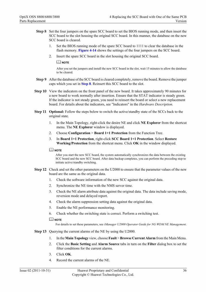
Step 8 Set the four jumpers on the spare SCC board to set the BIOS running mode, and then insert theSCC board to the slot housing the original SCC board. In this manner, the database on the newSCC board is cleared.1. Set the BIOS running mode of the spare SCC board to 1111 to clear the database in the
flash memory. Figure 4-14 shows the settings of the four jumpers on the SCC board.2. Insert the spare SCC board in the slot housing the original SCC board.
NOTE
After you set the jumpers and install the new SCC board in the slot, wait 15 minutes to allow the databaseto be cleared.
Step 9 After the database of the SCC board is cleared completely, remove the board. Remove the jumpercaps which you set in Step 8. Reinsert this SCC board to the slot.
Step 10 View the indicators on the front panel of the new board. It takes approximately 90 minutes fora new board to work normally after insertion. Ensure that the STAT indicator is steady green.If the indicator is not steady green, you need to reinsert the board or select a new replacementboard. For details about the indicators, see "Indicators" in the Hardware Description.
Step 11 Optional: Follow the steps below to switch the active/standby state of the SCCs back to theoriginal state.
1. In the Main Topology, right-click the desire NE and click NE Explorer from the shortcutmenu. The NE Explorer window is displayed.
2. Choose Configuration > Board 1+1 Protection from the Function Tree.3. In Board 1+1 Protection, right-click SCC Board 1+1 Protection. Select Restore
Working/Protection from the shortcut menu. Click OK in the window displayed.
NOTEAfter you start the new SCC board, the system automatically synchronizes the data between the existingSCC board and the new SCC board. After data backup completes, you can perform the preceding step toinitiate active/standby switching.
Step 12 Check and set the other parameters on the U2000 to ensure that the parameter values of the newboard are the same as the original data.1. Check the software information of the new SCC against the original data.2. Synchronize the NE time with the NMS server time.3. Check the NE alarm attribute data against the original data. The data include saving mode,
reversion mode and delayed report.4. Check the alarm suppression setting data against the original data.5. Enable the NE performance monitoring.6. Check whether the switching state is correct. Perform a switching test.
NOTEFor details to set these parameters, see iManager U2000 Operator Guide for NG WDM NE Management.
Step 13 Querying the current alarms of the NE by using the U2000.
1. In the Main Topology view, choose Fault > Browse Current Alarm from the Main Menu.2. Click the Basic Setting and Alarm Source tabs in turn on the Filter dialog box to set the
filter conditions for the current alarms.3. Click OK.4. Record the current alarms of the NE.
OptiX OSN 8800/6800/3800Parts Replacement
4 Replacing the SCC Board with One of the Same PCBVersion
Issue 02 (2011-10-31) Huawei Proprietary and ConfidentialCopyright © Huawei Technologies Co., Ltd.
36

NOTEYou can select the desired alarms and right-click to choose Save > Save Selected Records, or right-click to choose Save > Save All Records from the shortcut menu to save the current alarms of theNE.
NOTEAfter replacing the SCC is replaced, ensure that the monitoring of the POWER_FAIL alarm is enabled. Ifthe POWER_FAIL alarm occurs, and the alarm parameter is 0x5 0xff 0xff 0xff 0xff, the battery of the SCCboard is abnormal, check whether the jumper cap is correctly placed over the battery jumper. If yes, use amultimeter to measure the battery voltage. If the voltage is lower than 3 V, the battery is out of work. Theboard must be replaced.
CAUTIONThe standard voltage of the battery is 3.6 V. The battery is fixed on the board and cannot bereplaced.
----End
4.3 Replacing the Unprotected SCC Board in a MasterSubrack
This section describes how to replace an SCC board in the master subrack when no protectionis configured for the SCC board.
Table 4-1 Modes of replacing the SCC of the master subrack without protection
Scenario Mode Remarks
The NE is reachable on theU2000.
Backing up the NEdatabase to the U2000.
The database of the NE must bebacked up. After replacing theSCC, restore the database to theNE.The first mode is recommended.If a slot is available for anotherSCC, configure the system toprovide 1+1 SCC protection.
Backing up the NEdatabase to a CF board
The NE isnotreachableon theU2000.
A backupdatabase isstored on theU2000.
Backing up the NEdatabase to the U2000
The current database of the NEcannot be backed up. After theSCC is replaced, the NE can onlyread the database on the U2000or the database on the CF cardsaved during the last backup.No backup
database isstored on theU2000.
Backing up the NEdatabase to a CF board
OptiX OSN 8800/6800/3800Parts Replacement
4 Replacing the SCC Board with One of the Same PCBVersion
Issue 02 (2011-10-31) Huawei Proprietary and ConfidentialCopyright © Huawei Technologies Co., Ltd.
37

Scenario Mode Remarks
No backupdatabase isstored on theU2000, and theCF board hasfailed.
Manually reconfigureNE parameters asrequired
4.3.1 Replacing the SCC Board with the Database Backed Up to theNMS (NE Is Unreachable)
If the NE is unreachable because of a SCC damage, you can restore the NE database from theNMS after replacing the SCC board.
Prerequisitel You must be an NM user with "NE and network operator" authority or higher.l The FTP/TFTP/SFTP server is configured and the FTP/TFTP/SFTP service is started. For
more information, see U2000 NE Software Management.l The SCC replacement board must be the same type as the SCC board being replaced.
Impact on SystemReplacing the SCC board does not affect traditional services, but ASON services may be affectedfor a short time when configurations are restored by downloading the database.
Tools, Equipment, and MaterialsESD bag, U2000, multimeter, Web LCT
Background InformationBefore replacing an SCC board with a spare SCC board, set the battery jumper on the spare SCCboard with reference to 4.1 Setting the Battery Jumper on the SCC.
You must clear the database on the spare SCC board before the replacement. This can be achievedby setting the BIOS running mode by using four jumpers on the spare SCC board. The figurebelow shows the four jumpers for setting the BIOS running mode together with the batteryjumper on an SCC board. The four jumpers for setting the BIOS running mode are arrangedfrom high order to low order and identified as 04, 03, 02, and 01.
The setting of each of the four jumpers corresponds to a binary value, either 0 or 1. When ajumper is not capped, the setting corresponds to binary 0. When the jumper is capped, the settingcorresponds to binary 1. The settings of the four jumpers can be arranged in 16 combinations,representing 0 to 15 in the decimal system. The default setting of the four jumpers is 0000.
OptiX OSN 8800/6800/3800Parts Replacement
4 Replacing the SCC Board with One of the Same PCBVersion
Issue 02 (2011-10-31) Huawei Proprietary and ConfidentialCopyright © Huawei Technologies Co., Ltd.
38
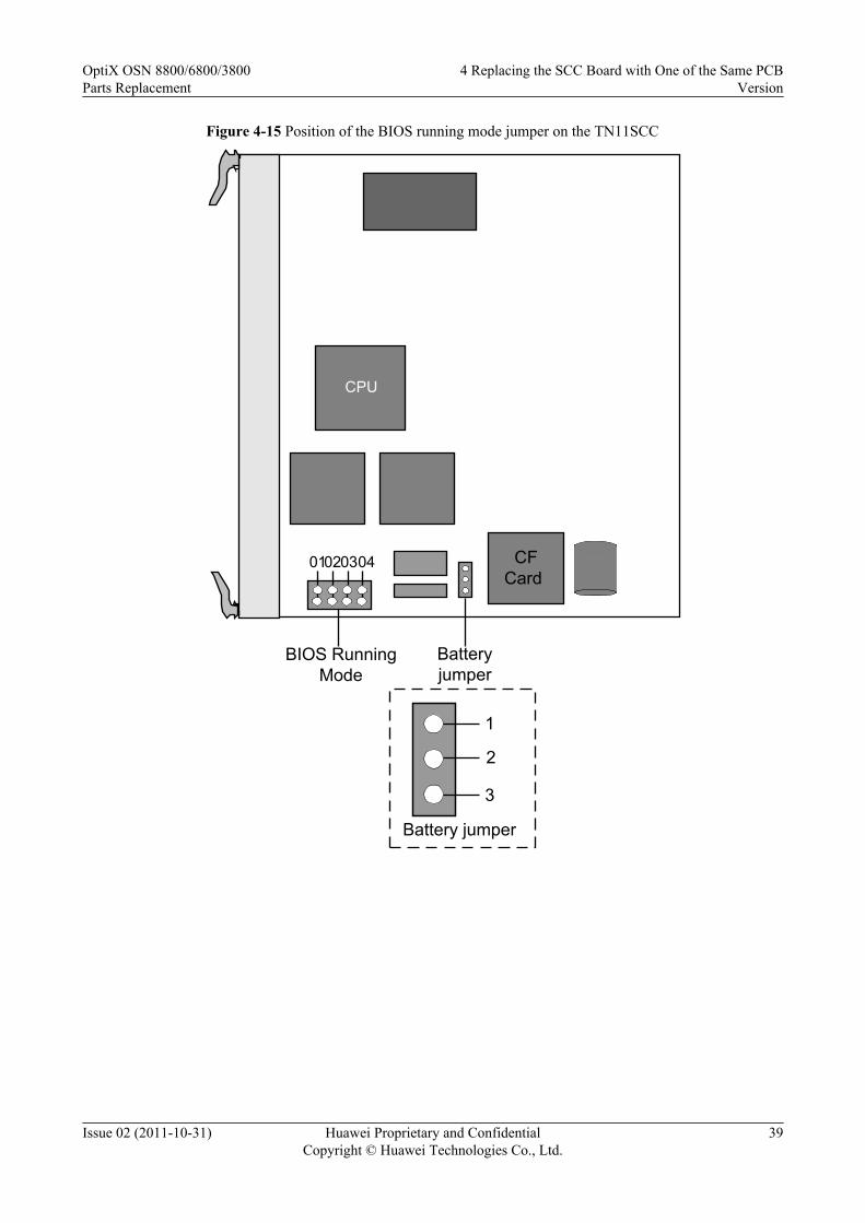
Figure 4-15 Position of the BIOS running mode jumper on the TN11SCC
CPU
Battery jumper
CFCard
1
2
3
Battery jumper
01020304
BIOS Running Mode
OptiX OSN 8800/6800/3800Parts Replacement
4 Replacing the SCC Board with One of the Same PCBVersion
Issue 02 (2011-10-31) Huawei Proprietary and ConfidentialCopyright © Huawei Technologies Co., Ltd.
39

Figure 4-16 Position of the BIOS running mode jumper on the TN16SCC
CF Card
Battery Jumper
3 2 1
J1SW1
OFF
ON
431 2
BIOS Running
Mode
OptiX OSN 8800/6800/3800Parts Replacement
4 Replacing the SCC Board with One of the Same PCBVersion
Issue 02 (2011-10-31) Huawei Proprietary and ConfidentialCopyright © Huawei Technologies Co., Ltd.
40

Figure 4-17 Position of the BIOS running mode jumper on the TN21/TN22SCC
CPU
Battery jumper
1
2
3
Battery jumper
J13J14
BIOS Running Mode
TN21SCC
CPU
Battery jumper
1
2
3
Battery jumper
J11J13
BIOS Running Mode
TN22SCC
OptiX OSN 8800/6800/3800Parts Replacement
4 Replacing the SCC Board with One of the Same PCBVersion
Issue 02 (2011-10-31) Huawei Proprietary and ConfidentialCopyright © Huawei Technologies Co., Ltd.
41
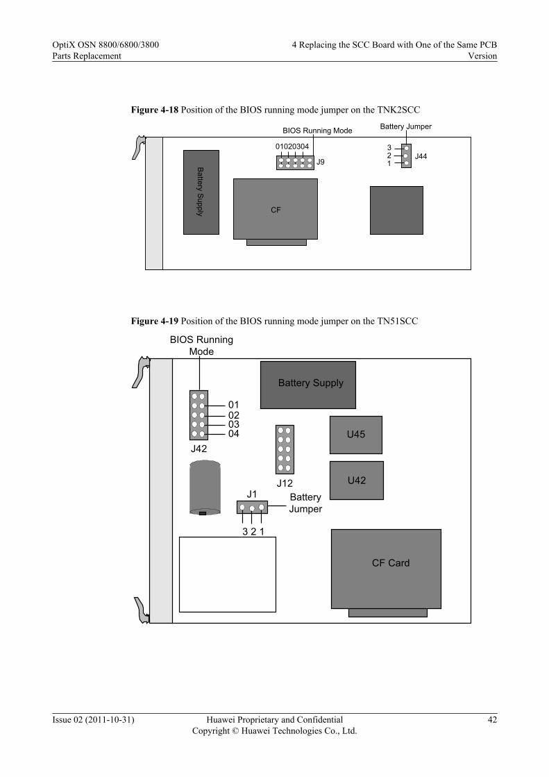
Figure 4-18 Position of the BIOS running mode jumper on the TNK2SCC
J44
Battery Jumper
CPU
3 21B
attery Supply CF
J9
01020304
BIOS Running Mode
Figure 4-19 Position of the BIOS running mode jumper on the TN51SCC
Battery Supply
U42J12
J42
3 2 1CPU
J1
U45
CF Card
Battery Jumper
BIOS Running Mode
01020304
OptiX OSN 8800/6800/3800Parts Replacement
4 Replacing the SCC Board with One of the Same PCBVersion
Issue 02 (2011-10-31) Huawei Proprietary and ConfidentialCopyright © Huawei Technologies Co., Ltd.
42
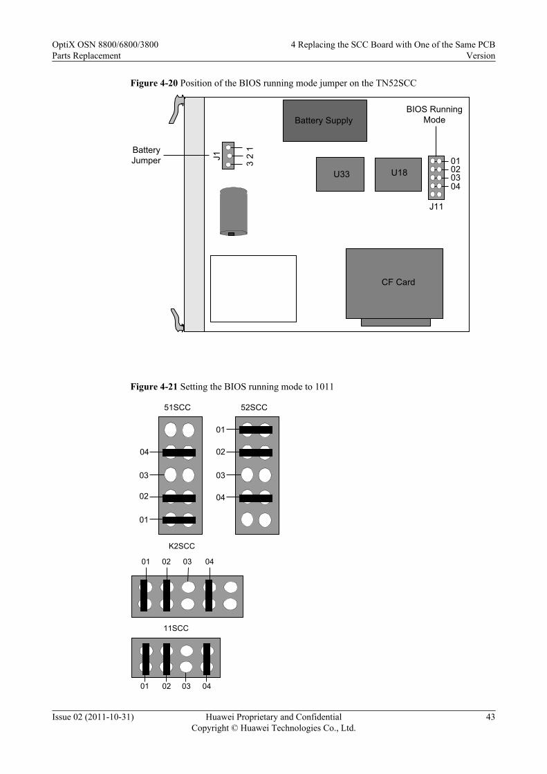
Figure 4-20 Position of the BIOS running mode jumper on the TN52SCC
Battery Supply
U33 U18
CF Card
Jumper 3 2
1C
PU
J1
Battery
J11
01020304
BIOS Running Mode
Figure 4-21 Setting the BIOS running mode to 1011
01
02
03
04
52SCC
02
03
04
51SCC
01
01 02 03 04
K2SCC
0401 02 03
11SCC
OptiX OSN 8800/6800/3800Parts Replacement
4 Replacing the SCC Board with One of the Same PCBVersion
Issue 02 (2011-10-31) Huawei Proprietary and ConfidentialCopyright © Huawei Technologies Co., Ltd.
43
ON
OFF
1 2 43
The Lowest Site
The Highest Site
ON=1
OFF=0
16SCC
0102
J13 J14
0304
TN21SCC
0102
J11
J130304
TN22SCC
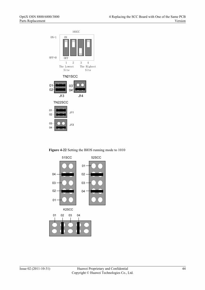
Figure 4-22 Setting the BIOS running mode to 1010
01
02
03
04
52SCC
01
02
03
04
51SCC
01 02 03 04
K2SCC
OptiX OSN 8800/6800/3800Parts Replacement
4 Replacing the SCC Board with One of the Same PCBVersion
Issue 02 (2011-10-31) Huawei Proprietary and ConfidentialCopyright © Huawei Technologies Co., Ltd.
44
0401 02 03
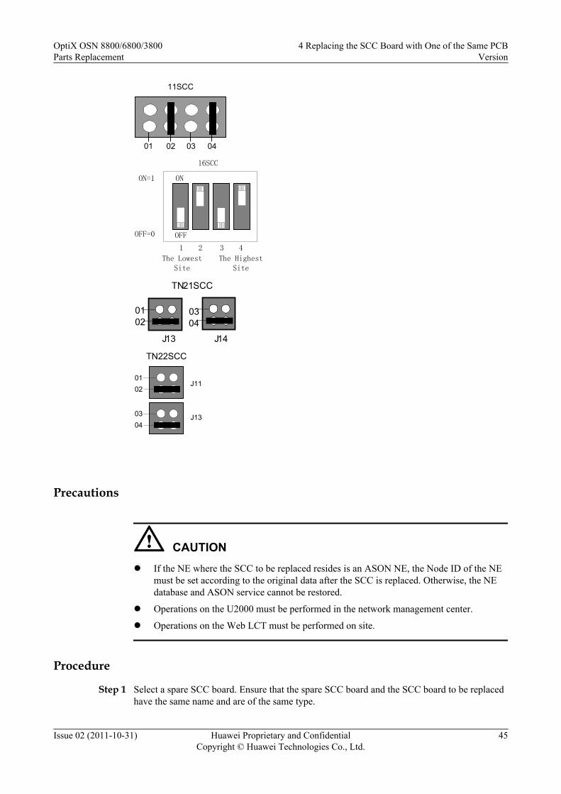
11SCC
ON
OFF
1 2 43
The Lowest Site
The Highest Site
ON=1
OFF=0
16SCC
0102
J13 J14
0304
TN21SCC
0102
J11
J130304
TN22SCC
Precautions
CAUTIONl If the NE where the SCC to be replaced resides is an ASON NE, the Node ID of the NE
must be set according to the original data after the SCC is replaced. Otherwise, the NEdatabase and ASON service cannot be restored.
l Operations on the U2000 must be performed in the network management center.
l Operations on the Web LCT must be performed on site.
Procedure
Step 1 Select a spare SCC board. Ensure that the spare SCC board and the SCC board to be replacedhave the same name and are of the same type.
OptiX OSN 8800/6800/3800Parts Replacement
4 Replacing the SCC Board with One of the Same PCBVersion
Issue 02 (2011-10-31) Huawei Proprietary and ConfidentialCopyright © Huawei Technologies Co., Ltd.
45
NOTEThe 1X3 jumper on the replacement board enables or disables the power supply from the battery. Ensurethat pin 1 and pin 2 of each jumper are capped. Then, remove the cap of pin 1 and cap pin 3 on the jumperand use a multimeter to measure the battery voltage. If the voltage is lower than 3 V, the battery is notworking. The selected SCC board cannot be used as a replacement.
Step 2 Inform the onsite maintenance engineer and remove the board. For details about how to removea board, see "Replacing a Board" of the Supporting Tasks.
Step 3 Set the jumpers on the spare SCC board. Insert the spare SCC board into the slot housing theoriginal SCC board. After you install the board, the database on the new SCC board is cleared.1. Set the BIOS running mode of the spare SCC board to 1011 to clear the database in the
flash memory. Figure 4-21 shows the settings of the four jumpers on the SCC board.2. Insert the spare SCC board in the slot housing the original SCC board.3. Wait for a few minutes until the PROG indicator is green and slowly flashes. Remove the
spare SCC board and then set its BIOS running mode to 1010 to clear the system parameterarea. For the settings of the four jumpers on the SCC board, see Figure 4-22. After that,reinsert the new SCC board to the slot.
NOTE
After the four jumpers are set and the SCC board is inserted in the slot, the PROG indicator on the SCCboard is constantly green, which indicates that the database is being cleared. Wait for a few minutes untilthe PROG indicator blinks green, which indicates that the database is cleared completely.
Step 4 After the database of the SCC board is cleared completely, remove the board. Remove the jumpercaps which are shown in Step 3. After that, reinsert this SCC board to the slot.
Step 5 After the new SCC board starts, connect the Web LCT to the NE. Modify the NE attribute torestore the communication between the NE and the U2000.1. Disconnect the cables from the NM_ETH1 and NM_ETH2 ports (if connected). That is,
disconnect the NE from the computer where the U2000 (hereinafter the computer is referredto as U2000) is installed.
2. Connect the Web LCT to NM_ETH1.3. Set the IP address of the Web LCT to ensure that Web LCT is in the same IP subnet segment
as the NE IP address. If the IP address of the Web LCT and the NE IP address are in differentnetwork segments, the Web LCT cannot be connected to the NE.
NOTEThe new board is initiated at factory, and the default IP subnet segment of the board is 129.9.*.*.
4. Log in to the Web LCT with the user name admin, and the initial password admin.
Step 6 Create the NE by using the Web LCT.
1. Click NE Search > Advanced Search in the NE List. The Search NE dialog box isdisplayed.
2. Click Manage Domain. The Manage Domain Search dialog box is displayed.3. Click Add, and the New Domain dialog box is displayed.4. Set Domain Type to GNE IP Domain or GNE IP Address, and enter an IP address in the
Domain Address field.5. Click OK.
NOTEYou can repeat step 3 through 5 to add multiple search domains.
6. Click Cancel to exit the Manage Domain Search dialog box.
OptiX OSN 8800/6800/3800Parts Replacement
4 Replacing the SCC Board with One of the Same PCBVersion
Issue 02 (2011-10-31) Huawei Proprietary and ConfidentialCopyright © Huawei Technologies Co., Ltd.
46
7. Select appropriate network segment IP addresses within the Domain and click Search.
NOTE
l The NE search function searches out only the NEs in the specified network segment.
l When the search is in progress, you can click End Search.
8. After the search is complete, select an NE from the list and click Add NE. A promptmessage is displayed, indicating that the NE is successfully added. Click OK.
9. Select the NE that you want to log in and click NE Login in the lower right corner or right-click the NE and choose NE Login. In the NE Login dialog box that is displayed, enterlct and password in the User Name and Password fields, and then click OK.
TIP
You can select multiple NEs at a time by concurrently pressing Shift.
If you select the Use same user name and password to login check box, you can log in to multipleNEs at a time by entering the user name and password only in the first line.
If you select the Use the user name and password that was used last time check box, you do notneed to enter the use name and password and the system automatically uses the user name andpassword for login last time.
Step 7 Modify the NE IP based on the original information by using the Web LCT.
1. In the NE Explorer, select Communication > Communication Parameters fromFunction Tree.
2. Enter the IP Address, and click Apply.3. Click OK after the warning dialog box pops up.4. Click OK after the warning dialog box about communication interruption between NEs
pops up.5. Click Close after the Result dialog box is displayed.
NOTEIf the NE IP addresses before and after the modification are in different network segments, the Web LCT cannotbe connected to the NE. When this occurs, set the IP address of the Web LCT in the same network segment asthe NE IP address.
Step 8 Modify the gateway IP based on the original information by using the Web LCT.
1. In the NE Explorer, Select Communication > Communication Parameters fromFunction Tree.
2. Enter the Gateway IP Address, and click Apply.3. Click OK after the Warning dialogue box pops up that prompts "The NE communication
parameters have been changed. Are you sure to send it? ".4. Click OK after the Warning dialogue box pops up that prompts "Incorrect operations will
interrupt the communication between NEs. Are you sure to continue? ".
Step 9 Modify the subnet mask based on the original information by using the Web LCT.
1. In the NE Explorer, Select Communication > Communication Parameters fromFunction Tree.
2. Enter the Subnet Mask, and click Apply.3. Click OK after the Warning dialogue box pops up that prompts "The NE communication
parameters have been changed. Are you sure to send it? ".4. Click OK after the Warning dialogue box pops up that prompts "Incorrect operations will
interrupt the communication between NEs. Are you sure to continue? ".
OptiX OSN 8800/6800/3800Parts Replacement
4 Replacing the SCC Board with One of the Same PCBVersion
Issue 02 (2011-10-31) Huawei Proprietary and ConfidentialCopyright © Huawei Technologies Co., Ltd.
47
Step 10 Modify the NE ID and extended ID based on the original information by using the Web LCT.
1. In the NE Explorer, choose Configuration > NE Attribute from the Function Tree.2. Click Modify NE ID. In the Modify NE ID dialog box that is displayed, enter values in
the New ID and New Extended ID fields, and then click OK.3. A warning dialog box is displayed, click Yes. A dialog box indicating that the operation is
successful is displayed, click Close to complete changing the NE ID. At this time, the NEis unreachable.
Step 11 Check the NE communication parameters by using the Web LCT.
1. Select the NE you just created, and click the NE Explorer.2. Select Communication > Communication Parameters from Function Tree.3. Check that all NE communication parameters should be the same with the original ones.
Step 12 Create an NE's user by using the Web LCT.
1. In the NE Explorer, select the NE and choose Security > NE User Management from theFunction Tree.
2. Click Create and the Add NE User dialog box is displayed.3. Enter the NE user name in the NE User field.4. Select the User Level as needed.5. Enter the password in the New Password field and enter it again in the Confirm
Password field.
NOTE
You also need to set the Whether the password is allowed to be modified immediately parameter.
The password is a string of 6-16 characters. It can consist of letters, symbols and numerals, and mustcontain at least one letter and one numeral.
6. Click OK.7. Click Query, and the Operation Result dialog box is displayed. Click Close. All created
users of the NE are displayed in NE User Management Table.
Step 13 If the NE is an ASON NE, modify the node ID of the NE by using the Web LCT.
1. In the NE Explorer, select an NE and choose ASON > ASON Feature Management fromthe Function Tree. Click the Node ID Management tab.
2. Click Query to view the current node ID of the NE.3. Double-click the Node ID field to enter a node ID for the NE.4. Click Apply. After you confirm the operation twice, a prompt appears telling you that the
operation was successful.
NOTE
You can also choose Configuration > WDM ASON > ASON Topology Management from the mainmenu and set the NE node ID.
Step 14 Recover the network connection of the NE.1. Remove the network cable which connected the NM_ETH1 port to the Web LCT.2. Connect the network cable removed in the Step 5.
NOTEAfter this procedure, you can use the original user name and password to access the NE by using theU2000.
OptiX OSN 8800/6800/3800Parts Replacement
4 Replacing the SCC Board with One of the Same PCBVersion
Issue 02 (2011-10-31) Huawei Proprietary and ConfidentialCopyright © Huawei Technologies Co., Ltd.
48

Step 15 If the software version of the spare SCC board is different from the software version of the SCCboard to be replaced, go to Step 16, otherwise go to Step 17.
Step 16 Upgrade or downgrade the software of the spare SCC board. For details, see the UpgradeGuide. Ensure that the software version of the spare SCC board is consistent with that of theSCC board to be replaced.
Step 17 Restore the NE database from the NMS server.
1. In the Main Topology view, choose Administration > NE Software Management > NEData Backup/Restoration from the Main Menu.
2. Right click the device(s) that you want to recover in the NE View table.
3. Select Recover... to open the Recover dialog.
4. In the File Name drop-down list, select the file to be recovered. If the backup file is notlisted in the File Name drop-down list, select the file to be recovered, and turn to 17.6. Ifthe backup file is not listed in the File Name drop-down list, click Browse... to select thebackup file in the Select File dialog box, as shown below.
5. Select NMS Server or NMS Client to recover the backup file for the selected device(s).By default NMS Server is selected.
l If NMS Server is selected, you need to select the appropriate backup file from the NMSserver. The selected backup file path is displayed in the File To Be Recovered field.
l If NMS Client is selected, you need to click to select the backup file from theNMS Client. The selected backup file path is displayed in the File To Be Recoveredfield.
6. Click OK.
NOTE
The selected backup file path from the NMS Server or NMS Client is displayed in the File Name drop-down list.
7. Click Start, the Operation Confirmation dialog box is displayed.
8. In the Operation Confirmation dialog, click Yes to start the recover operation. Therecover operation status is displayed in the NE View table.
NOTE
You must activate the NE database within five minutes after restoring it.
CAUTIONDuring the process from backing up databases to restoring databases, do not modify the NEconfigurations to avoid database inconsistency.
Step 18 Activate the NE database.
1. In the Main Topology view, choose Administration > NE Software Management > NEData Backup/Restoration from the Main Menu.
2. Select the NE where the SCC that has been replaced resides in the NE View table.
3. Right-click the NE, a pop-up menu is displayed.
4. Select Activate Database..., and the Activate Database dialog box is displayed.
OptiX OSN 8800/6800/3800Parts Replacement
4 Replacing the SCC Board with One of the Same PCBVersion
Issue 02 (2011-10-31) Huawei Proprietary and ConfidentialCopyright © Huawei Technologies Co., Ltd.
49

5. Optional: Click the icon in Deliver To Board Activate, and then this icon is changedto . Click Start to start the database activation process. The progress of the databaseactivation is displayed on the NE View tab.
NOTE
The operation on the U2000 may bring a service interruption.
Step 19 Check and set the other parameters on the U2000 to ensure that the parameter values of the newboard are the same as the original data.1. Check the software information of the new SCC against the original data.2. Synchronize the NE time with the NMS server time.3. Check the NE alarm attribute data against the original data. The data include saving mode,
reversion mode and delayed report.4. Check the alarm suppression setting data against the original data.5. Enable the NE performance monitoring.6. Configure the OSPF IP address of the NE if the site complies with the models for separated
optical and electrical NEs and the NE is on an optical-layer ASON network.
NOTEFor details to set these parameters, see iManager U2000 Operator Guide for NG WDM NE Management.
Step 20 Querying the current alarms of the NE by using the U2000.
1. In the Main Topology view, choose Fault > Browse Current Alarm from the Main Menu.2. Click the Basic Setting and Alarm Source tabs in turn on the Filter dialog box to set the
filter conditions for the current alarms.3. Click OK.4. Record the current alarms of the NE.
NOTEYou can select the desired alarms and right-click to choose Save > Save Selected Records, or right-click to choose Save > Save All Records from the shortcut menu to save the current alarms of theNE.
NOTEAfter replacing the SCC is replaced, ensure that the monitoring of the POWER_FAIL alarm is enabled. Ifthe POWER_FAIL alarm occurs, and the alarm parameter is 0x5 0xff 0xff 0xff 0xff, the battery of the SCCboard is abnormal, check whether the jumper cap is correctly placed over the battery jumper. If yes, use amultimeter to measure the battery voltage. If the voltage is lower than 3 V, the battery is out of work. Theboard must be replaced.
CAUTIONThe standard voltage of the battery is 3.6 V. The battery is fixed on the board and cannot bereplaced.
----End
OptiX OSN 8800/6800/3800Parts Replacement
4 Replacing the SCC Board with One of the Same PCBVersion
Issue 02 (2011-10-31) Huawei Proprietary and ConfidentialCopyright © Huawei Technologies Co., Ltd.
50

4.3.2 Replacing the SCC Board with the Database Backed Up to aCF Card (NE Is Unreachable)
When the NE is unreachable resulting from a damage of the SCC board, restore the NE databasefrom the CF card after replacing the SCC board if there is no backup data on the NMS.
PrerequisiteYou must be an NM user with "NE and network operator" authority or higher.
The SCC replacement board must be the same type as the SCC board being replaced.
Impact on SystemReplacing the SCC board does not affect traditional services, but ASON services may be affectedfor a short time when configurations are restored by downloading the database.
Tools, Equipment, and MaterialsESD bag, U2000, multimeter, Web LCT
Background InformationBefore replacing an SCC board with a spare SCC board, set the battery jumper on the spare SCCboard with reference to 4.1 Setting the Battery Jumper on the SCC.
You must clear the database on the spare SCC board before replacing the replacement board.You can clear the database by setting the BIOS running mode by using four jumpers on thereplacement SCC board. The figure below shows the four jumpers for setting the BIOS runningmode and the battery jumper on an SCC board. The four jumpers for setting the BIOS runningmode are arranged from high order to low order and identified as 04, 03, 02, and 01.
The setting of each of the four jumpers corresponds to a binary value, either 0 or 1. When ajumper is not capped, the setting corresponds to binary 0. When a jumper is capped, the settingcorresponds to binary 1. The settings of the four jumpers can be arranged in 16 combinations,representing 0 to 15 in the decimal system. The default setting of the four jumpers is 0000.
OptiX OSN 8800/6800/3800Parts Replacement
4 Replacing the SCC Board with One of the Same PCBVersion
Issue 02 (2011-10-31) Huawei Proprietary and ConfidentialCopyright © Huawei Technologies Co., Ltd.
51

Figure 4-23 Position of the BIOS running mode jumper on the TN11SCC
CPU
Battery jumper
CFCard
1
2
3
Battery jumper
01020304
BIOS Running Mode
OptiX OSN 8800/6800/3800Parts Replacement
4 Replacing the SCC Board with One of the Same PCBVersion
Issue 02 (2011-10-31) Huawei Proprietary and ConfidentialCopyright © Huawei Technologies Co., Ltd.
52

Figure 4-24 Position of the BIOS running mode jumper on the TN16SCC
CF Card
Battery Jumper
3 2 1
J1SW1
OFF
ON
431 2
BIOS Running
Mode
Figure 4-25 Position of the BIOS running mode jumper on the TNK2SCC
J44
Battery Jumper
CPU
3 21B
attery Supply CF
J9
01020304
BIOS Running Mode
OptiX OSN 8800/6800/3800Parts Replacement
4 Replacing the SCC Board with One of the Same PCBVersion
Issue 02 (2011-10-31) Huawei Proprietary and ConfidentialCopyright © Huawei Technologies Co., Ltd.
53

Figure 4-26 Position of the BIOS running mode jumper on the TN51SCC
Battery Supply
U42J12
J42
3 2 1CPU
J1
U45
CF Card
Battery Jumper
BIOS Running Mode
01020304
Figure 4-27 Position of the BIOS running mode jumper on the TN52SCC
Battery Supply
U33 U18
CF Card
Jumper 3 2
1C
PU
J1
Battery
J11
01020304
BIOS Running Mode
OptiX OSN 8800/6800/3800Parts Replacement
4 Replacing the SCC Board with One of the Same PCBVersion
Issue 02 (2011-10-31) Huawei Proprietary and ConfidentialCopyright © Huawei Technologies Co., Ltd.
54

Figure 4-28 Setting the BIOS running mode to 1011
01
02
03
04
52SCC
02
03
04
51SCC
01
01 02 03 04
K2SCC
0401 02 03
11SCC
ON
OFF
1 2 43
The Lowest Site
The Highest Site
ON=1
OFF=0
16SCC
OptiX OSN 8800/6800/3800Parts Replacement
4 Replacing the SCC Board with One of the Same PCBVersion
Issue 02 (2011-10-31) Huawei Proprietary and ConfidentialCopyright © Huawei Technologies Co., Ltd.
55

Figure 4-29 Setting the BIOS running mode to 1010
01
02
03
04
52SCC
01
02
03
04
51SCC
01 02 03 04
K2SCC
0401 02 03
11SCC
ON
OFF
1 2 43
The Lowest Site
The Highest Site
ON=1
OFF=0
16SCC
OptiX OSN 8800/6800/3800Parts Replacement
4 Replacing the SCC Board with One of the Same PCBVersion
Issue 02 (2011-10-31) Huawei Proprietary and ConfidentialCopyright © Huawei Technologies Co., Ltd.
56

Precautions
CAUTIONl If the NE where the SCC to be replaced resides is an ASON NE, the Node ID of the NE must
be set according to the original data after the SCC is replaced. Otherwise, the ASON servicecannot be restored.
l After the database of the NE is restored on the CF card, the restoration must be completedwithin two hours after you install the replacement SCC is installed. If you wait more thantwo hours to restore the database of the NE on the CF card, the data automatically saved onthe NE overwrites the original data stored on the CF card. If the original data is overwritten,the original database of the NE cannot be restored.
l Operations on the U2000 must be performed in the network management center.
l Operations on the Web LCT must be performed on site.
Procedure
Step 1 Select a spare SCC board as the replacement board. Ensure that the spare SCC board and theSCC board to be replaced have the same name and are of the same type.
NOTEThe 1X3 jumper (namely, the battery jumper) on the board is used to enable or disable the power supplyfrom the battery. Make sure that pin 1 and pin 2 of each jumper are capped. Then, cap pin 2 and pin 3 onthe jumper and use a multimeter to measure the battery voltage. If the voltage is lower than 3 V, the batteryis not working. The board must be replaced.
Step 2 Remove the SCC board to be replaced. For more information, see "Replacing a Board" of theSupporting Tasks.
Step 3 On the SCC board that has been removed, hold the CF card and pull the card out of the CF cardslot. Put the SCC into an ESD bag.
NOTE
Keep the CF card because it is required for NE data restoration.
Step 4 Set the four jumpers on the spare SCC board so as to set the BIOS running mode of the SCCboard and then insert it to the slot housing the original SCC board. In this manner, the databaseon the new SCC board is cleared.
1. Set the BIOS running mode of the spare SCC board to 1011 to clear the database in theflash memory. Figure 4-28 shows the settings of the four jumpers on the SCC board.
2. Insert the spare SCC board to the slot housing the original SCC board.
3. Wait for a few minutes until the PROG indicator is green and slowly flashes. Remove thespare SCC board and then set its BIOS running mode to 1010 to clear the system parameterarea. For the settings of the four jumpers on the SCC board, see Figure 4-29. After that,reinsert the new SCC board to the slot.
NOTE
After the four BIOS jumpers are set and you install the SCC board in the slot, the PROG indicator on theSCC board is constantly green, which indicates that the database is being cleared. Wait for a few minutesuntil the PROG indicator blinks green, which indicates that the database is cleared completely.
OptiX OSN 8800/6800/3800Parts Replacement
4 Replacing the SCC Board with One of the Same PCBVersion
Issue 02 (2011-10-31) Huawei Proprietary and ConfidentialCopyright © Huawei Technologies Co., Ltd.
57
Step 5 After the database of the SCC board is cleared completely, remove the board. Remove the jumpercaps which are shown in Step 4. After that, reinsert this SCC board to the slot.
Step 6 After the new SCC board is started, connect the Web LCT to the NE. Modify the NE attributeto restore the communication between the NE and the U2000.1. Disconnect the cables from the NM_ETH1 and NM_ETH2 ports (if connected). That is,
disconnect the NE from the computer where the U2000 (hereinafter the computer is referredto as U2000) is installed.
2. Connect the Web LCT to NM_ETH1.3. Set the IP address of the Web LCT to ensure that Web LCT is in the same IP subnet segment
as the NE IP address. If the IP address of the Web LCT and the NE IP address are in differentnetwork segments, the Web LCT cannot be connected to the NE.
NOTEThe new board is initiated at factory, and the default IP subnet segment of the board is 129.9.*.*.
4. Log in the Web LCT with the user name admin, and the initial password admin.
Step 7 Create the NE by using the Web LCT.
1. Click NE Search > Advanced Search in the NE List. The Search NE dialog box isdisplayed.
2. Click Manage Domain. The Manage Domain Search dialog box is displayed.3. Click Add, and the New Domain dialog box is displayed.4. Set Domain Type to GNE IP Domain or GNE IP Address, and enter an IP address in the
Domain Address field.5. Click OK.
NOTEYou can repeat step 3 through 5 to add multiple search domains.
6. Click Cancel to exit the Manage Domain Search dialog box.7. Select appropriate network segment IP addresses within the Domain and click Search.
NOTE
l The NE search function searches out only the NEs in the specified network segment.
l When the search is in progress, you can click End Search.
8. After the search is complete, select an NE from the list and click Add NE. A promptmessage is displayed, indicating that the NE is successfully added. Click OK.
9. Select the NE that you want to log in and click NE Login in the lower right corner or right-click the NE and choose NE Login. In the NE Login dialog box that is displayed, enterlct and password in the User Name and Password fields, and then click OK.
TIP
You can select multiple NEs at a time by concurrently pressing Shift.
If you select the Use same user name and password to login check box, you can log in to multipleNEs at a time by entering the user name and password only in the first line.
If you select the Use the user name and password that was used last time check box, you do notneed to enter the use name and password and the system automatically uses the user name andpassword for login last time.
Step 8 Modify the NE IP based on the original information by using the Web LCT.
1. In the NE Explorer, select Communication > Communication Parameters fromFunction Tree.
OptiX OSN 8800/6800/3800Parts Replacement
4 Replacing the SCC Board with One of the Same PCBVersion
Issue 02 (2011-10-31) Huawei Proprietary and ConfidentialCopyright © Huawei Technologies Co., Ltd.
58

2. Enter the IP Address, and click Apply.3. Click OK after the warning dialog box pops up.4. Click OK after the warning dialog box about communication interruption between NEs
pops up.5. Click Close after the Result dialog box is displayed.
NOTEIf the NE IP addresses before and after the modification are in different network segments, the Web LCT cannotbe connected to the NE. When this occurs, set the IP address of the Web LCT in the same network segment asthe NE IP address.
Step 9 Modify the gateway IP based on the original information by using the Web LCT.
1. In the NE Explorer, Select Communication > Communication Parameters fromFunction Tree.
2. Enter the Gateway IP Address, and click Apply.3. Click OK after the Warning dialogue box pops up that prompts "The NE communication
parameters have been changed. Are you sure to send it? ".4. Click OK after the Warning dialogue box pops up that prompts "Incorrect operations will
interrupt the communication between NEs. Are you sure to continue? ".
Step 10 Modify the subnet mask based on the original information by using the Web LCT.
1. In the NE Explorer, Select Communication > Communication Parameters fromFunction Tree.
2. Enter the Subnet Mask, and click Apply.3. Click OK after the Warning dialogue box pops up that prompts "The NE communication
parameters have been changed. Are you sure to send it? ".4. Click OK after the Warning dialogue box pops up that prompts "Incorrect operations will
interrupt the communication between NEs. Are you sure to continue? ".
Step 11 Modify the NE ID and extended ID based on the original information by using the Web LCT.
1. In the NE Explorer, choose Configuration > NE Attribute from the Function Tree.2. Click Modify NE ID. In the Modify NE ID dialog box that is displayed, enter values in
the New ID and New Extended ID fields, and then click OK.3. A warning dialog box is displayed, click Yes. A dialog box indicating that the operation is
successful is displayed, click Close to complete changing the NE ID. At this time, the NEis unreachable.
Step 12 Check the NE communication parameters by using the Web LCT.
1. Select the NE you just created, and click the NE Explorer.2. Select Communication > Communication Parameters from Function Tree.3. Check that all NE communication parameters should be the same with the original ones.
Step 13 Create an NE's user by using the Web LCT.
1. In the NE Explorer, select the NE and choose Security > NE User Management from theFunction Tree.
2. Click Create and the Add NE User dialog box is displayed.3. Enter the NE user name in the NE User field.4. Select the User Level as needed.
OptiX OSN 8800/6800/3800Parts Replacement
4 Replacing the SCC Board with One of the Same PCBVersion
Issue 02 (2011-10-31) Huawei Proprietary and ConfidentialCopyright © Huawei Technologies Co., Ltd.
59
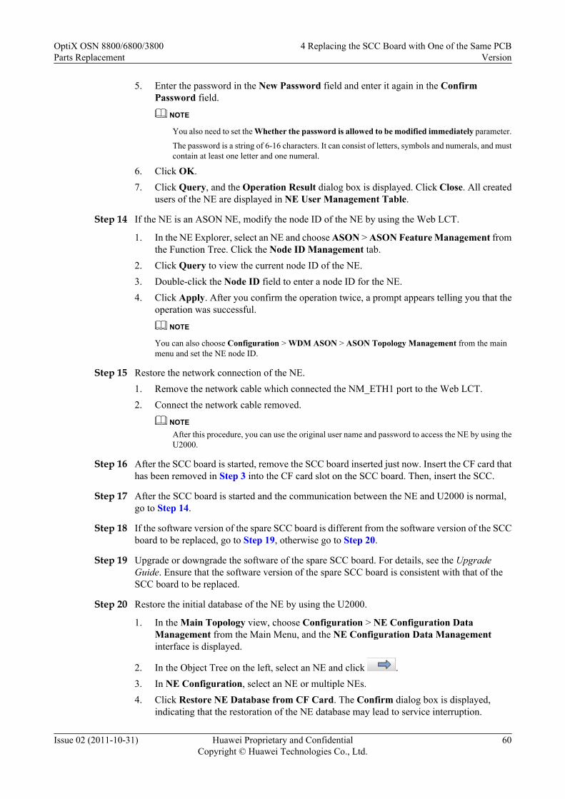
5. Enter the password in the New Password field and enter it again in the ConfirmPassword field.
NOTE
You also need to set the Whether the password is allowed to be modified immediately parameter.
The password is a string of 6-16 characters. It can consist of letters, symbols and numerals, and mustcontain at least one letter and one numeral.
6. Click OK.7. Click Query, and the Operation Result dialog box is displayed. Click Close. All created
users of the NE are displayed in NE User Management Table.
Step 14 If the NE is an ASON NE, modify the node ID of the NE by using the Web LCT.
1. In the NE Explorer, select an NE and choose ASON > ASON Feature Management fromthe Function Tree. Click the Node ID Management tab.
2. Click Query to view the current node ID of the NE.3. Double-click the Node ID field to enter a node ID for the NE.4. Click Apply. After you confirm the operation twice, a prompt appears telling you that the
operation was successful.
NOTE
You can also choose Configuration > WDM ASON > ASON Topology Management from the mainmenu and set the NE node ID.
Step 15 Restore the network connection of the NE.1. Remove the network cable which connected the NM_ETH1 port to the Web LCT.2. Connect the network cable removed.
NOTEAfter this procedure, you can use the original user name and password to access the NE by using theU2000.
Step 16 After the SCC board is started, remove the SCC board inserted just now. Insert the CF card thathas been removed in Step 3 into the CF card slot on the SCC board. Then, insert the SCC.
Step 17 After the SCC board is started and the communication between the NE and U2000 is normal,go to Step 14.
Step 18 If the software version of the spare SCC board is different from the software version of the SCCboard to be replaced, go to Step 19, otherwise go to Step 20.
Step 19 Upgrade or downgrade the software of the spare SCC board. For details, see the UpgradeGuide. Ensure that the software version of the spare SCC board is consistent with that of theSCC board to be replaced.
Step 20 Restore the initial database of the NE by using the U2000.
1. In the Main Topology view, choose Configuration > NE Configuration DataManagement from the Main Menu, and the NE Configuration Data Managementinterface is displayed.
2. In the Object Tree on the left, select an NE and click .3. In NE Configuration, select an NE or multiple NEs.4. Click Restore NE Database from CF Card. The Confirm dialog box is displayed,
indicating that the restoration of the NE database may lead to service interruption.
OptiX OSN 8800/6800/3800Parts Replacement
4 Replacing the SCC Board with One of the Same PCBVersion
Issue 02 (2011-10-31) Huawei Proprietary and ConfidentialCopyright © Huawei Technologies Co., Ltd.
60

5. Click OK to start to restore the NE database.6. Click Closeafter an Operation Result dialog box is displayed.
NOTEAfter the NE databases are restored, the NE software issues the data in the CF card to only the SCC boardbut not other boards. To ensure that the configurations in the SCC board and the configurations in otherboards are consistent, you need to perform warm resets on other boards.
CAUTIONDuring the process from backing up databases to restoring databases, do not modify the NEconfigurations to avoid database inconsistency.
Step 21 Check and set the other parameters on the U2000 to ensure that the parameter values of the newboard are the same as the original data.1. Check the software information of the new SCC against the original data.2. Synchronize the NE time with the NMS server time.3. Check the NE alarm attribute data against the original data. The data include saving mode,
reversion mode and delayed report.4. Check the alarm suppression setting data against the original data.5. Enable the NE performance monitoring.6. Configure the OSPF IP address of the NE if the site complies with the models for separated
optical and electrical NEs and the NE is on an optical-layer ASON network.
NOTEFor details to set these parameters, see iManager U2000 Operator Guide for NG WDM NE Management.
Step 22 Querying the current alarms of the NE by using the U2000.
1. In the Main Topology view, choose Fault > Browse Current Alarm from the Main Menu.2. Click the Basic Setting and Alarm Source tabs in turn on the Filter dialog box to set the
filter conditions for the current alarms.3. Click OK.4. Record the current alarms of the NE.
NOTEYou can select the desired alarms and right-click to choose Save > Save Selected Records, or right-click to choose Save > Save All Records from the shortcut menu to save the current alarms of theNE.
NOTEAfter replacing the SCC is replaced, ensure that the monitoring of the POWER_FAIL alarm is enabled. Ifthe POWER_FAIL alarm occurs, and the alarm parameter is 0x5 0xff 0xff 0xff 0xff, the battery of the SCCboard is abnormal, check whether the jumper cap is correctly placed over the battery jumper. If yes, use amultimeter to measure the battery voltage. If the voltage is lower than 3 V, the battery is out of work. Theboard must be replaced.
OptiX OSN 8800/6800/3800Parts Replacement
4 Replacing the SCC Board with One of the Same PCBVersion
Issue 02 (2011-10-31) Huawei Proprietary and ConfidentialCopyright © Huawei Technologies Co., Ltd.
61

CAUTIONThe standard voltage of the battery is 3.6 V. The battery is fixed on the board and cannot bereplaced.
----End
4.3.3 Replacing the SCC Board After Configuring SCC 1+1Protection
When replacing an SCC board, you can configure protection for the SCC board if the NE isreachable and the slot for housing the standby SCC board is not occupied by a service board.
Prerequisitel You must be an NM user with "NE and network operator" authority or higher.l The FTP/TFTP/SFTP server is configured and the FTP/TFTP/SFTP service is started. For
more information, see U2000 NE Software Management.l The type of the replacement SCC board is the same of the SCC board to be replaced.
Impact on System
Replacing the SCC does not affect the existing services.
The impact caused by replacing an SCC without protection is as follows:
l For the OptiX OSN 8800 T16, the SCC is housed in IU9 by default. When IU10 is notoccupied by another board, it is available for another SCC to implement 1+1 protectionwith the SCC in IU9. In this case, replacing one of the SCC in the protection group doesnot interrupt the communication between the NE where the SCC resides and the U2000after a switching from this SCC to the other SCC is performed.
l For the OptiX OSN 8800 T32, the SCC is housed in IU28 by default. When IU11 is notoccupied by another board, it is available for another SCC to implement 1+1 protectionwith the SCC in IU28. In this case, replacing one of the SCC in the protection group doesnot interrupt the communication between the NE where the SCC resides and the U2000after a switching from this SCC to the other SCC is performed.
l For the OptiX OSN 8800 T64, the SCC is housed in IU74 by default. When IU85 is vacant,it is available for another SCC to implement 1+1 protection with the SCC in IU74. In thiscase, replacing one of the SCC in the protection group does not interrupt the communicationbetween the NE where the SCC resides and the U2000 after a switching from this SCC tothe other SCC is performed.
l For the OptiX OSN 6800, the SCC is housed in IU18 by default. When IU17 is not occupiedby another board, it is available for another SCC to implement 1+1 protection with the SCCin IU18. In this case, replacing one of the SCC in the protection group does not interruptthe communication between the NE where the SCC resides and the U2000 after a switchingfrom this SCC to the other SCC is performed.
l For the OptiX OSN 3800, the SCC is housed in IU9 by default. When IU8 is not occupiedby another board, it is available for another SCC to implement 1+1 protection with the SCCin IU9. In this case, replacing one of the SCC in the protection group does not interrupt the
OptiX OSN 8800/6800/3800Parts Replacement
4 Replacing the SCC Board with One of the Same PCBVersion
Issue 02 (2011-10-31) Huawei Proprietary and ConfidentialCopyright © Huawei Technologies Co., Ltd.
62

communication between the NE where the SCC resides and the U2000 after a switchingfrom this SCC to the other SCC is performed.
Tools, Equipment, and MaterialsESD bag, U2000, multimeter, Web LCT
Background InformationBefore replacing an SCC board with a spare SCC board, set the battery jumper on the spare SCCboard with reference to 4.1 Setting the Battery Jumper on the SCC.
You must clear the database on the spare SCC board before replacing the replacement board.You can clear the database by setting the BIOS running mode by using four jumpers on thereplacement SCC board. The figure below shows the four jumpers for setting the BIOS runningmode and the battery jumper on an SCC board. The four jumpers for setting the BIOS runningmode are arranged from high order to low order and identified as 04, 03, 02, and 01.
The setting of each of the four jumpers corresponds to a binary value, either 0 or 1. When ajumper is not capped, the setting corresponds to binary 0. When the jumper is capped, the settingcorresponds to binary 1. The settings of the four jumpers can be arranged in 16 combinations,representing 0 to 15 in the decimal system. The default setting of the four jumpers is 0000.
OptiX OSN 8800/6800/3800Parts Replacement
4 Replacing the SCC Board with One of the Same PCBVersion
Issue 02 (2011-10-31) Huawei Proprietary and ConfidentialCopyright © Huawei Technologies Co., Ltd.
63

Figure 4-30 Position of the BIOS running mode jumper on the TN11SCC
CPU
Battery jumper
CFCard
1
2
3
Battery jumper
01020304
BIOS Running Mode
OptiX OSN 8800/6800/3800Parts Replacement
4 Replacing the SCC Board with One of the Same PCBVersion
Issue 02 (2011-10-31) Huawei Proprietary and ConfidentialCopyright © Huawei Technologies Co., Ltd.
64
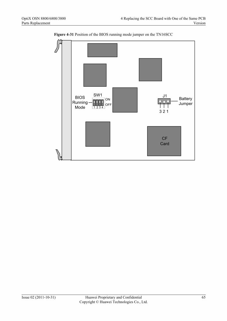
Figure 4-31 Position of the BIOS running mode jumper on the TN16SCC
CF Card
Battery Jumper
3 2 1
J1SW1
OFF
ON
431 2
BIOS Running
Mode
OptiX OSN 8800/6800/3800Parts Replacement
4 Replacing the SCC Board with One of the Same PCBVersion
Issue 02 (2011-10-31) Huawei Proprietary and ConfidentialCopyright © Huawei Technologies Co., Ltd.
65

Figure 4-32 Position of the BIOS running mode jumper on the TN21/TN22SCC
CPU
Battery jumper
1
2
3
Battery jumper
J13J14
BIOS Running Mode
TN21SCC
CPU
Battery jumper
1
2
3
Battery jumper
J11J13
BIOS Running Mode
TN22SCC
OptiX OSN 8800/6800/3800Parts Replacement
4 Replacing the SCC Board with One of the Same PCBVersion
Issue 02 (2011-10-31) Huawei Proprietary and ConfidentialCopyright © Huawei Technologies Co., Ltd.
66

Figure 4-33 Position of the BIOS running mode jumper on the TNK2SCC
J44
Battery Jumper
CPU
3 21B
attery Supply CF
J9
01020304
BIOS Running Mode
Figure 4-34 Position of the BIOS running mode jumper on the TN51SCC
Battery Supply
U42J12
J42
3 2 1CPU
J1
U45
CF Card
Battery Jumper
BIOS Running Mode
01020304
OptiX OSN 8800/6800/3800Parts Replacement
4 Replacing the SCC Board with One of the Same PCBVersion
Issue 02 (2011-10-31) Huawei Proprietary and ConfidentialCopyright © Huawei Technologies Co., Ltd.
67

Figure 4-35 Position of the BIOS running mode jumper on the TN52SCC
Battery Supply
U33 U18
CF Card
Jumper 3 2
1C
PU
J1
Battery
J11
01020304
BIOS Running Mode
Figure 4-36 Setting the BIOS running mode to 1111
01
02
03
04
52SCC
01
02
03
04
51SCC
01 02 03 04
K2SCC
OptiX OSN 8800/6800/3800Parts Replacement
4 Replacing the SCC Board with One of the Same PCBVersion
Issue 02 (2011-10-31) Huawei Proprietary and ConfidentialCopyright © Huawei Technologies Co., Ltd.
68
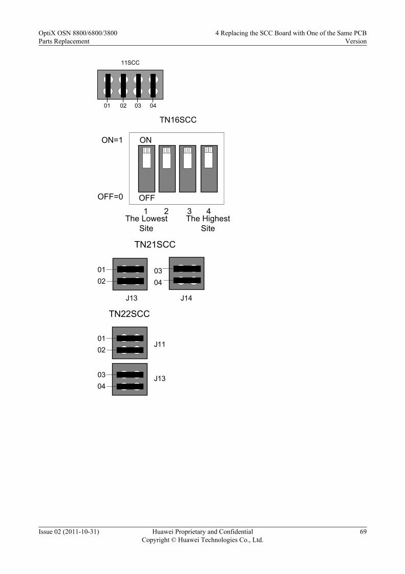
0401 02 03
11SCC
ON
OFF1 2 43
The Lowest Site
ON=1
OFF=0
TN16SCC
The Highest Site
0102
J13 J14
0304
TN21SCC
0102
J11
J130304
TN22SCC
OptiX OSN 8800/6800/3800Parts Replacement
4 Replacing the SCC Board with One of the Same PCBVersion
Issue 02 (2011-10-31) Huawei Proprietary and ConfidentialCopyright © Huawei Technologies Co., Ltd.
69
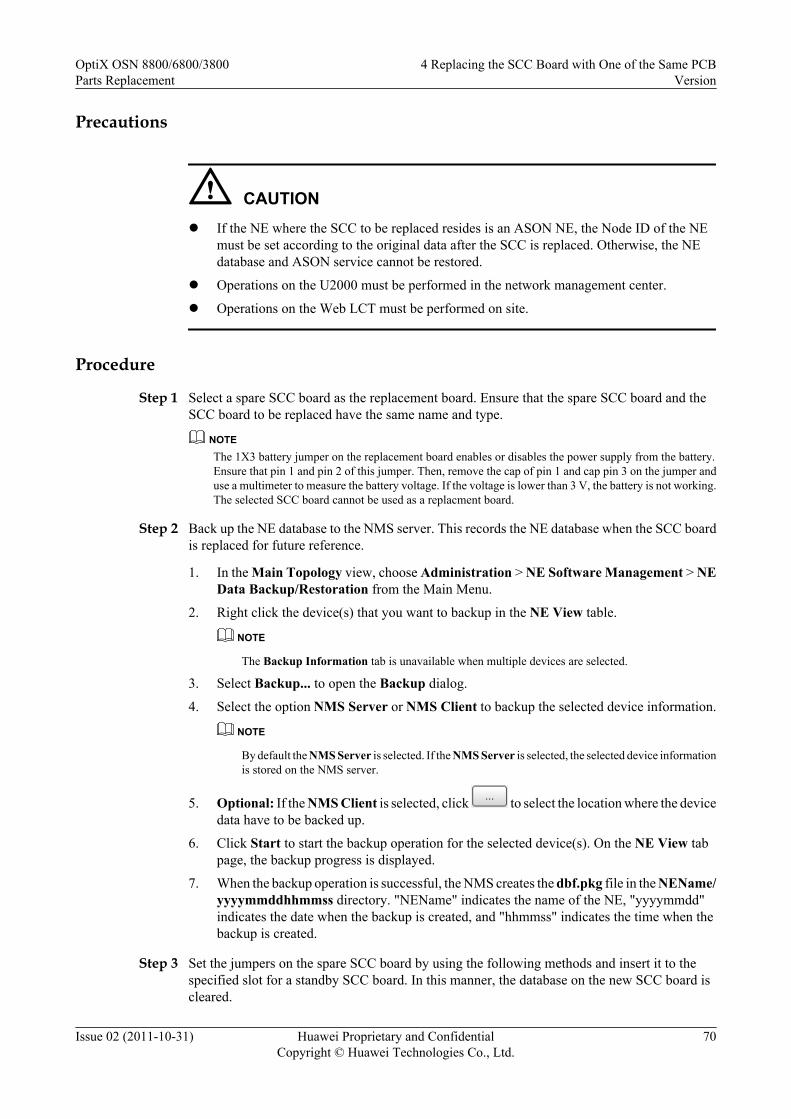
Precautions
CAUTIONl If the NE where the SCC to be replaced resides is an ASON NE, the Node ID of the NE
must be set according to the original data after the SCC is replaced. Otherwise, the NEdatabase and ASON service cannot be restored.
l Operations on the U2000 must be performed in the network management center.
l Operations on the Web LCT must be performed on site.
Procedure
Step 1 Select a spare SCC board as the replacement board. Ensure that the spare SCC board and theSCC board to be replaced have the same name and type.
NOTEThe 1X3 battery jumper on the replacement board enables or disables the power supply from the battery.Ensure that pin 1 and pin 2 of this jumper. Then, remove the cap of pin 1 and cap pin 3 on the jumper anduse a multimeter to measure the battery voltage. If the voltage is lower than 3 V, the battery is not working.The selected SCC board cannot be used as a replacment board.
Step 2 Back up the NE database to the NMS server. This records the NE database when the SCC boardis replaced for future reference.
1. In the Main Topology view, choose Administration > NE Software Management > NEData Backup/Restoration from the Main Menu.
2. Right click the device(s) that you want to backup in the NE View table.
NOTE
The Backup Information tab is unavailable when multiple devices are selected.
3. Select Backup... to open the Backup dialog.
4. Select the option NMS Server or NMS Client to backup the selected device information.
NOTE
By default the NMS Server is selected. If the NMS Server is selected, the selected device informationis stored on the NMS server.
5. Optional: If the NMS Client is selected, click to select the location where the devicedata have to be backed up.
6. Click Start to start the backup operation for the selected device(s). On the NE View tabpage, the backup progress is displayed.
7. When the backup operation is successful, the NMS creates the dbf.pkg file in the NEName/yyyymmddhhmmss directory. "NEName" indicates the name of the NE, "yyyymmdd"indicates the date when the backup is created, and "hhmmss" indicates the time when thebackup is created.
Step 3 Set the jumpers on the spare SCC board by using the following methods and insert it to thespecified slot for a standby SCC board. In this manner, the database on the new SCC board iscleared.
OptiX OSN 8800/6800/3800Parts Replacement
4 Replacing the SCC Board with One of the Same PCBVersion
Issue 02 (2011-10-31) Huawei Proprietary and ConfidentialCopyright © Huawei Technologies Co., Ltd.
70

NOTE
After inserting the spare SCC board to the specified slot for a standby SCC board, you need to add a correspondinglogical board on the U2000. Then, the system automatically configures 1+1 protection for the SCC.
1. Set the BIOS running mode of the spare SCC board to 1111 so as to clear the database inthe flash memory. Figure 4-36 shows the settings of the four jumpers on the SCC board.
2. Insert the spare SCC board to the slot housing the original SCC board.
NOTE
After the four jumpers are set and the SCC board is inserted to the slot, you must wait approximately 15minutes to allow the database to clear.
Step 4 After the database of the SCC board is cleared completely, remove the board. Remove the jumpercaps which are shown in Step 3. After that, reinsert this SCC board to the slot.
Step 5 Review the indicators of the new board. It takes 90 minutes for a board to work normally afterthe board is inserted. Ensure that the STAT indicator is steady green. If the indicator givesabnormal indication, you need to reinsert the board, or replace the board again. For details aboutindicator definitions, see "Indicators" of the Hardware Description.
Step 6 Wait for 90 minutes. After the SCC board starts, add the logical board of the SCC board on theU2000.
Step 7 Log in to the U2000 and complete the following steps to perform an active/standby switchbetween the SCC boards.
1. In the Main Topology, right-click the desire NE and click NE Explorer from the shortcutmenu. The NE Explorer window is displayed.
2. Choose Configuration > Board 1+1 Protection from the Function Tree.3. In Board 1+1 Protection, right-click the desired SCC Board 1+1 Protection. Select
Working/Protection Switching from the shortcut menu. Click OK in the windowdisplayed.
4. Click Query. If the Active Board is not the board to be replaced, the switching is successful.5. Query the alarms and performance events on the U2000. Check if services are normal. If
services are normal, there must be no new abnormal alarms or performances. The switchingis successful.
NOTEAfter the new SCC board is started, the system automatically backs up the data on the existing SCC boardto the new SCC board. After the data is backed up, you can perform the preceding step to initiate an active/standby switching.
Step 8 Check and set the other parameters on the U2000 to ensure that the parameter values of the newboard are the same as the original data.1. Check the software information of the new SCC against the original data.2. Synchronize the NE time with the NMS server time.3. Check the NE alarm attribute data against the original data. The data include saving mode,
reversion mode and delayed report.4. Check the alarm suppression setting data against the original data.5. Enable the NE performance monitoring.
NOTEFor details to set these parameters, see iManager U2000 Operator Guide for NG WDM NE Management.
Step 9 Querying the current alarms of the NE by using the U2000.
OptiX OSN 8800/6800/3800Parts Replacement
4 Replacing the SCC Board with One of the Same PCBVersion
Issue 02 (2011-10-31) Huawei Proprietary and ConfidentialCopyright © Huawei Technologies Co., Ltd.
71
1. In the Main Topology view, choose Fault > Browse Current Alarm from the Main Menu.2. Click the Basic Setting and Alarm Source tabs in turn on the Filter dialog box to set the
filter conditions for the current alarms.3. Click OK.4. Record the current alarms of the NE.
NOTEYou can select the desired alarms and right-click to choose Save > Save Selected Records, or right-click to choose Save > Save All Records from the shortcut menu to save the current alarms of theNE.
NOTEAfter replacing the SCC is replaced, ensure that the monitoring of the POWER_FAIL alarm is enabled. Ifthe POWER_FAIL alarm occurs, and the alarm parameter is 0x5 0xff 0xff 0xff 0xff, the battery of the SCCboard is abnormal, check whether the jumper cap is correctly placed over the battery jumper. If yes, use amultimeter to measure the battery voltage. If the voltage is lower than 3 V, the battery is out of work. Theboard must be replaced.
CAUTIONThe standard voltage of the battery is 3.6 V. The battery is fixed on the board and cannot bereplaced.
Step 10 Remove the SCC board to be replaced and put it in an ESD bag. Then, on the U2000, delete thelogical board of the SCC board to be replaced.
----End
4.3.4 Replacing the SCC Board with the Database Backed Up to theNMS (NE Is Reachable)
Before replacing an SCC board, you can back up the NE database to the NMS if the NE isreachable and the slot for housing the standby SCC board is occupied by a service board. In thismanner, you can restore the NE database from the NMS after replacing the SCC board.
Prerequisitel You must be an NM user with "NE and network operator" authority or higher.l The FTP/TFTP/SFTP server is configured and the FTP/TFTP/SFTP service is started. For
more information, see U2000 NE Software Management.l The SCC replacement board must be the same type as the SCC board being replaced.
Impact on System
Replacing the SCC board does not affect traditional services, but ASON services may be affectedfor a short time when configurations are restored by downloading the database.
Tools, Equipment, and Materials
ESD bag, U2000, multimeter, Web LCT
OptiX OSN 8800/6800/3800Parts Replacement
4 Replacing the SCC Board with One of the Same PCBVersion
Issue 02 (2011-10-31) Huawei Proprietary and ConfidentialCopyright © Huawei Technologies Co., Ltd.
72

Background InformationBefore replacing an SCC board with a spare SCC board, set the battery jumper on the spare SCCboard with reference to 4.1 Setting the Battery Jumper on the SCC.
You must clear the database on the spare SCC board before replacing the replacement board.You can clear the database by setting the BIOS running mode by using four jumpers on thereplacement SCC board. The figure below shows the four jumpers for setting the BIOS runningmode and the battery jumper on an SCC board. The four jumpers for setting the BIOS runningmode are arranged from high order to low order and identified as 04, 03, 02, and 01.
The setting of each of the four jumpers corresponds to a binary value, either 0 or 1. When ajumper is not capped, the setting corresponds to binary 0. When a jumper is capped, the settingcorresponds to binary 1. The settings of the four jumpers can be arranged in 16 combinations,representing 0 to 15 in the decimal system. The default setting of the four jumpers is 0000.
OptiX OSN 8800/6800/3800Parts Replacement
4 Replacing the SCC Board with One of the Same PCBVersion
Issue 02 (2011-10-31) Huawei Proprietary and ConfidentialCopyright © Huawei Technologies Co., Ltd.
73

Figure 4-37 Position of the BIOS running mode jumper on the TN11SCC
CPU
Battery jumper
CFCard
1
2
3
Battery jumper
01020304
BIOS Running Mode
OptiX OSN 8800/6800/3800Parts Replacement
4 Replacing the SCC Board with One of the Same PCBVersion
Issue 02 (2011-10-31) Huawei Proprietary and ConfidentialCopyright © Huawei Technologies Co., Ltd.
74

Figure 4-38 Position of the BIOS running mode jumper on the TN16SCC
CF Card
Battery Jumper
3 2 1
J1SW1
OFF
ON
431 2
BIOS Running
Mode
OptiX OSN 8800/6800/3800Parts Replacement
4 Replacing the SCC Board with One of the Same PCBVersion
Issue 02 (2011-10-31) Huawei Proprietary and ConfidentialCopyright © Huawei Technologies Co., Ltd.
75

Figure 4-39 Position of the BIOS running mode jumper on the TN21/TN22SCC
CPU
Battery jumper
1
2
3
Battery jumper
J13J14
BIOS Running Mode
TN21SCC
CPU
Battery jumper
1
2
3
Battery jumper
J11J13
BIOS Running Mode
TN22SCC
OptiX OSN 8800/6800/3800Parts Replacement
4 Replacing the SCC Board with One of the Same PCBVersion
Issue 02 (2011-10-31) Huawei Proprietary and ConfidentialCopyright © Huawei Technologies Co., Ltd.
76

Figure 4-40 Position of the BIOS running mode jumper on the TNK2SCC
J44
Battery Jumper
CPU
3 21B
attery Supply CF
J9
01020304
BIOS Running Mode
Figure 4-41 Position of the BIOS running mode jumper on the TN51SCC
Battery Supply
U42J12
J42
3 2 1CPU
J1
U45
CF Card
Battery Jumper
BIOS Running Mode
01020304
OptiX OSN 8800/6800/3800Parts Replacement
4 Replacing the SCC Board with One of the Same PCBVersion
Issue 02 (2011-10-31) Huawei Proprietary and ConfidentialCopyright © Huawei Technologies Co., Ltd.
77

Figure 4-42 Position of the BIOS running mode jumper on the TN52SCC
Battery Supply
U33 U18
CF Card
Jumper 3 2
1C
PU
J1
Battery
J11
01020304
BIOS Running Mode
Figure 4-43 Setting the BIOS running mode to 1011
01
02
03
04
52SCC
02
03
04
51SCC
01
01 02 03 04
K2SCC
0401 02 03
11SCC
OptiX OSN 8800/6800/3800Parts Replacement
4 Replacing the SCC Board with One of the Same PCBVersion
Issue 02 (2011-10-31) Huawei Proprietary and ConfidentialCopyright © Huawei Technologies Co., Ltd.
78

ON
OFF
1 2 43
The Lowest Site
The Highest Site
ON=1
OFF=0
16SCC
0102
J13 J14
0304
TN21SCC
0102
J11
J130304
TN22SCC
Figure 4-44 Setting the BIOS running mode to 1010
01
02
03
04
52SCC
01
02
03
04
51SCC
01 02 03 04
K2SCC
OptiX OSN 8800/6800/3800Parts Replacement
4 Replacing the SCC Board with One of the Same PCBVersion
Issue 02 (2011-10-31) Huawei Proprietary and ConfidentialCopyright © Huawei Technologies Co., Ltd.
79

0401 02 03
11SCC
ON
OFF
1 2 43
The Lowest Site
The Highest Site
ON=1
OFF=0
16SCC
0102
J13 J14
0304
TN21SCC
0102
J11
J130304
TN22SCC
Precautions
CAUTIONl If the NE where the SCC to be replaced resides is an ASON NE, the Node ID of the NE
must be set according to the original data after the SCC is replaced. Otherwise, the NEdatabase and ASON service cannot be restored.
l Operations on the U2000 must be performed in the network management center.
l Operations on the Web LCT must be performed on site.
Procedure
Step 1 Select a spare SCC board as the replacement board. Ensure that the spare SCC board and theSCC board to be replaced have the same name and are of the same type.
OptiX OSN 8800/6800/3800Parts Replacement
4 Replacing the SCC Board with One of the Same PCBVersion
Issue 02 (2011-10-31) Huawei Proprietary and ConfidentialCopyright © Huawei Technologies Co., Ltd.
80

NOTEThe 1X3 battery jumper on the replacement board enables or disables the power supply from the battery.Ensure that pin 1 and pin 2 of this jumper. Then, remove the cap of pin 1 and cap pin 3 on the jumper anduse a multimeter to measure the battery voltage. If the voltage is lower than 3 V, the battery is not working.The selected SCC board cannot be used as a replacment board.
Step 2 Review and record the current alarms on the NE. For more information, refer to "Querying theCurrent Alarms" of the Supporting Tasks.
Step 3 Back up the NE database to the NMS server. This records the NE database when the SCC boardis faulty for future reference.
1. In the Main Topology view, choose Administration > NE Software Management > NEData Backup/Restoration from the Main Menu.
2. Right click the device(s) that you want to backup in the NE View table.
NOTE
The Backup Information tab is unavailable when multiple devices are selected.
3. Select Backup... to open the Backup dialog.4. Select the option NMS Server or NMS Client to backup the selected device information.
NOTE
By default the NMS Server is selected. If the NMS Server is selected, the selected device informationis stored on the NMS server.
5. Optional: If the NMS Client is selected, click to select the location where the devicedata have to be backed up.
6. Click Start to start the backup operation for the selected device(s). On the NE View tabpage, the backup progress is displayed.
7. When the backup operation is successful, the NMS creates the dbf.pkg file in the NEName/yyyymmddhhmmss directory. "NEName" indicates the name of the NE, "yyyymmdd"indicates the date when the backup is created, and "hhmmss" indicates the time when thebackup is created.
Step 4 Follow the steps below to query the system to obtain the user data of the NE.
1. In the NE Explorer, select an NE and choose Security > NE User Management from theFunction Tree.
2. Click Query.3. Record the NE user data returned by the system for future restoration of the NE user data.
Step 5 Follow the steps below to query the NE communication parameters.
1. Select the NE you just created, and click the NE Explorer.2. Select Communication > Communication Parameters from Function Tree.3. Record NE communication parameters such as the IP address and the subnet mask in case
you need them for parameter restoration.
Step 6 If the NE is an ASON NE, query and record the node ID of the NE.
1. In the NE Explorer, select an NE and choose ASON > ASON Feature Management fromthe Function Tree.
2. Click the Node ID Management tab.3. Click Query, and record the node ID.
OptiX OSN 8800/6800/3800Parts Replacement
4 Replacing the SCC Board with One of the Same PCBVersion
Issue 02 (2011-10-31) Huawei Proprietary and ConfidentialCopyright © Huawei Technologies Co., Ltd.
81
Step 7 Inform the onsite maintenance engineer and remove the board. For details about how to removea board, see "Replacing a Board" of the Supporting Tasks.
Step 8 Set the jumpers on the spare SCC board by using the following methods and insert it to the slothousing the original SCC board. In this manner, the database on the new SCC board is cleared.1. Set the BIOS running mode of the spare SCC board to 1011 to clear the database in the
flash memory. Figure 4-43 shows the settings of the four jumpers on the SCC board.2. Insert the spare SCC board to the slot housing the original SCC board.3. Wait for a few minutes until the PROG indicator is green and slowly flashes. Remove the
spare SCC board and then set its BIOS running mode to 1010 to clear the system parameterarea. For the settings of the four jumpers on the SCC board, see Figure 4-44. After that,reinsert the new SCC board to the slot.
NOTE
After the four BIOS jumpers are set and you install the SCC board in the slot, the PROG indicator on theSCC board is constantly green, which indicates that the database is being cleared. Wait for a few minutesuntil the PROG indicator blinks green, which indicates that the database is cleared completely.
Step 9 After the database of the SCC board is cleared completely, remove the board. Remove the jumpercaps which are shown in Step 8. After that, reinsert this SCC board to the slot.
Step 10 After the new SCC board is started, connect the Web LCT to the NE. Modify the NE attributeto restore the communication between the NE and the U2000.1. Disconnect the cables from the NM_ETH1 and NM_ETH2 ports (if connected). That is,
disconnect the NE from the computer where the U2000 (hereinafter the computer is referredto as U2000) is installed.
2. Connect the Web LCT to NM_ETH1.3. Set the IP address of the Web LCT to ensure that Web LCT is in the same IP subnet segment
as the NE IP address. If the IP address of the Web LCT and the NE IP address are in differentnetwork segments, the Web LCT cannot be connected to the NE.
NOTEThe new board is initiated at factory, and the default IP subnet segment of the board is 129.9.*.*.
4. Log in the Web LCT with the user name admin, and the initial password admin.
Step 11 Create the NE by using the Web LCT.
1. Click NE Search > Advanced Search in the NE List. The Search NE dialog box isdisplayed.
2. Click Manage Domain. The Manage Domain Search dialog box is displayed.3. Click Add, and the New Domain dialog box is displayed.4. Set Domain Type to GNE IP Domain or GNE IP Address, and enter an IP address in the
Domain Address field.5. Click OK.
NOTEYou can repeat step 3 through 5 to add multiple search domains.
6. Click Cancel to exit the Manage Domain Search dialog box.7. Select appropriate network segment IP addresses within the Domain and click Search.
NOTE
l The NE search function searches out only the NEs in the specified network segment.
l When the search is in progress, you can click End Search.
OptiX OSN 8800/6800/3800Parts Replacement
4 Replacing the SCC Board with One of the Same PCBVersion
Issue 02 (2011-10-31) Huawei Proprietary and ConfidentialCopyright © Huawei Technologies Co., Ltd.
82
8. After the search is complete, select an NE from the list and click Add NE. A promptmessage is displayed, indicating that the NE is successfully added. Click OK.
9. Select the NE that you want to log in and click NE Login in the lower right corner or right-click the NE and choose NE Login. In the NE Login dialog box that is displayed, enterlct and password in the User Name and Password fields, and then click OK.
TIP
You can select multiple NEs at a time by concurrently pressing Shift.
If you select the Use same user name and password to login check box, you can log in to multipleNEs at a time by entering the user name and password only in the first line.
If you select the Use the user name and password that was used last time check box, you do notneed to enter the use name and password and the system automatically uses the user name andpassword for login last time.
Step 12 Modify the NE IP based on the original information by using the Web LCT.
1. In the NE Explorer, select Communication > Communication Parameters fromFunction Tree.
2. Enter the IP Address, and click Apply.3. Click OK after the warning dialog box pops up.4. Click OK after the warning dialog box about communication interruption between NEs
pops up.5. Click Close after the Result dialog box is displayed.
NOTEIf the NE IP addresses before and after the modification are in different network segments, the Web LCT cannotbe connected to the NE. When this occurs, set the IP address of the Web LCT in the same network segment asthe NE IP address.
Step 13 Modify the gateway IP based on the original information by using the Web LCT.
1. In the NE Explorer, Select Communication > Communication Parameters fromFunction Tree.
2. Enter the Gateway IP Address, and click Apply.3. Click OK after the Warning dialogue box pops up that prompts "The NE communication
parameters have been changed. Are you sure to send it? ".4. Click OK after the Warning dialogue box pops up that prompts "Incorrect operations will
interrupt the communication between NEs. Are you sure to continue? ".
Step 14 Modify the subnet mask based on the original information by using the Web LCT.
1. In the NE Explorer, Select Communication > Communication Parameters fromFunction Tree.
2. Enter the Subnet Mask, and click Apply.3. Click OK after the Warning dialogue box pops up that prompts "The NE communication
parameters have been changed. Are you sure to send it? ".4. Click OK after the Warning dialogue box pops up that prompts "Incorrect operations will
interrupt the communication between NEs. Are you sure to continue? ".
Step 15 Modify the NE ID and extended ID based on the original information by using the Web LCT.
1. In the NE Explorer, choose Configuration > NE Attribute from the Function Tree.2. Click Modify NE ID. In the Modify NE ID dialog box that is displayed, enter values in
the New ID and New Extended ID fields, and then click OK.
OptiX OSN 8800/6800/3800Parts Replacement
4 Replacing the SCC Board with One of the Same PCBVersion
Issue 02 (2011-10-31) Huawei Proprietary and ConfidentialCopyright © Huawei Technologies Co., Ltd.
83

3. A warning dialog box is displayed, click Yes. A dialog box indicating that the operation issuccessful is displayed, click Close to complete changing the NE ID. At this time, the NEis unreachable.
Step 16 Check the NE communication parameters by using the Web LCT.
1. Select the NE you just created, and click the NE Explorer.
2. Select Communication > Communication Parameters from Function Tree.
3. Check that all NE communication parameters should be the same with the original ones.
Step 17 Create an NE's user by using the Web LCT.
1. In the NE Explorer, select the NE and choose Security > NE User Management from theFunction Tree.
2. Click Create and the Add NE User dialog box is displayed.
3. Enter the NE user name in the NE User field.
4. Select the User Level as needed.
5. Enter the password in the New Password field and enter it again in the ConfirmPassword field.
NOTE
You also need to set the Whether the password is allowed to be modified immediately parameter.
The password is a string of 6-16 characters. It can consist of letters, symbols and numerals, and mustcontain at least one letter and one numeral.
6. Click OK.
7. Click Query, and the Operation Result dialog box is displayed. Click Close. All createdusers of the NE are displayed in NE User Management Table.
Step 18 If the NE is an ASON NE, modify the node ID of the NE by using the Web LCT.
1. In the NE Explorer, select an NE and choose ASON > ASON Feature Management fromthe Function Tree. Click the Node ID Management tab.
2. Click Query to view the current node ID of the NE.
3. Double-click the Node ID field to enter a node ID for the NE.
4. Click Apply. After you confirm the operation twice, a prompt appears telling you that theoperation was successful.
NOTE
You can also choose Configuration > WDM ASON > ASON Topology Management from the mainmenu and set the NE node ID.
Step 19 Recover the network connection of the NE.
1. Remove the network cable which connected the NM_ETH1 port to the Web LCT.
2. Connect the network cable removed in the Step 10.
NOTEAfter this procedure, you can use the original user name and password to access the NE by using theU2000.
Step 20 If the software version of the spare SCC board is different from the software version of the SCCboard to be replaced, go to Step 21, otherwise go to Step 22.
OptiX OSN 8800/6800/3800Parts Replacement
4 Replacing the SCC Board with One of the Same PCBVersion
Issue 02 (2011-10-31) Huawei Proprietary and ConfidentialCopyright © Huawei Technologies Co., Ltd.
84
Step 21 Upgrade or downgrade the software of the spare SCC board. For details, see the UpgradeGuide. Ensure that the software version of the spare SCC board is consistent with that of theSCC board to be replaced.
Step 22 Restore the NE database from the NMS server.
NOTE
You must activate the NE database within five minutes after restoring it.
1. In the Main Topology view, choose Administration > NE Software Management > NEData Backup/Restoration from the Main Menu.
2. Right click the device(s) that you want to recover in the NE View table.3. Select Recover... to open the Recover dialog.4. In the File Name drop-down list, select the file to be recovered. If the backup file is not
listed in the File Name drop-down list, select the file to be recovered, and turn to 22.6. Ifthe backup file is not listed in the File Name drop-down list, click Browse... to select thebackup file in the Select File dialog box, as shown below.
5. Select NMS Server or NMS Client to recover the backup file for the selected device(s).By default NMS Server is selected.l If NMS Server is selected, you need to select the appropriate backup file from the NMS
server. The selected backup file path is displayed in the File To Be Recovered field.
l If NMS Client is selected, you need to click to select the backup file from theNMS Client. The selected backup file path is displayed in the File To Be Recoveredfield.
6. Click OK.
NOTE
The selected backup file path from the NMS Server or NMS Client is displayed in the File Name drop-down list.
7. Click Start, the Operation Confirmation dialog box is displayed.8. In the Operation Confirmation dialog, click Yes to start the recover operation. The
recover operation status is displayed in the NE View table.
CAUTIONDuring the process from backing up databases to restoring databases, do not modify the NEconfigurations to avoid database inconsistency.
Step 23 Activate the NE database.
1. In the Main Topology view, choose Administration > NE Software Management > NEData Backup/Restoration from the Main Menu.
2. Select the NE where the SCC that has been replaced resides in the NE View table.3. Right-click the NE, a pop-up menu is displayed.4. Select Activate Database..., and the Activate Database dialog box is displayed.
5. Optional: Click the icon in Deliver To Board Activate, and then this icon is changedto . Click Start to start the database activation process. The progress of the databaseactivation is displayed on the NE View tab.
OptiX OSN 8800/6800/3800Parts Replacement
4 Replacing the SCC Board with One of the Same PCBVersion
Issue 02 (2011-10-31) Huawei Proprietary and ConfidentialCopyright © Huawei Technologies Co., Ltd.
85

NOTE
The operation on the U2000 may bring a service interruption.
Step 24 Check and set the other parameters on the U2000 to ensure that the parameter values of the newboard are the same as the original data.1. Check the software information of the new SCC against the original data.2. Synchronize the NE time with the NMS server time.3. Check the NE alarm attribute data against the original data. The data include saving mode,
reversion mode and delayed report.4. Check the alarm suppression setting data against the original data.5. Enable the NE performance monitoring.6. Configure the OSPF IP address of the NE if the site complies with the models for separated
optical and electrical NEs and the NE is on an optical-layer ASON network.
NOTEFor details to set these parameters, see iManager U2000 Operator Guide for NG WDM NE Management.
Step 25 Querying the current alarms of the NE by using the U2000.
1. In the Main Topology view, choose Fault > Browse Current Alarm from the Main Menu.2. Click the Basic Setting and Alarm Source tabs in turn on the Filter dialog box to set the
filter conditions for the current alarms.3. Click OK.4. Record the current alarms of the NE.
NOTEYou can select the desired alarms and right-click to choose Save > Save Selected Records, or right-click to choose Save > Save All Records from the shortcut menu to save the current alarms of theNE.
NOTEAfter replacing the SCC is replaced, ensure that the monitoring of the POWER_FAIL alarm is enabled. Ifthe POWER_FAIL alarm occurs, and the alarm parameter is 0x5 0xff 0xff 0xff 0xff, the battery of the SCCboard is abnormal, check whether the jumper cap is correctly placed over the battery jumper. If yes, use amultimeter to measure the battery voltage. If the voltage is lower than 3 V, the battery is out of work. Theboard must be replaced.
CAUTIONThe standard voltage of the battery is 3.6 V. The battery is fixed on the board and cannot bereplaced.
----End
4.3.5 Replacing the SCC Board with the Database Backed Up to aCF Card (NE Is Reachable)
Before replacing an SCC board, back up the NE database to a CF card if the NE is reachableand the standby SCC slot is occupied by a service board. If you choose to back up the database,you can restore the NE database from the CF card after you replace the SCC board is replaced.
OptiX OSN 8800/6800/3800Parts Replacement
4 Replacing the SCC Board with One of the Same PCBVersion
Issue 02 (2011-10-31) Huawei Proprietary and ConfidentialCopyright © Huawei Technologies Co., Ltd.
86

PrerequisiteYou must be an NM user with "NE and network operator" authority or higher.
The SCC replacement board must be the same type as the SCC board being replaced.
Impact on SystemReplacing the SCC board does not affect traditional services, but ASON services may be affectedfor a short time when configurations are restored by downloading the database.
Tools, Equipment, and MaterialsESD bag, U2000, multimeter, Web LCT
Background InformationBefore an SCC board is replaced with a spare board, the battery jumper on the spare SCC boardmust be set with reference to 4.1 Setting the Battery Jumper on the SCC.
You must clear the database on the spare SCC board before replacing the replacement board.You can clear the database by setting the BIOS running mode by using four jumpers on thereplacement SCC board. The figure below shows the four jumpers for setting the BIOS runningmode together with the battery jumper on an SCC board. The four jumpers for setting the BIOSrunning mode are arranged from high order to low order and identified as 04, 03, 02, and 01.
The setting of each of the four jumpers corresponds to a binary value, either 0 or 1. When ajumper is not capped, the setting corresponds to binary 0. When a jumper is capped, the settingcorresponds to binary 1. The settings of the four jumpers can be arranged in 16 combinations,representing 0 to 15 in the decimal system. The default setting of the four jumpers is 0000.
OptiX OSN 8800/6800/3800Parts Replacement
4 Replacing the SCC Board with One of the Same PCBVersion
Issue 02 (2011-10-31) Huawei Proprietary and ConfidentialCopyright © Huawei Technologies Co., Ltd.
87

Figure 4-45 Position of the BIOS running mode jumper on the TN11SCC
CPU
Battery jumper
CFCard
1
2
3
Battery jumper
01020304
BIOS Running Mode
OptiX OSN 8800/6800/3800Parts Replacement
4 Replacing the SCC Board with One of the Same PCBVersion
Issue 02 (2011-10-31) Huawei Proprietary and ConfidentialCopyright © Huawei Technologies Co., Ltd.
88

Figure 4-46 Position of the BIOS running mode jumper on the TN16SCC
CF Card
Battery Jumper
3 2 1
J1SW1
OFF
ON
431 2
BIOS Running
Mode
Figure 4-47 Position of the BIOS running mode jumper on the TNK2SCC
J44
Battery Jumper
CPU
3 21B
attery Supply CF
J9
01020304
BIOS Running Mode
OptiX OSN 8800/6800/3800Parts Replacement
4 Replacing the SCC Board with One of the Same PCBVersion
Issue 02 (2011-10-31) Huawei Proprietary and ConfidentialCopyright © Huawei Technologies Co., Ltd.
89

Figure 4-48 Position of the BIOS running mode jumper on the TN51SCC
Battery Supply
U42J12
J42
3 2 1CPU
J1
U45
CF Card
Battery Jumper
BIOS Running Mode
01020304
Figure 4-49 Position of the BIOS running mode jumper on the TN52SCC
Battery Supply
U33 U18
CF Card
Jumper 3 2
1C
PU
J1
Battery
J11
01020304
BIOS Running Mode
OptiX OSN 8800/6800/3800Parts Replacement
4 Replacing the SCC Board with One of the Same PCBVersion
Issue 02 (2011-10-31) Huawei Proprietary and ConfidentialCopyright © Huawei Technologies Co., Ltd.
90

Figure 4-50 Setting the BIOS running mode to 1011
01
02
03
04
52SCC
02
03
04
51SCC
01
01 02 03 04
K2SCC
0401 02 03
11SCC
ON
OFF
1 2 43
The Lowest Site
The Highest Site
ON=1
OFF=0
16SCC
OptiX OSN 8800/6800/3800Parts Replacement
4 Replacing the SCC Board with One of the Same PCBVersion
Issue 02 (2011-10-31) Huawei Proprietary and ConfidentialCopyright © Huawei Technologies Co., Ltd.
91
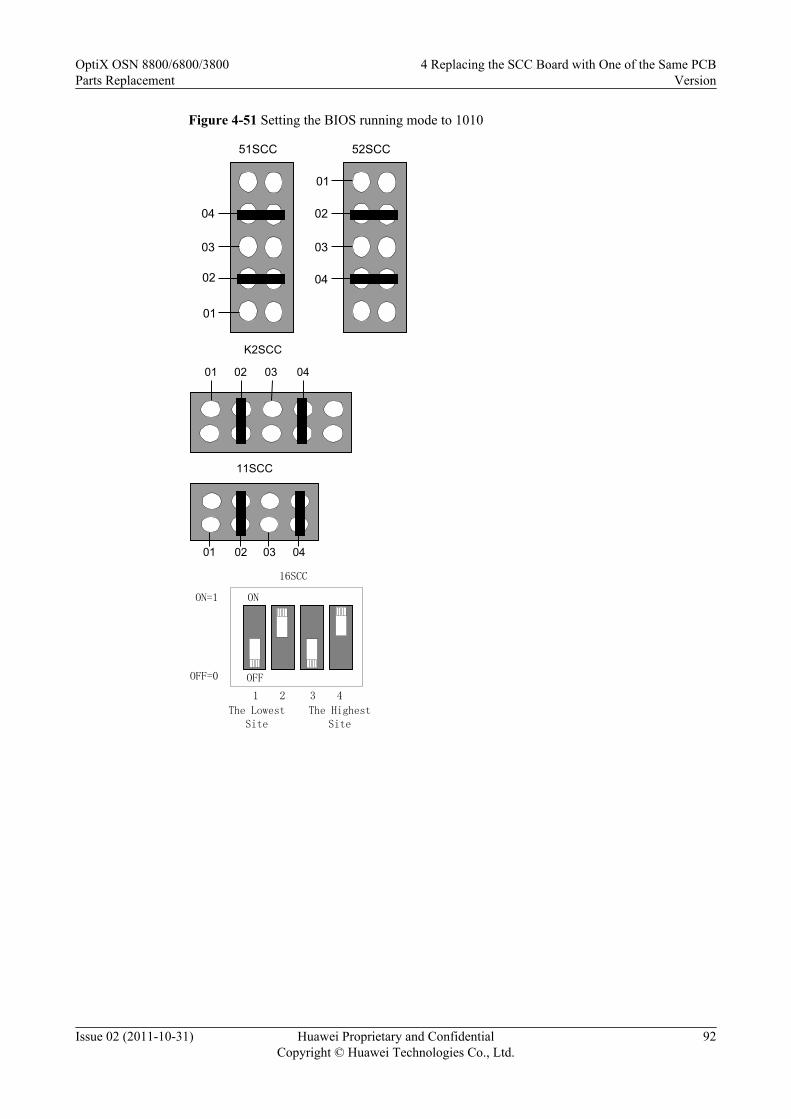
Figure 4-51 Setting the BIOS running mode to 1010
01
02
03
04
52SCC
01
02
03
04
51SCC
01 02 03 04
K2SCC
0401 02 03
11SCC
ON
OFF
1 2 43
The Lowest Site
The Highest Site
ON=1
OFF=0
16SCC
OptiX OSN 8800/6800/3800Parts Replacement
4 Replacing the SCC Board with One of the Same PCBVersion
Issue 02 (2011-10-31) Huawei Proprietary and ConfidentialCopyright © Huawei Technologies Co., Ltd.
92
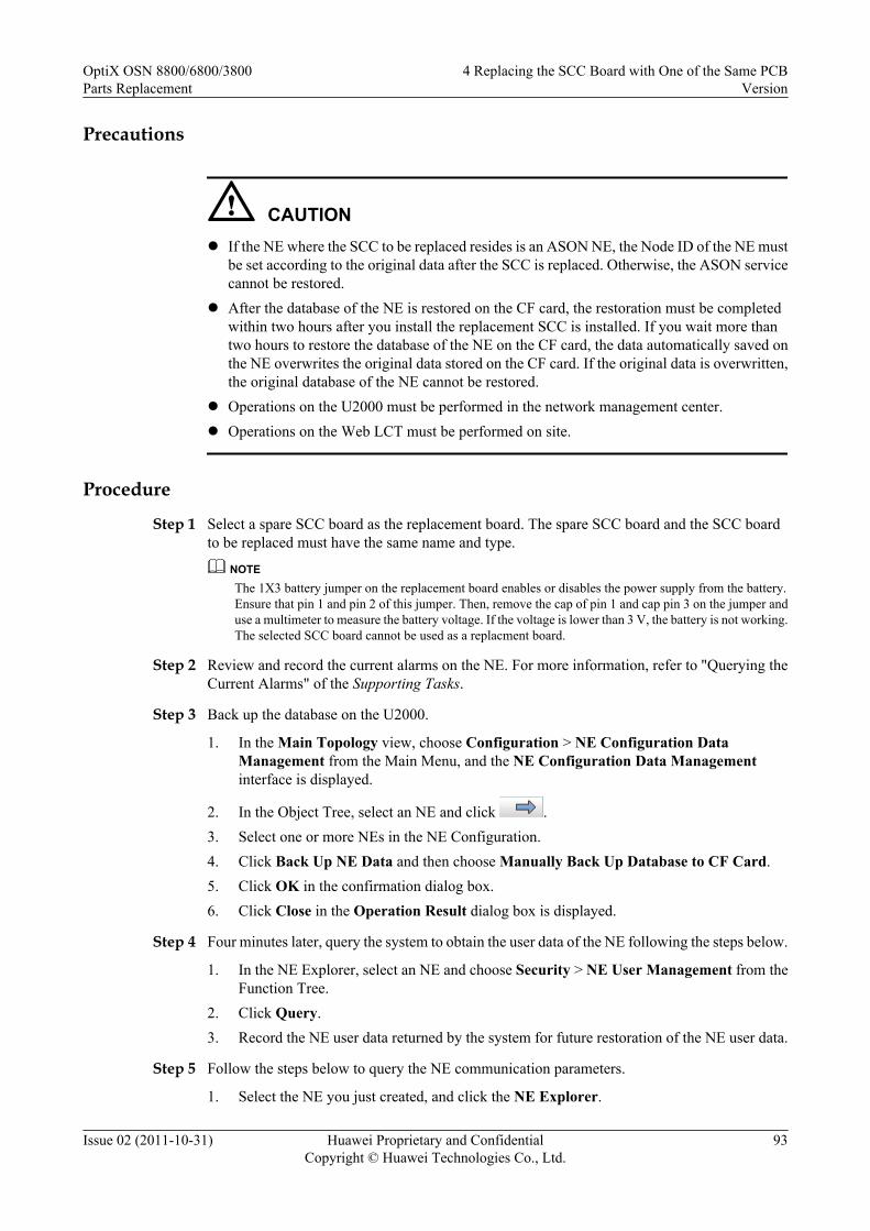
Precautions
CAUTIONl If the NE where the SCC to be replaced resides is an ASON NE, the Node ID of the NE must
be set according to the original data after the SCC is replaced. Otherwise, the ASON servicecannot be restored.
l After the database of the NE is restored on the CF card, the restoration must be completedwithin two hours after you install the replacement SCC is installed. If you wait more thantwo hours to restore the database of the NE on the CF card, the data automatically saved onthe NE overwrites the original data stored on the CF card. If the original data is overwritten,the original database of the NE cannot be restored.
l Operations on the U2000 must be performed in the network management center.l Operations on the Web LCT must be performed on site.
Procedure
Step 1 Select a spare SCC board as the replacement board. The spare SCC board and the SCC boardto be replaced must have the same name and type.
NOTEThe 1X3 battery jumper on the replacement board enables or disables the power supply from the battery.Ensure that pin 1 and pin 2 of this jumper. Then, remove the cap of pin 1 and cap pin 3 on the jumper anduse a multimeter to measure the battery voltage. If the voltage is lower than 3 V, the battery is not working.The selected SCC board cannot be used as a replacment board.
Step 2 Review and record the current alarms on the NE. For more information, refer to "Querying theCurrent Alarms" of the Supporting Tasks.
Step 3 Back up the database on the U2000.
1. In the Main Topology view, choose Configuration > NE Configuration DataManagement from the Main Menu, and the NE Configuration Data Managementinterface is displayed.
2. In the Object Tree, select an NE and click .3. Select one or more NEs in the NE Configuration.4. Click Back Up NE Data and then choose Manually Back Up Database to CF Card.5. Click OK in the confirmation dialog box.6. Click Close in the Operation Result dialog box is displayed.
Step 4 Four minutes later, query the system to obtain the user data of the NE following the steps below.
1. In the NE Explorer, select an NE and choose Security > NE User Management from theFunction Tree.
2. Click Query.3. Record the NE user data returned by the system for future restoration of the NE user data.
Step 5 Follow the steps below to query the NE communication parameters.
1. Select the NE you just created, and click the NE Explorer.
OptiX OSN 8800/6800/3800Parts Replacement
4 Replacing the SCC Board with One of the Same PCBVersion
Issue 02 (2011-10-31) Huawei Proprietary and ConfidentialCopyright © Huawei Technologies Co., Ltd.
93

2. Select Communication > Communication Parameters from Function Tree.3. Record NE communication parameters such as the IP address and the subnet mask in case
you need them for parameter restoration.
Step 6 If the NE is an ASON NE, query and record the node ID of the NE.
1. In the NE Explorer, select an NE and choose ASON > ASON Feature Management fromthe Function Tree.
2. Click the Node ID Management tab.3. Click Query, and record the node ID.
Step 7 Remove the SCC board to be replaced. For more information, see "Replacing a Board" of theSupporting Tasks.
Step 8 On the SCC board that has been removed, hold the CF card and pull the card out of the CF cardslot. Put the SCC into an ESD bag.
NOTE
Keep the CF card because it is required for NE data restoration.
Step 9 Set the four jumpers on the spare SCC board so as to set the BIOS running mode and insert theSCC board to the slot housing the original SCC board. In this manner, the database on the newSCC board is cleared.1. Set the BIOS running mode of the spare SCC board to 1011 to clear the database in the
flash memory. Figure 4-50 shows the settings of the four jumpers on the SCC board.2. Insert the spare SCC board to the slot housing the original SCC board.3. Wait for a few minutes until the PROG indicator is green and slowly flashes. Remove the
spare SCC board and then set its BIOS running mode to 1010 to clear the system parameterarea. For settings of the four jumpers on the SCC board, see Figure 4-51. After that, reinsertthe new SCC board to the slot.
NOTE
After the four BIOS jumpers are set and you install the SCC board in the slot, the PROG indicator on theSCC board is constantly green, which indicates that the database is being cleared. Wait for a few minutesuntil the PROG indicator blinks green, which indicates that the database is cleared completely.
Step 10 After the database of the SCC board is cleared completely, remove the board. Remove the jumpercaps which are shown in Step 9. After that, reinsert this SCC board to the slot.
Step 11 After the new SCC board is started, connect the Web LCT to the NE. Modify the NE attributeto restore the communication between the NE and the U2000.1. Disconnect the cables from the NM_ETH1 and NM_ETH2 ports (if connected). That is,
disconnect the NE from the computer where the U2000 (hereinafter the computer is referredto as U2000) is installed.
2. Connect the Web LCT to NM_ETH1.3. Set the IP address of the Web LCT to ensure that Web LCT is in the same IP subnet segment
as the NE IP address. If the IP address of the Web LCT and the NE IP address are in differentnetwork segments, the Web LCT cannot be connected to the NE.
NOTEThe new board is initiated at factory, and the default IP subnet segment of the board is 129.9.*.*.
4. Log in the Web LCT with the user name admin, and the initial password admin.
Step 12 Create the NE by using the Web LCT.
OptiX OSN 8800/6800/3800Parts Replacement
4 Replacing the SCC Board with One of the Same PCBVersion
Issue 02 (2011-10-31) Huawei Proprietary and ConfidentialCopyright © Huawei Technologies Co., Ltd.
94

1. Click NE Search > Advanced Search in the NE List. The Search NE dialog box isdisplayed.
2. Click Manage Domain. The Manage Domain Search dialog box is displayed.3. Click Add, and the New Domain dialog box is displayed.4. Set Domain Type to GNE IP Domain or GNE IP Address, and enter an IP address in the
Domain Address field.5. Click OK.
NOTEYou can repeat step 3 through 5 to add multiple search domains.
6. Click Cancel to exit the Manage Domain Search dialog box.7. Select appropriate network segment IP addresses within the Domain and click Search.
NOTE
l The NE search function searches out only the NEs in the specified network segment.
l When the search is in progress, you can click End Search.
8. After the search is complete, select an NE from the list and click Add NE. A promptmessage is displayed, indicating that the NE is successfully added. Click OK.
9. Select the NE that you want to log in and click NE Login in the lower right corner or right-click the NE and choose NE Login. In the NE Login dialog box that is displayed, enterlct and password in the User Name and Password fields, and then click OK.
TIP
You can select multiple NEs at a time by concurrently pressing Shift.
If you select the Use same user name and password to login check box, you can log in to multipleNEs at a time by entering the user name and password only in the first line.
If you select the Use the user name and password that was used last time check box, you do notneed to enter the use name and password and the system automatically uses the user name andpassword for login last time.
Step 13 Modify the NE IP based on the original information by using the Web LCT.
1. In the NE Explorer, select Communication > Communication Parameters fromFunction Tree.
2. Enter the IP Address, and click Apply.3. Click OK after the warning dialog box pops up.4. Click OK after the warning dialog box about communication interruption between NEs
pops up.5. Click Close after the Result dialog box is displayed.
NOTEIf the NE IP addresses before and after the modification are in different network segments, the Web LCT cannotbe connected to the NE. When this occurs, set the IP address of the Web LCT in the same network segment asthe NE IP address.
Step 14 Modify the gateway IP based on the original information by using the Web LCT.
1. In the NE Explorer, Select Communication > Communication Parameters fromFunction Tree.
2. Enter the Gateway IP Address, and click Apply.3. Click OK after the Warning dialogue box pops up that prompts "The NE communication
parameters have been changed. Are you sure to send it? ".
OptiX OSN 8800/6800/3800Parts Replacement
4 Replacing the SCC Board with One of the Same PCBVersion
Issue 02 (2011-10-31) Huawei Proprietary and ConfidentialCopyright © Huawei Technologies Co., Ltd.
95

4. Click OK after the Warning dialogue box pops up that prompts "Incorrect operations willinterrupt the communication between NEs. Are you sure to continue? ".
Step 15 Modify the subnet mask based on the original information by using the Web LCT.
1. In the NE Explorer, Select Communication > Communication Parameters fromFunction Tree.
2. Enter the Subnet Mask, and click Apply.3. Click OK after the Warning dialogue box pops up that prompts "The NE communication
parameters have been changed. Are you sure to send it? ".4. Click OK after the Warning dialogue box pops up that prompts "Incorrect operations will
interrupt the communication between NEs. Are you sure to continue? ".
Step 16 Modify the NE ID and extended ID based on the original information by using the Web LCT.
1. In the NE Explorer, choose Configuration > NE Attribute from the Function Tree.2. Click Modify NE ID. In the Modify NE ID dialog box that is displayed, enter values in
the New ID and New Extended ID fields, and then click OK.3. A warning dialog box is displayed, click Yes. A dialog box indicating that the operation is
successful is displayed, click Close to complete changing the NE ID. At this time, the NEis unreachable.
Step 17 Check the NE communication parameters by using the Web LCT.
1. Select the NE you just created, and click the NE Explorer.2. Select Communication > Communication Parameters from Function Tree.3. Check that all NE communication parameters should be the same with the original ones.
Step 18 Create an NE's user by using the Web LCT.
1. In the NE Explorer, select the NE and choose Security > NE User Management from theFunction Tree.
2. Click Create and the Add NE User dialog box is displayed.3. Enter the NE user name in the NE User field.4. Select the User Level as needed.5. Enter the password in the New Password field and enter it again in the Confirm
Password field.
NOTE
You also need to set the Whether the password is allowed to be modified immediately parameter.
The password is a string of 6-16 characters. It can consist of letters, symbols and numerals, and mustcontain at least one letter and one numeral.
6. Click OK.7. Click Query, and the Operation Result dialog box is displayed. Click Close. All created
users of the NE are displayed in NE User Management Table.
Step 19 If the NE is an ASON NE, modify the node ID of the NE by using the Web LCT.
1. In the NE Explorer, select an NE and choose ASON > ASON Feature Management fromthe Function Tree. Click the Node ID Management tab.
2. Click Query to view the current node ID of the NE.3. Double-click the Node ID field to enter a node ID for the NE.
OptiX OSN 8800/6800/3800Parts Replacement
4 Replacing the SCC Board with One of the Same PCBVersion
Issue 02 (2011-10-31) Huawei Proprietary and ConfidentialCopyright © Huawei Technologies Co., Ltd.
96

4. Click Apply. After you confirm the operation twice, a prompt appears telling you that theoperation was successful.
NOTE
You can also choose Configuration > WDM ASON > ASON Topology Management from the mainmenu and set the NE node ID.
Step 20 Recover the network connection of the NE.1. Remove the network cable which connected the NM_ETH1 port to the Web LCT.2. Connect the network cable removed.
NOTEAfter this procedure, you can use the original user name and password to access the NE by using theU2000.
Step 21 After the SCC board is started, remove the SCC board inserted just now. Insert the CF card thathas been removed in Step 8 into the CF card slot on the SCC board. Then, insert the SCC.
Step 22 After the SCC board is started and the communication between the NE and U2000 is normal,go to Step 19.
Step 23 If the software version of the spare SCC board is different from the software version of the SCCboard to be replaced, go to Step 24, otherwise go to Step 25.
Step 24 Upgrade or downgrade the software of the spare SCC board. For details, see the UpgradeGuide. Ensure that the software version of the spare SCC board is consistent with that of theSCC board to be replaced.
Step 25 Restore the initial database of the NE by using the U2000.
1. In the Main Topology view, choose Configuration > NE Configuration DataManagement from the Main Menu, and the NE Configuration Data Managementinterface is displayed.
2. In the Object Tree on the left, select an NE and click .3. In NE Configuration, select an NE or multiple NEs.4. Click Restore NE Database from CF Card. The Confirm dialog box is displayed,
indicating that the restoration of the NE database may lead to service interruption.5. Click OK to start to restore the NE database.6. Click Closeafter an Operation Result dialog box is displayed.
NOTEAfter the NE databases are restored, the NE software issues the data in the CF card to only the SCC boardbut not other boards. To ensure that the configurations in the SCC board and the configurations in otherboards are consistent, you need to perform warm resets on other boards.
CAUTIONDuring the process from backing up databases to restoring databases, do not modify the NEconfigurations to avoid database inconsistency.
Step 26 Check and set the other parameters on the U2000 to ensure that the parameter values of the newboard are the same as the original data.1. Check the software information of the new SCC against the original data.
OptiX OSN 8800/6800/3800Parts Replacement
4 Replacing the SCC Board with One of the Same PCBVersion
Issue 02 (2011-10-31) Huawei Proprietary and ConfidentialCopyright © Huawei Technologies Co., Ltd.
97

2. Synchronize the NE time with the NMS server time.3. Check the NE alarm attribute data against the original data. The data include saving mode,
reversion mode and delayed report.4. Check the alarm suppression setting data against the original data.5. Enable the NE performance monitoring.6. Configure the OSPF IP address of the NE if the site complies with the models for separated
optical and electrical NEs and the NE is on an optical-layer ASON network.
NOTEFor details to set these parameters, see iManager U2000 Operator Guide for NG WDM NE Management.
Step 27 Querying the current alarms of the NE by using the U2000.
1. In the Main Topology view, choose Fault > Browse Current Alarm from the Main Menu.2. Click the Basic Setting and Alarm Source tabs in turn on the Filter dialog box to set the
filter conditions for the current alarms.3. Click OK.4. Record the current alarms of the NE.
NOTEYou can select the desired alarms and right-click to choose Save > Save Selected Records, or right-click to choose Save > Save All Records from the shortcut menu to save the current alarms of theNE.
NOTEAfter replacing the SCC is replaced, ensure that the monitoring of the POWER_FAIL alarm is enabled. Ifthe POWER_FAIL alarm occurs, and the alarm parameter is 0x5 0xff 0xff 0xff 0xff, the battery of the SCCboard is abnormal, check whether the jumper cap is correctly placed over the battery jumper. If yes, use amultimeter to measure the battery voltage. If the voltage is lower than 3 V, the battery is out of work. Theboard must be replaced.
CAUTIONThe standard voltage of the battery is 3.6 V. The battery is fixed on the board and cannot bereplaced.
----End
4.4 Replacing the SCC Board in a Slave SubrackThis section describes how to replace an SCC board in a slave subrack.
PrerequisiteYou must be an NMS user with "NE and network operator" authority or higher.
The SCC replacement board must be the same type as the SCC board being replaced.
Impact on SystemReplacing the SCC does not affect the existing services.
OptiX OSN 8800/6800/3800Parts Replacement
4 Replacing the SCC Board with One of the Same PCBVersion
Issue 02 (2011-10-31) Huawei Proprietary and ConfidentialCopyright © Huawei Technologies Co., Ltd.
98

If the SCC is configured with 1+1 protection, replacing the SCC does not affect the system.
If an SCC is not configured with 1+1 protection, replacing the SCC has the following effects:l The fan is automatically changed to the "High Speed" mode.l The ESC and OSC communication of the subrack where the replacement SCC resides fails.l The POWER_FAIL alarm of the subrack where the replacement SCC resides cannot be
reported.l The subrack whose ID conflicts with the ID of the subrack where the replacement SCC
resides cannot be detected.l Certain optical boards in the slave subrack housing the SCC board to be replaced go offline
and cannot be managed. However, the services on these boards are not affected.
Tools, Equipment, and MaterialsESD bag, U2000, multimeter
Background InformationBefore an SCC board is replaced with a spare board, you must set the battery jumper on the spareSCC board with reference to 4.1 Setting the Battery Jumper on the SCC.
You must clear the database on the spare SCC board before starting the replacement. You clearthe database by configuring the BIOS running mode by using four setting jumpers on the spareSCC board. The figure below shows the four jumpers for setting the BIOS running mode andthe battery jumper on an SCC board. The four jumpers for setting the BIOS running mode arearranged from high order to low order and identified as 04, 03, 02, and 01.
The setting of each jumper corresponds to a binary value, either 0 or 1. When a jumper is notcapped, the setting corresponds to binary 0. When the jumper is capped, the setting correspondsto binary 1. The settings of the four jumpers can be arranged in 16 combinations, representing0 to 15 in the decimal system. The default setting of the four jumpers is 0000.
OptiX OSN 8800/6800/3800Parts Replacement
4 Replacing the SCC Board with One of the Same PCBVersion
Issue 02 (2011-10-31) Huawei Proprietary and ConfidentialCopyright © Huawei Technologies Co., Ltd.
99

Figure 4-52 Position of the BIOS running mode jumper on the TN11SCC
CPU
Battery jumper
CFCard
1
2
3
Battery jumper
01020304
BIOS Running Mode
OptiX OSN 8800/6800/3800Parts Replacement
4 Replacing the SCC Board with One of the Same PCBVersion
Issue 02 (2011-10-31) Huawei Proprietary and ConfidentialCopyright © Huawei Technologies Co., Ltd.
100

Figure 4-53 Position of the BIOS running mode jumper on the TN16SCC
CF Card
Battery Jumper
3 2 1
J1SW1
OFF
ON
431 2
BIOS Running
Mode
OptiX OSN 8800/6800/3800Parts Replacement
4 Replacing the SCC Board with One of the Same PCBVersion
Issue 02 (2011-10-31) Huawei Proprietary and ConfidentialCopyright © Huawei Technologies Co., Ltd.
101

Figure 4-54 Position of the BIOS running mode jumper on the TN21/TN22SCC
CPU
Battery jumper
1
2
3
Battery jumper
J13J14
BIOS Running Mode
TN21SCC
CPU
Battery jumper
1
2
3
Battery jumper
J11J13
BIOS Running Mode
TN22SCC
OptiX OSN 8800/6800/3800Parts Replacement
4 Replacing the SCC Board with One of the Same PCBVersion
Issue 02 (2011-10-31) Huawei Proprietary and ConfidentialCopyright © Huawei Technologies Co., Ltd.
102

Figure 4-55 Position of the BIOS running mode jumper on the TNK2SCC
J44
Battery Jumper
CPU
3 21B
attery Supply CF
J9
01020304
BIOS Running Mode
Figure 4-56 Position of the BIOS running mode jumper on the TN51SCC
Battery Supply
U42J12
J42
3 2 1CPU
J1
U45
CF Card
Battery Jumper
BIOS Running Mode
01020304
OptiX OSN 8800/6800/3800Parts Replacement
4 Replacing the SCC Board with One of the Same PCBVersion
Issue 02 (2011-10-31) Huawei Proprietary and ConfidentialCopyright © Huawei Technologies Co., Ltd.
103
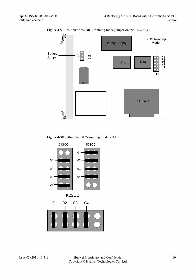
Figure 4-57 Position of the BIOS running mode jumper on the TN52SCC
Battery Supply
U33 U18
CF Card
Jumper 3 2
1C
PU
J1
Battery
J11
01020304
BIOS Running Mode
Figure 4-58 Setting the BIOS running mode to 1111
01
02
03
04
52SCC
01
02
03
04
51SCC
01 02 03 04
K2SCC
OptiX OSN 8800/6800/3800Parts Replacement
4 Replacing the SCC Board with One of the Same PCBVersion
Issue 02 (2011-10-31) Huawei Proprietary and ConfidentialCopyright © Huawei Technologies Co., Ltd.
104

0401 02 03
11SCC
ON
OFF1 2 43
The Lowest Site
ON=1
OFF=0
TN16SCC
The Highest Site
0102
J13 J14
0304
TN21SCC
0102
J11
J130304
TN22SCC
Procedure
Step 1 Select a spare board. Ensure the name, and the type of the spare board are the same as those ofthe original board.
NOTEThe 1X3 jumper inside the board is used to enable or disable the power supply from the battery. Ensurethat pin 1 and pin 2 on the battery jumper are capped. Then, cap pin 2 and pin 3 on the battery jumper anduse a multimeter to measure the battery voltage. If the voltage is lower than 3 V, it indicates that the batteryis not working. In this case, the SCC board needs to be replaced.
OptiX OSN 8800/6800/3800Parts Replacement
4 Replacing the SCC Board with One of the Same PCBVersion
Issue 02 (2011-10-31) Huawei Proprietary and ConfidentialCopyright © Huawei Technologies Co., Ltd.
105
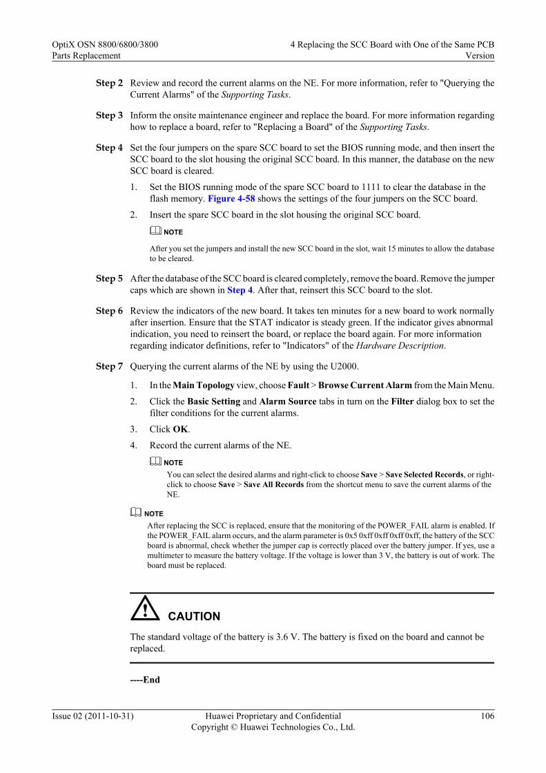
Step 2 Review and record the current alarms on the NE. For more information, refer to "Querying theCurrent Alarms" of the Supporting Tasks.
Step 3 Inform the onsite maintenance engineer and replace the board. For more information regardinghow to replace a board, refer to "Replacing a Board" of the Supporting Tasks.
Step 4 Set the four jumpers on the spare SCC board to set the BIOS running mode, and then insert theSCC board to the slot housing the original SCC board. In this manner, the database on the newSCC board is cleared.
1. Set the BIOS running mode of the spare SCC board to 1111 to clear the database in theflash memory. Figure 4-58 shows the settings of the four jumpers on the SCC board.
2. Insert the spare SCC board in the slot housing the original SCC board.
NOTE
After you set the jumpers and install the new SCC board in the slot, wait 15 minutes to allow the databaseto be cleared.
Step 5 After the database of the SCC board is cleared completely, remove the board. Remove the jumpercaps which are shown in Step 4. After that, reinsert this SCC board to the slot.
Step 6 Review the indicators of the new board. It takes ten minutes for a new board to work normallyafter insertion. Ensure that the STAT indicator is steady green. If the indicator gives abnormalindication, you need to reinsert the board, or replace the board again. For more informationregarding indicator definitions, refer to "Indicators" of the Hardware Description.
Step 7 Querying the current alarms of the NE by using the U2000.
1. In the Main Topology view, choose Fault > Browse Current Alarm from the Main Menu.
2. Click the Basic Setting and Alarm Source tabs in turn on the Filter dialog box to set thefilter conditions for the current alarms.
3. Click OK.
4. Record the current alarms of the NE.
NOTEYou can select the desired alarms and right-click to choose Save > Save Selected Records, or right-click to choose Save > Save All Records from the shortcut menu to save the current alarms of theNE.
NOTEAfter replacing the SCC is replaced, ensure that the monitoring of the POWER_FAIL alarm is enabled. Ifthe POWER_FAIL alarm occurs, and the alarm parameter is 0x5 0xff 0xff 0xff 0xff, the battery of the SCCboard is abnormal, check whether the jumper cap is correctly placed over the battery jumper. If yes, use amultimeter to measure the battery voltage. If the voltage is lower than 3 V, the battery is out of work. Theboard must be replaced.
CAUTIONThe standard voltage of the battery is 3.6 V. The battery is fixed on the board and cannot bereplaced.
----End
OptiX OSN 8800/6800/3800Parts Replacement
4 Replacing the SCC Board with One of the Same PCBVersion
Issue 02 (2011-10-31) Huawei Proprietary and ConfidentialCopyright © Huawei Technologies Co., Ltd.
106

5 Replacing the TN16XCH Board
About This Chapter
This section describes how to replace an TN16XCH board.
5.1 Setting the Battery Jumper on the TN16XCH BoardThis section describes how to set the battery jumper on the spare TN16XCH board beforereplacing the TN16XCH board.
5.2 Replacing the TN16XCH Board in a Master SubrackThis section describes how to replace the TN16XCH board of the master subrack whenTN16XCH 1+1 protection is configured.
5.3 Replacing the TN16XCH Board in a Slave SubrackThis section describes how to replace an TN16XCH board in a slave subrack.
OptiX OSN 8800/6800/3800Parts Replacement 5 Replacing the TN16XCH Board
Issue 02 (2011-10-31) Huawei Proprietary and ConfidentialCopyright © Huawei Technologies Co., Ltd.
107

5.1 Setting the Battery Jumper on the TN16XCH BoardThis section describes how to set the battery jumper on the spare TN16XCH board beforereplacing the TN16XCH board.
The battery on the TN16XCH helps to ensure that the configuration is kept upon a power failureof the TN16XCH. If the board is in use, place a jumper cap over the battery jumper to make ashort circuit, which allows the battery to supply power normally. If the board is not in use, usea jumper cap to disconnect the battery jumper.
Figure 5-1 shows the position of battery jumper on the TN16XCH board.
Figure 5-1 Position of the battery jumper on the TN16XCH board
CF Card
BatteryJumper
3 2 1CPU
J1
Figure 5-2 shows the power jumper.
OptiX OSN 8800/6800/3800Parts Replacement 5 Replacing the TN16XCH Board
Issue 02 (2011-10-31) Huawei Proprietary and ConfidentialCopyright © Huawei Technologies Co., Ltd.
108
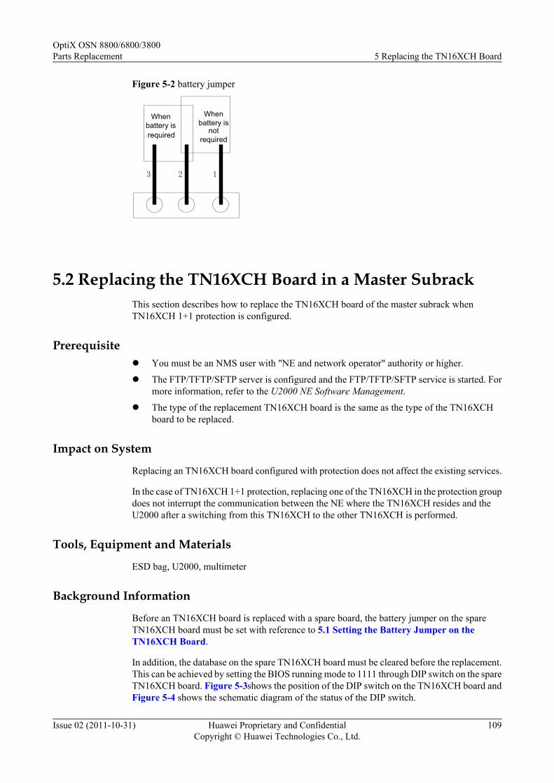
Figure 5-2 battery jumper
123
Whenbattery isrequired
Whenbattery is
notrequired
5.2 Replacing the TN16XCH Board in a Master SubrackThis section describes how to replace the TN16XCH board of the master subrack whenTN16XCH 1+1 protection is configured.
Prerequisitel You must be an NMS user with "NE and network operator" authority or higher.
l The FTP/TFTP/SFTP server is configured and the FTP/TFTP/SFTP service is started. Formore information, refer to the U2000 NE Software Management.
l The type of the replacement TN16XCH board is the same as the type of the TN16XCHboard to be replaced.
Impact on System
Replacing an TN16XCH board configured with protection does not affect the existing services.
In the case of TN16XCH 1+1 protection, replacing one of the TN16XCH in the protection groupdoes not interrupt the communication between the NE where the TN16XCH resides and theU2000 after a switching from this TN16XCH to the other TN16XCH is performed.
Tools, Equipment and Materials
ESD bag, U2000, multimeter
Background Information
Before an TN16XCH board is replaced with a spare board, the battery jumper on the spareTN16XCH board must be set with reference to 5.1 Setting the Battery Jumper on theTN16XCH Board.
In addition, the database on the spare TN16XCH board must be cleared before the replacement.This can be achieved by setting the BIOS running mode to 1111 through DIP switch on the spareTN16XCH board. Figure 5-3shows the position of the DIP switch on the TN16XCH board andFigure 5-4 shows the schematic diagram of the status of the DIP switch.
OptiX OSN 8800/6800/3800Parts Replacement 5 Replacing the TN16XCH Board
Issue 02 (2011-10-31) Huawei Proprietary and ConfidentialCopyright © Huawei Technologies Co., Ltd.
109

Figure 5-3 Position of the BIOS running mode DIP on the TN16XCH
CF Card
BatteryJumper
3 2 1CPU
J1SW1
OFF ON
BIOS Running Mode431 2
Figure 5-4 Setting the BIOS running mode to 1111
ON
OFF
1 2 43
The Lowest Site
The Highest Site
ON=1
OFF=0
Procedure
Step 1 Select a spare TN16XCH board as the replacement board. Ensure that the spare TN16XCH boardand the TN16XCH board to be replaced have the same name and type.
NOTEThe 1X3 jumper (namely, the battery jumper) on the TN16XCH board is used to enable or disable thepower supply from the battery. Ensure that pin 1 and pin 2 of this jumper are capped. Then, cap pin 2 andpin 3 on the jumper and use a multimeter to measure the battery voltage. If the voltage is lower than 3 V,the battery is not working. The TN16XCH board needs to be replaced.
Step 2 Review and record the current alarms on the NE. For more information, refer to "Querying theCurrent Alarms" of the Supporting Tasks.
OptiX OSN 8800/6800/3800Parts Replacement 5 Replacing the TN16XCH Board
Issue 02 (2011-10-31) Huawei Proprietary and ConfidentialCopyright © Huawei Technologies Co., Ltd.
110
Step 3 Back up the NE database to the NMS server. This is to record the NE database when theTN16XCH board is replaced for future reference.
1. In the Main Topology view, choose Administration > NE Software Management > NEData Backup/Restoration from the Main Menu.
2. Right click the device(s) that you want to backup in the NE View table.
NOTE
The Backup Information tab is unavailable when multiple devices are selected.
3. Select Backup... to open the Backup dialog.4. Select the option NMS Server or NMS Client to backup the selected device information.
NOTE
By default the NMS Server is selected. If the NMS Server is selected, the selected device informationis stored on the NMS server.
5. Optional: If the NMS Client is selected, click to select the location where the devicedata have to be backed up.
6. Click Start to start the backup operation for the selected device(s). On the NE View tabpage, the backup progress is displayed.
7. When the backup operation is successful, the NMS creates the dbf.pkg file in the NEName/yyyymmddhhmmss directory. "NEName" indicates the name of the NE, "yyyymmdd"indicates the date when the backup is created, and "hhmmss" indicates the time when thebackup is created.
Step 4 Follow the steps below to review the working state of the board to be replaced.
1. In the NE Explorer, click the NE and choose Configuration > Board 1+1 Protection fromthe Function Tree.
2. Click Query.
Step 5 If the board to be replaced is the active board, go to Step 6. Otherwise, go to Step 7.
Step 6 If the board to be replaced is the working board, follow the steps below to perform an active/standby switching on the U2000.
1. In the Main Topology, right-click the desire NE and click NE Explorer from the shortcutmenu. The NE Explorer window is displayed.
2. Choose Configuration > Board 1+1 Protection from the Function Tree.3. In Board 1+1 Protection, right-click the desired SCC Board 1+1 Protection. Select
Working/Protection Switching from the shortcut menu. Click OK in the windowdisplayed.
4. Click Query. If the Active Board is not the board to be replaced, the switching is successful.5. Query the alarms and performance events on the U2000. Check if services are normal. If
services are normal, there must be no new abnormal alarms or performances. The switchingis successful.
Step 7 Inform the onsite maintenance engineer and replace the board. For more information regardinghow to remove a board, refer to "Replacing a Board" of the Supporting Tasks.
Step 8 Set the DIP switch on the spare TN16XCH board so as to set the BIOS running mode and theninsert the TN16XCH board to the slot housing the original TN16XCH board. In this manner,the database on the new TN16XCH board is cleared.
OptiX OSN 8800/6800/3800Parts Replacement 5 Replacing the TN16XCH Board
Issue 02 (2011-10-31) Huawei Proprietary and ConfidentialCopyright © Huawei Technologies Co., Ltd.
111

1. Set the BIOS running mode of the spare TN16XCH board to 1111 to clear the database inthe flash memory. Figure 5-4 shows the settings of the DIP switch on the TN16XCH board.
2. Insert the spare TN16XCH board to the slot housing the original TN16XCH board.
NOTE
After the four jumpers are set and the TN16XCH board is inserted to the slot, wait for 15 minutes to allowthe database to be cleared.
Step 9 After the database on the new TN16XCH board is cleared, remove it. In addition, reset the DIPswitch to 0000 state which are shown in Step 8. After that, reinsert this TN16XCH board to theslot.
Step 10 Review the indicators of the new board. It takes 90 minutes for a board to work normally afterthe board is inserted. Ensure that the STAT indicator is steady green. If the indicator givesabnormal indication, you need to reinsert the board or replace the board again. For moreinformation regarding indicator definitions, refer to "Indicators" of the Hardware Description.
Step 11 Optional: Follow the steps below to switch the active/standby state of the SCCs back to theoriginal state.
1. In the Main Topology, right-click the desire NE and click NE Explorer from the shortcutmenu. The NE Explorer window is displayed.
2. Choose Configuration > Board 1+1 Protection from the Function Tree.
3. In Board 1+1 Protection, right-click SCC Board 1+1 Protection. Select RestoreWorking/Protection from the shortcut menu. Click OK in the window displayed.
NOTEAfter the new TN16XCH board is started, the system automatically backs up the data on the existingTN16XCH board to the new TN16XCH board. After the data is backed up, you can perform the precedingstep to initiate an active/standby switching.
Step 12 Check and set the other parameters on the U2000 to ensure that the parameter values of the newboard are the same as the original data.
1. Check the software information of the new SCC against the original data.
2. Synchronize the NE time with the NMS server time.
3. Check the NE alarm attribute data against the original data. The data include saving mode,reversion mode and delayed report.
4. Check the alarm suppression setting data against the original data.
5. Enable the NE performance monitoring.
6. Check whether the switching state is correct. Perform a switching test.
NOTEFor details to set these parameters, see iManager U2000 Operator Guide for NG WDM NE Management.
Step 13 Querying the current alarms of the NE by using the U2000.
1. In the Main Topology view, choose Fault > Browse Current Alarm from the Main Menu.
2. Click the Basic Setting and Alarm Source tabs in turn on the Filter dialog box to set thefilter conditions for the current alarms.
3. Click OK.
4. Record the current alarms of the NE.
OptiX OSN 8800/6800/3800Parts Replacement 5 Replacing the TN16XCH Board
Issue 02 (2011-10-31) Huawei Proprietary and ConfidentialCopyright © Huawei Technologies Co., Ltd.
112

NOTEYou can select the desired alarms and right-click to choose Save > Save Selected Records, or right-click to choose Save > Save All Records from the shortcut menu to save the current alarms of theNE.
NOTEAfter the TN16XCH is replaced, ensure that the monitoring of the POWER_FAIL alarm is enabled. If thePOWER_FAIL alarm occurs, and the alarm parameter is 0x5 0xff 0xff 0xff 0xff, the battery of theTN16XCH board is abnormal, determine if the jumper cap is correctly placed over the battery jumper. Ifyes, use a multimeter to measure the battery voltage. If the voltage is lower than 3 V, the battery is notworking. The board needs to be replaced.
CAUTIONThe standard voltage of the battery is 3.6 V. The battery is fixed on the board and cannot bereplaced.
----End
5.3 Replacing the TN16XCH Board in a Slave SubrackThis section describes how to replace an TN16XCH board in a slave subrack.
PrerequisiteYou must be an NMS user with "NE and network operator" authority or higher.
Impact on SystemReplacing the TN16XCH does not affect the existing services and system.
Tools, Equipment and MaterialsESD bag, U2000, multimeter
Background InformationBefore an TN16XCH board is replaced with a spare board, the battery jumper on the spareTN16XCH board must be set with reference to 5.1 Setting the Battery Jumper on theTN16XCH Board.
Procedure
Step 1 Select a spare board. Ensure the name, and the type of the spare board are the same as those ofthe original board.
NOTEThe 1X3 jumper inside the board is used to enable or disable the power supply from the battery. Ensurethat pin 1 and pin 2 on the battery jumper are capped. Then, cap pin 2 and pin 3 on the battery jumper anduse a multimeter to measure the battery voltage. If the voltage is lower than 3 V, it indicates that the batteryis not working. In this case, the TN16XCH board needs to be replaced.
OptiX OSN 8800/6800/3800Parts Replacement 5 Replacing the TN16XCH Board
Issue 02 (2011-10-31) Huawei Proprietary and ConfidentialCopyright © Huawei Technologies Co., Ltd.
113

Step 2 Review and record the current alarms on the NE. For more information, refer to "Querying theCurrent Alarms" of the Supporting Tasks.
Step 3 Follow the steps below to review the working state of the board to be replaced.
1. In the NE Explorer, click the NE and choose Configuration > Board 1+1 Protection fromthe Function Tree.
2. Click Query.
Step 4 If the board to be replaced is the active board, go to Step 5. Otherwise, go to Step 6.
Step 5 If the board to be replaced is the working board, follow the steps below to perform an active/standby switching on the U2000.
1. In the Main Topology, right-click the desire NE and click NE Explorer from the shortcutmenu. The NE Explorer window is displayed.
2. Choose Configuration > Board 1+1 Protection from the Function Tree.
3. In Board 1+1 Protection, right-click the desired SCC Board 1+1 Protection. SelectWorking/Protection Switching from the shortcut menu. Click OK in the windowdisplayed.
4. Click Query. If the Active Board is not the board to be replaced, the switching is successful.
5. Query the alarms and performance events on the U2000. Check if services are normal. Ifservices are normal, there must be no new abnormal alarms or performances. The switchingis successful.
Step 6 Inform the onsite maintenance engineer and replace the board. For more information regardinghow to remove a board, refer to "Replacing a Board" of the Supporting Tasks.
Step 7 Review the indicators of the new board. It takes ten minutes for a new board to work normallyafter insertion. Ensure that the STAT indicator is steady green. If the indicator gives abnormalindication, you need to reinsert the board, or replace the board again. For more informationregarding indicator definitions, refer to "Indicators" of the Hardware Description.
Step 8 Querying the current alarms of the NE by using the U2000.
1. In the Main Topology view, choose Fault > Browse Current Alarm from the Main Menu.
2. Click the Basic Setting and Alarm Source tabs in turn on the Filter dialog box to set thefilter conditions for the current alarms.
3. Click OK.
4. Record the current alarms of the NE.
NOTEYou can select the desired alarms and right-click to choose Save > Save Selected Records, or right-click to choose Save > Save All Records from the shortcut menu to save the current alarms of theNE.
NOTEAfter the TN16XCH is replaced, ensure that the monitoring of the POWER_FAIL alarm is enabled. If thePOWER_FAIL alarm occurs, and the alarm parameter is 0x5 0xff 0xff 0xff 0xff, the battery of theTN16XCH board is abnormal, determine if the jumper cap is correctly placed over the battery jumper. Ifyes, use a multimeter to measure the battery voltage. If the voltage is lower than 3 V, the battery is notworking. The board needs to be replaced.
OptiX OSN 8800/6800/3800Parts Replacement 5 Replacing the TN16XCH Board
Issue 02 (2011-10-31) Huawei Proprietary and ConfidentialCopyright © Huawei Technologies Co., Ltd.
114

CAUTIONThe standard voltage of the battery is 3.6 V. The battery is fixed on the board and cannot bereplaced.
----End
OptiX OSN 8800/6800/3800Parts Replacement 5 Replacing the TN16XCH Board
Issue 02 (2011-10-31) Huawei Proprietary and ConfidentialCopyright © Huawei Technologies Co., Ltd.
115

6 Replacing the SCC Board with One of aDifferent PCB Version
About This Chapter
This section describes how to replace an SCC board with one SCC board of a later PCB version.The replacement mainly involves the SCC boards for the OptiX OSN 8800 T32 and OptiX OSN6800.
6.1 Replacing the Protected SCC Board in a Master SubrackThis section describes how to replace the SCC board in a master subrack when SCC 1+1protection is configured.
6.2 Replacing the Unprotected SCC Board in a Master SubrackThis section describes how to replace an SCC board in a master subrack when no protection isconfigured for the SCC board.
6.3 Replacing the SCC Board in a Slave SubrackThis section describes how to replace an SCC board in a slave subrack.
OptiX OSN 8800/6800/3800Parts Replacement
6 Replacing the SCC Board with One of a Different PCBVersion
Issue 02 (2011-10-31) Huawei Proprietary and ConfidentialCopyright © Huawei Technologies Co., Ltd.
116
6.1 Replacing the Protected SCC Board in a Master SubrackThis section describes how to replace the SCC board in a master subrack when SCC 1+1protection is configured.
Prerequisitel You must be an NM user with "NE and network operator" authority or higher.l The FTP/TFTP/SFTP server is configured and the FTP/TFTP/SFTP service is started. For
details, see U2000 NE Software Management.l If the replacement board and the SCC board to be replaced are of different types, the two
SCC boards in the subrack must be replaced to ensure that the active and standby SCCboards are of the same type.
Impact on SystemThe replacement does not affect the existing services.
In the case of SCC 1+1 protection, replacing one of the SCC in the protection group does notinterrupt the communication between the NE where the SCC resides and the U2000 after aswitching from this SCC to the other SCC is performed.
Tools, Equipment, and MaterialsESD bag, U2000, multimeter
Background InformationBefore an SCC board is replaced with a spare board, the battery jumper on the spare SCC boardmust be set with reference to 4.1 Setting the Battery Jumper on the SCC.
You must clear the database on the spare SCC board before replacing the replacement board.You can clear the database by setting the BIOS running mode by using four jumpers on thereplacement SCC board. The figure below shows the four jumpers for setting the BIOS runningmode and the battery jumper on an SCC board. The four jumpers for setting the BIOS runningmode are arranged from high order to low order and identified as 04, 03, 02, and 01.
The setting of each of the four jumpers corresponds to a binary value, either 0 or 1. When ajumper is not capped, the setting corresponds to binary 0. When a jumper is capped, the settingcorresponds to binary 1. The settings of the four jumpers can be arranged in 16 combinations,representing 0 to 15 in the decimal system. The default setting of the four jumpers is 0000.
OptiX OSN 8800/6800/3800Parts Replacement
6 Replacing the SCC Board with One of a Different PCBVersion
Issue 02 (2011-10-31) Huawei Proprietary and ConfidentialCopyright © Huawei Technologies Co., Ltd.
117

Figure 6-1 Position of the BIOS running mode jumper on the TN11SCC
CPU
Battery jumper
CFCard
1
2
3
Battery jumper
BIOS Running Mode
01020304
OptiX OSN 8800/6800/3800Parts Replacement
6 Replacing the SCC Board with One of a Different PCBVersion
Issue 02 (2011-10-31) Huawei Proprietary and ConfidentialCopyright © Huawei Technologies Co., Ltd.
118
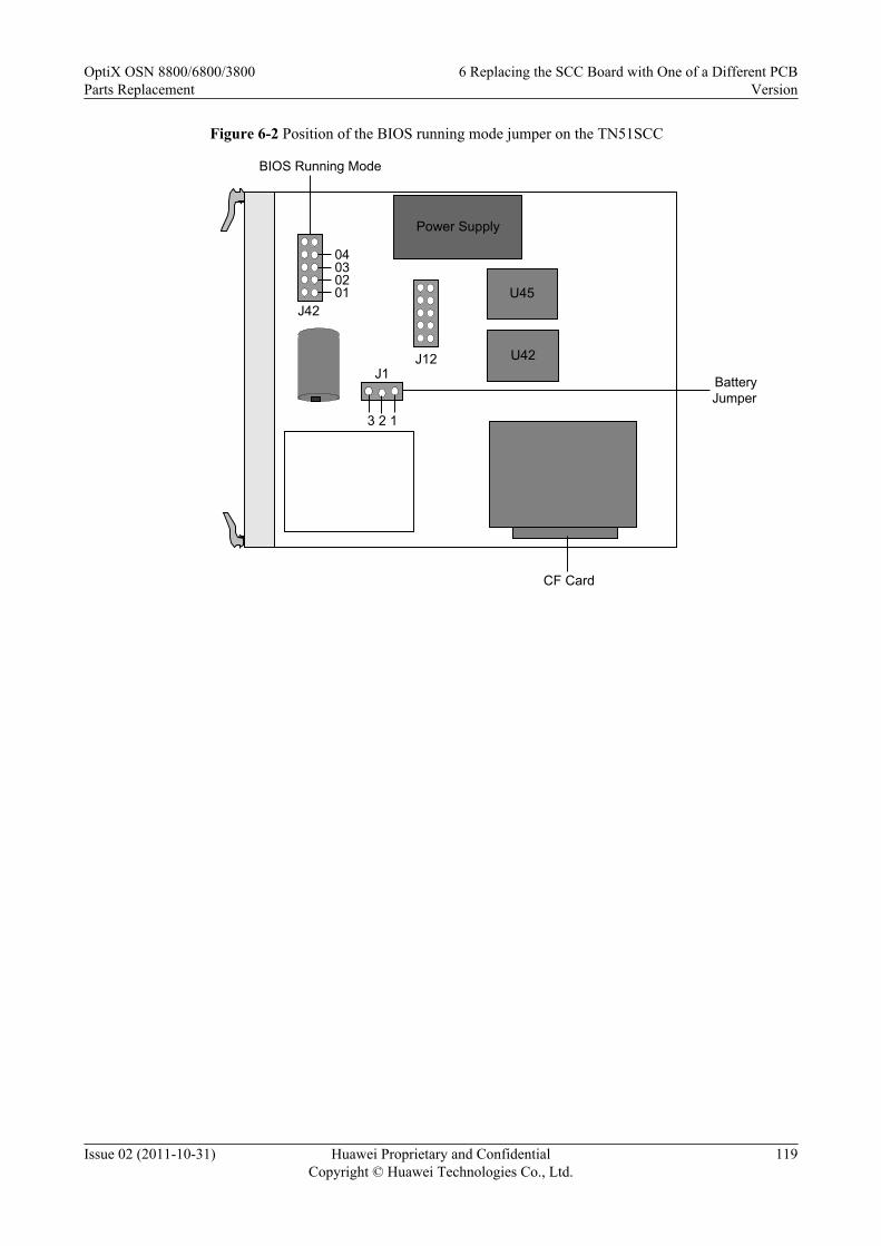
Figure 6-2 Position of the BIOS running mode jumper on the TN51SCC
Power Supply
U42J12
J42
3 2 1CPU
J1
U45
CF Card
BatteryJumper
01020304
BIOS Running Mode
OptiX OSN 8800/6800/3800Parts Replacement
6 Replacing the SCC Board with One of a Different PCBVersion
Issue 02 (2011-10-31) Huawei Proprietary and ConfidentialCopyright © Huawei Technologies Co., Ltd.
119
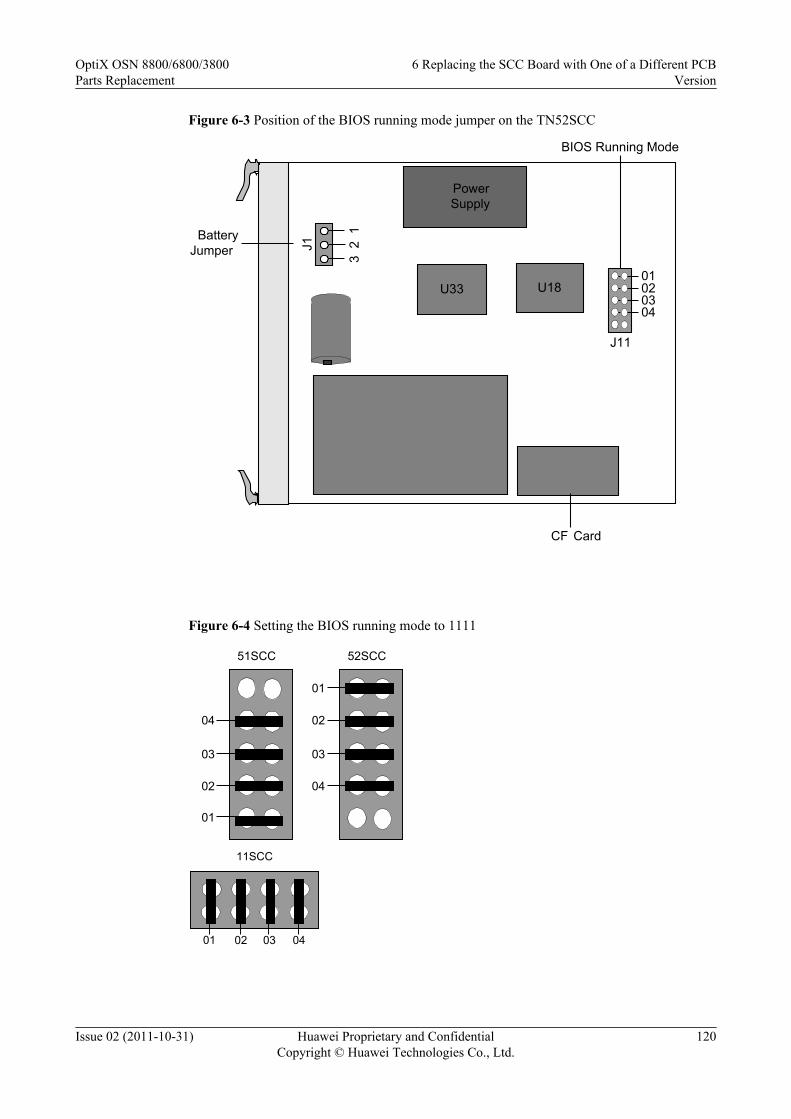
Figure 6-3 Position of the BIOS running mode jumper on the TN52SCC
PowerSupply
U33 U18
BatteryJumper 3
2 1
J1
CF Card
J11
01020304
BIOS Running Mode
Figure 6-4 Setting the BIOS running mode to 1111
01
02
03
04
52SCC
01
02
03
04
51SCC
0401 02 03
11SCC
OptiX OSN 8800/6800/3800Parts Replacement
6 Replacing the SCC Board with One of a Different PCBVersion
Issue 02 (2011-10-31) Huawei Proprietary and ConfidentialCopyright © Huawei Technologies Co., Ltd.
120

Procedure
Step 1 Select a spare SCC board as the replacement SCC board by referring to the following table.
Table 6-1 Version description of the SCC
Item Description
Replacement When ASON is not enabled, the TN51SCC board can be used to replacethe TN11SCC board. After replacement, the software of the new boardneeds to be upgraded. When ASON is enabled, The TN51SCC cannot beused to replace the TN11SCC.The TN52SCC can be used to replace the TN11SCC. Software upgrade isrequired for the replacement. The TN11SCC cannot be used to replace theTN51SCC and the TN52SCC.The TN52SCC can be used to replace the TN51SCC. The TN51SCC cannotbe used to replace the TN52SCC.The TNK2SCC board cannot be replaced with the TN51SCC or TN52SCCboard.NOTE
If two SCC boards need to be configured on the subrack, the active and standby SCCboards of the different types cannot be used at the same time.
NOTEThe 1X3 jumper (namely, the battery jumper) on the SCC board is used to enable or disable the powersupply from the battery. Make sure that pin 1 and pin 2 of this jumper are capped. Then, cap pin 2 and pin3 on the jumper and use a multimeter to measure the battery voltage. If the voltage is lower than 3 V, thebattery is out of work. The SCC board needs to be replaced.
Step 2 Review and record the current alarms on the NE. For more information, refer to "Querying theCurrent Alarms" of the Supporting Tasks.
Step 3 Back up the NE database to the NMS server. This is to record the NE database when the SCCboard is replaced for future reference.
1. In the Main Topology view, choose Administration > NE Software Management > NEData Backup/Restoration from the Main Menu.
2. Right click the device(s) that you want to backup in the NE View table.
NOTE
The Backup Information tab is unavailable when multiple devices are selected.
3. Select Backup... to open the Backup dialog.
4. Select the option NMS Server or NMS Client to backup the selected device information.
NOTE
By default the NMS Server is selected. If the NMS Server is selected, the selected device informationis stored on the NMS server.
5. Optional: If the NMS Client is selected, click to select the location where the devicedata have to be backed up.
OptiX OSN 8800/6800/3800Parts Replacement
6 Replacing the SCC Board with One of a Different PCBVersion
Issue 02 (2011-10-31) Huawei Proprietary and ConfidentialCopyright © Huawei Technologies Co., Ltd.
121
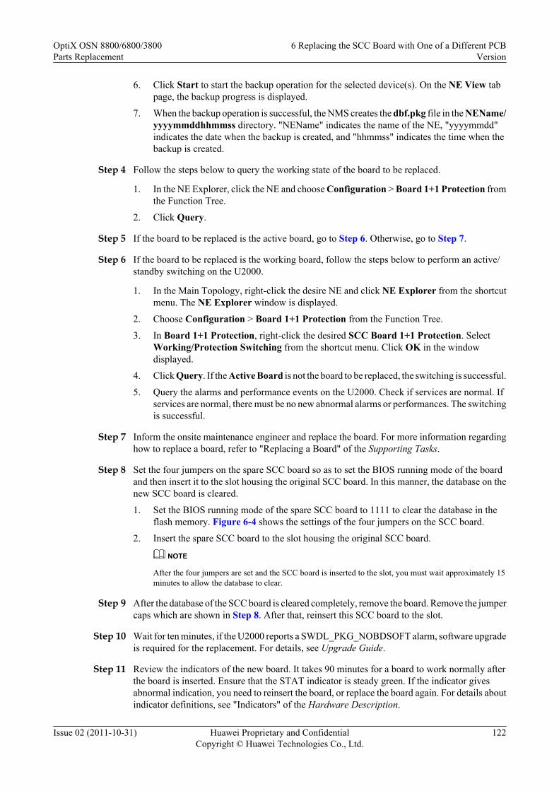
6. Click Start to start the backup operation for the selected device(s). On the NE View tabpage, the backup progress is displayed.
7. When the backup operation is successful, the NMS creates the dbf.pkg file in the NEName/yyyymmddhhmmss directory. "NEName" indicates the name of the NE, "yyyymmdd"indicates the date when the backup is created, and "hhmmss" indicates the time when thebackup is created.
Step 4 Follow the steps below to query the working state of the board to be replaced.
1. In the NE Explorer, click the NE and choose Configuration > Board 1+1 Protection fromthe Function Tree.
2. Click Query.
Step 5 If the board to be replaced is the active board, go to Step 6. Otherwise, go to Step 7.
Step 6 If the board to be replaced is the working board, follow the steps below to perform an active/standby switching on the U2000.
1. In the Main Topology, right-click the desire NE and click NE Explorer from the shortcutmenu. The NE Explorer window is displayed.
2. Choose Configuration > Board 1+1 Protection from the Function Tree.
3. In Board 1+1 Protection, right-click the desired SCC Board 1+1 Protection. SelectWorking/Protection Switching from the shortcut menu. Click OK in the windowdisplayed.
4. Click Query. If the Active Board is not the board to be replaced, the switching is successful.
5. Query the alarms and performance events on the U2000. Check if services are normal. Ifservices are normal, there must be no new abnormal alarms or performances. The switchingis successful.
Step 7 Inform the onsite maintenance engineer and replace the board. For more information regardinghow to replace a board, refer to "Replacing a Board" of the Supporting Tasks.
Step 8 Set the four jumpers on the spare SCC board so as to set the BIOS running mode of the boardand then insert it to the slot housing the original SCC board. In this manner, the database on thenew SCC board is cleared.
1. Set the BIOS running mode of the spare SCC board to 1111 to clear the database in theflash memory. Figure 6-4 shows the settings of the four jumpers on the SCC board.
2. Insert the spare SCC board to the slot housing the original SCC board.
NOTE
After the four jumpers are set and the SCC board is inserted to the slot, you must wait approximately 15minutes to allow the database to clear.
Step 9 After the database of the SCC board is cleared completely, remove the board. Remove the jumpercaps which are shown in Step 8. After that, reinsert this SCC board to the slot.
Step 10 Wait for ten minutes, if the U2000 reports a SWDL_PKG_NOBDSOFT alarm, software upgradeis required for the replacement. For details, see Upgrade Guide.
Step 11 Review the indicators of the new board. It takes 90 minutes for a board to work normally afterthe board is inserted. Ensure that the STAT indicator is steady green. If the indicator givesabnormal indication, you need to reinsert the board, or replace the board again. For details aboutindicator definitions, see "Indicators" of the Hardware Description.
OptiX OSN 8800/6800/3800Parts Replacement
6 Replacing the SCC Board with One of a Different PCBVersion
Issue 02 (2011-10-31) Huawei Proprietary and ConfidentialCopyright © Huawei Technologies Co., Ltd.
122

NOTE
After the new board works normally, the U2000 will report a WRG_BD_TYPE alarm.
Step 12 Set Replace Board Type on the U2000.
1. Double-click the optical NE icon in the Main Topology. Then, the Running Status of theoptical NE is displayed.
2. Select the desired NE. In the NE Panel tab, right-click the desired SCC board. A promptis displayed telling you that fibers on the board will be deleted. Click OK.
3. The dialog box of Replacement Board Type is displayed, select the name of the targetboard to be replaced within the Usable Board Type. Click OK.
4. After the replacement, a prompt appears asking you whether to immediately upload the NEdata. Click OK.
NOTE
If you click Cancel, the board is successfully upgraded, but you need to manually upload the NE datalater.
5. Click OK to confirm the uploading of the NE data again.
NOTE
If you click Cancel, the board is successfully upgraded, but you need to manually upload the NE datalater.
6. Click Close in the displayed Result dialog box.
NOTE
After changing the board type by setting Replace Board Type on the U2000, the WRG_BD_TYPE alarm iscleared.
Step 13 Optional: Follow the steps below to switch the active/standby state of the SCC boards back tothe original state.
1. In the Main Topology, right-click the desire NE and click NE Explorer from the shortcutmenu. The NE Explorer window is displayed.
2. Choose Configuration > Board 1+1 Protection from the Function Tree.
3. In Board 1+1 Protection, right-click SCC Board 1+1 Protection. Select RestoreWorking/Protection from the shortcut menu. Click OK in the window displayed.
NOTEAfter you start the new SCC board, the system automatically synchronizes the data between the existingSCC board and the new SCC board. After data backup completes, you can perform the preceding step toinitiate active/standby switching.
Step 14 Check and set the other parameters on the U2000 to ensure that the parameter values of the newboard are the same as the original data.
1. Check the software information of the new SCC against the original data.
2. Synchronize the NE time with the NMS server time.
3. Check the NE alarm attribute data against the original data. The data include saving mode,reversion mode and delayed report.
4. Check the alarm suppression setting data against the original data.
5. Enable the NE performance monitoring.
6. Check whether the switching state is correct. Perform a switching test.
OptiX OSN 8800/6800/3800Parts Replacement
6 Replacing the SCC Board with One of a Different PCBVersion
Issue 02 (2011-10-31) Huawei Proprietary and ConfidentialCopyright © Huawei Technologies Co., Ltd.
123

NOTEFor details to set these parameters, see iManager U2000 Operator Guide for NG WDM NE Management.
Step 15 Check the indicators of the new board. Ensure that the STAT indicator is steady on green. If theindicator gives abnormal indication, you need to reinsert the board, or replace the board again.For the indicator definitions, see "Indicators" of the Hardware Description.
Step 16 Querying the current alarms of the NE by using the U2000.
1. In the Main Topology view, choose Fault > Browse Current Alarm from the Main Menu.
2. Click the Basic Setting and Alarm Source tabs in turn on the Filter dialog box to set thefilter conditions for the current alarms.
3. Click OK.
4. Record the current alarms of the NE.
NOTEYou can select the desired alarms and right-click to choose Save > Save Selected Records, or right-click to choose Save > Save All Records from the shortcut menu to save the current alarms of theNE.
NOTEAfter replacing the SCC is replaced, ensure that the monitoring of the POWER_FAIL alarm is enabled. Ifthe POWER_FAIL alarm occurs, and the alarm parameter is 0x5 0xff 0xff 0xff 0xff, the battery of the SCCboard is abnormal, check whether the jumper cap is correctly placed over the battery jumper. If yes, use amultimeter to measure the battery voltage. If the voltage is lower than 3 V, the battery is out of work. Theboard must be replaced.
CAUTIONThe standard voltage of the battery is 3.6 V. The battery is fixed on the board and cannot bereplaced.
Step 17 Repeat the preceding steps to replace the other SCC board in the protection group and ensurethat the two SCC boards are of the same type after the replacement.
----End
6.2 Replacing the Unprotected SCC Board in a MasterSubrack
This section describes how to replace an SCC board in a master subrack when no protection isconfigured for the SCC board.
6.2.1 Replacing the SCC Board with the Database Backed Up to theNMS
Before replacing an SCC board, you can back up the NE database to the NMS. In this manner,you can restore the NE database from the NMS after replacing the SCC board.
OptiX OSN 8800/6800/3800Parts Replacement
6 Replacing the SCC Board with One of a Different PCBVersion
Issue 02 (2011-10-31) Huawei Proprietary and ConfidentialCopyright © Huawei Technologies Co., Ltd.
124

Prerequisitel You must be an NM user with "NE and network operator" authority or higher.l The FTP/TFTP/SFTP server is configured and the FTP/TFTP/SFTP service is started. For
details, see U2000 NE Software Management.
Impact on SystemReplacing the SCC board does not affect traditional services, but ASON services may be affectedfor a short time when configurations are restored by downloading the database.
The impact caused by replacing an SCC without protection is as follows:
l For the OptiX OSN 8800 T32, the SCC is housed in IU28 by default. If another board isinstalled in IU11, SCC 1+1 protection cannot be configured. In this case, replacing the SCCin an NE interrupts the communication between the NE and the U2000.
l For the OptiX OSN 6800, the SCC is housed in IU18 by default. When IU17 is occupiedby another board, SCC 1+1 protection cannot be configured. In this case, replacing the SCCin an NE interrupts the communication between the NE and the U2000.
Tools, Equipment, and MaterialsESD bag, U2000, multimeter, Web LCT
Background InformationBefore replacing an SCC board with a spare SCC board, set the battery jumper on the spare SCCboard with reference to 4.1 Setting the Battery Jumper on the SCC.
You must clear the database on the spare SCC board before replacing the replacement board.You can clear the database by setting the BIOS running mode by using four jumpers on thereplacement SCC board. The figure below shows the four jumpers for setting the BIOS runningmode and the battery jumper on an SCC board. The four jumpers for setting the BIOS runningmode are arranged from high order to low order and identified as 04, 03, 02, and 01.
The setting of each of the four jumpers corresponds to a binary value, either 0 or 1. When ajumper is not capped, the setting corresponds to binary 0. When a jumper is capped, the settingcorresponds to binary 1. The settings of the four jumpers can be arranged in 16 combinations,representing 0 to 15 in the decimal system. The default setting of the four jumpers is 0000.
OptiX OSN 8800/6800/3800Parts Replacement
6 Replacing the SCC Board with One of a Different PCBVersion
Issue 02 (2011-10-31) Huawei Proprietary and ConfidentialCopyright © Huawei Technologies Co., Ltd.
125

Figure 6-5 Position of the BIOS running mode jumper on the TN11SCC
CPU
Battery jumper
CFCard
1
2
3
Battery jumper
BIOS Running Mode
01020304
OptiX OSN 8800/6800/3800Parts Replacement
6 Replacing the SCC Board with One of a Different PCBVersion
Issue 02 (2011-10-31) Huawei Proprietary and ConfidentialCopyright © Huawei Technologies Co., Ltd.
126

Figure 6-6 Position of the BIOS running mode jumper on the TN51SCC
Power Supply
U42J12
J42
3 2 1CPU
J1
U45
CF Card
BatteryJumper
01020304
BIOS Running Mode
OptiX OSN 8800/6800/3800Parts Replacement
6 Replacing the SCC Board with One of a Different PCBVersion
Issue 02 (2011-10-31) Huawei Proprietary and ConfidentialCopyright © Huawei Technologies Co., Ltd.
127
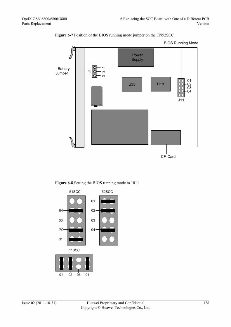
Figure 6-7 Position of the BIOS running mode jumper on the TN52SCC
PowerSupply
U33 U18
BatteryJumper 3
2 1
J1
CF Card
J11
01020304
BIOS Running Mode
Figure 6-8 Setting the BIOS running mode to 1011
01
02
03
04
52SCC
02
03
04
51SCC
01
0401 02 03
11SCC
OptiX OSN 8800/6800/3800Parts Replacement
6 Replacing the SCC Board with One of a Different PCBVersion
Issue 02 (2011-10-31) Huawei Proprietary and ConfidentialCopyright © Huawei Technologies Co., Ltd.
128

Figure 6-9 Setting the BIOS running mode to 1010
01
02
03
04
52SCC
01
02
03
04
51SCC
0401 02 03
11SCC
Precautions
CAUTIONl If the NE where the SCC to be replaced resides is an ASON NE, the Node ID of the NE
must be set according to the original data after the SCC is replaced. Otherwise, the NEdatabase and ASON service cannot be restored.
l Operations on the U2000 must be performed in the network management center.l Operations on the Web LCT must be performed on site.
Procedure
Step 1 Select a spare SCC board as the replacement SCC board by referring to the following table.
OptiX OSN 8800/6800/3800Parts Replacement
6 Replacing the SCC Board with One of a Different PCBVersion
Issue 02 (2011-10-31) Huawei Proprietary and ConfidentialCopyright © Huawei Technologies Co., Ltd.
129

Table 6-2 Version description of the SCC
Item Description
Replacement When ASON is not enabled, the TN51SCC board can be used to replacethe TN11SCC board. After replacement, the software of the new boardneeds to be upgraded. When ASON is enabled, The TN51SCC cannot beused to replace the TN11SCC.The TN52SCC can be used to replace the TN11SCC. Software upgrade isrequired for the replacement. The TN11SCC cannot be used to replace theTN51SCC and the TN52SCC.The TN52SCC can be used to replace the TN51SCC. The TN51SCC cannotbe used to replace the TN52SCC.The TNK2SCC board cannot be replaced with the TN51SCC or TN52SCCboard.NOTE
If two SCC boards need to be configured on the subrack, the active and standby SCCboards of the different types cannot be used at the same time.
NOTEThe 1X3 jumper (namely, the battery jumper) on the SCC board is used to enable or disable the powersupply from the battery. Make sure that pin 1 and pin 2 of this jumper are capped. Then, cap pin 2 and pin3 on the jumper and use a multimeter to measure the battery voltage. If the voltage is lower than 3 V, thebattery is out of work. The SCC board needs to be replaced.
Step 2 Review and record the current alarms on the NE. For more information, refer to "Querying theCurrent Alarms" of the Supporting Tasks.
Step 3 Back up the NE database to the NMS server. This is to record the NE database when the SCCboard is faulty for future reference.
1. In the Main Topology view, choose Administration > NE Software Management > NEData Backup/Restoration from the Main Menu.
2. Right click the device(s) that you want to backup in the NE View table.
NOTE
The Backup Information tab is unavailable when multiple devices are selected.
3. Select Backup... to open the Backup dialog.
4. Select the option NMS Server or NMS Client to backup the selected device information.
NOTE
By default the NMS Server is selected. If the NMS Server is selected, the selected device informationis stored on the NMS server.
5. Optional: If the NMS Client is selected, click to select the location where the devicedata have to be backed up.
6. Click Start to start the backup operation for the selected device(s). On the NE View tabpage, the backup progress is displayed.
7. When the backup operation is successful, the NMS creates the dbf.pkg file in the NEName/yyyymmddhhmmss directory. "NEName" indicates the name of the NE, "yyyymmdd"
OptiX OSN 8800/6800/3800Parts Replacement
6 Replacing the SCC Board with One of a Different PCBVersion
Issue 02 (2011-10-31) Huawei Proprietary and ConfidentialCopyright © Huawei Technologies Co., Ltd.
130

indicates the date when the backup is created, and "hhmmss" indicates the time when thebackup is created.
Step 4 Follow the steps below to query the system to obtain the user data of the NE.
1. In the NE Explorer, select an NE and choose Security > NE User Management from theFunction Tree.
2. Click Query.3. Record the NE user data returned by the system for future restoration of the NE user data.
Step 5 Follow the steps below to query the NE communication parameters.
1. Select the NE you just created, and click the NE Explorer.2. Select Communication > Communication Parameters from Function Tree.3. Record NE communication parameters such as the IP address and the subnet mask in case
you need them for parameter restoration.
Step 6 If the NE is an ASON NE, query and record the node ID of the NE.
1. In the NE Explorer, select an NE and choose ASON > ASON Feature Management fromthe Function Tree.
2. Click the Node ID Management tab.3. Click Query, and record the node ID.
Step 7 Inform the onsite maintenance engineer and remove the board. For details about how to removea board, see "Replacing a Board" of the Supporting Tasks.
Step 8 Set the four jumpers on the spare SCC board so as to set the BIOS running mode of the boardand then insert it to the slot housing the original SCC board. In this manner, the database on thenew SCC board is cleared.1. Set the BIOS running mode of the spare SCC board to 1011 to clear the database in the
flash memory. Figure 6-8 shows the settings of the four jumpers on the SCC board.2. Insert the spare SCC board to the slot housing the original SCC board.3. Wait for a few minutes until the PROG indicator is green and slowly flashes. Remove the
spare SCC board and then set its BIOS running mode to 1010 to clear the system parameterarea. For the settings of the four jumpers on the SCC board, see Figure 6-9. After that,reinsert the new SCC board to the slot.
NOTE
After the four BIOS jumpers are set and you install the SCC board in the slot, the PROG indicator on theSCC board is constantly green, which indicates that the database is being cleared. Wait for a few minutesuntil the PROG indicator blinks green, which indicates that the database is cleared completely.
Step 9 After the database of the SCC board is cleared completely, remove the board. Remove the jumpercaps which are shown in Step 8. After that, reinsert this SCC board to the slot.
Step 10 After the new SCC board is started, connect the Web LCT to the NE. Modify the NE attributeto restore the communication between the NE and the U2000.1. Disconnect the cables from the NM_ETH1 and NM_ETH2 ports (if connected). That is,
disconnect the NE from the computer where the U2000 (hereinafter the computer is referredto as U2000) is installed.
2. Connect the Web LCT to NM_ETH1.3. Set the IP address of the Web LCT to ensure that Web LCT is in the same IP subnet segment
as the NE IP address. If the IP address of the Web LCT and the NE IP address are in differentnetwork segments, the Web LCT cannot be connected to the NE.
OptiX OSN 8800/6800/3800Parts Replacement
6 Replacing the SCC Board with One of a Different PCBVersion
Issue 02 (2011-10-31) Huawei Proprietary and ConfidentialCopyright © Huawei Technologies Co., Ltd.
131

NOTEThe new board is initiated at factory, and the default IP subnet segment of the board is 129.9.*.*.
4. Log in the Web LCT with the user name admin, and the initial password admin.
Step 11 Create the NE by using the Web LCT.
1. Click NE Search > Advanced Search in the NE List. The Search NE dialog box isdisplayed.
2. Click Manage Domain. The Manage Domain Search dialog box is displayed.3. Click Add, and the New Domain dialog box is displayed.4. Set Domain Type to GNE IP Domain or GNE IP Address, and enter an IP address in the
Domain Address field.5. Click OK.
NOTEYou can repeat step 3 through 5 to add multiple search domains.
6. Click Cancel to exit the Manage Domain Search dialog box.7. Select appropriate network segment IP addresses within the Domain and click Search.
NOTE
l The NE search function searches out only the NEs in the specified network segment.
l When the search is in progress, you can click End Search.
8. After the search is complete, select an NE from the list and click Add NE. A promptmessage is displayed, indicating that the NE is successfully added. Click OK.
9. Select the NE that you want to log in and click NE Login in the lower right corner or right-click the NE and choose NE Login. In the NE Login dialog box that is displayed, enterlct and password in the User Name and Password fields, and then click OK.
TIP
You can select multiple NEs at a time by concurrently pressing Shift.
If you select the Use same user name and password to login check box, you can log in to multipleNEs at a time by entering the user name and password only in the first line.
If you select the Use the user name and password that was used last time check box, you do notneed to enter the use name and password and the system automatically uses the user name andpassword for login last time.
Step 12 Modify the NE IP based on the original information by using the Web LCT.
1. In the NE Explorer, select Communication > Communication Parameters fromFunction Tree.
2. Enter the IP Address, and click Apply.3. Click OK after the warning dialog box pops up.4. Click OK after the warning dialog box about communication interruption between NEs
pops up.5. Click Close after the Result dialog box is displayed.
NOTEIf the NE IP addresses before and after the modification are in different network segments, the Web LCT cannotbe connected to the NE. When this occurs, set the IP address of the Web LCT in the same network segment asthe NE IP address.
Step 13 Modify the gateway IP based on the original information by using the Web LCT.
OptiX OSN 8800/6800/3800Parts Replacement
6 Replacing the SCC Board with One of a Different PCBVersion
Issue 02 (2011-10-31) Huawei Proprietary and ConfidentialCopyright © Huawei Technologies Co., Ltd.
132

1. In the NE Explorer, Select Communication > Communication Parameters fromFunction Tree.
2. Enter the Gateway IP Address, and click Apply.3. Click OK after the Warning dialogue box pops up that prompts "The NE communication
parameters have been changed. Are you sure to send it? ".4. Click OK after the Warning dialogue box pops up that prompts "Incorrect operations will
interrupt the communication between NEs. Are you sure to continue? ".
Step 14 Modify the subnet mask based on the original information by using the Web LCT.
1. In the NE Explorer, Select Communication > Communication Parameters fromFunction Tree.
2. Enter the Subnet Mask, and click Apply.3. Click OK after the Warning dialogue box pops up that prompts "The NE communication
parameters have been changed. Are you sure to send it? ".4. Click OK after the Warning dialogue box pops up that prompts "Incorrect operations will
interrupt the communication between NEs. Are you sure to continue? ".
Step 15 Modify the NE ID and extended ID based on the original information by using the Web LCT.
1. In the NE Explorer, choose Configuration > NE Attribute from the Function Tree.2. Click Modify NE ID. In the Modify NE ID dialog box that is displayed, enter values in
the New ID and New Extended ID fields, and then click OK.3. A warning dialog box is displayed, click Yes. A dialog box indicating that the operation is
successful is displayed, click Close to complete changing the NE ID. At this time, the NEis unreachable.
Step 16 Check the NE communication parameters by using the Web LCT.
1. Select the NE you just created, and click the NE Explorer.2. Select Communication > Communication Parameters from Function Tree.3. Check that all NE communication parameters should be the same with the original ones.
Step 17 Create an NE's user by using the Web LCT.
1. In the NE Explorer, select the NE and choose Security > NE User Management from theFunction Tree.
2. Click Create and the Add NE User dialog box is displayed.3. Enter the NE user name in the NE User field.4. Select the User Level as needed.5. Enter the password in the New Password field and enter it again in the Confirm
Password field.
NOTE
You also need to set the Whether the password is allowed to be modified immediately parameter.
The password is a string of 6-16 characters. It can consist of letters, symbols and numerals, and mustcontain at least one letter and one numeral.
6. Click OK.7. Click Query, and the Operation Result dialog box is displayed. Click Close. All created
users of the NE are displayed in NE User Management Table.
Step 18 If the NE is an ASON NE, modify the node ID of the NE by using the Web LCT.
OptiX OSN 8800/6800/3800Parts Replacement
6 Replacing the SCC Board with One of a Different PCBVersion
Issue 02 (2011-10-31) Huawei Proprietary and ConfidentialCopyright © Huawei Technologies Co., Ltd.
133

1. In the NE Explorer, select an NE and choose ASON > ASON Feature Management fromthe Function Tree. Click the Node ID Management tab.
2. Click Query to view the current node ID of the NE.3. Double-click the Node ID field to enter a node ID for the NE.4. Click Apply. After you confirm the operation twice, a prompt appears telling you that the
operation was successful.
NOTE
You can also choose Configuration > WDM ASON > ASON Topology Management from the mainmenu and set the NE node ID.
Step 19 Recover the network connection of the NE.1. Remove the network cable which connected the NM_ETH1 port to the Web LCT.2. Connect the network cable removed in the Step 10.
NOTEAfter this procedure, you can use the original user name and password to access the NE by using theU2000.
NOTE
After recovering the network connection of the NE, the U2000 will report a WRG_BD_TYPE alarm.
Step 20 If the software version of the spare SCC board is different from the software version of the SCCboard to be replaced, go to Step 21, otherwise go to Step 22.
Step 21 Upgrade or downgrade the software of the spare SCC board. For details, see the UpgradeGuide. Ensure that the software version of the spare SCC board is consistent with that of theSCC board to be replaced.
Step 22 Restore the NE database from the NMS server.
1. In the Main Topology view, choose Administration > NE Software Management > NEData Backup/Restoration from the Main Menu.
2. Right click the device(s) that you want to recover in the NE View table.3. Select Recover... to open the Recover dialog.4. In the File Name drop-down list, select the file to be recovered. If the backup file is not
listed in the File Name drop-down list, select the file to be recovered, and turn to 22.6. Ifthe backup file is not listed in the File Name drop-down list, click Browse... to select thebackup file in the Select File dialog box, as shown below.
5. Select NMS Server or NMS Client to recover the backup file for the selected device(s).By default NMS Server is selected.l If NMS Server is selected, you need to select the appropriate backup file from the NMS
server. The selected backup file path is displayed in the File To Be Recovered field.
l If NMS Client is selected, you need to click to select the backup file from theNMS Client. The selected backup file path is displayed in the File To Be Recoveredfield.
6. Click OK.
NOTE
The selected backup file path from the NMS Server or NMS Client is displayed in the File Name drop-down list.
7. Click Start, the Operation Confirmation dialog box is displayed.
OptiX OSN 8800/6800/3800Parts Replacement
6 Replacing the SCC Board with One of a Different PCBVersion
Issue 02 (2011-10-31) Huawei Proprietary and ConfidentialCopyright © Huawei Technologies Co., Ltd.
134

8. In the Operation Confirmation dialog, click Yes to start the recover operation. Therecover operation status is displayed in the NE View table.
NOTE
You must activate the NE database within five minutes after restoring it.
CAUTIONDuring the process from backing up databases to restoring databases, do not modify the NEconfigurations to avoid database inconsistency.
Step 23 Activate the NE database.
1. In the Main Topology view, choose Administration > NE Software Management > NEData Backup/Restoration from the Main Menu.
2. Select the NE where the SCC that has been replaced resides in the NE View table.3. Right-click the NE, a pop-up menu is displayed.4. Select Activate Database..., and the Activate Database dialog box is displayed.
5. Optional: Click the icon in Deliver To Board Activate, and then this icon is changedto . Click Start to start the database activation process. The progress of the databaseactivation is displayed on the NE View tab.
NOTE
The operation on the U2000 may bring a service interruption.
Step 24 Set Replace Board Type on the U2000.
1. Double-click the optical NE icon in the Main Topology. Then, the Running Status of theoptical NE is displayed.
2. Select the desired NE. In the NE Panel tab, right-click the desired SCC board. A promptis displayed telling you that fibers on the board will be deleted. Click OK.
3. The dialog box of Replacement Board Type is displayed, select the name of the targetboard to be replaced within the Usable Board Type. Click OK.
4. After the replacement, a prompt appears asking you whether to immediately upload the NEdata. Click OK.
NOTE
If you click Cancel, the board is successfully upgraded, but you need to manually upload the NE datalater.
5. Click OK to confirm the uploading of the NE data again.NOTE
If you click Cancel, the board is successfully upgraded, but you need to manually upload the NE datalater.
6. Click Close in the displayed Result dialog box.
NOTE
After changing the board type by setting Replace Board Type on the U2000, the WRG_BD_TYPE alarm iscleared.
Step 25 Check and set the other parameters on the U2000 to ensure that the parameter values of the newboard are the same as the original data.
OptiX OSN 8800/6800/3800Parts Replacement
6 Replacing the SCC Board with One of a Different PCBVersion
Issue 02 (2011-10-31) Huawei Proprietary and ConfidentialCopyright © Huawei Technologies Co., Ltd.
135
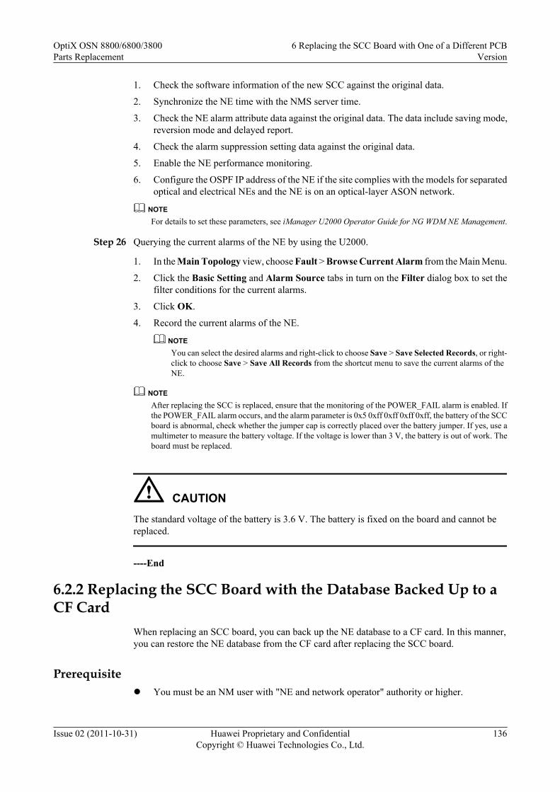
1. Check the software information of the new SCC against the original data.
2. Synchronize the NE time with the NMS server time.
3. Check the NE alarm attribute data against the original data. The data include saving mode,reversion mode and delayed report.
4. Check the alarm suppression setting data against the original data.
5. Enable the NE performance monitoring.
6. Configure the OSPF IP address of the NE if the site complies with the models for separatedoptical and electrical NEs and the NE is on an optical-layer ASON network.
NOTEFor details to set these parameters, see iManager U2000 Operator Guide for NG WDM NE Management.
Step 26 Querying the current alarms of the NE by using the U2000.
1. In the Main Topology view, choose Fault > Browse Current Alarm from the Main Menu.
2. Click the Basic Setting and Alarm Source tabs in turn on the Filter dialog box to set thefilter conditions for the current alarms.
3. Click OK.
4. Record the current alarms of the NE.
NOTEYou can select the desired alarms and right-click to choose Save > Save Selected Records, or right-click to choose Save > Save All Records from the shortcut menu to save the current alarms of theNE.
NOTEAfter replacing the SCC is replaced, ensure that the monitoring of the POWER_FAIL alarm is enabled. Ifthe POWER_FAIL alarm occurs, and the alarm parameter is 0x5 0xff 0xff 0xff 0xff, the battery of the SCCboard is abnormal, check whether the jumper cap is correctly placed over the battery jumper. If yes, use amultimeter to measure the battery voltage. If the voltage is lower than 3 V, the battery is out of work. Theboard must be replaced.
CAUTIONThe standard voltage of the battery is 3.6 V. The battery is fixed on the board and cannot bereplaced.
----End
6.2.2 Replacing the SCC Board with the Database Backed Up to aCF Card
When replacing an SCC board, you can back up the NE database to a CF card. In this manner,you can restore the NE database from the CF card after replacing the SCC board.
Prerequisitel You must be an NM user with "NE and network operator" authority or higher.
OptiX OSN 8800/6800/3800Parts Replacement
6 Replacing the SCC Board with One of a Different PCBVersion
Issue 02 (2011-10-31) Huawei Proprietary and ConfidentialCopyright © Huawei Technologies Co., Ltd.
136
Impact on SystemReplacing the SCC board does not affect traditional services, but ASON services may be affectedfor a short time when configurations are restored by downloading the database.
The impact caused by replacing an SCC without protection is as follows:
l For the OptiX OSN 8800 T32, the SCC is housed in IU28 by default. If another board isinstalled in IU11, SCC 1+1 protection cannot be configured. In this case, replacing the SCCin an NE interrupts the communication between the NE and the U2000.
l For the OptiX OSN 6800, the SCC is housed in IU18 by default. When IU17 is occupiedby another board, SCC 1+1 protection cannot be configured. In this case, replacing the SCCin an NE interrupts the communication between the NE and the U2000.
Tools, Equipment, and MaterialsESD bag, U2000, multimeter, Web LCT
Background InformationBefore replacing an SCC board with a spare SCC board, set the battery jumper on the spare SCCboard with reference to 4.1 Setting the Battery Jumper on the SCC.
You must clear the database on the spare SCC board before replacing the replacement board.You can clear the database by setting the BIOS running mode by using four jumpers on thereplacement SCC board. The figure below shows the four jumpers for setting the BIOS runningmode and the battery jumper on an SCC board. The four jumpers for setting the BIOS runningmode are arranged from high order to low order and identified as 04, 03, 02, and 01.
The setting of each of the four jumpers corresponds to a binary value, either 0 or 1. When ajumper is not capped, the setting corresponds to binary 0. When a jumper is capped, the settingcorresponds to binary 1. The settings of the four jumpers can be arranged in 16 combinations,representing 0 to 15 in the decimal system. The default setting of the four jumpers is 0000.
OptiX OSN 8800/6800/3800Parts Replacement
6 Replacing the SCC Board with One of a Different PCBVersion
Issue 02 (2011-10-31) Huawei Proprietary and ConfidentialCopyright © Huawei Technologies Co., Ltd.
137

Figure 6-10 Position of the BIOS running mode jumper on the TN11SCC
CPU
Battery jumper
CFCard
1
2
3
Battery jumper
BIOS Running Mode
01020304
OptiX OSN 8800/6800/3800Parts Replacement
6 Replacing the SCC Board with One of a Different PCBVersion
Issue 02 (2011-10-31) Huawei Proprietary and ConfidentialCopyright © Huawei Technologies Co., Ltd.
138
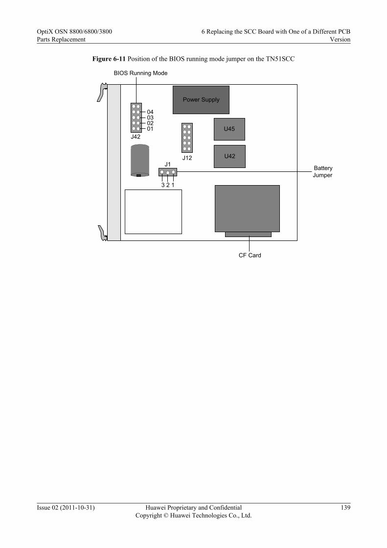
Figure 6-11 Position of the BIOS running mode jumper on the TN51SCC
Power Supply
U42J12
J42
3 2 1CPU
J1
U45
CF Card
BatteryJumper
01020304
BIOS Running Mode
OptiX OSN 8800/6800/3800Parts Replacement
6 Replacing the SCC Board with One of a Different PCBVersion
Issue 02 (2011-10-31) Huawei Proprietary and ConfidentialCopyright © Huawei Technologies Co., Ltd.
139

Figure 6-12 Position of the BIOS running mode jumper on the TN52SCC
PowerSupply
U33 U18
BatteryJumper 3
2 1
J1
CF Card
J11
01020304
BIOS Running Mode
Figure 6-13 Setting the BIOS running mode to 1011
01
02
03
04
52SCC
02
03
04
51SCC
01
0401 02 03
11SCC
OptiX OSN 8800/6800/3800Parts Replacement
6 Replacing the SCC Board with One of a Different PCBVersion
Issue 02 (2011-10-31) Huawei Proprietary and ConfidentialCopyright © Huawei Technologies Co., Ltd.
140

Figure 6-14 Setting the BIOS running mode to 1010
01
02
03
04
52SCC
01
02
03
04
51SCC
0401 02 03
11SCC
Precautions
CAUTIONl If the NE where the SCC to be replaced resides is an ASON NE, the Node ID of the NE must
be set according to the original data after the SCC is replaced. Otherwise, the ASON servicecannot be restored.
l After the database of the NE is restored on the CF card, the restoration must be completedwithin two hours after you install the replacement SCC is installed. If you wait more thantwo hours to restore the database of the NE on the CF card, the data automatically saved onthe NE overwrites the original data stored on the CF card. If the original data is overwritten,the original database of the NE cannot be restored.
l Operations on the U2000 must be performed in the network management center.l Operations on the Web LCT must be performed on site.
Procedure
Step 1 Select a spare SCC board as the replacement SCC board by referring to the following table.
OptiX OSN 8800/6800/3800Parts Replacement
6 Replacing the SCC Board with One of a Different PCBVersion
Issue 02 (2011-10-31) Huawei Proprietary and ConfidentialCopyright © Huawei Technologies Co., Ltd.
141

Table 6-3 Version description of the SCC
Item Description
Replacement When ASON is not enabled, the TN51SCC board can be used to replacethe TN11SCC board. After replacement, the software of the new boardneeds to be upgraded. When ASON is enabled, The TN51SCC cannot beused to replace the TN11SCC.The TN52SCC can be used to replace the TN11SCC. Software upgrade isrequired for the replacement. The TN11SCC cannot be used to replace theTN51SCC and the TN52SCC.The TN52SCC can be used to replace the TN51SCC. The TN51SCC cannotbe used to replace the TN52SCC.The TNK2SCC board cannot be replaced with the TN51SCC or TN52SCCboard.NOTE
If two SCC boards need to be configured on the subrack, the active and standby SCCboards of the different types cannot be used at the same time.
NOTEThe 1X3 jumper (namely, the battery jumper) on the SCC board is used to enable or disable the powersupply from the battery. Make sure that pin 1 and pin 2 of this jumper are capped. Then, cap pin 2 and pin3 on the jumper and use a multimeter to measure the battery voltage. If the voltage is lower than 3 V, thebattery is out of work. The SCC board needs to be replaced.
Step 2 Review and record the current alarms on the NE. For more information, refer to "Querying theCurrent Alarms" of the Supporting Tasks.
Step 3 Backup the database on the U2000.
1. In the Main Topology view, choose Configuration > NE Configuration DataManagement from the Main Menu, and the NE Configuration Data Managementinterface is displayed.
2. In the Object Tree, select an NE and click .
3. Select one or more NEs in the NE Configuration.
4. Click Back Up NE Data and then choose Manually Back Up Database to CF Card.
5. Click OK in the confirmation dialog box.
6. Click Close in the Operation Result dialog box is displayed.
Step 4 Four minutes later, query the system to obtain the user data of the NE following the steps below.
1. In the NE Explorer, select an NE and choose Security > NE User Management from theFunction Tree.
2. Click Query.
3. Record the NE user data returned by the system for future restoration of the NE user data.
Step 5 Follow the steps below to query the NE communication parameters.
1. Select the NE you just created, and click the NE Explorer.
2. Select Communication > Communication Parameters from Function Tree.
OptiX OSN 8800/6800/3800Parts Replacement
6 Replacing the SCC Board with One of a Different PCBVersion
Issue 02 (2011-10-31) Huawei Proprietary and ConfidentialCopyright © Huawei Technologies Co., Ltd.
142

3. Record NE communication parameters such as the IP address and the subnet mask in caseyou need them for parameter restoration.
Step 6 If the NE is an ASON NE, query and record the node ID of the NE.
1. In the NE Explorer, select an NE and choose ASON > ASON Feature Management fromthe Function Tree.
2. Click the Node ID Management tab.
3. Click Query, and record the node ID.
Step 7 Remove the SCC board to be replaced. For details, see "Replacing a Board" of the SupportingTasks.
Step 8 On the SCC board that has been removed, hold the CF card and pull the card out of the CF cardslot. Put the SCC into an ESD bag.
NOTE
Keep the CF card because it is required for NE data restoration.
Step 9 Set the four jumpers on the spare SCC board so as to set the BIOS running mode of the boardand then insert it to the slot housing the original SCC board. In this manner, the database on thenew SCC board is cleared.
1. Set the BIOS running mode of the spare SCC board to 1011 to clear the database in theflash memory. Figure 6-13 shows the settings of the four jumpers on the SCC board.
2. Insert the spare SCC board to the slot housing the original SCC board.
3. Wait for a few minutes until the PROG indicator is green and slowly flashes. Remove thespare SCC board and then set its BIOS running mode to 1010 to clear the system parameterarea. For the settings of the four jumpers on the SCC board, see Figure 6-14. After that,reinsert the new SCC board to the slot.
NOTE
After the four jumpers are set and the SCC board is inserted to the slot, the PROG indicator on the SCCboard is constantly green, which indicates that the database is being cleared. Wait for a few minutes untilthe PROG indicator is green and flashes, which indicates that the database cleared completely.
Step 10 After the database of the SCC board is cleared completely, remove the board. Remove the jumpercaps which are shown in Step 9. After that, reinsert this SCC board to the slot.
Step 11 After the new SCC board is started, connect the Web LCT to the NE. Modify the NE attributeto restore the communication between the NE and the U2000.
1. Disconnect the cables from the NM_ETH1 and NM_ETH2 ports (if connected). That is,disconnect the NE from the computer where the U2000 (hereinafter the computer is referredto as U2000) is installed.
2. Connect the Web LCT to NM_ETH1.
3. Set the IP address of the Web LCT to ensure that Web LCT is in the same IP subnet segmentas the NE IP address. If the IP address of the Web LCT and the NE IP address are in differentnetwork segments, the Web LCT cannot be connected to the NE.
NOTEThe new board is initiated at factory, and the default IP subnet segment of the board is 129.9.*.*.
4. Log in the Web LCT with the user name admin, and the initial password admin.
Step 12 Create the NE by using the Web LCT.
OptiX OSN 8800/6800/3800Parts Replacement
6 Replacing the SCC Board with One of a Different PCBVersion
Issue 02 (2011-10-31) Huawei Proprietary and ConfidentialCopyright © Huawei Technologies Co., Ltd.
143

1. Click NE Search > Advanced Search in the NE List. The Search NE dialog box isdisplayed.
2. Click Manage Domain. The Manage Domain Search dialog box is displayed.3. Click Add, and the New Domain dialog box is displayed.4. Set Domain Type to GNE IP Domain or GNE IP Address, and enter an IP address in the
Domain Address field.5. Click OK.
NOTEYou can repeat step 3 through 5 to add multiple search domains.
6. Click Cancel to exit the Manage Domain Search dialog box.7. Select appropriate network segment IP addresses within the Domain and click Search.
NOTE
l The NE search function searches out only the NEs in the specified network segment.
l When the search is in progress, you can click End Search.
8. After the search is complete, select an NE from the list and click Add NE. A promptmessage is displayed, indicating that the NE is successfully added. Click OK.
9. Select the NE that you want to log in and click NE Login in the lower right corner or right-click the NE and choose NE Login. In the NE Login dialog box that is displayed, enterlct and password in the User Name and Password fields, and then click OK.
TIP
You can select multiple NEs at a time by concurrently pressing Shift.
If you select the Use same user name and password to login check box, you can log in to multipleNEs at a time by entering the user name and password only in the first line.
If you select the Use the user name and password that was used last time check box, you do notneed to enter the use name and password and the system automatically uses the user name andpassword for login last time.
Step 13 Modify the NE IP based on the original information by using the Web LCT.
1. In the NE Explorer, select Communication > Communication Parameters fromFunction Tree.
2. Enter the IP Address, and click Apply.3. Click OK after the warning dialog box pops up.4. Click OK after the warning dialog box about communication interruption between NEs
pops up.5. Click Close after the Result dialog box is displayed.
NOTEIf the NE IP addresses before and after the modification are in different network segments, the Web LCT cannotbe connected to the NE. When this occurs, set the IP address of the Web LCT in the same network segment asthe NE IP address.
Step 14 Modify the gateway IP based on the original information by using the Web LCT.
1. In the NE Explorer, Select Communication > Communication Parameters fromFunction Tree.
2. Enter the Gateway IP Address, and click Apply.3. Click OK after the Warning dialogue box pops up that prompts "The NE communication
parameters have been changed. Are you sure to send it? ".
OptiX OSN 8800/6800/3800Parts Replacement
6 Replacing the SCC Board with One of a Different PCBVersion
Issue 02 (2011-10-31) Huawei Proprietary and ConfidentialCopyright © Huawei Technologies Co., Ltd.
144

4. Click OK after the Warning dialogue box pops up that prompts "Incorrect operations willinterrupt the communication between NEs. Are you sure to continue? ".
Step 15 Modify the subnet mask based on the original information by using the Web LCT.
1. In the NE Explorer, Select Communication > Communication Parameters fromFunction Tree.
2. Enter the Subnet Mask, and click Apply.3. Click OK after the Warning dialogue box pops up that prompts "The NE communication
parameters have been changed. Are you sure to send it? ".4. Click OK after the Warning dialogue box pops up that prompts "Incorrect operations will
interrupt the communication between NEs. Are you sure to continue? ".
Step 16 Modify the NE ID and extended ID based on the original information by using the Web LCT.
1. In the NE Explorer, choose Configuration > NE Attribute from the Function Tree.2. Click Modify NE ID. In the Modify NE ID dialog box that is displayed, enter values in
the New ID and New Extended ID fields, and then click OK.3. A warning dialog box is displayed, click Yes. A dialog box indicating that the operation is
successful is displayed, click Close to complete changing the NE ID. At this time, the NEis unreachable.
Step 17 Check the NE communication parameters by using the Web LCT.
1. Select the NE you just created, and click the NE Explorer.2. Select Communication > Communication Parameters from Function Tree.3. Check that all NE communication parameters should be the same with the original ones.
Step 18 Create an NE's user by using the Web LCT.
1. In the NE Explorer, select the NE and choose Security > NE User Management from theFunction Tree.
2. Click Create and the Add NE User dialog box is displayed.3. Enter the NE user name in the NE User field.4. Select the User Level as needed.5. Enter the password in the New Password field and enter it again in the Confirm
Password field.
NOTE
You also need to set the Whether the password is allowed to be modified immediately parameter.
The password is a string of 6-16 characters. It can consist of letters, symbols and numerals, and mustcontain at least one letter and one numeral.
6. Click OK.7. Click Query, and the Operation Result dialog box is displayed. Click Close. All created
users of the NE are displayed in NE User Management Table.
Step 19 If the NE is an ASON NE, modify the node ID of the NE by using the Web LCT.
1. In the NE Explorer, select an NE and choose ASON > ASON Feature Management fromthe Function Tree. Click the Node ID Management tab.
2. Click Query to view the current node ID of the NE.3. Double-click the Node ID field to enter a node ID for the NE.
OptiX OSN 8800/6800/3800Parts Replacement
6 Replacing the SCC Board with One of a Different PCBVersion
Issue 02 (2011-10-31) Huawei Proprietary and ConfidentialCopyright © Huawei Technologies Co., Ltd.
145
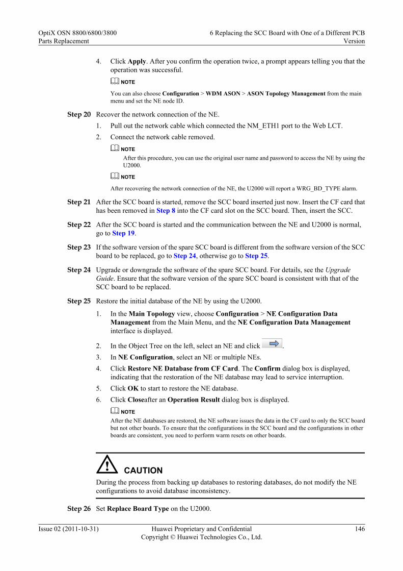
4. Click Apply. After you confirm the operation twice, a prompt appears telling you that theoperation was successful.
NOTE
You can also choose Configuration > WDM ASON > ASON Topology Management from the mainmenu and set the NE node ID.
Step 20 Recover the network connection of the NE.1. Pull out the network cable which connected the NM_ETH1 port to the Web LCT.2. Connect the network cable removed.
NOTEAfter this procedure, you can use the original user name and password to access the NE by using theU2000.
NOTE
After recovering the network connection of the NE, the U2000 will report a WRG_BD_TYPE alarm.
Step 21 After the SCC board is started, remove the SCC board inserted just now. Insert the CF card thathas been removed in Step 8 into the CF card slot on the SCC board. Then, insert the SCC.
Step 22 After the SCC board is started and the communication between the NE and U2000 is normal,go to Step 19.
Step 23 If the software version of the spare SCC board is different from the software version of the SCCboard to be replaced, go to Step 24, otherwise go to Step 25.
Step 24 Upgrade or downgrade the software of the spare SCC board. For details, see the UpgradeGuide. Ensure that the software version of the spare SCC board is consistent with that of theSCC board to be replaced.
Step 25 Restore the initial database of the NE by using the U2000.
1. In the Main Topology view, choose Configuration > NE Configuration DataManagement from the Main Menu, and the NE Configuration Data Managementinterface is displayed.
2. In the Object Tree on the left, select an NE and click .3. In NE Configuration, select an NE or multiple NEs.4. Click Restore NE Database from CF Card. The Confirm dialog box is displayed,
indicating that the restoration of the NE database may lead to service interruption.5. Click OK to start to restore the NE database.6. Click Closeafter an Operation Result dialog box is displayed.
NOTEAfter the NE databases are restored, the NE software issues the data in the CF card to only the SCC boardbut not other boards. To ensure that the configurations in the SCC board and the configurations in otherboards are consistent, you need to perform warm resets on other boards.
CAUTIONDuring the process from backing up databases to restoring databases, do not modify the NEconfigurations to avoid database inconsistency.
Step 26 Set Replace Board Type on the U2000.
OptiX OSN 8800/6800/3800Parts Replacement
6 Replacing the SCC Board with One of a Different PCBVersion
Issue 02 (2011-10-31) Huawei Proprietary and ConfidentialCopyright © Huawei Technologies Co., Ltd.
146

1. Double-click the optical NE icon in the Main Topology. Then, the Running Status of theoptical NE is displayed.
2. Select the desired NE. In the NE Panel tab, right-click the desired SCC board. A promptis displayed telling you that fibers on the board will be deleted. Click OK.
3. The dialog box of Replacement Board Type is displayed, select the name of the targetboard to be replaced within the Usable Board Type. Click OK.
4. After the replacement, a prompt appears asking you whether to immediately upload the NEdata. Click OK.
NOTE
If you click Cancel, the board is successfully upgraded, but you need to manually upload the NE datalater.
5. Click OK to confirm the uploading of the NE data again.
NOTE
If you click Cancel, the board is successfully upgraded, but you need to manually upload the NE datalater.
6. Click Close in the displayed Result dialog box.
NOTE
After changing the board type by setting Replace Board Type on the U2000, the WRG_BD_TYPE alarm iscleared.
Step 27 Check and set the other parameters on the U2000 to ensure that the parameter values of the newboard are the same as the original data.
1. Check the software information of the new SCC against the original data.
2. Synchronize the NE time with the NMS server time.
3. Check the NE alarm attribute data against the original data. The data include saving mode,reversion mode and delayed report.
4. Check the alarm suppression setting data against the original data.
5. Enable the NE performance monitoring.
6. Configure the OSPF IP address of the NE if the site complies with the models for separatedoptical and electrical NEs and the NE is on an optical-layer ASON network.
NOTEFor details to set these parameters, see iManager U2000 Operator Guide for NG WDM NE Management.
Step 28 Querying the current alarms of the NE by using the U2000.
1. In the Main Topology view, choose Fault > Browse Current Alarm from the Main Menu.
2. Click the Basic Setting and Alarm Source tabs in turn on the Filter dialog box to set thefilter conditions for the current alarms.
3. Click OK.
4. Record the current alarms of the NE.
NOTEYou can select the desired alarms and right-click to choose Save > Save Selected Records, or right-click to choose Save > Save All Records from the shortcut menu to save the current alarms of theNE.
OptiX OSN 8800/6800/3800Parts Replacement
6 Replacing the SCC Board with One of a Different PCBVersion
Issue 02 (2011-10-31) Huawei Proprietary and ConfidentialCopyright © Huawei Technologies Co., Ltd.
147

NOTEAfter replacing the SCC is replaced, ensure that the monitoring of the POWER_FAIL alarm is enabled. Ifthe POWER_FAIL alarm occurs, and the alarm parameter is 0x5 0xff 0xff 0xff 0xff, the battery of the SCCboard is abnormal, check whether the jumper cap is correctly placed over the battery jumper. If yes, use amultimeter to measure the battery voltage. If the voltage is lower than 3 V, the battery is out of work. Theboard must be replaced.
CAUTIONThe standard voltage of the battery is 3.6 V. The battery is fixed on the board and cannot bereplaced.
----End
6.2.3 Replacing the SCC Board After Configuring SCC 1+1Protection
When replacing an SCC board, you can configure protection for the SCC board if the slot forhousing the standby SCC board is not occupied by a service board.
Prerequisitel You must be an NM user with "NE and network operator" authority or higher.l The FTP/TFTP/SFTP server is configured and the FTP/TFTP/SFTP service is started. For
details, see U2000 NE Software Management.
Impact on SystemThe replacement does not affect the existing services.
The impact caused by replacing an SCC without protection is as follows:
l For the OptiX OSN 8800 T32, the SCC is housed in IU28 by default. When IU11 is notoccupied by another board, it is available for another SCC to implement 1+1 protectionwith the SCC in IU28. In this case, replacing one of the SCC in the protection group doesnot interrupt the communication between the NE where the SCC resides and the U2000after a switching from this SCC to the other SCC is performed.
l For the OptiX OSN 6800, the SCC is housed in IU18 by default. When IU17 is not occupiedby another board, it is available for another SCC to implement 1+1 protection with the SCCin IU18. In this case, replacing one of the SCC in the protection group does not interruptthe communication between the NE where the SCC resides and the U2000 after a switchingfrom this SCC to the other SCC is performed.
Tools, Equipment, and MaterialsESD bag, U2000, multimeter, Web LCT
Background InformationBefore replacing an SCC board with a spare SCC board, set the battery jumper on the spare SCCboard with reference to 4.1 Setting the Battery Jumper on the SCC.
OptiX OSN 8800/6800/3800Parts Replacement
6 Replacing the SCC Board with One of a Different PCBVersion
Issue 02 (2011-10-31) Huawei Proprietary and ConfidentialCopyright © Huawei Technologies Co., Ltd.
148

You must clear the database on the spare SCC board before replacing the replacement board.You can clear the database by setting the BIOS running mode by using four jumpers on thereplacement SCC board. The figure below shows the four jumpers for setting the BIOS runningmode and the battery jumper on an SCC board. The four jumpers for setting the BIOS runningmode are arranged from high order to low order and identified as 04, 03, 02, and 01.
The setting of each of the four jumpers corresponds to a binary value, either 0 or 1. When ajumper is not capped, the setting corresponds to binary 0. When a jumper is capped, the settingcorresponds to binary 1. The settings of the four jumpers can be arranged in 16 combinations,representing 0 to 15 in the decimal system. The default setting of the four jumpers is 0000.
Figure 6-15 Position of the BIOS running mode jumper on the TN11SCC
CPU
Battery jumper
CFCard
1
2
3
Battery jumper
BIOS Running Mode
01020304
OptiX OSN 8800/6800/3800Parts Replacement
6 Replacing the SCC Board with One of a Different PCBVersion
Issue 02 (2011-10-31) Huawei Proprietary and ConfidentialCopyright © Huawei Technologies Co., Ltd.
149

Figure 6-16 Position of the BIOS running mode jumper on the TN51SCC
Power Supply
U42J12
J42
3 2 1CPU
J1
U45
CF Card
BatteryJumper
01020304
BIOS Running Mode
OptiX OSN 8800/6800/3800Parts Replacement
6 Replacing the SCC Board with One of a Different PCBVersion
Issue 02 (2011-10-31) Huawei Proprietary and ConfidentialCopyright © Huawei Technologies Co., Ltd.
150

Figure 6-17 Position of the BIOS running mode jumper on the TN52SCC
PowerSupply
U33 U18
BatteryJumper 3
2 1
J1
CF Card
J11
01020304
BIOS Running Mode
Figure 6-18 Setting the BIOS running mode to 1111
01
02
03
04
52SCC
01
02
03
04
51SCC
0401 02 03
11SCC
OptiX OSN 8800/6800/3800Parts Replacement
6 Replacing the SCC Board with One of a Different PCBVersion
Issue 02 (2011-10-31) Huawei Proprietary and ConfidentialCopyright © Huawei Technologies Co., Ltd.
151

Precautions
CAUTIONl If the NE where the SCC to be replaced resides is an ASON NE, the Node ID of the NE
must be set according to the original data after the SCC is replaced. Otherwise, the NEdatabase and ASON service cannot be restored.
l Operations on the U2000 must be performed in the network management center.l Operations on the Web LCT must be performed on site.
Procedure
Step 1 Select a spare SCC board as the replacement SCC board by referring to the following table.
Table 6-4 Version description of the SCC
Item Description
Replacement When ASON is not enabled, the TN51SCC board can be used to replacethe TN11SCC board. After replacement, the software of the new boardneeds to be upgraded. When ASON is enabled, The TN51SCC cannot beused to replace the TN11SCC.The TN52SCC can be used to replace the TN11SCC. Software upgrade isrequired for the replacement. The TN11SCC cannot be used to replace theTN51SCC and the TN52SCC.The TN52SCC can be used to replace the TN51SCC. The TN51SCC cannotbe used to replace the TN52SCC.The TNK2SCC board cannot be replaced with the TN51SCC or TN52SCCboard.NOTE
If two SCC boards need to be configured on the subrack, the active and standby SCCboards of the different types cannot be used at the same time.
NOTEThe 1X3 jumper (namely, the battery jumper) on the SCC board is used to enable or disable the powersupply from the battery. Make sure that pin 1 and pin 2 of this jumper are capped. Then, cap pin 2 and pin3 on the jumper and use a multimeter to measure the battery voltage. If the voltage is lower than 3 V, thebattery is out of work. The SCC board needs to be replaced.
Step 2 Back up the NE database to the NMS server. This is to record the NE database when the SCCboard is replaced for future reference.
1. In the Main Topology view, choose Administration > NE Software Management > NEData Backup/Restoration from the Main Menu.
2. Right click the device(s) that you want to backup in the NE View table.
NOTE
The Backup Information tab is unavailable when multiple devices are selected.
OptiX OSN 8800/6800/3800Parts Replacement
6 Replacing the SCC Board with One of a Different PCBVersion
Issue 02 (2011-10-31) Huawei Proprietary and ConfidentialCopyright © Huawei Technologies Co., Ltd.
152

3. Select Backup... to open the Backup dialog.4. Select the option NMS Server or NMS Client to backup the selected device information.
NOTE
By default the NMS Server is selected. If the NMS Server is selected, the selected device informationis stored on the NMS server.
5. Optional: If the NMS Client is selected, click to select the location where the devicedata have to be backed up.
6. Click Start to start the backup operation for the selected device(s). On the NE View tabpage, the backup progress is displayed.
7. When the backup operation is successful, the NMS creates the dbf.pkg file in the NEName/yyyymmddhhmmss directory. "NEName" indicates the name of the NE, "yyyymmdd"indicates the date when the backup is created, and "hhmmss" indicates the time when thebackup is created.
Step 3 Set the four jumpers on the spare SCC board so as to set the BIOS running mode of the boardand then insert it to the specified slot for a standby SCC board. In this manner, the database onthe new SCC board is cleared.
NOTE
After inserting the spare SCC board to the specified slot for a standby SCC board, you need to add a correspondinglogical board on the U2000. Then, the system automatically configures 1+1 protection for the SCC.
1. Set the BIOS running mode of the spare SCC board to 1111 to clear the database in theflash memory. Figure 6-18 shows the settings of the four jumpers on the SCC board.
2. Insert the spare SCC board to the slot housing the original SCC board.
NOTE
After the four jumpers are set and the SCC board is inserted to the slot, you must wait approximately 15minutes to allow the database to clear.
Step 4 After the database of the SCC board is cleared completely, remove the board. Remove the jumpercaps which are shown in Step 3. After that, reinsert this SCC board to the slot.
Step 5 Check the indicators of the new SCC board. It takes 90 minutes for a board to work normallyafter being inserted. Ensure that the STAT indicator is steady green. If the indicator is not steadygreen, you need to reinsert the board or select a new replacement board. For details about theindicators, see "Indicators" of the Hardware Description.
Step 6 Wait for 90 minutes. After the SCC board gets started, add the logical board of the SCC boardon the U2000.
Step 7 Follow the steps below to perform an active/standby switching on the U2000.
1. In the Main Topology, right-click the desire NE and click NE Explorer from the shortcutmenu. The NE Explorer window is displayed.
2. Choose Configuration > Board 1+1 Protection from the Function Tree.3. In Board 1+1 Protection, right-click the desired SCC Board 1+1 Protection. Select
Working/Protection Switching from the shortcut menu. Click OK in the windowdisplayed.
4. Click Query. If the Active Board is not the board to be replaced, the switching is successful.5. Query the alarms and performance events on the U2000. Check if services are normal. If
services are normal, there must be no new abnormal alarms or performances. The switchingis successful.
OptiX OSN 8800/6800/3800Parts Replacement
6 Replacing the SCC Board with One of a Different PCBVersion
Issue 02 (2011-10-31) Huawei Proprietary and ConfidentialCopyright © Huawei Technologies Co., Ltd.
153

NOTEAfter you start the new SCC board, the system automatically synchronizes the data between the existingSCC board and the new SCC board. After data backup completes, you can perform the preceding step toinitiate active/standby switching.
Step 8 Check and set the other parameters on the U2000 to ensure that the parameter values of the newboard are the same as the original data.
1. Check the software information of the new SCC against the original data.
2. Synchronize the NE time with the NMS server time.
3. Check the NE alarm attribute data against the original data. The data include saving mode,reversion mode and delayed report.
4. Check the alarm suppression setting data against the original data.
5. Enable the NE performance monitoring.
NOTEFor details to set these parameters, see iManager U2000 Operator Guide for NG WDM NE Management.
Step 9 Querying the current alarms of the NE by using the U2000.
1. In the Main Topology view, choose Fault > Browse Current Alarm from the Main Menu.
2. Click the Basic Setting and Alarm Source tabs in turn on the Filter dialog box to set thefilter conditions for the current alarms.
3. Click OK.
4. Record the current alarms of the NE.
NOTEYou can select the desired alarms and right-click to choose Save > Save Selected Records, or right-click to choose Save > Save All Records from the shortcut menu to save the current alarms of theNE.
NOTEAfter replacing the SCC is replaced, ensure that the monitoring of the POWER_FAIL alarm is enabled. Ifthe POWER_FAIL alarm occurs, and the alarm parameter is 0x5 0xff 0xff 0xff 0xff, the battery of the SCCboard is abnormal, check whether the jumper cap is correctly placed over the battery jumper. If yes, use amultimeter to measure the battery voltage. If the voltage is lower than 3 V, the battery is out of work. Theboard must be replaced.
CAUTIONThe standard voltage of the battery is 3.6 V. The battery is fixed on the board and cannot bereplaced.
Step 10 Remove the SCC board to be replaced and put it in an ESD bag. Then, on the U2000, delete thelogical board of the SCC board to be replaced.
----End
6.3 Replacing the SCC Board in a Slave SubrackThis section describes how to replace an SCC board in a slave subrack.
OptiX OSN 8800/6800/3800Parts Replacement
6 Replacing the SCC Board with One of a Different PCBVersion
Issue 02 (2011-10-31) Huawei Proprietary and ConfidentialCopyright © Huawei Technologies Co., Ltd.
154
PrerequisiteYou must be an NMS user with "NE and network operator" authority or higher.
Impact on SystemReplacing the SCC does not affect the existing services.
If the SCC is configured with 1+1 protection, replacing the SCC does not affect the system.
If an SCC is not configured with 1+1 protection, replacing the SCC has the following effects:l The fan is automatically changed to the "High Speed" mode.l The ESC and OSC communication of the subrack where the replacement SCC resides fails.l The POWER_FAIL alarm of the subrack where the replacement SCC resides cannot be
reported.l The subrack whose ID conflicts with the ID of the subrack where the replacement SCC
resides cannot be detected.l Certain optical boards in the slave subrack housing the SCC board to be replaced go offline
and cannot be managed; however, the services on these boards are not affected.
Tools, Equipment, and MaterialsESD bag, U2000, multimeter
Background InformationBefore an SCC board is replaced with a spare board, the battery jumper on the spare SCC boardmust be set with reference to 4.1 Setting the Battery Jumper on the SCC.
You must clear the database on the spare SCC board before replacing the replacement board.You can clear the database by setting the BIOS running mode by using four jumpers on thereplacement SCC board. The figure below shows the four jumpers for setting the BIOS runningmode and the battery jumper on an SCC board. The four jumpers for setting the BIOS runningmode are arranged from high order to low order and identified as 04, 03, 02, and 01.
The setting of each of the four jumpers corresponds to a binary value, either 0 or 1. When ajumper is not capped, the setting corresponds to binary 0. When a jumper is capped, the settingcorresponds to binary 1. The settings of the four jumpers can be arranged in 16 combinations,representing 0 to 15 in the decimal system. The default setting of the four jumpers is 0000.
OptiX OSN 8800/6800/3800Parts Replacement
6 Replacing the SCC Board with One of a Different PCBVersion
Issue 02 (2011-10-31) Huawei Proprietary and ConfidentialCopyright © Huawei Technologies Co., Ltd.
155

Figure 6-19 Position of the BIOS running mode jumper on the TN11SCC
CPU
Battery jumper
CFCard
1
2
3
Battery jumper
BIOS Running Mode
01020304
OptiX OSN 8800/6800/3800Parts Replacement
6 Replacing the SCC Board with One of a Different PCBVersion
Issue 02 (2011-10-31) Huawei Proprietary and ConfidentialCopyright © Huawei Technologies Co., Ltd.
156

Figure 6-20 Position of the BIOS running mode jumper on the TN51SCC
Power Supply
U42J12
J42
3 2 1CPU
J1
U45
CF Card
BatteryJumper
01020304
BIOS Running Mode
OptiX OSN 8800/6800/3800Parts Replacement
6 Replacing the SCC Board with One of a Different PCBVersion
Issue 02 (2011-10-31) Huawei Proprietary and ConfidentialCopyright © Huawei Technologies Co., Ltd.
157

Figure 6-21 Position of the BIOS running mode jumper on the TN52SCC
PowerSupply
U33 U18
BatteryJumper 3
2 1
J1
CF Card
J11
01020304
BIOS Running Mode
Figure 6-22 Setting the BIOS running mode to 1111
01
02
03
04
52SCC
01
02
03
04
51SCC
0401 02 03
11SCC
OptiX OSN 8800/6800/3800Parts Replacement
6 Replacing the SCC Board with One of a Different PCBVersion
Issue 02 (2011-10-31) Huawei Proprietary and ConfidentialCopyright © Huawei Technologies Co., Ltd.
158

Procedure
Step 1 Select a spare SCC board as the replacement SCC board by referring to the following table.
Table 6-5 Version description of the SCC
Item Description
Replacement The TN51SCC can be used to replace the TN11SCC. After thereplacement, the software of the new board needs to be upgraded. Instead,the TN11SCC cannot be used to replace the TN51SCC.The TN11SCC cannot be used to replace the TN51SCC.The TN52SCC can be used to replace the TN51SCC. Instead, theTN51SCC cannot be used to replace the TN52SCC.The TN52SCC can be used to replace the TN11SCC. After thereplacement, the software of the new board needs to be upgraded. Instead,the TN11SCC cannot be used to replace the TN52SCC.The TNK2SCC board cannot be replaced with the TN51SCC or TN52SCCboard.NOTE
If two SCC boards need to be configured on the subrack, the active and standby SCCboards must be of the same type.
NOTEThe 1X3 jumper (namely, the battery jumper) on the SCC board is used to enable or disable the powersupply from the battery. Make sure that pin 1 and pin 2 of this jumper are capped. Then, cap pin 2 and pin3 on the jumper and use a multimeter to measure the battery voltage. If the voltage is lower than 3 V, thebattery is out of work. The SCC board needs to be replaced.
Step 2 Review and record the current alarms on the NE. For more information, refer to "Querying theCurrent Alarms" of the Supporting Tasks.
Step 3 Inform the onsite maintenance engineer and replace the board. For more information regardinghow to replace a board, refer to "Replacing a Board" of the Supporting Tasks.
Step 4 Set the four jumpers on the spare SCC board so as to set the BIOS running mode of the boardand then insert it to the slot housing the original SCC board. In this manner, the database on thenew SCC board is cleared.
1. et the BIOS running mode of the spare SCC board to 1111 to clear the database in the flashmemory.Figure 6-22 shows the settings of the four jumpers on the SCC board.
2. Insert the spare SCC board to the slot housing the original SCC board.
NOTE
After the four jumpers are set and the SCC board is inserted to the slot, you must wait approximately 15minutes to allow the database to clear.
Step 5 After the database of the SCC board is cleared completely, remove the board. Remove the jumpercaps which are shown in Step 4. After that, reinsert this SCC board to the slot.
Step 6 Wait for ten minutes, if the U2000 reports a SWDL_PKG_NOBDSOFT alarm, software upgradeis required for the replacement. For details, see Upgrade Guide.
OptiX OSN 8800/6800/3800Parts Replacement
6 Replacing the SCC Board with One of a Different PCBVersion
Issue 02 (2011-10-31) Huawei Proprietary and ConfidentialCopyright © Huawei Technologies Co., Ltd.
159

Step 7 It takes 10 minutes for a board to work normally after the board is inserted.
NOTE
After the new board works normally, the U2000 will report a WRG_BD_TYPE alarm.
Step 8 Set Replace Board Type on the U2000.
1. Double-click the optical NE icon in the Main Topology. Then, the Running Status of theoptical NE is displayed.
2. Select the desired NE. In the NE Panel tab, right-click the desired SCC board. A promptis displayed telling you that fibers on the board will be deleted. Click OK.
3. The dialog box of Replacement Board Type is displayed, select the name of the targetboard to be replaced within the Usable Board Type. Click OK.
4. After the replacement, a prompt appears asking you whether to immediately upload the NEdata. Click OK.
NOTE
If you click Cancel, the board is successfully upgraded, but you need to manually upload the NE datalater.
5. Click OK to confirm the uploading of the NE data again.
NOTE
If you click Cancel, the board is successfully upgraded, but you need to manually upload the NE datalater.
6. Click Close in the displayed Result dialog box.
NOTE
After changing the board type by setting Replace Board Type on the U2000, the WRG_BD_TYPE alarm iscleared.
Step 9 Querying the current alarms of the NE by using the U2000.
1. In the Main Topology view, choose Fault > Browse Current Alarm from the Main Menu.2. Click the Basic Setting and Alarm Source tabs in turn on the Filter dialog box to set the
filter conditions for the current alarms.3. Click OK.4. Record the current alarms of the NE.
NOTEYou can select the desired alarms and right-click to choose Save > Save Selected Records, or right-click to choose Save > Save All Records from the shortcut menu to save the current alarms of theNE.
NOTEAfter replacing the SCC is replaced, ensure that the monitoring of the POWER_FAIL alarm is enabled. Ifthe POWER_FAIL alarm occurs, and the alarm parameter is 0x5 0xff 0xff 0xff 0xff, the battery of the SCCboard is abnormal, check whether the jumper cap is correctly placed over the battery jumper. If yes, use amultimeter to measure the battery voltage. If the voltage is lower than 3 V, the battery is out of work. Theboard must be replaced.
OptiX OSN 8800/6800/3800Parts Replacement
6 Replacing the SCC Board with One of a Different PCBVersion
Issue 02 (2011-10-31) Huawei Proprietary and ConfidentialCopyright © Huawei Technologies Co., Ltd.
160

CAUTIONThe standard voltage of the battery is 3.6 V. The battery is fixed on the board and cannot bereplaced.
----End
OptiX OSN 8800/6800/3800Parts Replacement
6 Replacing the SCC Board with One of a Different PCBVersion
Issue 02 (2011-10-31) Huawei Proprietary and ConfidentialCopyright © Huawei Technologies Co., Ltd.
161

7 Replacing the Cross-Connect Board
About This Chapter
This section describes how to replace the Cross-Connect boards.
You can replace the Cross-Connect board if:
l The Cross-Connect board 1+1 protection is configured.l There is no protection for the Cross-Connect board.
7.1 Under Board 1+1 ProtectionThis section describes how to replace the cross-connect board when cross-connect board 1+1protection is configured.
7.2 Under No ProtectionThis section describes how to replace the cross-connect board when no protection is configured.
OptiX OSN 8800/6800/3800Parts Replacement 7 Replacing the Cross-Connect Board
Issue 02 (2011-10-31) Huawei Proprietary and ConfidentialCopyright © Huawei Technologies Co., Ltd.
162

7.1 Under Board 1+1 ProtectionThis section describes how to replace the cross-connect board when cross-connect board 1+1protection is configured.
PrerequisiteYou must be an NMS user with "NE and network operator" authority or higher.
Impact on SystemWhen cross-connect 1+1 board protection is configured, replacing the cross-connect boardbrings no impact on the services in case of a normal switching.
During board replacement, the board software takes several minutes to be synchronized. At thispoint, the PROG indicator on the board is blinking green quickly.
Tools, Equipment, and MaterialsESD bag, U2000
Procedure
Step 1 Select a spare board. Ensure the name, version and model number of the new board are the sameas those of the original board.
NOTE
If the version is inconsistent, you need to determine if the board with different versions can be replaced.For more information regarding the replacement relation between board versions, refer to the HardwareDescription.
Step 2 Query and record the current alarms on the NE. For details, see "Querying the Current Alarms"of the Supporting Tasks. Check whether the BUS_ERR alarm has occurred to the subrack wherethe cross-connect board is located. If it has occurred, clear the alarm before the replacement.Otherwise, replacing the board causes a service interruption.
Step 3 Perform an active/standby switching on the U2000.
NOTE
For OptiX OSN 8800 T32, assume that the cross-connect board to be replaced in slot 9 is the active cross-connect board, and that the cross-connect board in slot 10 works normally and no BUS_ERR alarm isgenerated on the subrack.
For OptiX OSN 8800 T64, assume that the cross-connect board to be replaced in slot 9 (slot 10) is theactive cross-connect board, and that the cross-connect board in slot 43 (slot 44) works normally and noBUS_ERR alarm is generated on the subrack.
NOTE
For OptiX OSN 6800, assume that the XCS board to be replaced is located in slot 9 and it is the main XCSboard, and that the XCS board in slot 10 works normally and the subrack where it is located has noBUS_ERR alarm.
1. In the Main Topology, right-click the desire NE and click NE Explorer from the shortcutmenu. The NE Explorer window is displayed.
2. Choose Configuration > Board 1+1 Protection from the Function Tree.
OptiX OSN 8800/6800/3800Parts Replacement 7 Replacing the Cross-Connect Board
Issue 02 (2011-10-31) Huawei Proprietary and ConfidentialCopyright © Huawei Technologies Co., Ltd.
163

3. In Board 1+1 Protection, right-click the desired Cross-Connect Board 1+1Protection . Select Working/Protection Switching from the shortcut menu. Click OK inthe window displayed.
4. Click Query. If the Active Board is not the board to be replaced, the switching is successful.5. Query the alarms and performance events on the U2000. Check if services are normal. If
services are normal, there must be no new abnormal alarms or performances. The switchingis successful.
Step 4 Inform the onsite maintenance engineer and replace the board. For details about how to replacea board, see "Replacing a Board" of the Supporting Tasks.
NOTE
After the board is replaced, the NE software delivers the configuration of the original board automatically.
Step 5 Check the indicators of the new board. It takes four or five minutes for a new board to worknormally after insertion. Ensure that the STAT indicator is steady on green. If the indicator isnot steady on green, you need to reinsert the board or select a new replacement board. For detailsabout the indicators, see "Indicators" of the Hardware Description.
Step 6 Follow the steps below to cancel the switching.
1. In the Main Topology, right-click the desire NE and click NE Explorer from the shortcutmenu. The NE Explorer window is displayed.
2. Choose Configuration > Board 1+1 Protection from the Function Tree.3. In Board 1+1 Protection, right-click the desired Cross-Connect Board 1+1 Protection.
Select Working/Protection Switching from the shortcut menu. Click OK in the windowdisplayed.
Step 7 Query alarms and performances of the local NE and of the opposite NE and confirm that theoriginal alarms or performances are cleared.
----End
7.2 Under No ProtectionThis section describes how to replace the cross-connect board when no protection is configured.
PrerequisiteYou must be an NMS user with "NE and network operator" authority or higher.
Impact on SystemWhen you replace the cross-connect board without protection, that is, the only cross-connectboard (suppose it is in IU9) on an NE.
l For OptiX OSN 6800,– When IU10 is occupied by other boards, cross-connect board protection cannot be
configured. Replacement of the cross-connect board causes interruption of traditionalservices.− If the NE whose cross-connect board needs to be replaced is an intermediate NE ofelectrical-layer ASON services, optimize the electrical-layer ASON services traversingthe NE to other paths (the preset restoration paths are preferred if the preset restorationpaths of the services do not traverse the NE) before board replacement. Then, switch
OptiX OSN 8800/6800/3800Parts Replacement 7 Replacing the Cross-Connect Board
Issue 02 (2011-10-31) Huawei Proprietary and ConfidentialCopyright © Huawei Technologies Co., Ltd.
164

the services back to the original paths after board replacement and verify that the servicesare running correctly.− If the NE whose cross-connect board needs to be replaced is an NE where electrical-layer ASON services are added or dropped, the services will be interrupted during boardreplacement.
– When IU10 is not occupied by other boards, it is available for another cross-connectboard to realize 1+1 protection with the cross-connect board in IU10. When the cross-connect board has 1+1 protection and when the switching is normal, replacement of thecross-connect board does not cause service interruption
During board replacement, the board software takes several minutes to be synchronized. At thispoint, the PROG indicator on the board is blinking green quickly.
Tools, Equipment, and MaterialsESD bag, U2000
Procedure
Step 1 Select a spare board. Ensure the name, version and model number of the new board are the sameas those of the original board.
NOTE
If the version is inconsistent, you need to determine if the board with different versions can be replaced.For more information regarding the replacement relation between board versions, refer to the HardwareDescription.
Step 2 Review and record the current alarms on the NE. For more information, refer to "Querying theCurrent Alarms" of the Supporting Tasks.
Step 3 For OptiX OSN 6800, If IU10 is not occupied by other boards, insert another cross-connectboard in IU10. Then the system automatically configures the cross-connect board 1+1 protection.For steps to replace an cross-connect board that is configured with board 1+1 protection, see7.1 Under Board 1+1 Protection.
Step 4 Inform the onsite maintenance engineer and replace the board. For details about how to replacea board, see "Replacing a Board" of the Supporting Tasks.
NOTE
After the board is replaced, the NE software delivers the configuration of the original board automatically.
Step 5 Check the indicators of the new board. It takes four or five minutes for a new board to worknormally after insertion. Ensure that the STAT indicator is steady on green. If the indicator isnot steady on green, you need to reinsert the board or select a new replacement board. For detailsabout the indicators, see "Indicators" of the Hardware Description.
Step 6 Query alarms and performances of the local NE and of the opposite NE and confirm that theoriginal alarms or performances are cleared.
----End
OptiX OSN 8800/6800/3800Parts Replacement 7 Replacing the Cross-Connect Board
Issue 02 (2011-10-31) Huawei Proprietary and ConfidentialCopyright © Huawei Technologies Co., Ltd.
165
8 Replacing the Optical Transponder Board
About This Chapter
This section describes how to replace the OTU boards.
You can replace the OTU board if:
l The client 1+1 protection is configured.l Subnetwork connection protection (SNCP) is configured.l Optical wavelength shared protection (OWSP) is configured.l There is no protection for the OTU board.
NOTEWhen intra-board 1+1 protection is provided, replacing an OTU board brings a service interruption on theOTU. The replacing procedure is the same as that of unprotected OTU boards.
8.1 Under Client 1+1 ProtectionThis section describes how to replace an OTU board when client 1+1 protection is configured.
8.2 Under SNCP ProtectionThis section describes how to replace an OTU board when SNCP protection is configured.
8.3 Under OWSP ProtectionThis section describes how to replace an OTU board when OWSP protection is configured.
8.4 Under No ProtectionThis section describes how to replace an OTU board when no protection is configured.
OptiX OSN 8800/6800/3800Parts Replacement 8 Replacing the Optical Transponder Board
Issue 02 (2011-10-31) Huawei Proprietary and ConfidentialCopyright © Huawei Technologies Co., Ltd.
166

8.1 Under Client 1+1 ProtectionThis section describes how to replace an OTU board when client 1+1 protection is configured.
PrerequisiteYou must be an NMS user with "NE and network operator" authority or higher.
Impact on SystemWhen client 1+1 protection is configured, replacing an OTU board generally brings no impacton services.
During board replacement, the board software takes several minutes to be synchronized. At thispoint, the PROG indicator on the board is blinking green quickly.
For details of the client 1+1 protection mechanism, see the Feature Description.
Figure 8-1 Client 1+1 protection of the OTU
OM
OD
OD
OM OD
OM
OD
OM
FIU
FIU
FIU
OLP
TI
ROROTI
OLP
FIU
OTU1
TO1
RI1
TO2
RI2
TO1
RI1
TO2
RI2OTU2
OTU1
OTU2
Working wavelength Protection wavelength
Tools, Equipment and MaterialsESD bag, U2000, optical power meter
Background InformationBefore replacing an OTU board, ensure that the wavelength of the new board is consistent withthat of the original board.
The wavelength of an OTU is printed on the front panel. For details of the bar code, see theHardware Description.
OptiX OSN 8800/6800/3800Parts Replacement 8 Replacing the Optical Transponder Board
Issue 02 (2011-10-31) Huawei Proprietary and ConfidentialCopyright © Huawei Technologies Co., Ltd.
167

Precaution
CAUTIONWhen you connect a fiber to the input optical port of an OTU board, loosely connect the fiberto prevent the input optical power from crossing the overload point; otherwise, the receiveroptical module is burnt and damaged.The overload optical power point of an APD receiver laser is only -9 dBm, which must be takenwith special caution to prevent the optical module from being burnt or damaged.
Procedure
Step 1 Select a spare board. Ensure the name, version, model number, operating wavelength, opticalmodule and software version of the new board are the same as those of the original board.
NOTE
If the version is inconsistent, you need to determine if the board with different versions can be replaced.For more information regarding the replacement relation between board versions, refer to the HardwareDescription.
Query the optical module information. For more information, refer to "Querying Optical ModuleInformation" of the Supporting Tasks.
Step 2 Review and record the current alarms on the NE. For more information, refer to "Querying theCurrent Alarms" of the Supporting Tasks.
NOTE
To replace a board in an upgrade, perform this operation to determine if abnormal alarms are generated on theNE where the board to be replaced resides and the downstream NE. If there are abnormal alarms, you need tohandle these alarms before replacing the board.
Step 3 Follow the steps below to query the working state of the OTU board to be replaced.
1. In the NE Explorer, click the NE and choose Configuration > Port Protection from theFunction Tree. All port protection pairs are listed, you can distinguish the protection byProtection Type.
2. Click Query to query the switching state of each protection group and the state of workingchannel and protection channel.
TIPYou can also choose Inventory > WDM Statistic Report > WDM Protection Group SwitchingState Report from the main menu of U2000 to query the optical line protection switching state inthe WDM Protection Group Switching State Report window.
CAUTIONBefore maintaining trails configured with protection, perform forcible switching to ensurethat services are on the stable and available trail. This is to prevent abnormal protectionswitching caused by unstable operation of the protection group in the maintenance process.After maintenance, you can cancel the forcible switching to restore the normal state of theprotection group when both the working and protection trails are normal.
OptiX OSN 8800/6800/3800Parts Replacement 8 Replacing the Optical Transponder Board
Issue 02 (2011-10-31) Huawei Proprietary and ConfidentialCopyright © Huawei Technologies Co., Ltd.
168
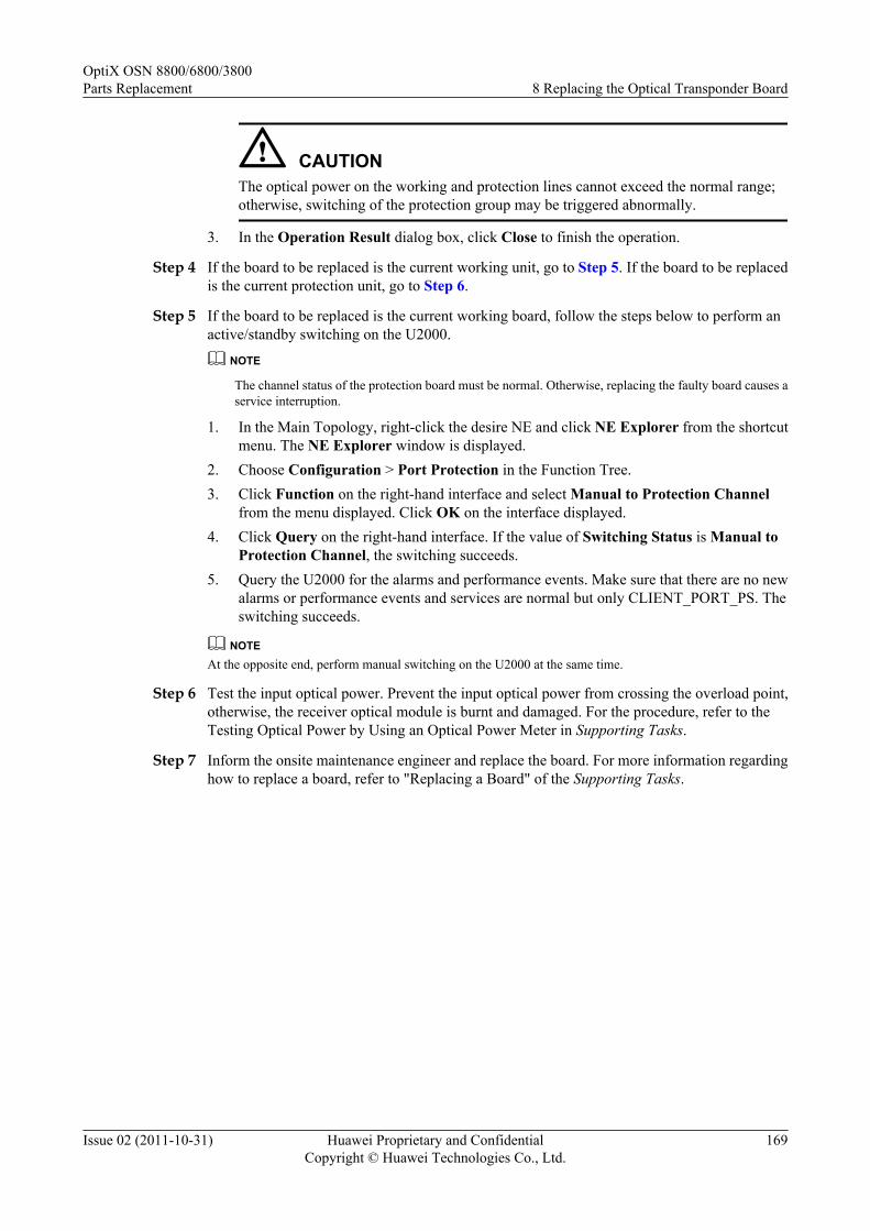
CAUTIONThe optical power on the working and protection lines cannot exceed the normal range;otherwise, switching of the protection group may be triggered abnormally.
3. In the Operation Result dialog box, click Close to finish the operation.
Step 4 If the board to be replaced is the current working unit, go to Step 5. If the board to be replacedis the current protection unit, go to Step 6.
Step 5 If the board to be replaced is the current working board, follow the steps below to perform anactive/standby switching on the U2000.
NOTE
The channel status of the protection board must be normal. Otherwise, replacing the faulty board causes aservice interruption.
1. In the Main Topology, right-click the desire NE and click NE Explorer from the shortcutmenu. The NE Explorer window is displayed.
2. Choose Configuration > Port Protection in the Function Tree.3. Click Function on the right-hand interface and select Manual to Protection Channel
from the menu displayed. Click OK on the interface displayed.4. Click Query on the right-hand interface. If the value of Switching Status is Manual to
Protection Channel, the switching succeeds.5. Query the U2000 for the alarms and performance events. Make sure that there are no new
alarms or performance events and services are normal but only CLIENT_PORT_PS. Theswitching succeeds.
NOTEAt the opposite end, perform manual switching on the U2000 at the same time.
Step 6 Test the input optical power. Prevent the input optical power from crossing the overload point,otherwise, the receiver optical module is burnt and damaged. For the procedure, refer to theTesting Optical Power by Using an Optical Power Meter in Supporting Tasks.
Step 7 Inform the onsite maintenance engineer and replace the board. For more information regardinghow to replace a board, refer to "Replacing a Board" of the Supporting Tasks.
OptiX OSN 8800/6800/3800Parts Replacement 8 Replacing the Optical Transponder Board
Issue 02 (2011-10-31) Huawei Proprietary and ConfidentialCopyright © Huawei Technologies Co., Ltd.
169

NOTE
l If the software version of the spare board is V100R004C01 or earlier, perform the following operationsbefore replacing the board:
l If the board is installed in the OptiX OSN 3800 subrack, no operation is required.
l If the OptiX OSN 8800 T64 functions as the master subrack, you need to take the following actionson the replacement board before replacing any original board on the NE. Otherwise, the services of theactive boards in other slots may be interrupted.
l a. Install the spare board to any available slot of the OptiX OSN 6800 subrack of versionV100R004C02 or later. Note that the master subrack of the NE where the OptiX OSN 6800 subrackis located cannot be OptiX OSN 8800 T64. For more information regarding the valid slots of theboard, see "Valid Slots" in the Hardware Description.
l b. When the replacement board is in service, review the indicators on the board. If any indicatorflashes abnormally, reset or replace the replacement board. For description of the indicators, see"Indicator" in the Hardware Description.
l c. Double-click the icon of the optical NE in the Physical View, and the NE Panel is displayed.Click the NE where the replacement board resides.
l d. Right-click the slot where the replacement board resides. Choose Add Physical Board from theshortcut menu.
l e. Right-click the slot where the replacement board resides. Choose Version from the shortcutmenu to query the board software version information, and record the displayed versioninformation.
l f. Right click the slot where the replacement board resides. Choose Delete from the shortcut menu.
l g. Right-click the slot where the board to be replaced or the board with the same type as the boardto be replaced resides. Choose Version from the shortcut menu. If the version is the same as thatrecorded in Step e, it indicates that the process of the replacement board is successful. Otherwise,reset or replace the replacement board, and repeat Steps a to g.
l h. Remove the replacement board, and the process of the replacement board is complete.
l i. Replace the fault board. For more information, refer to "Replacing a Board" of the SupportingTasks.
l If the OptiX OSN 8800 T64 does not function as the master subrack, and the board to be replaced isin any slot of the OptiX OSN 8800 T32 or OptiX OSN 8800 T64 subrack on the NE, you need toperform the following operations on the replacement board before replacing the original board.Otherwise, the services of the active boards in other slots may be interrupted. If the board is installedin the OptiX OSN 6800 subrack, no operation is required.
l a. Install the spare board in any available slot of the OptiX OSN 6800 subrack of versionV100R004C02 or later. For more information regarding the valid slots of the board, see "ValidSlots" in the Hardware Description.
l b. For other operations, see the previous steps b to i.
NOTE
After the board is replaced, the NE software delivers the configuration of the original board automatically.
Step 8 Review the indicators of the new board. It takes ten minutes for a new board to work normallyafter insertion. Ensure that the STAT indicator is steady green. If the indicator gives abnormalindication, you need to reinsert the board, or replace the board again. For more informationregarding indicator definitions, refer to "Indicators" of the Hardware Description.
Step 9 Review the wavelength of the new board on the U2000. Make sure the wavelength is the sameas that of the original board.
1. In the NE Explorer, select the desired board and choose Configuration > WDMInterface from the Function Tree.
2. Select By Function, and then select Band Type/Wavelength No./Wavelength(nm)/Frequency(THz) from the drop-down list.
OptiX OSN 8800/6800/3800Parts Replacement 8 Replacing the Optical Transponder Board
Issue 02 (2011-10-31) Huawei Proprietary and ConfidentialCopyright © Huawei Technologies Co., Ltd.
170

3. Click Query to view Band Type/Wavelength No./Wavelength(nm)/Frequency(THz)of each optical port.
NOTE
If the replaced board is a tunable OTU, after the board is replaced, the SCC delivers the wavelengthconfiguration of the original board automatically.
Step 10 Follow the steps below to cancel the switching.
1. In the Main Topology, right-click the desire NE and click NE Explorer from the shortcutmenu. The NE Explorer window is displayed.
2. Choose Configuration > Port Protection in the Function Tree.3. Select the switched service, and click Function on the right-hand interface. Select Clear
from the menu displayed.4. Click Query, and review Switching Status. If the value is Idle, the switching succeeds.
Step 11 Query the 15-minute BER before FEC at the receive end of the link. Make sure that the BERbefore FEC does not deteriorate greatly from the value before board replacement.
1. Choose Performance > Browse WDM Performance from the Main Menu of theU2000, and then click the Current Performance Data tab.
2. Choose the desired boards in the left pane, and click the double-right-arrow button (red).3. Choose the option from the drop-down list next to Monitored Object Filter Condition.4. In Monitor Period, select 15-Minute.5. Click Count option button. Select options under Performance Event Type, and select
Display Zero Data for the Display Options.6. Click Query to query the performance value for bit error on the NE side.7. In the Operation Result dialog box, click Close to finish the operation.8. In the Monitored Object, FEC_BEF_COR_ER represents the BER before FEC.
Step 12 Query alarms and performances of the local NE and of the opposite NE and confirm that theoriginal alarms or performances are cleared.
----End
8.2 Under SNCP ProtectionThis section describes how to replace an OTU board when SNCP protection is configured.
PrerequisiteYou must be an NMS user with "NE and network operator" authority or higher.
Impact on SystemWhen SNCP protection is configured, replacing the OTU where the sink node is located bringsa service interruption. Replacing the OTU on other nodes brings no impact on services in caseof a normal switching.
Figure 8-2, the OTU-A and OTU-B are configured with SNCP protection. The sink node is onthe OTU-A. Replacing the OUT-A brings a service interruption. Replacing the OTU-B bringsno impact on services in case of a normal switching.
OptiX OSN 8800/6800/3800Parts Replacement 8 Replacing the Optical Transponder Board
Issue 02 (2011-10-31) Huawei Proprietary and ConfidentialCopyright © Huawei Technologies Co., Ltd.
171

During board replacement, the board software takes several minutes to be synchronized. At thispoint, the PROG indicator on the board is blinking green quickly.
For details of the SNCP protection mechanism, see the Feature Description.
Figure 8-2 SNCP protection on OTU boards
OA
OA
OA
OA
FIU
FIU
OADM OADMB A
EastWest
Working wavelength Protection wavelength
Tools, Equipment and MaterialsESD bag, U2000, optical power meter
Background InformationBefore replacing an OTU board, ensure that the wavelength of the new board is consistent withthat of the original board.
The wavelength of an OTU is printed on the front panel. For details of the bar code, see theHardware Description.
Precaution
CAUTIONWhen you connect a fiber to the input optical port of an OTU board, loosely connect the fiberto prevent the input optical power from crossing the overload point; otherwise, the receiveroptical module is burnt and damaged.The overload optical power point of an APD receiver laser is only -9 dBm, which must be takenwith special caution to prevent the optical module from being burnt or damaged.
Procedure
Step 1 Select a spare board. Ensure the name, version, model number, operating wavelength, opticalmodule and software version of the new board are the same as those of the original board.
OptiX OSN 8800/6800/3800Parts Replacement 8 Replacing the Optical Transponder Board
Issue 02 (2011-10-31) Huawei Proprietary and ConfidentialCopyright © Huawei Technologies Co., Ltd.
172

NOTE
If the version is inconsistent, you need to determine if the board with different versions can be replaced.For more information regarding the replacement relation between board versions, refer to the HardwareDescription.
Query the optical module information. For more information, refer to "Querying Optical ModuleInformation" of the Supporting Tasks.
Step 2 Review and record the current alarms on the NE. For more information, refer to "Querying theCurrent Alarms" of the Supporting Tasks.
NOTE
To replace a board in an upgrade, perform this operation to determine if abnormal alarms are generated on theNE where the board to be replaced resides and the downstream NE. If there are abnormal alarms, you need tohandle these alarms before replacing the board.
Step 3 Follow the steps below to query the working state of the OTU board to be replaced.
1. In the NE Explorer, click the NE and choose Configuration > WDM ServiceManagement from the Function Tree. Click the SNCP Service Control tab.
2. Click Query to obtain the SNCP protection state of each NE.
CAUTIONBefore maintaining trails configured with protection, perform forcible switching to ensurethat services are on the stable and available trail. This is to prevent abnormal protectionswitching caused by unstable operation of the protection group in the maintenance process.After maintenance, you can cancel the forcible switching to restore the normal state of theprotection group when both the working and protection trails are normal.
3. Select the desired service and click Function on the bottom of the right-hand pane. SelectQuery Switching Status from the menu displayed. Then, you can learn the service isworking on active path or working on standby path.
4. In the Operation Result dialog box, click Close to finish the operation.
Step 4 If the service sink resides on the board to be replaced, go to Step 7. If the service sink does notreside on the board to be replaced, go to Step 5 when the board to be replaced is the currentworking board, or go to Step 7 when the board to be replaced is the current protection board.
Step 5 If the board to be replaced is the working board and the service sink does no reside on the board,follow the steps below to perform an active/standby switching on the U2000.
NOTE
The channel status of the protection board must be normal. Otherwise, replacing the faulty board causes aservice interruption.
1. In the Main Topology, right-click the desire NE and click NE Explorer from the shortcutmenu. The NE Explorer window is displayed.
2. Choose Configuration > WDM Service Management from the Function Tree.
3. Click SNCP Service Control tab.
4. Click Function on the right-hand interface and select Manual to Protection from the menudisplayed. Click OK on the interface displayed.
OptiX OSN 8800/6800/3800Parts Replacement 8 Replacing the Optical Transponder Board
Issue 02 (2011-10-31) Huawei Proprietary and ConfidentialCopyright © Huawei Technologies Co., Ltd.
173

5. Click Function on the right-hand interface and select Query Switching Status from themenu displayed. If Manual(from working to protection) switching state is displayed inthe Status field, the switching succeeds.
6. Query the U2000 for the alarms and performance events. Make sure that there are no newalarms or performance events and services are normal but only protection switching alarm.
Step 6 At the opposite end perform a manual switching on the U2000 to ensure that the working channelat the opposite end and is consistent with that at the local end. For how to perform a manualswitching, see Step 5.
Step 7 Test the input optical power. Prevent the input optical power from crossing the overload point,otherwise, the receiver optical module is burnt and damaged. For the procedure, refer to theTesting Optical Power by Using an Optical Power Meter in Supporting Tasks.
Step 8 Inform the onsite maintenance engineer and replace the board. For more information regardinghow to replace a board, refer to "Replacing a Board" of the Supporting Tasks.
NOTE
l If the software version of the spare board is V100R004C01 or earlier, perform the following operationsbefore replacing the board:
l If the board is installed in the OptiX OSN 3800 subrack, no operation is required.
l If the OptiX OSN 8800 T64 functions as the master subrack, you need to take the following actionson the replacement board before replacing any original board on the NE. Otherwise, the services of theactive boards in other slots may be interrupted.
l a. Install the spare board to any available slot of the OptiX OSN 6800 subrack of versionV100R004C02 or later. Note that the master subrack of the NE where the OptiX OSN 6800 subrackis located cannot be OptiX OSN 8800 T64. For more information regarding the valid slots of theboard, see "Valid Slots" in the Hardware Description.
l b. When the replacement board is in service, review the indicators on the board. If any indicatorflashes abnormally, reset or replace the replacement board. For description of the indicators, see"Indicator" in the Hardware Description.
l c. Double-click the icon of the optical NE in the Physical View, and the NE Panel is displayed.Click the NE where the replacement board resides.
l d. Right-click the slot where the replacement board resides. Choose Add Physical Board from theshortcut menu.
l e. Right-click the slot where the replacement board resides. Choose Version from the shortcutmenu to query the board software version information, and record the displayed versioninformation.
l f. Right click the slot where the replacement board resides. Choose Delete from the shortcut menu.
l g. Right-click the slot where the board to be replaced or the board with the same type as the boardto be replaced resides. Choose Version from the shortcut menu. If the version is the same as thatrecorded in Step e, it indicates that the process of the replacement board is successful. Otherwise,reset or replace the replacement board, and repeat Steps a to g.
l h. Remove the replacement board, and the process of the replacement board is complete.
l i. Replace the fault board. For more information, refer to "Replacing a Board" of the SupportingTasks.
l If the OptiX OSN 8800 T64 does not function as the master subrack, and the board to be replaced isin any slot of the OptiX OSN 8800 T32 or OptiX OSN 8800 T64 subrack on the NE, you need toperform the following operations on the replacement board before replacing the original board.Otherwise, the services of the active boards in other slots may be interrupted. If the board is installedin the OptiX OSN 6800 subrack, no operation is required.
l a. Install the spare board in any available slot of the OptiX OSN 6800 subrack of versionV100R004C02 or later. For more information regarding the valid slots of the board, see "ValidSlots" in the Hardware Description.
l b. For other operations, see the previous steps b to i.
OptiX OSN 8800/6800/3800Parts Replacement 8 Replacing the Optical Transponder Board
Issue 02 (2011-10-31) Huawei Proprietary and ConfidentialCopyright © Huawei Technologies Co., Ltd.
174

NOTE
After the board is replaced, the NE software delivers the configuration of the original board automatically.
Step 9 Review the indicators of the new board. It takes ten minutes for a new board to work normallyafter insertion. Ensure that the STAT indicator is steady green. If the indicator gives abnormalindication, you need to reinsert the board, or replace the board again. For more informationregarding indicator definitions, refer to "Indicators" of the Hardware Description.
Step 10 Review the wavelength of the new board on the U2000. Make sure the wavelength is the sameas that of the original board.
1. In the NE Explorer, select the desired board and choose Configuration > WDMInterface from the Function Tree.
2. Select By Function, and then select Band Type/Wavelength No./Wavelength(nm)/Frequency(THz) from the drop-down list.
3. Click Query to view Band Type/Wavelength No./Wavelength(nm)/Frequency(THz)of each optical port.
NOTE
If the replaced board is a tunable OTU, after the board is replaced, the SCC delivers the wavelengthconfiguration of the original board automatically.
Step 11 Follow the steps below to cancel the switching.
1. In the Main Topology, right-click the desire NE and click NE Explorer from the shortcutmenu. The NE Explorer window is displayed.
2. Choose Configuration > WDM Service Management in the Function Tree.
3. Click SNCP Service Control tab.
4. Select the switched service, and click Function on the right-hand interface. Select Clearfrom the menu displayed.
5. Click Query, and review Status. If the value is Normal State, the switching succeeds.
Step 12 Query the 15-minute BER before FEC at the receive end of the link. Make sure that the BERbefore FEC does not deteriorate greatly from the value before board replacement.
1. Choose Performance > Browse WDM Performance from the Main Menu of theU2000, and then click the Current Performance Data tab.
2. Choose the desired boards in the left pane, and click the double-right-arrow button (red).
3. Choose the option from the drop-down list next to Monitored Object Filter Condition.
4. In Monitor Period, select 15-Minute.
5. Click Count option button. Select options under Performance Event Type, and selectDisplay Zero Data for the Display Options.
6. Click Query to query the performance value for bit error on the NE side.
7. In the Operation Result dialog box, click Close to finish the operation.
8. In the Monitored Object, FEC_BEF_COR_ER represents the BER before FEC.
Step 13 Query alarms and performances of the local NE and of the opposite NE and confirm that theoriginal alarms or performances are cleared.
----End
OptiX OSN 8800/6800/3800Parts Replacement 8 Replacing the Optical Transponder Board
Issue 02 (2011-10-31) Huawei Proprietary and ConfidentialCopyright © Huawei Technologies Co., Ltd.
175

8.3 Under OWSP ProtectionThis section describes how to replace an OTU board when OWSP protection is configured.
PrerequisiteYou must be an NMS user with "NE and network operator" authority or higher.
Impact on System
When OWSP protection is configured, replacing an OTU board brings a service interruption onthe OTU.
In Figure 8-3, the OTU1 and the OTU2 are configured with OWSP protection. Replacing theOTU1 or OTU2 brings a service interruption.
During board replacement, the board software takes several minutes to be synchronized. At thispoint, the PROG indicator on the board is blinking green quickly.
For details of the OWSP protection mechanism, see the Feature Description.
Figure 8-3 OWSP protection on OTU boards
OTU2 OTU1 OTU2 OTU1
2 x DCP
OTU1 OTU2 OTU1 OTU2
OADM(East)
FIU
FIU
OADM
FIU OADMFIU
OADM
FIU
FIU
OADM
OADM FIU OADMFIU
λ2/λ1 λ1/λ2
λ2/λ1
λ2λ1
1λ 2
λ2λ1
λ1λ2
λ2/λ1
λ2/λ1 λ2λ1
λ2λ1
A
B C
D
λ1/λ2
λ1/λ2 λ2/λ1
λ2/λ1
2 x DCP
2 x DCP2 x DCPλ2/λ1
λ1/λ2
λ1/λ2
λ1/λ2
λ1/λ2λ2/λ1
λ1/λ2 λ1λ 2
λ1λ 2
(East)
(East)
(West)
Working wavelength Protection wavelength
OADM(West)
λ
(West)
(West) (East)
OptiX OSN 8800/6800/3800Parts Replacement 8 Replacing the Optical Transponder Board
Issue 02 (2011-10-31) Huawei Proprietary and ConfidentialCopyright © Huawei Technologies Co., Ltd.
176

Tools, Equipment and Materials
ESD bag, U2000, optical power meter
Background Information
Before replacing an OTU board, ensure that the wavelength of the new board is consistent withthat of the original board.
The wavelength of an OTU is printed on the front panel. For details of the bar code, see theHardware Description.
Precaution
CAUTIONWhen you connect a fiber to the input optical port of an OTU board, loosely connect the fiberto prevent the input optical power from crossing the overload point; otherwise, the receiveroptical module is burnt and damaged.
The overload optical power point of an APD receiver laser is only -9 dBm, which must be takenwith special caution to prevent the optical module from being burnt or damaged.
Procedure
Step 1 Select a spare board. Ensure the name, version, model number, operating wavelength, opticalmodule and software version of the new board are the same as those of the original board.
NOTE
If the version is inconsistent, you need to determine if the board with different versions can be replaced.For more information regarding the replacement relation between board versions, refer to the HardwareDescription.
Query the optical module information. For more information, refer to "Querying Optical ModuleInformation" of the Supporting Tasks.
Step 2 Review and record the current alarms on the NE. For more information, refer to "Querying theCurrent Alarms" of the Supporting Tasks.
NOTE
To replace a board in an upgrade, perform this operation to determine if abnormal alarms are generated on theNE where the board to be replaced resides and the downstream NE. If there are abnormal alarms, you need tohandle these alarms before replacing the board.
Step 3 Test the input optical power. Prevent the input optical power from crossing the overload point,otherwise, the receiver optical module is burnt and damaged. For the procedure, refer to theTesting Optical Power by Using an Optical Power Meter in Supporting Tasks.
Step 4 Inform the onsite maintenance engineer and replace the board. For more information regardinghow to replace a board, refer to "Replacing a Board" of the Supporting Tasks.
OptiX OSN 8800/6800/3800Parts Replacement 8 Replacing the Optical Transponder Board
Issue 02 (2011-10-31) Huawei Proprietary and ConfidentialCopyright © Huawei Technologies Co., Ltd.
177
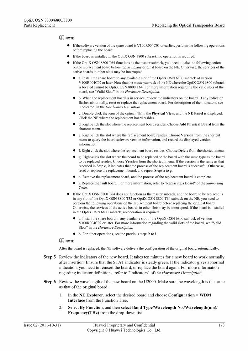
NOTE
l If the software version of the spare board is V100R004C01 or earlier, perform the following operationsbefore replacing the board:
l If the board is installed in the OptiX OSN 3800 subrack, no operation is required.
l If the OptiX OSN 8800 T64 functions as the master subrack, you need to take the following actionson the replacement board before replacing any original board on the NE. Otherwise, the services of theactive boards in other slots may be interrupted.
l a. Install the spare board to any available slot of the OptiX OSN 6800 subrack of versionV100R004C02 or later. Note that the master subrack of the NE where the OptiX OSN 6800 subrackis located cannot be OptiX OSN 8800 T64. For more information regarding the valid slots of theboard, see "Valid Slots" in the Hardware Description.
l b. When the replacement board is in service, review the indicators on the board. If any indicatorflashes abnormally, reset or replace the replacement board. For description of the indicators, see"Indicator" in the Hardware Description.
l c. Double-click the icon of the optical NE in the Physical View, and the NE Panel is displayed.Click the NE where the replacement board resides.
l d. Right-click the slot where the replacement board resides. Choose Add Physical Board from theshortcut menu.
l e. Right-click the slot where the replacement board resides. Choose Version from the shortcutmenu to query the board software version information, and record the displayed versioninformation.
l f. Right click the slot where the replacement board resides. Choose Delete from the shortcut menu.
l g. Right-click the slot where the board to be replaced or the board with the same type as the boardto be replaced resides. Choose Version from the shortcut menu. If the version is the same as thatrecorded in Step e, it indicates that the process of the replacement board is successful. Otherwise,reset or replace the replacement board, and repeat Steps a to g.
l h. Remove the replacement board, and the process of the replacement board is complete.
l i. Replace the fault board. For more information, refer to "Replacing a Board" of the SupportingTasks.
l If the OptiX OSN 8800 T64 does not function as the master subrack, and the board to be replaced isin any slot of the OptiX OSN 8800 T32 or OptiX OSN 8800 T64 subrack on the NE, you need toperform the following operations on the replacement board before replacing the original board.Otherwise, the services of the active boards in other slots may be interrupted. If the board is installedin the OptiX OSN 6800 subrack, no operation is required.
l a. Install the spare board in any available slot of the OptiX OSN 6800 subrack of versionV100R004C02 or later. For more information regarding the valid slots of the board, see "ValidSlots" in the Hardware Description.
l b. For other operations, see the previous steps b to i.
NOTE
After the board is replaced, the NE software delivers the configuration of the original board automatically.
Step 5 Review the indicators of the new board. It takes ten minutes for a new board to work normallyafter insertion. Ensure that the STAT indicator is steady green. If the indicator gives abnormalindication, you need to reinsert the board, or replace the board again. For more informationregarding indicator definitions, refer to "Indicators" of the Hardware Description.
Step 6 Review the wavelength of the new board on the U2000. Make sure the wavelength is the sameas that of the original board.
1. In the NE Explorer, select the desired board and choose Configuration > WDMInterface from the Function Tree.
2. Select By Function, and then select Band Type/Wavelength No./Wavelength(nm)/Frequency(THz) from the drop-down list.
OptiX OSN 8800/6800/3800Parts Replacement 8 Replacing the Optical Transponder Board
Issue 02 (2011-10-31) Huawei Proprietary and ConfidentialCopyright © Huawei Technologies Co., Ltd.
178

3. Click Query to view Band Type/Wavelength No./Wavelength(nm)/Frequency(THz)of each optical port.
NOTE
If the replaced board is a tunable OTU, after the board is replaced, the SCC delivers the wavelengthconfiguration of the original board automatically.
Step 7 Query the 15-minute BER before FEC at the receive end of the link. Make sure that the BERbefore FEC does not deteriorate greatly from the value before board replacement.
1. Choose Performance > Browse WDM Performance from the Main Menu of theU2000, and then click the Current Performance Data tab.
2. Choose the desired boards in the left pane, and click the double-right-arrow button (red).3. Choose the option from the drop-down list next to Monitored Object Filter Condition.4. In Monitor Period, select 15-Minute.5. Click Count option button. Select options under Performance Event Type, and select
Display Zero Data for the Display Options.6. Click Query to query the performance value for bit error on the NE side.7. In the Operation Result dialog box, click Close to finish the operation.8. In the Monitored Object, FEC_BEF_COR_ER represents the BER before FEC.
Step 8 Query alarms and performances of the local NE and of the opposite NE and confirm that theoriginal alarms or performances are cleared.
----End
8.4 Under No ProtectionThis section describes how to replace an OTU board when no protection is configured.
PrerequisiteYou must be an NMS user with "NE and network operator" authority or higher.
Impact on SystemReplacing unprotected OTU boards brings a service interruption.
During board replacement, the board software takes several minutes to be synchronized. At thispoint, the PROG indicator on the board is blinking green quickly.
Tools, Equipment, and MaterialsESD bag, U2000, optical power meter
Background InformationBefore replacing an OTU board, ensure that the wavelength of the new board is consistent withthat of the original board.
The wavelength of an OTU is printed on the front panel. For details about the bar code, see theHardware Description.
OptiX OSN 8800/6800/3800Parts Replacement 8 Replacing the Optical Transponder Board
Issue 02 (2011-10-31) Huawei Proprietary and ConfidentialCopyright © Huawei Technologies Co., Ltd.
179
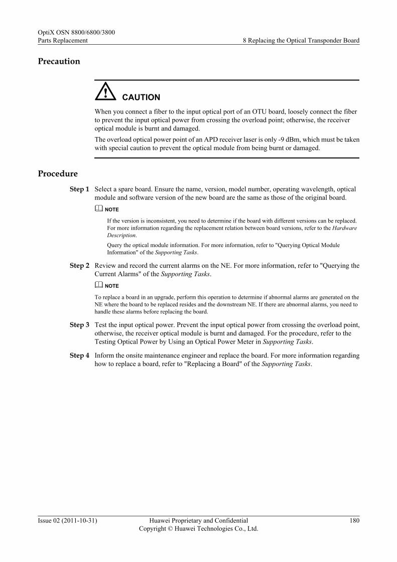
Precaution
CAUTIONWhen you connect a fiber to the input optical port of an OTU board, loosely connect the fiberto prevent the input optical power from crossing the overload point; otherwise, the receiveroptical module is burnt and damaged.The overload optical power point of an APD receiver laser is only -9 dBm, which must be takenwith special caution to prevent the optical module from being burnt or damaged.
Procedure
Step 1 Select a spare board. Ensure the name, version, model number, operating wavelength, opticalmodule and software version of the new board are the same as those of the original board.
NOTE
If the version is inconsistent, you need to determine if the board with different versions can be replaced.For more information regarding the replacement relation between board versions, refer to the HardwareDescription.
Query the optical module information. For more information, refer to "Querying Optical ModuleInformation" of the Supporting Tasks.
Step 2 Review and record the current alarms on the NE. For more information, refer to "Querying theCurrent Alarms" of the Supporting Tasks.
NOTE
To replace a board in an upgrade, perform this operation to determine if abnormal alarms are generated on theNE where the board to be replaced resides and the downstream NE. If there are abnormal alarms, you need tohandle these alarms before replacing the board.
Step 3 Test the input optical power. Prevent the input optical power from crossing the overload point,otherwise, the receiver optical module is burnt and damaged. For the procedure, refer to theTesting Optical Power by Using an Optical Power Meter in Supporting Tasks.
Step 4 Inform the onsite maintenance engineer and replace the board. For more information regardinghow to replace a board, refer to "Replacing a Board" of the Supporting Tasks.
OptiX OSN 8800/6800/3800Parts Replacement 8 Replacing the Optical Transponder Board
Issue 02 (2011-10-31) Huawei Proprietary and ConfidentialCopyright © Huawei Technologies Co., Ltd.
180

NOTE
l If the software version of the spare board is V100R004C01 or earlier, perform the following operationsbefore replacing the board:
l If the board is installed in the OptiX OSN 3800 subrack, no operation is required.
l If the OptiX OSN 8800 T64 functions as the master subrack, you need to take the following actionson the replacement board before replacing any original board on the NE. Otherwise, the services of theactive boards in other slots may be interrupted.
l a. Install the spare board to any available slot of the OptiX OSN 6800 subrack of versionV100R004C02 or later. Note that the master subrack of the NE where the OptiX OSN 6800 subrackis located cannot be OptiX OSN 8800 T64. For more information regarding the valid slots of theboard, see "Valid Slots" in the Hardware Description.
l b. When the replacement board is in service, review the indicators on the board. If any indicatorflashes abnormally, reset or replace the replacement board. For description of the indicators, see"Indicator" in the Hardware Description.
l c. Double-click the icon of the optical NE in the Physical View, and the NE Panel is displayed.Click the NE where the replacement board resides.
l d. Right-click the slot where the replacement board resides. Choose Add Physical Board from theshortcut menu.
l e. Right-click the slot where the replacement board resides. Choose Version from the shortcutmenu to query the board software version information, and record the displayed versioninformation.
l f. Right click the slot where the replacement board resides. Choose Delete from the shortcut menu.
l g. Right-click the slot where the board to be replaced or the board with the same type as the boardto be replaced resides. Choose Version from the shortcut menu. If the version is the same as thatrecorded in Step e, it indicates that the process of the replacement board is successful. Otherwise,reset or replace the replacement board, and repeat Steps a to g.
l h. Remove the replacement board, and the process of the replacement board is complete.
l i. Replace the fault board. For more information, refer to "Replacing a Board" of the SupportingTasks.
l If the OptiX OSN 8800 T64 does not function as the master subrack, and the board to be replaced isin any slot of the OptiX OSN 8800 T32 or OptiX OSN 8800 T64 subrack on the NE, you need toperform the following operations on the replacement board before replacing the original board.Otherwise, the services of the active boards in other slots may be interrupted. If the board is installedin the OptiX OSN 6800 subrack, no operation is required.
l a. Install the spare board in any available slot of the OptiX OSN 6800 subrack of versionV100R004C02 or later. For more information regarding the valid slots of the board, see "ValidSlots" in the Hardware Description.
l b. For other operations, see the previous steps b to i.
NOTE
After the board is replaced, the NE software delivers the configuration of the original board automatically.
Step 5 Review the indicators of the new board. It takes ten minutes for a new board to work normallyafter insertion. Ensure that the STAT indicator is steady green. If the indicator gives abnormalindication, you need to reinsert the board, or replace the board again. For more informationregarding indicator definitions, refer to "Indicators" of the Hardware Description.
Step 6 Review the wavelength of the new board on the U2000. Make sure the wavelength is the sameas that of the original board.
1. In the NE Explorer, select the desired board and choose Configuration > WDMInterface from the Function Tree.
2. Select By Function, and then select Band Type/Wavelength No./Wavelength(nm)/Frequency(THz) from the drop-down list.
OptiX OSN 8800/6800/3800Parts Replacement 8 Replacing the Optical Transponder Board
Issue 02 (2011-10-31) Huawei Proprietary and ConfidentialCopyright © Huawei Technologies Co., Ltd.
181

3. Click Query to view Band Type/Wavelength No./Wavelength(nm)/Frequency(THz)of each optical port.
NOTE
If the replaced board is a tunable OTU, after the board is replaced, the SCC delivers the wavelengthconfiguration of the original board automatically.
Step 7 Query the 15-minute BER before FEC at the receive end of the link. Make sure that the BERbefore FEC does not deteriorate greatly from the value before board replacement.
1. Choose Performance > Browse WDM Performance from the Main Menu of theU2000, and then click the Current Performance Data tab.
2. Choose the desired boards in the left pane, and click the double-right-arrow button (red).3. Choose the option from the drop-down list next to Monitored Object Filter Condition.4. In Monitor Period, select 15-Minute.5. Click Count option button. Select options under Performance Event Type, and select
Display Zero Data for the Display Options.6. Click Query to query the performance value for bit error on the NE side.7. In the Operation Result dialog box, click Close to finish the operation.8. In the Monitored Object, FEC_BEF_COR_ER represents the BER before FEC.
Step 8 Query alarms and performances of the local NE and of the opposite NE and confirm that theoriginal alarms or performances are cleared.
----End
OptiX OSN 8800/6800/3800Parts Replacement 8 Replacing the Optical Transponder Board
Issue 02 (2011-10-31) Huawei Proprietary and ConfidentialCopyright © Huawei Technologies Co., Ltd.
182
9 Replacing the Tributary and Line Board
About This Chapter
This section describes how to replace the tributary and line board.
For OptiX OSN 8800, a tributary or line board can be replaced when:
l The client 1+1 protection is provided.l SNCP protection is provided.l ODUk SPRing Protection is providedl No protection is provided.
For OptiX OSN 6800/3800, a tributary or line board can be replaced when:
l The client 1+1 protection is provided.l SNCP protection is provided.l ODUk SPRing Protection is providedl DBPS Protection is providedl DLAG Protection is providedl Board-level Protection is providedl No protection is provided.
9.1 Under Client 1+1 ProtectionThis section describes how to replace a line board or a tributary board when client 1+1 protectionis configured.
9.2 Under SNCP ProtectionThis section describes how to replace a line board or a tributary board when SNCP protectionis configured.
9.3 Under ODUk SPRing ProtectionThis section describes how to replace a line board or a tributary board when ODUk SPRingprotection is configured.
9.4 Under DBPS ProtectionThis section describes how to replace the TBE board when no DBPS protection is configured.
9.5 Under DLAG Protection
OptiX OSN 8800/6800/3800Parts Replacement 9 Replacing the Tributary and Line Board
Issue 02 (2011-10-31) Huawei Proprietary and ConfidentialCopyright © Huawei Technologies Co., Ltd.
183

This section describes how to replace the TBE board when DLAG protection is configured.
9.6 Under Board-Level ProtectionThis section describes how to replace a TBE board when board-level protection is configured.
9.7 Under No ProtectionThis section describes how to replace a line board or a tributary board when no protection isconfigured.
OptiX OSN 8800/6800/3800Parts Replacement 9 Replacing the Tributary and Line Board
Issue 02 (2011-10-31) Huawei Proprietary and ConfidentialCopyright © Huawei Technologies Co., Ltd.
184
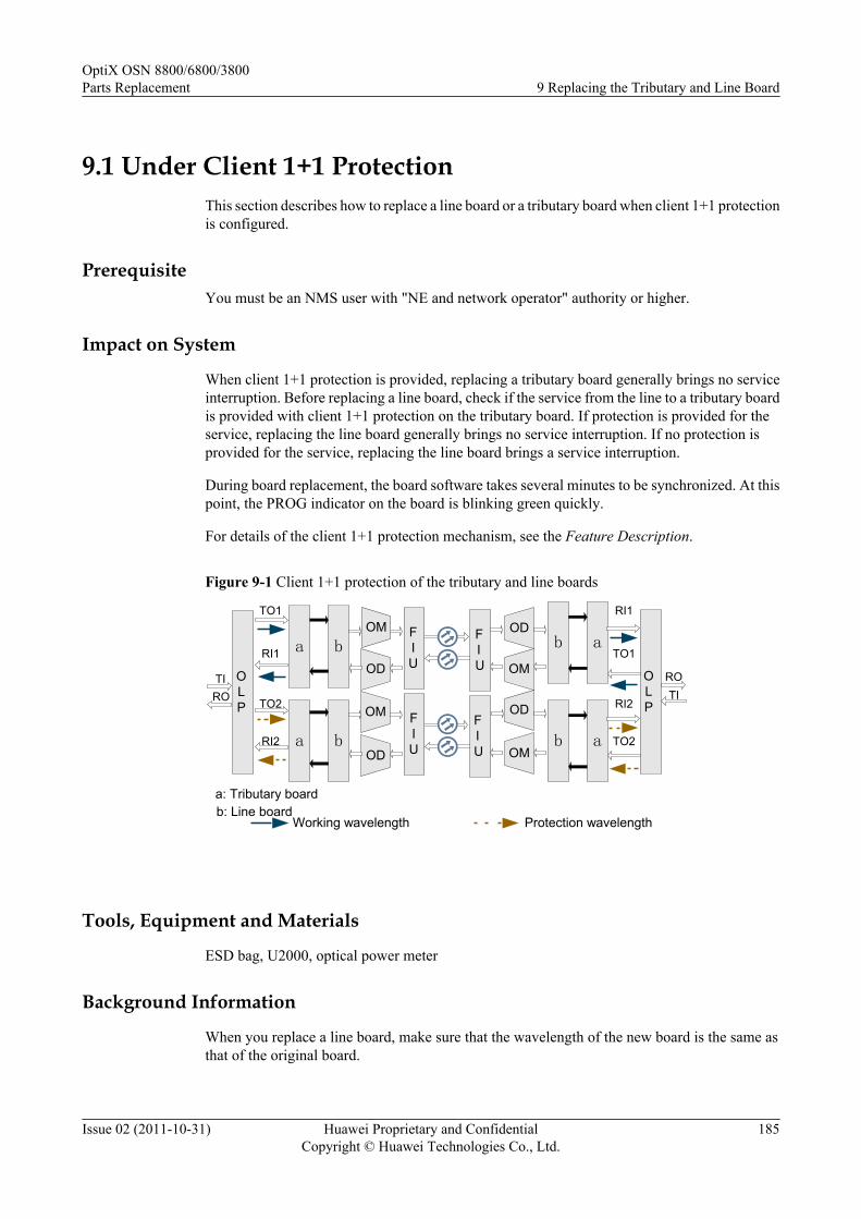
9.1 Under Client 1+1 ProtectionThis section describes how to replace a line board or a tributary board when client 1+1 protectionis configured.
PrerequisiteYou must be an NMS user with "NE and network operator" authority or higher.
Impact on System
When client 1+1 protection is provided, replacing a tributary board generally brings no serviceinterruption. Before replacing a line board, check if the service from the line to a tributary boardis provided with client 1+1 protection on the tributary board. If protection is provided for theservice, replacing the line board generally brings no service interruption. If no protection isprovided for the service, replacing the line board brings a service interruption.
During board replacement, the board software takes several minutes to be synchronized. At thispoint, the PROG indicator on the board is blinking green quickly.
For details of the client 1+1 protection mechanism, see the Feature Description.
Figure 9-1 Client 1+1 protection of the tributary and line boards
OM
OD
OD
OM OD
OM
OD
OM
FIU
FIU
FIU
OLP
TIRO
ROTI
OLP
FIU
Working wavelength Protection wavelength
a: Tributary boardb: Line board
a b b a
b aa b
TO1
RI1
TO2
RI2
TO1
RI1
TO2
RI2
Tools, Equipment and Materials
ESD bag, U2000, optical power meter
Background Information
When you replace a line board, make sure that the wavelength of the new board is the same asthat of the original board.
OptiX OSN 8800/6800/3800Parts Replacement 9 Replacing the Tributary and Line Board
Issue 02 (2011-10-31) Huawei Proprietary and ConfidentialCopyright © Huawei Technologies Co., Ltd.
185
Precaution
CAUTIONWhen you connect a fiber to the input optical port of a line board or tributary board, looselyconnect the fiber to prevent the input optical power from crossing the overload point; otherwise,the receiver optical module is burnt and damaged.The overload optical power point of an APD receiver laser is only -9 dBm, which must be takenwith special caution to prevent the optical module from being burnt or damaged.
Procedurel Procedure for Replacing a Line Board.
1. Select a spare board. The name, version, model number, operating wavelength, opticalmodule and software version of the new board must be the same as those of the originalboard.
NOTE
If the version is inconsistent, you need to check whether the board with different versions canbe replaced. For details about the replacement relationship between board versions, see theHardware Description.
Query the optical module information. For details, see "Querying Optical Module Information"of the Supporting Tasks.
2. Query and record the current alarms on the NE. For details, see "Querying the CurrentAlarms" of the Supporting Tasks.
NOTE
When a line or tributary board needs to be replaced for the upgrade purpose, perform this step tocheck whether abnormal alarms are generated on the NE where the board is located and thedownstream NE. If abnormal alarms are generated, remove these alarms before you replace theboard.
3. Test the input optical power. Prevent the input optical power from crossing theoverload point; otherwise, the receiver optical module is burnt and damaged. For theprocedure, see the "Testing Optical Power by Using an Optical Power Meter" inSupporting Tasks.
4. Follow the steps below to check on which tributary board or OTU the services withelectrical cross-connections on the line board resides.
(1) Double click the ONE icon on the Physical View and the NE Panel tab isdisplayed.
(2) Right-click the NE icon and select NE Explorer.(3) Choose Configuration > WDM Service Management from the Function Tree.
Click Query to query all electrical cross-connection services.(4) Search all services with the source path on the line board to be replaced. Record
the tributary or OTU boards where the sink paths of the services are located.5. Follow the steps below to query the working state of the tributary board or OTU.
(1) In the NE Explorer, click the NE and choose Configuration > PortProtection from the Function Tree. All port protection pairs are listed, you candistinguish the protection by Protection Type.
OptiX OSN 8800/6800/3800Parts Replacement 9 Replacing the Tributary and Line Board
Issue 02 (2011-10-31) Huawei Proprietary and ConfidentialCopyright © Huawei Technologies Co., Ltd.
186

(2) Click Query to query the switching state of each protection group and the stateof working channel and protection channel.
TIPYou can also choose Inventory > WDM Statistic Report > WDM Protection GroupSwitching State Report from the main menu of U2000 to query the optical lineprotection switching state in the WDM Protection Group Switching State Reportwindow.
CAUTIONBefore maintaining trails configured with protection, perform forcible switchingto ensure that services are on the stable and available trail. This is to preventabnormal protection switching caused by unstable operation of the protectiongroup in the maintenance process. After maintenance, you can cancel the forcibleswitching to restore the normal state of the protection group when both theworking and protection trails are normal.
CAUTIONThe optical power on the working and protection lines cannot exceed the normalrange; otherwise, switching of the protection group may be triggered abnormally.
(3) In the Operation Result dialog box, click Close to finish the operation.6. If the tributary board or OTU corresponding to the line board to be replaced is the
working unit, go to Step 7. If the tributary board corresponding to the line board tobe replaced is the protection unit, go to Step 8.
7. If the tributary board or OTU is the current working board, follow the steps below toperform an active/standby switching on the U2000.
NOTE
The channel status of the protection board to which the service is to be switched must be normal.Otherwise, replacing the faulty board causes a service interruption.
(1) In the Main Topology, right-click the desire NE and click NE Explorer from theshortcut menu. The NE Explorer window is displayed.
(2) Choose Configuration > Port Protection in the Function Tree.(3) Click Function on the right-hand interface and select Manual to Protection
Channel from the menu displayed. Click OK on the interface displayed.(4) Click Query on the right-hand interface. If the value of Switching Status is
Manual to Protection Channel, the switching succeeds.(5) Query the U2000 for the alarms and performance events. Make sure that there
are no new alarms or performance events and services are normal but onlyCLIENT_PORT_PS. The switching succeeds.
8. Inform the onsite maintenance engineer and replace the board. For details on how toreplace a board, see "Replacing a Board" of the Supporting Tasks.
OptiX OSN 8800/6800/3800Parts Replacement 9 Replacing the Tributary and Line Board
Issue 02 (2011-10-31) Huawei Proprietary and ConfidentialCopyright © Huawei Technologies Co., Ltd.
187
NOTE
l If the software version of the spare board is V100R004C01 or earlier, perform the followingoperations before replacing the board:
l If the board is installed in the OptiX OSN 3800 subrack, no operation is required.
l If the OptiX OSN 8800 T64 functions as the master subrack, you need to take the followingactions on the replacement board before replacing any original board on the NE. Otherwise,the services of the active boards in other slots may be interrupted.
l a. Install the spare board to any available slot of the OptiX OSN 6800 subrack of versionV100R004C02 or later. Note that the master subrack of the NE where the OptiX OSN6800 subrack is located cannot be OptiX OSN 8800 T64. For details of the valid slotsof the board, see "Valid Slots" in the Hardware Description.
l b. When the replacement board is in service, check the indicators on the board. If anyindicator blinks abnormally, reset or replace the replacement board. For description ofthe indicators, see "Indicator" in the Hardware Description.
l c. Double-click the icon of the optical NE in the Physical View, and the NE Panel isdisplayed. Click the NE where the replacement board resides.
l d. Right-click the slot where the replacement board resides. Choose Add PhysicalBoard from the shortcut menu.
l e. Right-click the slot where the replacement board resides. Choose Version from theshortcut menu to query the board software version information, and record thedisplayed version information.
l f. Right click the slot where the replacement board resides. Choose Delete from theshortcut menu.
l g. Right-click the slot where the board to be replaced or the board with the same typeas the board to be replaced resides. Choose Version from the shortcut menu. If theversion is the same as that recorded in Step e, it indicates that the process of thereplacement board is successful. Otherwise, reset or replace the replacement board, andrepeat Steps a to g.
l h. Remove the replacement board, and the process of the replacement board is complete.
l i. Replace the fault board, for details, see "Replacing a Board" of the SupportingTasks.
l If the OptiX OSN 8800 T64 does not function as the master subrack, and the board to bereplaced is in any slot of the OptiX OSN 8800 T32 or OptiX OSN 8800 T64 subrack onthe NE, you need to perform the following operations on the replacement board beforereplacing the original board. Otherwise, the services of the active boards in other slots maybe interrupted. If the board is installed in the OptiX OSN 6800 subrack, no operation isrequired.
l a. Install the spare board in any available slot of the OptiX OSN 6800 subrack of versionV100R004C02 or later. For details of the valid slots of the board, see "Valid Slots" inthe Hardware Description.
l b. For other operations, see the previous steps b to i.
NOTE
After the board is replaced, the NE software delivers the configuration of the original boardautomatically.
9. View the indicators on the front panel of the new board. It takes approximately threeor four minutes for a new board to work normally after insertion. Ensure that the STATindicator is steady on green. If the indicator is not steady on green, you need to reinsertthe board or select a new replacement board. For details about the indicators, see"Indicators" of the Hardware Description.
10. When you replace a line board, check on the U2000 the wavelength of the new board.Make sure the wavelength is the same as that of the original board.
OptiX OSN 8800/6800/3800Parts Replacement 9 Replacing the Tributary and Line Board
Issue 02 (2011-10-31) Huawei Proprietary and ConfidentialCopyright © Huawei Technologies Co., Ltd.
188

(1) In the NE Explorer, select the desired board and choose Configuration > WDMInterface from the Function Tree.
(2) Select By Function, and then select Band Type/Wavelength No./Wavelength(nm)/Frequency(THz) from the drop-down list.
(3) Click Query to view Band Type/Wavelength No./Wavelength(nm)/Frequency(THz) of each optical port.
NOTE
If the replaced board is a tunable line board, after the board is replaced, the SCC delivers thewavelength configuration of the original board automatically.
11. Follow the steps below to cancel the switching.
(1) In the Main Topology, right-click the desire NE and click NE Explorer from theshortcut menu. The NE Explorer window is displayed.
(2) Choose Configuration > Port Protection in the Function Tree.(3) Select the switched service, and click Function on the right-hand interface.
Select Clear from the menu displayed.(4) Click Query, and review Switching Status. If the value is Idle, the switching
succeeds.12. At the receive end of the link, query the 15-minute BER before correction to ensure
that this data does not deteriorate after the board is replaced.
(1) Choose Performance > Browse WDM Performance from the Main Menu ofthe U2000, and then click the Current Performance Data tab.
(2) Choose the desired boards in the left pane, and click the double-right-arrowbutton (red).
(3) Choose the option from the drop-down list next to Monitored Object FilterCondition.
(4) In Monitor Period, select 15-Minute.(5) Click Count option button. Select options under Performance Event Type, and
select Display Zero Data for the Display Options.(6) Click Query to query the performance value for bit error on the NE side.(7) In the Operation Result dialog box, click Close to finish the operation.(8) In the Monitored Object, FEC_BEF_COR_ER represents the BER before
FEC.13. Query board alarms of the local NE and of the opposite NE and confirm that the
original alarms or performances are cleared.
(1) In the Main Topology view, choose Fault > Browse Current Alarm from theMain Menu.
(2) Click the Basic Setting and Alarm Source tabs in turn on the Filter dialog boxto set the filter conditions for the current alarms.
(3) Click OK.(4) Record the current alarms of the NE.
NOTEYou can select the desired alarms and right-click to choose Save > Save SelectedRecords, or right-click to choose Save > Save All Records from the shortcut menu tosave the current alarms of the NE.
l Procedure for Replacing a Tributary Board.
OptiX OSN 8800/6800/3800Parts Replacement 9 Replacing the Tributary and Line Board
Issue 02 (2011-10-31) Huawei Proprietary and ConfidentialCopyright © Huawei Technologies Co., Ltd.
189

1. Select a spare board. The name, version, model number, optical module and softwareversion of the new board must be the same as those of the original board.
NOTE
If the version is inconsistent, you need to check whether the board with different versions canbe replaced. For details about the replacement relationship between board versions, see theHardware Description.
Query the optical module information. For details, see "Querying Optical Module Information"of the Supporting Tasks.
2. Query and record the current alarms on the NE. For details, see "Querying the CurrentAlarms" of the Supporting Tasks.
NOTE
When a line or tributary board needs to be replaced for the upgrade purpose, perform this step tocheck whether abnormal alarms are generated on the NE where the board is located and thedownstream NE. If abnormal alarms are generated, remove these alarms before you replace theboard.
3. Follow the steps below to query the working state of the board to be replaced:
(1) In the NE Explorer, click the NE and choose Configuration > PortProtection from the Function Tree. All port protection pairs are listed, you candistinguish the protection by Protection Type.
(2) Click Query to query the switching state of each protection group and the stateof working channel and protection channel.
TIPYou can also choose Inventory > WDM Statistic Report > WDM Protection GroupSwitching State Report from the main menu of U2000 to query the optical lineprotection switching state in the WDM Protection Group Switching State Reportwindow.
CAUTIONBefore maintaining trails configured with protection, perform forcible switchingto ensure that services are on the stable and available trail. This is to preventabnormal protection switching caused by unstable operation of the protectiongroup in the maintenance process. After maintenance, you can cancel the forcibleswitching to restore the normal state of the protection group when both theworking and protection trails are normal.
CAUTIONThe optical power on the working and protection lines cannot exceed the normalrange; otherwise, switching of the protection group may be triggered abnormally.
(3) In the Operation Result dialog box, click Close to finish the operation.
4. If the board to be replaced is the current working unit, go to Step 5. If the board to bereplaced is the current protection unit, go to Step 6.
5. If the board to be replaced is the current working board, follow the steps below toperform an active/standby switching on the U2000.
OptiX OSN 8800/6800/3800Parts Replacement 9 Replacing the Tributary and Line Board
Issue 02 (2011-10-31) Huawei Proprietary and ConfidentialCopyright © Huawei Technologies Co., Ltd.
190
(1) In the Main Topology, right-click the desire NE and click NE Explorer from theshortcut menu. The NE Explorer window is displayed.
(2) Choose Configuration > Port Protection in the Function Tree.(3) Click Function on the right-hand interface and select Manual to Protection
Channel from the menu displayed. Click OK on the interface displayed.(4) Click Query on the right-hand interface. If the value of Switching Status is
Manual to Protection Channel, the switching succeeds.(5) Query the U2000 for the alarms and performance events. Make sure that there
are no new alarms or performance events and services are normal but onlyCLIENT_PORT_PS. The switching succeeds.
6. Inform the onsite maintenance engineer and replace the board. For details on how toreplace a board, see "Replacing a Board" of the Supporting Tasks.
OptiX OSN 8800/6800/3800Parts Replacement 9 Replacing the Tributary and Line Board
Issue 02 (2011-10-31) Huawei Proprietary and ConfidentialCopyright © Huawei Technologies Co., Ltd.
191

NOTE
l If the software version of the spare board is V100R004C01 or earlier, perform the followingoperations before replacing the board:
l If the board is installed in the OptiX OSN 3800 subrack, no operation is required.
l If the OptiX OSN 8800 T64 functions as the master subrack, you need to take the followingactions on the replacement board before replacing any original board on the NE. Otherwise,the services of the active boards in other slots may be interrupted.
l a. Install the spare board to any available slot of the OptiX OSN 6800 subrack of versionV100R004C02 or later. Note that the master subrack of the NE where the OptiX OSN6800 subrack is located cannot be OptiX OSN 8800 T64. For details of the valid slotsof the board, see "Valid Slots" in the Hardware Description.
l b. When the replacement board is in service, check the indicators on the board. If anyindicator blinks abnormally, reset or replace the replacement board. For description ofthe indicators, see "Indicator" in the Hardware Description.
l c. Double-click the icon of the optical NE in the Physical View, and the NE Panel isdisplayed. Click the NE where the replacement board resides.
l d. Right-click the slot where the replacement board resides. Choose Add PhysicalBoard from the shortcut menu.
l e. Right-click the slot where the replacement board resides. Choose Version from theshortcut menu to query the board software version information, and record thedisplayed version information.
l f. Right click the slot where the replacement board resides. Choose Delete from theshortcut menu.
l g. Right-click the slot where the board to be replaced or the board with the same typeas the board to be replaced resides. Choose Version from the shortcut menu. If theversion is the same as that recorded in Step e, it indicates that the process of thereplacement board is successful. Otherwise, reset or replace the replacement board, andrepeat Steps a to g.
l h. Remove the replacement board, and the process of the replacement board is complete.
l i. Replace the fault board, for details, see "Replacing a Board" of the SupportingTasks.
l If the OptiX OSN 8800 T64 does not function as the master subrack, and the board to bereplaced is in any slot of the OptiX OSN 8800 T32 or OptiX OSN 8800 T64 subrack onthe NE, you need to perform the following operations on the replacement board beforereplacing the original board. Otherwise, the services of the active boards in other slots maybe interrupted. If the board is installed in the OptiX OSN 6800 subrack, no operation isrequired.
l a. Install the spare board in any available slot of the OptiX OSN 6800 subrack of versionV100R004C02 or later. For details of the valid slots of the board, see "Valid Slots" inthe Hardware Description.
l b. For other operations, see the previous steps b to i.
NOTE
After the board is replaced, the NE software delivers the configuration of the original boardautomatically.
7. View the indicators on the front panel of the new board. It takes approximately threeor four minutes for a new board to work normally after insertion. Ensure that the STATindicator is steady on green. If the indicator is not steady on green, you need to reinsertthe board or select a new replacement board. For details about the indicators, see"Indicators" of the Hardware Description.
8. Follow the steps below to cancel the switching.
(1) In the Main Topology, right-click the desire NE and click NE Explorer from theshortcut menu. The NE Explorer window is displayed.
OptiX OSN 8800/6800/3800Parts Replacement 9 Replacing the Tributary and Line Board
Issue 02 (2011-10-31) Huawei Proprietary and ConfidentialCopyright © Huawei Technologies Co., Ltd.
192

(2) Choose Configuration > Port Protection in the Function Tree.(3) Select the switched service, and click Function on the right-hand interface.
Select Clear from the menu displayed.(4) Click Query, and review Switching Status. If the value is Idle, the switching
succeeds.9. At the receive end of the link, query the 15-minute BER before correction to ensure
that this data does not deteriorate after the board is replaced.
(1) Choose Performance > Browse WDM Performance from the Main Menu ofthe U2000, and then click the Current Performance Data tab.
(2) Choose the desired boards in the left pane, and click the double-right-arrowbutton (red).
(3) Choose the option from the drop-down list next to Monitored Object FilterCondition.
(4) In Monitor Period, select 15-Minute.(5) Click Count option button. Select options under Performance Event Type, and
select Display Zero Data for the Display Options.(6) Click Query to query the performance value for bit error on the NE side.(7) In the Operation Result dialog box, click Close to finish the operation.(8) In the Monitored Object, FEC_BEF_COR_ER represents the BER before
FEC.10. Query board alarms and performance events of the local NE and of the opposite NE
and confirm that the original alarms or performances are cleared.
(1) In the Main Topology view, choose Fault > Browse Current Alarm from theMain Menu.
(2) Click the Basic Setting and Alarm Source tabs in turn on the Filter dialog boxto set the filter conditions for the current alarms.
(3) Click OK.(4) Record the current alarms of the NE.
NOTEYou can select the desired alarms and right-click to choose Save > Save SelectedRecords, or right-click to choose Save > Save All Records from the shortcut menu tosave the current alarms of the NE.
----End
9.2 Under SNCP ProtectionThis section describes how to replace a line board or a tributary board when SNCP protectionis configured.
PrerequisiteYou must be an NMS user with "NE and network operator" authority or higher.
Impact on SystemWhen SNCP protection is configured, replacing a tributary board brings a service interruption.Replacing a line board generally brings no service interruption.
OptiX OSN 8800/6800/3800Parts Replacement 9 Replacing the Tributary and Line Board
Issue 02 (2011-10-31) Huawei Proprietary and ConfidentialCopyright © Huawei Technologies Co., Ltd.
193
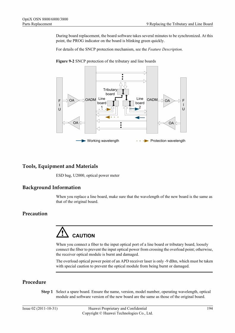
During board replacement, the board software takes several minutes to be synchronized. At thispoint, the PROG indicator on the board is blinking green quickly.
For details of the SNCP protection mechanism, see the Feature Description.
Figure 9-2 SNCP protection of the tributary and line boards
OA
OA
OA
OA
FIU
FIU
OADM OADM
Tributaryboard
Lineboard
1
Lineboard
2
Working wavelength Protection wavelength
Tools, Equipment and Materials
ESD bag, U2000, optical power meter
Background Information
When you replace a line board, make sure that the wavelength of the new board is the same asthat of the original board.
Precaution
CAUTIONWhen you connect a fiber to the input optical port of a line board or tributary board, looselyconnect the fiber to prevent the input optical power from crossing the overload point; otherwise,the receiver optical module is burnt and damaged.The overload optical power point of an APD receiver laser is only -9 dBm, which must be takenwith special caution to prevent the optical module from being burnt or damaged.
Procedure
Step 1 Select a spare board. Ensure the name, version, model number, operating wavelength, opticalmodule and software version of the new board are the same as those of the original board.
OptiX OSN 8800/6800/3800Parts Replacement 9 Replacing the Tributary and Line Board
Issue 02 (2011-10-31) Huawei Proprietary and ConfidentialCopyright © Huawei Technologies Co., Ltd.
194
NOTE
If the version is inconsistent, you need to determine if the board with different versions can be replaced.For more information regarding the replacement relation between board versions, refer to the HardwareDescription.
Query the optical module information. For more information, refer to "Querying Optical ModuleInformation" of the Supporting Tasks.
Step 2 Review and record the current alarms on the NE. For more information, refer to "Querying theCurrent Alarms" of the Supporting Tasks.
NOTE
To replace a board in an upgrade, perform this operation to determine if abnormal alarms are generated on theNE where the board to be replaced resides and the downstream NE. If there are abnormal alarms, you need tohandle these alarms before replacing the board.
Step 3 Test the input optical power. Prevent the input optical power from crossing the overload point,otherwise, the receiver optical module is burnt and damaged. For the procedure, refer to theTesting Optical Power by Using an Optical Power Meter in Supporting Tasks.
Step 4 If you want to replace a line board, go to Step 5. If you want to replace a tributary board, go toStep 9.
Step 5 Follow the steps below to query the working state of the board to be replaced.
1. In the NE Explorer, click the NE and choose Configuration > WDM ServiceManagement from the Function Tree. Click the SNCP Service Control tab.
2. Click Query to obtain the SNCP protection state of each NE.
CAUTIONBefore maintaining trails configured with protection, perform forcible switching to ensurethat services are on the stable and available trail. This is to prevent abnormal protectionswitching caused by unstable operation of the protection group in the maintenance process.After maintenance, you can cancel the forcible switching to restore the normal state of theprotection group when both the working and protection trails are normal.
3. Select the desired service and click Function on the bottom of the right-hand pane. SelectQuery Switching Status from the menu displayed. Then, you can learn the service isworking on active path or working on standby path.
4. In the Operation Result dialog box, click Close to finish the operation.
Step 6 If the board is the current working board, go to Step 7. If the board is the current protectionboard, go to Step 9.
Step 7 If the board to be replaced is the current working board, follow the steps below to perform anactive/standby switching on the U2000.
NOTE
The channel status of the protection board must be normal. Otherwise, replacing the faulty board causes aservice interruption.
1. In the Main Topology, right-click the desire NE and click NE Explorer from the shortcutmenu. The NE Explorer window is displayed.
2. Choose Configuration > WDM Service Management from the Function Tree.
OptiX OSN 8800/6800/3800Parts Replacement 9 Replacing the Tributary and Line Board
Issue 02 (2011-10-31) Huawei Proprietary and ConfidentialCopyright © Huawei Technologies Co., Ltd.
195

3. Click SNCP Service Control tab.4. Click Function on the right-hand interface and select Manual to Protection from the menu
displayed. Click OK on the interface displayed.5. Click Function on the right-hand interface and select Query Switching Status from the
menu displayed. If Manual(from working to protection) switching state is displayed inthe Status field, the switching succeeds.
6. Query the U2000 for the alarms and performance events. Make sure that there are no newalarms or performance events and services are normal but only protection switching alarm.
Step 8 At the opposite end perform a manual switching on the U2000 to ensure that the working channelat the opposite end and is consistent with that at the local end. For how to perform a manualswitching, see Step 7.
NOTEYou do not need to perform a manual switching at the opposite end before replacing the tributary board in theSNCP protection group.
Step 9 Inform the onsite maintenance engineer and replace the board. For more information regardinghow to replace a board, refer to "Replacing a Board" of the Supporting Tasks.
OptiX OSN 8800/6800/3800Parts Replacement 9 Replacing the Tributary and Line Board
Issue 02 (2011-10-31) Huawei Proprietary and ConfidentialCopyright © Huawei Technologies Co., Ltd.
196
NOTE
l If the software version of the spare board is V100R004C01 or earlier, perform the following operationsbefore replacing the board:
l If the board is installed in the OptiX OSN 3800 subrack, no operation is required.
l If the OptiX OSN 8800 T64 functions as the master subrack, you need to take the following actionson the replacement board before replacing any original board on the NE. Otherwise, the services of theactive boards in other slots may be interrupted.
l a. Install the spare board to any available slot of the OptiX OSN 6800 subrack of versionV100R004C02 or later. Note that the master subrack of the NE where the OptiX OSN 6800 subrackis located cannot be OptiX OSN 8800 T64. For more information regarding the valid slots of theboard, see "Valid Slots" in the Hardware Description.
l b. When the replacement board is in service, review the indicators on the board. If any indicatorflashes abnormally, reset or replace the replacement board. For description of the indicators, see"Indicator" in the Hardware Description.
l c. Double-click the icon of the optical NE in the Physical View, and the NE Panel is displayed.Click the NE where the replacement board resides.
l d. Right-click the slot where the replacement board resides. Choose Add Physical Board from theshortcut menu.
l e. Right-click the slot where the replacement board resides. Choose Version from the shortcutmenu to query the board software version information, and record the displayed versioninformation.
l f. Right click the slot where the replacement board resides. Choose Delete from the shortcut menu.
l g. Right-click the slot where the board to be replaced or the board with the same type as the boardto be replaced resides. Choose Version from the shortcut menu. If the version is the same as thatrecorded in Step e, it indicates that the process of the replacement board is successful. Otherwise,reset or replace the replacement board, and repeat Steps a to g.
l h. Remove the replacement board, and the process of the replacement board is complete.
l i. Replace the fault board. For more information, refer to "Replacing a Board" of the SupportingTasks.
l If the OptiX OSN 8800 T64 does not function as the master subrack, and the board to be replaced isin any slot of the OptiX OSN 8800 T32 or OptiX OSN 8800 T64 subrack on the NE, you need toperform the following operations on the replacement board before replacing the original board.Otherwise, the services of the active boards in other slots may be interrupted. If the board is installedin the OptiX OSN 6800 subrack, no operation is required.
l a. Install the spare board in any available slot of the OptiX OSN 6800 subrack of versionV100R004C02 or later. For more information regarding the valid slots of the board, see "ValidSlots" in the Hardware Description.
l b. For other operations, see the previous steps b to i.
NOTE
After the board is replaced, the NE software delivers the configuration of the original board automatically.
Step 10 Review the indicators of the new board. It takes ten minutes for a new board to work normallyafter insertion. Ensure that the STAT indicator is steady green. If the indicator gives abnormalindication, you need to reinsert the board, or replace the board again. For more informationregarding indicator definitions, refer to "Indicators" of the Hardware Description.
Step 11 When you replace a line board, review on the U2000 the wavelength of the new board. Makesure the wavelength is the same as that of the original board.
1. In the NE Explorer, select the desired board and choose Configuration > WDMInterface from the Function Tree.
2. Select By Function, and then select Band Type/Wavelength No./Wavelength(nm)/Frequency(THz) from the drop-down list.
OptiX OSN 8800/6800/3800Parts Replacement 9 Replacing the Tributary and Line Board
Issue 02 (2011-10-31) Huawei Proprietary and ConfidentialCopyright © Huawei Technologies Co., Ltd.
197

3. Click Query to view Band Type/Wavelength No./Wavelength(nm)/Frequency(THz)of each optical port.
NOTE
If the replaced board is a tunable line board, after the board is replaced, the SCC delivers the wavelengthconfiguration of the original board automatically.
Step 12 Follow the steps below to cancel the switching.
1. In the Main Topology, right-click the desire NE and click NE Explorer from the shortcutmenu. The NE Explorer window is displayed.
2. Choose Configuration > WDM Service Management in the Function Tree.3. Click SNCP Service Control tab.4. Select the switched service, and click Function on the right-hand interface. Select Clear
from the menu displayed.5. Click Query, and review Status. If the value is Normal State, the switching succeeds.
Step 13 Query the 15-minute BER before FEC at the receive end of the link. Make sure that the BERbefore FEC does not deteriorate greatly from the value before board replacement.
1. Choose Performance > Browse WDM Performance from the Main Menu of theU2000, and then click the Current Performance Data tab.
2. Choose the desired boards in the left pane, and click the double-right-arrow button (red).3. Choose the option from the drop-down list next to Monitored Object Filter Condition.4. In Monitor Period, select 15-Minute.5. Click Count option button. Select options under Performance Event Type, and select
Display Zero Data for the Display Options.6. Click Query to query the performance value for bit error on the NE side.7. In the Operation Result dialog box, click Close to finish the operation.8. In the Monitored Object, FEC_BEF_COR_ER represents the BER before FEC.
Step 14 Query alarms and performances of the local NE and of the opposite NE and confirm that theoriginal alarms or performances are cleared.
----End
9.3 Under ODUk SPRing ProtectionThis section describes how to replace a line board or a tributary board when ODUk SPRingprotection is configured.
PrerequisiteYou must be an NMS user with "NE and network operator" authority or higher.
Impact on SystemWhen ODUk SPRing protection is configured,l In the case of two-fiber ring, replacing a tributary board or a line board brings a service
interruption.l In the case of four-fiber ring, replacing a tributary board brings a service interruption.
OptiX OSN 8800/6800/3800Parts Replacement 9 Replacing the Tributary and Line Board
Issue 02 (2011-10-31) Huawei Proprietary and ConfidentialCopyright © Huawei Technologies Co., Ltd.
198

Replacing a line board brings no service interruption in case of a normal switching.
Figure 9-3 illustrates an application of four-fiber ring. As shown in the figure, the NS2 isconfigured with ODUk SPRing protection. Replacing the TOM brings a service interruption.Replacing the NS2 brings no service interruption in case of a normal switching.
During board replacement, the board software takes several minutes to be synchronized. At thispoint, the PROG indicator on the board is blinking green quickly.
For details of the ODUk SPRing protection mechanism, see the Feature Description.
Figure 9-3 ODUk SPRing protection of the tributary and line boards
West East
Working ODUk Proteciotn ODUk
NS2
TOM
NS2
NS2 NS2
Tools, Equipment and Materials
ESD bag, U2000, optical power meter
Background Information
When you replace a line board, make sure that the wavelength of the new board is the same asthat of the original board.
Precaution
CAUTIONWhen you connect a fiber to the input optical port of a line board or tributary board, looselyconnect the fiber to prevent the input optical power from crossing the overload point; otherwise,the receiver optical module is burnt and damaged.
The overload optical power point of an APD receiver laser is only -9 dBm, which must be takenwith special caution to prevent the optical module from being burnt or damaged.
OptiX OSN 8800/6800/3800Parts Replacement 9 Replacing the Tributary and Line Board
Issue 02 (2011-10-31) Huawei Proprietary and ConfidentialCopyright © Huawei Technologies Co., Ltd.
199
Procedure
Step 1 Select a spare board. Ensure the name, version, model number, operating wavelength, opticalmodule and software version of the new board are the same as those of the original board.
NOTE
If the version is inconsistent, you need to determine if the board with different versions can be replaced.For more information regarding the replacement relation between board versions, refer to the HardwareDescription.
Query the optical module information. For more information, refer to "Querying Optical ModuleInformation" of the Supporting Tasks.
Step 2 Review and record the current alarms on the NE. For more information, refer to "Querying theCurrent Alarms" of the Supporting Tasks.
NOTE
To replace a board in an upgrade, perform this operation to determine if abnormal alarms are generated on theNE where the board to be replaced resides and the downstream NE. If there are abnormal alarms, you need tohandle these alarms before replacing the board.
Step 3 If you want to replace a line board, go to Step 4. If you want to replace a tributary board, go toStep 7.
Step 4 Follow the steps below to query the working state of the board to be replaced:
1. In the NE Explorer, click the NE and choose Configuration > ODUk SPRing from theFunction Tree.
2. Click Query to query the switching status of the current protection group.
CAUTIONBefore maintaining trails configured with protection, perform forcible switching to ensurethat services are on the stable and available trail. This is to prevent abnormal protectionswitching caused by unstable operation of the protection group in the maintenance process.After maintenance, you can cancel the forcible switching to restore the normal state of theprotection group when both the working and protection trails are normal.
Step 5 If the board is the current working board, go to Step 6. If the board is the current protectionboard, go to Step 7.
Step 6 If the board to be replaced is the current working board, follow the steps below to perform anactive/standby switching on the U2000.
NOTE
The channel status of the protection board must be normal. Otherwise, replacing the faulty board causes aservice interruption.
1. In the Main Topology, right-click the desire NE and click NE Explorer from the shortcutmenu. The NE Explorer window is displayed.
2. Choose Configuration > ODUk SPRing from the Function Tree.3. Right-click the desired Protection Unit and select Manual Switching –Ringfrom the
menu displayed. Click OK on the interface displayed.4. Click Query on the right-hand interface. If Manual Switching –Ring is displayed, the
switching succeeds.
OptiX OSN 8800/6800/3800Parts Replacement 9 Replacing the Tributary and Line Board
Issue 02 (2011-10-31) Huawei Proprietary and ConfidentialCopyright © Huawei Technologies Co., Ltd.
200

5. Query the U2000 for the alarms and performance events. Make sure that there are no newalarms or performance events and services are normal but only ODUKSP_PS. Theswitching succeeds.
Step 7 Test the input optical power. Prevent the input optical power from crossing the overload point,otherwise, the receiver optical module is burnt and damaged. For the procedure, refer to theTesting Optical Power by Using an Optical Power Meter in Supporting Tasks.
Step 8 Inform the onsite maintenance engineer and replace the board. For more information regardinghow to replace a board, refer to "Replacing a Board" of the Supporting Tasks.
NOTE
l If the software version of the spare board is V100R004C01 or earlier, perform the following operationsbefore replacing the board:
l If the board is installed in the OptiX OSN 3800 subrack, no operation is required.
l If the OptiX OSN 8800 T64 functions as the master subrack, you need to take the following actionson the replacement board before replacing any original board on the NE. Otherwise, the services of theactive boards in other slots may be interrupted.
l a. Install the spare board to any available slot of the OptiX OSN 6800 subrack of versionV100R004C02 or later. Note that the master subrack of the NE where the OptiX OSN 6800 subrackis located cannot be OptiX OSN 8800 T64. For more information regarding the valid slots of theboard, see "Valid Slots" in the Hardware Description.
l b. When the replacement board is in service, review the indicators on the board. If any indicatorflashes abnormally, reset or replace the replacement board. For description of the indicators, see"Indicator" in the Hardware Description.
l c. Double-click the icon of the optical NE in the Physical View, and the NE Panel is displayed.Click the NE where the replacement board resides.
l d. Right-click the slot where the replacement board resides. Choose Add Physical Board from theshortcut menu.
l e. Right-click the slot where the replacement board resides. Choose Version from the shortcutmenu to query the board software version information, and record the displayed versioninformation.
l f. Right click the slot where the replacement board resides. Choose Delete from the shortcut menu.
l g. Right-click the slot where the board to be replaced or the board with the same type as the boardto be replaced resides. Choose Version from the shortcut menu. If the version is the same as thatrecorded in Step e, it indicates that the process of the replacement board is successful. Otherwise,reset or replace the replacement board, and repeat Steps a to g.
l h. Remove the replacement board, and the process of the replacement board is complete.
l i. Replace the fault board. For more information, refer to "Replacing a Board" of the SupportingTasks.
l If the OptiX OSN 8800 T64 does not function as the master subrack, and the board to be replaced isin any slot of the OptiX OSN 8800 T32 or OptiX OSN 8800 T64 subrack on the NE, you need toperform the following operations on the replacement board before replacing the original board.Otherwise, the services of the active boards in other slots may be interrupted. If the board is installedin the OptiX OSN 6800 subrack, no operation is required.
l a. Install the spare board in any available slot of the OptiX OSN 6800 subrack of versionV100R004C02 or later. For more information regarding the valid slots of the board, see "ValidSlots" in the Hardware Description.
l b. For other operations, see the previous steps b to i.
NOTE
After the board is replaced, the NE software delivers the configuration of the original board automatically.
Step 9 Review the indicators of the new board. It takes ten minutes for a new board to work normallyafter insertion. Ensure that the STAT indicator is steady green. If the indicator gives abnormal
OptiX OSN 8800/6800/3800Parts Replacement 9 Replacing the Tributary and Line Board
Issue 02 (2011-10-31) Huawei Proprietary and ConfidentialCopyright © Huawei Technologies Co., Ltd.
201
indication, you need to reinsert the board, or replace the board again. For more informationregarding indicator definitions, refer to "Indicators" of the Hardware Description.
Step 10 When you replace a line board, review on the U2000 the wavelength of the new board. Makesure the wavelength is the same as that of the original board.
1. In the NE Explorer, select the desired board and choose Configuration > WDMInterface from the Function Tree.
2. Select By Function, and then select Band Type/Wavelength No./Wavelength(nm)/Frequency(THz) from the drop-down list.
3. Click Query to view Band Type/Wavelength No./Wavelength(nm)/Frequency(THz)of each optical port.
NOTE
If the replaced board is a tunable line board, after the board is replaced, the SCC delivers the wavelengthconfiguration of the original board automatically.
Step 11 Follow the steps below to cancel the switching.
1. In the Main Topology, right-click the desire NE and click NE Explorer from the shortcutmenu. The NE Explorer window is displayed.
2. Choose Configuration > ODUk SPRing from the Function Tree.3. Right-click the switched service, and select Clear from the menu displayed.4. Click Query, and check Switching Status. If the value is Idle, the switching succeeds.
Step 12 Query the 15-minute BER before FEC at the receive end of the link. Make sure that the BERbefore FEC does not deteriorate greatly from the value before board replacement.
1. Choose Performance > Browse WDM Performance from the Main Menu of theU2000, and then click the Current Performance Data tab.
2. Choose the desired boards in the left pane, and click the double-right-arrow button (red).3. Choose the option from the drop-down list next to Monitored Object Filter Condition.4. In Monitor Period, select 15-Minute.5. Click Count option button. Select options under Performance Event Type, and select
Display Zero Data for the Display Options.6. Click Query to query the performance value for bit error on the NE side.7. In the Operation Result dialog box, click Close to finish the operation.8. In the Monitored Object, FEC_BEF_COR_ER represents the BER before FEC.
Step 13 Query alarms and performances of the local NE and of the opposite NE and confirm that theoriginal alarms or performances are cleared.
----End
9.4 Under DBPS ProtectionThis section describes how to replace the TBE board when no DBPS protection is configured.
Prerequisitel You must be an NMS user with "NE and network operator" authority or higher.
OptiX OSN 8800/6800/3800Parts Replacement 9 Replacing the Tributary and Line Board
Issue 02 (2011-10-31) Huawei Proprietary and ConfidentialCopyright © Huawei Technologies Co., Ltd.
202
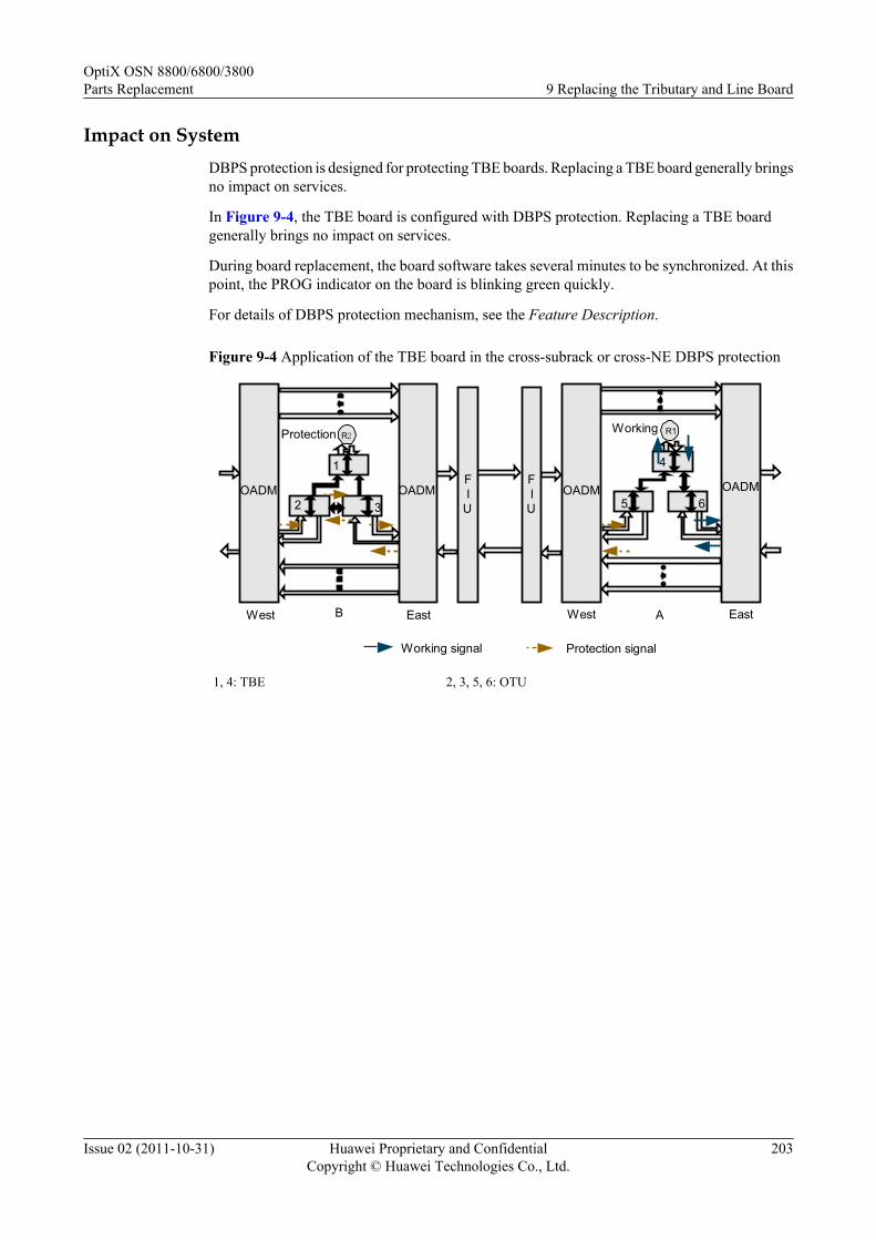
Impact on SystemDBPS protection is designed for protecting TBE boards. Replacing a TBE board generally bringsno impact on services.
In Figure 9-4, the TBE board is configured with DBPS protection. Replacing a TBE boardgenerally brings no impact on services.
During board replacement, the board software takes several minutes to be synchronized. At thispoint, the PROG indicator on the board is blinking green quickly.
For details of DBPS protection mechanism, see the Feature Description.
Figure 9-4 Application of the TBE board in the cross-subrack or cross-NE DBPS protection
A EastWestBWest East
1
2 3
4
5 6
R1Protection
OADMFI
FI
UFI
FI
UOADMOADMOADM
R2Working
Working signal Protection signal
1, 4: TBE 2, 3, 5, 6: OTU
OptiX OSN 8800/6800/3800Parts Replacement 9 Replacing the Tributary and Line Board
Issue 02 (2011-10-31) Huawei Proprietary and ConfidentialCopyright © Huawei Technologies Co., Ltd.
203

Figure 9-5 Application of the TBE board in the intra-subrack DBPS protection
R2 WorkingProtection
West East
2
3 4
1OADM OADM
Working signal
R1
Protection signal
1, 2: TBE 3, 4: OTU
Tools, Equipment and MaterialsESD bag, U2000, optical power meter
Precaution
CAUTIONWhen you connect a fiber to the input optical port of a line board or tributary board, looselyconnect the fiber to prevent the input optical power from crossing the overload point; otherwise,the receiver optical module is burnt and damaged.The overload optical power point of an APD receiver laser is only -9 dBm, which must be takenwith special caution to prevent the optical module from being burnt or damaged.
Procedure
Step 1 Select a spare board. Ensure the name, version, model number, optical module and softwareversion of the new board are the same as those of the original board.
NOTE
If the version is inconsistent, you need to determine if the board with different versions can be replaced.For more information regarding the replacement relation between board versions, refer to the HardwareDescription.
Query the optical module information. For more information, refer to "Querying Optical ModuleInformation" of the Supporting Tasks.
Step 2 Review and record the current alarms on the NE. For more information, refer to "Querying theCurrent Alarms" of the Supporting Tasks.
OptiX OSN 8800/6800/3800Parts Replacement 9 Replacing the Tributary and Line Board
Issue 02 (2011-10-31) Huawei Proprietary and ConfidentialCopyright © Huawei Technologies Co., Ltd.
204

NOTE
To replace a board in an upgrade, perform this operation to determine if abnormal alarms are generated on theNE where the board to be replaced resides and the downstream NE. If there are abnormal alarms, you need tohandle these alarms before replacing the board.
Step 3 Follow the steps below to query the working state of the board to be replaced:
1. In the NE Explorer, click the NE and choose Configuration > Distributed Board-LevelProtection from the Function Tree.
2. Click Query to obtain the created DBPS protection group and associated VLAN of theprotection group.
Step 4 If the working status of the board to be replaced is Master, go to Step 5. If the working statusof the board to be replaced is not Master, go to Step 7.
Step 5 Remove the fiber in the board to be replaced which connect to the BRAS, and the service willswitch to the current protection board.
NOTE
The channel status of the protection board must be Slave. Otherwise, replacing the faulty board causes aservice interruption.
Cover a fiber with a protection cap immediately after you remove it.
Step 6 Query the U2000 for the alarms and performance events. Make sure that there are no new alarmsor performance events and services are normal. The switching succeeds. For detailed procedures,see "Querying the Current Alarms" of the Supporting Tasks.
Step 7 Test the input optical power. Prevent the input optical power from crossing the overload point,otherwise, the receiver optical module is burnt and damaged. For the procedure, refer to theTesting Optical Power by Using an Optical Power Meter in Supporting Tasks.
Step 8 Inform the onsite maintenance engineer and replace the board. For more information regardinghow to replace a board, refer to "Replacing a Board" of the Supporting Tasks.
OptiX OSN 8800/6800/3800Parts Replacement 9 Replacing the Tributary and Line Board
Issue 02 (2011-10-31) Huawei Proprietary and ConfidentialCopyright © Huawei Technologies Co., Ltd.
205

NOTE
l If the software version of the spare board is V100R004C01 or earlier, perform the following operationsbefore replacing the board:
l If the board is installed in the OptiX OSN 3800 subrack, no operation is required.
l If the OptiX OSN 8800 T64 functions as the master subrack, you need to take the following actionson the replacement board before replacing any original board on the NE. Otherwise, the services of theactive boards in other slots may be interrupted.
l a. Install the spare board to any available slot of the OptiX OSN 6800 subrack of versionV100R004C02 or later. Note that the master subrack of the NE where the OptiX OSN 6800 subrackis located cannot be OptiX OSN 8800 T64. For more information regarding the valid slots of theboard, see "Valid Slots" in the Hardware Description.
l b. When the replacement board is in service, review the indicators on the board. If any indicatorflashes abnormally, reset or replace the replacement board. For description of the indicators, see"Indicator" in the Hardware Description.
l c. Double-click the icon of the optical NE in the Physical View, and the NE Panel is displayed.Click the NE where the replacement board resides.
l d. Right-click the slot where the replacement board resides. Choose Add Physical Board from theshortcut menu.
l e. Right-click the slot where the replacement board resides. Choose Version from the shortcutmenu to query the board software version information, and record the displayed versioninformation.
l f. Right click the slot where the replacement board resides. Choose Delete from the shortcut menu.
l g. Right-click the slot where the board to be replaced or the board with the same type as the boardto be replaced resides. Choose Version from the shortcut menu. If the version is the same as thatrecorded in Step e, it indicates that the process of the replacement board is successful. Otherwise,reset or replace the replacement board, and repeat Steps a to g.
l h. Remove the replacement board, and the process of the replacement board is complete.
l i. Replace the fault board. For more information, refer to "Replacing a Board" of the SupportingTasks.
l If the OptiX OSN 8800 T64 does not function as the master subrack, and the board to be replaced isin any slot of the OptiX OSN 8800 T32 or OptiX OSN 8800 T64 subrack on the NE, you need toperform the following operations on the replacement board before replacing the original board.Otherwise, the services of the active boards in other slots may be interrupted. If the board is installedin the OptiX OSN 6800 subrack, no operation is required.
l a. Install the spare board in any available slot of the OptiX OSN 6800 subrack of versionV100R004C02 or later. For more information regarding the valid slots of the board, see "ValidSlots" in the Hardware Description.
l b. For other operations, see the previous steps b to i.
NOTE
After the board is replaced, the NE software delivers the configuration of the original board automatically.
Step 9 Review the indicators of the new board. It takes ten minutes for a new board to work normallyafter insertion. Ensure that the STAT indicator is steady green. If the indicator gives abnormalindication, you need to reinsert the board, or replace the board again. For more informationregarding indicator definitions, refer to "Indicators" of the Hardware Description.
Step 10 Query the 15-minute BER before FEC at the receive end of the link. Make sure that the BERbefore FEC does not deteriorate greatly from the value before board replacement.
1. Choose Performance > Browse WDM Performance from the Main Menu of theU2000, and then click the Current Performance Data tab.
2. Choose the desired boards in the left pane, and click the double-right-arrow button (red).3. Choose the option from the drop-down list next to Monitored Object Filter Condition.
OptiX OSN 8800/6800/3800Parts Replacement 9 Replacing the Tributary and Line Board
Issue 02 (2011-10-31) Huawei Proprietary and ConfidentialCopyright © Huawei Technologies Co., Ltd.
206

4. In Monitor Period, select 15-Minute.5. Click Count option button. Select options under Performance Event Type, and select
Display Zero Data for the Display Options.6. Click Query to query the performance value for bit error on the NE side.7. In the Operation Result dialog box, click Close to finish the operation.8. In the Monitored Object, FEC_BEF_COR_ER represents the BER before FEC.
Step 11 Query alarms and performances of the local NE and of the opposite NE and confirm that theoriginal alarms or performances are cleared.
----End
9.5 Under DLAG ProtectionThis section describes how to replace the TBE board when DLAG protection is configured.
Prerequisitel You must be an NMS user with "NE and network operator" authority or higher.
Impact on SystemDLAG protection is designed for protecting TBE boards. Replacing a TBE board generallybrings no impact on services.
During board replacement, the board software takes several minutes to be synchronized. At thispoint, the PROG indicator on the board is blinking green quickly.
For details of DLAG protection mechanism, see the Feature Description.
Figure 9-6 DLAG protection of the TBE board
West East
2
3 4
1OADM
DSLAM
OADM
Working signal Protection signal
ProtectionWorking
1, 2: TBE 3, 4: OTU
OptiX OSN 8800/6800/3800Parts Replacement 9 Replacing the Tributary and Line Board
Issue 02 (2011-10-31) Huawei Proprietary and ConfidentialCopyright © Huawei Technologies Co., Ltd.
207

Tools, Equipment and Materials
ESD bag, U2000, optical power meter
Precaution
CAUTIONWhen you connect a fiber to the input optical port of a line board or tributary board, looselyconnect the fiber to prevent the input optical power from crossing the overload point; otherwise,the receiver optical module is burnt and damaged.The overload optical power point of an APD receiver laser is only -9 dBm, which must be takenwith special caution to prevent the optical module from being burnt or damaged.
Procedure
Step 1 Select a spare board. Ensure the name, version, model number, optical module and softwareversion of the new board are the same as those of the original board.
NOTE
If the version is inconsistent, you need to determine if the board with different versions can be replaced.For more information regarding the replacement relation between board versions, refer to the HardwareDescription.
Query the optical module information. For more information, refer to "Querying Optical ModuleInformation" of the Supporting Tasks.
Step 2 Review and record the current alarms on the NE. For more information, refer to "Querying theCurrent Alarms" of the Supporting Tasks.
NOTE
To replace a board in an upgrade, perform this operation to determine if abnormal alarms are generated on theNE where the board to be replaced resides and the downstream NE. If there are abnormal alarms, you need tohandle these alarms before replacing the board.
Step 3 Follow the steps below to query the working state of the board to be replaced:
1. In the NE Explorer, click the NE and choose Configuration > Ethernet Distributed LinkAggregation Management from the Function Tree.
2. Click Query in the right pane. The parameters of the current protection group can bequeried.
Step 4 If the board to be replaced is the working board, go to Step 5. If the board to be replaced is notthe working board, go to Step 6.
Step 5 Remove the fiber in the board to be replaced which connect to the DSLAM, and the service willswitch to the current protection board.
NOTE
Query the current alarms on the U2000. For details, see"Querying the Current Alarms" of the SupportingTasks, There must be no DLAG_PROTECT_FAIL alarm reported, otherwise, replacing the faulty boardcauses a service interruption.
Cover a fiber with a protection cap immediately after you remove it.
OptiX OSN 8800/6800/3800Parts Replacement 9 Replacing the Tributary and Line Board
Issue 02 (2011-10-31) Huawei Proprietary and ConfidentialCopyright © Huawei Technologies Co., Ltd.
208

Step 6 Test the input optical power. Prevent the input optical power from crossing the overload point,otherwise, the receiver optical module is burnt and damaged. For the procedure, refer to theTesting Optical Power by Using an Optical Power Meter in Supporting Tasks.
Step 7 Inform the onsite maintenance engineer and replace the board. For more information regardinghow to replace a board, refer to "Replacing a Board" of the Supporting Tasks.
NOTE
l If the software version of the spare board is V100R004C01 or earlier, perform the following operationsbefore replacing the board:
l If the board is installed in the OptiX OSN 3800 subrack, no operation is required.l If the OptiX OSN 8800 T64 functions as the master subrack, you need to take the following actions
on the replacement board before replacing any original board on the NE. Otherwise, the services of theactive boards in other slots may be interrupted.l a. Install the spare board to any available slot of the OptiX OSN 6800 subrack of version
V100R004C02 or later. Note that the master subrack of the NE where the OptiX OSN 6800 subrackis located cannot be OptiX OSN 8800 T64. For more information regarding the valid slots of theboard, see "Valid Slots" in the Hardware Description.
l b. When the replacement board is in service, review the indicators on the board. If any indicatorflashes abnormally, reset or replace the replacement board. For description of the indicators, see"Indicator" in the Hardware Description.
l c. Double-click the icon of the optical NE in the Physical View, and the NE Panel is displayed.Click the NE where the replacement board resides.
l d. Right-click the slot where the replacement board resides. Choose Add Physical Board from theshortcut menu.
l e. Right-click the slot where the replacement board resides. Choose Version from the shortcutmenu to query the board software version information, and record the displayed versioninformation.
l f. Right click the slot where the replacement board resides. Choose Delete from the shortcut menu.l g. Right-click the slot where the board to be replaced or the board with the same type as the board
to be replaced resides. Choose Version from the shortcut menu. If the version is the same as thatrecorded in Step e, it indicates that the process of the replacement board is successful. Otherwise,reset or replace the replacement board, and repeat Steps a to g.
l h. Remove the replacement board, and the process of the replacement board is complete.l i. Replace the fault board. For more information, refer to "Replacing a Board" of the Supporting
Tasks.l If the OptiX OSN 8800 T64 does not function as the master subrack, and the board to be replaced is
in any slot of the OptiX OSN 8800 T32 or OptiX OSN 8800 T64 subrack on the NE, you need toperform the following operations on the replacement board before replacing the original board.Otherwise, the services of the active boards in other slots may be interrupted. If the board is installedin the OptiX OSN 6800 subrack, no operation is required.l a. Install the spare board in any available slot of the OptiX OSN 6800 subrack of version
V100R004C02 or later. For more information regarding the valid slots of the board, see "ValidSlots" in the Hardware Description.
l b. For other operations, see the previous steps b to i.
NOTE
After the board is replaced, the NE software delivers the configuration of the original board automatically.
Step 8 Review the indicators of the new board. It takes ten minutes for a new board to work normallyafter insertion. Ensure that the STAT indicator is steady green. If the indicator gives abnormalindication, you need to reinsert the board, or replace the board again. For more informationregarding indicator definitions, refer to "Indicators" of the Hardware Description.
Step 9 Query the 15-minute BER before FEC at the receive end of the link. Make sure that the BERbefore FEC does not deteriorate greatly from the value before board replacement.
OptiX OSN 8800/6800/3800Parts Replacement 9 Replacing the Tributary and Line Board
Issue 02 (2011-10-31) Huawei Proprietary and ConfidentialCopyright © Huawei Technologies Co., Ltd.
209

1. Choose Performance > Browse WDM Performance from the Main Menu of theU2000, and then click the Current Performance Data tab.
2. Choose the desired boards in the left pane, and click the double-right-arrow button (red).
3. Choose the option from the drop-down list next to Monitored Object Filter Condition.
4. In Monitor Period, select 15-Minute.
5. Click Count option button. Select options under Performance Event Type, and selectDisplay Zero Data for the Display Options.
6. Click Query to query the performance value for bit error on the NE side.
7. In the Operation Result dialog box, click Close to finish the operation.
8. In the Monitored Object, FEC_BEF_COR_ER represents the BER before FEC.
Step 10 Query alarms and performances of the local NE and of the opposite NE and confirm that theoriginal alarms or performances are cleared.
----End
9.6 Under Board-Level ProtectionThis section describes how to replace a TBE board when board-level protection is configured.
Prerequisitel You must be an NMS user with "NE and network operator" authority or higher.
Impact on System
Board-level protection is designed for protecting TBE boards. Replacing a TBE board bringsno service interruption in case of a normal switching.
During board replacement, the board software takes several minutes to be synchronized. At thispoint, the PROG indicator on the board is blinking green quickly.
For details of board-level protection mechanism, see the Feature Description.
Figure 9-7 Board-level protection of the TBE board
OD
OM
FIU
FIU
OM
OD
L4G
TBE1
TBE2
TBE1
TBE2
L4G
R1
R2
R1
R2
Working signal Protection signal
TBE1
TBE2
TBE1
TBE2
OptiX OSN 8800/6800/3800Parts Replacement 9 Replacing the Tributary and Line Board
Issue 02 (2011-10-31) Huawei Proprietary and ConfidentialCopyright © Huawei Technologies Co., Ltd.
210

Tools, Equipment and MaterialsESD bag, U2000, optical power meter
Precaution
CAUTIONWhen you connect a fiber to the input optical port of a line board or tributary board, looselyconnect the fiber to prevent the input optical power from crossing the overload point; otherwise,the receiver optical module is burnt and damaged.The overload optical power point of an APD receiver laser is only -9 dBm, which must be takenwith special caution to prevent the optical module from being burnt or damaged.
Procedure
Step 1 Select a spare board. Ensure the name, version, model number, optical module and softwareversion of the new board are the same as those of the original board.
NOTE
If the version is inconsistent, you need to determine if the board with different versions can be replaced.For more information regarding the replacement relation between board versions, refer to the HardwareDescription.
Query the optical module information. For more information, refer to "Querying Optical ModuleInformation" of the Supporting Tasks.
Step 2 Review and record the current alarms on the NE. For more information, refer to "Querying theCurrent Alarms" of the Supporting Tasks.
NOTE
To replace a board in an upgrade, perform this operation to determine if abnormal alarms are generated on theNE where the board to be replaced resides and the downstream NE. If there are abnormal alarms, you need tohandle these alarms before replacing the board.
Step 3 Follow the steps below to query the working state of the board to be replaced:
1. In the NE Explorer, click the NE and choose Configuration > Board-Level Protectionfrom the Function Tree.
2. Click Query to query the switching status of the current protection group.
CAUTIONBefore maintaining trails configured with protection, perform forcible switching to ensurethat services are on the stable and available trail. This is to prevent abnormal protectionswitching caused by unstable operation of the protection group in the maintenance process.After maintenance, you can cancel the forcible switching to restore the normal state of theprotection group when both the working and protection trails are normal.
Step 4 If the board is the current working board, go to Step 5. If the board is the current protectionboard, go to Step 6.
OptiX OSN 8800/6800/3800Parts Replacement 9 Replacing the Tributary and Line Board
Issue 02 (2011-10-31) Huawei Proprietary and ConfidentialCopyright © Huawei Technologies Co., Ltd.
211

Step 5 If the board to be replaced is the current working board, follow the steps below to perform anactive/standby switching on the U2000.
NOTE
The channel status of the protection board must be Normal. Otherwise, replacing the faulty board causesa service interruption.
1. In the Main Topology, right-click the desire NE and click NE Explorer from the shortcutmenu. The NE Explorer window is displayed.
2. Choose Configuration > Board-Level Protection from the Function Tree.3. Click Function on the right-hand interface and select Manual Switching to Protection
from the menu displayed. Click OK on the interface displayed.4. Click Query on the right-hand interface. If Manual Switch Request is displayed, the
switching succeeds.5. Query the U2000 for the alarms and performance events. Make sure that there are no new
alarms or performance events and services are normal. The switching succeeds.
Step 6 Test the input optical power. Prevent the input optical power from crossing the overload point,otherwise, the receiver optical module is burnt and damaged. For the procedure, refer to theTesting Optical Power by Using an Optical Power Meter in Supporting Tasks.
Step 7 Inform the onsite maintenance engineer and replace the board. For more information regardinghow to replace a board, refer to "Replacing a Board" of the Supporting Tasks.
OptiX OSN 8800/6800/3800Parts Replacement 9 Replacing the Tributary and Line Board
Issue 02 (2011-10-31) Huawei Proprietary and ConfidentialCopyright © Huawei Technologies Co., Ltd.
212

NOTE
l If the software version of the spare board is V100R004C01 or earlier, perform the following operationsbefore replacing the board:
l If the board is installed in the OptiX OSN 3800 subrack, no operation is required.
l If the OptiX OSN 8800 T64 functions as the master subrack, you need to take the following actionson the replacement board before replacing any original board on the NE. Otherwise, the services of theactive boards in other slots may be interrupted.
l a. Install the spare board to any available slot of the OptiX OSN 6800 subrack of versionV100R004C02 or later. Note that the master subrack of the NE where the OptiX OSN 6800 subrackis located cannot be OptiX OSN 8800 T64. For more information regarding the valid slots of theboard, see "Valid Slots" in the Hardware Description.
l b. When the replacement board is in service, review the indicators on the board. If any indicatorflashes abnormally, reset or replace the replacement board. For description of the indicators, see"Indicator" in the Hardware Description.
l c. Double-click the icon of the optical NE in the Physical View, and the NE Panel is displayed.Click the NE where the replacement board resides.
l d. Right-click the slot where the replacement board resides. Choose Add Physical Board from theshortcut menu.
l e. Right-click the slot where the replacement board resides. Choose Version from the shortcutmenu to query the board software version information, and record the displayed versioninformation.
l f. Right click the slot where the replacement board resides. Choose Delete from the shortcut menu.
l g. Right-click the slot where the board to be replaced or the board with the same type as the boardto be replaced resides. Choose Version from the shortcut menu. If the version is the same as thatrecorded in Step e, it indicates that the process of the replacement board is successful. Otherwise,reset or replace the replacement board, and repeat Steps a to g.
l h. Remove the replacement board, and the process of the replacement board is complete.
l i. Replace the fault board. For more information, refer to "Replacing a Board" of the SupportingTasks.
l If the OptiX OSN 8800 T64 does not function as the master subrack, and the board to be replaced isin any slot of the OptiX OSN 8800 T32 or OptiX OSN 8800 T64 subrack on the NE, you need toperform the following operations on the replacement board before replacing the original board.Otherwise, the services of the active boards in other slots may be interrupted. If the board is installedin the OptiX OSN 6800 subrack, no operation is required.
l a. Install the spare board in any available slot of the OptiX OSN 6800 subrack of versionV100R004C02 or later. For more information regarding the valid slots of the board, see "ValidSlots" in the Hardware Description.
l b. For other operations, see the previous steps b to i.
NOTE
After the board is replaced, the NE software delivers the configuration of the original board automatically.
Step 8 Review the indicators of the new board. It takes ten minutes for a new board to work normallyafter insertion. Ensure that the STAT indicator is steady green. If the indicator gives abnormalindication, you need to reinsert the board, or replace the board again. For more informationregarding indicator definitions, refer to "Indicators" of the Hardware Description.
Step 9 Follow the steps below to cancel the switching.
1. In the Main Topology, right-click the desire NE and click NE Explorer from the shortcutmenu. The NE Explorer window is displayed.
2. Choose Configuration > Board-Level Protection from the Function Tree.3. Right-click the switched service, and select Clear from the menu displayed.4. Click Query, and check Switching Status. If the value is Idle, the switching is successful.
OptiX OSN 8800/6800/3800Parts Replacement 9 Replacing the Tributary and Line Board
Issue 02 (2011-10-31) Huawei Proprietary and ConfidentialCopyright © Huawei Technologies Co., Ltd.
213

Step 10 Query the 15-minute BER before FEC at the receive end of the link. Make sure that the BERbefore FEC does not deteriorate greatly from the value before board replacement.
1. Choose Performance > Browse WDM Performance from the Main Menu of theU2000, and then click the Current Performance Data tab.
2. Choose the desired boards in the left pane, and click the double-right-arrow button (red).
3. Choose the option from the drop-down list next to Monitored Object Filter Condition.
4. In Monitor Period, select 15-Minute.
5. Click Count option button. Select options under Performance Event Type, and selectDisplay Zero Data for the Display Options.
6. Click Query to query the performance value for bit error on the NE side.
7. In the Operation Result dialog box, click Close to finish the operation.
8. In the Monitored Object, FEC_BEF_COR_ER represents the BER before FEC.
Step 11 Query alarms and performances of the local NE and of the opposite NE and confirm that theoriginal alarms or performances are cleared.
----End
9.7 Under No ProtectionThis section describes how to replace a line board or a tributary board when no protection isconfigured.
PrerequisiteYou must be an NMS user with "NE and network operator" authority or higher.
Impact on System
Replacing an unprotected tributary or line board brings interruption of traditional services.
If the board to be replaced is a line board without protection and carries electrical-layer ASONservices, optimize the electrical-layer ASON services traversing the board to other line boards(the preset restoration paths of the services are preferred if they do not traverse the line board tobe replaced) before board replacement. Then, switch the services back to the original paths afterboard replacement. If the board to be replaced is a tributary board, the services will be interruptedduring board replacement.
During board replacement, the board software takes several minutes to be synchronized. At thispoint, the PROG indicator on the board is blinking green quickly.
Tools, Equipment and Materials
ESD bag, U2000, optical power meter
Background Information
When you replace a line board, make sure that the wavelength of the new board is the same asthat of the original board.
OptiX OSN 8800/6800/3800Parts Replacement 9 Replacing the Tributary and Line Board
Issue 02 (2011-10-31) Huawei Proprietary and ConfidentialCopyright © Huawei Technologies Co., Ltd.
214
Precaution
CAUTIONWhen you connect a fiber to the input optical port of a line board or tributary board, looselyconnect the fiber to prevent the input optical power from crossing the overload point; otherwise,the receiver optical module is burnt and damaged.The overload optical power point of an APD receiver laser is only -9 dBm, which must be takenwith special caution to prevent the optical module from being burnt or damaged.
Procedure
Step 1 Select a spare board. Ensure the name, version, model number, operating wavelength, opticalmodule and software version of the new board are the same as those of the original board.
NOTE
If the version is inconsistent, you need to determine if the board with different versions can be replaced.For more information regarding the replacement relation between board versions, refer to the HardwareDescription.
Query the optical module information. For more information, refer to "Querying Optical ModuleInformation" of the Supporting Tasks.
Step 2 Review and record the current alarms on the NE. For more information, refer to "Querying theCurrent Alarms" of the Supporting Tasks.
NOTE
To replace a board in an upgrade, perform this operation to determine if abnormal alarms are generated on theNE where the board to be replaced resides and the downstream NE. If there are abnormal alarms, you need tohandle these alarms before replacing the board.
Step 3 Test the input optical power. Prevent the input optical power from crossing the overload point,otherwise, the receiver optical module is burnt and damaged. For the procedure, refer to theTesting Optical Power by Using an Optical Power Meter in Supporting Tasks.
Step 4 Inform the onsite maintenance engineer and replace the board. For more information regardinghow to replace a board, refer to "Replacing a Board" of the Supporting Tasks.
OptiX OSN 8800/6800/3800Parts Replacement 9 Replacing the Tributary and Line Board
Issue 02 (2011-10-31) Huawei Proprietary and ConfidentialCopyright © Huawei Technologies Co., Ltd.
215
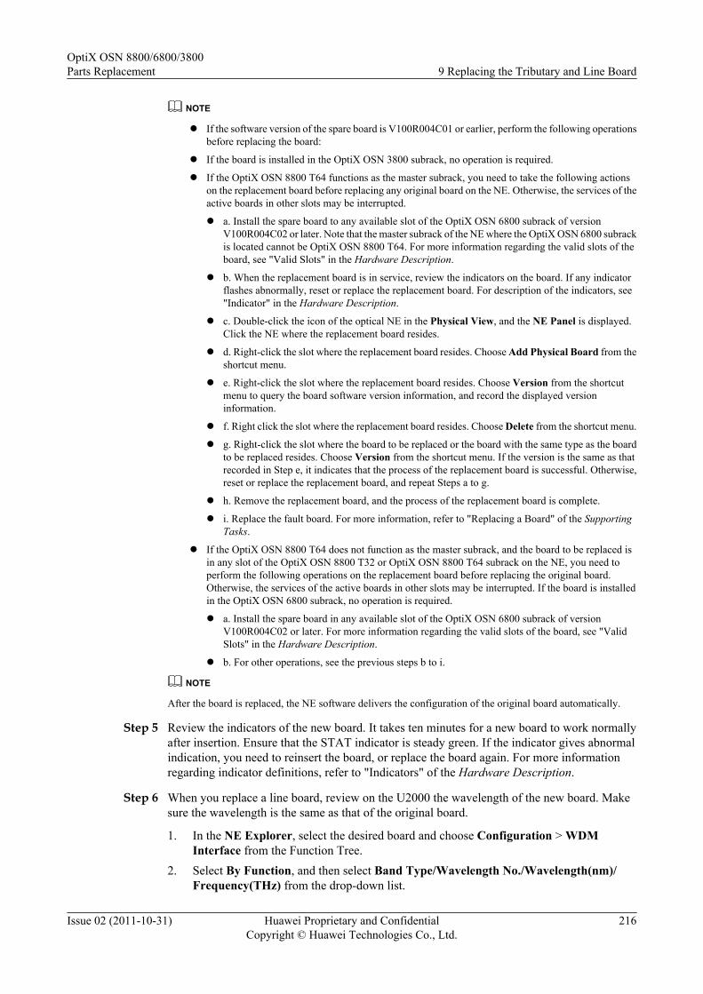
NOTE
l If the software version of the spare board is V100R004C01 or earlier, perform the following operationsbefore replacing the board:
l If the board is installed in the OptiX OSN 3800 subrack, no operation is required.
l If the OptiX OSN 8800 T64 functions as the master subrack, you need to take the following actionson the replacement board before replacing any original board on the NE. Otherwise, the services of theactive boards in other slots may be interrupted.
l a. Install the spare board to any available slot of the OptiX OSN 6800 subrack of versionV100R004C02 or later. Note that the master subrack of the NE where the OptiX OSN 6800 subrackis located cannot be OptiX OSN 8800 T64. For more information regarding the valid slots of theboard, see "Valid Slots" in the Hardware Description.
l b. When the replacement board is in service, review the indicators on the board. If any indicatorflashes abnormally, reset or replace the replacement board. For description of the indicators, see"Indicator" in the Hardware Description.
l c. Double-click the icon of the optical NE in the Physical View, and the NE Panel is displayed.Click the NE where the replacement board resides.
l d. Right-click the slot where the replacement board resides. Choose Add Physical Board from theshortcut menu.
l e. Right-click the slot where the replacement board resides. Choose Version from the shortcutmenu to query the board software version information, and record the displayed versioninformation.
l f. Right click the slot where the replacement board resides. Choose Delete from the shortcut menu.
l g. Right-click the slot where the board to be replaced or the board with the same type as the boardto be replaced resides. Choose Version from the shortcut menu. If the version is the same as thatrecorded in Step e, it indicates that the process of the replacement board is successful. Otherwise,reset or replace the replacement board, and repeat Steps a to g.
l h. Remove the replacement board, and the process of the replacement board is complete.
l i. Replace the fault board. For more information, refer to "Replacing a Board" of the SupportingTasks.
l If the OptiX OSN 8800 T64 does not function as the master subrack, and the board to be replaced isin any slot of the OptiX OSN 8800 T32 or OptiX OSN 8800 T64 subrack on the NE, you need toperform the following operations on the replacement board before replacing the original board.Otherwise, the services of the active boards in other slots may be interrupted. If the board is installedin the OptiX OSN 6800 subrack, no operation is required.
l a. Install the spare board in any available slot of the OptiX OSN 6800 subrack of versionV100R004C02 or later. For more information regarding the valid slots of the board, see "ValidSlots" in the Hardware Description.
l b. For other operations, see the previous steps b to i.
NOTE
After the board is replaced, the NE software delivers the configuration of the original board automatically.
Step 5 Review the indicators of the new board. It takes ten minutes for a new board to work normallyafter insertion. Ensure that the STAT indicator is steady green. If the indicator gives abnormalindication, you need to reinsert the board, or replace the board again. For more informationregarding indicator definitions, refer to "Indicators" of the Hardware Description.
Step 6 When you replace a line board, review on the U2000 the wavelength of the new board. Makesure the wavelength is the same as that of the original board.
1. In the NE Explorer, select the desired board and choose Configuration > WDMInterface from the Function Tree.
2. Select By Function, and then select Band Type/Wavelength No./Wavelength(nm)/Frequency(THz) from the drop-down list.
OptiX OSN 8800/6800/3800Parts Replacement 9 Replacing the Tributary and Line Board
Issue 02 (2011-10-31) Huawei Proprietary and ConfidentialCopyright © Huawei Technologies Co., Ltd.
216
3. Click Query to view Band Type/Wavelength No./Wavelength(nm)/Frequency(THz)of each optical port.
NOTE
If the replaced board is a tunable line board, after the board is replaced, the SCC delivers the wavelengthconfiguration of the original board automatically.
Step 7 Query the 15-minute BER before FEC at the receive end of the link. Make sure that the BERbefore FEC does not deteriorate greatly from the value before board replacement.
1. Choose Performance > Browse WDM Performance from the Main Menu of theU2000, and then click the Current Performance Data tab.
2. Choose the desired boards in the left pane, and click the double-right-arrow button (red).3. Choose the option from the drop-down list next to Monitored Object Filter Condition.4. In Monitor Period, select 15-Minute.5. Click Count option button. Select options under Performance Event Type, and select
Display Zero Data for the Display Options.6. Click Query to query the performance value for bit error on the NE side.7. In the Operation Result dialog box, click Close to finish the operation.8. In the Monitored Object, FEC_BEF_COR_ER represents the BER before FEC.
Step 8 Query alarms and performances of the local NE and of the opposite NE and confirm that theoriginal alarms or performances are cleared.
----End
OptiX OSN 8800/6800/3800Parts Replacement 9 Replacing the Tributary and Line Board
Issue 02 (2011-10-31) Huawei Proprietary and ConfidentialCopyright © Huawei Technologies Co., Ltd.
217

10 Replacing the PID Board
About This Chapter
This section describes how to replace the PID board.
Methods of replacing the PID board are described under the following scenarios:
l ODUk SNCP is configured.l There is no protection for the PID board.
10.1 Under ODUk SNCP ProtectionThis section describes how to replace a PID board when ODUk SNCP protection is configured.Involved application scenarios are as follows: replacing a PID board and a PQ2 sub-board at thesame time; replacing only a PID board; replacing only a PQ2 sub-board.
10.2 Under No ProtectionThis section describes how to replace a PID board when no protection is configured. Involvedapplication scenarios are as follows: replacing a PID board and a PQ2 sub-board at the sametime; replacing only a PID board; replacing only a PQ2 sub-board.
OptiX OSN 8800/6800/3800Parts Replacement 10 Replacing the PID Board
Issue 02 (2011-10-31) Huawei Proprietary and ConfidentialCopyright © Huawei Technologies Co., Ltd.
218
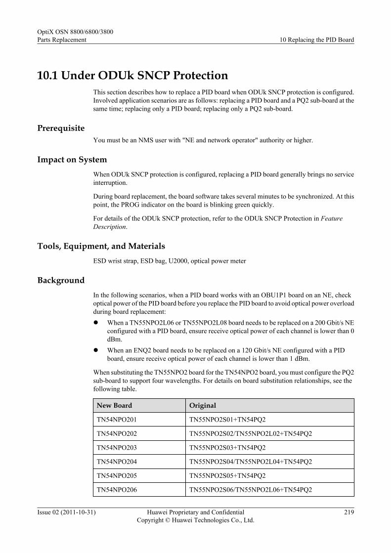
10.1 Under ODUk SNCP ProtectionThis section describes how to replace a PID board when ODUk SNCP protection is configured.Involved application scenarios are as follows: replacing a PID board and a PQ2 sub-board at thesame time; replacing only a PID board; replacing only a PQ2 sub-board.
PrerequisiteYou must be an NMS user with "NE and network operator" authority or higher.
Impact on SystemWhen ODUk SNCP protection is configured, replacing a PID board generally brings no serviceinterruption.
During board replacement, the board software takes several minutes to be synchronized. At thispoint, the PROG indicator on the board is blinking green quickly.
For details of the ODUk SNCP protection, refer to the ODUk SNCP Protection in FeatureDescription.
Tools, Equipment, and MaterialsESD wrist strap, ESD bag, U2000, optical power meter
BackgroundIn the following scenarios, when a PID board works with an OBU1P1 board on an NE, checkoptical power of the PID board before you replace the PID board to avoid optical power overloadduring board replacement:l When a TN55NPO2L06 or TN55NPO2L08 board needs to be replaced on a 200 Gbit/s NE
configured with a PID board, ensure receive optical power of each channel is lower than 0dBm.
l When an ENQ2 board needs to be replaced on a 120 Gbit/s NE configured with a PIDboard, ensure receive optical power of each channel is lower than 1 dBm.
When substituting the TN55NPO2 board for the TN54NPO2 board, you must configure the PQ2sub-board to support four wavelengths. For details on board substitution relationships, see thefollowing table.
New Board Original
TN54NPO201 TN55NPO2S01+TN54PQ2
TN54NPO202 TN55NPO2S02/TN55NPO2L02+TN54PQ2
TN54NPO203 TN55NPO2S03+TN54PQ2
TN54NPO204 TN55NPO2S04/TN55NPO2L04+TN54PQ2
TN54NPO205 TN55NPO2S05+TN54PQ2
TN54NPO206 TN55NPO2S06/TN55NPO2L06+TN54PQ2
OptiX OSN 8800/6800/3800Parts Replacement 10 Replacing the PID Board
Issue 02 (2011-10-31) Huawei Proprietary and ConfidentialCopyright © Huawei Technologies Co., Ltd.
219

New Board Original
TN54NPO207 TN55NPO2S07+TN54PQ2
TN54NPO208 TN55NPO2S08/TN55NPO2L08+TN54PQ2
NOTEWhen you replace the NPO2/NPO2E board and the ENQ2 board at the same time, it is recommended toreplace the NPO2/NPO2E board first.
Precautions
CAUTIONWhen you connect a fiber to the input optical port of an NPO2 or NPO2E board, loosely connectthe fiber to prevent the input optical power from crossing the overload point; otherwise, thereceiver optical module is burnt and damaged.
Procedure (Replacing a PID Board and a PQ2 Sub-board)1. Select a spare board. Ensure the name, version, and software version of the new board are
the same as those of the original board. If the version is inconsistent, you need to determineif the board with different versions can be replaced. For more information on board versions,refer to the Hardware Description.
2. Review and record the current alarms on the NE. For more information, refer to "Queryingthe Current Alarms" of the Supporting Tasks.
NOTE
To replace a board in an upgrade, perform this operation to determine if abnormal alarms are generatedon the NE where the board to be replaced resides and the downstream NE. If there are abnormal alarms,you need to handle these alarms before replacing the board.
3. Test the input optical power. Prevent the input optical power from crossing the overloadpoint; otherwise, the receiver optical module is burnt and damaged. For the procedure, referto the Testing Optical Power by Using an Optical Power Meter in Supporting Tasks.
4. Query the working status of each channel on the board to be replaced.
(1) In the NE Explorer, click the NE and choose Configuration > WDM ServiceManagement from the Function Tree. Click the SNCP Service Control tab.
(2) Click Query to obtain the SNCP protection state of each NE.
OptiX OSN 8800/6800/3800Parts Replacement 10 Replacing the PID Board
Issue 02 (2011-10-31) Huawei Proprietary and ConfidentialCopyright © Huawei Technologies Co., Ltd.
220
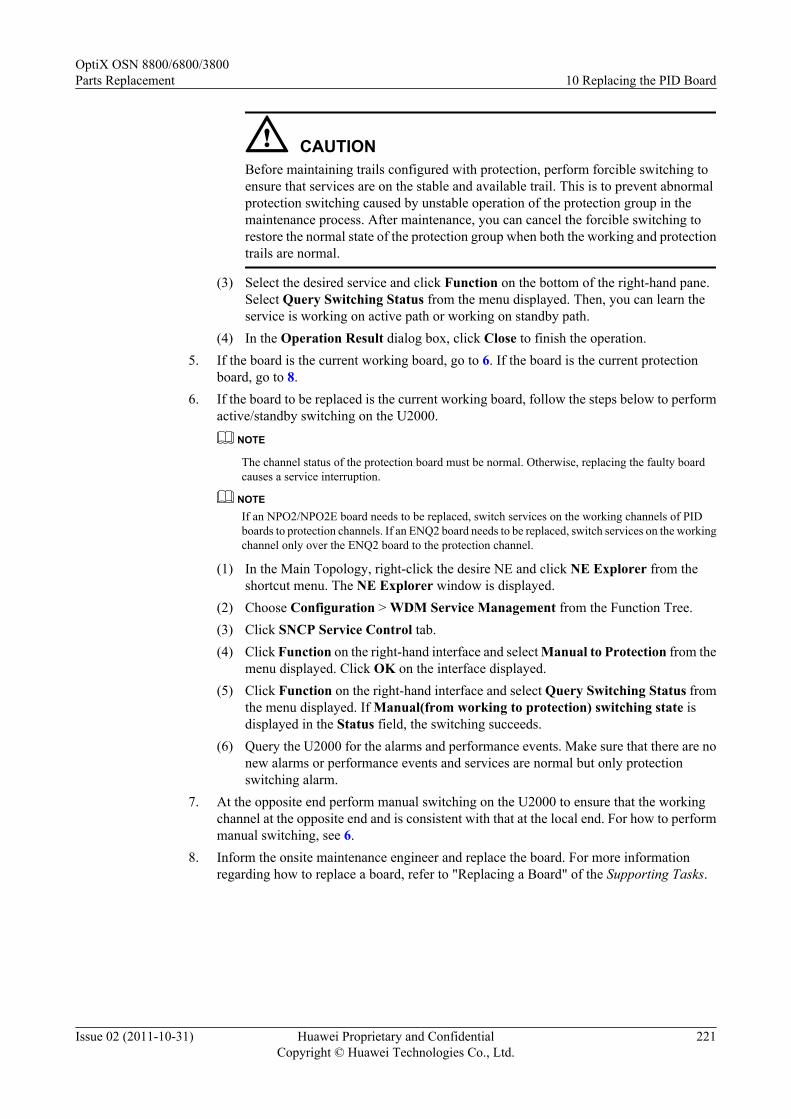
CAUTIONBefore maintaining trails configured with protection, perform forcible switching toensure that services are on the stable and available trail. This is to prevent abnormalprotection switching caused by unstable operation of the protection group in themaintenance process. After maintenance, you can cancel the forcible switching torestore the normal state of the protection group when both the working and protectiontrails are normal.
(3) Select the desired service and click Function on the bottom of the right-hand pane.Select Query Switching Status from the menu displayed. Then, you can learn theservice is working on active path or working on standby path.
(4) In the Operation Result dialog box, click Close to finish the operation.5. If the board is the current working board, go to 6. If the board is the current protection
board, go to 8.6. If the board to be replaced is the current working board, follow the steps below to perform
active/standby switching on the U2000.
NOTE
The channel status of the protection board must be normal. Otherwise, replacing the faulty boardcauses a service interruption.
NOTEIf an NPO2/NPO2E board needs to be replaced, switch services on the working channels of PIDboards to protection channels. If an ENQ2 board needs to be replaced, switch services on the workingchannel only over the ENQ2 board to the protection channel.
(1) In the Main Topology, right-click the desire NE and click NE Explorer from theshortcut menu. The NE Explorer window is displayed.
(2) Choose Configuration > WDM Service Management from the Function Tree.(3) Click SNCP Service Control tab.(4) Click Function on the right-hand interface and select Manual to Protection from the
menu displayed. Click OK on the interface displayed.(5) Click Function on the right-hand interface and select Query Switching Status from
the menu displayed. If Manual(from working to protection) switching state isdisplayed in the Status field, the switching succeeds.
(6) Query the U2000 for the alarms and performance events. Make sure that there are nonew alarms or performance events and services are normal but only protectionswitching alarm.
7. At the opposite end perform manual switching on the U2000 to ensure that the workingchannel at the opposite end and is consistent with that at the local end. For how to performmanual switching, see 6.
8. Inform the onsite maintenance engineer and replace the board. For more informationregarding how to replace a board, refer to "Replacing a Board" of the Supporting Tasks.
OptiX OSN 8800/6800/3800Parts Replacement 10 Replacing the PID Board
Issue 02 (2011-10-31) Huawei Proprietary and ConfidentialCopyright © Huawei Technologies Co., Ltd.
221

NOTE
l Before removing a board, ensure that the fiber jumpers connecting to the optical ports on theboard are removed.
l Before inserting a board, ensure that there is no fiber jumper on the optical ports on the board.
l After the board is replaced, clean the fiber connectors using a fiber cleaning tissue, and restorethe fiber jumpers of the optical ports based on the fiber labels.
l After the board is replaced, the NE software delivers the configuration of the original boardautomatically.
9. Review the indicators of the new board. It takes ten minutes for a new board to worknormally after insertion. Ensure that the STAT indicator of the PID board and the PQ2 sub-board is green. If the indicator gives abnormal indication, you need to reinsert the board,or replace the board again. For more information regarding indicator definitions, refer toIndicators of the Hardware Description.
10. Release the switching on the local and opposite NEs.
(1) In the Main Topology, right-click the desire NE and click NE Explorer from theshortcut menu. The NE Explorer window is displayed.
(2) Choose Configuration > WDM Service Management in the Function Tree.
(3) Click SNCP Service Control tab.
(4) Select the switched service, and click Function on the right-hand interface. SelectClear from the menu displayed.
(5) Click Query, and review Status. If the value is Normal State, the switching succeeds.
11. Query the 15-minute BER before FEC at the receive end of the link. Make sure that theBER before FEC does not deteriorate greatly from the value before board replacement.
(1) Choose Performance > Browse WDM Performance from the Main Menu of theU2000, and then click the Current Performance Data tab.
(2) Choose the desired boards in the left pane, and click the double-right-arrow button(red).
(3) Choose the option from the drop-down list next to Monitored Object FilterCondition.
(4) In Monitor Period, select 15-Minute.
(5) Click Count option button. Select options under Performance Event Type, and selectDisplay Zero Data for the Display Options.
(6) Click Query to query the performance value for bit error on the NE side.
(7) In the Operation Result dialog box, click Close to finish the operation.
(8) In the Monitored Object, FEC_BEF_COR_ER represents the BER before FEC.
12. Query alarms and performances of the local NE and of the opposite NE and confirm thatthe original alarms or performances are cleared.
NOTE
The ENQ2 board does not support the PQ2 sub-board. To replace an ENQ2 board, perform steps 1, 2, 4–10, and 12.
When the Restart Mode of PID IPA is set to Manual, a manual restarting at two stations is required afterthe board is replaced. For more information about restarting of PID IPA, refer to Restarting of PID IPA ofthe Feature Description.
OptiX OSN 8800/6800/3800Parts Replacement 10 Replacing the PID Board
Issue 02 (2011-10-31) Huawei Proprietary and ConfidentialCopyright © Huawei Technologies Co., Ltd.
222

Procedure (Replacing Only a PID Board)1. Select a spare board. Ensure the name, version, and software version of the new board are
the same as those of the original board. If the version is inconsistent, you need to determineif the board with different versions can be replaced. For more information on board versions,refer to the Hardware Description.
2. Review and record the current alarms on the NE. For more information, refer to "Queryingthe Current Alarms" of the Supporting Tasks.
NOTE
To replace a board in an upgrade, perform this operation to determine if abnormal alarms are generatedon the NE where the board to be replaced resides and the downstream NE. If there are abnormal alarms,you need to handle these alarms before replacing the board.
3. Test the input optical power. Prevent the input optical power from crossing the overloadpoint; otherwise, the receiver optical module is burnt and damaged. For the procedure, referto the Testing Optical Power by Using an Optical Power Meter in Supporting Tasks.
4. Query the working status of each channel on the board to be replaced.
(1) In the NE Explorer, click the NE and choose Configuration > WDM ServiceManagement from the Function Tree. Click the SNCP Service Control tab.
(2) Click Query to obtain the SNCP protection state of each NE.
CAUTIONBefore maintaining trails configured with protection, perform forcible switching toensure that services are on the stable and available trail. This is to prevent abnormalprotection switching caused by unstable operation of the protection group in themaintenance process. After maintenance, you can cancel the forcible switching torestore the normal state of the protection group when both the working and protectiontrails are normal.
(3) Select the desired service and click Function on the bottom of the right-hand pane.Select Query Switching Status from the menu displayed. Then, you can learn theservice is working on active path or working on standby path.
(4) In the Operation Result dialog box, click Close to finish the operation.5. If the board is the current working board, go to 6. If the board is the current protection
board, go to 8.6. If the board to be replaced is the current working board, follow the steps below to perform
active/standby switching on the U2000.
NOTE
The channel status of the protection board must be normal. Otherwise, replacing the faulty boardcauses a service interruption.
NOTEIf an NPO2/NPO2E board needs to be replaced, switch services on the working channels of PIDboards to protection channels. If an ENQ2 board needs to be replaced, switch services on the workingchannel only over the ENQ2 board to the protection channel.
(1) In the Main Topology, right-click the desire NE and click NE Explorer from theshortcut menu. The NE Explorer window is displayed.
(2) Choose Configuration > WDM Service Management from the Function Tree.
OptiX OSN 8800/6800/3800Parts Replacement 10 Replacing the PID Board
Issue 02 (2011-10-31) Huawei Proprietary and ConfidentialCopyright © Huawei Technologies Co., Ltd.
223

(3) Click SNCP Service Control tab.(4) Click Function on the right-hand interface and select Manual to Protection from the
menu displayed. Click OK on the interface displayed.(5) Click Function on the right-hand interface and select Query Switching Status from
the menu displayed. If Manual(from working to protection) switching state isdisplayed in the Status field, the switching succeeds.
(6) Query the U2000 for the alarms and performance events. Make sure that there are nonew alarms or performance events and services are normal but only protectionswitching alarm.
7. At the opposite end perform manual switching on the U2000 to ensure that the workingchannel at the opposite end and is consistent with that at the local end. For how to performmanual switching, see 6.
8. Inform the onsite maintenance engineer and replace the board.
(1) Remove the pigtail connected to the optical port and remove the board to be replaced.(2) Loosen the screws on the PQ2 sub-board and remove the board.(3) Install the PQ2 sub-board on the new board and tighten the screws on the PQ2 sub-
board.(4) Insert the new board to the original slot. For details on how to remove and insert a
new board, see "Replacing a Board" of the Supporting Tasks.(5) After board replacement is complete, clean the fiber connector using a fiber cleaning
tissue and reconnect the pigtail to the optical port based on the fiber labels.
NOTEAfter the board is replaced, the NE software delivers the configuration of the original boardautomatically.
9. Review the indicators of the new board. It takes ten minutes for a new board to worknormally after insertion. Ensure that the STAT indicator of the PID board and the sub-boardis green. If the indicator gives abnormal indication, you need to reinsert the board, or replacethe board again. For more information regarding indicator definitions, refer to Indicatorsof the Hardware Description.
10. Release the switching on the local and opposite NEs.
(1) In the Main Topology, right-click the desire NE and click NE Explorer from theshortcut menu. The NE Explorer window is displayed.
(2) Choose Configuration > WDM Service Management in the Function Tree.(3) Click SNCP Service Control tab.(4) Select the switched service, and click Function on the right-hand interface. Select
Clear from the menu displayed.(5) Click Query, and review Status. If the value is Normal State, the switching succeeds.
11. Query the 15-minute BER before FEC at the receive end of the link. Make sure that theBER before FEC does not deteriorate greatly from the value before board replacement.
(1) Choose Performance > Browse WDM Performance from the Main Menu of theU2000, and then click the Current Performance Data tab.
(2) Choose the desired boards in the left pane, and click the double-right-arrow button(red).
(3) Choose the option from the drop-down list next to Monitored Object FilterCondition.
OptiX OSN 8800/6800/3800Parts Replacement 10 Replacing the PID Board
Issue 02 (2011-10-31) Huawei Proprietary and ConfidentialCopyright © Huawei Technologies Co., Ltd.
224

(4) In Monitor Period, select 15-Minute.
(5) Click Count option button. Select options under Performance Event Type, and selectDisplay Zero Data for the Display Options.
(6) Click Query to query the performance value for bit error on the NE side.
(7) In the Operation Result dialog box, click Close to finish the operation.
(8) In the Monitored Object, FEC_BEF_COR_ER represents the BER before FEC.
12. Query alarms and performances of the local NE and of the opposite NE and confirm thatthe original alarms or performances are cleared.
NOTE
When the Restart Mode of PID IPA is set to Manual, a manual restarting at two stations is required afterthe board is replaced. For more information about restarting of PID IPA, refer to Restarting of PID IPA ofthe Feature Description.
Procedure (Replacing Only a PQ2 Sub-board)1. Review and record the current alarms on the NE. For more information, refer to "Querying
the Current Alarms" of the Supporting Tasks.
NOTE
To replace a board in an upgrade, perform this operation to determine if abnormal alarms are generatedon the NE where the board to be replaced resides and the downstream NE. If there are abnormal alarms,you need to handle these alarms before replacing the board.
2. Query the working status of the NPO2/NPO2E board where the PQ2 sub-board resides.
(1) In the NE Explorer, click the NE and choose Configuration > WDM ServiceManagement from the Function Tree. Click the SNCP Service Control tab.
(2) Click Query to obtain the SNCP protection state of each NE.
CAUTIONBefore maintaining trails configured with protection, perform forcible switching toensure that services are on the stable and available trail. This is to prevent abnormalprotection switching caused by unstable operation of the protection group in themaintenance process. After maintenance, you can cancel the forcible switching torestore the normal state of the protection group when both the working and protectiontrails are normal.
(3) Select the desired service and click Function on the bottom of the right-hand pane.Select Query Switching Status from the menu displayed. Then, you can learn theservice is working on active path or working on standby path.
(4) In the Operation Result dialog box, click Close to finish the operation.
3. If the board is the working NPO2 or NPO2E board, go to 4. If the board is the protectionNPO2 or NPO2E board, go to 6.
4. If the NPO2/NPO2E board where the PQ2 sub-board to be replaced resides is the workingboard, perform manual switching on the NPO2/NPO2E board in U2000.
NOTEIn this step, you need to switch services on all working channels of PID boards to protection channels.
OptiX OSN 8800/6800/3800Parts Replacement 10 Replacing the PID Board
Issue 02 (2011-10-31) Huawei Proprietary and ConfidentialCopyright © Huawei Technologies Co., Ltd.
225

NOTE
The channel status of the protection board must be normal. Otherwise, replacing the faulty boardcauses a service interruption.
(1) In the Main Topology, right-click the desire NE and click NE Explorer from theshortcut menu. The NE Explorer window is displayed.
(2) Choose Configuration > WDM Service Management from the Function Tree.(3) Click SNCP Service Control tab.(4) Click Function on the right-hand interface and select Manual to Protection from the
menu displayed. Click OK on the interface displayed.(5) Click Function on the right-hand interface and select Query Switching Status from
the menu displayed. If Manual(from working to protection) switching state isdisplayed in the Status field, the switching succeeds.
(6) Query the U2000 for the alarms and performance events. Make sure that there are nonew alarms or performance events and services are normal but only protectionswitching alarm.
5. At the opposite end perform manual switching on the U2000 to ensure that the workingchannel at the opposite end and is consistent with that at the local end. For how to performmanual switching, see 4.
6. Inform the onsite maintenance engineer and replace the PQ2 sub-board.
(1) Loosen the screws on the PQ2 sub-board and remove the board.(2) Install the new PQ2 sub-board on the original board and tighten the screws on the PQ2
sub-board.7. Review the indicators of the new board. It takes three minutes for a new board to work
normally after insertion. Ensure that the STAT indicator of the PQ2 sub-board is green. Ifthe indicator gives abnormal indication, you need to reinsert the board, or replace the boardagain. For more information regarding indicator definitions, refer to Indicators of theHardware Description.
8. Release the switching on the local and opposite NEs.
(1) In the Main Topology, right-click the desire NE and click NE Explorer from theshortcut menu. The NE Explorer window is displayed.
(2) Choose Configuration > WDM Service Management in the Function Tree.(3) Click SNCP Service Control tab.(4) Select the switched service, and click Function on the right-hand interface. Select
Clear from the menu displayed.(5) Click Query, and review Status. If the value is Normal State, the switching succeeds.
9. Query alarms and performances of the local NE and of the opposite NE and confirm thatthe original alarms or performances are cleared.
NOTE
When the Restart Mode of PID IPA is set to Manual, a manual restarting at two stations is required afterthe board is replaced. For more information about restarting of PID IPA, refer to Restarting of PID IPA ofthe Feature Description.
OptiX OSN 8800/6800/3800Parts Replacement 10 Replacing the PID Board
Issue 02 (2011-10-31) Huawei Proprietary and ConfidentialCopyright © Huawei Technologies Co., Ltd.
226

10.2 Under No ProtectionThis section describes how to replace a PID board when no protection is configured. Involvedapplication scenarios are as follows: replacing a PID board and a PQ2 sub-board at the sametime; replacing only a PID board; replacing only a PQ2 sub-board.
PrerequisiteYou must be an NMS user with "NE and network operator" authority or higher.
Impact on System
Replacing a PID board without protection will interrupt services. Replacing only a PQ2 sub-board will interrupt channels 5 to 8 on the NPO2 or NPO2E board.
During board replacement, the board software takes several minutes to be synchronized. At thispoint, the PROG indicator on the board is blinking green quickly.
Tools, Equipment, and Materials
ESD wrist strap, ESD bag, U2000, optical power meter
Background
In the following scenarios, when a PID board works with an OBU1P1 board on an NE, checkoptical power of the PID board before you replace the PID board to avoid optical power overloadduring board replacement:
l When a TN55NPO2L06 or TN55NPO2L08 board needs to be replaced on a 200 Gbit/s NEconfigured with a PID board, ensure receive optical power of each channel is lower than 0dBm.
l When an ENQ2 board needs to be replaced on a 120 Gbit/s NE configured with a PIDboard, ensure receive optical power of each channel is lower than 1 dBm.
When substituting the TN55NPO2 board for the TN54NPO2 board, you must configure the PQ2sub-board to support four wavelengths. For details on board substitution relationships, see thefollowing table.
New Board Original
TN54NPO201 TN55NPO2S01+TN54PQ2
TN54NPO202 TN55NPO2S02/TN55NPO2L02+TN54PQ2
TN54NPO203 TN55NPO2S03+TN54PQ2
TN54NPO204 TN55NPO2S04/TN55NPO2L04+TN54PQ2
TN54NPO205 TN55NPO2S05+TN54PQ2
TN54NPO206 TN55NPO2S06/TN55NPO2L06+TN54PQ2
TN54NPO207 TN55NPO2S07+TN54PQ2
OptiX OSN 8800/6800/3800Parts Replacement 10 Replacing the PID Board
Issue 02 (2011-10-31) Huawei Proprietary and ConfidentialCopyright © Huawei Technologies Co., Ltd.
227
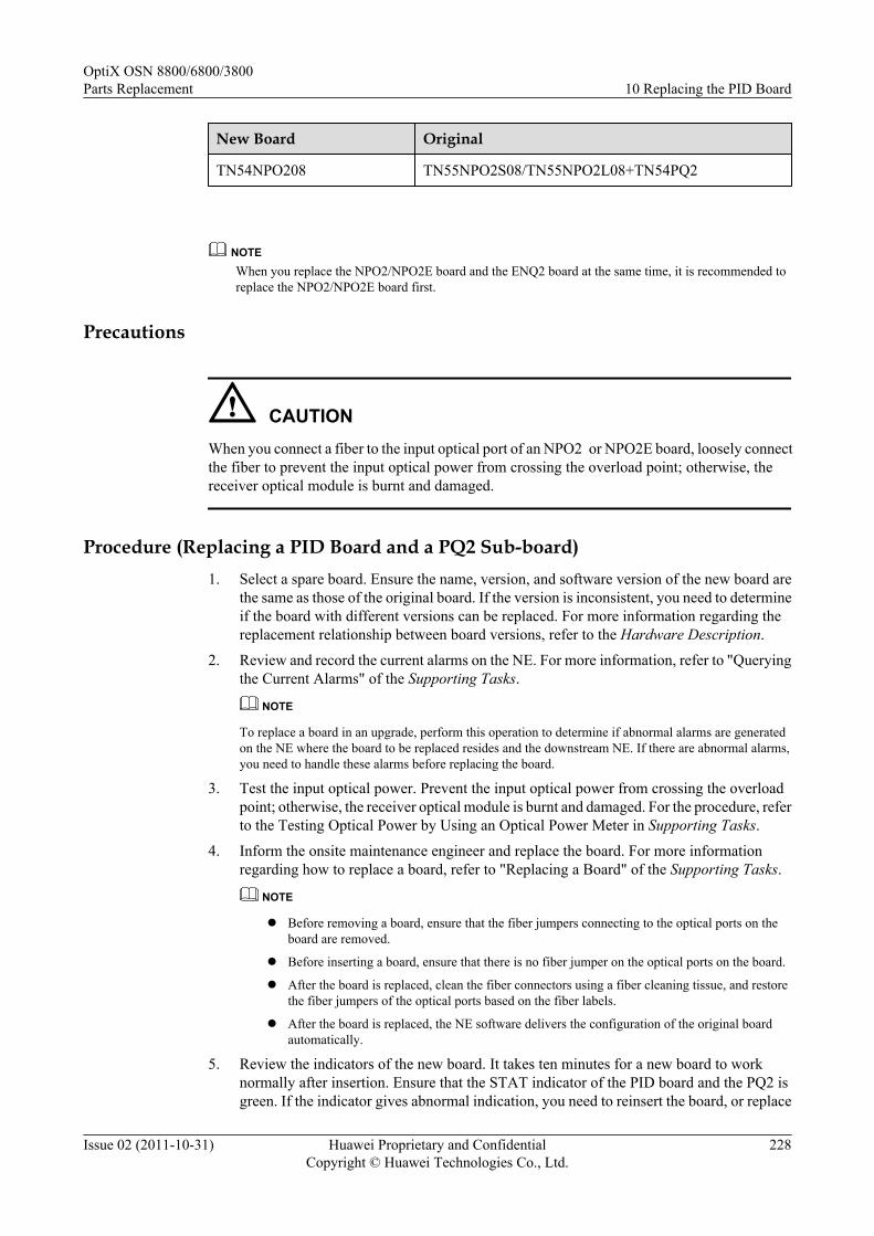
New Board Original
TN54NPO208 TN55NPO2S08/TN55NPO2L08+TN54PQ2
NOTEWhen you replace the NPO2/NPO2E board and the ENQ2 board at the same time, it is recommended toreplace the NPO2/NPO2E board first.
Precautions
CAUTIONWhen you connect a fiber to the input optical port of an NPO2 or NPO2E board, loosely connectthe fiber to prevent the input optical power from crossing the overload point; otherwise, thereceiver optical module is burnt and damaged.
Procedure (Replacing a PID Board and a PQ2 Sub-board)1. Select a spare board. Ensure the name, version, and software version of the new board are
the same as those of the original board. If the version is inconsistent, you need to determineif the board with different versions can be replaced. For more information regarding thereplacement relationship between board versions, refer to the Hardware Description.
2. Review and record the current alarms on the NE. For more information, refer to "Queryingthe Current Alarms" of the Supporting Tasks.
NOTE
To replace a board in an upgrade, perform this operation to determine if abnormal alarms are generatedon the NE where the board to be replaced resides and the downstream NE. If there are abnormal alarms,you need to handle these alarms before replacing the board.
3. Test the input optical power. Prevent the input optical power from crossing the overloadpoint; otherwise, the receiver optical module is burnt and damaged. For the procedure, referto the Testing Optical Power by Using an Optical Power Meter in Supporting Tasks.
4. Inform the onsite maintenance engineer and replace the board. For more informationregarding how to replace a board, refer to "Replacing a Board" of the Supporting Tasks.
NOTE
l Before removing a board, ensure that the fiber jumpers connecting to the optical ports on theboard are removed.
l Before inserting a board, ensure that there is no fiber jumper on the optical ports on the board.
l After the board is replaced, clean the fiber connectors using a fiber cleaning tissue, and restorethe fiber jumpers of the optical ports based on the fiber labels.
l After the board is replaced, the NE software delivers the configuration of the original boardautomatically.
5. Review the indicators of the new board. It takes ten minutes for a new board to worknormally after insertion. Ensure that the STAT indicator of the PID board and the PQ2 isgreen. If the indicator gives abnormal indication, you need to reinsert the board, or replace
OptiX OSN 8800/6800/3800Parts Replacement 10 Replacing the PID Board
Issue 02 (2011-10-31) Huawei Proprietary and ConfidentialCopyright © Huawei Technologies Co., Ltd.
228

the board again. For more information regarding indicator definitions, refer to Indicatorsof the Hardware Description.
6. Query the 15-minute BER before FEC at the receive end of the link. Make sure that theBER before FEC does not deteriorate greatly from the value before board replacement.
(1) Choose Performance > Browse WDM Performance from the Main Menu of theU2000, and then click the Current Performance Data tab.
(2) Choose the desired boards in the left pane, and click the double-right-arrow button(red).
(3) Choose the option from the drop-down list next to Monitored Object FilterCondition.
(4) In Monitor Period, select 15-Minute.
(5) Click Count option button. Select options under Performance Event Type, and selectDisplay Zero Data for the Display Options.
(6) Click Query to query the performance value for bit error on the NE side.
(7) In the Operation Result dialog box, click Close to finish the operation.
(8) In the Monitored Object, FEC_BEF_COR_ER represents the BER before FEC.
7. Query alarms and performances of the local NE and of the opposite NE and confirm thatthe original alarms or performances are cleared.
NOTE
The ENQ2 board does not support the PQ2 sub-board. To replace an ENQ2 board, perform steps 1, 2, 4,5 and 7.
When the Restart Mode of PID IPA is set to Manual, a manual restarting at two stations is required afterthe board is replaced. For more information about restarting of PID IPA, refer to Restarting of PID IPA ofthe Feature Description.
Procedure (Replacing Only a PID Board)1. Select a spare board. Ensure the name, version, and software version of the new board are
the same as those of the original board. If the version is inconsistent, you need to determineif the board with different versions can be replaced. For more information regarding thereplacement relationship between board versions, refer to the Hardware Description.
2. Review and record the current alarms on the NE. For more information, refer to "Queryingthe Current Alarms" of the Supporting Tasks.
NOTE
To replace a board in an upgrade, perform this operation to determine if abnormal alarms are generatedon the NE where the board to be replaced resides and the downstream NE. If there are abnormal alarms,you need to handle these alarms before replacing the board.
3. Test the input optical power. Prevent the input optical power from crossing the overloadpoint; otherwise, the receiver optical module is burnt and damaged. For the procedure, referto the Testing Optical Power by Using an Optical Power Meter in Supporting Tasks.
4. Inform the onsite maintenance engineer and replace the board.
(1) Remove the pigtail connected to the optical port and remove the board to be replaced.
(2) Loosen the screws on the PQ2 sub-board and remove the board.
(3) Install the PQ2 sub-board on the new board and tighten the screws on the PQ2 sub-board.
OptiX OSN 8800/6800/3800Parts Replacement 10 Replacing the PID Board
Issue 02 (2011-10-31) Huawei Proprietary and ConfidentialCopyright © Huawei Technologies Co., Ltd.
229

(4) Insert the new board to the original slot. For details on how to remove and insert anew board, see "Replacing a Board" of the Supporting Tasks.
(5) After board replacement is complete, clean the fiber connector using a fiber cleaningtissue and reconnect the pigtail to the optical port based on the fiber labels.
NOTEAfter the board is replaced, the NE software delivers the configuration of the original boardautomatically.
5. Review the indicators of the new board. It takes ten minutes for a new board to worknormally after insertion. Ensure that the STAT indicator of the PID board and the PQ2 sub-board is green. If the indicator gives abnormal indication, you need to reinsert the board,or replace the board again. For more information regarding indicator definitions, refer toIndicators of the Hardware Description.
6. Query the 15-minute BER before FEC at the receive end of the link. Make sure that theBER before FEC does not deteriorate greatly from the value before board replacement.
(1) Choose Performance > Browse WDM Performance from the Main Menu of theU2000, and then click the Current Performance Data tab.
(2) Choose the desired boards in the left pane, and click the double-right-arrow button(red).
(3) Choose the option from the drop-down list next to Monitored Object FilterCondition.
(4) In Monitor Period, select 15-Minute.(5) Click Count option button. Select options under Performance Event Type, and select
Display Zero Data for the Display Options.(6) Click Query to query the performance value for bit error on the NE side.(7) In the Operation Result dialog box, click Close to finish the operation.(8) In the Monitored Object, FEC_BEF_COR_ER represents the BER before FEC.
7. Query alarms and performances of the local NE and of the opposite NE and confirm thatthe original alarms or performances are cleared.
NOTE
When the Restart Mode of PID IPA is set to Manual, a manual restarting at two stations is required afterthe board is replaced. For more information about restarting of PID IPA, refer to Restarting of PID IPA ofthe Feature Description.
Procedure (Replacing Only a PQ2 Sub-board)1. Review and record the current alarms on the NE. For more information, refer to "Querying
the Current Alarms" of the Supporting Tasks.NOTE
To replace a board in an upgrade, perform this operation to determine if abnormal alarms are generatedon the NE where the board to be replaced resides and the downstream NE. If there are abnormal alarms,you need to handle these alarms before replacing the board.
2. Inform the onsite maintenance engineer and replace the PQ2 sub-board.
(1) Loosen the screws on the PQ2 sub-board and remove the board.(2) Install the new PQ2 sub-board on the original board and tighten the screws on the PQ2
sub-board.3. Review the indicators of the new board. It takes three minutes for a new board to work
normally after insertion. Ensure that the STAT indicator of the PQ2 sub-board is green. If
OptiX OSN 8800/6800/3800Parts Replacement 10 Replacing the PID Board
Issue 02 (2011-10-31) Huawei Proprietary and ConfidentialCopyright © Huawei Technologies Co., Ltd.
230

the indicator gives abnormal indication, you need to reinsert the board, or replace the boardagain. For more information regarding indicator definitions, refer to Indicators of theHardware Description.
4. Query alarms and performances of the local NE and of the opposite NE and confirm thatthe original alarms or performances are cleared.
NOTE
When the Restart Mode of PID IPA is set to Manual, a manual restarting at two stations is required afterthe board is replaced. For more information about restarting of PID IPA, refer to Restarting of PID IPA ofthe Feature Description.
OptiX OSN 8800/6800/3800Parts Replacement 10 Replacing the PID Board
Issue 02 (2011-10-31) Huawei Proprietary and ConfidentialCopyright © Huawei Technologies Co., Ltd.
231
11 Replacing the SDH Board
About This Chapter
This section describes how to replace the SDH board.
The SDH board can be replaced when:
l Protection is configured.l There is no protection for the SDH board.
11.1 Under ProtectionThis section describes how to replace an SDH board when protection is configured for the SDHboard.
11.2 Under No ProtectionThis section describes how to replace an SDH board when no protection is configured for theSDH board.
OptiX OSN 8800/6800/3800Parts Replacement 11 Replacing the SDH Board
Issue 02 (2011-10-31) Huawei Proprietary and ConfidentialCopyright © Huawei Technologies Co., Ltd.
232
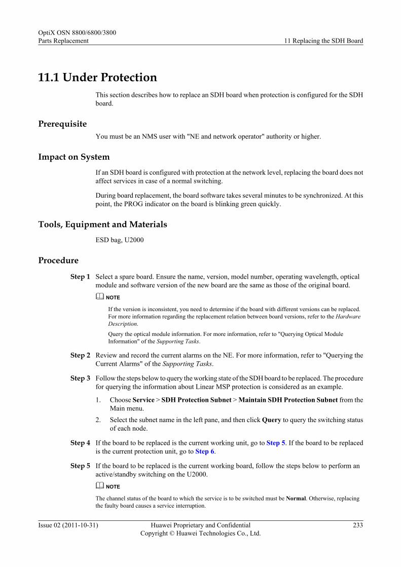
11.1 Under ProtectionThis section describes how to replace an SDH board when protection is configured for the SDHboard.
PrerequisiteYou must be an NMS user with "NE and network operator" authority or higher.
Impact on System
If an SDH board is configured with protection at the network level, replacing the board does notaffect services in case of a normal switching.
During board replacement, the board software takes several minutes to be synchronized. At thispoint, the PROG indicator on the board is blinking green quickly.
Tools, Equipment and Materials
ESD bag, U2000
Procedure
Step 1 Select a spare board. Ensure the name, version, model number, operating wavelength, opticalmodule and software version of the new board are the same as those of the original board.
NOTE
If the version is inconsistent, you need to determine if the board with different versions can be replaced.For more information regarding the replacement relation between board versions, refer to the HardwareDescription.
Query the optical module information. For more information, refer to "Querying Optical ModuleInformation" of the Supporting Tasks.
Step 2 Review and record the current alarms on the NE. For more information, refer to "Querying theCurrent Alarms" of the Supporting Tasks.
Step 3 Follow the steps below to query the working state of the SDH board to be replaced. The procedurefor querying the information about Linear MSP protection is considered as an example.
1. Choose Service > SDH Protection Subnet > Maintain SDH Protection Subnet from theMain menu.
2. Select the subnet name in the left pane, and then click Query to query the switching statusof each node.
Step 4 If the board to be replaced is the current working unit, go to Step 5. If the board to be replacedis the current protection unit, go to Step 6.
Step 5 If the board to be replaced is the current working board, follow the steps below to perform anactive/standby switching on the U2000.
NOTE
The channel status of the board to which the service is to be switched must be Normal. Otherwise, replacingthe faulty board causes a service interruption.
OptiX OSN 8800/6800/3800Parts Replacement 11 Replacing the SDH Board
Issue 02 (2011-10-31) Huawei Proprietary and ConfidentialCopyright © Huawei Technologies Co., Ltd.
233

1. In the Main Topology, right-click the desire NE and click NE Explorer from the shortcutmenu. The NE Explorer window is displayed.
2. Choose Configuration > Linear MS from the Function Tree.3. Select a channel in Slot Mapping Settings, and choose Exercise Switching from the
shortcut menu. In the displayed dialog box, click Close.4. Click Query > Query Switching Status. If Exercise Switching is displayed in West
Switching Status, it indicates that the exercise Linear MSP switching is in process.5. Query the alarms and performance events on the U2000. If only the alarms and performance
events relevant to the exercise switching occur (that is, no other alarms or performanceevents occur) and the services are normal, it indicates that the switching is successful.
6. In Slot Mapping Settings, select the channel. Then, choose Manual to Protection fromthe shortcut menu. In the Operation Result dialog box that is displayed, click Close.
7. Click Query > Query Switching Status. If Manual Switching is displayed in WestSwitching Status, it indicates that the manual Linear MSP switching is in process.
Step 6 Inform the onsite maintenance engineer and replace the board. For details on how to replace aboard, see "Replacing a Board" of the Supporting Tasks.
Step 7 Review the indicators of the new board. It takes ten minutes for a new board to work normallyafter insertion. Ensure that the STAT indicator is steady green. If the indicator gives abnormalindication, you need to reinsert the board, or replace the board again. For more informationregarding indicator definitions, refer to "Indicators" of the Hardware Description.
Step 8 Query alarms and performances of the local NE and of the opposite NE and confirm that theoriginal alarms or performances are cleared.
Step 9 Optional: Follow the steps below to cancel the switching.
1. In the Main Topology, right-click the desire NE and click NE Explorer from the shortcutmenu. The NE Explorer window is displayed.
2. Choose Configuration > Linear MS from the Function Tree.3. Select a channel in Slot Mapping Settingsship, and choose Clear from the shortcut menu.
In the displayed dialog box, click Close.4. Click Query > Query Switching Status. If Normal is displayed in the node switching
status field, it indicates that the switching is cleared.
Step 10 Query alarms and performances of the local NE and of the opposite NE and confirm that theoriginal alarms or performances are cleared.
----End
11.2 Under No ProtectionThis section describes how to replace an SDH board when no protection is configured for theSDH board.
PrerequisiteYou must be an NMS user with "NE and network operator" authority or higher.
Impact on SystemReplacing unprotected SDH boards brings a service interruption.
OptiX OSN 8800/6800/3800Parts Replacement 11 Replacing the SDH Board
Issue 02 (2011-10-31) Huawei Proprietary and ConfidentialCopyright © Huawei Technologies Co., Ltd.
234
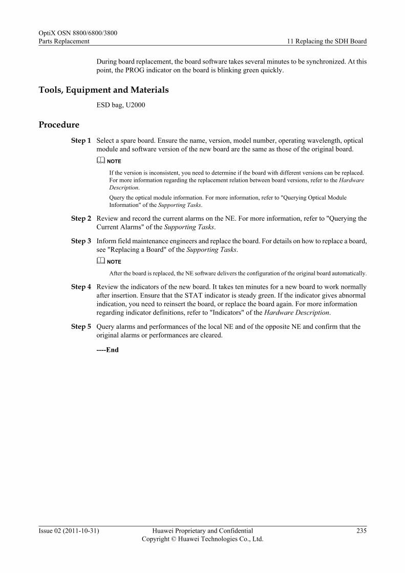
During board replacement, the board software takes several minutes to be synchronized. At thispoint, the PROG indicator on the board is blinking green quickly.
Tools, Equipment and MaterialsESD bag, U2000
Procedure
Step 1 Select a spare board. Ensure the name, version, model number, operating wavelength, opticalmodule and software version of the new board are the same as those of the original board.
NOTE
If the version is inconsistent, you need to determine if the board with different versions can be replaced.For more information regarding the replacement relation between board versions, refer to the HardwareDescription.
Query the optical module information. For more information, refer to "Querying Optical ModuleInformation" of the Supporting Tasks.
Step 2 Review and record the current alarms on the NE. For more information, refer to "Querying theCurrent Alarms" of the Supporting Tasks.
Step 3 Inform field maintenance engineers and replace the board. For details on how to replace a board,see "Replacing a Board" of the Supporting Tasks.
NOTE
After the board is replaced, the NE software delivers the configuration of the original board automatically.
Step 4 Review the indicators of the new board. It takes ten minutes for a new board to work normallyafter insertion. Ensure that the STAT indicator is steady green. If the indicator gives abnormalindication, you need to reinsert the board, or replace the board again. For more informationregarding indicator definitions, refer to "Indicators" of the Hardware Description.
Step 5 Query alarms and performances of the local NE and of the opposite NE and confirm that theoriginal alarms or performances are cleared.
----End
OptiX OSN 8800/6800/3800Parts Replacement 11 Replacing the SDH Board
Issue 02 (2011-10-31) Huawei Proprietary and ConfidentialCopyright © Huawei Technologies Co., Ltd.
235

12 Replacing the BPA Board
This section describes how to replace the BPA board.
PrerequisiteYou must be an NMS user with "NE and network operator" authority or higher.
Impact on SystemIf the board is not configured with protection, the services are interrupted or signals are degradedwhen you replace the board.
During board replacement, the board software takes several minutes to be synchronized. At thispoint, the PROG indicator on the board is blinking green quickly.
Tools, Equipment and MaterialsESD bag, U2000
Procedure
Step 1 Select a spare board. Ensure the name, version and model number of the new board are the sameas those of the original board.
NOTE
If the version is inconsistent, you need to determine if the board with different versions can be replaced.For more information regarding the replacement relation between board versions, refer to the HardwareDescription.
Step 2 Review and record the current alarms on the NE. For more information, refer to "Querying theCurrent Alarms" of the Supporting Tasks.
Step 3 Query the protection configuration of the network. Query whether the equipment is configuredwith protection by using the U2000. If the equipment is not configured with protection, go toStep 5. The following example describes how to query the MSP protection.
1. Choose Service > SDH Protection Subnet > Maintain SDH Protection Subnet from theMain menu.
2. Select the subnet name in the left pane, and then click Query to query the switching statusof each node.
OptiX OSN 8800/6800/3800Parts Replacement 12 Replacing the BPA Board
Issue 02 (2011-10-31) Huawei Proprietary and ConfidentialCopyright © Huawei Technologies Co., Ltd.
236

Step 4 Start the network switching on the U2000 if the switching is not performed. The followingexample describes how to start the MSP protection switching.
1. In the Main Topology, right-click the desire NE and click NE Explorer from the shortcutmenu. The NE Explorer window is displayed.
2. Choose Configuration > Ring MS from the Function Tree.3. Right-click the board to be replaced and choose Exercise-Ring from the shortcut menu. In
the Operation Result dialog box that is displayed, click Close.4. Choose Query > Query Switching Status. If the switching status of the node is displayed
as Exercise-Ring, the MSP switching is normal.5. Query the alarms and performance events on the U2000, and check whether there are any
new alarms and performance events besides the alarms (such as APS_INDI) generated inthe exercise switching. If there are no new alarms and performance events and the servicesare normal, the switching is successful.
6. Select the board to be replaced and choose Forced Switching to Protection-Ring fromthe shortcut menu. In the Operation Result dialog box that is displayed, click Close.
7. Click Query > Query Switching Status. If the switching status of the node is displayedas Forced Switching-ring, the MSP switching is normal.
NOTE
When you perform the forced switching to protection-ring, the APS_INDI alarm is reported.
Step 5 Inform the onsite maintenance engineer and replace the board. For more information regardinghow to replace a board, refer to "Replacing a Board" of the Supporting Tasks.
OptiX OSN 8800/6800/3800Parts Replacement 12 Replacing the BPA Board
Issue 02 (2011-10-31) Huawei Proprietary and ConfidentialCopyright © Huawei Technologies Co., Ltd.
237

NOTE
l If the software version of the spare board is V100R004C01 or earlier, perform the following operationsbefore replacing the board:
l If the board is installed in the OptiX OSN 3800 subrack, no operation is required.
l If the OptiX OSN 8800 T64 functions as the master subrack, you need to take the following actionson the replacement board before replacing any original board on the NE. Otherwise, the services of theactive boards in other slots may be interrupted.
l a. Install the spare board to any available slot of the OptiX OSN 6800 subrack of versionV100R004C02 or later. Note that the master subrack of the NE where the OptiX OSN 6800 subrackis located cannot be OptiX OSN 8800 T64. For more information regarding the valid slots of theboard, see "Valid Slots" in the Hardware Description.
l b. When the replacement board is in service, review the indicators on the board. If any indicatorflashes abnormally, reset or replace the replacement board. For description of the indicators, see"Indicator" in the Hardware Description.
l c. Double-click the icon of the optical NE in the Physical View, and the NE Panel is displayed.Click the NE where the replacement board resides.
l d. Right-click the slot where the replacement board resides. Choose Add Physical Board from theshortcut menu.
l e. Right-click the slot where the replacement board resides. Choose Version from the shortcutmenu to query the board software version information, and record the displayed versioninformation.
l f. Right click the slot where the replacement board resides. Choose Delete from the shortcut menu.
l g. Right-click the slot where the board to be replaced or the board with the same type as the boardto be replaced resides. Choose Version from the shortcut menu. If the version is the same as thatrecorded in Step e, it indicates that the process of the replacement board is successful. Otherwise,reset or replace the replacement board, and repeat Steps a to g.
l h. Remove the replacement board, and the process of the replacement board is complete.
l i. Replace the fault board. For more information, refer to "Replacing a Board" of the SupportingTasks.
l If the OptiX OSN 8800 T64 does not function as the master subrack, and the board to be replaced isin any slot of the OptiX OSN 8800 T32 or OptiX OSN 8800 T64 subrack on the NE, you need toperform the following operations on the replacement board before replacing the original board.Otherwise, the services of the active boards in other slots may be interrupted. If the board is installedin the OptiX OSN 6800 subrack, no operation is required.
l a. Install the spare board in any available slot of the OptiX OSN 6800 subrack of versionV100R004C02 or later. For more information regarding the valid slots of the board, see "ValidSlots" in the Hardware Description.
l b. For other operations, see the previous steps b to i.
NOTE
l Before removing a board, ensure that the fiber jumpers connecting to the optical interfaces on the board areremoved.
l Before inserting a board, ensure that there are no fiber jumpers on the optical interfaces on the board.
l After the board is replaced, clean the fiber connectors using a fiber cleaning tissue, and restore the fiberjumpers of the optical interfaces based on the fiber labels.
l After the board is replaced, the NE software delivers the configuration of the original board automatically.
Step 6 Clear the MSP switching by using the U2000.
1. In the Main Topology, right-click the desire NE and click NE Explorer from the shortcutmenu. The NE Explorer window is displayed.
2. Choose Configuration > Ring MS from the Function Tree.
OptiX OSN 8800/6800/3800Parts Replacement 12 Replacing the BPA Board
Issue 02 (2011-10-31) Huawei Proprietary and ConfidentialCopyright © Huawei Technologies Co., Ltd.
238

3. Check whether the board works normally. Check the STAT indicator on the board. If theindicator is on and green, the board works normally.
4. Right-click the replaced board and choose Clear All from the shortcut menu. In theOperation Result dialog box that is displayed, click Close.
5. Click Query > Query Switching Status. If the switching status of the node is displayedas Normal, the MSP switching is cleared.
Step 7 View the indicators on the front panel of the new board. It takes approximately three or fourminutes for a new board to work normally after insertion. Ensure that the STAT indicator isgreen and blinks once every other second. If the indicator is not steady on green, you need toreinsert the board or select a new replacement board. For details about the indicators, see"Indicators" of the Hardware Description.
Step 8 Query alarms and performances of the local NE and of the opposite NE and confirm that theoriginal alarms or performances are cleared.
----End
OptiX OSN 8800/6800/3800Parts Replacement 12 Replacing the BPA Board
Issue 02 (2011-10-31) Huawei Proprietary and ConfidentialCopyright © Huawei Technologies Co., Ltd.
239
13 Replacing the EGSH Board
About This Chapter
This section describes how to replace the EGSH board.
The EGSH board can be replaced when:
l Protection is configured.l There is no protection for the EGSH board.
13.1 Under ProtectionThis section describes how to replace an EGSH board when protection is configured for theEGSH board.
13.2 Under No ProtectionThis section describes how to replace an EGSH board when no protection is configured for theEGSH board.
OptiX OSN 8800/6800/3800Parts Replacement 13 Replacing the EGSH Board
Issue 02 (2011-10-31) Huawei Proprietary and ConfidentialCopyright © Huawei Technologies Co., Ltd.
240

13.1 Under ProtectionThis section describes how to replace an EGSH board when protection is configured for theEGSH board.
PrerequisiteYou must be an NMS user with "NE and network operator" authority or higher.
Impact on SystemIf an EGSH board is configured with protection at the network level, replacing the board doesnot affect services in case of a normal switching.
During board replacement, the board software takes several minutes to be synchronized. At thispoint, the PROG indicator on the board is blinking green quickly.
Tools, Equipment and MaterialsESD bag, U2000
Procedure
Step 1 Select a spare board. Ensure the name, version, model number, operating wavelength, opticalmodule and software version of the new board are the same as those of the original board.
NOTE
If the version is inconsistent, you need to determine if the board with different versions can be replaced.For more information regarding the replacement relation between board versions, refer to the HardwareDescription.
Query the optical module information. For more information, refer to "Querying Optical ModuleInformation" of the Supporting Tasks.
Step 2 Review and record the current alarms on the NE. For more information, refer to "Querying theCurrent Alarms" of the Supporting Tasks.
Step 3 Follow the steps below to query the working state of the EGSH board to be replaced. Theprocedure for configuring protection for the LAG board is considered as an example.
1. In the NE Explorer, click the NE and choose Configuration > Ethernet Distributed LinkAggregation Management from the Function Tree.
2. Click Query in the right pane. The parameters of the current protection group can bequeried.
Step 4 If the board to be replaced is the current working unit, go to Step 5. If the board to be replacedis the current protection unit, go to Step 6.
Step 5 Remove the fiber in the board to be replaced which connect to the DSLAM, and the service willswitch to the current protection board.
NOTE
Query the current alarms on the U2000. For details, see "Querying the Current Alarms" of the SupportingTasks.
Cover a fiber with a protection cap immediately after you remove it.
OptiX OSN 8800/6800/3800Parts Replacement 13 Replacing the EGSH Board
Issue 02 (2011-10-31) Huawei Proprietary and ConfidentialCopyright © Huawei Technologies Co., Ltd.
241

Step 6 Inform the onsite maintenance engineer and replace the board. For details on how to replace aboard, see "Replacing a Board" of the Supporting Tasks.
Step 7 Review the indicators of the new board. It takes ten minutes for a new board to work normallyafter insertion. Ensure that the STAT indicator is steady green. If the indicator gives abnormalindication, you need to reinsert the board, or replace the board again. For more informationregarding indicator definitions, refer to "Indicators" of the Hardware Description.
Step 8 Query alarms and performances of the local NE and of the opposite NE and confirm that theoriginal alarms or performances are cleared.
----End
13.2 Under No ProtectionThis section describes how to replace an EGSH board when no protection is configured for theEGSH board.
PrerequisiteYou must be an NMS user with "NE and network operator" authority or higher.
Impact on SystemReplacing unprotected EGSH boards brings a service interruption.
During board replacement, the board software takes several minutes to be synchronized. At thispoint, the PROG indicator on the board is blinking green quickly.
Tools, Equipment and MaterialsESD bag, U2000
Procedure
Step 1 Select a spare board. Ensure the name, version, model number, operating wavelength, opticalmodule and software version of the new board are the same as those of the original board.
NOTE
If the version is inconsistent, you need to determine if the board with different versions can be replaced.For more information regarding the replacement relation between board versions, refer to the HardwareDescription.Query the optical module information. For more information, refer to "Querying Optical ModuleInformation" of the Supporting Tasks.
Step 2 Review and record the current alarms on the NE. For more information, refer to "Querying theCurrent Alarms" of the Supporting Tasks.
Step 3 Inform field maintenance engineers and replace the board. For details on how to replace a board,see "Replacing a Board" of the Supporting Tasks.
NOTE
After the board is replaced, the NE software delivers the configuration of the original board automatically.
Step 4 Review the indicators of the new board. It takes ten minutes for a new board to work normallyafter insertion. Ensure that the STAT indicator is steady green. If the indicator gives abnormal
OptiX OSN 8800/6800/3800Parts Replacement 13 Replacing the EGSH Board
Issue 02 (2011-10-31) Huawei Proprietary and ConfidentialCopyright © Huawei Technologies Co., Ltd.
242

indication, you need to reinsert the board, or replace the board again. For more informationregarding indicator definitions, refer to "Indicators" of the Hardware Description.
Step 5 Query alarms and performances of the local NE and of the opposite NE and confirm that theoriginal alarms or performances are cleared.
----End
OptiX OSN 8800/6800/3800Parts Replacement 13 Replacing the EGSH Board
Issue 02 (2011-10-31) Huawei Proprietary and ConfidentialCopyright © Huawei Technologies Co., Ltd.
243

14 Replacing the Optical Multiplexer andDemultiplexer Board
This section describes how to replace the optical multiplexer and demultiplexer board.
PrerequisiteYou must be an NMS user with "NE and network operator" authority or higher.
Impact on SystemReplacement of boards that process services causes interruption of traditional services.
If ASON services traverse the board to be replaced, optimize the ASON services traversing theboard to other paths (the preset restoration paths of the services are preferred if they do nottraverse the board to be replaced) before board replacement. For optical-layer ASON services,the new paths must be commissioned; otherwise, the services may be interrupted. After boardreplacement, preset the insertion loss of the new board and re-commission the original paths.Then, switch the ASON services back to the original paths. If no other paths are available duringboard replacement, the ASON services will be interrupted.
During board replacement, the board software takes several minutes to be synchronized. At thispoint, the PROG indicator on the board is blinking green quickly.
Tools, Equipment, and MaterialsESD bag, U2000
Procedure
Step 1 Select a spare board. Ensure the name, version and model number of the new board are the sameas those of the original board.
NOTE
If the version is inconsistent, you need to determine if the board with different versions can be replaced.For more information regarding the replacement relation between board versions, refer to the HardwareDescription.
Step 2 Review and record the current alarms on the NE. For more information, refer to "Querying theCurrent Alarms" of the Supporting Tasks.
OptiX OSN 8800/6800/3800Parts Replacement
14 Replacing the Optical Multiplexer and DemultiplexerBoard
Issue 02 (2011-10-31) Huawei Proprietary and ConfidentialCopyright © Huawei Technologies Co., Ltd.
244

Step 3 Inform the onsite maintenance engineer and replace the board. For more information regardinghow to replace a board, refer to "Replacing a Board" of the Supporting Tasks.
NOTE
l If the software version of the spare board is V100R004C01 or earlier, perform the following operationsbefore replacing the board:
l If the board is installed in the OptiX OSN 3800 subrack, no operation is required.
l If the OptiX OSN 8800 T64 functions as the master subrack, you need to take the following actionson the replacement board before replacing any original board on the NE. Otherwise, the services of theactive boards in other slots may be interrupted.
l a. Install the spare board to any available slot of the OptiX OSN 6800 subrack of versionV100R004C02 or later. Note that the master subrack of the NE where the OptiX OSN 6800 subrackis located cannot be OptiX OSN 8800 T64. For more information regarding the valid slots of theboard, see "Valid Slots" in the Hardware Description.
l b. When the replacement board is in service, review the indicators on the board. If any indicatorflashes abnormally, reset or replace the replacement board. For description of the indicators, see"Indicator" in the Hardware Description.
l c. Double-click the icon of the optical NE in the Physical View, and the NE Panel is displayed.Click the NE where the replacement board resides.
l d. Right-click the slot where the replacement board resides. Choose Add Physical Board from theshortcut menu.
l e. Right-click the slot where the replacement board resides. Choose Version from the shortcutmenu to query the board software version information, and record the displayed versioninformation.
l f. Right click the slot where the replacement board resides. Choose Delete from the shortcut menu.
l g. Right-click the slot where the board to be replaced or the board with the same type as the boardto be replaced resides. Choose Version from the shortcut menu. If the version is the same as thatrecorded in Step e, it indicates that the process of the replacement board is successful. Otherwise,reset or replace the replacement board, and repeat Steps a to g.
l h. Remove the replacement board, and the process of the replacement board is complete.
l i. Replace the fault board. For more information, refer to "Replacing a Board" of the SupportingTasks.
l If the OptiX OSN 8800 T64 does not function as the master subrack, and the board to be replaced isin any slot of the OptiX OSN 8800 T32 or OptiX OSN 8800 T64 subrack on the NE, you need toperform the following operations on the replacement board before replacing the original board.Otherwise, the services of the active boards in other slots may be interrupted. If the board is installedin the OptiX OSN 6800 subrack, no operation is required.
l a. Install the spare board in any available slot of the OptiX OSN 6800 subrack of versionV100R004C02 or later. For more information regarding the valid slots of the board, see "ValidSlots" in the Hardware Description.
l b. For other operations, see the previous steps b to i.
NOTE
l Before removing a board, ensure that the fiber jumpers connecting to the optical interfaces on the board areremoved.
l Before inserting a board, ensure that there are no fiber jumpers on the optical interfaces on the board.
l After the board is replaced, clean the fiber connectors using a fiber cleaning tissue, and restore the fiberjumpers of the optical interfaces based on the fiber labels.
l After the board is replaced, the NE software delivers the configuration of the original board automatically.
Step 4 Review the indicators of the new board. It takes ten minutes for a new board to work normallyafter insertion. Ensure that the STAT indicator is steady green. If the indicator gives abnormalindication, you need to reinsert the board, or replace the board again. For more informationregarding indicator definitions, refer to "Indicators" of the Hardware Description.
OptiX OSN 8800/6800/3800Parts Replacement
14 Replacing the Optical Multiplexer and DemultiplexerBoard
Issue 02 (2011-10-31) Huawei Proprietary and ConfidentialCopyright © Huawei Technologies Co., Ltd.
245

Step 5 Query alarms and performances of the local NE and of the opposite NE and confirm that theoriginal alarms or performances are cleared.
----End
OptiX OSN 8800/6800/3800Parts Replacement
14 Replacing the Optical Multiplexer and DemultiplexerBoard
Issue 02 (2011-10-31) Huawei Proprietary and ConfidentialCopyright © Huawei Technologies Co., Ltd.
246

15 Replacing the Optical Add and DropMultiplexing Board
This section describes how to replace the optical add and drop multiplexing board.
PrerequisiteYou must be an NMS user with "NE and network operator" authority or higher.
Impact on SystemReplacement of boards that process services causes interruption of traditional services.
If ASON services traverse the board to be replaced, optimize the ASON services traversing theboard to other paths (the preset restoration paths of the services are preferred if they do nottraverse the board to be replaced) before board replacement. For optical-layer ASON services,the new paths must be commissioned; otherwise, the services may be interrupted. After boardreplacement, preset the insertion loss of the new board and re-commission the original paths.Then, switch the ASON services back to the original paths. If no other paths are available duringboard replacement, the ASON services will be interrupted.
During board replacement, the board software takes several minutes to be synchronized. At thispoint, the PROG indicator on the board is blinking green quickly.
Tools, Equipment, and MaterialsESD bag, U2000
Procedure
Step 1 Select a spare board. Ensure the name, version and model number of the new board are the sameas those of the original board.
NOTE
If the version is inconsistent, you need to determine if the board with different versions can be replaced.For more information regarding the replacement relation between board versions, refer to the HardwareDescription.
Step 2 Review and record the current alarms on the NE. For more information, refer to "Querying theCurrent Alarms" of the Supporting Tasks.
OptiX OSN 8800/6800/3800Parts Replacement 15 Replacing the Optical Add and Drop Multiplexing Board
Issue 02 (2011-10-31) Huawei Proprietary and ConfidentialCopyright © Huawei Technologies Co., Ltd.
247

Step 3 Inform the onsite maintenance engineer and replace the board. For more information regardinghow to replace a board, refer to "Replacing a Board" of the Supporting Tasks.
NOTE
l If the software version of the spare board is V100R004C01 or earlier, perform the following operationsbefore replacing the board:
l If the board is installed in the OptiX OSN 3800 subrack, no operation is required.
l If the OptiX OSN 8800 T64 functions as the master subrack, you need to take the following actionson the replacement board before replacing any original board on the NE. Otherwise, the services of theactive boards in other slots may be interrupted.
l a. Install the spare board to any available slot of the OptiX OSN 6800 subrack of versionV100R004C02 or later. Note that the master subrack of the NE where the OptiX OSN 6800 subrackis located cannot be OptiX OSN 8800 T64. For more information regarding the valid slots of theboard, see "Valid Slots" in the Hardware Description.
l b. When the replacement board is in service, review the indicators on the board. If any indicatorflashes abnormally, reset or replace the replacement board. For description of the indicators, see"Indicator" in the Hardware Description.
l c. Double-click the icon of the optical NE in the Physical View, and the NE Panel is displayed.Click the NE where the replacement board resides.
l d. Right-click the slot where the replacement board resides. Choose Add Physical Board from theshortcut menu.
l e. Right-click the slot where the replacement board resides. Choose Version from the shortcutmenu to query the board software version information, and record the displayed versioninformation.
l f. Right click the slot where the replacement board resides. Choose Delete from the shortcut menu.
l g. Right-click the slot where the board to be replaced or the board with the same type as the boardto be replaced resides. Choose Version from the shortcut menu. If the version is the same as thatrecorded in Step e, it indicates that the process of the replacement board is successful. Otherwise,reset or replace the replacement board, and repeat Steps a to g.
l h. Remove the replacement board, and the process of the replacement board is complete.
l i. Replace the fault board. For more information, refer to "Replacing a Board" of the SupportingTasks.
l If the OptiX OSN 8800 T64 does not function as the master subrack, and the board to be replaced isin any slot of the OptiX OSN 8800 T32 or OptiX OSN 8800 T64 subrack on the NE, you need toperform the following operations on the replacement board before replacing the original board.Otherwise, the services of the active boards in other slots may be interrupted. If the board is installedin the OptiX OSN 6800 subrack, no operation is required.
l a. Install the spare board in any available slot of the OptiX OSN 6800 subrack of versionV100R004C02 or later. For more information regarding the valid slots of the board, see "ValidSlots" in the Hardware Description.
l b. For other operations, see the previous steps b to i.
NOTE
l Before removing a board, ensure that the fiber jumpers connecting to the optical interfaces on the board areremoved.
l Before inserting a board, ensure that there are no fiber jumpers on the optical interfaces on the board.
l After the board is replaced, clean the fiber connectors using a fiber cleaning tissue, and restore the fiberjumpers of the optical interfaces based on the fiber labels.
l After the board is replaced, the NE software delivers the configuration of the original board automatically.
Step 4 Review the indicators of the new board. It takes ten minutes for a new board to work normallyafter insertion. Ensure that the STAT indicator is steady green. If the indicator gives abnormalindication, you need to reinsert the board, or replace the board again. For more informationregarding indicator definitions, refer to "Indicators" of the Hardware Description.
OptiX OSN 8800/6800/3800Parts Replacement 15 Replacing the Optical Add and Drop Multiplexing Board
Issue 02 (2011-10-31) Huawei Proprietary and ConfidentialCopyright © Huawei Technologies Co., Ltd.
248

Step 5 Query alarms and performances of the local NE and of the opposite NE and confirm that theoriginal alarms or performances are cleared.
----End
OptiX OSN 8800/6800/3800Parts Replacement 15 Replacing the Optical Add and Drop Multiplexing Board
Issue 02 (2011-10-31) Huawei Proprietary and ConfidentialCopyright © Huawei Technologies Co., Ltd.
249

16 Replacing the Optical Amplifier Board
This section describes how to replace the optical amplifier board.
PrerequisiteYou must be an NMS user with "NE and network operator" authority or higher.
Impact on SystemReplacement of boards that process services causes interruption of traditional services.
If ASON services traverse the board to be replaced, optimize the ASON services traversing theboard to other paths (the preset restoration paths of the services are preferred if they do nottraverse the board to be replaced) before board replacement. For optical-layer ASON services,the new paths must be commissioned; otherwise, the services may be interrupted. After boardreplacement, preset the insertion loss of the new board and re-commission the original paths.Then, switch the ASON services back to the original paths. If no other paths are available duringboard replacement, the ASON services will be interrupted.
During board replacement, the board software takes several minutes to be synchronized. At thispoint, the PROG indicator on the board is blinking green quickly.
Tools, Equipment, and MaterialsESD bag, U2000
ProcedureStep 1 Select a spare board. Ensure the name, version and model number of the new board are the same
as those of the original board.NOTE
If the version is inconsistent, you need to determine if the board with different versions can be replaced.For more information regarding the replacement relation between board versions, refer to the HardwareDescription.
Step 2 Review and record the current alarms on the NE. For more information, refer to "Querying theCurrent Alarms" of the Supporting Tasks.
Step 3 Inform the onsite maintenance engineer and replace the board. For more information regardinghow to replace a board, refer to "Replacing a Board" of the Supporting Tasks.
OptiX OSN 8800/6800/3800Parts Replacement 16 Replacing the Optical Amplifier Board
Issue 02 (2011-10-31) Huawei Proprietary and ConfidentialCopyright © Huawei Technologies Co., Ltd.
250
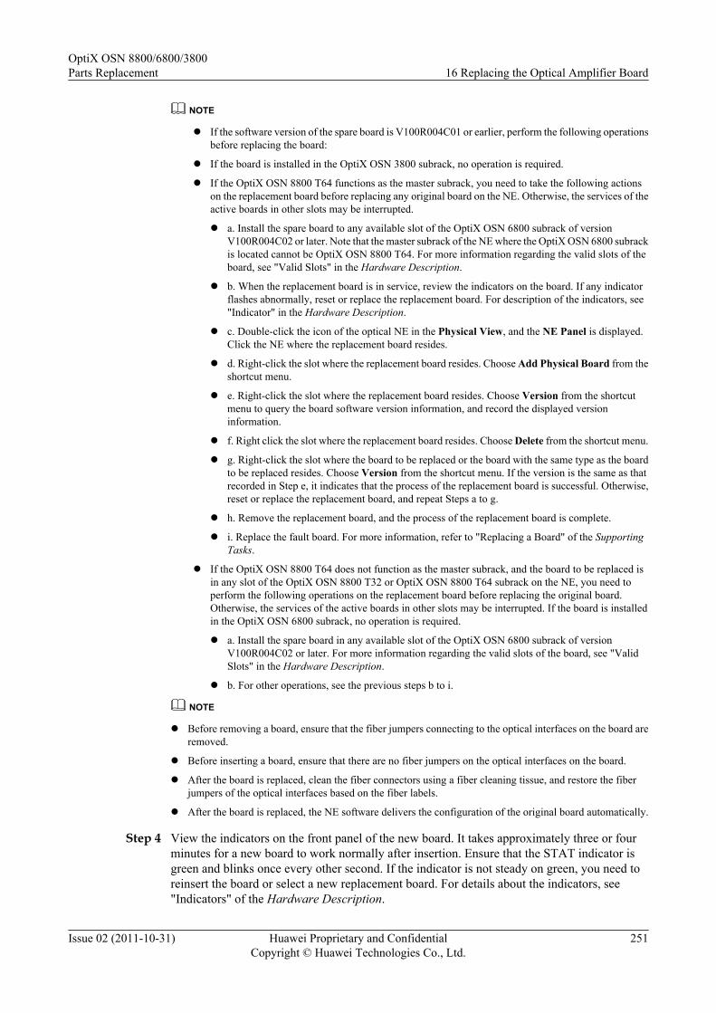
NOTE
l If the software version of the spare board is V100R004C01 or earlier, perform the following operationsbefore replacing the board:
l If the board is installed in the OptiX OSN 3800 subrack, no operation is required.
l If the OptiX OSN 8800 T64 functions as the master subrack, you need to take the following actionson the replacement board before replacing any original board on the NE. Otherwise, the services of theactive boards in other slots may be interrupted.
l a. Install the spare board to any available slot of the OptiX OSN 6800 subrack of versionV100R004C02 or later. Note that the master subrack of the NE where the OptiX OSN 6800 subrackis located cannot be OptiX OSN 8800 T64. For more information regarding the valid slots of theboard, see "Valid Slots" in the Hardware Description.
l b. When the replacement board is in service, review the indicators on the board. If any indicatorflashes abnormally, reset or replace the replacement board. For description of the indicators, see"Indicator" in the Hardware Description.
l c. Double-click the icon of the optical NE in the Physical View, and the NE Panel is displayed.Click the NE where the replacement board resides.
l d. Right-click the slot where the replacement board resides. Choose Add Physical Board from theshortcut menu.
l e. Right-click the slot where the replacement board resides. Choose Version from the shortcutmenu to query the board software version information, and record the displayed versioninformation.
l f. Right click the slot where the replacement board resides. Choose Delete from the shortcut menu.
l g. Right-click the slot where the board to be replaced or the board with the same type as the boardto be replaced resides. Choose Version from the shortcut menu. If the version is the same as thatrecorded in Step e, it indicates that the process of the replacement board is successful. Otherwise,reset or replace the replacement board, and repeat Steps a to g.
l h. Remove the replacement board, and the process of the replacement board is complete.
l i. Replace the fault board. For more information, refer to "Replacing a Board" of the SupportingTasks.
l If the OptiX OSN 8800 T64 does not function as the master subrack, and the board to be replaced isin any slot of the OptiX OSN 8800 T32 or OptiX OSN 8800 T64 subrack on the NE, you need toperform the following operations on the replacement board before replacing the original board.Otherwise, the services of the active boards in other slots may be interrupted. If the board is installedin the OptiX OSN 6800 subrack, no operation is required.
l a. Install the spare board in any available slot of the OptiX OSN 6800 subrack of versionV100R004C02 or later. For more information regarding the valid slots of the board, see "ValidSlots" in the Hardware Description.
l b. For other operations, see the previous steps b to i.
NOTE
l Before removing a board, ensure that the fiber jumpers connecting to the optical interfaces on the board areremoved.
l Before inserting a board, ensure that there are no fiber jumpers on the optical interfaces on the board.
l After the board is replaced, clean the fiber connectors using a fiber cleaning tissue, and restore the fiberjumpers of the optical interfaces based on the fiber labels.
l After the board is replaced, the NE software delivers the configuration of the original board automatically.
Step 4 View the indicators on the front panel of the new board. It takes approximately three or fourminutes for a new board to work normally after insertion. Ensure that the STAT indicator isgreen and blinks once every other second. If the indicator is not steady on green, you need toreinsert the board or select a new replacement board. For details about the indicators, see"Indicators" of the Hardware Description.
OptiX OSN 8800/6800/3800Parts Replacement 16 Replacing the Optical Amplifier Board
Issue 02 (2011-10-31) Huawei Proprietary and ConfidentialCopyright © Huawei Technologies Co., Ltd.
251

Step 5 Query alarms and performances of the local NE and of the opposite NE and confirm that theoriginal alarms or performances are cleared.
----End
OptiX OSN 8800/6800/3800Parts Replacement 16 Replacing the Optical Amplifier Board
Issue 02 (2011-10-31) Huawei Proprietary and ConfidentialCopyright © Huawei Technologies Co., Ltd.
252

17 Replacing the Raman Amplifier Board
This section provides information on how to replace the Raman amplifier board.
Prerequisite
You must be an NMS user with "NE and network operator" authority or higher.
Be aware of the laser security level, possible injury and protective precautions.
Confirm the amount of adopted Raman amplifier board. Be familiar with the fiber connectionbetween the local Raman amplifier board and remote board. Be familiar with the location of theconnector. Take the drawings into the room.
Impact on System
Replacement of boards that process services causes interruption of traditional services.
If ASON services traverse the board to be replaced, optimize the ASON services traversing theboard to other paths (the preset restoration paths of the services are preferred if they do nottraverse the board to be replaced) before board replacement. For optical-layer ASON services,the new paths must be commissioned; otherwise, the services may be interrupted. After boardreplacement, switch the ASON services back to the original paths. If no other paths are availableduring board replacement, the ASON services will be interrupted.
Tools, Equipment, and Materials
ESD bag, U2000
Precautions
WARNINGWhen replacing the Raman amplifier board or before removing or inserting the Raman amplifierboard shut down the pump laser on the CRPC. Otherwise, the laser may bring damage to humanbody.
OptiX OSN 8800/6800/3800Parts Replacement 17 Replacing the Raman Amplifier Board
Issue 02 (2011-10-31) Huawei Proprietary and ConfidentialCopyright © Huawei Technologies Co., Ltd.
253
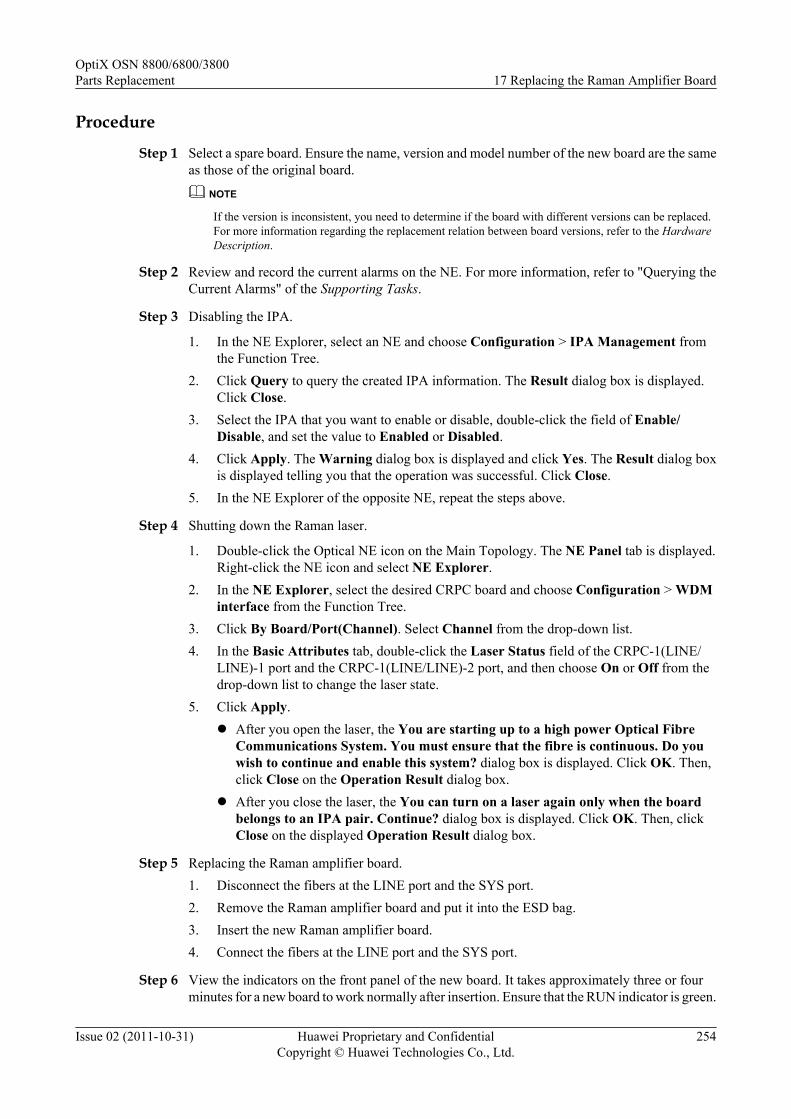
Procedure
Step 1 Select a spare board. Ensure the name, version and model number of the new board are the sameas those of the original board.
NOTE
If the version is inconsistent, you need to determine if the board with different versions can be replaced.For more information regarding the replacement relation between board versions, refer to the HardwareDescription.
Step 2 Review and record the current alarms on the NE. For more information, refer to "Querying theCurrent Alarms" of the Supporting Tasks.
Step 3 Disabling the IPA.
1. In the NE Explorer, select an NE and choose Configuration > IPA Management fromthe Function Tree.
2. Click Query to query the created IPA information. The Result dialog box is displayed.Click Close.
3. Select the IPA that you want to enable or disable, double-click the field of Enable/Disable, and set the value to Enabled or Disabled.
4. Click Apply. The Warning dialog box is displayed and click Yes. The Result dialog boxis displayed telling you that the operation was successful. Click Close.
5. In the NE Explorer of the opposite NE, repeat the steps above.
Step 4 Shutting down the Raman laser.
1. Double-click the Optical NE icon on the Main Topology. The NE Panel tab is displayed.Right-click the NE icon and select NE Explorer.
2. In the NE Explorer, select the desired CRPC board and choose Configuration > WDMinterface from the Function Tree.
3. Click By Board/Port(Channel). Select Channel from the drop-down list.4. In the Basic Attributes tab, double-click the Laser Status field of the CRPC-1(LINE/
LINE)-1 port and the CRPC-1(LINE/LINE)-2 port, and then choose On or Off from thedrop-down list to change the laser state.
5. Click Apply.l After you open the laser, the You are starting up to a high power Optical Fibre
Communications System. You must ensure that the fibre is continuous. Do youwish to continue and enable this system? dialog box is displayed. Click OK. Then,click Close on the Operation Result dialog box.
l After you close the laser, the You can turn on a laser again only when the boardbelongs to an IPA pair. Continue? dialog box is displayed. Click OK. Then, clickClose on the displayed Operation Result dialog box.
Step 5 Replacing the Raman amplifier board.1. Disconnect the fibers at the LINE port and the SYS port.2. Remove the Raman amplifier board and put it into the ESD bag.3. Insert the new Raman amplifier board.4. Connect the fibers at the LINE port and the SYS port.
Step 6 View the indicators on the front panel of the new board. It takes approximately three or fourminutes for a new board to work normally after insertion. Ensure that the RUN indicator is green.
OptiX OSN 8800/6800/3800Parts Replacement 17 Replacing the Raman Amplifier Board
Issue 02 (2011-10-31) Huawei Proprietary and ConfidentialCopyright © Huawei Technologies Co., Ltd.
254

If the indicator is not green, you need to reinsert the board or select a new replacement board.For details about the indicators, see "Indicators" of the Hardware Description.
Step 7 Enable the IPA function, turn on the Raman laser. Check whether the on-off gain of the Ramanamplifier board complies with the specification requirement for the on-off gain of the board. Ifnot, adjust the on-off gain of the board. For the detailed adjusting procedure, see theCommissioning Guide.
NOTE
On-off gain = Optical power on the SYS interface when the laser is enabled - Optical power on the SYSinterface when the Raman laser is disabled
Step 8 Query alarms and performances of the local NE and of the opposite NE and confirm that theoriginal alarms or performances are cleared.
Step 9 Checking and ensuring that the traffic is correct.
NOTE
If there are any other problems, contact Huawei Technical Support.
----End
OptiX OSN 8800/6800/3800Parts Replacement 17 Replacing the Raman Amplifier Board
Issue 02 (2011-10-31) Huawei Proprietary and ConfidentialCopyright © Huawei Technologies Co., Ltd.
255

18 Replacing the Variable OpticalAttenuator Board
This section describes how to replace the variable optical attenuator board.
PrerequisiteYou must be an NMS user with "NE and network operator" authority or higher.
Impact on SystemReplacement of boards that process services causes interruption of traditional services.
If ASON services traverse the board to be replaced, optimize the ASON services traversing theboard to other paths (the preset restoration paths of the services are preferred if they do nottraverse the board to be replaced) before board replacement. For optical-layer ASON services,the new paths must be commissioned; otherwise, the services may be interrupted. After boardreplacement, preset the insertion loss of the new board and re-commission the original paths.Then, switch the ASON services back to the original paths. If no other paths are available duringboard replacement, the ASON services will be interrupted.
During board replacement, the board software takes several minutes to be synchronized. At thispoint, the PROG indicator on the board is blinking green quickly.
Tools, Equipment, and MaterialsESD bag, U2000
Procedure
Step 1 Select a spare board. Ensure the name, version and model number of the new board are the sameas those of the original board.
NOTE
If the version is inconsistent, you need to determine if the board with different versions can be replaced.For more information regarding the replacement relation between board versions, refer to the HardwareDescription.
Step 2 Review and record the current alarms on the NE. For more information, refer to "Querying theCurrent Alarms" of the Supporting Tasks.
OptiX OSN 8800/6800/3800Parts Replacement 18 Replacing the Variable Optical Attenuator Board
Issue 02 (2011-10-31) Huawei Proprietary and ConfidentialCopyright © Huawei Technologies Co., Ltd.
256

Step 3 Inform the onsite maintenance engineer and replace the board. For more information regardinghow to replace a board, refer to "Replacing a Board" of the Supporting Tasks.
NOTE
l If the software version of the spare board is V100R004C01 or earlier, perform the following operationsbefore replacing the board:
l If the board is installed in the OptiX OSN 3800 subrack, no operation is required.
l If the OptiX OSN 8800 T64 functions as the master subrack, you need to take the following actionson the replacement board before replacing any original board on the NE. Otherwise, the services of theactive boards in other slots may be interrupted.
l a. Install the spare board to any available slot of the OptiX OSN 6800 subrack of versionV100R004C02 or later. Note that the master subrack of the NE where the OptiX OSN 6800 subrackis located cannot be OptiX OSN 8800 T64. For more information regarding the valid slots of theboard, see "Valid Slots" in the Hardware Description.
l b. When the replacement board is in service, review the indicators on the board. If any indicatorflashes abnormally, reset or replace the replacement board. For description of the indicators, see"Indicator" in the Hardware Description.
l c. Double-click the icon of the optical NE in the Physical View, and the NE Panel is displayed.Click the NE where the replacement board resides.
l d. Right-click the slot where the replacement board resides. Choose Add Physical Board from theshortcut menu.
l e. Right-click the slot where the replacement board resides. Choose Version from the shortcutmenu to query the board software version information, and record the displayed versioninformation.
l f. Right click the slot where the replacement board resides. Choose Delete from the shortcut menu.
l g. Right-click the slot where the board to be replaced or the board with the same type as the boardto be replaced resides. Choose Version from the shortcut menu. If the version is the same as thatrecorded in Step e, it indicates that the process of the replacement board is successful. Otherwise,reset or replace the replacement board, and repeat Steps a to g.
l h. Remove the replacement board, and the process of the replacement board is complete.
l i. Replace the fault board. For more information, refer to "Replacing a Board" of the SupportingTasks.
l If the OptiX OSN 8800 T64 does not function as the master subrack, and the board to be replaced isin any slot of the OptiX OSN 8800 T32 or OptiX OSN 8800 T64 subrack on the NE, you need toperform the following operations on the replacement board before replacing the original board.Otherwise, the services of the active boards in other slots may be interrupted. If the board is installedin the OptiX OSN 6800 subrack, no operation is required.
l a. Install the spare board in any available slot of the OptiX OSN 6800 subrack of versionV100R004C02 or later. For more information regarding the valid slots of the board, see "ValidSlots" in the Hardware Description.
l b. For other operations, see the previous steps b to i.
NOTE
l Before removing a board, ensure that the fiber jumpers connecting to the optical interfaces on the board areremoved.
l Before inserting a board, ensure that there are no fiber jumpers on the optical interfaces on the board.
l After the board is replaced, clean the fiber connectors using a fiber cleaning tissue, and restore the fiberjumpers of the optical interfaces based on the fiber labels.
l After the board is replaced, the NE software delivers the configuration of the original board automatically.
Step 4 Review the indicators of the new board. It takes ten minutes for a new board to work normallyafter insertion. Ensure that the STAT indicator is steady green. If the indicator gives abnormalindication, you need to reinsert the board, or replace the board again. For more informationregarding indicator definitions, refer to "Indicators" of the Hardware Description.
OptiX OSN 8800/6800/3800Parts Replacement 18 Replacing the Variable Optical Attenuator Board
Issue 02 (2011-10-31) Huawei Proprietary and ConfidentialCopyright © Huawei Technologies Co., Ltd.
257

Step 5 Query alarms and performances of the local NE and of the opposite NE and confirm that theoriginal alarms or performances are cleared.
----End
OptiX OSN 8800/6800/3800Parts Replacement 18 Replacing the Variable Optical Attenuator Board
Issue 02 (2011-10-31) Huawei Proprietary and ConfidentialCopyright © Huawei Technologies Co., Ltd.
258

19 Replacing the Optical SupervisoryChannel Board
This section describes how to replace the optical supervisory channel board.
PrerequisiteYou must be an NMS user with "NE and network operator" authority or higher.
Impact on System
If the OSC board to be replaced is housed on an optical-layer ASON NE, TE links on the FIUboard connected to the OSC board are interrupted or downgraded.
Replacement of boards causes interruption of the optical supervisory channel services.
During board replacement, the board software takes several minutes to be synchronized. At thispoint, the PROG indicator on the board is blinking green quickly.
Tools, Equipment, and Materials
ESD bag, U2000
Procedure
Step 1 Select a spare board. Ensure the name, version and model number of the new board are the sameas those of the original board.
NOTE
If the version is inconsistent, you need to determine if the board with different versions can be replaced.For more information regarding the replacement relation between board versions, refer to the HardwareDescription.
Step 2 Review and record the current alarms on the NE. For more information, refer to "Querying theCurrent Alarms" of the Supporting Tasks.
Step 3 Inform the onsite maintenance engineer and replace the board. For more information regardinghow to replace a board, refer to "Replacing a Board" of the Supporting Tasks.
OptiX OSN 8800/6800/3800Parts Replacement 19 Replacing the Optical Supervisory Channel Board
Issue 02 (2011-10-31) Huawei Proprietary and ConfidentialCopyright © Huawei Technologies Co., Ltd.
259

NOTE
l If the software version of the spare board is V100R004C01 or earlier, perform the following operationsbefore replacing the board:
l If the board is installed in the OptiX OSN 3800 subrack, no operation is required.
l If the OptiX OSN 8800 T64 functions as the master subrack, you need to take the following actionson the replacement board before replacing any original board on the NE. Otherwise, the services of theactive boards in other slots may be interrupted.
l a. Install the spare board to any available slot of the OptiX OSN 6800 subrack of versionV100R004C02 or later. Note that the master subrack of the NE where the OptiX OSN 6800 subrackis located cannot be OptiX OSN 8800 T64. For more information regarding the valid slots of theboard, see "Valid Slots" in the Hardware Description.
l b. When the replacement board is in service, review the indicators on the board. If any indicatorflashes abnormally, reset or replace the replacement board. For description of the indicators, see"Indicator" in the Hardware Description.
l c. Double-click the icon of the optical NE in the Physical View, and the NE Panel is displayed.Click the NE where the replacement board resides.
l d. Right-click the slot where the replacement board resides. Choose Add Physical Board from theshortcut menu.
l e. Right-click the slot where the replacement board resides. Choose Version from the shortcutmenu to query the board software version information, and record the displayed versioninformation.
l f. Right click the slot where the replacement board resides. Choose Delete from the shortcut menu.
l g. Right-click the slot where the board to be replaced or the board with the same type as the boardto be replaced resides. Choose Version from the shortcut menu. If the version is the same as thatrecorded in Step e, it indicates that the process of the replacement board is successful. Otherwise,reset or replace the replacement board, and repeat Steps a to g.
l h. Remove the replacement board, and the process of the replacement board is complete.
l i. Replace the fault board. For more information, refer to "Replacing a Board" of the SupportingTasks.
l If the OptiX OSN 8800 T64 does not function as the master subrack, and the board to be replaced isin any slot of the OptiX OSN 8800 T32 or OptiX OSN 8800 T64 subrack on the NE, you need toperform the following operations on the replacement board before replacing the original board.Otherwise, the services of the active boards in other slots may be interrupted. If the board is installedin the OptiX OSN 6800 subrack, no operation is required.
l a. Install the spare board in any available slot of the OptiX OSN 6800 subrack of versionV100R004C02 or later. For more information regarding the valid slots of the board, see "ValidSlots" in the Hardware Description.
l b. For other operations, see the previous steps b to i.
NOTE
l Before removing a board, ensure that the fiber jumpers connecting to the optical interfaces on the board areremoved.
l Before inserting a board, ensure that there are no fiber jumpers on the optical interfaces on the board.
l After the board is replaced, clean the fiber connectors using a fiber cleaning tissue, and restore the fiberjumpers of the optical interfaces based on the fiber labels.
l After the board is replaced, the NE software delivers the configuration of the original board automatically.
Step 4 Review the indicators of the new board. It takes ten minutes for a new board to work normallyafter insertion. Ensure that the STAT indicator is steady green. If the indicator gives abnormalindication, you need to reinsert the board, or replace the board again. For more informationregarding indicator definitions, refer to "Indicators" of the Hardware Description.
Step 5 Query alarms and performances of the local NE and of the opposite NE and confirm that theoriginal alarms or performances are cleared.
OptiX OSN 8800/6800/3800Parts Replacement 19 Replacing the Optical Supervisory Channel Board
Issue 02 (2011-10-31) Huawei Proprietary and ConfidentialCopyright © Huawei Technologies Co., Ltd.
260

Step 6 If the NE is an ASON NE, for an optical-layer ASON NE, synchronize TE links and verify thatthe status of the TE links and control links corresponding to the board after replacement is correctin the TE link management window.
----End
OptiX OSN 8800/6800/3800Parts Replacement 19 Replacing the Optical Supervisory Channel Board
Issue 02 (2011-10-31) Huawei Proprietary and ConfidentialCopyright © Huawei Technologies Co., Ltd.
261

20 Replacing the Clock Board
This section describes how to replace the clock board.
PrerequisiteYou must be an NMS user with "NE and network operator" authority or higher.
Impact on SystemGenerally, 1+1 protection is configured for STG boards. Replacing an STG board will triggerswitching on the active and standby STG boards and therefore services are not affected.
During board replacement, the board software takes several minutes to be synchronized. At thispoint, the PROG indicator on the board is blinking green quickly.
Tools, Equipment, and MaterialsESD bag, U2000, Screwdriver
Procedure
Step 1 Select a spare board. The name, version, model number, and software version of the new boardmust be the same as those of the original board.
NOTE
If the version is inconsistent, you need to check whether the board with different versions can be replaced.For details about the replacement relationship between board versions, see the Hardware Description.
Step 2 Query and record the current alarms on the NE. For details, see "Querying the Current Alarms"of the Supporting Tasks.
Step 3 For OptiX OSN 8800, perform an active/standby switching on the U2000.
NOTEFor OptiX OSN 8800 T32, assume that the clock board to be replaced is located in slot 42 and it is the maincross-connect board, and that the clock board in slot 44 works normally and the subrack where it is locatedhas no BUS_ERR alarm.
NOTEFor OptiX OSN 8800 T64, assume that the clock board to be replaced is located in slot 75 and it is the maincross-connect board, and that the clock board in slot 86 works normally and the subrack where it is locatedhas no BUS_ERR alarm.
OptiX OSN 8800/6800/3800Parts Replacement 20 Replacing the Clock Board
Issue 02 (2011-10-31) Huawei Proprietary and ConfidentialCopyright © Huawei Technologies Co., Ltd.
262
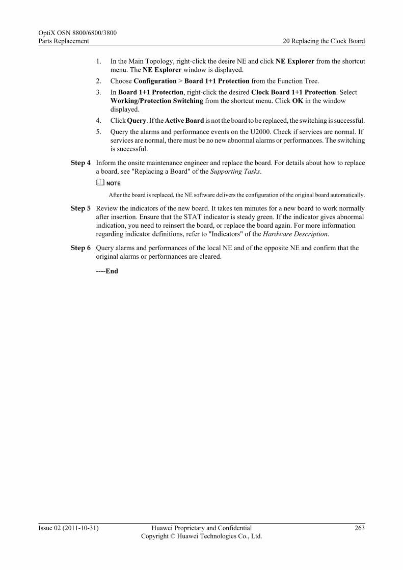
1. In the Main Topology, right-click the desire NE and click NE Explorer from the shortcutmenu. The NE Explorer window is displayed.
2. Choose Configuration > Board 1+1 Protection from the Function Tree.3. In Board 1+1 Protection, right-click the desired Clock Board 1+1 Protection. Select
Working/Protection Switching from the shortcut menu. Click OK in the windowdisplayed.
4. Click Query. If the Active Board is not the board to be replaced, the switching is successful.5. Query the alarms and performance events on the U2000. Check if services are normal. If
services are normal, there must be no new abnormal alarms or performances. The switchingis successful.
Step 4 Inform the onsite maintenance engineer and replace the board. For details about how to replacea board, see "Replacing a Board" of the Supporting Tasks.
NOTE
After the board is replaced, the NE software delivers the configuration of the original board automatically.
Step 5 Review the indicators of the new board. It takes ten minutes for a new board to work normallyafter insertion. Ensure that the STAT indicator is steady green. If the indicator gives abnormalindication, you need to reinsert the board, or replace the board again. For more informationregarding indicator definitions, refer to "Indicators" of the Hardware Description.
Step 6 Query alarms and performances of the local NE and of the opposite NE and confirm that theoriginal alarms or performances are cleared.
----End
OptiX OSN 8800/6800/3800Parts Replacement 20 Replacing the Clock Board
Issue 02 (2011-10-31) Huawei Proprietary and ConfidentialCopyright © Huawei Technologies Co., Ltd.
263

21 Replacing the Optical Protection Board
This section describes how to replace the optical protection board.
PrerequisiteYou must be an NMS user with "NE and network operator" authority or higher.
Impact on SystemReplacement of boards that process services causes service interruption.
During board replacement, the board software takes several minutes to be synchronized. At thispoint, the PROG indicator on the board is blinking green quickly.
Tools, Equipment, and MaterialsESD bag, U2000
Procedure
Step 1 Select a spare board. Ensure the name, version and model number of the new board are the sameas those of the original board.
NOTE
If the version is inconsistent, you need to determine if the board with different versions can be replaced.For more information regarding the replacement relation between board versions, refer to the HardwareDescription.
Step 2 Review and record the current alarms on the NE. For more information, refer to "Querying theCurrent Alarms" of the Supporting Tasks.
Step 3 Inform the onsite maintenance engineer and replace the board. For more information regardinghow to replace a board, refer to "Replacing a Board" of the Supporting Tasks.
OptiX OSN 8800/6800/3800Parts Replacement 21 Replacing the Optical Protection Board
Issue 02 (2011-10-31) Huawei Proprietary and ConfidentialCopyright © Huawei Technologies Co., Ltd.
264
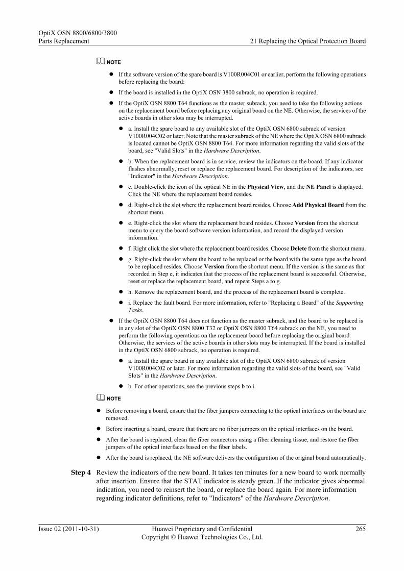
NOTE
l If the software version of the spare board is V100R004C01 or earlier, perform the following operationsbefore replacing the board:
l If the board is installed in the OptiX OSN 3800 subrack, no operation is required.
l If the OptiX OSN 8800 T64 functions as the master subrack, you need to take the following actionson the replacement board before replacing any original board on the NE. Otherwise, the services of theactive boards in other slots may be interrupted.
l a. Install the spare board to any available slot of the OptiX OSN 6800 subrack of versionV100R004C02 or later. Note that the master subrack of the NE where the OptiX OSN 6800 subrackis located cannot be OptiX OSN 8800 T64. For more information regarding the valid slots of theboard, see "Valid Slots" in the Hardware Description.
l b. When the replacement board is in service, review the indicators on the board. If any indicatorflashes abnormally, reset or replace the replacement board. For description of the indicators, see"Indicator" in the Hardware Description.
l c. Double-click the icon of the optical NE in the Physical View, and the NE Panel is displayed.Click the NE where the replacement board resides.
l d. Right-click the slot where the replacement board resides. Choose Add Physical Board from theshortcut menu.
l e. Right-click the slot where the replacement board resides. Choose Version from the shortcutmenu to query the board software version information, and record the displayed versioninformation.
l f. Right click the slot where the replacement board resides. Choose Delete from the shortcut menu.
l g. Right-click the slot where the board to be replaced or the board with the same type as the boardto be replaced resides. Choose Version from the shortcut menu. If the version is the same as thatrecorded in Step e, it indicates that the process of the replacement board is successful. Otherwise,reset or replace the replacement board, and repeat Steps a to g.
l h. Remove the replacement board, and the process of the replacement board is complete.
l i. Replace the fault board. For more information, refer to "Replacing a Board" of the SupportingTasks.
l If the OptiX OSN 8800 T64 does not function as the master subrack, and the board to be replaced isin any slot of the OptiX OSN 8800 T32 or OptiX OSN 8800 T64 subrack on the NE, you need toperform the following operations on the replacement board before replacing the original board.Otherwise, the services of the active boards in other slots may be interrupted. If the board is installedin the OptiX OSN 6800 subrack, no operation is required.
l a. Install the spare board in any available slot of the OptiX OSN 6800 subrack of versionV100R004C02 or later. For more information regarding the valid slots of the board, see "ValidSlots" in the Hardware Description.
l b. For other operations, see the previous steps b to i.
NOTE
l Before removing a board, ensure that the fiber jumpers connecting to the optical interfaces on the board areremoved.
l Before inserting a board, ensure that there are no fiber jumpers on the optical interfaces on the board.
l After the board is replaced, clean the fiber connectors using a fiber cleaning tissue, and restore the fiberjumpers of the optical interfaces based on the fiber labels.
l After the board is replaced, the NE software delivers the configuration of the original board automatically.
Step 4 Review the indicators of the new board. It takes ten minutes for a new board to work normallyafter insertion. Ensure that the STAT indicator is steady green. If the indicator gives abnormalindication, you need to reinsert the board, or replace the board again. For more informationregarding indicator definitions, refer to "Indicators" of the Hardware Description.
OptiX OSN 8800/6800/3800Parts Replacement 21 Replacing the Optical Protection Board
Issue 02 (2011-10-31) Huawei Proprietary and ConfidentialCopyright © Huawei Technologies Co., Ltd.
265
Step 5 Query alarms and performances of the local NE and of the opposite NE and confirm that theoriginal alarms or performances are cleared.
----End
OptiX OSN 8800/6800/3800Parts Replacement 21 Replacing the Optical Protection Board
Issue 02 (2011-10-31) Huawei Proprietary and ConfidentialCopyright © Huawei Technologies Co., Ltd.
266
22 Replacing the Spectrum Analyzer Board
This section describes how to replace the spectrum analyzer board.
PrerequisiteYou must be an NMS user with "NE and network operator" authority or higher.
Impact on SystemDuring board replacement, the board software takes several minutes to be synchronized. At thispoint, the PROG indicator on the board is blinking green quickly.
Tools, Equipment, and MaterialsESD bag, U2000
Procedure
Step 1 Select a spare board. Ensure the name, version and model number of the new board are the sameas those of the original board.
NOTE
If the version is inconsistent, you need to determine if the board with different versions can be replaced.For more information regarding the replacement relation between board versions, refer to the HardwareDescription.
Step 2 Review and record the current alarms on the NE. For more information, refer to "Querying theCurrent Alarms" of the Supporting Tasks.
Step 3 Inform the onsite maintenance engineer and replace the board. For more information regardinghow to replace a board, refer to "Replacing a Board" of the Supporting Tasks.
OptiX OSN 8800/6800/3800Parts Replacement 22 Replacing the Spectrum Analyzer Board
Issue 02 (2011-10-31) Huawei Proprietary and ConfidentialCopyright © Huawei Technologies Co., Ltd.
267

NOTE
l If the software version of the spare board is V100R004C01 or earlier, perform the following operationsbefore replacing the board:
l If the board is installed in the OptiX OSN 3800 subrack, no operation is required.
l If the OptiX OSN 8800 T64 functions as the master subrack, you need to take the following actionson the replacement board before replacing any original board on the NE. Otherwise, the services of theactive boards in other slots may be interrupted.
l a. Install the spare board to any available slot of the OptiX OSN 6800 subrack of versionV100R004C02 or later. Note that the master subrack of the NE where the OptiX OSN 6800 subrackis located cannot be OptiX OSN 8800 T64. For more information regarding the valid slots of theboard, see "Valid Slots" in the Hardware Description.
l b. When the replacement board is in service, review the indicators on the board. If any indicatorflashes abnormally, reset or replace the replacement board. For description of the indicators, see"Indicator" in the Hardware Description.
l c. Double-click the icon of the optical NE in the Physical View, and the NE Panel is displayed.Click the NE where the replacement board resides.
l d. Right-click the slot where the replacement board resides. Choose Add Physical Board from theshortcut menu.
l e. Right-click the slot where the replacement board resides. Choose Version from the shortcutmenu to query the board software version information, and record the displayed versioninformation.
l f. Right click the slot where the replacement board resides. Choose Delete from the shortcut menu.
l g. Right-click the slot where the board to be replaced or the board with the same type as the boardto be replaced resides. Choose Version from the shortcut menu. If the version is the same as thatrecorded in Step e, it indicates that the process of the replacement board is successful. Otherwise,reset or replace the replacement board, and repeat Steps a to g.
l h. Remove the replacement board, and the process of the replacement board is complete.
l i. Replace the fault board. For more information, refer to "Replacing a Board" of the SupportingTasks.
l If the OptiX OSN 8800 T64 does not function as the master subrack, and the board to be replaced isin any slot of the OptiX OSN 8800 T32 or OptiX OSN 8800 T64 subrack on the NE, you need toperform the following operations on the replacement board before replacing the original board.Otherwise, the services of the active boards in other slots may be interrupted. If the board is installedin the OptiX OSN 6800 subrack, no operation is required.
l a. Install the spare board in any available slot of the OptiX OSN 6800 subrack of versionV100R004C02 or later. For more information regarding the valid slots of the board, see "ValidSlots" in the Hardware Description.
l b. For other operations, see the previous steps b to i.
NOTE
l Before removing a board, ensure that the fiber jumpers connecting to the optical interfaces on the board areremoved.
l Before inserting a board, ensure that there are no fiber jumpers on the optical interfaces on the board.
l After the board is replaced, clean the fiber connectors using a fiber cleaning tissue, and restore the fiberjumpers of the optical interfaces based on the fiber labels.
l After the board is replaced, the NE software delivers the configuration of the original board automatically.
Step 4 Review the indicators of the new board. It takes ten minutes for a new board to work normallyafter insertion. Ensure that the STAT indicator is steady green. If the indicator gives abnormalindication, you need to reinsert the board, or replace the board again. For more informationregarding indicator definitions, refer to "Indicators" of the Hardware Description.
OptiX OSN 8800/6800/3800Parts Replacement 22 Replacing the Spectrum Analyzer Board
Issue 02 (2011-10-31) Huawei Proprietary and ConfidentialCopyright © Huawei Technologies Co., Ltd.
268

Step 5 Query alarms and performances of the local NE and of the opposite NE and confirm that theoriginal alarms or performances are cleared.
----End
OptiX OSN 8800/6800/3800Parts Replacement 22 Replacing the Spectrum Analyzer Board
Issue 02 (2011-10-31) Huawei Proprietary and ConfidentialCopyright © Huawei Technologies Co., Ltd.
269

23 Replacing the Optical Power andDispersion Equalizing Board
This section describes how to replace the optical power and dispersion equalizing board.
PrerequisiteYou must be an NMS user with "NE and network operator" authority or higher.
Impact on System
Replacement of boards that process services causes interruption of traditional services.
If ASON services traverse the board to be replaced, optimize the ASON services traversing theboard to other paths (the preset restoration paths of the services are preferred if they do nottraverse the board to be replaced) before board replacement. For optical-layer ASON services,the new paths must be commissioned; otherwise, the services may be interrupted. After boardreplacement, switch the ASON services back to the original paths. If no other paths are availableduring board replacement, the ASON services will be interrupted.
During board replacement, the board software takes several minutes to be synchronized. At thispoint, the PROG indicator on the board is blinking green quickly.
Tools, Equipment, and Materials
ESD bag, U2000
Procedure
Step 1 Select a spare board. Ensure the name, version and model number of the new board are the sameas those of the original board.
NOTE
If the version is inconsistent, you need to determine if the board with different versions can be replaced.For more information regarding the replacement relation between board versions, refer to the HardwareDescription.
Step 2 Review and record the current alarms on the NE. For more information, refer to "Querying theCurrent Alarms" of the Supporting Tasks.
OptiX OSN 8800/6800/3800Parts Replacement
23 Replacing the Optical Power and Dispersion EqualizingBoard
Issue 02 (2011-10-31) Huawei Proprietary and ConfidentialCopyright © Huawei Technologies Co., Ltd.
270

Step 3 Inform the onsite maintenance engineer and replace the board. For more information regardinghow to replace a board, refer to "Replacing a Board" of the Supporting Tasks.
NOTE
l If the software version of the spare board is V100R004C01 or earlier, perform the following operationsbefore replacing the board:
l If the board is installed in the OptiX OSN 3800 subrack, no operation is required.
l If the OptiX OSN 8800 T64 functions as the master subrack, you need to take the following actionson the replacement board before replacing any original board on the NE. Otherwise, the services of theactive boards in other slots may be interrupted.
l a. Install the spare board to any available slot of the OptiX OSN 6800 subrack of versionV100R004C02 or later. Note that the master subrack of the NE where the OptiX OSN 6800 subrackis located cannot be OptiX OSN 8800 T64. For more information regarding the valid slots of theboard, see "Valid Slots" in the Hardware Description.
l b. When the replacement board is in service, review the indicators on the board. If any indicatorflashes abnormally, reset or replace the replacement board. For description of the indicators, see"Indicator" in the Hardware Description.
l c. Double-click the icon of the optical NE in the Physical View, and the NE Panel is displayed.Click the NE where the replacement board resides.
l d. Right-click the slot where the replacement board resides. Choose Add Physical Board from theshortcut menu.
l e. Right-click the slot where the replacement board resides. Choose Version from the shortcutmenu to query the board software version information, and record the displayed versioninformation.
l f. Right click the slot where the replacement board resides. Choose Delete from the shortcut menu.
l g. Right-click the slot where the board to be replaced or the board with the same type as the boardto be replaced resides. Choose Version from the shortcut menu. If the version is the same as thatrecorded in Step e, it indicates that the process of the replacement board is successful. Otherwise,reset or replace the replacement board, and repeat Steps a to g.
l h. Remove the replacement board, and the process of the replacement board is complete.
l i. Replace the fault board. For more information, refer to "Replacing a Board" of the SupportingTasks.
l If the OptiX OSN 8800 T64 does not function as the master subrack, and the board to be replaced isin any slot of the OptiX OSN 8800 T32 or OptiX OSN 8800 T64 subrack on the NE, you need toperform the following operations on the replacement board before replacing the original board.Otherwise, the services of the active boards in other slots may be interrupted. If the board is installedin the OptiX OSN 6800 subrack, no operation is required.
l a. Install the spare board in any available slot of the OptiX OSN 6800 subrack of versionV100R004C02 or later. For more information regarding the valid slots of the board, see "ValidSlots" in the Hardware Description.
l b. For other operations, see the previous steps b to i.
NOTE
l Before removing a board, ensure that the fiber jumpers connecting to the optical interfaces on the board areremoved.
l Before inserting a board, ensure that there are no fiber jumpers on the optical interfaces on the board.
l After the board is replaced, clean the fiber connectors using a fiber cleaning tissue, and restore the fiberjumpers of the optical interfaces based on the fiber labels.
l After the board is replaced, the NE software delivers the configuration of the original board automatically.
Step 4 Query alarms and performances of the local NE and of the opposite NE and confirm that theoriginal alarms or performances are cleared.
----End
OptiX OSN 8800/6800/3800Parts Replacement
23 Replacing the Optical Power and Dispersion EqualizingBoard
Issue 02 (2011-10-31) Huawei Proprietary and ConfidentialCopyright © Huawei Technologies Co., Ltd.
271

24 Replacing the DAS1 Board
This section describes how to replace the DAS1 board.
PrerequisiteYou must be an NMS user with "NE and network operator" authority or higher.
Impact on SystemReplacement of boards that process services causes interruption of traditional services.
If ASON services traverse the board to be replaced, optimize the ASON services traversing theboard to other paths (the preset restoration paths of the services are preferred if they do nottraverse the board to be replaced) before board replacement. For optical-layer ASON services,the new paths must be commissioned; otherwise, the services may be interrupted. After boardreplacement, preset the insertion loss of the new board and re-commission the original paths.Then, switch the ASON services back to the original paths. If no other paths are available duringboard replacement, the ASON services will be interrupted.
If the OSC board to be replaced is housed on an optical-layer ASON NE, TE links on the FIUboard connected to the OSC board are interrupted or downgraded.
Replacement of boards causes interruption of the optical supervisory channel services.
During board replacement, the board software takes several minutes to be synchronized. At thispoint, the PROG indicator on the board is blinking green quickly.
Tools, Equipment, and MaterialsESD bag, U2000
Procedure
Step 1 Select a spare board. Ensure the name, version and model number of the new board are the sameas those of the original board.
NOTE
If the version is inconsistent, you need to determine if the board with different versions can be replaced.For more information regarding the replacement relation between board versions, refer to the HardwareDescription.
OptiX OSN 8800/6800/3800Parts Replacement 24 Replacing the DAS1 Board
Issue 02 (2011-10-31) Huawei Proprietary and ConfidentialCopyright © Huawei Technologies Co., Ltd.
272

Step 2 Review and record the current alarms on the NE. For more information, refer to "Querying theCurrent Alarms" of the Supporting Tasks.
Step 3 Inform the onsite maintenance engineer and replace the board. For more information regardinghow to replace a board, refer to "Replacing a Board" of the Supporting Tasks.
NOTE
l If the software version of the spare board is V100R004C01 or earlier, perform the following operationsbefore replacing the board:
l If the board is installed in the OptiX OSN 3800 subrack, no operation is required.
l If the OptiX OSN 8800 T64 functions as the master subrack, you need to take the following actionson the replacement board before replacing any original board on the NE. Otherwise, the services of theactive boards in other slots may be interrupted.
l a. Install the spare board to any available slot of the OptiX OSN 6800 subrack of versionV100R004C02 or later. Note that the master subrack of the NE where the OptiX OSN 6800 subrackis located cannot be OptiX OSN 8800 T64. For more information regarding the valid slots of theboard, see "Valid Slots" in the Hardware Description.
l b. When the replacement board is in service, review the indicators on the board. If any indicatorflashes abnormally, reset or replace the replacement board. For description of the indicators, see"Indicator" in the Hardware Description.
l c. Double-click the icon of the optical NE in the Physical View, and the NE Panel is displayed.Click the NE where the replacement board resides.
l d. Right-click the slot where the replacement board resides. Choose Add Physical Board from theshortcut menu.
l e. Right-click the slot where the replacement board resides. Choose Version from the shortcutmenu to query the board software version information, and record the displayed versioninformation.
l f. Right click the slot where the replacement board resides. Choose Delete from the shortcut menu.
l g. Right-click the slot where the board to be replaced or the board with the same type as the boardto be replaced resides. Choose Version from the shortcut menu. If the version is the same as thatrecorded in Step e, it indicates that the process of the replacement board is successful. Otherwise,reset or replace the replacement board, and repeat Steps a to g.
l h. Remove the replacement board, and the process of the replacement board is complete.
l i. Replace the fault board. For more information, refer to "Replacing a Board" of the SupportingTasks.
l If the OptiX OSN 8800 T64 does not function as the master subrack, and the board to be replaced isin any slot of the OptiX OSN 8800 T32 or OptiX OSN 8800 T64 subrack on the NE, you need toperform the following operations on the replacement board before replacing the original board.Otherwise, the services of the active boards in other slots may be interrupted. If the board is installedin the OptiX OSN 6800 subrack, no operation is required.
l a. Install the spare board in any available slot of the OptiX OSN 6800 subrack of versionV100R004C02 or later. For more information regarding the valid slots of the board, see "ValidSlots" in the Hardware Description.
l b. For other operations, see the previous steps b to i.
NOTE
l Before removing a board, ensure that the fiber jumpers connecting to the optical interfaces on the board areremoved.
l Before inserting a board, ensure that there are no fiber jumpers on the optical interfaces on the board.
l After the board is replaced, clean the fiber connectors using a fiber cleaning tissue, and restore the fiberjumpers of the optical interfaces based on the fiber labels.
l After the board is replaced, the NE software delivers the configuration of the original board automatically.
Step 4 Review the indicators of the new board. It takes ten minutes for a new board to work normallyafter insertion. Ensure that the STAT indicator is steady green. If the indicator gives abnormal
OptiX OSN 8800/6800/3800Parts Replacement 24 Replacing the DAS1 Board
Issue 02 (2011-10-31) Huawei Proprietary and ConfidentialCopyright © Huawei Technologies Co., Ltd.
273

indication, you need to reinsert the board, or replace the board again. For more informationregarding indicator definitions, refer to "Indicators" of the Hardware Description.
Step 5 Query alarms and performances of the local NE and of the opposite NE and confirm that theoriginal alarms or performances are cleared.
Step 6 Optional: For an optical-layer ASON NE, synchronize TE links and verify that the status of theTE links and control links corresponding to the board after replacement is correct in the TE linkmanagement window.
NOTE
This step only applies to ASON NEs.
----End
OptiX OSN 8800/6800/3800Parts Replacement 24 Replacing the DAS1 Board
Issue 02 (2011-10-31) Huawei Proprietary and ConfidentialCopyright © Huawei Technologies Co., Ltd.
274

25 Replacing the AUX Board
This section describes how to replace the AUX board.
PrerequisiteYou must be an NMS user with "NE and network operator" authority or higher.
Impact on SystemReplacing the AUX board does not affect services.
When 1+1 protection is provided, replacing the AUX board does not interrupt thecommunication between the NE and the U2000.
When 1+1 protection is not provided, replacing the AUX board interrupts the communicationbetween the NE and the U2000, or the communication between the subrack where the AUXboard is located and the U2000.
Tools, Equipment, and MaterialsESD bag, U2000
Background Information (OptiX OSN 8800)There is no jumper inside the TN51AUX board.
Background Information (OptiX OSN 6800)The AUX board can be used to set the subrack ID. The setting is realized by jumpers.
l The TN11AUX01 has three jumpers, Figure 25-1 shows the jumpers. The bits from highto low are 1-3.
l The TN11AUX02 has eight jumpers, the J14, J17, and J18 jumpers are reserved. Figure25-2 shows the jumpers. The bits from high to low are J16, J15, J4, J3, and J2.
Each jumper represents a binary value: 0 or 1. The three jumpers of the TN11AUX01 can beused to realize eight states that represent decimal values 0–7. The default value of the threejumpers is 000. The five jumpers of the TN11AUX02 can be used to realize 32 states thatrepresent decimal values 0–31. The default value of the three jumpers is 00000.
OptiX OSN 8800/6800/3800Parts Replacement 25 Replacing the AUX Board
Issue 02 (2011-10-31) Huawei Proprietary and ConfidentialCopyright © Huawei Technologies Co., Ltd.
275
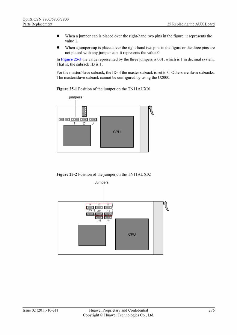
l When a jumper cap is placed over the right-hand two pins in the figure, it represents thevalue 1.
l When a jumper cap is placed over the right-hand two pins in the figure or the three pins arenot placed with any jumper cap, it represents the value 0.
In Figure 25-3 the value represented by the three jumpers is 001, which is 1 in decimal system.That is, the subrack ID is 1.
For the master/slave subrack, the ID of the master subrack is set to 0. Others are slave subracks.The master/slave subrack cannot be configured by using the U2000.
Figure 25-1 Position of the jumper on the TN11AUX01
jumpers
321
CPU
Figure 25-2 Position of the jumper on the TN11AUX02
Jumpers
CPU
J2J3J4
J15J16J17
J14J18
OptiX OSN 8800/6800/3800Parts Replacement 25 Replacing the AUX Board
Issue 02 (2011-10-31) Huawei Proprietary and ConfidentialCopyright © Huawei Technologies Co., Ltd.
276

Figure 25-3 Jumper
1 2 3
jumper cap
representing 0
J4 J3 J2
TN11AUX01
TN11AUX02
jumper cap
representing 0 representing 1
representing 0 representing 0 representing 1
J15
representing 0
J16
representing 0
NOTE
The dashed line between two pins in the figure indicates that a jumper cap may or may not be placed overthe two pins.
Precaution(OptiX OSN 3800)The TN21AUX has threejumpers. Figure 25-4 shows the jumpers.
Figure 25-4 Position of the jumper on the TN21AUX
CPU
Jumper
OptiX OSN 8800/6800/3800Parts Replacement 25 Replacing the AUX Board
Issue 02 (2011-10-31) Huawei Proprietary and ConfidentialCopyright © Huawei Technologies Co., Ltd.
277

Procedure
Step 1 Select a spare board. Ensure the name, version and model number of the new board are the sameas those of the original board.
NOTE
If the version is inconsistent, you need to determine if the board with different versions can be replaced.For more information regarding the replacement relation between board versions, refer to the HardwareDescription.
Step 2 Review and record the current alarms on the NE. For more information, refer to "Querying theCurrent Alarms" of the Supporting Tasks.
Step 3 Inform the on-site maintenance engineer and replace the board. For details about how to replacea board, see "Replacing a Board" of the Supporting Tasks.
NOTE
Before inserting a new AUX board to the original slot, make sure that jumper settings on the new AUX boardare the same as those of the AUX board to be replaced.
NOTE
After the board is replaced, the NE software delivers the configuration of the original board automatically.
Step 4 Review the indicators of the new board. It takes ten minutes for a new board to work normallyafter insertion. Ensure that the STAT indicator is steady green. If the indicator gives abnormalindication, you need to reinsert the board, or replace the board again. For more informationregarding indicator definitions, refer to "Indicators" of the Hardware Description.
Step 5 Query alarms and performances of the local NE and of the opposite NE and confirm that theoriginal alarms or performances are cleared.
----End
OptiX OSN 8800/6800/3800Parts Replacement 25 Replacing the AUX Board
Issue 02 (2011-10-31) Huawei Proprietary and ConfidentialCopyright © Huawei Technologies Co., Ltd.
278

26 Replacing the DCM
This section describes how to replace the DCM.
PrerequisiteNone
Impact on SystemReplacement of DCMs causes interruption of traditional services.
If ASON services traverse the DCM to be replaced, optimize the ASON services traversing theDCM to other paths (the preset restoration paths of the services are preferred if they do nottraverse the DCM to be replaced) before replacement. For optical-layer ASON services, the newpaths must be commissioned; otherwise, the services may be interrupted. After replacement,switch the ASON services back to the original paths. If no other paths are available duringreplacement, the ASON services will be interrupted.
Tools, Equipment, and MaterialsCross screwdriver, screw
Procedure
Step 1 Loosen the screws on the DCM frame for fixing the DCM with the cross screwdriver from below.Remove the DCM from the DCM frame.
NOTE
Each DCM frame can hold up to two DCMs.
Each DCM requires four screws.
Step 2 Put a new DCM on the DCM frame. Tighten the screws to fix the DCM, as shown in Figure26-1.
OptiX OSN 8800/6800/3800Parts Replacement 26 Replacing the DCM
Issue 02 (2011-10-31) Huawei Proprietary and ConfidentialCopyright © Huawei Technologies Co., Ltd.
279

Figure 26-1 Replacing the DCM on the DCM frame
1
23
4
1. DCM 2. DCM frame 3. Mounting ear 4. Screw
----End
OptiX OSN 8800/6800/3800Parts Replacement 26 Replacing the DCM
Issue 02 (2011-10-31) Huawei Proprietary and ConfidentialCopyright © Huawei Technologies Co., Ltd.
280

27 Replacing the Pluggable Optical Module
This section describes how to replace the pluggable optical module (eSFP/XFP).
PrerequisiteYou must be an NMS user with "NE and network operator" authority or higher.
Impact on SystemWhen you replace an eSFP or XFP, query whether the port of the optical module to be replacedis configured with protection. If it is not, replacement of the optical module causes interruptionof traditional services.
If electrical-layer ASON services traverse the port of the optical module to be replaced and theport is not configured with protection, optimize the electrical-layer ASON services traversingthe port to other ports or other boards (the preset restoration paths of the services are preferredif they do not traverse the port of the optical module to be replaced) before module replacement.Then, switch the services back to the original paths after module replacement.
If the port of the optical module to be replaced is configured with protection, module replacementdoes not affect services when the protection switching functions properly.
Tools, Equipment, and MaterialsESD bag, U2000, optical power meter
Precautions
CAUTIONBefore you connect a fiber to a pluggable optical module, test the input optical power of themodule and confirm that the tested input optical power is within the normal range. Otherwise,the input optical power might cross the overload point and the receiver optical module is burntand damaged.The overload optical power point of an APD receiver laser is only -9 dBm, which must be takenwith special caution to prevent the optical module from being burnt or damaged.
OptiX OSN 8800/6800/3800Parts Replacement 27 Replacing the Pluggable Optical Module
Issue 02 (2011-10-31) Huawei Proprietary and ConfidentialCopyright © Huawei Technologies Co., Ltd.
281

Procedure
Step 1 Select a spare pluggable optical module. The part number of the new pluggable optical modulemust be the same as the part number of the original pluggable optical module.
NOTEFor boards supporting TXFP modules, you can use a TXFP module when replacing the XFP module onthese boards. For details on these boards, see Hardware Description.
Step 2 Review and record the current alarms on the NE. For more information, refer to "Querying theCurrent Alarms" of the Supporting Tasks.
Step 3 Query whether the ports of the optical module to be replaced is configured with protection. Fordetails, see 8 Replacing the Optical Transponder Board and 9 Replacing the Tributary andLine Board.l If the port of the optical module to be replaced is not configured with protection, go to Step
4.l If the port of the optical module to be replaced is configured with protection:
– when you replace the optical module of the protection channel, go to Step 4.– when you replace the optical module of the working channel, perform a protection
switching. For details, see 8 Replacing the Optical Transponder Board and 9Replacing the Tributary and Line Board.
Step 4 Remove the fiber on the port of the optical module.
WARNINGCover a fiber with a protection cap immediately after you remove it.
Step 5 Test the input optical power. Prevent the input optical power from crossing the overload point;otherwise, the receiver optical module is burnt and damaged. For the procedure, see the "TestingOptical Power by Using an Optical Power Meter" in Supporting Tasks.
Step 6 Replace the fault optical module. For details, see Figure 27-1.
NOTE
l Before removing an optical module, ensure that the fiber jumpers connecting to the portss of the opticalmodule are removed.
l Before inserting an optical module, ensure that there are no fiber jumpers on the portss of the opticalmodule.
OptiX OSN 8800/6800/3800Parts Replacement 27 Replacing the Pluggable Optical Module
Issue 02 (2011-10-31) Huawei Proprietary and ConfidentialCopyright © Huawei Technologies Co., Ltd.
282
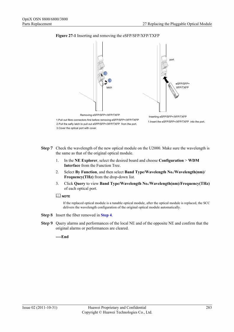
Figure 27-1 Inserting and removing the eSFP/SFP/XFP/TXFP
Inserting eSFP/SFP+/XFP/TXFP
1.Insert the eSFP/SFP+/XFP/TXFP into the port.
Removing eSFP/SFP+/XFP/TXFP
1.Pull out fibre connectors first before removing eSFP/SFP+/XFP/TXFP.2.Pull the safty latch to pull out eSFP/SFP+/XFP/TXFP from the port.
3.Cover the optical port with cover.
1
2
port
eSFP/SFP+XFP/TXFPlatch
Step 7 Check the wavelength of the new optical module on the U2000. Make sure the wavelength isthe same as that of the original optical module.
1. In the NE Explorer, select the desired board and choose Configuration > WDMInterface from the Function Tree.
2. Select By Function, and then select Band Type/Wavelength No./Wavelength(nm)/Frequency(THz) from the drop-down list.
3. Click Query to view Band Type/Wavelength No./Wavelength(nm)/Frequency(THz)of each optical port.
NOTE
If the replaced optical module is a tunable optical module, after the optical module is replaced, the SCCdelivers the wavelength configuration of the original optical module automatically.
Step 8 Insert the fiber removed in Step 4.
Step 9 Query alarms and performances of the local NE and of the opposite NE and confirm that theoriginal alarms or performances are cleared.
----End
OptiX OSN 8800/6800/3800Parts Replacement 27 Replacing the Pluggable Optical Module
Issue 02 (2011-10-31) Huawei Proprietary and ConfidentialCopyright © Huawei Technologies Co., Ltd.
283

28 Replacing the EFI Frame
This section describes how to replace the EFI frame in the OptiX OSN 6800.
Impact on SystemIf the ETH3 interface is in use, the communication between the ETH3 interface and the slavesubrack or the CRPC/ROP board connected to the interface is interrupted during replacementof the EFI frame in the OptiX OSN 6800. If the LAMP1 or LAMP2 interface is in use, thecorresponding alarm indicator on the cabinet does not light up in case of an alarm during thereplacement. If the ALMO or ALMI interface is in use, the alarms generated during thereplacement fail to be output by using the external equipment. The existing services, however,are not affected.
Tools, Equipment and MaterialsESD bag, Philips screwdriver
Procedure
Step 1 Select a new board. The model number of the new board must be the same as that of the originalboard.
Step 2 Review and record the current alarms on the NE. For more information, refer to "Querying theCurrent Alarms" of the Supporting Tasks.
Step 3 Replace the EFI frame on site. For details, see Figure 28-1.
OptiX OSN 8800/6800/3800Parts Replacement 28 Replacing the EFI Frame
Issue 02 (2011-10-31) Huawei Proprietary and ConfidentialCopyright © Huawei Technologies Co., Ltd.
284
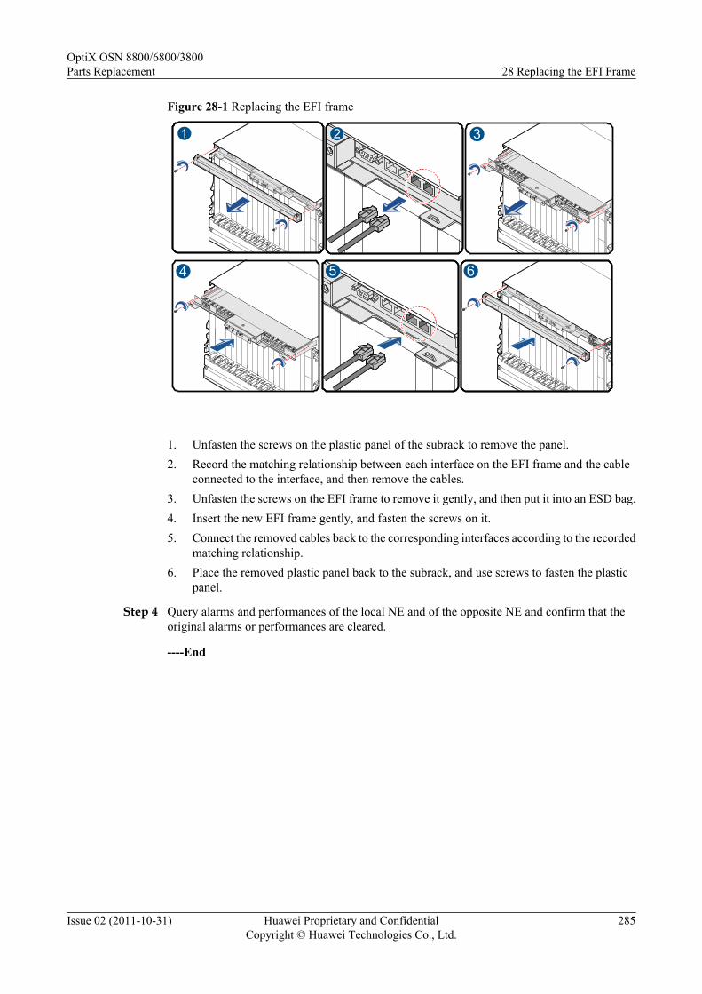
Figure 28-1 Replacing the EFI frame
1. Unfasten the screws on the plastic panel of the subrack to remove the panel.2. Record the matching relationship between each interface on the EFI frame and the cable
connected to the interface, and then remove the cables.3. Unfasten the screws on the EFI frame to remove it gently, and then put it into an ESD bag.4. Insert the new EFI frame gently, and fasten the screws on it.5. Connect the removed cables back to the corresponding interfaces according to the recorded
matching relationship.6. Place the removed plastic panel back to the subrack, and use screws to fasten the plastic
panel.
Step 4 Query alarms and performances of the local NE and of the opposite NE and confirm that theoriginal alarms or performances are cleared.
----End
OptiX OSN 8800/6800/3800Parts Replacement 28 Replacing the EFI Frame
Issue 02 (2011-10-31) Huawei Proprietary and ConfidentialCopyright © Huawei Technologies Co., Ltd.
285

29 Replacing the EFI Board
This section describes how to replace the EFI board in the OptiX OSN 8800.
Prerequisite
You must be an NMS user with "NE and network operator" authority or higher.
Impact on System
Replacement of the EFI interrupts alarm signal input and output, communication amongsubracks, and communication between NE and U2000. In addition, services may be interrupted.
Tools, Equipment, and Materials
ESD bag, U2000
Background Information
Subrack ID can be set by DIP switch on EFI board.
l For OptiX OSN 8800 T64 and OptiX OSN 8800 T32: The TN51EFI2 board is connectedto the master subrack through the ETH1, ETH2, or ETH3 interface. The ID of each subrackis set by using two DIP switches on the TN51EFI1 board.
l For OptiX OSN 8800 T16: The TN16EFI board is connected to the master subrack throughthe ETH1, ETH2, or ETH3 interface. The ID of each subrack is set by using two DIPswitches on the TN16EFI board.
The value that can be set by using each of the two DIP switches on the TN51EFI1/TN16EFIboard is a binary value 0 or 1. ID1-ID4 correspond to bits 1-4 of SW2, and ID5-ID8corresponding to bits 1-4 of SW1. Among these ID values, only ID1-ID5 are valid. ID6 -ID8are reserved. The bits from high to low are ID5-ID1, by which a maximum of 32 states can beset. The value is 00000 by default. "0" indicates the master subrack. The other values indicateslave subracks
Figure 29-1 shows the position of the DIP switches on the TN51EFI1 board, Figure 29-2showsthe position of the DIP switches on the TN16EFI board. The value represented by the ID5-ID1is 00001, which is 1 in decimal system. That is, the subrack ID is 1. When the DIP switch istoggle to ON, the value of the corresponding bit is set to 0.
OptiX OSN 8800/6800/3800Parts Replacement 29 Replacing the EFI Board
Issue 02 (2011-10-31) Huawei Proprietary and ConfidentialCopyright © Huawei Technologies Co., Ltd.
286

NOTEFor details about the principle for configuring the master and slave subracks, see "Master-Slave Subrack" in theProduct Description.
Figure 29-1 Position of the DIP switches on the TN51EFI1 board
ON
SW1
(ID5)ONONON
ON
SW2
ONONON
EFI1
(ID6)(ID7)(ID8)
(ID1)(ID2)(ID3)(ID4)
CPLD
Figure 29-2 Position of the DIP switches on the TN16EFI board
U8SERIAL
NM_ETH2
T1
SW1
SW2
Figure 29-3 The ID of the subrack: 1-15
ONONONON
(ID1)(ID2)(ID3)(ID4)
ONONONON
(ID1)(ID2)(ID3)(ID4)
ONONONON
(ID1)(ID2)(ID3)(ID4)
ONONONON
(ID1)(ID2)(ID3)(ID4)
ONONONON
(ID1)(ID2)(ID3)(ID4)
ONONONON
(ID1)(ID2)(ID3)(ID4)
ONONONON
(ID1)(ID2)(ID3)(ID4)
ONONONON
(ID1)(ID2)(ID3)(ID4)
ONONONON
(ID1)(ID2)(ID3)(ID4)
ONONONON
(ID1)(ID2)(ID3)(ID4)
ONONONON
(ID1)(ID2)(ID3)(ID4)
ONONONON
(ID1)(ID2)(ID3)(ID4)
ONONONON
(ID1)(ID2)(ID3)(ID4)
ONONONON
(ID1)(ID2)(ID3)(ID4)
SW2 Subrack ID SW2 Subrack ID SW2 Subrack ID SW2 Subrack ID SW2 Subrack ID
1 2 3 4 5
6 7 8 9 10
11 12 13 14ONONONON
(ID1)(ID2)(ID3)(ID4)
15
NOTEWhen the ID of the subrack is from 1 to 15, ID5-ID8 of the SW1 must be toggle to ON.
OptiX OSN 8800/6800/3800Parts Replacement 29 Replacing the EFI Board
Issue 02 (2011-10-31) Huawei Proprietary and ConfidentialCopyright © Huawei Technologies Co., Ltd.
287

Figure 29-4 The ID of the subrack: 16-31
SW1 SW2 Subrack ID
16
SW2 Subrack ID
17
SW1 SW2 Subrack ID
18
SW1
19 20 21
22 23 24
25 26 27
ONONONON
(ID1)(ID2)(ID3)(ID4)
ONONONON
(ID5)(ID6)(ID7)(ID8)
ONONONON
(ID1)(ID2)(ID3)(ID4)
ONONONON
(ID5)(ID6)(ID7)(ID8)
ONONONON
(ID1)(ID2)(ID3)(ID4)
ONONONON
(ID5)(ID6)(ID7)(ID8)
ONONONON
(ID1)(ID2)(ID3)(ID4)
ONONONON
(ID5)(ID6)(ID7)(ID8)
ONONONON
(ID5)(ID6)(ID7)(ID8)
ONONONON
(ID1)(ID2)(ID3)(ID4)
ONONONON
(ID1)(ID2)(ID3)(ID4)
ONONONON
(ID5)(ID6)(ID7)(ID8)
ONONONON
(ID5)(ID6)(ID7)(ID8)
ONONONON
(ID1)(ID2)(ID3)(ID4)
ONONONON
(ID1)(ID2)(ID3)(ID4)
ONONONON
(ID5)(ID6)(ID7)(ID8)
ONONONON
(ID5)(ID6)(ID7)(ID8)
ONONONON
(ID1)(ID2)(ID3)(ID4)
ONONONON
(ID1)(ID2)(ID3)(ID4)
ONONONON
(ID5)(ID6)(ID7)(ID8)
ONONONON
(ID5)(ID6)(ID7)(ID8)
ONONONON
(ID1)(ID2)(ID3)(ID4)
ONONONON
(ID1)(ID2)(ID3)(ID4)
ONONONON
(ID5)(ID6)(ID7)(ID8)
28 29 30ONONONON
(ID1)(ID2)(ID3)(ID4)
ONONONON
(ID5)(ID6)(ID7)(ID8)
ONONONON
(ID5)(ID6)(ID7)(ID8)
ONONONON
(ID1)(ID2)(ID3)(ID4)
ONONONON
(ID1)(ID2)(ID3)(ID4)
ONONONON
(ID5)(ID6)(ID7)(ID8)
31ONONONON
(ID1)(ID2)(ID3)(ID4)
ONONONON
(ID5)(ID6)(ID7)(ID8)
Procedure
Step 1 Select a spare board. Ensure the name, version and model number of the new board are the sameas those of the original board.
NOTE
If the version is inconsistent, you need to determine if the board with different versions can be replaced.For more information regarding the replacement relation between board versions, refer to the HardwareDescription.
Step 2 Review and record the current alarms on the NE. For more information, refer to "Querying theCurrent Alarms" of the Supporting Tasks.
Step 3 Follow the steps below to replace the EFI on site.
NOTE
Before inserting a new EFI board to the original slot, ensure that DIP switch on the new EFI board is the sameas that of the EFI board to be replaced.
1. Record the mapping relationships of the board interfaces and the cables and wires.
2. Remove the cables and wires on the connectors.
3. TN51EFI board: Loosen the screw at the top right corner of the board. TN16EFI board:Loosen two screws at the top corner of the board.
4. Gently pull out the board and put it into the ESD bag.
5. Insert the new board gently.
6. View the subrack ID displayed in the LCD screen on the front panel of the board to ensurethat the subrack ID is correct. For OptiX OSN 8800 T64 and OptiX OSN 8800 T32, thesubrack ID is displayed on the SCC board; For OptiX OSN 8800 T16, the subrack ID isdisplayed on the AUX board.
OptiX OSN 8800/6800/3800Parts Replacement 29 Replacing the EFI Board
Issue 02 (2011-10-31) Huawei Proprietary and ConfidentialCopyright © Huawei Technologies Co., Ltd.
288

7. TN51EFI board: Tighten the captive screw at the top right corner of the board. TN16EFIboard: Tighten two captive screws at the top corner of the board.
8. Connect the cables and wires on the connectors as recorded.
Step 4 Verify that there are no faults on the board. Query the U2000 for alarms on the NE and ensurethat the alarm detected in Step 2 is cleared.
----End
OptiX OSN 8800/6800/3800Parts Replacement 29 Replacing the EFI Board
Issue 02 (2011-10-31) Huawei Proprietary and ConfidentialCopyright © Huawei Technologies Co., Ltd.
289
30 Replacing the PIU Board
This section describes how to replace the PIU board.
Prerequisite
You must be an NMS user with "NE and network operator" authority or higher.
Impact on System
When 1+1 backup is provided, replacing the standby PIU brings no impact on services.
Tools, Equipment, and Materials
ESD bag, U2000, Cross screwdriver
Procedure (OptiX OSN 6800/3800)
Step 1 Select a spare board. Ensure the name, version and model number of the new board are the sameas those of the original board.
NOTE
If the version is inconsistent, you need to determine if the board with different versions can be replaced.For more information regarding the replacement relation between board versions, refer to the HardwareDescription.
Step 2 Review and record the current alarms on the NE. For more information, refer to "Querying theCurrent Alarms" of the Supporting Tasks.
Step 3 Switch off the corresponding power output switch on the DC power distribution unit on the topof the cabinet.
CAUTIONl For OptiX OSN 6800, there are 6 power output switches on each of the right and left sides
of the DC power distribution unit. Do shut down the corresponding switch.
OptiX OSN 8800/6800/3800Parts Replacement 30 Replacing the PIU Board
Issue 02 (2011-10-31) Huawei Proprietary and ConfidentialCopyright © Huawei Technologies Co., Ltd.
290

Figure 30-1 Mapping relationship table of the PIU boards and power supply switches in theOptiX OSN 6800
21 3 4 5 621 3 4 5 6
SW5 (A)
SW5 (B)
SW4(A)
SW4 (B)
SW3(A)
SW3 (B)
SW2(A)
SW2 (B)
Step 4 Remove the power plug on the PIU board to be replaced.
Step 5 Inform the onsite maintenance engineer and replace the board. For details about how to replacea board, see "Replacing a Board" of the Supporting Tasks
Step 6 After the replacement, put the power plug back to the new PIU board. Switch on thecorresponding power switch on the DC power distribution unit.
Step 7 Query alarms and performances of the local NE and of the opposite NE and confirm that theoriginal alarms or performances are cleared.
----End
Procedure (OptiX OSN 8800)
Step 1 Select a spare board. Ensure the name, version and model number of the new board are the sameas those of the original board.
OptiX OSN 8800/6800/3800Parts Replacement 30 Replacing the PIU Board
Issue 02 (2011-10-31) Huawei Proprietary and ConfidentialCopyright © Huawei Technologies Co., Ltd.
291

NOTE
If the version is inconsistent, you need to determine if the board with different versions can be replaced.For more information regarding the replacement relation between board versions, refer to the HardwareDescription.
Step 2 Review and record the current alarms on the NE. For more information, refer to "Querying theCurrent Alarms" of the Supporting Tasks.
Step 3 Switch off the corresponding power output switch on the DC power distribution unit on the topof the cabinet.
CAUTIONl For OptiX OSN 8800, there are 4 power output switches on each of the right and left sides
of the DC power distribution unit. Do shut down the corresponding switch.
Figure 30-2 Mapping relationship table of the PIU boards and power supply switches in theOptiX OSN 8800
Subrack A
Subrack B
SW1(A)SW2(A)
SW2(B)SW1(B)
SW3(A)SW4(A)
SW4(B)SW3(B)
8800 I
8800 I
8800 T32
8800 T32
OptiX OSN 8800/6800/3800Parts Replacement 30 Replacing the PIU Board
Issue 02 (2011-10-31) Huawei Proprietary and ConfidentialCopyright © Huawei Technologies Co., Ltd.
292

Subrack A
Subrack B
8800 T64
8800 T32
SW1(A)SW2(A) SW1(B)
SW2(B)
SW3(B)SW4(B)
SW4(A)SW3(A)
OptiX OSN 8800/6800/3800Parts Replacement 30 Replacing the PIU Board
Issue 02 (2011-10-31) Huawei Proprietary and ConfidentialCopyright © Huawei Technologies Co., Ltd.
293

8800 T16
8800 T16
8800 T16
8800 T16
SW4(A)
SW3(A)
SW2(A)
SW1(A) SW1(B)
SW2(B)
SW3(B)
SW4(B)
Step 4 Remove the plastic cover on the power input terminal block on the PIU board by using the crossscrewdrivers.
Step 5 Unfasten the nuts on the power input terminals by using the cross screwdrivers and remove thepower cables.
Step 6 Follow the steps below to replace the PIU:
OptiX OSN 8800/6800/3800Parts Replacement 30 Replacing the PIU Board
Issue 02 (2011-10-31) Huawei Proprietary and ConfidentialCopyright © Huawei Technologies Co., Ltd.
294

1. Loosen the screw at the top right corner of the unit.2. Remove the unit gently, and put it into the ESD bag.3. Insert the new PIU gently.4. Tighten the screw at the top right corner of the unit.
Step 7 After the replacement, put the power cables back to the new PIU board. Switch on thecorresponding power switch on the DC power distribution unit.
Step 8 Query alarms and performances of the local NE and of the opposite NE and confirm that theoriginal alarms or performances are cleared.
----End
OptiX OSN 8800/6800/3800Parts Replacement 30 Replacing the PIU Board
Issue 02 (2011-10-31) Huawei Proprietary and ConfidentialCopyright © Huawei Technologies Co., Ltd.
295
31 Replacing the Power Switch on the DCPower Distribution Box
This section describes how to replace a faulty power switch on the DC power distribution box.
PrerequisiteNone
Impact on SystemNone
Tools, Equipment and MaterialsCross screwdriver, screw
Background Informationl OptiX OSN 8800 uses the standard -48V/-60V DC power supply. The -48V/-60 DC power
supply is distributed to the working subracks through the power box shown in Figure31-1 and Figure 31-2 .
l OptiX OSN 6800 uses the standard -48V/-60V DC power supply. The -48V/-60 DC powersupply is distributed to the working subracks through the power box shown in Figure31-3.
OptiX OSN 8800/6800/3800Parts Replacement
31 Replacing the Power Switch on the DC Power DistributionBox
Issue 02 (2011-10-31) Huawei Proprietary and ConfidentialCopyright © Huawei Technologies Co., Ltd.
296
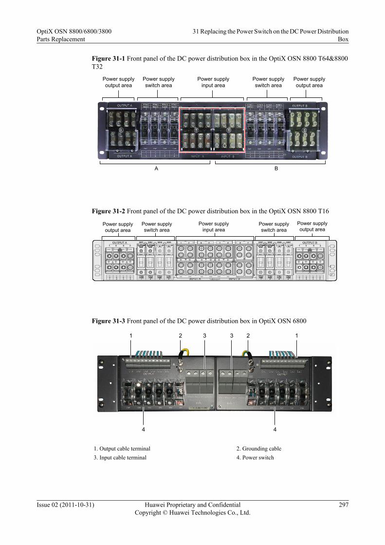
Figure 31-1 Front panel of the DC power distribution box in the OptiX OSN 8800 T64&8800T32
Power supply output area
Power supply output area
Power supply switch area
Power supply switch area
Power supply input area
A B
Figure 31-2 Front panel of the DC power distribution box in the OptiX OSN 8800 T16
1+-
2+-
3+-
4+-
1+-
2+-
3+-
4+-
Power supply output area
Power supply switch area
Power supply input area
Power supply switch area
Power supply output area
Figure 31-3 Front panel of the DC power distribution box in OptiX OSN 6800
1 2 3 3 2 1
4 4
1. Output cable terminal 2. Grounding cable3. Input cable terminal 4. Power switch
OptiX OSN 8800/6800/3800Parts Replacement
31 Replacing the Power Switch on the DC Power DistributionBox
Issue 02 (2011-10-31) Huawei Proprietary and ConfidentialCopyright © Huawei Technologies Co., Ltd.
297

Procedure
Step 1 Set the faulty switch on the DC power distribution box to the OFF position. The powerdistribution box can be seen in Figure 31-1. There are 4 power switches in each side.
Step 2 Loosen the captive screw on the front panel of the faulty power switch with the cross screwdriveras shown in Figure 31-4. Remove the faulty power switch from the DC power distribution box.
Figure 31-4 Loosen the captive screw
Step 3 Loosen the two screws between the faulty power switch and the plastic protective shell toseparate the power switch from the protective shell. See Figure 31-5.
Figure 31-5 Loosen the two screws between the faulty power switch and the plastic protectiveshell
OptiX OSN 8800/6800/3800Parts Replacement
31 Replacing the Power Switch on the DC Power DistributionBox
Issue 02 (2011-10-31) Huawei Proprietary and ConfidentialCopyright © Huawei Technologies Co., Ltd.
298

Step 4 Get a new power switch, and ensure the state is OFF.
Step 5 Install the new power switch and the plastic protective shell.
Step 6 Insert the new power switch into the DC power distribution box. Tighten the captive screw onthe front panel of the new power switch with the cross screwdriver.
Step 7 Set the new power switch to the state of ON. Check RUN indicator of the PIU board whichconnects to the power distribution box through the new power switch.l If the RUN indicator is on, it indicates the new power distribution unit works normally.l If the RUN indicator is off, check if the connection of the input power cables is correct:
– if the connection is wrong, reconnect the cables.– if the connection is correct, replace the power switch again.
----End
OptiX OSN 8800/6800/3800Parts Replacement
31 Replacing the Power Switch on the DC Power DistributionBox
Issue 02 (2011-10-31) Huawei Proprietary and ConfidentialCopyright © Huawei Technologies Co., Ltd.
299

32 Replacing the Fan Tray Assembly
This section describes how to replace the fan tray assembly.
PrerequisiteYou must be an NMS user with "NE and network operator" authority or higher.
Impact on SystemThe equipment can work normally for three minutes when no fans are provided. When there isa fault in the fan tray assembly, replace it immediately to avoid any damage to the equipmentdue to power heat dissipation.
Replacing the fan tray assembly does not interrupt the service.
Tools, Equipment, and MaterialsESD bag, U2000
Procedure
Step 1 Select a spare board. Ensure the name, version and model number of the new board are the sameas those of the original board.
NOTE
If the version is inconsistent, you need to determine if the board with different versions can be replaced.For more information regarding the replacement relation between board versions, refer to the HardwareDescription.
Step 2 Review and record the current alarms on the NE. For more information, refer to "Querying theCurrent Alarms" of the Supporting Tasks.
Step 3 Follow the steps below to replace the fan try assembly on site.1. Remove the faulty fan tray assembly.2. Insert a spare fan tray assembly immediately.3. put the fan tray assembly replaced into an ESD bag.
NOTEWhen the subrack is powered on for the first time, the fans rotate at a low or medium speed for the first20 minutes. After the 20 minutes, the fans rotate at the specified speed.
OptiX OSN 8800/6800/3800Parts Replacement 32 Replacing the Fan Tray Assembly
Issue 02 (2011-10-31) Huawei Proprietary and ConfidentialCopyright © Huawei Technologies Co., Ltd.
300

Step 4 Query alarms and performances of the local NE and of the opposite NE and confirm that theoriginal alarms or performances are cleared.
----End
OptiX OSN 8800/6800/3800Parts Replacement 32 Replacing the Fan Tray Assembly
Issue 02 (2011-10-31) Huawei Proprietary and ConfidentialCopyright © Huawei Technologies Co., Ltd.
301

33 Replacing the Air Filter
Replace the air filter periodically to ensure efficient heat dissipation from the equipment.
PrerequisiteNone
Impact on SystemNone
Tools, Equipment, and MaterialsNone
Precaution
CAUTIONWhen drawing out the air filter during its replacement, do not draw out the fans.Draw out the air filter gently to prevent dust disturbance.
NOTE
It is recommended to replace the air filter every six months.
Procedure (OptiX OSN 8800/6800)
Step 1 Hold the grooves on the two sides of the air filter panel with two fingers and draw out the airfilter. Figure 33-1 and Figure 33-2 shows the position of the air filter.
OptiX OSN 8800/6800/3800Parts Replacement 33 Replacing the Air Filter
Issue 02 (2011-10-31) Huawei Proprietary and ConfidentialCopyright © Huawei Technologies Co., Ltd.
302
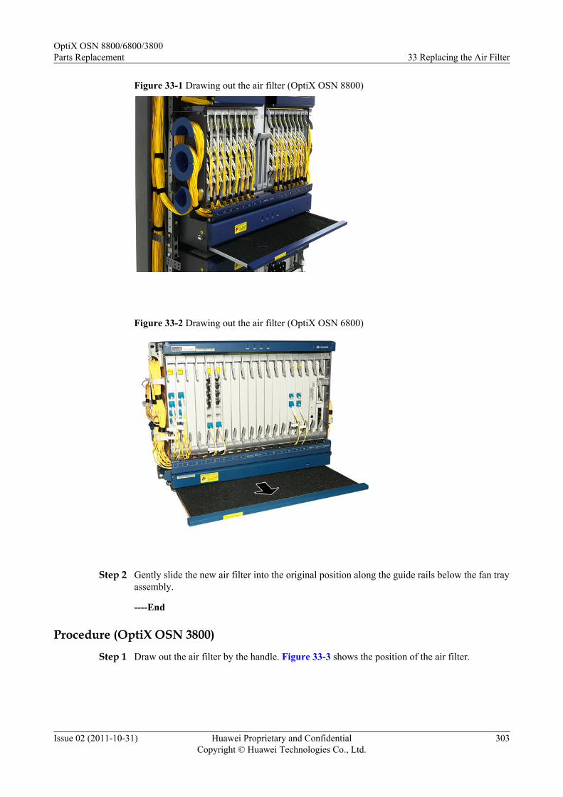
Figure 33-1 Drawing out the air filter (OptiX OSN 8800)
Figure 33-2 Drawing out the air filter (OptiX OSN 6800)
Step 2 Gently slide the new air filter into the original position along the guide rails below the fan trayassembly.
----End
Procedure (OptiX OSN 3800)
Step 1 Draw out the air filter by the handle. Figure 33-3 shows the position of the air filter.
OptiX OSN 8800/6800/3800Parts Replacement 33 Replacing the Air Filter
Issue 02 (2011-10-31) Huawei Proprietary and ConfidentialCopyright © Huawei Technologies Co., Ltd.
303

Figure 33-3 Drawing out the air filter(OptiX OSN 3800)
Air filterFan
Step 2 Gently slide the new air filter into the original position along the guide rails on the left part ofthe fan tray assembly.
----End
OptiX OSN 8800/6800/3800Parts Replacement 33 Replacing the Air Filter
Issue 02 (2011-10-31) Huawei Proprietary and ConfidentialCopyright © Huawei Technologies Co., Ltd.
304
34 Replacing SDI Components
This section describes how to replace a component (such as fan module, power supply module,and control board) on the digital video O/E conversion chassis and how to replace the SDI-specific SFP module on the TOM board.
Prerequisite
None
Impact on Systeml Replacing a fan module has no impact on the existing services.
NOTE
A fan module must be replaced in time after it is damaged. This prevents the SDI from being damageddue to excessively high working temperature.
l Replacing a power supply module has no impact on the existing services if there are activeand standby power supply modules. Otherwise, the digital video O/E conversion chassis ispowered off during the replacement and thus the existing services are interrupted.
l Replacing a control board has no impact on the existing services if there are active andstandby control boards.
NOTE
The preceding components in the digital video O/E conversion chassis are hot-swappable.
l Replacing an SFP module interrupts the existing services.
NOTE
This SFP module is dedicated for the SDI.
Tools, Equipment and Materials
ESD bag, flathead screwdriver
Background Information
The SDI consists of an O/E conversion chassis and the SFP module on the TOM board. The SFPmodule on the TOM board is specific for connecting to the SDI.
OptiX OSN 8800/6800/3800Parts Replacement 34 Replacing SDI Components
Issue 02 (2011-10-31) Huawei Proprietary and ConfidentialCopyright © Huawei Technologies Co., Ltd.
305

ProcedureReplace a fan module, power supply module, or control board according to the following steps.For the steps of replacing an SFP module, see 27 Replacing the Pluggable Optical Module.
Step 1 Select a spare board. The name and model number of the new board must be the same as thoseof the original board.
Step 2 Use a flathead screwdriver to unfasten the fastening screws on the front panel of the module tobe replaced. Then, remove the module from the SDI O/E conversion chassis and put it into anESD bag.
2
1 Power Supply Module
Control Card
Fan Module
Step 3 Insert a new module into the slot that houses the original module.
Step 4 After the new module is positioned properly in the slot, use the flathead screwdriver to tightenthe fastening screws on the front panel.
----End
OptiX OSN 8800/6800/3800Parts Replacement 34 Replacing SDI Components
Issue 02 (2011-10-31) Huawei Proprietary and ConfidentialCopyright © Huawei Technologies Co., Ltd.
306