parts manual 509b & 511b backhoe - talet attachments · parts manual 509b & 511b backhoe...
TRANSCRIPT
12561 2-12-15-2
800-456-7100 I www.paladinattachments.com 503 Gay Street, Delhi, IA 52223, United States of America Copyright ©
PARTS MANUAL
509B & 511B BACKHOE
SERIAL NUMBER: ___________________ Manual Number: PM853 Part Number: 75753 MODEL NUMBER: ___________________ Rev. 2


Limited WarrantyExcept for the Excluded Products as described below, all new products are warranted to be free from defects in material and/or workmanship during the Warranty Period, in accordance with and subject to the terms and conditions of this Limited Warranty.
1. Excluded Products. The following products are excluded from this Limited Warranty:
(a) Any cable, part that engages with the ground (i.e. sprockets), digging chain, bearing, teeth, tamping and/or demolition head, blade cutting edge, pilot bit, auger teeth and broom brush that either constitutes or is part of a product.
(b) Any product, merchandise or component that, in the opinion of Paladin Light Construction1, has been (i) misused; (ii) modified in any unauthorized manner; (iii) altered; (iv) damaged; (v) involved in an accident; or (vi) repaired using parts not obtained through Paladin Light Construction.
2. Warranty Period. The Limited Warranty is provided only to those defects that occur during the Warranty Period, which is the period that begins on the first to occur of: (i) the date of initial purchase by an end-user, (ii) the date the product is first leased or rented, or (iii) the date that is six (6) months after the date of shipment by Paladin Light Construction as evidenced by the invoiced shipment date (the “Commencement Date”) and ends on the date that is twenty-four (24) months after the Commencement Date.
3. Terms and Conditions of Limited Warranty. The following terms and conditions apply to the Limited Warranty hereby provided:
(a) Option to Repair or Replace. Paladin Light Construction shall have the option to repair or replace the product.
(b) Timely Repair and Notice. In order to obtain the Limited Warranty, (i) the product must be repaired within thirty (30) days from the date of failure, and (ii) a claim under the warranty must be submitted to Paladin Light Construction in writing within thirty (30) days from the date of repair.
(c) Return of Defective Part or Product. If requested by Paladin Light Construction, the alleged defective part or product shall be shipped to Paladin Light Construction at its manufacturing facility or other location specified by Paladin Light Construction, with freight PRE-PAID by the claimant, to allow Paladin Light Construction to inspect the part or product.
Claims that fail to comply with any of the above terms and conditions shall be denied.
LIMITATIONS AND EXCLUSIONS.
THIS LIMITED WARRANTY IS IN LIEU OF ALL OTHER WARRANTIES, EXPRESS OR IMPLIED, INCLUDING WITHOUT LIMITATION THE WARRANTIES OF MERCHANTABILITY, FITNESS FOR A PARTICULAR PURPOSE AND ANY WARRANTY BASED ON A COURSE OF DEALING OR USAGE OF TRADE.
IN NO EVENT SHALL PALADIN LIGHT CONSTRUCTION BE LIABLE FOR CONSEQUENTIAL OR SPECIAL DAMAGES.
IN NO EVENT SHALL PALADIN LIGHT CONSTRUCTION BE LIABLE FOR ANY LOSS OR CLAIM IN AN AMOUNT IN EXCESS OF THE PURCHASE PRICE, OR, AT THE OPTION OF PALADIN LIGHT CONSTRUCTION, THE REPAIR OR REPLACEMENT, OF THE PARTICULAR PRODUCT ON WHICH ANY CLAIM OF LOSS OR DAMAGE IS BASED. THIS LIMITATION OF LIABILITY APPLIES IRRESPECTIVE OF WHETHER THE CLAIM IS BASED ON BREACH OF CONTRACT, BREACH OF WARRANTY, NEGLIGENCE OR OTHER CAUSE AND WHETHER THE ALLEGED DEFECT IS DISCOVERABLE OR LATENT.
1Attachment Technologies Inc., a subsidiary of Paladin Brands Holding, Inc. (PBHI) is referred to herein as Paladin Light Construction.
February 10, 201075753 1

THIS PAGEIS INTENTIONALLY
BLANK
2 75753

TABLE OF CONTENTSSERVICE PARTS
12563 1-30-14-2
MAINFRAME ASSEMBLY #116121 Mainframe .............................................................................................................................................. 4-5 Swing Post ............................................................................................................................................. 6-7 Swing Cylinder ....................................................................................................................................... 8-9 Stabilizers .......................................................................................................................................... 10-11 Hose Bundle Clamps ......................................................................................................................... 12-13
509B BOOM & DIPPER ASSEMBLY #117946 ............................................................................... 14-17511B BOOM & DIPPER ASSEMBLY #118176 ............................................................................... 18-21
CONSOLE ASSEMBLY #104161 ........................................................................................................ 22-23
VALVE ASSEMBLY #2261 ................................................................................................................... 24-25 Valve #103546 and Service Parts ..................................................................................................... 26-29
CYLINDERS SWING CYLINDER #81827 .............................................................................................................. 30-31 STABILIZER CYLINDER #86605 ...................................................................................................... 32-33 509 BOOM CYLINDER #86231 ........................................................................................................ 34-35 511 BOOM CYLINDER #82625 ......................................................................................................... 36-37 509 DIPPER CYLINDER #86236 ...................................................................................................... 38-39 511 DIPPER CYLINDER #87029 ...................................................................................................... 40-41 BUCKET CYLINDER #117548 .......................................................................................................... 42-43
HOSE SETS MAINFRAME HOSE SET #103646 ................................................................................................... 44-45 509 BOOM & DIPPER HOSE SET #85448 ....................................................................................... 46-47 511 BOOM & DIPPER HOSE SET #86982 ....................................................................................... 48-49
STABILIZER PAD OPTIONS FLAT STABILIZER PAD ASSEMBLY #81861 .................................................................................... 50-51 GROUSER STABILIZER PAD ASSEMBLY #81860 .......................................................................... 50-51 RUBBER STABILIZER PAD ASSEMBLY #81862 ............................................................................. 50-51 FLIP-OVER STABILIZER PAD ASSEMBLY #83058 ......................................................................... 52-53
OPTIONAL STABILIZER CYLINDER COVER #86706 ................................................................ 54-55
SEVERE DUTY BUCKETS ................................................................................................................... 56-57
509B FIRST LINE REPAIR KIT #86320............................................................................................ 58-59511B FIRST LINE REPAIR KIT #87500 ............................................................................................ 60-61
DECALS ...................................................................................................................................................... 62-65
75753 3

MAINFRAME ASSEMBLY
12564 11-19-13
ASSEMBLY #116121MAINFRAME
1213
1114
15
15
16
17
17
18
19
9
7
10
6
4
32
111
1
21
22
23
24
25
26
34
2728
29
30
3132
33
23
4
5
6
7
8
20
4 75753

12565 11-19-13
ITEM REQ’D PART NO. DESCRIPTION
1 2 1043 .38" UNC X 1.00" Hex Capscrew 2 2 1514 .38" Flat Washer 3 2 81807 Spacer Tube 4 2 81592 Pin 2 6616 Grease Zerk 5 1 83977 Thrust Washer 1.38" X .125" 6 2 1929 Snap Ring 7 2 6615 Bearing 8 1 86195 Mainframe (Includes (4) 83815 Bushings - Installed with Locktite Grade 680) 9 1 82090 Swing Lock Pin 10 As Req'd 83975 Thrust Washer 1.38" X .031" As Req'd 83976 Thrust Washer 1.38" X .093" As Req'd 83977 Thrust Washer 1.38" X .125" 11 3 1503 .38" Lock Washer 12 2 6186 Hose Clamp 13 2 6799 Spacer Tube 14 2 1044 .38" UNC X 1.25" Hex Capscrew 15 2 82794 Bushing 16 As Req'd 1528 .62" SAE Flat Washer 17 2 1611 Cotter Pin 18 1 82796 Linkage 19 1 1982 Shoulder Screw 20 1 1650 Snap Ring
21 1 38341 Hose .50” X 23” 8FJX-8JFX 90° 22 1 30409 Tee 8MJ-8MBo-8MJ 23 1 30377 Straight Connector 12MBo-8FBo 24 2 1010 .25” UNC X 2.75” Hex Capscrew 2 81595 Spacer Tube 2 1512 .25” Flat Washer 2 1501 .25” Lock Washer 2 1224 .25” UNC Hex Nut 25 1 82609 Priority Flow Divider 26 1 3316 90° Elbow 12MBo-8MJ 27 1 3273 Coupling 8FP-8FJX 28 1 3309 Heavy Close Nipple .50” NPT X 4” 29 1 45691 Check Valve (Hex) 30 1 3189 Square Head Plug
31 1 30245 Straight Connector 12MBo - 8MBo 32 1 107635 Inline Filter (Round) 33 1 30469 Straight Connector 8MBo-8FP 34 1 38342 Hose .50” X 40” 8FJX - 8FJX
MAINFRAME ASSEMBLYASSEMBLY #116121
MAINFRAME
75753 5
MAINFRAME ASSEMBLY
12566 11-19-13
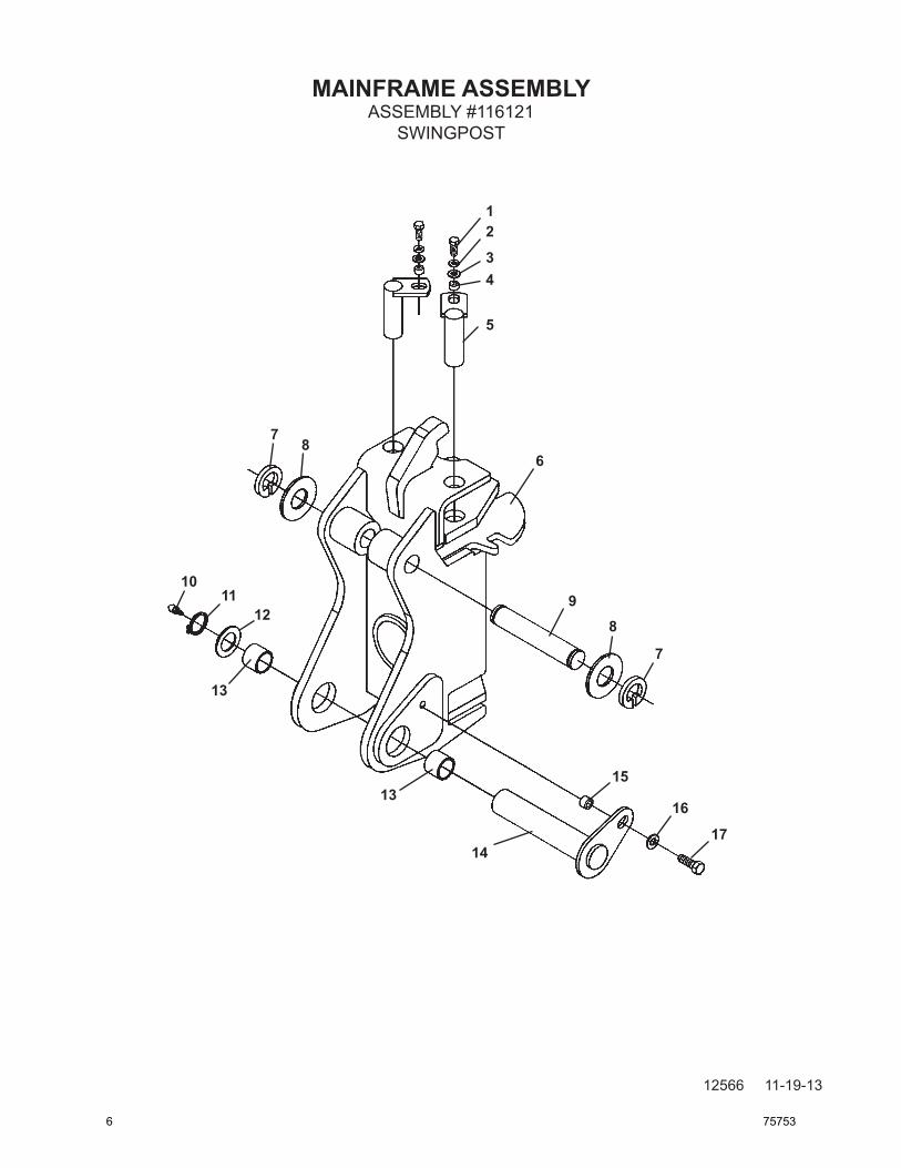
ASSEMBLY #116121SWINGPOST
12
34
5
6
9
87
8
7
1011
12
13
13
14
15
16
17
6 75753

MAINFRAME ASSEMBLY
12567 11-19-13
ITEM REQ’D PART NO. DESCRIPTION
1 2 1043 .38" UNC X 1.00" Hex Capscrew 2 2 1503 .38" Lock Washer 3 2 1514 .38" Flat Washer 4 2 81807 Spacer Tube 5 2 81847 Pin
6 1 86201 Swing Post (Includes (2) 82402 Bushings - Installed with Locktite Grade 680) 7 2 1650 Snap Ring 8 As Req'd 83975 Thrust Washer 1.38" X As Req'd 83976 Thrust Washer 1.38" X As Req'd 83977 Thrust Washer 1.38" X 9 1 86220 Pivot Pin 10 1 6616 Grease Zerk
11 1 1651 Snap Ring 12 2 6622 Thrust Washer 13 - 82402 Bushing (Included in Swing Post Assembly) (Installed with Locktite Grade 680) 14 1 86227 Pivot Pin 15 1 86149 Spacer Tube
16 1 1516 .50" Flat Washer 17 1 1088 .50" UNC X 1.00" Capscrew (Installed with Locktite Grade 680)
NOTE:(1) Pivot Pin #86220 is sold only in Pin Kit #86317. Kit includes one pin #86220, two
thrust washers #6623 and two snap rings #1650.
ASSEMBLY #116121SWINGPOST
75753 7
MAINFRAME ASSEMBLY
12568 11-19-13
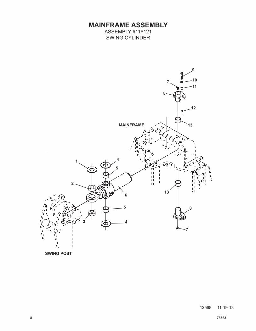
ASSEMBLY #116121SWING CYLINDER
1
2
3
4
5
6
4
5
7
8
9
1011
12
13
13
7
8
SWING POST
MAINFRAME
8 75753

MAINFRAME ASSEMBLY
12569 11-19-13
ITEM REQ’D PART NO. DESCRIPTION
1 As Req'd 57693 Thrust Washer 1.25" X .078" As Req'd 64727 Thrust Washer 1.25" X .145" As Req'd 64728 Thrust Washer 1.25" X .031" 2 - 62523 Self-Aligning Bushing (Included in Swing Cylinder Assembly) 3 2 82827 Spacer 4 4 68057 Thrust Washer 5 - 82441 Needle Bearing (Included in Swing Cylinder Assembly)
6 2 81827 Swing Cylinder Assembly (Includes (2) 82441 Needle Bearings and (1) 62523 Bushings) 2 6616 Grease Zerk 2 30164 Tee - Special Lateral Tee 7 4 53031 90° Grease Zerk 8 4 82420 Pin 9 4 1047 .38" UNC X 2.00" Hex Capscrew 10 4 1514 .38" Flat Washer
11 4 81595 Spacer Tube 12 4 1837 .38" UNC Deformed Lock Nut 13 - 83815 Bushing (Included in Mainframe - Installed with Locktite Grade 680)
ASSEMBLY #116121SWING CYLINDER
75753 9

MAINFRAME ASSEMBLY
12570 11-19-13
ASSEMBLY #116121STABILIZERS
1
1
1
1
2
2
2
2
3
3
4
5
6
2
7
10 75753

MAINFRAME ASSEMBLY
12571 11-19-13
ITEM REQ’D PART NO. DESCRIPTION
1 8 1652 Snap Ring 2 As Req'd 57693 Thrust Washer 1.25" X .078" As Req'd 64727 Thrust Washer 1.25" X .145" As Req'd 64728 Thrust Washer 1.25" X .031" 3 4 81846 Pin 4 2 86605 Stabilizer Cylinder Assembly (1.50" Rod) 4 6616 Grease Zerk 5 2 83393 Stabilzer Arm
6 2 83257 Pin 7 2 1613 Cotter Pin
NOTE:(1) Pivot Pin #81846 is sold only in Pin Kit #86314. Kit includes one pin #81846, two
thrust washers #64727 and two snap rings #1652.
ASSEMBLY #116121STABILIZERS
75753 11

HOSE BUNDLE CLAMPS
12460 9-24-13
1
2
3
3
2
1
12 75753

HOSE BUNDLE CLAMPS
12461 9-24-13
NO REQ'D PART NO. DESCRIPTION
1 2 1043 .38" UNC X 1.00" Hex Capscrew 2 1 84718 Right Hose Bundle Clamp 3 2 1837 .38" UNC Deformed Lock Nut 4 1 84718 Left Hose Bundle Clamp
75753 13
509B BOOM & DIPPER ASSEMBLY
12572 11-19-13
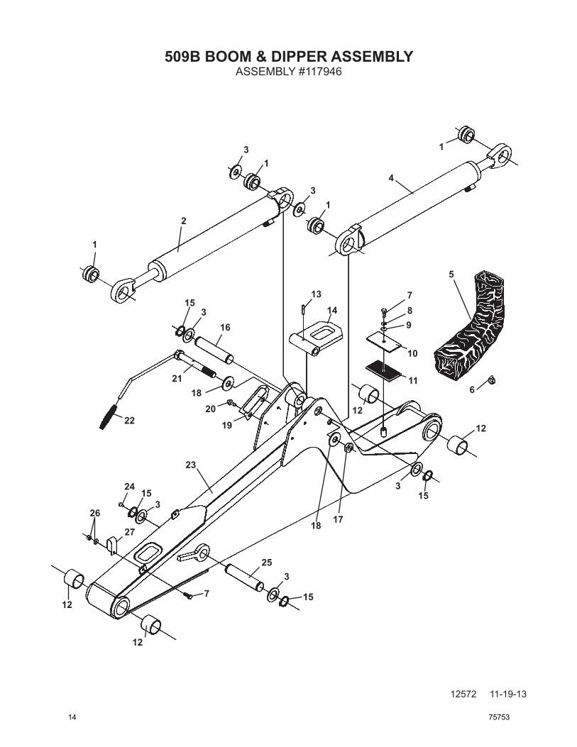
ASSEMBLY #117946
12
12
12
12
1
1
1
1
2
3
34
5
6
789
10
11
1314
315
18 17
153
16
1920
2118
22
23
24
315
26
27
253
157
14 75753

509B BOOM & DIPPER ASSEMBLY
12573 11-19-13
ITEM REQ’D PART NO. DESCRIPTION
1 - 6615 Self Aligning Bushing (Included in Cylinder Assemblies) 2 1 86236 Dipper Cylinder Assembly 2 6616 Grease Zerk 3 As Req'd 6623 Thrust Washer 1.38" x .031 As Req'd 64724 Thrust Washer 1.38" x .090 As Req'd 64725 Thrust Washer 1.38" x .125 4 1 86231 Boom Cylinder Assembly 2 6616 Grease Zerk 5 1 34120 Hose Sock 6 1 53167 Hose Clamp (Included in Console Assembly) 7 3 1043 .38" UNC X 1.00" Hex Capscrew 8 1 1503 .38" Lock Washer 9 1 1514 .38" Flat Washer 10 1 86221 Hose Clamp Plate 11 1 86222 Rubber Spacer 12 - 86673 Bushing (Included in Boom Assembly) (Installed with Locktite Grade 680) 13 1 1972 Spring Pin 14 1 86366 Boom Lock 15 4 1650 Snap Ring 16 1 86242 Pivot Pin 17 1 1959 .88" UNC Jam Nut 18 2 6562 Spring Washer 19 1 84137 Guide Plate 20 2 1961 .38" UNC X .50" Hex FlangeHead Capscrew 21 1 86230 Handle 22 1 83656 Handle Grip 23 1 86151 Boom Assembly (Includes (4) 86673 Bushings) (Installed with Locktite Grade 680) 24 1 6616 Grease Zerk 25 1 86224 Pivot Pin 26 2 1525 .38” Flat Washer 2 1837 .38" UNC Deformed Lock Nut 27 2 82859 Double Hose Clamp
NOTE: (1) Pivot Pin #86242 is sold only in Pin Kit #86315. Kit includes one pin #86242, two
thrust washers #6623 and two snap rings #1650.
(2) Pivot Pin #86224 is sold only in Pin Kit #86319. Kit includes one pin #86224, two thrust washers #6623, two snap rings #1650 and one grease zerk #6616.
ASSEMBLY #117946
(1)
(2)
75753 15

509B BOOM & DIPPER ASSEMBLYASSEMBLY #117946
12574 11-19-13
1
11
21
2
12
3
333
3
3
3
13
4
4
4
4
4
4
14
5
156
16
7
7
7
7
7
7
7
17
8
18
9
19
10
10
20
16 75753

509B BOOM & DIPPER ASSEMBLYASSEMBLY #117946
12575 11-19-13
ITEM REQ’D PART NO. DESCRIPTION
1 - 6615 Self-Aligning Bushing (Included in Cylinder Assembly) 2 1 117548 Bucket Cylinder Assembly 2 6616 Grease Zerk 3 8 1650 Snap Ring 4 As Req'd 6623 Thrust Washer 1.38" X .031 As Req'd 64724 Thrust Washer 1.38" X .090 As Req'd 64725 Thrust Washer 1.38" X .125 5 1 86226 Pivot Pin
6 1 86225 Pivot Pin 7 6 6616 Grease Zerk 8 1 1651 Snap Ring 9 As Req'd 6622 Thrust Washer 1.75 X .082 10 - 82402 Bushing (Included in Dipper Assembly) (Install with Locktite Grade 680)
11 1 86227 Pivot Pin 12 1 86149 Spacer Tube 13 1 1516 .50" Flat Washer 14 1 1090 .50" UNC X 1.50" Hex Capscrew 15 1 117947 Dipper Assembly (Includes (2) 82402 and (2) 81610 Bushings) (Installed with Locktite Grade 680)
16 1 84914 Dipper Link Plate 17 - 81610 Bushing (Included in Dipper Assembly) (Install with Locktite Grade 680) 18 1 109353 Dipper Link 19 1 109326 Bucket Link 20 1 109410 Pivot Pin
21 1 109413 Pivot Pin
NOTE:(1) Pivot Pin #86226 is sold only in Pin Kit #86318. Kit Includes one pin #86226, two thrust
washers #6623 and two snap rings #1650.
(2) Pivot Pin #86225 is sold only in Pin Kit #86316. Kit Includes one pin #86226, two thrust washers #6623 and two snap rings #1650.
(1)
(2)
75753 17

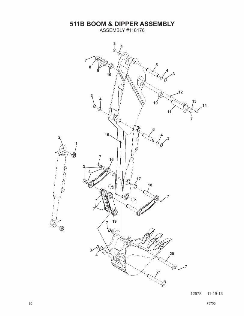
511B BOOM & DIPPER ASSEMBLY
12576 11-19-13
ASSEMBLY #118176
12
12
12
12
1
1
1
1
2
3
34
5
6
789
10
11
13 14
315
18 17
153
16
1920
2118
2223
24
315
26
2725
3
157
18 75753

511B BOOM & DIPPER ASSEMBLY
12577 11-19-13
ITEM REQ’D PART NO. DESCRIPTION
1 - 6615 Self Aligning Bushing (Included in Cylinder Assemblies) 2 1 87029 Dipper Cylinder Assembly 2 6616 Grease Zerk 3 As Req'd 6623 Thrust Washer 1.38" x .031 As Req'd 64724 Thrust Washer 1.38" x .090 As Req'd 64725 Thrust Washer 1.38" x .125 4 1 82625 Boom Cylinder Assembly 2 6616 Grease Zerk 2 3269 Straight Connector 6MJ-8MBo 5 1 34120 Hose Sock
6 1 53167 Hose Clamp (Included in Console Assembly) 7 3 1043 .38" UNC X 1.00" Hex Capscrew 8 1 1503 .38" Lock Washer 9 1 1514 .38" Flat Washer 10 1 86221 Hose Clamp Plate
11 1 86222 Rubber Spacer 12 - 86673 Bushing (Included in Boom Assembly) (Installed with Locktite Grade 680) 13 1 1972 Spring Pin 14 1 86366 Boom Lock 15 4 1650 Snap Ring
16 1 86242 Pivot Pin 17 1 1959 .88" UNC Jam Nut 18 2 6562 Spring Washer 19 1 84137 Guide Plate 20 2 1961 .38" UNC X .50" Hex FlangeHead Capscrew
21 1 86230 Handle 22 1 83656 Handle Grip 23 1 86955 Boom Assembly (Includes (4) 86673 Bushings) (Installed with Locktite Grade 680) 24 1 6616 Grease Zerk 25 1 86224 Pivot Pin
26 2 1525 .38” Flat Washer 2 1837 .38" UNC Deformed Lock Nut 27 2 82859 Double Hose Clamp
NOTE: (1) Pivot Pin #86242 is sold only in Pin Kit #86315. Kit includes one pin #86242, two thrust
washers #6623 and two snap rings #1650.
(2) Pivot Pin #86224 is sold only in Pin Kit #86319. Kit includes one pin #86224, two thrust washers #6623, two snap rings #1650 and one grease zerk #6616.
ASSEMBLY #118176
(1)
(2)
75753 19
511B BOOM & DIPPER ASSEMBLY
12578 11-19-13
ASSEMBLY #118176
1
11
2
12
3
3
3
3
3
3
13
4
4
4
4
4
4
14
5
156
16
7
7
7
7
7
7
7
17
8
18
9
19
10
10
20
21
20 75753

511B BOOM & DIPPER ASSEMBLY
12579 11-19-13
ITEM REQ’D PART NO. DESCRIPTION
1 - 6615 Self-Aligning Bushing (Included in Cylinder Assembly) 2 1 117548 Bucket Cylinder Assembly 2 6616 Grease Zerk 3 8 1650 Snap Ring 4 As Req’d 6623 Thrust Washer 1.38” X .031 As Req’d 64724 Thrust Washer 1.38” X .090 As Req’d 64725 Thrust Washer 1.38” X .125 5 1 86226 Pivot Pin
6 1 86225 Pivot Pin 7 6 6616 Grease Zerk 8 1 1651 Snap Ring 9 As Req’d 6622 Thrust Washer 1.75 X .082 10 - 82402 Bushing (Included in Dipper Assembly) (Install with Locktite Grade 680)
11 1 86227 Pivot Pin 12 1 86149 Spacer Tube 13 1 1516 .50” Flat Washer 14 1 1090 .50” UNC X 1.50” Hex Capscrew 15 1 118177 Dipper Assembly (Includes (2) 82402 and (2) 81610 Bushings) (Installed with Locktite Grade 680)
16 1 84914 Dipper Link Plate 17 - 81610 Bushing (Included in Dipper Assembly) (Install with Locktite Grade 680) 18 1 109353 Dipper Link 19 1 109326 Bucket Link 20 1 109410 Pivot Pin
21 1 109413 Pivot Pin
NOTE:(1) Pivot Pin #86226 is sold only in Pin Kit #86318. Kit Includes one pin #86226, two thrust
washers #6623 and two snap rings #1650.
(2) Pivot Pin #86225 is sold only in Pin Kit #86316. Kit Includes one pin #86226, two thrust washers #6623 and two snap rings #1650.
ASSEMBLY #118176
(1)
(2)
75753 21

CONSOLE ASSEMBLY
12472 9-24-13
ASSEMBLY #104161
1
2
34
5
6
87
23
10
11
12
13 9
18
24
2515
27
29
1719
303132
21
20
22
1415
16
26
33
28
22 75753

CONSOLE ASSEMBLY
12473 9-24-13
ITEM REQ’D PART NO. DESCRIPTION
1 2 85838 Ball Handle 2 1 87952 Right Control Handle 3 1 87951 Left Control Handle 4 1 83235 Rubber Boot 5 2 2558 M10 Hex Nut
6 1 85826 Boot Support 7 2 1001 .25” UNC X .50” Hex Capscrew 8 2 1501 .25” Lock Washer 9 6 1958 .25” UNC X .75” Hex Capscrew 10 1 106360 Console Cover with Decals
11 1 83406 Ball Handle - RED 12 1 83273 Rod 13 1 82795 Spring 14 3 1026 .31” UNC X 2.00” Hex Capscrew 15 7 1502 .31” Lock Washer
16 3 19471 Spacer Tube 17 1 101660 Valve Mounting Plate 18 2 1044 .38” UNC X 1.25” Hex Capscrew 19 1 87288 Console 20 1 1476 .38” UNF Jam Nut
21 1 5545 Balljoint 22 1 1592 .38” UNF Lock Nut 23 1 6980 Seat 24 1 87142 Seat Mounting 25 4 1513 .31” Flat Washer
26 4 1021 .31” UNC X .75” Hex Capscrew 27 2 1542 .50” UNC Nylock Nut 28 2 1516 .50” Flat Washer 29 2 1089 .50” UNC X 1.25” Hex Capscrew 30 4 1042 .38” UNC X .75” Hex Capscrew
31 4 1503 .38” Lock Washer 32 4 1514 .38” Flat Washer 33 1 87147 Cover Plate 2 1958 .25” UNC X .75” Hex Capscrew
ASSEMBLY #104161
75753 23

VALVE ASSEMBLY
12474 2-12-15-2
ASSEMBLY #2261
1
1
2
2
2
3
3
3
5
4
6
7
8
8
4
3
19
9
10
24 75753

VALVE ASSEMBLY
12475 2-12-15-2
ITEM REQ’D PART NO. DESCRIPTION
1 4 3269 Straight Connector 8MBo-6MJ 2 5 30363 90° Elbow - Long 6MJ-6FJX 3 5 3457 Straight Connector 6MBo-6MJ 4 3 30184 Straight Connector 6MBo-6MJ with .109 Restrictor 5 1 30187 Straight Connector 4FP-6FJX
6 1 3185 Needle Valve (Swing Speed Control) 7 1 3137 Straight Connector 4MP-6MJ 8 2 3104 90° Elbow 8MBo-8MJ 9 6 3430 90° Elbow 6MJ-6FJX 10 1 103546 6-Spool Monoblock Valve (Valve includes (2) 85837 stabilizer control levers and (2) 86338 control knobs)
ASSEMBLY #2261
75753 25

THIS PAGEIS INTENTIONALLY
BLANK
26 75753

VALVE ASSEMBLY
12476 9-24-13
ASSEMBLY #103546
BOOM
SWING
LEFT STABILIZER RIGHT STABILIZER
DIPPER
BUCKET
RIGHT JOYSTICK LEVER ASSEMBLY #45942
LEFT JOYSTICK LEVER ASSEMBLY #45933
STABILIZER CONTROL HANDLE #85837
STABILIZER CONTROL HANDLE #85837
STABILIZER CONTROL KNOB #86338
75753 27

VALVE ASSEMBLY
11821 4-4-13-2
VALVE ASSEMBLY #103546 SERVICE PARTS
1 23
4
5
6
5
78
9
10
11
15
14
17
18
30
20
21
22
20
33
2324
25
26
27
27
28
2918
VALVE BLOCK (NOT SOLD SEPARATELY)
22
16
15
23456
5
1013
8
9
11
12
19
31
32
28 75753

VALVE ASSEMBLY
11822 4-4-13-2
ITEM REQ’D PART NO. DESCRIPTION
1 - 45933 Joystick Lever Assembly (Left) 2 - 45932 Screw 3 - 45931 Support 4 - 45929 Pin 5 - 45927 Nut
6 - 45928 Ball Joint 7 - 45925 Support 8 - 45924 Seal 9 - 45923 Spacer 10 - 45930 Ball Joint
11 - 45926 Screw 12 - 45942 Joystick Lever Assembly (Right) 13 - 45941 Support 14 - 45935 Screw 15 - 45934 Lever Cap
16 - 45719 Main Relief (2600 PSI) 17 - 45916 Spacer 18 - 45914 O’Ring 19 - 45716 Circuit Relief Valve (2600 PSI) 20 - 45714 Anti-Cav. Circuit Relief Valve (2600 PSI)
21 - 45922 Check Valve 22 - 45921 O’Ring Plug 23 - 45918 O’Ring 24 - 45919 Spacer 25 - 45920 Spool (Float)
26 - 45730 Float Assembly 27 - 45729 Positioner Assembly 28 - 45917 Valve Spool 29 - 45915 Spacer 30 - 45935 Circuit Relief Plug
31 - 45936 Circuit Relief Valve (2900 PSI) 32 - 45937 Anti-Cav. Circuit Relief Valve (2600 PSI) 33 - 45714 Anti-Cav. Circuit Relief Valve (2900 PSI) NOT SHOWN - OPTIONAL CLOSED CENTER OR POWER BEYOND 45938 #4 BSPP Plug (Functions as Closed Center Conversion or Power Beyond. See Maintenance and Service instructions in the Operator’s manual for installation.)
VALVE ASSEMBLY #103546 SERVICE PARTS
75753 29

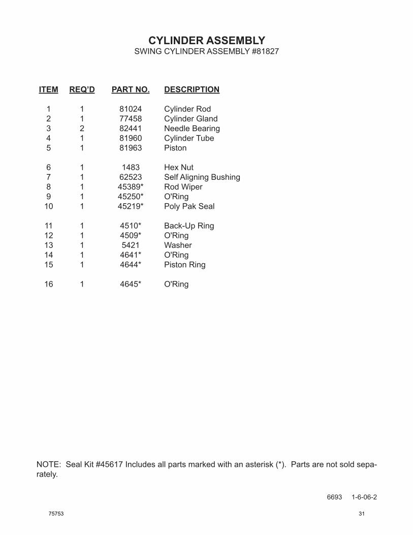
CYLINDER ASSEMBLY
6692 1-6-06-2
SWING CYLINDER ASSEMBLY #81827
1
2
3
4
5
6
7
89
10
12
11
13
14
15
16
30 75753
CYLINDER ASSEMBLY
6693 1-6-06-2
ITEM REQ’D PART NO. DESCRIPTION
1 1 81024 Cylinder Rod 2 1 77458 Cylinder Gland 3 2 82441 Needle Bearing 4 1 81960 Cylinder Tube 5 1 81963 Piston
6 1 1483 Hex Nut 7 1 62523 Self Aligning Bushing 8 1 45389* Rod Wiper 9 1 45250* O'Ring 10 1 45219* Poly Pak Seal
11 1 4510* Back-Up Ring 12 1 4509* O'Ring 13 1 5421 Washer 14 1 4641* O'Ring 15 1 4644* Piston Ring
16 1 4645* O'Ring
SWING CYLINDER ASSEMBLY #81827
NOTE: Seal Kit #45617 Includes all parts marked with an asterisk (*). Parts are not sold sepa-rately.
75753 31
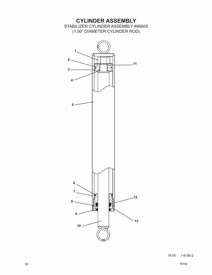
CYLINDER ASSEMBLY
7418 1-6-06-2
STABILIZER CYLINDER ASSEMBLY #86605(1.50” DIAMETER CYLINDER ROD)
1
2
3
4
5
7
6
8
9
10
11
12
13
32 75753

CYLINDER ASSEMBLY
7419 1-6-06-2
ITEM REQ’D PART NO. DESCRIPTION
1 1 1483 Hex Nut 2 1 4644* TeflonPistonRing 3 1 4645* O'Ring 4 1 4641* O'Ring 5 1 83398 CylinderTube
6 1 4509* O'Ring 7 1 4510* Back-UpRing 8 1 45250* O'Ring 9 1 45372* RodWiper 10 1 86606 CylinderRod
11 1 50252 Piston 12 1 45225* Poly-PakSeal 13 1 86609 CylinderGland
STABILIZER CYLINDER ASSEMBLY #86605(1.50” DIAMETER CYLINDER ROD)
NOTE:SealKit#45738includesallpartsmarkedwithanasterisk(*).Partsarenotsoldsepa-rately.
75753 33

CYLINDER ASSEMBLY
12479 9-24-13
BOOM CYLINDER ASSEMBLY #86231
1
2
5
6
11
12
13
14
3
4
1
8
7
9
10
34 75753

CYLINDER ASSEMBLY
12480 9-24-13
ITEM REQ’D PART NO. DESCRIPTION
1 2 6615 Self-Aligning Bushing 2 1 1483 Hex Nut 3 1 45251* TeflonPistonRing 4 1 45250* O'Ring 5 1 4641* O'Ring
6 1 86232 Cylinder Tube 7 1 45557* O'Ring 8 1 45249* Back-Up Ring 9 1 4570* O'Ring 10 1 45372* RodWiper
11 1 86234 CylinderRod 12 1 82857 Piston 13 1 45225* Poly-PakSeal 14 1 82449 Cylinder Gland
BOOM CYLINDER ASSEMBLY #86231
NOTE:SealKit#45618includesallpartsmarkedwithanasterisk(*).Partsarenotsoldsepa-rately.
75753 35

CYLINDER ASSEMBLY
12481 9-24-13
BOOM CYLINDER ASSEMBLY #82625
6
1
2
3 9
8
7
4
5
6
14
12
13
11
10
36 75753

CYLINDER ASSEMBLY
12482 9-24-13
ITEM REQ’D PART NO. DESCRIPTION
1 1 82635 Cylinder Tube 2 1 1483 Hex Nut 3 1 82793 Piston 4 1 77445 Cylinder Gland 5 1 82636 Cylinder Rod
6 2 6615 Self Aligning Bushing 7 1 4570* O'Ring 8 1 4569* Piston Ring 9 1 4641* O'Ring 10 1 45555* O'Ring
11 1 4631* Back-Up Ring 12 1 45225* Poly Pak Seal 13 1 4908* O'Ring 14 1 45372* Rod Wiper
BOOM CYLINDER ASSEMBLY #82625
NOTE: Seal Kit #45550 includes all parts marked with an asterisk (*). Parts are not sold sepa-rately.
75753 37

CYLINDER ASSEMBLY
12483 9-24-13
DIPPER CYLINDER ASSEMBLY #86236
1
2
5
6
11
12
13
14
1
3
4
8
7
9
10
38 75753

CYLINDER ASSEMBLY
12484 9-24-13
ITEM REQ’D PART NO. DESCRIPTION
1 1 6615 Self-Aligning Bushing 2 1 1484 Hex Nut 3 1 4569* TeflonPistonRing 4 1 4570* O'Ring 5 1 4865* O'Ring
6 1 86237 Cylinder Tube 7 1 45555* O'Ring 8 1 4631* Back-Up Ring 9 1 4908* O'Ring 10 1 45370* RodWiper
11 1 82626 CylinderRod 12 1 86241 Piston 13 1 45119* Poly-PakSeal 14 1 77443 Cylinder Gland
DIPPER CYLINDER ASSEMBLY #86236
NOTE:SealKit#45684includesallpartsmarkedwithanasterisk(*).Partsarenotsoldsepa-rately.
75753 39

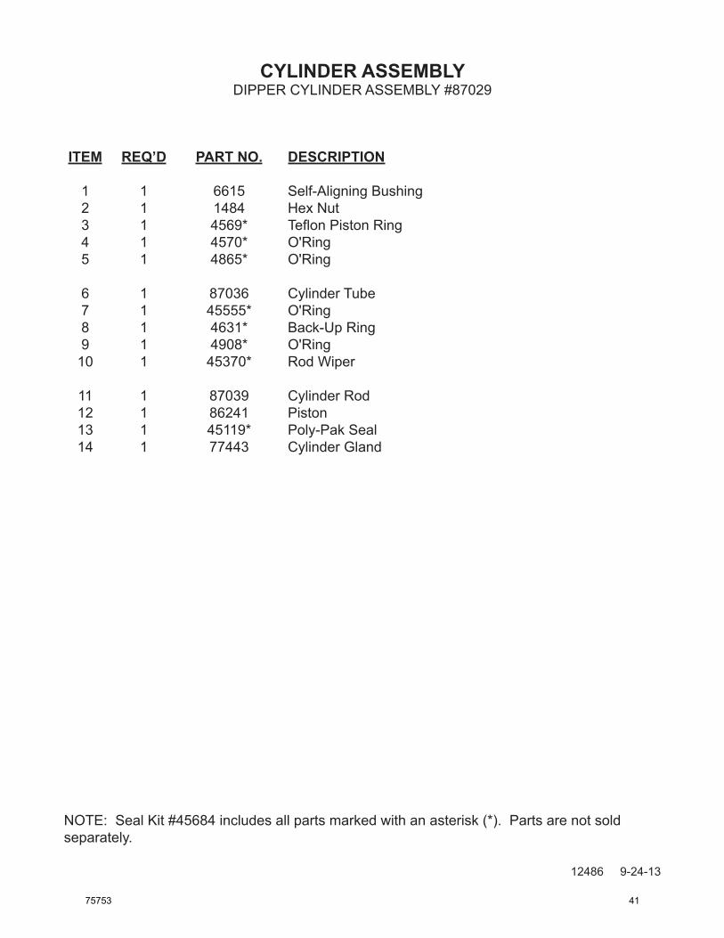
CYLINDER ASSEMBLY
12485 9-24-13
DIPPER CYLINDER ASSEMBLY #87029
1
2
5
6
11
12
13
14
1
3
4
8
7
9
10
40 75753
CYLINDER ASSEMBLY
12486 9-24-13
ITEM REQ’D PART NO. DESCRIPTION
1 1 6615 Self-Aligning Bushing 2 1 1484 Hex Nut 3 1 4569* TeflonPistonRing 4 1 4570* O'Ring 5 1 4865* O'Ring
6 1 87036 Cylinder Tube 7 1 45555* O'Ring 8 1 4631* Back-Up Ring 9 1 4908* O'Ring 10 1 45370* RodWiper
11 1 87039 CylinderRod 12 1 86241 Piston 13 1 45119* Poly-PakSeal 14 1 77443 Cylinder Gland
DIPPER CYLINDER ASSEMBLY #87029
NOTE:SealKit#45684includesallpartsmarkedwithanasterisk(*).Partsarenotsoldseparately.
75753 41

CYLINDER ASSEMBLY
12613 12-2-13
BUCKET CYLINDER ASSEMBLY #117548
2
3
4
1
6
7
8
9
5
6
11
10
14
1312
42 75753

CYLINDER ASSEMBLY
12614 12-2-13
ITEM REQ’D PART NO. DESCRIPTION
1 1 117549 Cylinder Tube (See Note) 2 1 1484 Hex Nut 3 1 55904 Piston 4 1 77444 Cylinder Gland 5 1 82506 Cylinder Rod
6 2 6615 Self Aligning Bushing 7 1 4570* O'Ring 8 1 4569* Piston Ring 9 1 4865* O'Ring 10 1 45555* O'Ring
11 1 4631* Back-Up Ring 12 1 45117* Poly Pak Seal 13 1 4908* O'Ring 14 1 45364* Rod Wiper
BUCKET CYLINDER ASSEMBLY #117548
NOTE: Seal Kit #45547 includes all parts marked with an asterisk (*). Parts are not sold separately.
75753 43
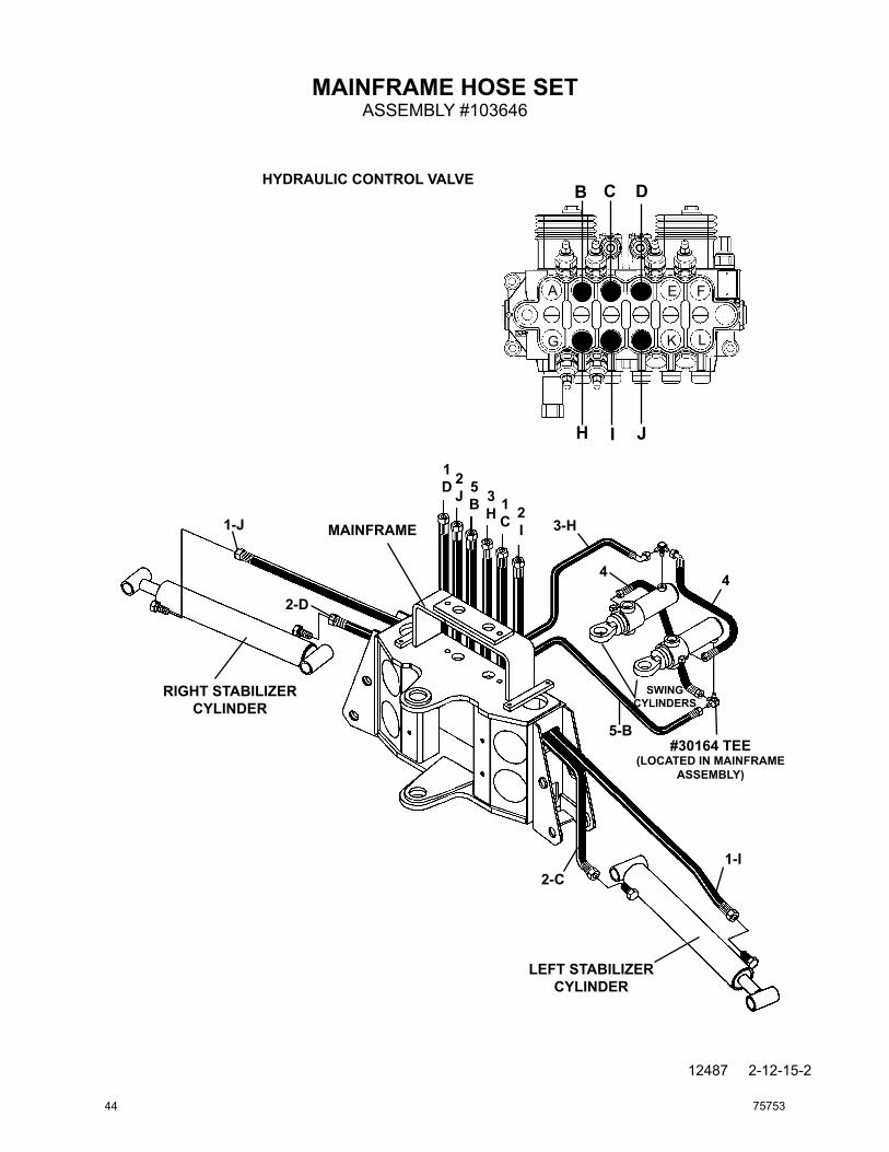
MAINFRAME HOSE SET
12487 2-12-15-2
ASSEMBLY #103646
1D 2
J 5B 3
H 1C 2
I
2-D
1-J
5-B
3-H
1-I2-C
4 4
#30164 TEE(LOCATED IN MAINFRAME
ASSEMBLY)
RIGHT STABILIZER CYLINDER
SWING CYLINDERS
MAINFRAME
LEFT STABILIZER CYLINDER
HYDRAULIC CONTROL VALVE
H JI
B C D
A E F
G K L
44 75753

MAINFRAME HOSE SET
12488 2-12-15-2
ITEM REQ’D PART NO. DESCRIPTION
1 2 37579 Hose Assembly .25" X 51" 6FJX-6FJX
2 2 37580 Hose Assembly .25" X 54" 6FJX-6FJX
3 1 37700 Hose Assembly .25" X 13.50" 6FJX-6FJX 90° Gooseneck
4 2 37552 Hose Assembly .25" X 14.50" 6FJX-6FJX
5 1 37699 Hose Assembly .25" X 17" 6FJX-6FJX
ASSEMBLY #103646
NOTE: Letters on the hose set diagram show the hydaulic hose routing between the backhoe control valve and the various hydraulic cylinders. Simply match the letter on the control valve port to the same letter on the hydraulic hose ends. Example: Hose Assembly labeled "C" runs from the upper Left Stabilizer port on the hydraulic control valve - through the mainframe and to the barrel end fitting on the left stabilizer cylinder.
NOTE: The fittings on the hydraulic cylinders have been altered for clarity purposes. This will assist you in distinguishing between the rod end and the barrel end of the various hydraulic cylinders.
NOTE: Refer to the mainframe assembly for the priority valve hoses which are included in this assembly but have been shown in the mainframe assembly for clarity.
75753 45

509B BOOM & DIPPER HOSE SET
12581 11-20-13
ASSEMBLY #85448
CB D
H I J
A E
LKG
F
2-E
2-K
1-G
1-A
3-L
3-F
3L
3F
2K
2E
1G
1A
HYDRAULIC CONTROL VALVE
DIPPER CYLINDER
BOOM CYLINDER
DIPPER
BUCKET CYLINDER
BOOM(CUTAWAY VIEW)
SWING POST
MAINFRAME
46 75753

509B BOOM & DIPPER HOSE SET
12582 11-20-13
ITEM REQ’D PART NO. DESCRIPTION
1 2 37671 Hose Assembly .38" X 93" 6FJX - 6FJX
2 2 38761 Hose Assembly .38" X 146.00" 6FJX - 8FJX
3 2 37672 Hose Assembly .38" X 135" 6FJX - 6FJX
ASSEMBLY #85448
NOTE: Letters on the hose set diagram show the hydraulic hose routing between the back-hoe control valve and the various hydraulic cylinders. Simply match the letter on the control valve port to the same letter on the hydraulic hose ends. EXAMPLE: Hose Assemby labeled "G" runs from the lower Boom port of the hydraulic control valve - through the mainframe and swing post and to the barrel end of the boom cylinder.
NOTE: The fittings on the hydraulic cylinders have been altered for clarity purposes. This will assist you in distinguishing between the rod end and the barrel end of the various hydraulic cylinders.
75753 47

511B BOOM & DIPPER HOSE SET
12582 11-20-13
ASSEMBLY #86982
CB D
H I J
A E
LKG
F
3-E
3-K
1-G
1-A
2-L
2-F
2L
2F
3K
3E
1G
1A
HYDRAULIC CONTROL VALVE
DIPPER CYLINDER
BOOM CYLINDER
DIPPER
BUCKET CYLINDER
BOOM(CUTAWAY VIEW)
SWING POST
MAINFRAME
48 75753

511B BOOM & DIPPER HOSE SET
12583 1-20-13
ITEM REQ’D PART NO. DESCRIPTION
1 2 37671 Hose Assembly .38" X 93" 6FJX - 6FJX
2 2 37701 Hose Assembly .38" X 157.50" 6FJX - 6FJX
3 2 38762 Hose Assembly .38” X 165.00” 6FJX - 8FJX
ASSEMBLY #86982
NOTE: Letters on the hose set diagram show the hydraulic hose routing between the back-hoe control valve and the various hydraulic cylinders. Simply match the letter on the control valve port to the same letter on the hydraulic hose ends. EXAMPLE: Hose Assemby labeled "G" runs from the lower Boom port of the hydraulic control valve - through the mainframe and swing post and to the barrel end of the boom cylinder.
NOTE: The fittings on the hydraulic cylinders have been altered for clarity purposes. This will assist you in distinguishing between the rod end and the barrel end of the various hydraulic cylinders.
75753 49
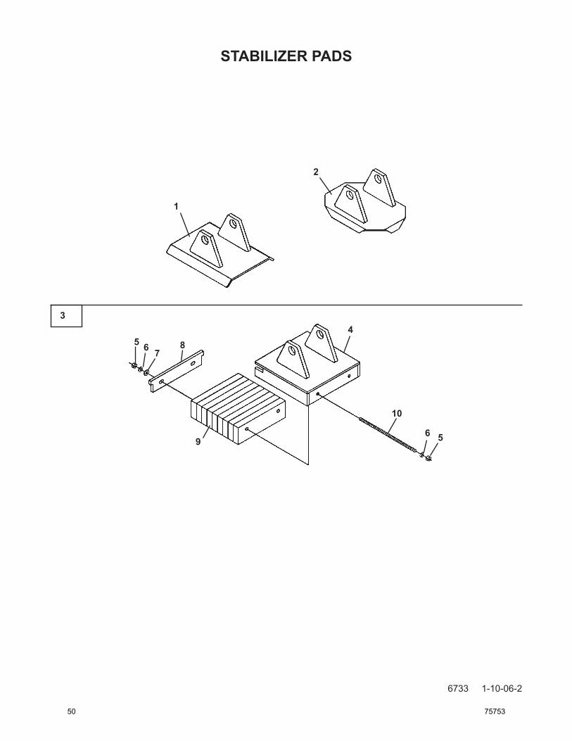
STABILIZER PADS
6733 1-10-06-2
1
2
34
5 6 78
569
10
50 75753

STABILIZER PADS
6734 1-10-06-2
ITEM REQ’D PART NO. DESCRIPTION
FLAT STABILIZER PAD ASSEMBLY - #81861
1 2 81865 Flat Stabilizer Pad
GROUSER STABILIZER PAD ASSEMBLY - #81860
2 2 83421 Grouser Stabilizer Pad
RUBBER STABILIZER PAD ASSEMBLY - #81862
3 2 83418 Rubber Stabilizer Pad Assembly (Includes Items 4 through 10)
4 1 83419 Stabilizer Pad 5 4 1226 .38" UNC Hex Nut 6 4 1503 .38" Lock Washer 7 2 1514 .38" Flat Washer 8 1 51190 Slide Plate 9 1 64412 Rubber Strip Bundle 10 2 1661 .38" UNC X 11.50" Readi Bolt
75753 51

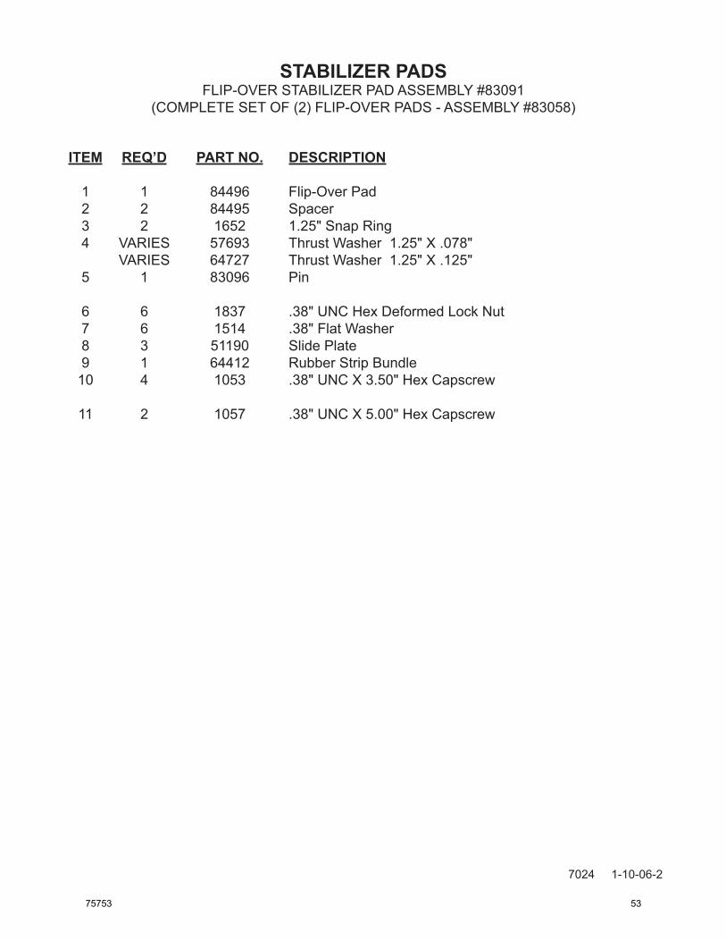
STABILIZER PADS
7023 1-10-06-2
FLIP-OVER STABILIZER PAD ASSEMBLY #83091(COMPLETE SET OF (2) FLIP-OVER PADS - ASSEMBLY #83058)
1
2
3
4
5
34
67
678
88
9 9
9
10 11
52 75753
STABILIZER PADS
7024 1-10-06-2
ITEM REQ’D PART NO. DESCRIPTION
1 1 84496 Flip-Over Pad 2 2 84495 Spacer 3 2 1652 1.25" Snap Ring 4 VARIES 57693 Thrust Washer 1.25" X .078" VARIES 64727 Thrust Washer 1.25" X .125" 5 1 83096 Pin
6 6 1837 .38" UNC Hex Deformed Lock Nut 7 6 1514 .38" Flat Washer 8 3 51190 Slide Plate 9 1 64412 Rubber Strip Bundle 10 4 1053 .38" UNC X 3.50" Hex Capscrew
11 2 1057 .38" UNC X 5.00" Hex Capscrew
FLIP-OVER STABILIZER PAD ASSEMBLY #83091(COMPLETE SET OF (2) FLIP-OVER PADS - ASSEMBLY #83058)
75753 53

OPTIONAL STABILIZER CYLINDER COVER
7449 1-10-06-2
ASSEMBLY #86706
3
3
2
1
4
5
5
54 75753

OPTIONAL STABILIZER CYLINDER COVER
7450 1-10-06-2
ITEM REQ’D PART NO. DESCRIPTION
1 2 83915 Stabilizer Cylinder Cover with Decal 2 2 4167 No Step Decal 3 2 83906 1.50" Clamp Assembly 4 2 83911 Guide Ring 5 4 1575 .38" UNC X .50" Set Screw
ASSEMBLY #86706
75753 55

BUCKET ASSEMBLIES
11336 1-13-09
1
2
34
5
56 75753

BUCKET ASSEMBLIES
11337 11-20-13-2
ITEM REQ’D PART NO. DESCRIPTION
1 - 110012 12” Bucket (Includes Teeth and Bushings) 110016 16” Bucket (Includes Teeth and Bushings) 110018 18” Bucket (Includes Teeth and Bushings) 110020 20” Bucket (Includes Teeth and Bushings) 110024 24” Bucket (Includes Teeth and Bushings) 110034 34” Bucket (Includes Teeth and Bushings) 110036 36” Bucket (Includes Teeth and Bushings) 110038 38” Bucket (Includes Teeth and Bushings) 2 8 6355 Replacement Bushing 3 Varies 74228* Replacement Tooth Shank (Weld On) 4 Varies 74227* Replacement Spiral Roll Pin 5 Varies 84863* Replacement Tooth (Bolt On)
BUCKET SPECIFICATIONSBUCKET SIZE TOOTH QTY WEIGHT STRUCK CAPACITY RATED CAPACITY
12 3 125 LBS. 1.25 CU. FT. 1.53 CU. FT.16 4 148 LBS. 1.72 CU. FT. 2.20 CU. FT.18 4 156 LBS. 1.95 CU. FT. 2.54 CU. FT.20 4 165 LBS. 2.16 CU. FT. 2.81 CU. FT.24 4 180 LBS. 2.65 CU. FT. 3.57 CU. FT.34 7 238 LBS. 3.82 CU. FT. 5.31 CU. FT.36 7 246 LBS. 4.05 CU. FT. 5.56 CU. FT. 38 7 255 LBS. 1.28 CU. FT. 5.99 CU. FT.
NOTE: Tooth and Shank Assembly #85003 includes one each of all parts marked with an asterisk (*).
75753 57

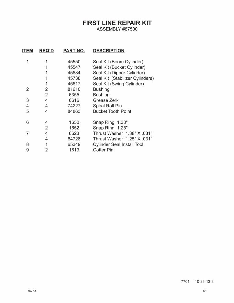
FIRST LINE REPAIR KIT
7368 10-23-13-4
ASSEMBLY #86320
1
2
3
4
5
6
78
9
58 75753

FIRST LINE REPAIR KIT
7369 10-23-13-4
ITEM REQ’D PART NO. DESCRIPTION
1 1 45618 Seal Kit (Boom Cylinder) 1 45547 Seal Kit (Bucket Cylinder) 1 45684 Seal Kit (Dipper Cylinder) 1 45738 Seal Kit (Stabilizer Cylinders) 1 45617 Seal Kit (Swing Cylinder) 2 2 81610 Bushing 2 6355 Bushing 3 4 6616 Grease Zerk 5 4 74227 Spiral Roll Pin 4 84863 Bucket Tooth Point
6 4 1650 Snap Ring 1.38" 2 1652 Snap Ring 1.25" 7 4 6623 Thrust Washer 1.38" X .031" 4 64728 Thrust Washer 1.25" X .031" 8 1 65349 Cylinder Seal Install Tool 9 2 1613 Cotter Pin
ASSEMBLY #86320
75753 59

FIRST LINE REPAIR KIT
7700 10-23-13-3
ASSEMBLY #87500
1
2
35
4
6
78
9
60 75753
FIRST LINE REPAIR KIT
7701 10-23-13-3
ITEM REQ’D PART NO. DESCRIPTION
1 1 45550 Seal Kit (Boom Cylinder) 1 45547 Seal Kit (Bucket Cylinder) 1 45684 Seal Kit (Dipper Cylinder) 1 45738 Seal Kit (Stabilizer Cylinders) 1 45617 Seal Kit (Swing Cylinder) 2 2 81610 Bushing 2 6355 Bushing 3 4 6616 Grease Zerk 4 4 74227 Spiral Roll Pin 5 4 84863 Bucket Tooth Point
6 4 1650 Snap Ring 1.38" 2 1652 Snap Ring 1.25" 7 4 6623 Thrust Washer 1.38" X .031" 4 64728 Thrust Washer 1.25" X .031" 8 1 65349 Cylinder Seal Install Tool 9 2 1613 Cotter Pin
ASSEMBLY #87500
75753 61

DECALS
12493 9-26-13
DECAL PLACEMENTGENERAL INFORMATION The diagrams on this page shows the location of all the decals used on the backhoes. The decals are identified by their part numbers, with reductions of the actual decals located on the following pages. Use this information to order replacements for lost or damaged decals. Be sure to read all decals before operating the backhoe. They contain information you need to know for both safety and backhoe longevity.
40151
40255
4247
40257
436840091
41169
LOGO
40219(LOCATED ON RIGHT
SIDE OF BOOM)
MODEL NUMBER
4271(LOCATED ON BACK
OF CONSOLE)
4338
SERIAL NUMBER TAG
4140
408440149
40249
408440440
IMPORTANT: Keep all safety decals clean and legible. Replace all missing, illegible or damaged safety decals. When replacing parts with safety decals attached, the safety decals must also be replaced.
REPLACING SAFETY DECALS: Clean the area of application with a nonflammable solvent, then wash the same area with soap and water. Allow the surface to dry. Remove the backing from the safety decal, exposing the adhe-sive surface. Apply the safety decal to the position shown in the diagram, and smooth out any bubbles.
62 75753

DECALS
12621 12-9-13
PART #4368 OPERATING CONTROLS DECAL
PART #4247SWING SPEED CONTROL DECAL
PART #40219 PART #40249BOOM LOCK DECAL SWING LOCK DECAL
PART #4271INLINE FILTER DECAL
PART #40091FLOAT DECAL
NOTE: CONTACT PALADIN OR YOUR LOCAL DEALER FOR MODEL NUMBER AND LOGO DECALS.
75753 63

DECALS
6789 4-20-11-4
PART #4140BUCKET CONTACT WARNING DECAL
PART #40440CALL BEFORE YOU DIG
PART #4084GREASE 8 HOURS
PART #4338MADE IN U.S.A. DECAL
64 75753

DECALS
6790 7-6-10-4
PART #40151HIGH PRESSURE FLUID DECAL
IMPORTANTTO PREVENT BACKHOE DAMAGE:
DO NOT ATTACH TOW CHAIN TO DIPPER OR BUCKET.
DO NOT REPEATEDLY SLAM SWING POST INTO SWING STOPS.
PREPARATIONFOR STORAGE
LUBRICATE ALL GREASE POINTS. LEAVE AS MANY CYLINDERS IN CLOSED POSITION AS POSSIBLE. COVER ALL EXPOSED CYLINDER RODS WITH A LIGHT COAT OF GREASE. #40257
WARNINGTO PREVENT SERIOUS INJURY
OR DEATH: Do not operate or work on this machine with-
out reading and understanding Operator's Manual.
Avoid unsafe operation or maintenance. Do not operate machine with guards and
covers removed. This machine was designed to be operated
by one operator. Do not carry passengers on unit.
Before installing backhoe on your unit extend boom and dipperstick and lower
bucket to ground. Never use backhoe as manlift. Operate backhoe control levers from opera-
tor's seat only. Lower stabilizers and bucket to ground before leaving operator's seat.
Engage boom lock and swing lock before transporting backhoe.
#40255
PART #40257IMPORTANT! DECAL
PART #40149DANGER! PINCH POINTS
PART #41169DANGER! BACKHOE SECURE
PART #40255OPERATIONAL WARNING DECAL
75753 65