parts manual -0411172491 to present · 5 tank and door assembly v500 021017-e vacassy031 item qty...
TRANSCRIPT
© 2017 by McLaughlin Group, Inc. 021717
All rights reserved. No part of this manual may be reproduced in any form, or by any means
without prior written permission of McLaughlin Group, Inc.
2006 Perimeter Road. Greenville, SC 29605Toll Free: 800/435-9340 - Phone: 864/277-5870
Fax: 864/235-9661 - Website address: www.mclaughlinunderground.comEmail address: [email protected]
Parts ManualVermeer/ McLaughlin
VX25-500G VX25-800GVX25-1200G
Vacuum Machine(Serial # 0411172491 - PRESENT)

Table of Contents
PARTSSPOIL TANK AND FILTRATION
MANUAL/HYDRAULIC DOOR ............................................................... 4HYDRAULIC DOOR CYLNDER ................................................................. 10FILTRATION ............................................................................................. 12
ENGINE COMPARTMENTENGINE .................................................................................................. 14BLOWER ............................................................................................. 16ELECTRICAL ......................................................................................... 22HYDRAULIC PUMP ................................................................................ 26
TRAILER AND SKID ASSEMBLY SKID ASSEMBLY ....................................................................................... 30
TRAILER ................................................................................................. 36TOOLS
SUCTION TOOL. .................................................................................... 42HOSES .............................................................................................. 44
HYDRAULIC SCHEMATICSBOOM 12V HYDRAULIC ........................................................................... 47
ELECTRICAL SCHEMATICSENGINE .............................................................................................. 49
MAINTENANCE MANUALSROOTS BLOWER ................................................................................... 51
WARRANTY
4
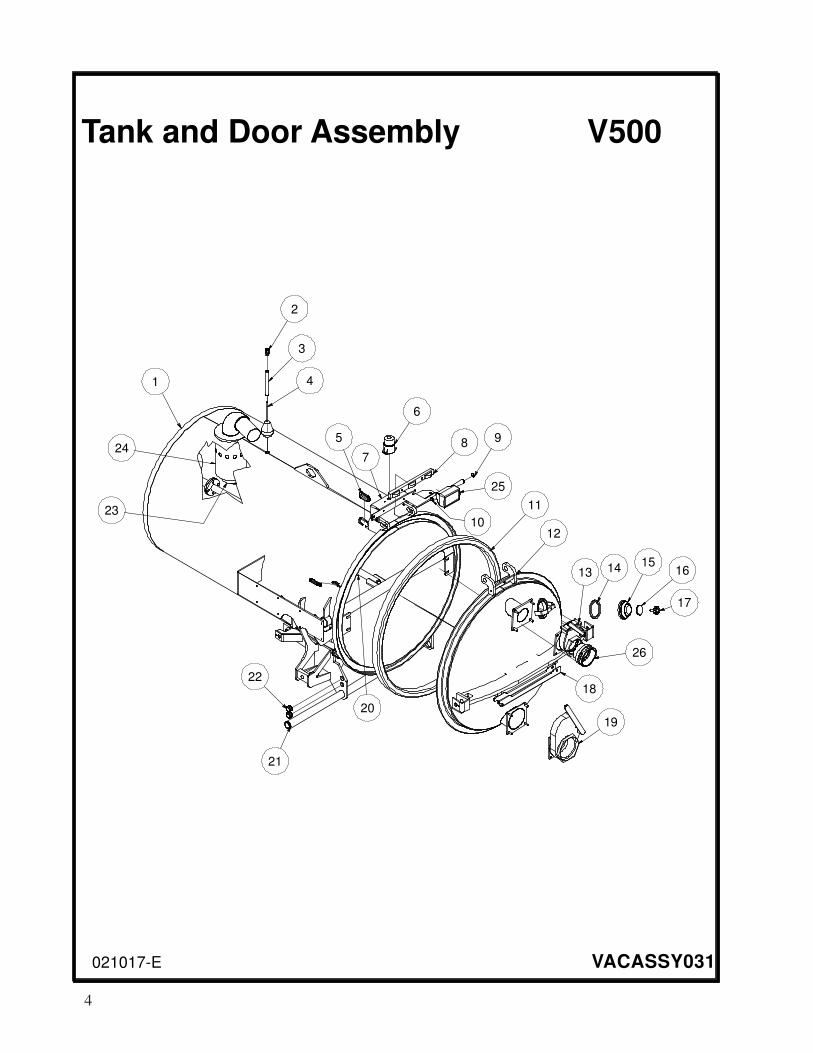
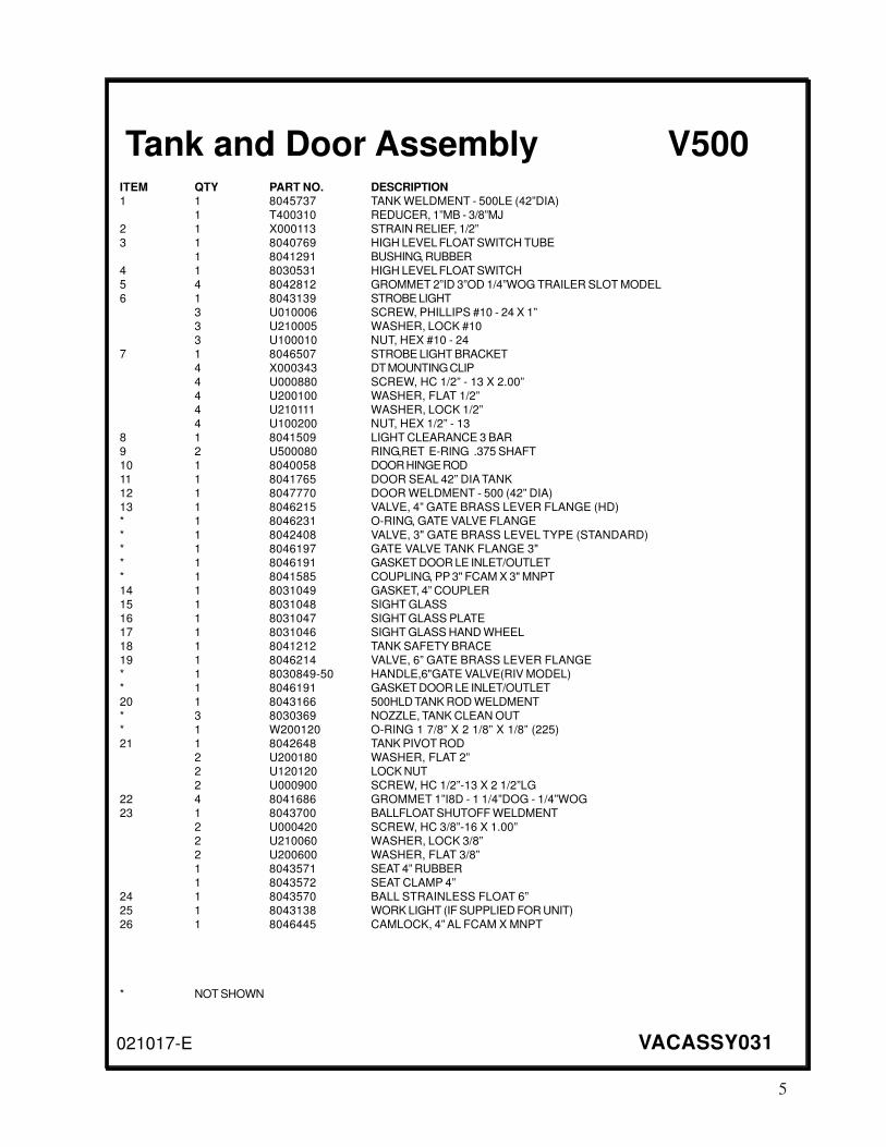
Tank and Door Assembly V500
021017-E VACASSY031
1
2
3
4
5
6
89
10
11
12
13 1415
16
17
18
19
20
21
22
23
247
25
26
5
V500Tank and Door Assembly
021017-E VACASSY031
ITEM QTY PART NO. DESCRIPTION1 1 8045737 TANK WELDMENT - 500LE (42”DIA)
1 T400310 REDUCER, 1”MB - 3/8”MJ
2 1 X000113 STRAIN RELIEF, 1/2”
3 1 8040769 HIGH LEVEL FLOAT SWITCH TUBE
1 8041291 BUSHING, RUBBER
4 1 8030531 HIGH LEVEL FLOAT SWITCH
5 4 8042812 GROMMET 2”ID 3”OD 1/4”WOG TRAILER SLOT MODEL
6 1 8043139 STROBE LIGHT
3 U010006 SCREW, PHILLIPS #10 - 24 X 1”
3 U210005 WASHER, LOCK #10
3 U100010 NUT, HEX #10 - 24
7 1 8046507 STROBE LIGHT BRACKET
4 X000343 DT MOUNTING CLIP
4 U000880 SCREW, HC 1/2” - 13 X 2.00”
4 U200100 WASHER, FLAT 1/2”
4 U210111 WASHER, LOCK 1/2”
4 U100200 NUT, HEX 1/2” - 13
8 1 8041509 LIGHT CLEARANCE 3 BAR
9 2 U500080 RING,RET E-RING .375 SHAFT
10 1 8040058 DOOR HINGE ROD
11 1 8041765 DOOR SEAL 42” DIA TANK
12 1 8047770 DOOR WELDMENT - 500 (42” DIA)
13 1 8046215 VALVE, 4” GATE BRASS LEVER FLANGE (HD)
* 1 8046231 O-RING, GATE VALVE FLANGE
* 1 8042408 VALVE, 3" GATE BRASS LEVEL TYPE (STANDARD)
* 1 8046197 GATE VALVE TANK FLANGE 3"
* 1 8046191 GASKET DOOR LE INLET/OUTLET
* 1 8041585 COUPLING, PP 3" FCAM X 3" MNPT
14 1 8031049 GASKET, 4” COUPLER
15 1 8031048 SIGHT GLASS
16 1 8031047 SIGHT GLASS PLATE
17 1 8031046 SIGHT GLASS HAND WHEEL
18 1 8041212 TANK SAFETY BRACE
19 1 8046214 VALVE, 6” GATE BRASS LEVER FLANGE
* 1 8030849-50 HANDLE,6"GATE VALVE(RIV MODEL)
* 1 8046191 GASKET DOOR LE INLET/OUTLET
20 1 8043166 500HLD TANK ROD WELDMENT
* 3 8030369 NOZZLE, TANK CLEAN OUT
* 1 W200120 O-RING 1 7/8” X 2 1/8” X 1/8” (225)
21 1 8042648 TANK PIVOT ROD
2 U200180 WASHER, FLAT 2”
2 U120120 LOCK NUT
2 U000900 SCREW, HC 1/2”-13 X 2 1/2”LG
22 4 8041686 GROMMET 1”I8D - 1 1/4”DOG - 1/4”WOG
23 1 8043700 BALLFLOAT SHUTOFF WELDMENT
2 U000420 SCREW, HC 3/8”-16 X 1.00”
2 U210060 WASHER, LOCK 3/8”
2 U200600 WASHER, FLAT 3/8”
1 8043571 SEAT 4” RUBBER
1 8043572 SEAT CLAMP 4”
24 1 8043570 BALL STRAINLESS FLOAT 6”
25 1 8043138 WORK LIGHT (IF SUPPLIED FOR UNIT)
26 1 8046445 CAMLOCK, 4” AL FCAM X MNPT
* NOT SHOWN
6
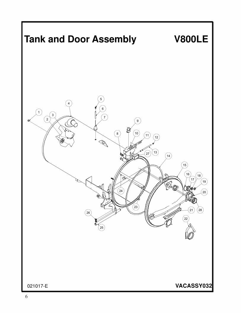
Tank and Door Assembly V800LE
021017-E VACASSY032
1
2
3
5
6
7
9
1112
13
8
14
15
16
17
18
19
20
22
21
24
23
4
25
26
10
27
28

7
V800LETank and Door Assembly
021017-E VACASSY032
ITEM QTY PART NO. DESCRIPTION1 1 T400310 REDUCER, 1”MB - 3/8”MJ
2 1 8043570 BALL STAINLESS FLOAT 6”
3 1 8043700 BALL FLOAT SHUTOFF WELDMENT
2 U000420 SCREW, HC 3/8”-16 X 1.00”
2 U210060 WASHER, LOCK 3/8”
2 U200600 WASHER, FLAT 3/8”
1 8043571 SEAT 4” RUBBER
1 8043572 SEAT CLAMP 4”
4 1 8046150 TANK WELDMENT - 800LE (48”DIA)
5 1 X000113 STRAIN RELIEF, 1/2”
6 1 8040769 HIGH LEVEL FLOAT SWITCH TUBE
7 1 8030531 HIGH LEVEL FLOAT SWITCH
8 4 8042812 GROMMET 2”ID3”OD1/4” WOG TRAILER SLOT MODEL
9 1 8043139 STROBE LIGHT
3 U010006 SCREW, PHILLIPS #10-24 X 1”
3 U210005 WASHER, FLAT 1/2”
3 U100010 NUT HEX, #10 - 24
10 1 8046507 STROBE LIGHT BRACKET WELDMENT
4 X000343 DT MOUNTING CLIP
4 U000880 SCREW, HC 1/2”-13 X 2.00”
4 U200100 WASHER, FLAT 1/2”
4 U210111 WASHER, LOCK 1/2”
4 U100200 NUT, HEX 1/2” - 13
11 1 8041509 LIGHT CLEARANCE 3 BAR
12 2 U500020 SNAP RING, EXT 1" SHAFT ZP
13 1 8040058 DOOR HINGE ROD
14 1 8041766 SEAL, DOOR SQ V750/V800LE 154"
15 1 8047771 DOOR 800 (48”)- WELDMENT
16 1 8031049 GASKET, 4” COUPLER
17 1 8031048 SIGHT GLASS
18 1 8031047 SIGHT GLASS PLATE
19 1 8031046 SIGHT GLASS HAND WHEEL
20 1 8046215 VALVE, 4” GATE BRASS LEVER FLANGE (HD)
* 1 8046231 O-RING, GATE VALVE FLANGE
* 1 8042408 VALVE, 3” GATE BRASS LEVER TYPE (STANDARD)
* 1 8046197 GATE VALVE TANK FLANGE 3”
* 1 8046191 GASKET DOOR LE INLET/OUTLET
* 1 8041585 COUPLING, PP 3" FCAM X 3" MNPT
21 1 8041212 TANK SAFETY BRACE
22 1 8046214 VALVE 6” GATE BRASS LEVER
1 8030849-50 HANDLE,6"GATE VALVE(RIV MODEL)
1 8046191 GASKET DOOR LE INLET/OUTLET
23 1 8046172 TANK ROD 800LE WELDMENT
* 1 W200120 O-RING, 1 7/8” X 2 1/8” X 1/8” (225)
24 3 8030369 NOZZLE, TANK CLEANOUT
25 1 8042648 TANK PIVOT ROD
2 U200180 WASHER FLAT 2”
2 U120120 LOCK NUT
2 U000900 SCREW, HC 1/2” - 13 X 2 1/2”LG
26 4 8041686 GROMMET 1”ID- 1 1/4”DOG - 1/4”WO
27 1 8043138 WORK LIGHT (IF SUPPLIED FOR UNIT)
28 1 8046445 CAMLOCK, 4” AL FCAM X MNPT
* NOT SHOWN
8
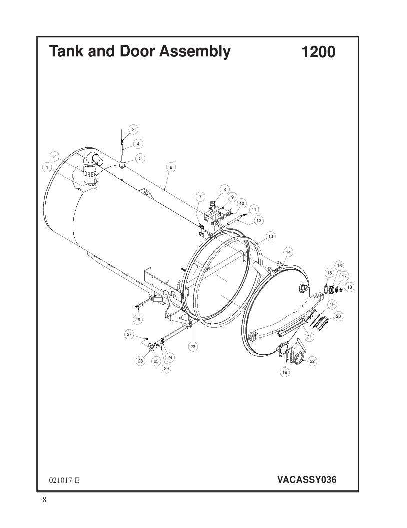
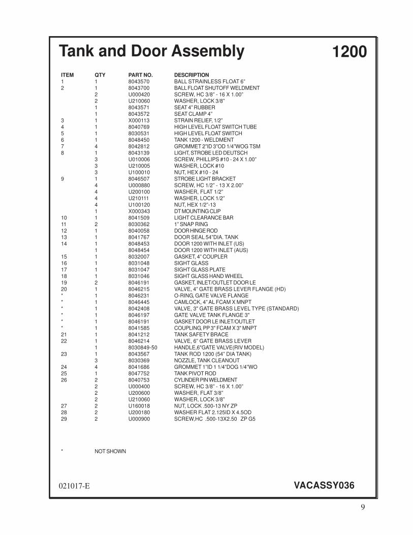
Tank and Door Assembly 1200
021017-E VACASSY036
6
3
4
5
8
9
10
11
12
7
13
14
15
16
17
18
19
20
22
21
19
2524
23
26
2
1
29
28
27
9
021017-E VACASSY036
ITEM QTY PART NO. DESCRIPTION1 1 8043570 BALL STRAINLESS FLOAT 6”
2 1 8043700 BALL FLOAT SHUTOFF WELDMENT
2 U000420 SCREW, HC 3/8” - 16 X 1.00”
2 U210060 WASHER, LOCK 3/8”
1 8043571 SEAT 4” RUBBER
1 8043572 SEAT CLAMP 4”
3 1 X000113 STRAIN RELIEF, 1/2”
4 1 8040769 HIGH LEVEL FLOAT SWITCH TUBE
5 1 8030531 HIGH LEVEL FLOAT SWITCH
6 1 8048450 TANK 1200 - WELDMENT
7 4 8042812 GROMMET 2”ID 3”OD 1/4”WOG TSM
8 1 8043139 LIGHT, STROBE LED DEUTSCH
3 U010006 SCREW, PHILLIPS #10 - 24 X 1.00”
3 U210005 WASHER, LOCK #10
3 U100010 NUT, HEX #10 - 24
9 1 8046507 STROBE LIGHT BRACKET
4 U000880 SCREW, HC 1/2” - 13 X 2.00”
4 U200100 WASHER, FLAT 1/2”
4 U210111 WASHER, LOCK 1/2”
4 U100120 NUT, HEX 1/2”-13
1 X000343 DT MOUNTING CLIP
10 1 8041509 LIGHT CLEARANCE BAR
11 2 8030362 1” SNAP RING
12 1 8040058 DOOR HINGE ROD
13 1 8041767 DOOR SEAL 54”DIA. TANK
14 1 8048453 DOOR 1200 WITH INLET (US)
1 8048454 DOOR 1200 WITH INLET (AUS)
15 1 8032007 GASKET, 4” COUPLER
16 1 8031048 SIGHT GLASS
17 1 8031047 SIGHT GLASS PLATE
18 1 8031046 SIGHT GLASS HAND WHEEL
19 2 8046191 GASKET, INLET/OUTLET DOOR LE
20 1 8046215 VALVE, 4” GATE BRASS LEVER FLANGE (HD)
* 1 8046231 O-RING, GATE VALVE FLANGE
* 1 8046445 CAMLOCK, 4” AL FCAM X MNPT
* 1 8042408 VALVE, 3" GATE BRASS LEVEL TYPE (STANDARD)
* 1 8046197 GATE VALVE TANK FLANGE 3"
* 1 8046191 GASKET DOOR LE INLET/OUTLET
* 1 8041585 COUPLING, PP 3" FCAM X 3" MNPT
21 1 8041212 TANK SAFETY BRACE
22 1 8046214 VALVE, 6” GATE BRASS LEVER
1 8030849-50 HANDLE,6"GATE VALVE(RIV MODEL)
23 1 8043567 TANK ROD 1200 (54” DIA TANK)
3 8030369 NOZZLE, TANK CLEANOUT
24 4 8041686 GROMMET 1”ID 1 1/4”DOG 1/4”WO
25 1 8047752 TANK PIVOT ROD
26 2 8040753 CYLINDER PIN WELDMENT
2 U000400 SCREW, HC 3/8” - 16 X 1.00”
2 U200600 WASHER, FLAT 3/8”
2 U210060 WASHER, LOCK 3/8”
27 2 U160018 NUT, LOCK .500-13 NY ZP
28 2 U200180 WASHER FLAT 2.125ID X 4.5OD
29 2 U000900 SCREW,HC .500-13X2.50 ZP G5
* NOT SHOWN
Tank and Door Assembly 1200
10
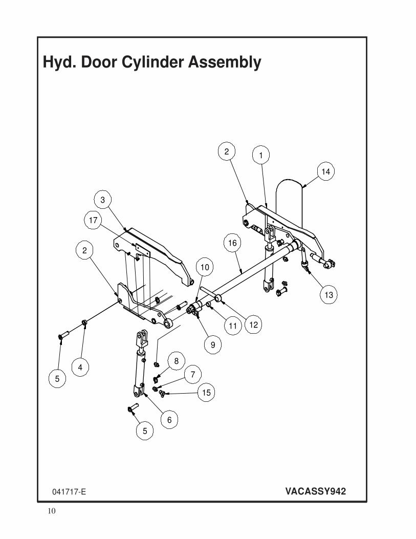
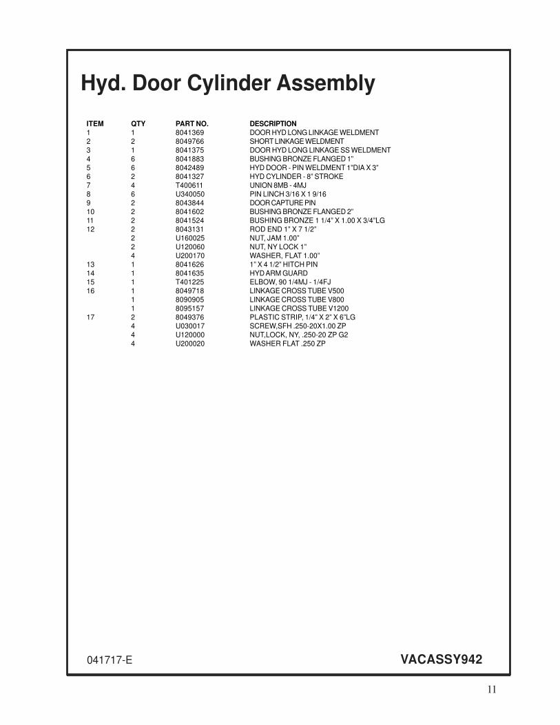
Hyd. Door Cylinder Assembly
041717-E VACASSY942
1211
9
5
8
7
6
3
2
5
4
10
12
15
14
13
16
17
11
041717-E VACASSY942
ITEM QTY PART NO. DESCRIPTION1 1 8041369 DOOR HYD LONG LINKAGE WELDMENT
2 2 8049766 SHORT LINKAGE WELDMENT
3 1 8041375 DOOR HYD LONG LINKAGE SS WELDMENT
4 6 8041883 BUSHING BRONZE FLANGED 1”
5 6 8042489 HYD DOOR - PIN WELDMENT 1”DIA X 3”
6 2 8041327 HYD CYLINDER - 8” STROKE
7 4 T400611 UNION 8MB - 4MJ
8 6 U340050 PIN LINCH 3/16 X 1 9/16
9 2 8043844 DOOR CAPTURE PIN
10 2 8041602 BUSHING BRONZE FLANGED 2”
11 2 8041524 BUSHING BRONZE 1 1/4” X 1.00 X 3/4”LG
12 2 8043131 ROD END 1” X 7 1/2”
2 U160025 NUT, JAM 1.00”
2 U120060 NUT, NY LOCK 1”
4 U200170 WASHER, FLAT 1.00”
13 1 8041626 1” X 4 1/2” HITCH PIN
14 1 8041635 HYD ARM GUARD
15 1 T401225 ELBOW, 90 1/4MJ - 1/4FJ
16 1 8049718 LINKAGE CROSS TUBE V500
1 8090905 LINKAGE CROSS TUBE V800
1 8095157 LINKAGE CROSS TUBE V1200
17 2 8049376 PLASTIC STRIP, 1/4” X 2” X 6”LG
4 U030017 SCREW,SFH .250-20X1.00 ZP
4 U120000 NUT,LOCK, NY, .250-20 ZP G2
4 U200020 WASHER FLAT .250 ZP
Hyd. Door Cylinder Assembly
12
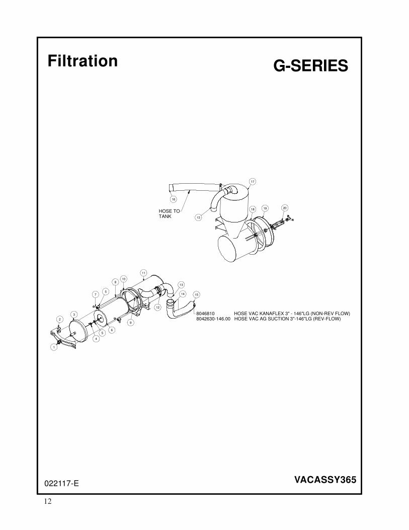
Filtration
VACASSY365022117-E
HOSE TOTANK
1
2
3
4
5
7
6
8
9
11
5
10
16
12
13
14 15
201918
17
13
8046810 HOSE VAC KANAFLEX 3" - 146"LG (NON-REV FLOW)8042630-146.00 HOSE VAC AG SUCTION 3"-146"LG (REV-FLOW)
G-SERIES

13
ITEM QTY PART # DESCRIPTION
1 2 U120060 NUT, LOCK NY 1” - 8
2 1 8044622 DOOR LATCH (AIR FILTER) - WELDMENT
3 1 8044620 575 RF AIR FILTER DOME
4 1 U130080 NUT, WING 1/2 - 13
5 6 U200100 WASHER, FLAT 1/2”
6 1 8031178 FILTER, ELEMENT 575CFM
7 4 8041594 Y-HANDLE
8 4 8041593 EYE BOLT
9 1 8040302 THREADED ROD - 4”LG
10 1 8044819 GASKET, REV FLOW AIR FILTER 575
11 1 8044596 AIR FILTER 575
4 U000420 SCREW, HC 3/8”-16 X 1.00
8 U200600 WASHER, FLAT 3/8”
4 U210061 NUT, HEX NY 3/8”-16
12 1 8030395 3” U-BOLT CLAMP
13 2 8040682 ELBOW, 3” (6”RAD, ID-OD)
14 4 8042605 CLAMP, T-BOLT 3” (350)
15 1 8046810 HOSE VAC KANAFLEX 3-146” (NON-REV FLOW)
* 1 8042630-146.00 HOSE VAC AG SUCTION 3 - 146”LG (REV FLOW)
16 1 8045298 HOSE VAC KANAFLEX 3-64”
17 1 8044589 CYCLONE 575 REV FLOW
4 U000420 SCREW, HC 3/8”-16 X 1.00”
4 U200600 WASHER, FLAT 3/8”
4 U210060 WASHER, FLAT 3/8”
18 1 8041612 GASKET, REV FLOW CYCLONE
19 1 8041402 HD CYCLONE DOME DOOR ASSEMBLY
20 1 8041552 DOOR LATCH (CYCLONE) - WELDMENT
Filtration
022117-E
G-SERIES
VACASSY365
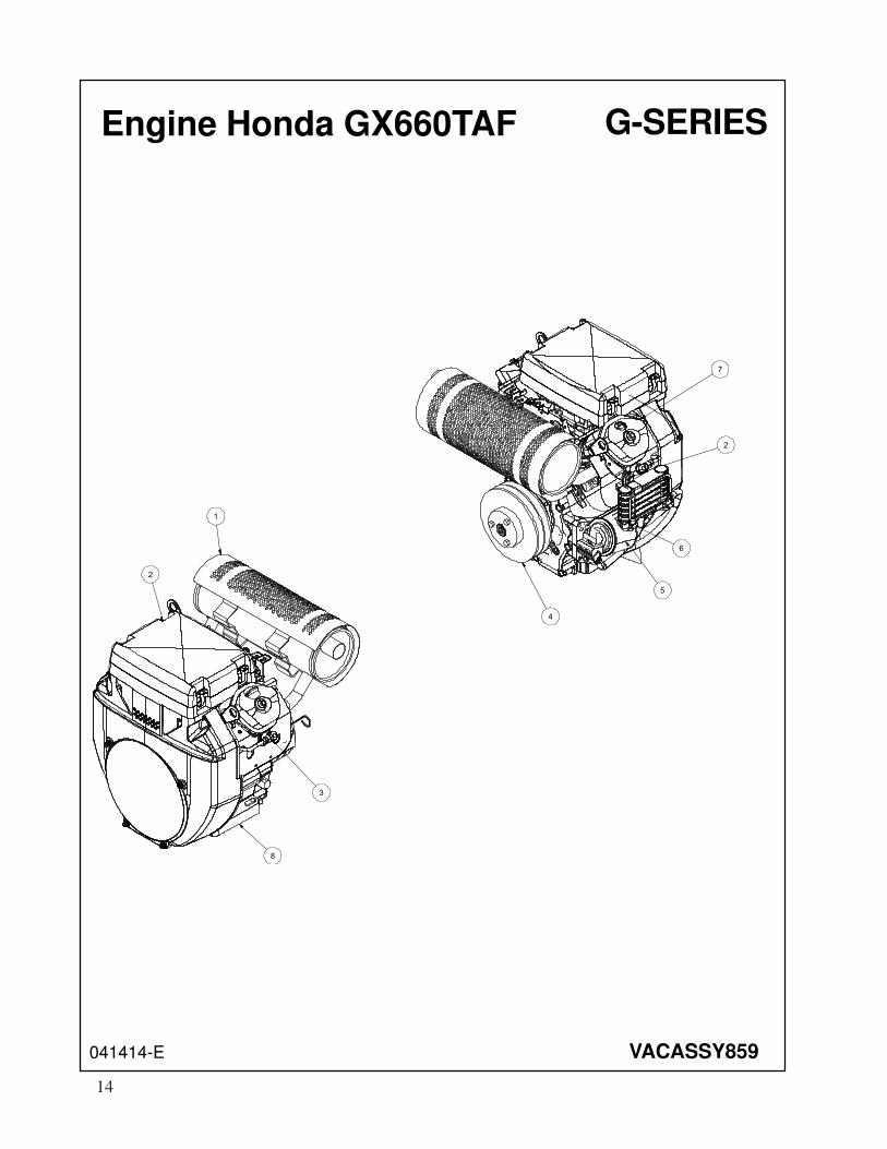
Engine Honda GX660TAF
041414-E VACASSY859
5
2
7
4
6
2
1
3
8
G-SERIES
14

ITEM QTY NUMBER DESCRIPTION
1 1 8046015 MUFFLER, L.H.
2 8046015-1 MUFFLER, EXHAUST GASKET L.H.
2 8046015-2 MUFFLER, EXHAUST NUT L.H.
2 1 8046019 FILTER, AIR ELEMENT
3 2 8046018 SPARK PLUG
4 1 8040697 SHEAVE, 6.55”OD SDS 2-GROOVE
1 8040485 BUSHING, 1 1/8” SDS
5 1 8042719 FILTER, OIL
6 1 8046019 OIL COOLER
7 1 8046014 FUEL FILTER
8 1 8046017 ENGINE, HONDA 24HP GX660
1 8046020 IGNITION KEY
4 U000560 SCREW, HC 3/8-16 X 3.00”
4 U100060 NUT, HEX 3/8”-16
4 U210060 WASHER, LOCK 3/8”
4 U200600 WASHER, FLAT 3/8”
* 1 8030689 MANUAL BOX
* 1 T400041 UNION, 3/8”MJ-M14 MALE W/SEAL
* 1 8043846 HOSE ASSY VAC 6-10 ST-90
* 1 8041517 HOSE VAC FUEL 5/16-36”
* 1 T401067 ELBOW,90 3/8"MP-3/8"M HOSEBARB
* 2 8030436 CLAMP,5/16" FUEL HOSE
* Not Shown
041414-E VACASSY859
Engine Honda GX660TAF G-SERIES
15

Blower Assembly
VACASSY227041414-E
1 2
3
4
5
6
7
8
12
11
13
10
9
14
15
7
161718
7
19
G-SERIES
16
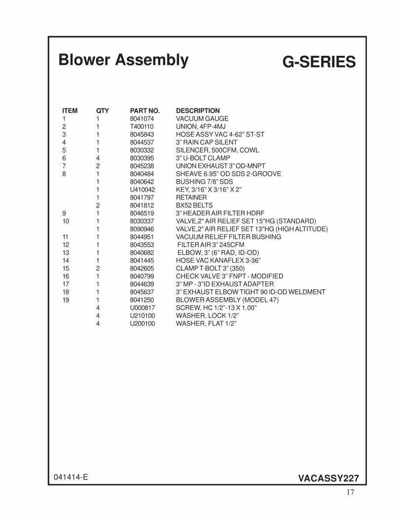
ITEM QTY PART NO. DESCRIPTION
1 1 8041074 VACUUM GAUGE
2 1 T400110 UNION, 4FP-4MJ
3 1 8045843 HOSE ASSY VAC 4-62” ST-ST
4 1 8044537 3” RAIN CAP SILENT
5 1 8030332 SILENCER, 500CFM, COWL
6 4 8030395 3” U-BOLT CLAMP
7 2 8045238 UNION EXHAUST 3” OD-MNPT
8 1 8040484 SHEAVE 6.95” OD SDS 2-GROOVE
1 8040642 BUSHING 7/8” SDS
1 U410042 KEY, 3/16” X 3/16” X 2”
1 8041797 RETAINER
2 8041812 BX52 BELTS
9 1 8046519 3” HEADER AIR FILTER HDRF
10 1 8030337 VALVE,2" AIR RELIEF SET 15"HG (STANDARD)
1 8090946 VALVE,2" AIR RELIEF SET 13"HG (HIGH ALTITUDE)
11 1 8044951 VACUUM RELIEF FILTER BUSHING
12 1 8043553 FILTER AIR 3” 245CFM
13 1 8040682 ELBOW, 3” (6” RAD, ID-OD)14 1 8041445 HOSE VAC KANAFLEX 3-36”
15 2 8042605 CLAMP T-BOLT 3” (350)
16 1 8040799 CHECK VALVE 3” FNPT - MODIFIED
17 1 8044639 3” MP - 3”ID EXHAUST ADAPTER
18 1 8045637 3” EXHAUST ELBOW TIGHT 90 ID-OD WELDMENT
19 1 8041250 BLOWER ASSEMBLY (MODEL 47)
4 U000817 SCREW, HC 1/2”-13 X 1.00”
4 U210100 WASHER, LOCK 1/2”
4 U200100 WASHER, FLAT 1/2”
Blower Assembly
VACASSY227041414-E
G-SERIES
17

Blower Assembly
VACASSY242090815-E
18
17
16
15
13
14
12
11
8
10
9
6 5
2
4
1
3
7
G-SERIES
RF
18

Blower Assembly
090815-E
ITEM QTY NUMBER DESCRIPTION
1 1 8030332 SILENCER, 500CFM, COWL
2 1 8046656 ELBOW, 90 SHARP, 3”OD-ID W/FLANGE
3 1 8046078 REV FLOW HANDLE FACE PLATE
4 1 8046658 ELBOW, 3” 90 4.5”LG X 5.5”LG W/FLANGE
5 1 8041030 3” 4-WAY VALVE W/O FLANGE
6 1 8046504 EXHAUST 3” FLANGE X 3” TUBE WELDMENT
7 1 8046654 ADAPTER 4-WAY VALVE 3” TO BLOWER
8 1 8040484 SHEAVE, 6.95”OD SDS 2-GROOVE
1 8040642 BUSHING 7/8” SDS
1 U410042 KEY, 3/16” X 3/16” X 2”
1 8041797 RETAINER
2 8041812 BX52 BELTS
9 1 8041034 PRESSURE RELIEF VALVE
10 1 8041250 BLOWER ASSEMBLY (MODEL 47)
4 U000817 SCREW, HC 1/2”-13 X 1.00”
4 U210100 WASHER, LOCK 1/2”
4 U200100 WASHER, FLAT 1/2”
11 1 8048413 HOSE VAC AG SUCTION 3-31 1/2”LG
12 1 8046420 HOSE ADAPTER 3” HOSE - 3”MP
13 1 8092928-048.00 HOSE AG HOT AIR 3-48”LG
14 1 8045637 3” EXHAUST ELBOW TIGHT 90 ID-OD
15 1 8046657 3” HEADER AIR FILTER HDRF
16 1 8030337 VALVE,2" AIR RELIEF SET 15"HG (STANDARD)
1 8090946 VALVE,2" AIR RELIEF SET 13"HG (HIGH ALTITUDE)
17 1 8044951 VACUUM RELIEF FILTER BUSHING
18 1 8043553 FILTER, AIR 3” 245CFM
VACASSY242
G-SERIES
RF
19
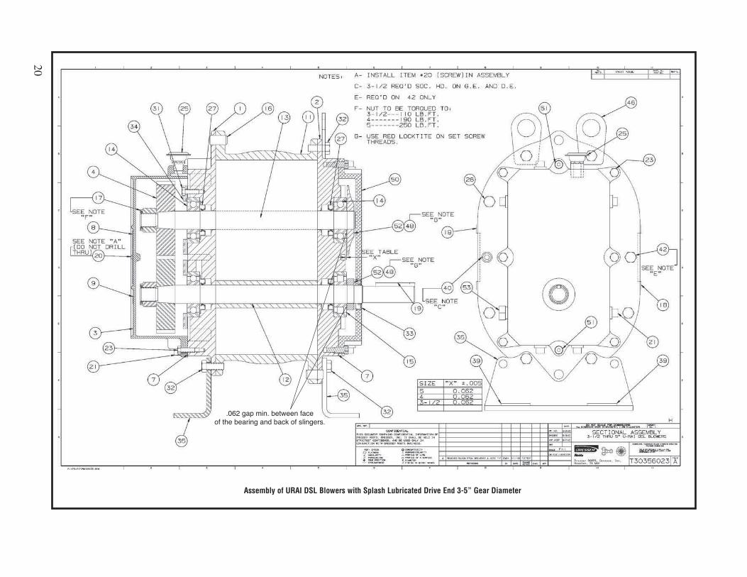
Assembly of URAI DSL Blowers with Splash Lubricated Drive End 3-5” Gear Diameter
20
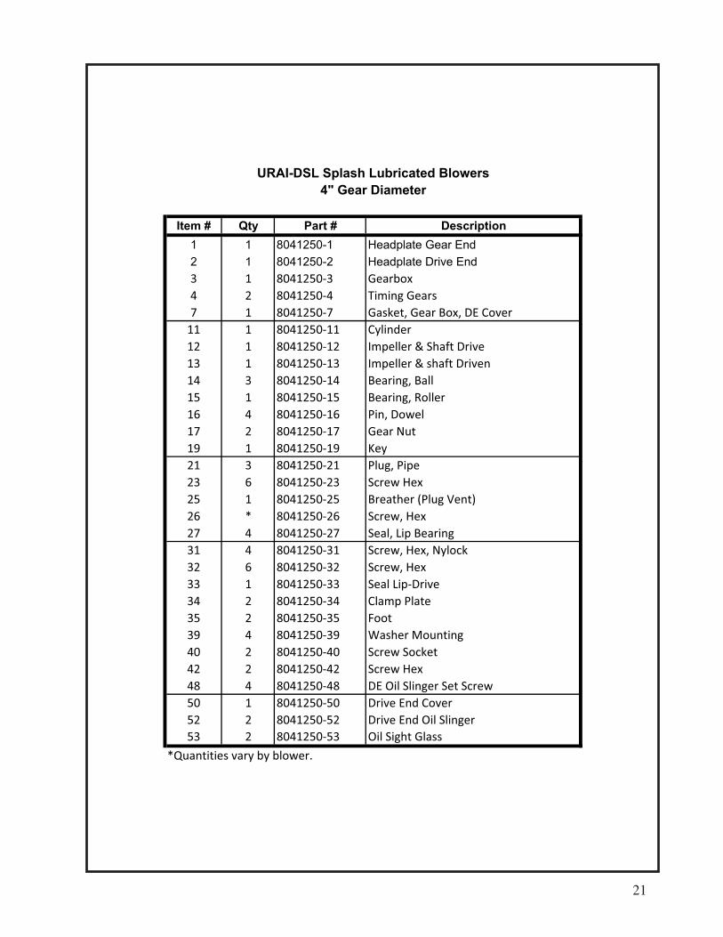
Item # Qty Part # Description
1 1 8041250-1 Headplate Gear End
2 1 8041250-2 Headplate Drive End
3 1 8041250 3 Gearbox
4 2 8041250 4 Timing Gears
7 1 8041250 7 Gasket, Gear Box, DE Cover
11 1 8041250 11 Cylinder
12 1 8041250 12 Impeller & Shaft Drive
13 1 8041250 13 Impeller & shaft Driven
14 3 8041250 14 Bearing, Ball
15 1 8041250 15 Bearing, Roller
16 4 8041250 16 Pin, Dowel
17 2 8041250 17 Gear Nut
19 1 8041250 19 Key
21 3 8041250 21 Plug, Pipe
23 6 8041250 23 Screw Hex
25 1 8041250 25 Breather (Plug Vent)
26 * 8041250 26 Screw, Hex
27 4 8041250 27 Seal, Lip Bearing
31 4 8041250 31 Screw, Hex, Nylock
32 6 8041250 32 Screw, Hex
33 1 8041250 33 Seal Lip Drive
34 2 8041250 34 Clamp Plate
35 2 8041250 35 Foot
39 4 8041250 39 Washer Mounting
40 2 8041250 40 Screw Socket
42 2 8041250 42 Screw Hex
48 4 8041250 48 DE Oil Slinger Set Screw
50 1 8041250 50 Drive End Cover
52 2 8041250 52 Drive End Oil Slinger
53 2 8041250 53 Oil Sight Glass
*Quantities vary by blower.
URAI-DSL Splash Lubricated Blowers
4" Gear Diameter
21
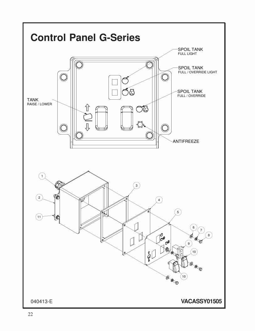
Control Panel G-Series
VACASSY01505040413-E
SPOIL TANKFULL LIGHT
SPOIL TANKFULL / OVERRIDE LIGHT
TANKRAISE / LOWER
ANTIFREEZE
SPOIL TANKFULL / OVERRIDE
1
2
3
4
5
8
76
9
10
10
11
22

ITEM QTY PART NO. DESCRIPTION
1 1 X000109 STRAIN RELIEF, 3/4”
2 1 8048638 LEG CONTROL BOX (SMALL)
3 1 8048634 COVER PLATE GASKET
4 1 8048633 COVER PLATE
5 1 J200637 DECAL, CONTROL PANEL
6 8 U200020 WASHER, FLAT 1/4”
7 8 U210020 WASHER, LOCK 1/4”
8 8 U000040 SCREW, HC 1/4”-20 X .75”
9 1 X000260 LIGHT, LED DUAL PANEL
10 2 X000274 SWITCH, ROCKER DPST (ON) OFF (ON)
* NOT SHOWN
040413-E VACASSY01505
Control Panel G-Series
23
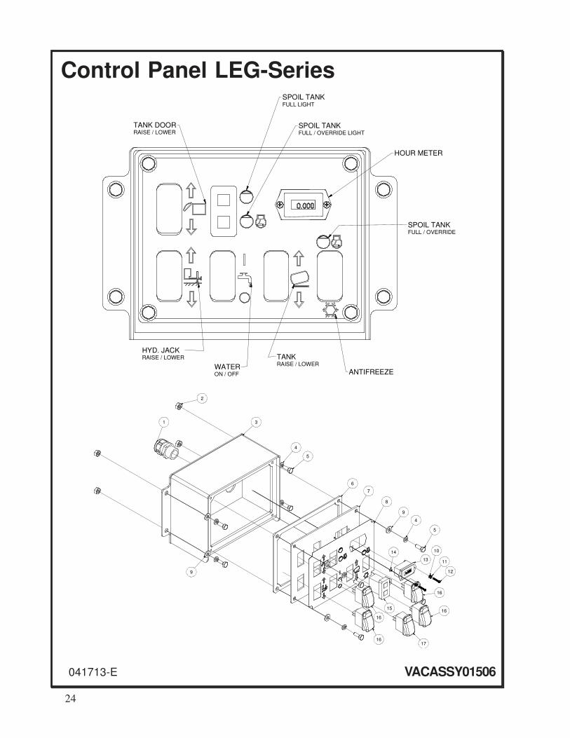
Control Panel LEG-Series
VACASSY01506041713-E
2
1 3
4
5
9
6
7
8
9
4
5
12
11
10
13
14
1615
1716
16
16
SPOIL TANK
FULL LIGHT
SPOIL TANKFULL / OVERRIDE LIGHT
ANTIFREEZE
SPOIL TANKFULL / OVERRIDE
TANKRAISE / LOWER
TANK DOORRAISE / LOWER
HYD. JACKRAISE / LOWER
WATERON / OFF
HOUR METER
24

ITEM QTY PART NO. DESCRIPTION
1 1 X000109 STRAIN RELIEF, 3/4”
2 4 U120100 NUT, LOCK 1/4”-20
3 1 8048631 LEG CONTROL BOX (LARGE)
4 8 U210020 WASHER, LOCK 1/4”
5 8 U000040 SCREW, HC 1/4”-20 X .750
6 1 8048627 COVER PLATE GASKET
7 1 8048626 COVER PLATE
8 1 J200635 DECAL, CONTROL PANEL LEG
9 8 U200020 WASHER, FLAT 1/4”
10 2 U210008 WASHER, LOCK #4 ZP INTERNAL
11 2 U210009 WASHER, LOCK #4 EXTERNAL TOOTH
12 2 U030502 SCREW, PAN HD PHIL #4-40 X .750
13 1 X000350 HOUR METER
14 2 U100004 NUT, HEX M/S #4-40
15 1 X000260 LIGHT, LED DUAL PANEL
16 4 X000274 SWITCH, ROCKER DPST (ON) OFF (ON)
17 1 X000270 SWITCH, ROCKER SPST ON - OFF
* NOT SHOWN
041713-E VACASSY01506
Control Panel LEG-Series
25

Schematic
OPTIONALP.C. ORIFICE(CAVITY STD.)(SPECIFY FLOW)
P T
C1C2 #6 SAE PORTS
16
15
14
32
36
352928
27
38
23
37
31
33
34
26
2
10
3
4
5
1
48
12
13
116
21
25
45
46
47
24
4244
43
19
2018
17
8
7
9
22
39
4041
30
30
12
34
5
7
6
8
9
18
20
21
10
1219
14
16
1511
27
26
25
13
17
17
24
23
22
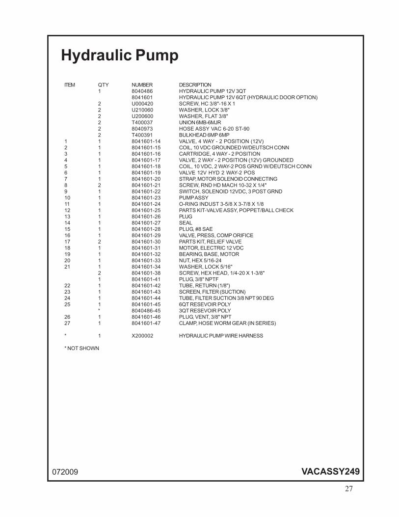
Hydraulic Pump
072009 VACASSY249
26
Hydraulic Pump
072009 VACASSY249
ITEM QTY NUMBER DESCRIPTION
1 8040486 HYDRAULIC PUMP 12V 3QT
8041601 HYDRAULIC PUMP 12V 6QT (HYDRAULIC DOOR OPTION)
2 U000420 SCREW, HC 3/8"-16 X 1
2 U210060 WASHER, LOCK 3/8"
2 U200600 WASHER, FLAT 3/8"
2 T400037 UNION 6MB-6MJR
2 8040973 HOSE ASSY VAC 6-20 ST-90
2 T400391 BULKHEAD 6MP 6MP
1 1 8041601-14 VALVE, 4 WAY - 2 POSITION (12V)
2 1 8041601-15 COIL, 10 VDC GROUNDED W/DEUTSCH CONN
3 1 8041601-16 CARTRIDGE, 4 WAY - 2 POSITION
4 1 8041601-17 VALVE, 2 WAY - 2 POSITION (12V) GROUNDED
5 1 8041601-18 COIL, 10 VDC, 2 WAY-2 POS GRND W/DEUTSCH CONN
6 1 8041601-19 VALVE 12V HYD 2 WAY-2 POS
7 1 8041601-20 STRAP, MOTOR SOLENOID CONNECTING
8 2 8041601-21 SCREW, RND HD MACH 10-32 X 1/4"
9 1 8041601-22 SWITCH, SOLENOID 12VDC, 3 POST GRND
10 1 8041601-23 PUMP ASSY
11 1 8041601-24 O-RING INDUST 3-5/8 X 3-7/8 X 1/8
12 1 8041601-25 PARTS KIT-VALVE ASSY, POPPET/BALL CHECK
13 1 8041601-26 PLUG
14 1 8041601-27 SEAL
15 1 8041601-28 PLUG, #8 SAE
16 1 8041601-29 VALVE, PRESS, COMP ORIFICE
17 2 8041601-30 PARTS KIT, RELIEF VALVE
18 1 8041601-31 MOTOR, ELECTRIC 12 VDC
19 1 8041601-32 BEARING, BASE, MOTOR
20 1 8041601-33 NUT, HEX 5/16-24
21 1 8041601-34 WASHER, LOCK 5/16"
2 8041601-38 SCREW, HEX HEAD, 1/4-20 X 1-3/8"
1 8041601-41 PLUG, 3/8" NPTF
22 1 8041601-42 TUBE, RETURN (1/8")
23 1 8041601-43 SCREEN, FILTER (SUCTION)
24 1 8041601-44 TUBE, FILTER SUCTION 3/8 NPT 90 DEG
25 1 8041601-45 6QT RESEVOIR POLY
* 8040486-45 3QT RESEVOIR POLY
26 1 8041601-46 PLUG, VENT, 3/8" NPT
27 1 8041601-47 CLAMP, HOSE WORM GEAR (IN SERIES)
* 1 X200002 HYDRAULIC PUMP WIRE HARNESS
* NOT SHOWN
27
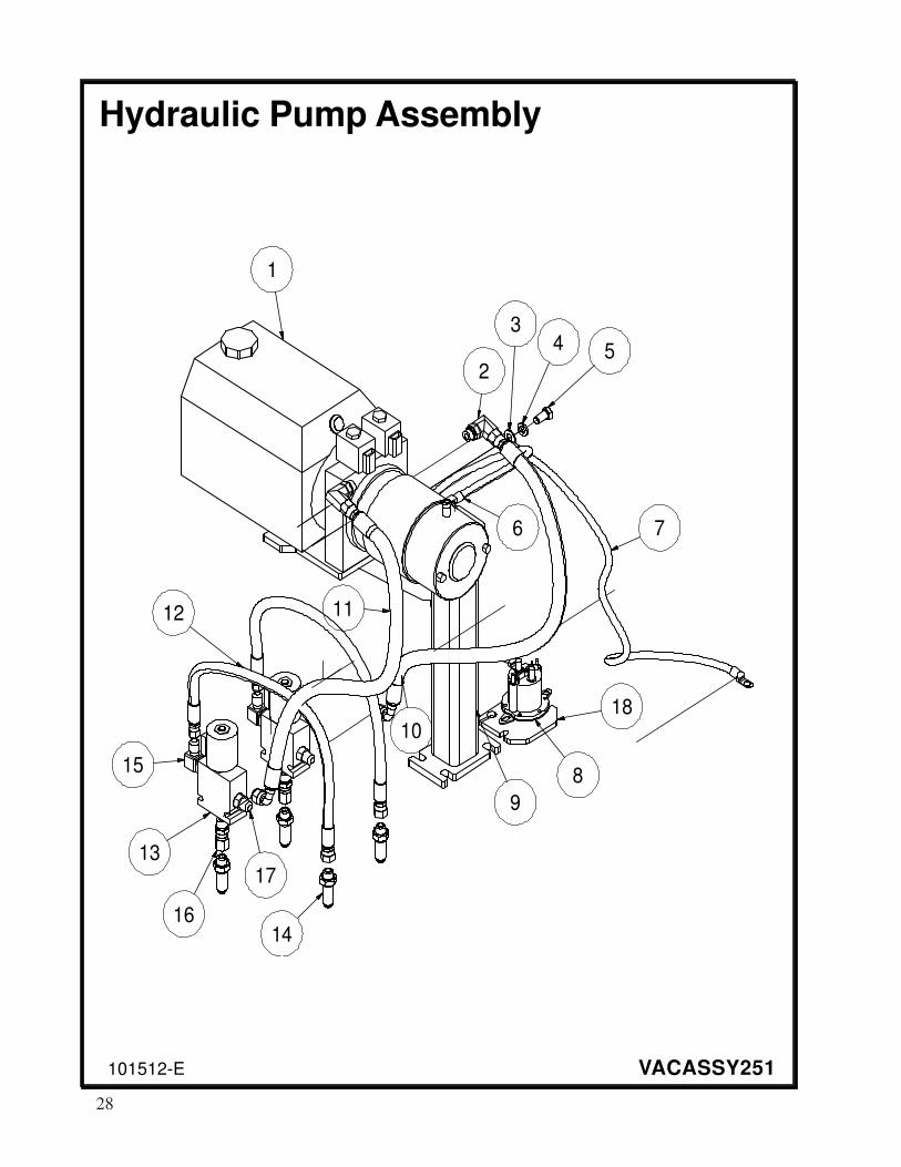
Hydraulic Pump Assembly
101512-E VACASSY251
1
2
10
1112
13
14
9
8
76
54
3
15
17
16
18
28

ITEM QTY PART DESCRIPTION
1 1 8046300 PUMP, HYD 12V 4.5QT
2 2 T401250 ELBOW, 90 3/8” MB-MJ
3 1 U200600 WASHER, FLAT 3/8”
4 1 U210060 WASHER, LOCK 3/8”
5 1 U200400 SCREW, HC 3/8”-16 X .750
6 1 X300233 CABLE, BATTERY HOT 1GA 26”
2 X300251 LUG, CABLE 1GA 3/8” HOLE
7 1 X300224 CABLE, BATTERY GROUND 1GA 21”
2 X300251 LUG, CABLE 1GA 3/8” HOLE
8 1 8046258 SWITCH HYD PUMP 12V RELOCATE
2 U000040 SCREW, HC 1/4”-20 X .75 ZP G5
2 U200020 WASHER, FLAT 1/4” ZP
2 U210020 WASHER, LOCK 1/4” ZP
2 U100020 NUT, HEX 1/4”-20
9 1 8043499 BRACKET 36/49 12V HYD PUMP
1 8047283 BRACKET 99AW HYD PUMP
* 2 U000460 SCREW, HC 3/8”-16 X 1.50 ZP G5
* 2 U000480 SCREW, HC 3/8”-16 X 1.75 ZP G5
* 5 U200060 WASHER, FLAT 3/8”
* 5 U210060 WASHER, LOCK 3/8”
* 4 U100060 NUT, HEX 3/8”-16
* 1 U000441 SCREW, HC 3/8”-16 X 1.25 ZP G8
10 1 8046685 HOSE ASSY VAC 6-25” ST-90 (500LE/LEHD)
1 8046686 HOSE ASSY VAC 6-22” ST-90 (800LE/LEHD)
1 8040973 HOSE ASSY VAC 6-20” ST-90 (73/99)
11 1 8046687 HOSE ASSY VAC 6-23” ST-90 (500LE/LEHD)
1 8040973 HOSE ASSY VAC 6-20” ST-90 (800LE/LEHD)
1 8040973 HOSE ASSY VAC 6-20” ST-90 (73/99)
12 2 8040971 HOSE ASSY VAC 4-19” ST-ST6FJ (LE/LEHD)
13 2 8041788 VALVE, SOLENOID 3-WAY W/ INT C4K
14 4 T400391 BULKHEAD 3/8”MJ - 3/8”MJ
15 2 T401250 ELBOW, 90 3/8”MB - 3/8”MJ
16 2 T400036 UNION, 3/8”MB - 3/8”FJ
17 2 T400037 UNION, 3/8”MB - 3/8”MJ
18 1 8046127 BRACKET PUMP SOLENOID
* NOT SHOWN
101512-E VACASSY251
Hydraulic Pump Assembly
29
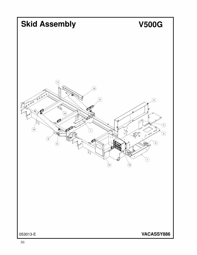
Skid Assembly V500G
053013-E VACASSY886
1
2
3
4
5
1514
6
7
12
8
9
13
11
10
30
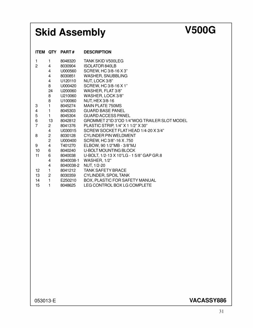
Skid Assembly V500G
053013-E VACASSY886
ITEM QTY PART # DESCRIPTION
1 1 8048320 TANK SKID V500LEG
2 4 8030904 ISOLATOR 840LB
4 U000560 SCREW, HC 3/8-16 X 3”
4 8030851 WASHER, SNUBBLING
4 U120110 NUT, LOCK 3/8”
8 U000420 SCREW, HC 3/8-16 X 1”
24 U200060 WASHER, FLAT 3/8”
8 U210060 WASHER, LOCK 3/8”
8 U100060 NUT, HEX 3/8-16
3 1 8045274 MAIN PLATE 750MS
4 1 8045303 GUARD BASE PANEL
5 1 8045304 GUARD ACCESS PANEL
6 13 8042812 GROMMET 2”ID 3”OD 1/4”WOG TRAILER SLOT MODEL
7 2 8041376 PLASTIC STRIP, 1/4” X 1 1/2” X 30”
4 U030015 SCREW SOCKET FLAT HEAD 1/4-20 X 3/4”
8 2 8030128 CYLINDER PIN WELDMENT
2 U000400 SCREW, HC 3/8”-16 X .750
9 4 T401270 ELBOW, 90 1/2”MB - 3/8”MJ
10 6 8040240 U-BOLT MOUNTING BLOCK
11 6 8040038 U-BOLT, 1/2-13 X 10”LG - 1 5/8” GAP GR.8
4 8040038-1 WASHER, 1/2”
4 8040038-2 NUT, 1/2-20
12 1 8041212 TANK SAFETY BRACE
13 2 8030359 CYLINDER, SPOIL TANK
14 1 E250210 BOX, PLASTIC FOR SAFETY MANUAL
15 1 8048625 LEG CONTROL BOX LG COMPLETE
31
Skid Assembly V800G
053013-E VACASSY870
1
2
3
4
5
1514
6
7
12
8
9
13
11
10
32

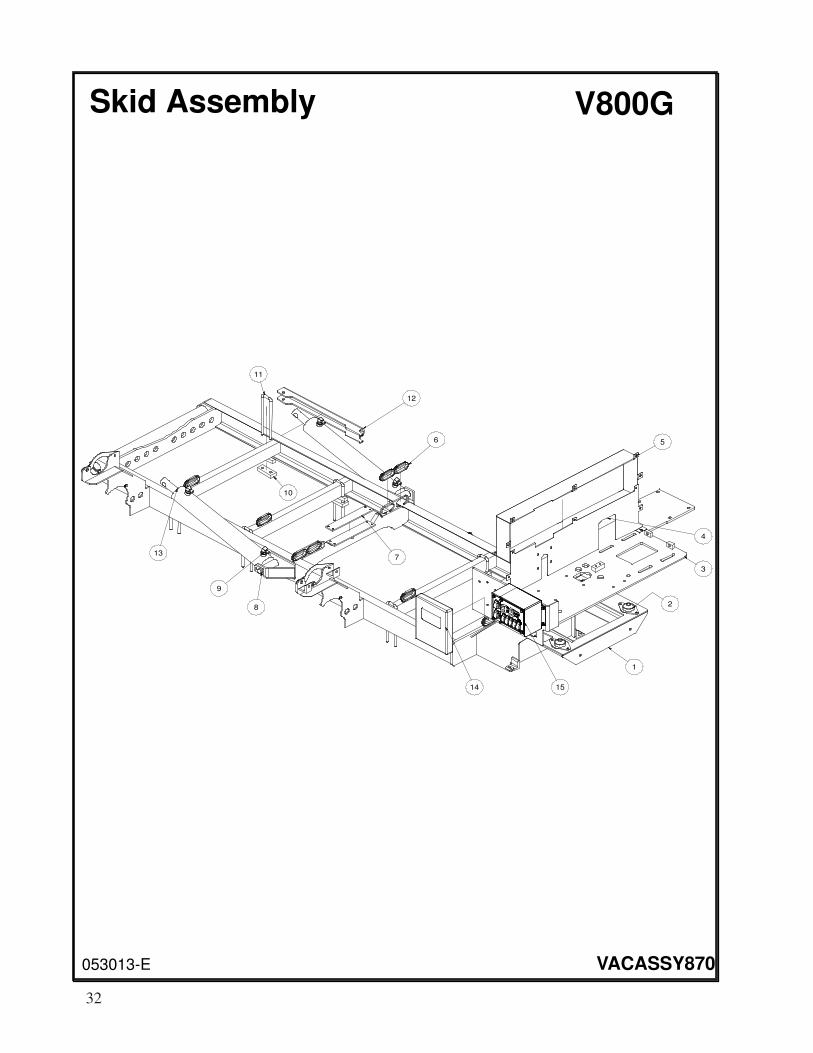
Skid Assembly V800G
053013-E VACASSY870
ITEM QTY PART # DESCRIPTION
1 1 8046462 TANK SKID V750MS
2 4 8030904 ISOLATOR 840LB
4 U000560 SCREW, HC 3/8-16 X 3”
4 8030851 WASHER, SNUBBLING
4 U120110 NUT, LOCK 3/8”
8 U000420 SCREW, HC 3/8-16 X 1”
24 U200060 WASHER, FLAT 3/8”
8 U210060 WASHER, LOCK 3/8”
8 U100060 NUT, HEX 3/8-16
3 1 8045274 MAIN PLATE 750MS
4 1 8045303 GUARD BASE PANEL
5 1 8045304 GUARD ACCESS PANEL
6 13 8042812 GROMMET 2”ID 3”OD 1/4”WOG TRAILER SLOT MODEL
7 2 8041376 PLASTIC STRIP, 1/4” X 1 1/2” X 30”
4 U030015 SCREW SOCKET FLAT HEAD 1/4-20 X 3/4”
8 2 8030128 CYLINDER PIN WELDMENT
2 U000400 SCREW, HC 3/8”-16 X .750
9 4 T401270 ELBOW, 90 1/2”MB - 3/8”MJ
10 6 8040240 U-BOLT MOUNTING BLOCK
11 6 8040038 U-BOLT, 1/2-13 X 10”LG - 1 5/8” GAP GR.8
4 8040038-1 WASHER, 1/2”
4 8040038-2 NUT, 1/2-20
12 1 8041212 TANK SAFETY BRACE
13 2 8030359 CYLINDER, SPOIL TANK
14 1 E250210 BOX, PLASTIC FOR SAFETY MANUAL
15 1 8048625 LEG CONTROL BOX LG COMPLETE
33
Skid Assembly V1200G
050813-E VACASSY01104
1
2
3
4
5
6
7
11
12
8
9
10
34
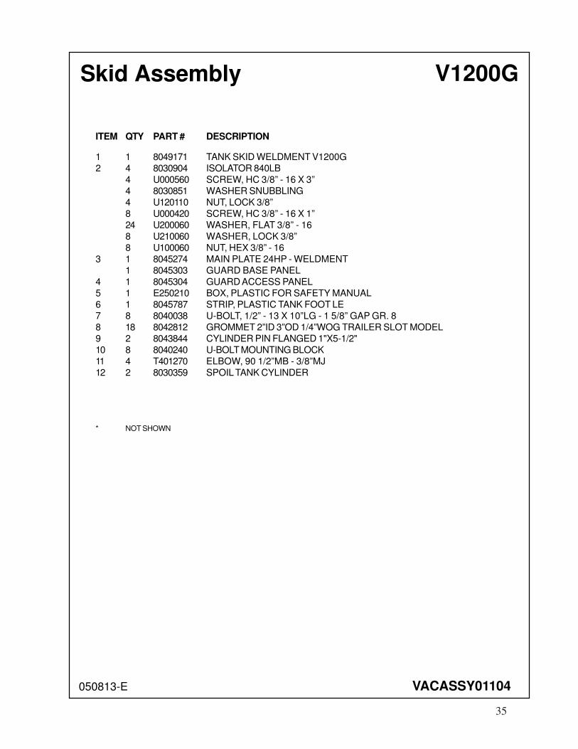
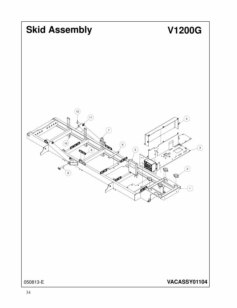
Skid Assembly V1200G
050813-E VACASSY01104
ITEM QTY PART # DESCRIPTION
1 1 8049171 TANK SKID WELDMENT V1200G
2 4 8030904 ISOLATOR 840LB
4 U000560 SCREW, HC 3/8” - 16 X 3”
4 8030851 WASHER SNUBBLING
4 U120110 NUT, LOCK 3/8”
8 U000420 SCREW, HC 3/8” - 16 X 1”
24 U200060 WASHER, FLAT 3/8” - 16
8 U210060 WASHER, LOCK 3/8”
8 U100060 NUT, HEX 3/8” - 16
3 1 8045274 MAIN PLATE 24HP - WELDMENT
1 8045303 GUARD BASE PANEL
4 1 8045304 GUARD ACCESS PANEL
5 1 E250210 BOX, PLASTIC FOR SAFETY MANUAL
6 1 8045787 STRIP, PLASTIC TANK FOOT LE
7 8 8040038 U-BOLT, 1/2” - 13 X 10”LG - 1 5/8” GAP GR. 8
8 18 8042812 GROMMET 2”ID 3”OD 1/4”WOG TRAILER SLOT MODEL
9 2 8043844 CYLINDER PIN FLANGED 1"X5-1/2"
10 8 8040240 U-BOLT MOUNTING BLOCK
11 4 T401270 ELBOW, 90 1/2”MB - 3/8”MJ
12 2 8030359 SPOIL TANK CYLINDER
* NOT SHOWN
35
36
080216-E
Trailer Assy 712
VACASSY908
1
1
3
4
4
5
6
7
8
8
7
9 10
7
37
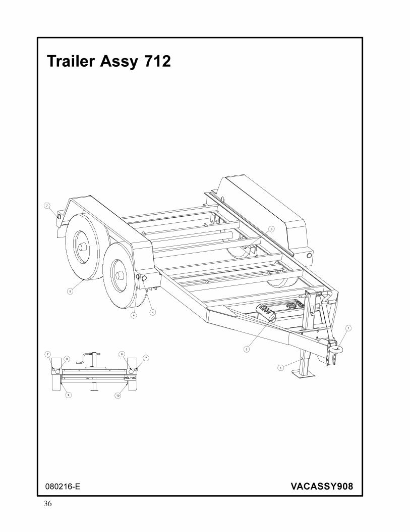
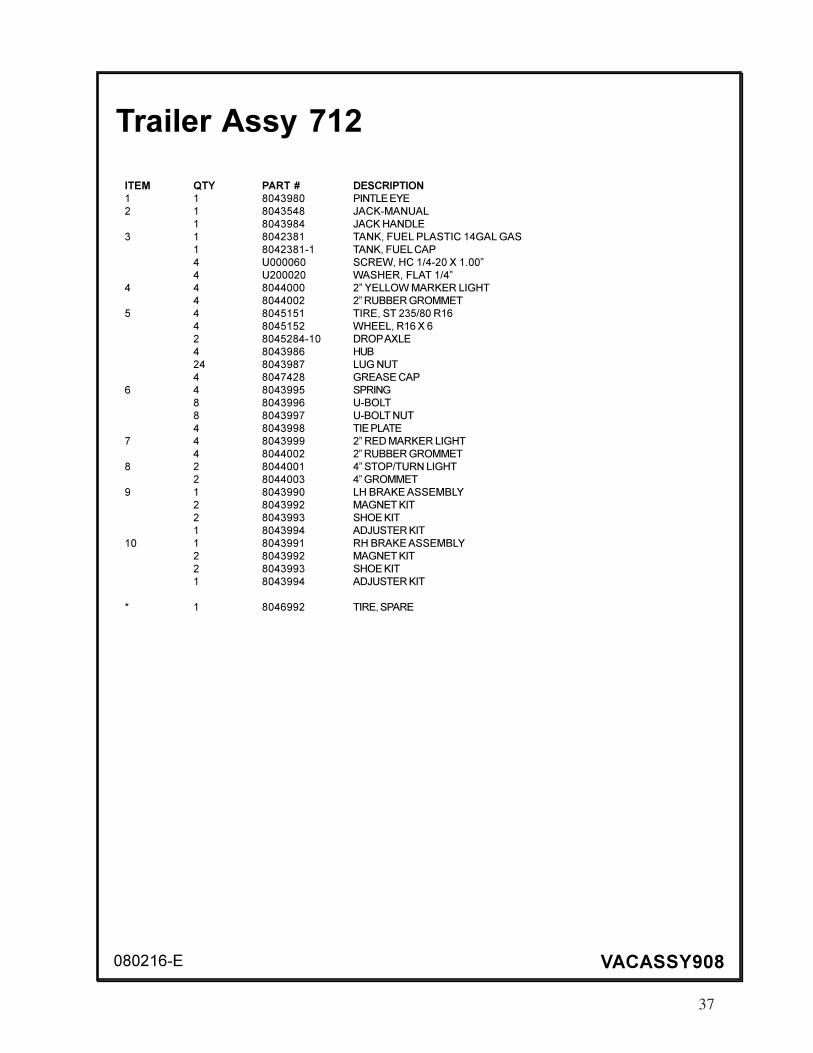
080216-E VACASSY908
Trailer Assy 712
ITEM QTY PART # DESCRIPTION
1 1 8043980 PINTLE EYE
2 1 8043548 JACK-MANUAL
1 8043984 JACK HANDLE
3 1 8042381 TANK, FUEL PLASTIC 14GAL GAS
1 8042381-1 TANK, FUEL CAP
4 U000060 SCREW, HC 1/4-20 X 1.00”
4 U200020 WASHER, FLAT 1/4”
4 4 8044000 2” YELLOW MARKER LIGHT
4 8044002 2” RUBBER GROMMET
5 4 8045151 TIRE, ST 235/80 R16
4 8045152 WHEEL, R16 X 6
2 8045284-10 DROP AXLE
4 8043986 HUB
24 8043987 LUG NUT
4 8047428 GREASE CAP
6 4 8043995 SPRING
8 8043996 U-BOLT
8 8043997 U-BOLT NUT
4 8043998 TIE PLATE
7 4 8043999 2” RED MARKER LIGHT
4 8044002 2” RUBBER GROMMET
8 2 8044001 4” STOP/TURN LIGHT
2 8044003 4” GROMMET
9 1 8043990 LH BRAKE ASSEMBLY
2 8043992 MAGNET KIT
2 8043993 SHOE KIT
1 8043994 ADJUSTER KIT
10 1 8043991 RH BRAKE ASSEMBLY
2 8043992 MAGNET KIT
2 8043993 SHOE KIT
1 8043994 ADJUSTER KIT
* 1 8046992 TIRE, SPARE
38
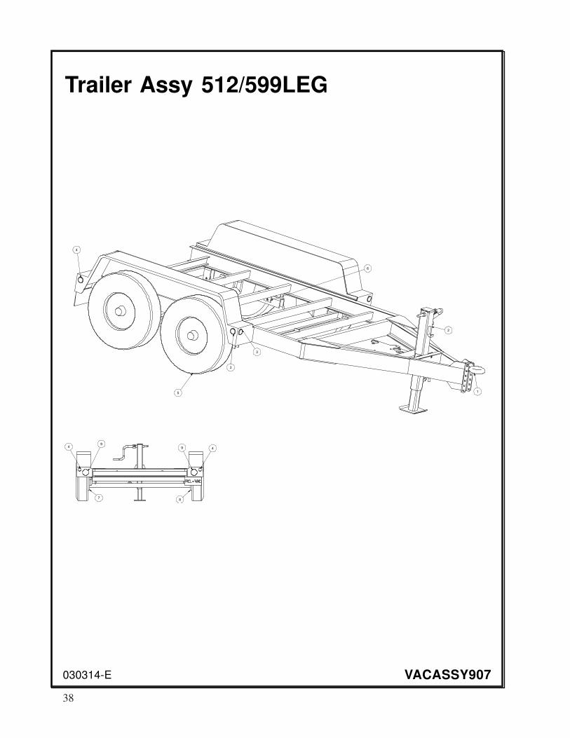
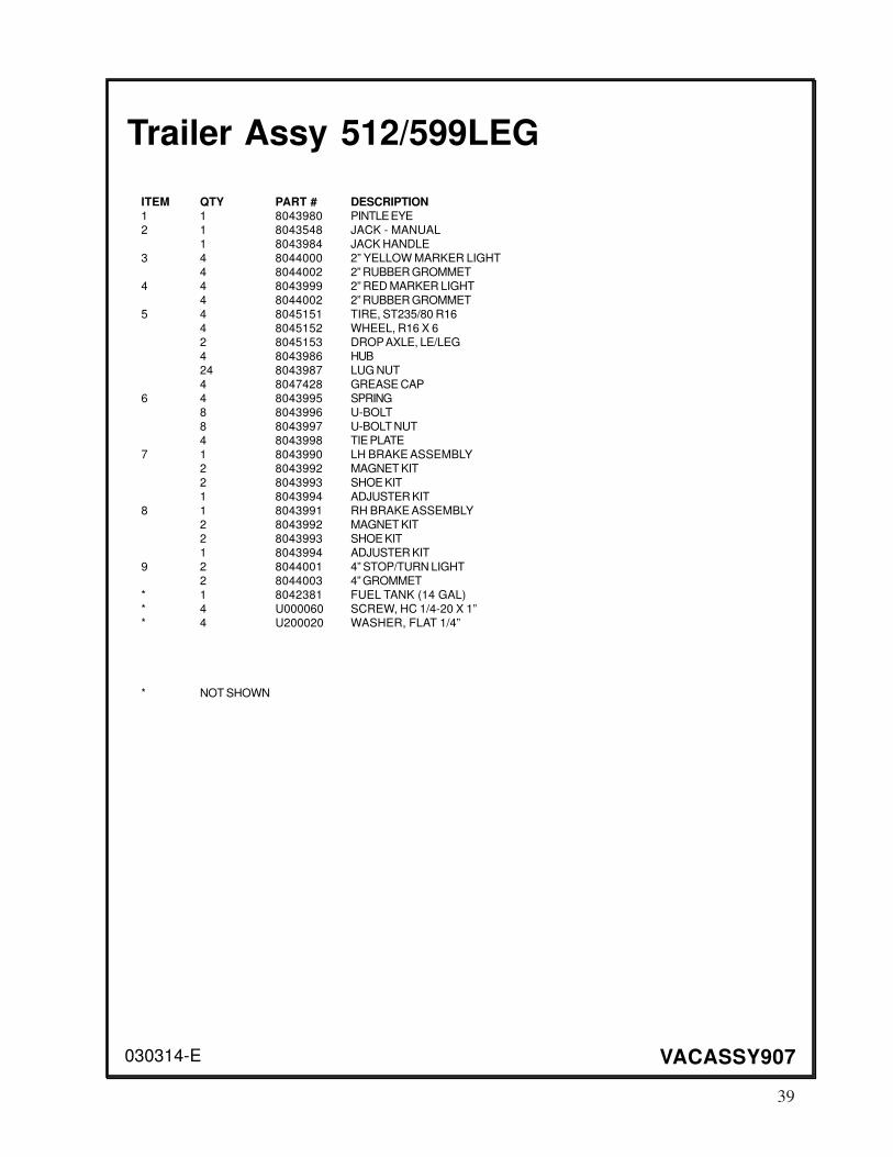
030314-E
Trailer Assy 512/599LEG
VACASSY907
1
2
3
3
5
6
4
49
94
78
39
030314-E VACASSY907
Trailer Assy 512/599LEG
ITEM QTY PART # DESCRIPTION1 1 8043980 PINTLE EYE
2 1 8043548 JACK - MANUAL
1 8043984 JACK HANDLE
3 4 8044000 2” YELLOW MARKER LIGHT
4 8044002 2” RUBBER GROMMET
4 4 8043999 2” RED MARKER LIGHT
4 8044002 2” RUBBER GROMMET
5 4 8045151 TIRE, ST235/80 R16
4 8045152 WHEEL, R16 X 6
2 8045153 DROP AXLE, LE/LEG
4 8043986 HUB
24 8043987 LUG NUT
4 8047428 GREASE CAP
6 4 8043995 SPRING
8 8043996 U-BOLT
8 8043997 U-BOLT NUT
4 8043998 TIE PLATE
7 1 8043990 LH BRAKE ASSEMBLY
2 8043992 MAGNET KIT
2 8043993 SHOE KIT
1 8043994 ADJUSTER KIT
8 1 8043991 RH BRAKE ASSEMBLY
2 8043992 MAGNET KIT
2 8043993 SHOE KIT
1 8043994 ADJUSTER KIT
9 2 8044001 4” STOP/TURN LIGHT
2 8044003 4” GROMMET
* 1 8042381 FUEL TANK (14 GAL)
* 4 U000060 SCREW, HC 1/4-20 X 1”
* 4 U200020 WASHER, FLAT 1/4”
* NOT SHOWN
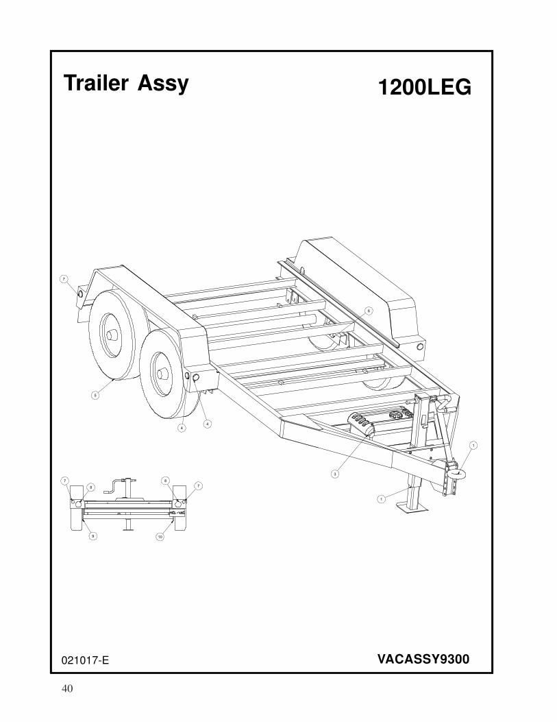
40
021017-E
Trailer Assy
VACASSY9300
1
1
3
4
4
5
6
7
8
8
7
9 10
7
1200LEG

41
021017-E VACASSY9300
Trailer Assy
ITEM QTY PART # DESCRIPTION1 8047881 TRAILER, 1200LEG
1 1 8043980 PINTLE EYE
2 1 8043548 JACK-MANUAL
1 8043984 JACK HANDLE
3 1 8042381 TANK, FUEL PLASTIC 14GAL GAS
1 8042381-1 TANK, FUEL CAP
4 U000060 SCREW, HC 1/4-20 X 1.00”
4 U200020 WASHER, FLAT 1/4”
4 4 8044000 2” YELLOW MARKER LIGHT
4 8044002 2” RUBBER GROMMET
5 4 8046294 TIRE, ST 215 / 75 R 17.5
4 8046295 WHEEL, R17.5 X 6.75
2 8047881-10 DROP AXLE
4 8046297 HUB
24 8046298 LUG NUT
4 8047429 GREASE CAP
6 4 8046299 SPRING
8 8046301 U-BOLT
8 8046302 U-BOLT NUT
4 8046303 TIE PLATE
7 4 8043999 2” RED MARKER LIGHT
4 8044002 2” RUBBER GROMMET
8 2 8044001 4” STOP/TURN LIGHT
2 8044003 4” GROMMET
9 1 8046307 LH BRAKE ASSEMBLY
2 8046304 MAGNET KIT
2 8046305 SHOE KIT
1 8046306 ADJUSTER KIT
10 1 8046308 RH BRAKE ASSEMBLY
2 8046304 MAGNET KIT
2 8046305 SHOE KIT
1 8046306 ADJUSTER KIT
* 1 8046994 TIRE, SPARE
1200LEG
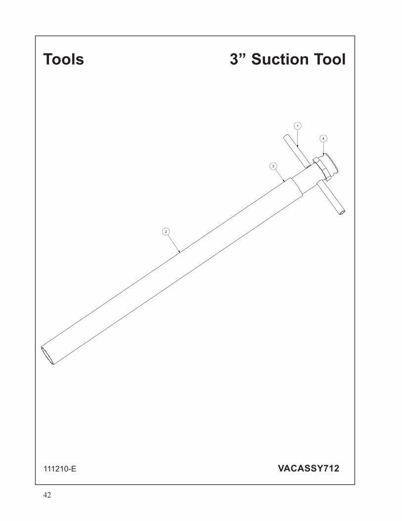
Tools 3” Suction Tool
111210-E VACASSY712
4
1
2
3
42
Tools
111210-E VACASSY712
3” Suction Tool
ITEM QTY NUMBER DESCRIPTION
1 8030215 TOOL VAC SUCTION 3" COMPLETE
1 1 8030317 TOOL VAC HANDLE ASSEMBLY 3"
2 1 8030313 PVC VACUUM TUBE 3"
3 1 8030356 CLAMP,4"PUNCHLOCK P16-S
4 1 8030391 COUPLING, 3" BANJO
43

44
HOSES
030314-E VACASSY938
1
2
3”
45
030314-E VACASSY938
HOSES
ITEM QTY PART NO. DESCRIPTION
1 1 8041102 6”PVC STORAGE TUBE 10’LG
1 8030925 END CAP 6”
1 8041485 LANYARD CABLE
1 8043198 HOSE STORAGE CLAMP
2 U200060 WASHER. FLAT 3/8”
2 U100060 NUT, HEX 3/8”
1 8041101 HOSE STORAGE RETAINING ROD
1 R700170 R-CLIP, 1/2 - 5/8 SHANK
2 1 8040338 HOSE VAC KANAFLEX 3-110”
1 8046441 CAMLOCK, 3” AL FCAM X MBARB
1 8046440 CAMCOCK, 3” AL MCAM X MBARB
2 8030356 CLAMP, 4.5” PUNCHLOCK P18-S
3”

PAGE LEFT BLANK
46

47

PAGE LEFT BLANK
48
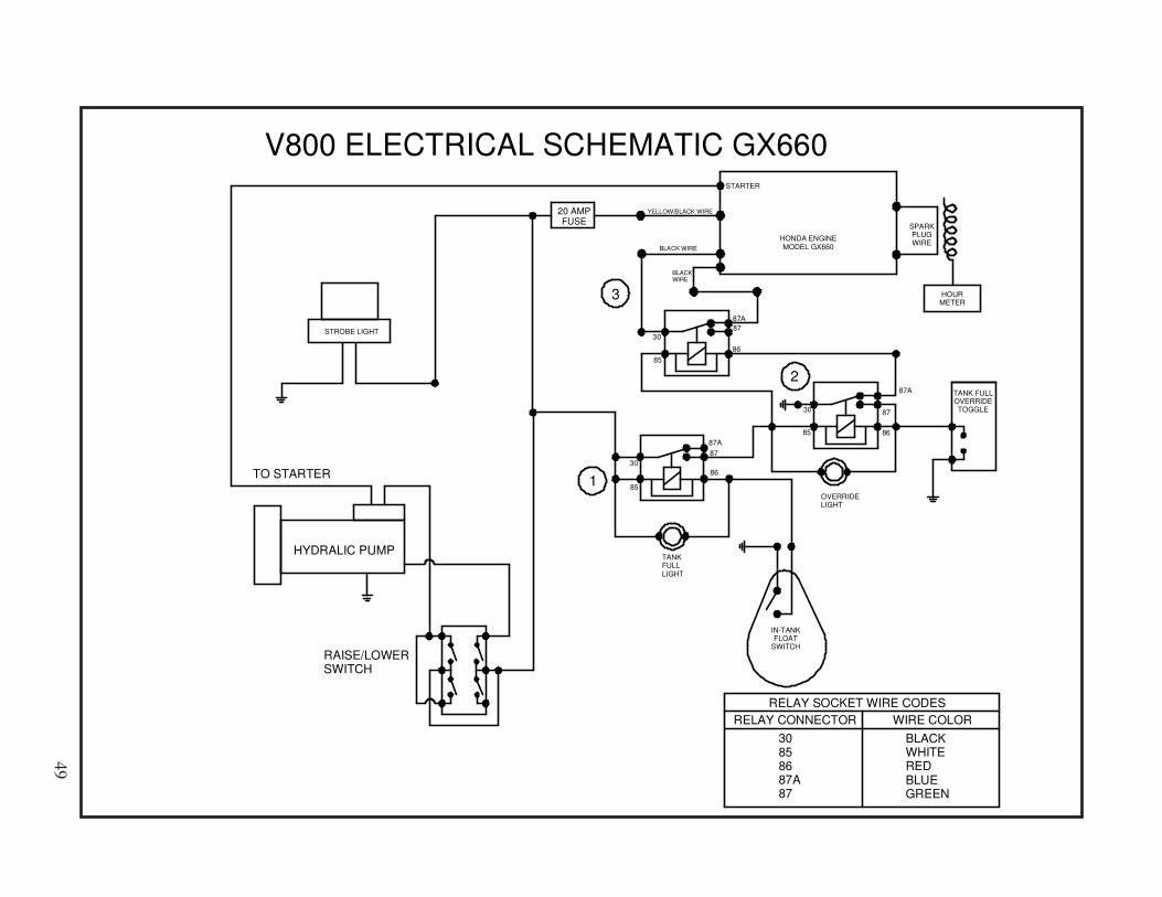
TANK FULL
OVERRIDE
TOGGLE
IN-TANK
FLOAT
SWITCH
HONDA ENGINE
MODEL GX660BLACK WIRE
20 AMP
FUSE
YELLOW/BLACK WIRE
HOUR
METER
SPARK
PLUG
WIRE
TANK
FULL
LIGHT
OVERRIDE
LIGHT
87A
87
8685
30
30
30
85
85
87A
87A
87
87
86
86
3
2
1
STARTER
BLACK
WIRE
WIRE COLOR
30
85
86
87A
87
RELAY CONNECTOR
RELAY SOCKET WIRE CODES
BLACK
WHITE
RED
BLUE
GREEN
STROBE LIGHT
RAISE/LOWER
SWITCH
HYDRALIC PUMP
TO STARTER
V800 ELECTRICAL SCHEMATIC GX660
49

PAGE LEFT BLANK
50
INSTALLATION OPERATION MAINTENANCE
US $3.00, Canada $4.50
Universal RAI® and URAI DSL Blowers
❏ Read starting check points under OPERATION. Runequipment briefly to check for installation errors andmake corrections. Follow with a trial run under normaloperating conditions.
❏ In event of trouble during installation or operation, donot attempt repairs of Roots furnished equipment. NotifyRoots, giving all nameplate information plus an outlineof operating conditions and a description of the trouble.Unauthorized attempts at equipment repair may voidRoots warranty.
❏ Units out of warranty may be repaired or adjusted by theowner. Good inspection and maintenance practicesshould reduce the need for repairs.
NOTE: Information in this manual is correct as of the date ofpublication. Roots reserves the right to make design ormaterial changes without notice, and without obligation tomake similar changes on equipment of prior manufacture.
For your nearest Roots Office, dial our Customer Service HotLine toll free; 1 877 363 ROOT(S) (7668) or direct 832-590-2600.
Do These Things To Get The Most From Your ROOTS™ blower
Contents
Information Summary . . . . . . . . . . . . . . . . . . . . . . . . . . . . 1
Safety Precautions. . . . . . . . . . . . . . . . . . . . . . . . . . . . . . . 3
Operating Limitations. . . . . . . . . . . . . . . . . . . . . . . . . . . . . 3
Installation. . . . . . . . . . . . . . . . . . . . . . . . . . . . . . . . . . .4-6
Lubrication. . . . . . . . . . . . . . . . . . . . . . . . . . . . . . . . . . . . 7
Operation. . . . . . . . . . . . . . . . . . . . . . . . . . . . . . . . . . . . . 8
Troubleshooting. . . . . . . . . . . . . . . . . . . . . . . . . . . . . . . . . . 9
❏ Check shipment for damage. If found, file claim withcarrier and notify Roots.
❏ Unpack shipment carefully, and check contents againstPacking List. Notify Roots if a shortage appears.
❏ Store in a clean, dry location until ready for installation.Lift by methods discussed under INSTALLATION toavoid straining or distorting the equipment. Keep coverson all openings. Protect against weather and corrosion ifoutdoor storage is necessary.
❏ Read OPERATING LIMITATIONS and INSTALLATION sec-tions in this manual and plan the complete installation.
❏ Provide for adequate safeguards against accidents topersons working on or near the equipment during bothinstallation and operation. See SAFETY PRECAUTIONS.
❏ Install all equipment correctly. Foundation design mustbe adequate and piping carefully done. Use recommend-ed accessories for operating protection.
❏ Make sure both driving and driven equipment is correct-ly lubricated before start-up. See LUBRICATION.
Inspection & Maintenance. . . . . . . . . . . . . . . . . . . . . . . . 10
Figures. . . . . . . . . . . . . . . . . . . . . . . . . . . . . . . . . . . 11-13
Tables. . . . . . . . . . . . . . . . . . . . . . . . . . . . . . . . . . . . . 14-15
Assembly Drawings. . . . . . . . . . . . . . . . . . . . . . . . . . . . .16
Parts List. . . . . . . . . . . . . . . . . . . . . . . . . . . . . . . . . . . . . 17
Basic Connection & Drive Shaft Information. . . . . . . . . . . 18
McLaughlin 07/08
51

Safety Precautions
Operating Limitations
A ROOTS blower or exhauster must be operated within cer-tain approved limiting conditions to enable continued satis-factory performance. Warranty is contingent on such opera-tion.
Maximum limits for pressure, temperature and speed arespecified in TABLE 1 for various models & sizes of blowers &exhausters. These limits apply to all units of normal con-struction, when operated under standard atmospheric condi-tions. Be sure to arrange connections or taps for instru-ments, thermometers and pressure or vacuum gauges at ornear the inlet and discharge connections of the unit. These,along with a tachometer, will enable periodic checks of oper-ating conditions.
PRESSURE – The pressure rise, between inlet and discharge,must not exceed the figure listed for the specific unit framesize concerned. Also, in any system where the unit inlet is ata positive pressure above atmosphere a maximum case rat-ing of 25 PSI gauge (1725 mbar) should not be exceededwithout first consulting Roots. Never should the maximumallowable differential pressure be exceeded.
On vacuum service, with the discharge to atmospheric pres-sure, the inlet suction or vacuum must not be greater thanvalues listed for the specific frame size.
TEMPERATURE – Blower & exhauster frame sizes areapproved only for installations where the following tempera-ture limitations can be maintained in service:
• Measured temperature rise must not exceed listed val-ues when the inlet is at ambient temperature. Ambientis considered as the general temperature of the spacearound the unit. This is not outdoor temperature unlessthe unit is installed outdoors.
• If inlet temperature is higher than ambient, the listedallowable temperature rise values must be reduced by2/3 of the difference between the actual measured inlettemperature and the ambient temperature.
• The average of the inlet and discharge temperature mustnot exceed 250°F. (121°C).
• The ambient temperature of the space the blower/motoris installed in should not be highter than 120°F (48.8°C).
SPEED – These blowers & exhausters may be operated atspeeds up to the maximum listed for the various frame sizes.They may be direct coupled to suitable constant speed driv-ers if pressure/temperature conditions are also within limits.At low speeds, excessive temperature rise may be a limitingfactor.
Special Note: The listed maximum allowable temperaturerise for any particular blower & exhauster may occur wellbefore its maximum pressure or vacuum rating is reached.This may occur at high altitude, low vacuum or at very lowspeed. The units’ operating limit is always determined by themaximum rating reached first. It can be any one of the three:Pressure, Temperature or Speed.
It is important that all personnel observe safety precautionsto minimize the chances of injury. Among many considera-tions, the following should be particularly noted:
• Blower casing and associated piping or accessories maybecome hot enough to cause major skin burns on con-tact.
• Internal and external rotating parts of the blower anddriving equipment can produce serious physical injuries.Do not reach into any opening in the blower while it isoperating, or while subject to accidental starting. Protectexternal moving parts with adequate guards.
• Disconnect power before doing any work, and avoidbypassing or rendering inoperative any safety or protec-tive devices.
• If blower is operated with piping disconnected, place astrong coarse screen over the inlet and avoid standing inthe discharge air stream. CAUTION: Never cover theblower inlet with your hand or other part of body.
• Stay clear of the blast from pressure relief valves and thesuction area of vacuum relief valves.
• Use proper care and good procedures in handling, lifting,installing, operating and maintaining the equipment.
• Casing pressure must not exceed 25 PSI (1725 mbar)gauge. Do not pressurize vented cavities from an externalsource, nor restrict the vents without first consultingRoots.
• Do not use air blowers on explosive or hazardous gases.
• Other potential hazards to safety may also be associatedwith operation of this equipment. All personnel workingin or passing through the area should be trained to exer-cise adequate general safety precautions.
52

Lubrication
For Units with Splash Lubrication on Both Ends
Bearings and oil seals are lubricated by the action of the tim-ing gears or oil slingers which dip into the main oil sumps
y effective lubrication system is employed onthe drive shaft end bearings. Hydraulic pressure relief fittings
prevent loss of lubricant from initial surges in lubricant pres-sure but permit venting excess lubricant under steadily rising
For grease lubricated drive end blowers see page 16, table 4,
ROOTS Synthetic grease used when assembling a Gas blow-
causing oil to splash directly on gears and into bearings andseals. A drain port is provided below each bearing to preventan excessive amount of oil in the bearings. Seals locatedinboard of the bearings in each headplate effectively retain oilwithin the sumps. Any small leakage that may occur shouldthe seals wear passes into a cavity in each vented headplateand is drained downward.
Oil sumps on each end of the blower are filled by removingtop vent plugs, Item (25), and filling until oil reaches the mid-dle of the oil level sight gauge when the unit is not operating,Item (45 or 53), DO NOT FILL PAST THE MIDDLE OF THESIGHT GLASS.
Initial filling of the sumps should be accomplished with theblower not operating, in order to obtain the correct oil level.Approximate oil quantities required for blowers of the variousmodels and configurations are listed in Table 3. Use a goodgrade of industrial type non-detergent, rust inhibiting, anti-foaming oil and of correct viscosity per Table 2. *ROOTS syn-thetic oil (Roots P/N 813-106-) is specified and recom-mended. Roots does not recommend automotive type lubri-cants, as they are not formulated with the properties men-tioned above.
The oil level may rise or fall on the gauge during operation, toan extent depending somewhat on oil temperature and blowerspeed.
Proper lubrication is usually the most important single con-sideration in obtaining maximum service life and satisfactoryoperation from the unit. Unless operating conditions are quitesevere, a weekly check of oil level and necessary addition oflubricant should be sufficient. During the first week of opera-tion, check the oil levels in the oil sumps about once a day,and watch for leaks. Replenish as necessary. Thereafter, anoccasional check should be sufficient. It is recommended thatthe oil be changed after initial 100 hours of operation.Frequent oil changing is not necessary unless the blower isoperated in a very dusty location.
flow plug back
After a long shutdown, it is recommended that the grease fit-
vals
pared as a general greasing schedule guide based on average
Normal life expectancy of petroleum based oils is about 2000hours with an oil temperature of about 180°F (82°C). As theoil temperature increases by increments of 15-18°F (8°C -10°C), the life is reduced by half. Example: Oil temperaturesof 210-216°F (99°C - 102°C) will produce life expectancy of1/4 or 500 hours. Therefore, it is considered normal to haveoil change periods of 500 hours with petroleum based oils.
Normal life expectancy of ROOTS™ Synthetic Oil is about 4000to 8000 hours with an oil temperature of about 180°F (82°C).As the oil temperature increases by increments of 15-18°F(8°C - 10°C), the life is reduced by half. Example: Oil temper-atures of 210-216°F (99°C - 102°C) will produce lifeexpectancy of 1/4 or 1000 to 2000 hours.
NOTE: To estimate oil temperature, multiply the dischargetemperature of the blower by 0.80. Example: if the dischargeair temperature of the blower is 200° F, it is estimated thatthe oil temperature is 160° F.
*ROOTS™ Synthetic Oil & Grease is superior in performance to petroleum based prod-
ucts. It has high oxidation stability, excellent corrosion protection, extremely high film
strength and low coefficient of friction. Typical oil change intervals are increased 2-3
times over petroleum based lubricants. Also, ROOTS™ Synthetic Oil is 100% compatible
with petroleum based oils. Simply drain the oil in the blower and refill the reservoirs
with ROOTS™ Synthetic Oil to maintain optimum performance of your ROOTS™ blower.
53
Before operating a blower under power for the first time,recheck the unit and the installation thoroughly to reduce thelikelihood of avoidable troubles. Use the following procedurecheck list as a guide, but consider any other special condi-tions in the installation.
❏ Be certain that no bolts, tools, rags, or debris have been left in the blower air chamber or piping.
❏ If an outdoor intake without filter is used, be sure theopening is located so it cannot pick up dirt and is pro-tected by a strong screen or grille. Use of the temporaryprotective screen as described under INSTALLATION isstrongly recommended.
❏ Recheck blower leveling, drive alignment and tightnessof all mounting bolts if installation is not recent. If beltdrive is used, adjust belt tension correctly.
❏ Turn drive shaft by hand to make sure impellers stillrotate without bumping or rubbing at any point.
❏ Ensure oil levels in the main oil sumps are correct.
❏ Check lubrication of driver. If it is an electric motor, besure that power is available and that electrical overloaddevices are installed and workable.
❏ Open the manual unloading valve in the discharge airline. If a valve is in the inlet piping, be sure it is open.
❏ Bump blower a few revolutions with driver to check thatdirection of rotation agrees with arrow near blowershaft, and that both coast freely to a stop.
After the preceding points are cleared, blower is ready fortrial operation under “no-load” conditions. The followingprocedure is suggested to cover this initial operation testperiod.
a. Start blower, let it accelerate to full speed, then shut off.Listen for knocking sounds, both with power on and asspeed slows down.
b. After blower comes to a complete stop, repeat above,but let blower run 2 or 3 minutes. Check for noises,such as knocking sounds.
c. After blower comes to a complete stop, operate blowerfor about 10 minutes unloaded. Check oil levels.Observe cylinder and headplate surfaces for develop-ment of hot spots such as burned paint, indicatingimpeller rubs. Be aware of any noticeable increase invibration.
Assuming that all trials have been satisfactory, or that neces-sary corrections have been made, the blower should nowhave a final check run of at least one hour under normaloperating conditions. After blower is restarted, gradually
close the discharge unloading valve to apply working pres-sure. At this point it is recommended that a pressure gaugeor manometer be connected into the discharge line if notalready provided, and that thermometers be in both inlet anddischarge lines. Readings from these instruments will showwhether pressure or temperature ratings of the blower arebeing exceeded.
During the final run, check operating conditions frequentlyand observe the oil levels at reasonable intervals. If excessivenoise or local heating develops, shut down immediately anddetermine the cause. If either pressure rise or temperaturerise across the blower exceeds the limit specified in thismanual, shut down and investigate conditions in the pipingsystem. Refer to the TROUBLESHOOTING CHECKLIST forsuggestions on various problems that may appear.
The blower should now be ready for continuous duty opera-tion at full load. During the first few days make periodicchecks to determine whether all conditions remain steady, orat least acceptable. This may be particularly important if theblower is supplying air to a process system where conditionscan vary. At the first opportunity, stop the blower and cleanthe temporary inlet protective screen. If no appreciableamount of debris has collected, the screen may be removed.See comments under INSTALLATION. At this same time, ver-ify leveling, coupling alignment or belt tension, and mountingbolt tightness.
Should operating experience prove that blower capacity is alittle too high for the actual air requirements, a small excessmay be blown off continuously through the manual unload-ing or vent valve. Never rely on the pressure relief valve asan automatic vent. Such use may cause the discharge pres-sure to become excessive, and can also result in failure ofthe valve itself. If blower capacity appears to be too low, referto the TROUBLESHOOTING CHECKLIST.
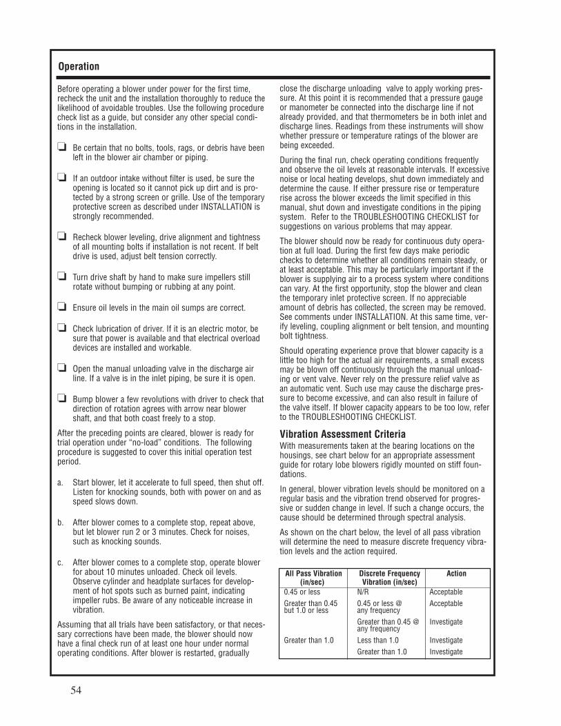
Vibration Assessment CriteriaWith measurements taken at the bearing locations on thehousings, see chart below for an appropriate assessmentguide for rotary lobe blowers rigidly mounted on stiff foun-dations.
In general, blower vibration levels should be monitored on aregular basis and the vibration trend observed for progres-sive or sudden change in level. If such a change occurs, thecause should be determined through spectral analysis.
As shown on the chart below, the level of all pass vibrationwill determine the need to measure discrete frequency vibra-tion levels and the action required.
Operation
All Pass Vibration Discrete Frequency Action(in/sec) Vibration (in/sec)
0.45 or less N/R Acceptable
Greater than 0.45 0.45 or less @ Acceptablebut 1.0 or less any frequency
Greater than 0.45 @ Investigateany frequency
Greater than 1.0 Less than 1.0 Investigate
Greater than 1.0 Investigate
54
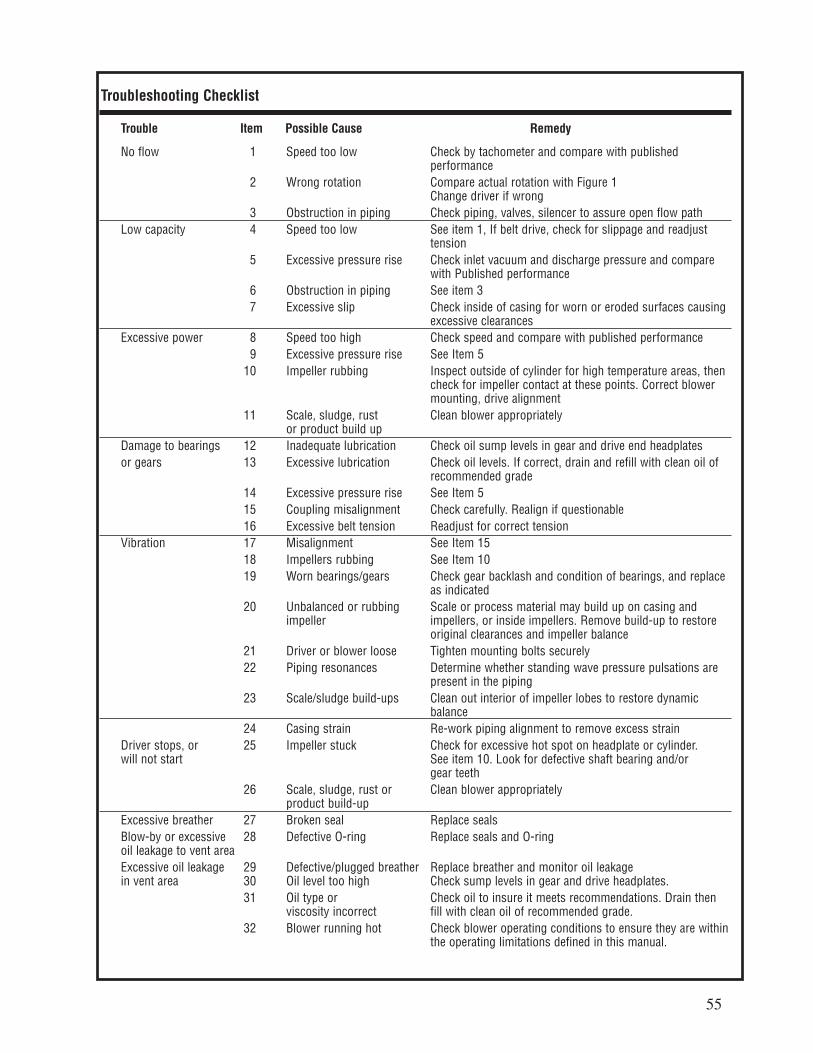
Troubleshooting Checklist
Trouble Item Possible Cause Remedy
No flow 1 Speed too low Check by tachometer and compare with published performance
2 Wrong rotation Compare actual rotation with Figure 1Change driver if wrong
3 Obstruction in piping Check piping, valves, silencer to assure open flow path
Low capacity 4 Speed too low See item 1, If belt drive, check for slippage and readjust tension
5 Excessive pressure rise Check inlet vacuum and discharge pressure and comparewith Published performance
6 Obstruction in piping See item 3
7 Excessive slip Check inside of casing for worn or eroded surfaces causing excessive clearances
Excessive power 8 Speed too high Check speed and compare with published performance
9 Excessive pressure rise See Item 5
10 Impeller rubbing Inspect outside of cylinder for high temperature areas, thencheck for impeller contact at these points. Correct blower mounting, drive alignment
11 Scale, sludge, rust Clean blower appropriatelyor product build up
Damage to bearings 12 Inadequate lubrication Check oil sump levels in gear and drive end headplates
or gears 13 Excessive lubrication Check oil levels. If correct, drain and refill with clean oil of recommended grade
14 Excessive pressure rise See Item 5
15 Coupling misalignment Check carefully. Realign if questionable
16 Excessive belt tension Readjust for correct tension
Vibration 17 Misalignment See Item 15
18 Impellers rubbing See Item 10
19 Worn bearings/gears Check gear backlash and condition of bearings, and replace as indicated
20 Unbalanced or rubbing Scale or process material may build up on casing and impeller impellers, or inside impellers. Remove build-up to restore
original clearances and impeller balance
21 Driver or blower loose Tighten mounting bolts securely
22 Piping resonances Determine whether standing wave pressure pulsations are present in the piping
23 Scale/sludge build-ups Clean out interior of impeller lobes to restore dynamic balance
24 Casing strain Re-work piping alignment to remove excess strain
Driver stops, or 25 Impeller stuck Check for excessive hot spot on headplate or cylinder.will not start See item 10. Look for defective shaft bearing and/or
gear teeth
26 Scale, sludge, rust or Clean blower appropriatelyproduct build-up
Excessive breather 27 Broken seal Replace seals
Blow-by or excessive 28 Defective O-ring Replace seals and O-ringoil leakage to vent area
Excessive oil leakage 29 Defective/plugged breather Replace breather and monitor oil leakagein vent area 30 Oil level too high Check sump levels in gear and drive headplates.
31 Oil type or Check oil to insure it meets recommendations. Drain thenviscosity incorrect fill with clean oil of recommended grade.
32 Blower running hot Check blower operating conditions to ensure they are withinthe operating limitations defined in this manual.
55

Inspection & Maintenance: Universal RAI® series blowers
A good program of consistent inspection and maintenance isthe most reliable method of minimizing repairs to a blower. Asimple record of services and dates will help keep this workon a regular schedule. Basic service needs are:
• Lubrication
• Checking for hot spots
• Checking for increases or changes in vibration and noise
• Recording of operating pressures and temperatures
Above all, a blower must be operated within its specified rat-ing limits, to obtain satisfactory service life.
A newly installed blower should be checked often during thefirst month of full-time operation. Attention there after maybe less frequent assuming satisfactory performance.Lubrication is normally the most important consideration andweekly checks of lubricant levels in the gearbox and bearingreservoirs should be customary. Complete oil change sched-ules are discussed under LUBRICATION.
Driver lubrication practices should be in accordance with themanufacturer’s instructions. If direct connected to the blowerthrough a lubricated type coupling, the coupling should bechecked and greased each time blower oil is changed. Thiswill help reduce wear and prevent unnecessary vibration. In abelted drive system, check belt tension periodically andinspect for frayed or cracked belts.
In a new, and properly installed, unit there is no contactbetween the two impellers, or between the impellers andcylinder or headplates. Wear is confined to the bearings(which support and locate the shafts) the oil seals, and thetiming gears. All are lubricated and wear should be minimalif clean oil of the correct grade is always used. Seals are sub-ject to deterioration as well as wear, and may require replace-ment at varying periods.
Shaft bearings are designed for optimum life under averageconditions with proper lubrication and are critical to the serv-ice life of the blower. Gradual bearing wear may allow a shaftposition to change slightly, until rubbing develops betweenimpeller and casing. This will cause spot heating, which canbe detected by observing these surfaces. Sudden bearingfailure is usually more serious. Since the shaft and impellerare no longer supported and properly located, extensive gen-eral damage to the blower casing and gears is likely to occur.
Oil seals should be considered expendable items, to bereplaced whenever drainage from the headplate vent cavitybecomes excessive or when the blower is disassembled for
any reason. Some oil seal leakage may occur since an oil filmunder the lip is required for proper operation. Periodicallyleaked oil should be wiped off from surfaces. Minor sealleakage should not be considered as indicating seal replace-ment.
Timing gear wear, when correct lubrication is maintained,should be negligible. Gear teeth are cut to provide the correctamount of backlash, and gears correctly mounted on theshafts will accommodate a normal amount of tooth wearwithout permitting contact between lobes of the twoimpellers. However, too high an oil level will cause churningand excessive heating. This is indicated by unusually hightemperature at the bottom of the gear housing. Consequentheating of the gears will result in loss of tooth-clearance ,backlash and rapid wear of the gear teeth usually will devel-op. Continuation of this tooth wear will eventually produceimpeller contacts (knocking), and from this point seriousdamage will be unavoidable if blower operation is continued.A similar situation can be produced suddenly by gear toothfracture, which is usually brought on by sustained overload-ing or momentary shock loads.
Problems may also develop from causes other than internalparts failure. Operating clearances within a blower are only afew thousandths of an inch. This makes it possible forimpeller interference or casing rubs to result from shifts inthe blower mounting, or from changes in piping support. Ifthis type of trouble is experienced, and the blower is foundto be clean, try removing mounting strains. Loosen blowermounting bolts and reset the leveling and drive alignment.Then tighten mounting again, and make sure that all pipingmeets blower connections accurately and squarely Foreignmaterials in the blower will also cause trouble, which canonly be cured by disconnecting the piping and thoroughlycleaning the blower interior.
A wide range of causes & solutions for operating troublesare covered in the TROUBLE SHOOTING CHECKLIST. Theremedies suggested should be performed by qualifiedmechanics with a good background. Major repairs generallyare to be considered beyond the scope of maintenance, andshould be referred to an authorized Roots distributor.
Warranty failures should not be repaired at all, unless specif-ic approval has been obtained through Roots before startingwork. Unauthorized disassembly within the warranty periodmay void the warranty.
56
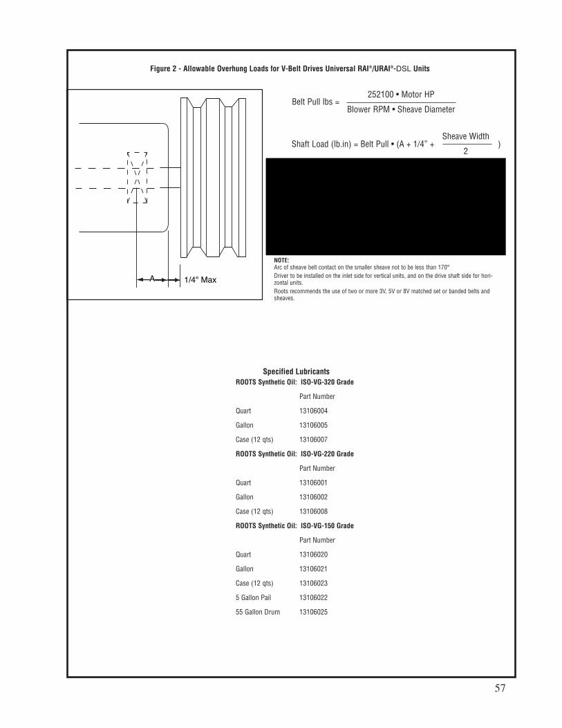
Figure 2 - Allowable Overhung Loads for V-Belt Drives Universal RAI®/URAI®-DSL Units
A 1/4" Max
Belt Pull lbs =252100 • Motor HP
Blower RPM • Sheave Diameter
Frame Dimension Max Allowable Min SheaveSize “A” Shaft Load (lb-in.) Diameter
22, 24 0.61 150 4.00
32, 33, 36 0.80 400 5.00
42, 45, 47 1.02 650 5.00
53, 56, 59 1.13 1,325 6.00
65, 68, 615 1.36 2,250 8.00
76, 711, 718 1.16 2,300 9.50
NOTE:Arc of sheave belt contact on the smaller sheave not to be less than 170°
Driver to be installed on the inlet side for vertical units, and on the drive shaft side for hori-zontal units.
Roots recommends the use of two or more 3V, 5V or 8V matched set or banded belts andsheaves.
Shaft Load (lb.in) = Belt Pull • (A + 1/4” + )Sheave Width
2
Frame Dimension Max Allowable Min Sheave
Size "A" Shaflt Load (lb-in) Diameter
47 1.02 650 5.00
Specified Lubricants
ROOTS Synthetic Oil: ISO-VG-320 Grade
Part Number
Quart 13106004
Gallon 13106005
Case (12 qts) 13106007
ROOTS Synthetic Oil: ISO-VG-220 Grade
Part Number
Quart 13106001
Gallon 13106002
Case (12 qts) 13106008
ROOTS Synthetic Oil: ISO-VG-150 Grade
Part Number
Quart 13106020
Gallon 13106021
Case (12 qts) 13106023
5 Gallon Pail 13106022
55 Gallon Drum 13106025
57

Table 1 - URAI, URAI-DSL Blowers, Maximum Allowable Operating Conditions
Drive End Breather Orientation for URA-DSL blowers with Oil Lube
Frame Gear Speed Temp. Rise Delta Pressure Inlet Vacuum
Size Diameter (Inch) RPM Deg F (Deg C) PSI (mbar) INHG (mbar)
47 4 3,600 225 (125) 7 (483) 15 (500)
58

Ambient ISOTemperature °F (°C) Viscosity No.
Above 90° (32°) 320
32° to 90° (0° to 32°) 220
0° to 32° (-18° to 0°) 150
Below 0° (-18°) 100
Table 2 - Recommended Oil Grades
Table 3 - Approximate Oil Sump Capacities
These capacities are provided to assist in stocking the correct amount of oil. Exact sump capacities may differ slightly. See“Lubrication” section for proper filling instructions.
Ambient temperature is defined as the temperature of the space inwhich the blower and drive are located.
Frame Gear End Capacity Drive End Capaicty
Size Fl. Oz (Liters) Fl. Oz. (Liters)
47 22.8 (.67) 10.8 (.32)
URAI-DSL Splash Lubricated Blowers
Refer to Specification Sheet S-27S03
Universal RAI air blowers include detachable mounting feet which permit vertical or horizontal installation.
The units are center timed for rotation in either direction. The bearings on the URAI are grease lubricated
on the drive end and splash lubricated on the gear end. The URAI-DSL is splash lubricated on BOTH ends.
BOM# FRAME INLET/DISCHARGE SHAFT BARE
SIZE CONN. DIAMETER WEIGHT
T30354020 47 3" NPT .0875" 132
URAI DSL AIR BLOWERS (with Dual Splash Lubrication DSL)
Basic Connection & Drive Shaft Information
59

LIMITED WARRANTYThe Manufacturer warrants its products to be free from defects in material and workmanship for a period of twelvemonths from the date of shipment from the factory. The Manufacturer shall not be responsible for any damageresulting to or caused by its products by reason of installation, improper storage, unauthorized service, alterationof the products, neglect or abuse, or use of the product in a manner inconsistent with its design. The warrantydoes not extend to any component parts not manufactured by Manufacturer; however, Manufacturer’s warrantyherein shall not limit any warranties made by manufacturers of component parts which extend to Buyer.
Claims for defects in material and workmanship shall be made in writing to Manufacturer within ten days ofdiscovery of defect. Manufacturer may either send a service representative or have the product returned to itsfactory at Buyer’s expense for inspection. Upon notification of defect, Manufacturer will issue a return goodsauthorization number to Buyer. The return goods authorization number must accompany the product returned. Ifjudged by the Manufacturer to be defective in material or workmanship, the product will be replaced or repaired atthe option of the Manufacturer, free from all charges except authorized transportation. Buyer shall be responsiblefor all maintenance services consisting of lubrication and cleaning of equipment, replacing expandable parts,making minor adjustments, and performing operating checks, all in accordance with procedures outlined inManufacturer’s maintenance literature.
THE FOREGOING WARRANTY IS IN LIEU OF ALL OTHER WARRANTIES AND NO REPRESENTATIONS,GUARANTEES, OR WARRANTIES, EXPRESS OR IMPLIED, (INCLUDING BUT NOT LIMITED TO A WARRANTYOF MERCHANTABILITY OR FITNESS FOR A PARTICULAR PURPOSE), ARE MADE BY THE MANUFACTURERIN CONNECTION WITH THE MANUFACTURE OR SALE OF ITS PRODUCTS. NO EMPLOYEE, DISTRIBUTOR,OR REPRESENTATIVE IS AUTHORIZED TO CHANGE THIS WARRANTY ON BEHALF OF MANUFACTURER.THE REMEDIES OF BUYER SET FORTH HEREIN ARE EXCLUSIVE AND ARE IN LIEU OF ALL OTHER REM-EDIES. THE LIABILITY OF MANUFACTURER WHETHER IN CONTRACT, TORT, UNDER ANY WARRANTY, OROTHERWISE SHALL NOT EXTEND BEYOND ITS OBLIGATION TO REPAIR OR REPLACE, AT ITS OPTION ANYPRODUCT OR PART FOUND BY MANUFACTURER TO BE DEFECTIVE IN MATERIAL OR WORKMANSHIP.MANUFACTURER SHALL NOT BE LIABLE FOR COST OF INSTALLATION AND/OR REMOVAL OR BE RE-SPONSIBLE FOR DIRECT, INDIRECT, SPECIAL OR CONSEQUENTIAL DAMAGES OF ANY NATURE.
GENERAL RETURNS OF MERCHANDISE1. All returns must be pre-authorized
A. Please call our parts department for an RGA numberB. Please include RGA number on the outside of boxC. Include any required paper work or special instructionsD. Items returned without an RGA number will not be accepted
2. All returns are subject to a 20% restock charge.3. Special items are non-returnable
A. Non-stock partsB. Custom partsC. If you are unsure about a parts status when ordering, ask your McLaughlin representative if the itemfits on of the above conditions.
4. Items must be returned within thirty days of original order date.5. Items not returned within 30 days from the date of RGA is issued will not be accepted.
6. The item(s) must be in new condition. Used item(s) are not returnable.
WARRANTYRETURN GOODS POLICY

Maintenance RecordDATE SERVICE PERFORMED BY________ _______________________________________ _________________________
________ _______________________________________ _________________________
________ _______________________________________ _________________________
________ _______________________________________ _________________________
________ _______________________________________ _________________________
________ _______________________________________ _________________________
________ _______________________________________ _________________________
________ _______________________________________ _________________________
________ _______________________________________ _________________________
________ _______________________________________ _________________________
________ _______________________________________ _________________________
________ _______________________________________ _________________________
________ _______________________________________ _________________________
________ _______________________________________ _________________________
________ _______________________________________ _________________________
________ _______________________________________ _________________________
________ _______________________________________ _________________________
________ _______________________________________ _________________________
________ _______________________________________ _________________________
________ _______________________________________ _________________________
________ _______________________________________ _________________________
________ _______________________________________ _________________________
________ _______________________________________ _________________________
________ _______________________________________ _________________________
________ _______________________________________ _________________________
________ _______________________________________ _________________________
________ _______________________________________ _________________________
________ _______________________________________ _________________________

_______________________________________________________________________________________________________________________________________
_________________________________________________________________________
_________________________________________________________________________
________________________________________________________________________
________________________________________________________________________
_________________________________________________________________________
________________________________________________________________________
________________________________________________________________________
________________________________________________________________________
________________________________________________________________________
________________________________________________________________________
_____________________________________________________________________________________________________________________________________________________________________________________________________________________________________________________________________________________________________________________________________________________________________________________________________________________________________________________________________________________________________________________________________________________________________________________________________________________________________________________________________________________________________________________________________________________________________________________________________________________________________________________________________________________________________________________________________________________________________________________________________________________________________________________________________________________________________________________________________________________________________________________________________________________________________________________________________________________________________________________________________________________________________________________________________________________________
________________________________________________________________________
_______________________________________________________________________________________________________________________________________________________________________________________________________________________________________________________________________________________
________________________________________________________________________
_________________________________________________________________________________________________________________________________________________________________________________________________________________________
________________________________________________________________________
_________________________________________________________________________________________________________________________________________________
________________________________________________________________________________________________________________________________________________
________________________________________________________________________
Notes
