parts list dakar pro brackets part 2014 ... - go rhino · step-6 adjust the mounting plate/winch...
TRANSCRIPT

REV. DATE: 7/16/2016 Page 1 of 10
Parts List
Item Qty. Part # Description Item Qty. Part # Description Torque
1 1 24219T Bumper Replacement Shell 13 4 Nut-Plate
2 2 Frame Bracket 14 22 ½” x 1 ½” Hex Bolt 64 ft. lbs.
3 1 Driver Auxiliary Bracket 15 6 ½” x 1 ½” Carriage Bolt 64 ft. lbs.
4 1 Passenger Auxiliary Bracket 16 36 ½” Flat Washer
5 1 Driver Support Bracket 17 28 ½” Lock Washer
6 1 Passenger Support Bracket 18 14 ½” Hex Nut
7 1 Driver Vent Cover 19 2 3/8” x 1 ¼” Hex Bolt 26 ft. lbs.
8 1 Passenger Vent Cover 20 2 3/8” Lock Washer
9 1 Winch Cover 21 2 3/8” Flat Washer
10 2 Light Pod Plate 22 2 3/8” Hex Nut
11 1 License Plate Bracket 23 38 ¼” x ¾” Button Head Bolt 71 in. lbs.
24 10 ¼” Nylon Lock Nut
Required for Installation (Sold Separately) 25 4 Hole Plug
12 1 24473TW Mounting Plate/Winch Tray
Installation Instructions BR10 Front Bumper Replacement Part Number 24219T
2010-2016 Ram HD 2500 & 3500 2/4WD Do not attempt to install this product on any vehicle other than the one listed above!
DAKAR PRO Brackets Part # 524765
2014 Chevrolet Silverado 1500 2/4WD Do not attempt to install this product on any vehicle other than the one listed above!
Tool Required:
10mm, 13mm, 15mm, 18mm, 24mm, 7/16”, 9/16” & 3/4” Sockets 10mm, 13mm, 15mm, 18mm, 24mm, 7/16”, 9/16” & 3/4” Wrenches Slotted Blade Screw Driver 5/32” Hex Key Ratchet, Ratchet Extensions & Swivel Joint Adapter Approximate installation time: 2 hrs.
1
3
7
4
2
6 8
5
10
ILLUSTRATION #1
9
2
12

REV. DATE: 7/16/2016 Page 2 of 10
IMPORTANT INSTALLATION NOTES AND SUGGESTIONS
The pre-installed Mesh Winch and Vent Covers need to be removed using hand tools to slowly remove the bolts. Using an air assisted impact or ratchet will damage the bolt threads and the internal nut assembly in the bumper shell. Use of an appropriate anti-seize compound is highly recommended for re-installation, and tighten the bolts to the specified torque as overtightening could result in difficulty of future removal.
If your vehicle does not have the under rider brackets and the attachment holes in the frame rails, drilling holes in the frame rails to attach the bumper replacement auxiliary and support brackets is required. Reference the diagram, and transfer the measurements on the outside of the driver and passenger side frame rails.
To maintain and care this product keep it clean and do not use abrasive cleaners or polish waxes. Texture Painted Finish: Mild liquid detergent may be used. Polished Stainless & Semi-Gloss Painted Finishes: We recommend using only non-abrasive automotive wax such as pure carnauba to avoid scratches and rust.
Read the installation instructions completely and verify that all of the parts listed are accounted for. If you have defective, missing or damaged parts or need assistance, please contact Go Rhino Products for fast, friendly customer service at: (888) 427-4466 or email: [email protected]
Transfer the measurements from the diagram to the outside of the driver and passenger side frame rails. From the outside of the frame rail drill 5/8” holes through both sides of the frame rail.
Under Rider Bracket
REV. DATE: 7/16/2016 Page 3 of 10
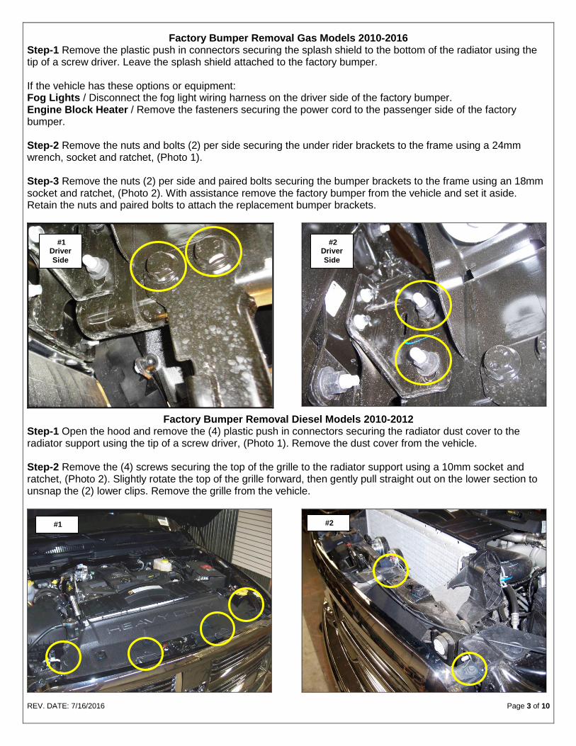
Factory Bumper Removal Gas Models 2010-2016
Step-1 Remove the plastic push in connectors securing the splash shield to the bottom of the radiator using the tip of a screw driver. Leave the splash shield attached to the factory bumper. If the vehicle has these options or equipment: Fog Lights / Disconnect the fog light wiring harness on the driver side of the factory bumper. Engine Block Heater / Remove the fasteners securing the power cord to the passenger side of the factory bumper. Step-2 Remove the nuts and bolts (2) per side securing the under rider brackets to the frame using a 24mm wrench, socket and ratchet, (Photo 1). Step-3 Remove the nuts (2) per side and paired bolts securing the bumper brackets to the frame using an 18mm socket and ratchet, (Photo 2). With assistance remove the factory bumper from the vehicle and set it aside. Retain the nuts and paired bolts to attach the replacement bumper brackets.
Factory Bumper Removal Diesel Models 2010-2012 Step-1 Open the hood and remove the (4) plastic push in connectors securing the radiator dust cover to the radiator support using the tip of a screw driver, (Photo 1). Remove the dust cover from the vehicle. Step-2 Remove the (4) screws securing the top of the grille to the radiator support using a 10mm socket and ratchet, (Photo 2). Slightly rotate the top of the grille forward, then gently pull straight out on the lower section to unsnap the (2) lower clips. Remove the grille from the vehicle.
#1 #2
#1 Driver
Side
#2 Driver
Side

REV. DATE: 7/16/2016 Page 4 of 10
Step-3 Remove the (2) plastic push in connectors securing the radiator shield to the radiator support using the tip of a screw driver and the bolts (1) per side securing the top of the intercooler to the radiator support using a 13mm socket and ratchet, (Photo 3). If the vehicle has these options or equipment: Fog Lights / Disconnect the fog light wiring harness on the driver side of the factory bumper. Engine Block Heater / Remove the fasteners securing the power cord to the passenger side of the factory bumper. Step-4 Remove the (4) plastic push in connectors securing the splash shield to the bottom of the radiator using the tip of a screw driver. Leave the splash shield attached to the factory bumper, (Photo 4).
Step-5 Remove the nuts and bolts (2) per side securing the under rider brackets to the frame using a 24mm wrench, socket and ratchet, (Photo 5).
Step-6 Remove the nuts (2) per side and paired bolts securing the bumper brackets to the frame using an 18mm socket and ratchet, (Photo 6). With assistance remove the factory bumper from the vehicle and set it aside. Retain the nuts and paired bolts to attach the replacement bumper brackets. Note: Slightly lift the intercooler and move it to one side at a time to remove the paired bolts.
#3 Driver
Side
#4
#5 Driver
Side
#6 Driver
Side

REV. DATE: 7/16/2016 Page 5 of 10
Factory Bumper Removal Diesel Models 2013-2016 Step-1 Open the hood and remove the (4) plastic push in connectors securing the radiator dust cover to the radiator support using the tip of a screw driver, (Photo 1). Remove the dust cover from the vehicle. Step-2 Remove the (4) screws securing the top of the grille to the radiator support using a 10mm socket and ratchet, (Photo 2). Slightly rotate the top of the grille forward, then gently pull straight out on the lower section to unsnap the (2) lower clips. Remove the grille from the vehicle.
Step-3 Remove the (3) plastic push in connectors securing the splash shield to the bottom of the radiator using the tip of a screw driver. Leave the splash shield attached to the factory bumper, (Photo 3). If the vehicle has these options or equipment: Fog Lights / Disconnect the fog light wiring harness on the driver side of the factory bumper, (Photo 4). Engine Block Heater / Remove the fasteners securing the power cord to the passenger side of the factory bumper.
#3
#1 #2
#4 Driver
Side
REV. DATE: 7/16/2016 Page 6 of 10
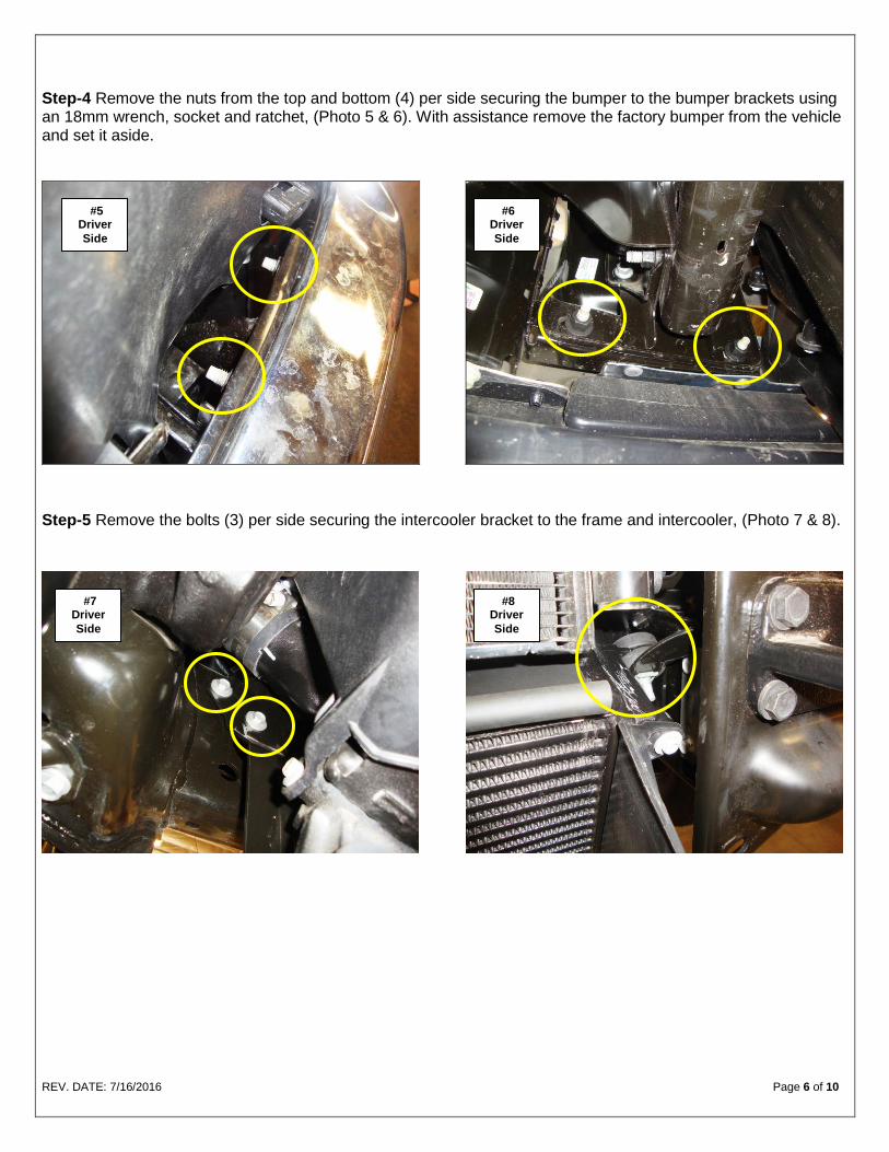
Step-4 Remove the nuts from the top and bottom (4) per side securing the bumper to the bumper brackets using an 18mm wrench, socket and ratchet, (Photo 5 & 6). With assistance remove the factory bumper from the vehicle and set it aside.
Step-5 Remove the bolts (3) per side securing the intercooler bracket to the frame and intercooler, (Photo 7 & 8).
#6 Driver
Side
#8 Driver
Side
#5 Driver
Side
#7 Driver
Side
REV. DATE: 7/16/2016 Page 7 of 10
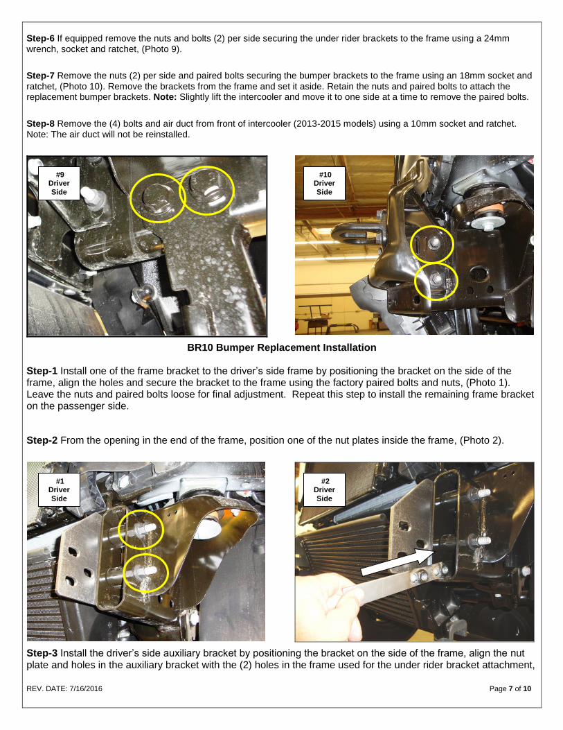
Step-6 If equipped remove the nuts and bolts (2) per side securing the under rider brackets to the frame using a 24mm wrench, socket and ratchet, (Photo 9).
Step-7 Remove the nuts (2) per side and paired bolts securing the bumper brackets to the frame using an 18mm socket and ratchet, (Photo 10). Remove the brackets from the frame and set it aside. Retain the nuts and paired bolts to attach the replacement bumper brackets. Note: Slightly lift the intercooler and move it to one side at a time to remove the paired bolts.
Step-8 Remove the (4) bolts and air duct from front of intercooler (2013-2015 models) using a 10mm socket and ratchet. Note: The air duct will not be reinstalled.
BR10 Bumper Replacement Installation Step-1 Install one of the frame bracket to the driver’s side frame by positioning the bracket on the side of the frame, align the holes and secure the bracket to the frame using the factory paired bolts and nuts, (Photo 1). Leave the nuts and paired bolts loose for final adjustment. Repeat this step to install the remaining frame bracket on the passenger side.
Step-2 From the opening in the end of the frame, position one of the nut plates inside the frame, (Photo 2).
Step-3 Install the driver’s side auxiliary bracket by positioning the bracket on the side of the frame, align the nut plate and holes in the auxiliary bracket with the (2) holes in the frame used for the under rider bracket attachment,
#9 Driver
Side
#10 Driver
Side
#1 Driver
Side
#2 Driver
Side
REV. DATE: 7/16/2016 Page 8 of 10
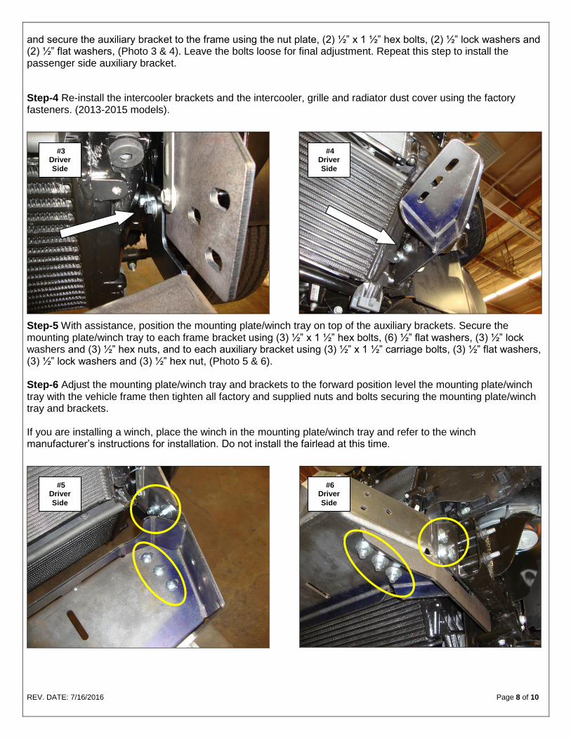
and secure the auxiliary bracket to the frame using the nut plate, (2) ½” x 1 ½” hex bolts, (2) ½” lock washers and (2) ½” flat washers, (Photo 3 & 4). Leave the bolts loose for final adjustment. Repeat this step to install the passenger side auxiliary bracket.
Step-4 Re-install the intercooler brackets and the intercooler, grille and radiator dust cover using the factory fasteners. (2013-2015 models).
Step-5 With assistance, position the mounting plate/winch tray on top of the auxiliary brackets. Secure the mounting plate/winch tray to each frame bracket using (3) ½” x 1 ½” hex bolts, (6) ½” flat washers, (3) ½” lock washers and (3) ½” hex nuts, and to each auxiliary bracket using (3) ½” x 1 ½” carriage bolts, (3) ½” flat washers, (3) ½” lock washers and (3) ½” hex nut, (Photo 5 & 6). Step-6 Adjust the mounting plate/winch tray and brackets to the forward position level the mounting plate/winch tray with the vehicle frame then tighten all factory and supplied nuts and bolts securing the mounting plate/winch tray and brackets. If you are installing a winch, place the winch in the mounting plate/winch tray and refer to the winch manufacturer’s instructions for installation. Do not install the fairlead at this time.
#3 Driver
Side
#4 Driver
Side
#5 Driver
Side
#6 Driver
Side

REV. DATE: 7/16/2016 Page 9 of 10
Step-7 With assistance lift the bumper shell up to the vehicle, align the holes in the bumper shell brackets with the weld nuts on the mounting plate/winch tray and secure the bumper shell to each side of the mounting plate/winch tray using (3) ½” x 1 1/2” hex bolts, (3) ½” lock washers and (3) ½” flat washers, (Photo 7 & 8). Leave the bolts loose for final adjustment.
Step-8 With assistance, adjust and hold the bumper shell visual alignment position, then tighten all factory and supplied nuts and bolts. Note: It may be necessary to loosen the nuts and bolts securing the mounting plate/winch tray and brackets.
If installing a winch, install the roller fairlead to the bumper shell at this time. Refer to the winch manufacturer’s instructions for installation. If installing an optional light bar, install the light bar to the bumper replacement at this time. Refer to the light bar instructions for installation.
#7 Driver
Side
#8 Driver
Side
REV. DATE: 7/16/2016 Page 10 of 10
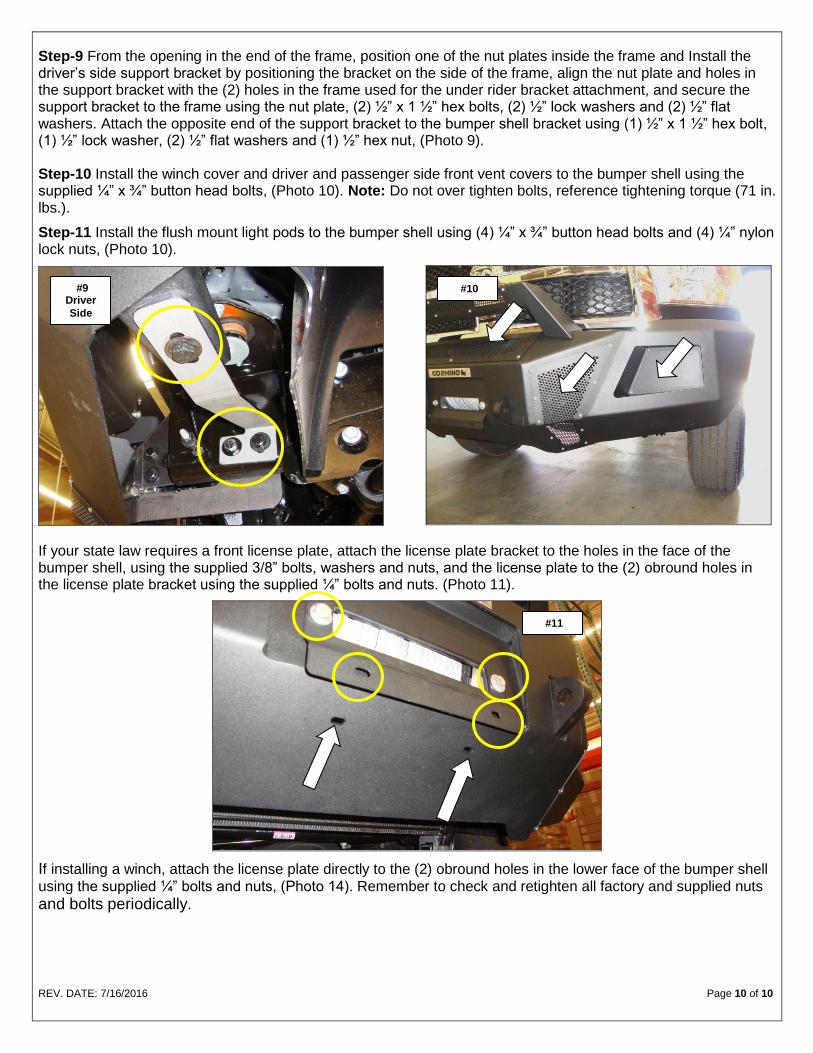
Step-9 From the opening in the end of the frame, position one of the nut plates inside the frame and Install the driver’s side support bracket by positioning the bracket on the side of the frame, align the nut plate and holes in the support bracket with the (2) holes in the frame used for the under rider bracket attachment, and secure the support bracket to the frame using the nut plate, (2) ½” x 1 ½” hex bolts, (2) ½” lock washers and (2) ½” flat washers. Attach the opposite end of the support bracket to the bumper shell bracket using (1) ½” x 1 ½” hex bolt, (1) ½” lock washer, (2) ½” flat washers and (1) ½” hex nut, (Photo 9). Step-10 Install the winch cover and driver and passenger side front vent covers to the bumper shell using the supplied ¼” x ¾” button head bolts, (Photo 10). Note: Do not over tighten bolts, reference tightening torque (71 in. lbs.).
Step-11 Install the flush mount light pods to the bumper shell using (4) ¼” x ¾” button head bolts and (4) ¼” nylon lock nuts, (Photo 10).
\
If your state law requires a front license plate, attach the license plate bracket to the holes in the face of the bumper shell, using the supplied 3/8” bolts, washers and nuts, and the license plate to the (2) obround holes in the license plate bracket using the supplied ¼” bolts and nuts. (Photo 11).
If installing a winch, attach the license plate directly to the (2) obround holes in the lower face of the bumper shell
using the supplied ¼” bolts and nuts, (Photo 14). Remember to check and retighten all factory and supplied nuts
and bolts periodically.
#9 Driver
Side
#10
#11