parts information - eatonpub/@eaton/@hyd/...7 model 70160 parts list 37 70111-667 1 9 tooth coupler...
TRANSCRIPT

Eaton®
Medium Duty Piston Pump
Model 70160 Variable Displacement Piston Pump20,3 cm3/r [1.24 in3/r] or 23,6 cm3/r [1.44 in3/r] DisplacementsManual Controlled v-02
Parts Information

2
Model 70160
3
Model 70160
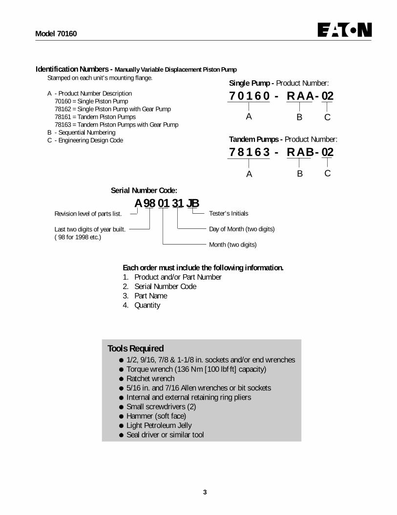
Tools Required1/2, 9/16, 7/8 & 1-1/8 in. sockets and/or end wrenchesTorque wrench (136 N.m [100 lbf.ft] capacity)Ratchet wrench5/16 in. and 7/16 Allen wrenches or bit socketsInternal and external retaining ring pliersSmall screwdrivers (2)Hammer (soft face)Light Petroleum JellySeal driver or similar tool
Single Pump - Product Number:
7 0 1 6 0 - R A A - 02
Tandem Pumps - Product Number:
7 8 1 6 3 - R A B - 02
Serial Number Code:
A 98 01 31 JBTester's Initials
Day of Month (two digits)
Month (two digits)
Revision level of parts list.
Last two digits of year built.( 98 for 1998 etc.)
Identification Numbers - Manually Variable Displacement Piston PumpStamped on each unit's mounting flange.
A - Product Number Description70160 = Single Piston Pump78162 = Single Piston Pump with Gear Pump78161 = Tandem Piston Pumps78163 = Tandem Piston Pumps with Gear Pump
B - Sequential NumberingC - Engineering Design Code
A
A
B
B
Each order must include the following information.1. Product and/or Part Number2. Serial Number Code3. Part Name4. Quantity
C
C

4
Model 70160
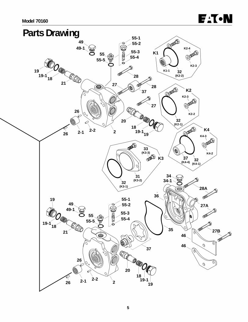
Parts Drawing
Pump drawn below is typical of a right hand pump.
30
3-1Press Fit
6
5
4
1
Shaft assembly for rear pump of tandem.
Shaft assembly for single pump or front pump of tandem.
1
7
7
8
8
8
89
1010
910
10
11
11
29
48
12
24
41
16 Press Fit
23
17
17
14
3
5050-1
51
22 Press Fit
22 Press Fit
51-1
13
14
4039
41
Port(D2)
Port(D1)
39Press Fit into Cover plate
5
Model 70160
22-1 2-226
26
21
20
18
1919-1
1919-1
18
27
27
28
2837
37(K4-4)
2-1 2-226
26
21
20
18
19
19-1
1919-1
182
27A
27B
28A
55-149 55-2
55-355-4
49-155
55-5
37
35
36
55-1
55
55-2
55-355-4
55-5
4949-1
3434-1
32(K2-1)
K2-2
K2-3
32(K3-1)
31(K3-2)
33(K3-3)
K3
K2
32(K4-1)
K4-2
K4-3
K4
K1-1 32(K2-2)
K2-3
K2-4
K1
46
46
Parts Drawing

6
Model 70160
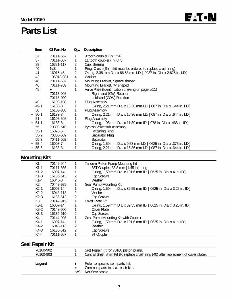
Item 02 Part No. Qty. Description1 ♦ 1 Drive Shaft (Identification drawing on page #8)2 ♦ 1 Endcover Assembly (Identification drawing and parts list on page #9)3 ♦ 1 Housing Assembly (Identification drawing on page #10)3-1 16238-11616 1 Bearing (Press Fit)4 70111-692 1 Rotating Kit Assembly (parts list on page #10)5 1 Swashplate, 20,3 cm3/r [1.24 in3/r] Displacement
70160-623 Square Arm70160-617 Tapered Arm
5 1 Swashplate, 23,6 cm3/r [1.44 in3/r] Displacement70160-620 Square Arm70160-618 Tapered Arm
6 16048-312 1 Washer+ 7 16077-26 1 Retaining Ring+ 8 16078-16 2 Retaining Ring
9 16241-1625 1 Thrust Bearing10 16241-C1625 2 Bearing Race
+ 11 16253-16 1 Shaft Seal, Drive11 16253-216 1 Viton Shaft Seal, Drive11 70102-636 1 Spacer
+ 12 70111-701 1 Housing Gasket13 70160-504 1 Swashplate Insert14 106013-038 6 Washer
+ 16 16253-214 1 Shaft Seal, Trunnion17 16136-610 6 Screw, Cap18 17086-017 2 Spring19 32060-8 2 Plug Assembly
+ 19-1 16015-18-90 2 O-ring, 2,38 mm Dia. x 22,23 mm ID. [.0937 in. Dia. x .875 in. ID.]20 ♦ 1 Relief Valve for Port "C" (Identification drawing on page #11)21 ♦ 1 Relief Valve for Port "D" (Identification drawing on page #11)22 16320-117 2 Cone Bearing23 70160-508 1 Cover Plate24 70160-510 1 Cover Plate26 16028-304 2 Dowel Pin27 16136-520 2 Cap Screws, 5/16-18, 50,8 mm [2 in.] Long27A 16136-532 2 Cap Screws, 5/16-18, 82,6 mm [3.25 in.] Long27B 16136-534 2 Cap Screws, 5/16-18, 88,9 mm [3.5 in.] Long28 16136-524 2 Cap Screws, 5/16-18, 63,5 mm [2.5 in.] Long28A 16136-536 2 Cap Screws, 5/16-18, 95,3 mm [3.75 in.] Long28B 16136-540 2 Cap Screws, 5/16-18, 101,6 mm [4.00 in.] Long29 1 Key, Drive Shaft
24500-619 Used with 7/8 in. dia. drive shaft.30 16246-430 1 Key, Tapered Arm31 70142-600 1 Cover Plate (In K3 kit)
+ 32 16007-14 1 O-ring (In K1, K2, K3, & K4 kit)33 16036-610 2 Cap Screws, Cover Plate (In K3 kit)34 16103-108 1 Plug Assembly
+ 34-1 16133-8 1 O-ring, 2,21 mm Dia. x 16,36 mm ID. [.087 in. Dia. x .644 in. ID.]+ 35 70111-703 1 Molded O-ring
36 ♦ 1 Charge Pump Adaptor (Identification drawing and parts list on page #12 & #13)37 1 Gerotor set and coupler sub-assembly
70111-642 6,9 cm3/r [.42 in3/r] displacement, 6,35 mm [.25 in ] width70111-646 13,8 cm3/r [.84 in3/r] displacement, 12,7 mm [.5 in] width
Parts ListParts listed below are to service catalog units. Other variations of units are built that have parts altered for special requirements.The non-catalog units can be serviced with the parts list below using caution for proper identification. Contact an Eatonrepresentative with any questions concerning your selection. Have your final assembly number ready when contactingrepresentative.
7
Model 70160
Parts List
37 70111-667 1 9 tooth coupler (In Kit 4)37 70111-687 1 11 tooth coupler (In Kit 5)39 16321-117 2 Cup, Bearing40 N/S 1 Ring, Crush (Shim kit must be ordered to replace crush ring).41 16015-46 2 O-ring, 2.38 mm Dia. x 66.68 mm I.D. [.0937 in. Dia. x 2.625 in. I.D.]42 106013-031 4 Washer46 70111-632 1 Mounting Bracket, Square shaped46 70111-709 1 Mounting Bracket, "V" shaped48 ♦ 1 Valve Plate (Identification drawing on page #11)
70113-008 Righthand (CW) Rotation70113-009 Lefthand (CCW) Rotation
+ 49 16103-108 1 Plug Assembly49-1 16133-8 1 O-ring, 2,21 mm Dia. x 16,36 mm I.D. [.087 in. Dia. x .644 in. I.D.]50 16103-308 1 Plug Assembly
+ 50-1 16133-8 1 O-ring, 2,21 mm Dia. x 16,36 mm I.D. [.087 in. Dia. x .644 in. I.D.]51 16103-308 1 Plug Assembly
+ 51-1 16133-8 1 O-ring, 1,98 mm Dia. x 11,89 mm ID. [.078 in. Dia. x .468 in. ID.]55 70300-610 1 Bypass Valve sub-assembly
+ 55-1 16078-6 1 Retaining Ring55-2 70300-609 1 Separator Plug55-3 70411-502 1 Separator
+ 55-4 16003-7 1 O-ring, 1,59 mm Dia. x 9,53 mm I.D. [.0625 in. Dia. x .375 in. I.D.]+ 55-5 16133-8 1 O-ring, 2,21 mm Dia. x 16,36 mm I.D. [.087 in. Dia. x .644 in. I.D.]
Mounting KitsK1 70142-944 1 Tandem Piston Pump Mounting KitK1-1 70111-666 1 35T Coupler, 36,8 mm [1.45 in.] longK1-2 16007-14 1 O-ring, 1,59 mm Dia. x 101,6 mm ID. [.0625 in. Dia. x 4 in. ID.]K1-3 16136-613 2 Cap ScrewsK1-4 16048-8 2 WasherK2 70442-929 1 Gear Pump Mounting KitK2-1 16007-14 1 O-ring, 1,59 mm Dia. x 82,55 mm ID. [.0625 in. Dia. x 3.25 in. ID.]K2-2 16048-113 2 WasherK2-3 16136-612 2 Cap ScrewsK3 70142-915 1 Cover Plate KitK3-1 16007-14 1 O-ring, 1,59 mm Dia. x 82,55 mm ID. [.0625 in. Dia. x 3.25 in. ID.]K3-2 70142-600 1 Cover PlateK3-3 16136-610 2 Cap ScrewsK4 70144-903 1 Gear Pump Mounting Kit with CouplerK4-1 16007-14 1 O-ring, 1,59 mm Dia. x 101,6 mm ID. [.0625 in. Dia. x 4 in. ID.]K4-2 16048-113 2 WasherK4-3 16136-612 2 Cap ScrewsK4-4 70111-667 1 9T Coupler
Seal Repair Kit70160-902 1 Seal Repair Kit for 70160 piston pump.70160-903 1 Control Shaft Shim Kit (to replace crush ring (40) after replacment of cover plate).
Legend ♦ Refer to specific item parts list.+ Common parts to seal repair kits.N/S Not Serviceable
Item 02 Part No. Qty. Description

8
Model 70160
Item 1 - Drive Shaft Identification
Tandem Front Pump, No Gerotor
Tandem Rear Pump, No Gerotor
Tandem Rear Pump, with Gerotor
Single Pump, with Gerotor
Single Pump, with Gerotor
Single Pump, No Gerotor
9 Tooth.625 Min. Full Depth
35 Tooth.76 Min. Full Depth
9 Tooth.81 Min. Full Depth
9 Tooth.81 Min. Full Depth
9 Tooth.81 Min. Full Depth
70142-201 [13 Tooth]
70142-214 [35 Tooth] .69 Min. Full Depth
70142-212 [35 Tooth] .69 Min. Full Depth
70142-200 [13 Tooth]
70142-203 [7/8 in. Keyed]
Single Pump, No Gerotor
9 Tooth.625 Min. Full Depth
9 Tooth.625 Min. Full Depth
70142-215 [13 Tooth]
70142-225 [7/8 in. Keyed]
Part Number Input Drive Where Used Output Drive

9
Model 70160
2-32-4
2-52-6
2-72-8
Bypass ValveLocation
Item 2 -Endcover Assembly Identification
Item 2 - Parts List (Refer to Identification chart and drawings)
Item Part Number Qty. Description
2 See chart below Endcover Assembly2-1 70420-43 1 Bearing2-2 16026-610 1 Roll Pin2-3 16133-6 1 O-ring2-4 70111-711 1 Charge Relief Housing2-5 70111-507 1 Poppet Filter Relief2-6 17000-48B 1 Spring (100-150 PSI)2-7 16048-260 1 Washer2-8 16077-10 1 Retaining Ring2-9 70400-508 1 Bleed-off Valve Poppet2-10 17023-12 1 Spring2-11 16133-5 1 O-ring2-12 70400-501 1 Cartridge
Item 2 - Endcover Assembly Identification (Refer to drawings above)Charge Bypass Charge Relief Charge Relief
Item Part Number Pump Main Port Valve to Case Setting bar [PSI] Special Feature
2(a) 70119-005 Yes Opposite Sides* Yes No ---- ----
2(b) 70117-021 No Opposite Sides* Yes No ---- ----
2(c) 70121-022 No Same Side* Yes Yes 6,89-10,34 Bleed Off & Mounting Holes[100-150]
2(d) 70117-023 No Opposite Sides* Yes Yes 6,89-10,34 ----[100-150]
* Port Size: 1 1/16-12 UN-2B
Bypass ValveLocation
MountingHoles Both Sides
Bypass ValveLocation
2(a)
2-1Bearing
2-2Roll Pin
2(b) 2(c)
Bypass ValveLocation
2-9
2-102-11
2-122(a)Accepts GerotorCharge Pump
2(b)Rear "A" Mount,Opposite Side Porting
2(c)Rear "A" Mount, Same SidePorting with Mounting Holes
2(d)Rear "A" Mount, Opposite SidePorting with Charge Relief

10
Model 70160
4-1
4-2 4-3
4-5
4-4
4-64-7
4-8
4-94-7
4
Item 3 - Housing Assembly Identification
Item 3 -Housing Assembly Identification
Item Part Number Port Machined
3 70160-307 D1 & D23 113077-001 D1, D2, & D4
DRAIN PORT - D1 (TOP)3/4-16 UNF-2BSAE O-RING PORT
DRAIN PORT - D2 (BOTTOM)3/4-16 UNF-2BSAE O-RING PORT(PLUG OPTIONAL)
DRAIN PORT - D4 (FRONT)
Item 4 - Rotating Kit Assembly
Item Part Number Qty. Description
4 70111-692 1 Rotating Kit Assy.4-1 NSS 9 Piston Assembly4-2 NSS 1 Shoe Retainer4-3 NSS 1 Shoe Retainer Pivot4-4 NSS 1 Pin retainer4-5 NSS 1 Cylinder Barrel4-6 NSS 3 Pins4-7 NSS 2 Washer4-8 NSS 1 Spring4-9 NSS 1 Retaining Ring
NSS - Not Sold Separately
Item 4 - Rotating Kit Assembly

11
Model 70160
Item 20 or 21 - Relief Valve
Item 20 or 21 -Internal Relief Valve Settings Available
Part Number bar [PSI]
32060-LA 138 [2000]32060-QA 172 [2500]32060-UA 207 [3000]32060-WA 241 [3500]32060-ZA 276 [4000]32060-XA 310 [4500]32060-IA 345 [5000]70111-518 Seat, Valve
3206
0-LA
2000
Assembly Number and Pressure Setting
Item 48 - Valve Plate
Bronze Sideof Valve Plate
Steel Sideof Valve Plate
Low Cam Effort Valvingboth Rotations
RighthandRotation
LefthandRotation
Note "V" notchlocationIdentification Numbers
on Bronze Face ofValve Plate
Back SideNo Grooves
7011
2 - 007 ( )
7011
3 - 009 ( )
7011
3 - 008 ( )

12
Model 70160
Item 36 -Charge Pump Adapter Assembly Identification
36-436-3 36-1
36-2
Gerotor RingPocket(See chart for depth)
Bearing
36-4a36-3a or 3b
36-2a
Configuration for6,9 to 10,3 bar[100 to 150 PSI]Charge Relief Valve
36
Configuration for13,8 to 17,2 bar [200 to 250 PSI] or17,2 to 20,7 bar [250 to 300 PSI]Charge Relief Valve
Charge PumpSuction Port
Pressure Check Port or Remote Charge Port
36-436-3
36-2 Configuration for6,9 to 10,3 bar[100 to 150 PSI]Charge Relief Valve
36-4a36-3a or 3b
36-2a
Pressure Check Port or Remote Charge Port
Gerotor RingPocket(See chart for depth)
Charge PumpSuction Port
36-1
Bearing
Configuration for13,8 to 17,2 bar [200 to 250 PSI] or17,2 to 20,7 bar [250 to 300 PSI]Charge Relief Valve
36
Right Hand Rotation
Left Hand Rotation
Gerotor Pocket DepthDisplacement Depth of Pocketcm3/r [in3/r] mm [in]
6,9 [.42] 6,35 [.25]13,8 [.84 12,7 [.50]

13
Model 70160
Item 36 -Charge Pump Adapter Assembly
6,9 to 10,3 bar [100 to 150 PSI] Charge Relief SettingItem Part No. Qty. Description Rotation Displacement
36 70142-314 1 Assembly, Charge Pump Adapter Righthand 6,88 cm3/r [.42 in3/r]70142-306 1 Assembly, Charge Pump Adapter Lefthand 13,8 cm3/r [.84 in3/r]70141-397 1 Assembly, Charge Pump Adapter Righthand 13,8 cm3/r [.84 in3/r]70142-359 1 Assembly, Charge Pump Adapter Lefthand 6,88 cm3/r [.42 in3/r]
36-1 16239-1148 1 Bearing (press fit)36-2 70111-507 1 Poppet, Cup36-3 17000-48B 1 Spring, Tapered36-4 70400-505 1 Spring Retainer
13,8 to 17,2 bar [200 to 250 PSI] Charge Relief SettingItem Part No. Qty. Description Rotation Displacement
36 70142-373 1 Assembly, Charge Pump Adapter Lefthand 6,88 cm3/r [.42 in3/r]70142-377 1 Assembly, Charge Pump Adapter Righthand 6,88 cm3/r [.42 in3/r]70142-380 1 Assembly, Charge Pump Adapter Righthand 13,8 cm3/r [.84 in3/r]70142-385 1 Assembly, Charge Pump Adapter Lefthand 13,8 cm3/r [.84 in3/r]
36-1 16239-1148 1 Bearing (press fit)36-2a 70400-685 1 Poppet, Pin36-3a 17056-40 1 Spring, Color "Light Green"36-4a 70400-512 1 Spring Retainer
17,2 to 20,7 bar [250 to 300 PSI] Charge Relief SettingItem Part No. Qty. Description Rotation Displacement
36 70142-376 1 Assembly, Charge Pump Adapter Righthand 6,88 cm3/r [.42 in3/r]70142-381 1 Assembly, Charge Pump Adapter Lefthand 6,88 cm3/r [.42 in3/r]70142-386 1 Assembly, Charge Pump Adapter Lefthand 13,8 cm3/r [.84 in3/r]
36-1 16239-1148 1 Bearing (press fit)36-2a 70400-685 1 Poppet, Pin36-3b 17056-41 1 Spring, Color "Pink"36-4a 70400-512 1 Spring Retainer


© 2009 Eaton CorporationAll Rights ReservedPrinted in USADocument No. E-PUPI-TP010-ESupersedes 06-06-638 EN-300March 2009
EatonFluid Power GroupHydraulics Business USA14615 Lone Oak RoadEden Prairie, MN 55344USATel: 952-937-9800Fax: 952-294-7722www.eaton.com/hydraulics
EatonFluid Power GroupHydraulics Business EuropeRoute de la Longeraie 71110 MorgesSwitzerlandTel: +41 (0) 21 811 4600Fax: +41 (0) 21 811 4601
EatonFluid Power GroupHydraulics Business Asia Pacific 11th Floor Hong Kong New World Tower 300 Huaihai Zhong Road Shanghai 200021 China Tel: 86-21-6387-9988 Fax: 86-21-6335-3912