partner of your dreams - tankoa yachts
TRANSCRIPT


Partner of your Dreams

Welcome to Tankoa Yachts ShipyardWhatever your dream is, Tankoa Yachts will be your best partner
Tankoa Yachts is a tangible fact born from the huge passion for the sea and the
fascination towards the great enterprises of its founders. The shipyard was created
“thinking big”, purposely to build mega yachts and to give them an appropriate assistance
after the sale. The mission of Tankoa is to be the partner of the yacht’s Owner in the
realization of his Dream, make route towards new destinations, excel in technology and
elegance and, last but not least, set free our unique identity and way of living on the sea.
The shipyard is placed in Genoa Sestri Ponente, in the heart of a beautiful country with
a millennial history and tradition in navigation and ships building. The location gives
the shipyard the added value of being in a strategic position in the Mediterranean sea.

The dream mansion

Tankoa S701 is an open space designed to fit all the Owner’s desires
Thanks to her length of 71 mt, Tankoa S701 welcomes all top luxury amenities we
can imagine. The large life areas are extended from inside to outside in order for
you to live an experience with no boundaries.
Tankoa S701 is the best choice if you wish large environments onboard and the
freedom to customize each detail of a true cruising mansion.

Master State Room
Almost 120 mq with a 180° panoramic sea view enriching this luxurious space with
a private studio, jacuzzi and terrace with sun beds to maximize wellness on board.
Panorama Dining
Dining area, al fresco bar
and saloon with wind screen
Sea Lounge
Oversized beach club with bar and saloon
with sauna, hammam and private balconies
Sky Lounge
Touch and Go Eli-pad convertible into a
dance floor + Gym and massage area + Pool
Sun Terrace
A 360° full sundeck open sky
space with sunbeds and sofas
Master State Room
With a private studio, jacuzzi
and terrace with sunbeds
Upper Deck and Sun Deck
With a wide body transom increasing huge internal
volume and allowing direct floor to ceiling windows

Our yachts are entirely handcrafted in Italy,
inspired by a design which is defined
via the cohesive architectural homogeneity
within the interior and exterior area

Propulsion System
Main Engines: Cat 3516 B DITA-SCAC HD
Maximum Power: 2 x 1.825 kW [2 x 2.480 HP] at 1.600 rpm
Propulsion: Twin Fixed Pitch Propellers
Generators: 2 x 230 kW + 1 x 155 kW + Emerg. Generator
Bow thruster: VT Naiad, Electric Drive, 200 kW
Stabilizing System: VT Naiad, 4 Fins, At anchor
Tenders And Sports Equipment
The design criteria is to house the following tenders and jet-ski.
Main Tender: 7,20 mt
Secondary Tender: 7,20 mt
Crew Tender: 4,20 m + SOLAS Tender
Tenders and sport equipments are Owner’s supply.
Main Characteristics
Hull Type: Displacement
Classification: Lloyds + RINA + MCA
Hull Material: High Tensile Steel
Superstructures: Aluminium Alloy
Project Engineer: Ruggiero S.r.l. (Genoa)
Exterior Design: Francesco Paszkowski Design S.r.l. (Florence)
Interior Design: Owner’s Choice
Accommodations: 1 Owner’s suite + 5 VIP suites
Dimensions
Overall Lenght: 71 mt (232,9 ft)
Overall Beam: 11,60 mt (38,05 ft)
Draft: 3,38 mt (11,08 ft)
Full Displacement: ~ 1.250 ton
Gross Tonnage: ~ 1.600 GT
Technical System
Maximum Speed at Half Load: 17,5 knots
Range at 12,5 knots: > 6.000 n.m.
Fuel: ~ 160 m³
Fresh Water: ~ 37 m³ (Watermakers 2 x 20.000 lt/day - Idromar MC20)
S701 Data Sheet

notes
- 5 - 4 - 3 - 2 - 1 0 01 02 03 04 05 06 07 08 09 10 11 12 13 14 15 16 17 18 19 20 21 22 23 24 25 26 27 28 29 30 31 32 33 34 35 36 37 38 39 40 41 42 43 44 45 46 47 48 49 50 51 52 53 54 55 56 57 58 59 60 61 62 63 64 65

25 26 27 28 29 30 31 32 33 34 35 36 37 38 39 40 41 42 43 44 45 46 47 48 49 50
SUN DECK
UP
UP
sun deck / f ly deck
11 12 13 14 15 16 17 18 19 20 21 22 23 24 25 26 27 28 29 30 31 32 33 34 35 36 37 38 39 40 41 42 43 44 45 46 47 48 49 50 51 52 53
FLY DECKUP
TECH.SPACE
SALOON
Daytoilette
UP
TV
Bar
TV
UP
tech.space tech.space

upper deck
UP
UP
UPPER DECK
UP
UPLift
Dining area
UP
UPUP
TVUP
Daytoilette
TV
- 5 - 4 - 3 - 2 - 1 0 01 02 03 04 05 06 07 08 09 10 11 12 13 14 15 16 17 18 19 20 21 22 23 24 25 26 27 28 29 30 31 32 33 34 35 36 37 38 39 40 41 42 43 44 45 46 47 48 49 50 51 52 53 54 55 56 57 58 59 60 61 62 63 64 65

main deck
MAIN DECK
UP
UP
UP
UP
TV
TV
TV
UP
JET SKILOCKER
PAINTLOCKER
EMERGENCYGEN-SET
JET SKILOCKER
PAINTLOCKER
TV
TV
Daytoilette
UP
Lift
UP
UP
MAIN SALOON
DINING AREA
TV
- 5 - 4 - 3 - 2 - 1 0 01 02 03 04 05 06 07 08 09 10 11 12 13 14 15 16 17 18 19 20 21 22 23 24 25 26 27 28 29 30 31 32 33 34 35 36 37 38 39 40 41 42 43 44 45 46 47 48 49 50 51 52 53 54 55 56 57 58 59 60 61 62 63 64 65

lower deck
- 5 - 4 - 3 - 2 - 1 0 01 02 03 04 05 06 07 08 09 10 11 12 13 14 15 16 17 18 19 20 21 22 23 24 25 26 27 28 29 30 31 32 33 34 35 36 37 38 39 40 41 42 43 44 45 46 47 48 49 50 51 52 53 54 55 56 57 58 59 60 61 62 63 64 65
GALLEYHOOD
UP
GALLEY
TV
CHIEF ENGCABIN
LUGGAGE ANDUNIFORM
CREW
GARAGE
CREW MESS
RELAX ROOM
CREW CABIN
CREW CABIN
Microwave
CoffèMachine
Escape
WORK TABLE
jet p
arts
TV
Escape
UP
LiftDaytoilette
UP
UP
UP
Hammam
Sauna
TV
UP
UP
UP
UP
UP

under lower deck
- 5 - 4 - 3 - 2 - 1 0 01 02 03 04 05 06 07 08 09 10 11 12 13 14 15 16 17 18 19 20 21 22 23 24 25 26 27 28 29 30 31 32 33 34 35 36 37 38 39 40 41 42 43 44 45 46 47 48 49 50 51 52 53 54 55 56 57 58 59 60 61 62 63 64 65
UNDER LOWER DECK
FRIDGE CELL
FRIDGE CELL
DRY STORELAUNDRY
Liftw w w D D
UP

Main System
1 General
2 Classification and certification
3 Main engines
4 Reverse/reduction gear, shafts and propellers
5 Anchor windlasses
6 Active stabilizers
7 Fire fighting sytem
8 Outfitting
9 Fixed water spraying system in the accomodation areas
10 Bow thruster
11 Electrical power system
12 Air conditioning and ventilation plant
13 Deck planking
14 Bilge system
15 Fixed system in engine room and machinery area
16 Fuel equipment
17 Tender and jetski garage
18 Service areas
Delivery date within 24 months
1 - General
The vessel described within this Technical Specification is a
luxury displacement Motor Yacht with high tensile steel hull
and light alloy superstructure.
The vessel is designed for deep-sea or open ocean navigtion,
without any limitations.
Hence, it is designed so to meet the highest navigation,
manoeuvrability and comfort requirements.
The Yacht is designed and built under the highest European
Standards for luxury Yachts, for commercial chartering and
worldwide navigation without limitations.
2 - Classification and certification
The construction of this Yacht, as well as the installation
of her machinery, is carried out under the survey and in
accordance with all the relevant Rules, in force at the
time of construction, of the following Societies:
Lloyd Register of Shipping (LRS), for the issue of the
Class Certificate: 100 A1, SSC, YACHT, MONO, G6,
[ ] LMC, UMS, E.P., as Society assigned for the issue
of the statutory certificates;
RINa – Italian Naval Registry – Class Certificate: C HULL,
•MACH, UNRESTRICTED NAVIGATION, YCH (MCA), GREEN
STAR, as main Society assigned for the 2nd class certificate;
MCA – Certificate of Compliance issued by the Maritime
and Coastguard Agency for the safety of large commercial/
charter Yachts, without any limitations to the navigation.
3 - Main engines
n° 2 Marine Diesel Engines Caterpillar
Mod. 3516B dita-scac high displacement.
Technical characteristics:
Diesel Cycle: 4 strokes
Air suction: supercharged and post refrigerated
Injection: direct
N° of cylinders: 16 “V”
Bore: 170 mm
Stroke : 215 mm
Compression ratio: 14 : 1
Displacement: 78 lt.
Dry engine weight, Net dry : 10.000 kg (approx)
4 - Reverse/reduction gear, shafts and propellers
The reverse/reduction gear are provided with the engines
and connected to them through VULKAN elastic couplings
of type and characteristics specified by the gears maker:
ZF 7541, with reduction rate 3,63 : 1.
Shaft line traditional solution:
- n° 2 propeller shafts in stainless steel
(Aquamet 22 or AISI 331 or equivalent)
- n° 2 “5-fixed blade propeller”
Material: Cunial
Propeller finishing: ISO 484 (1981) Class S
5 - Anchor windlasses
On the main bridge at the forecastle, an elevated platform is
devised where, on adequate reinforced basements, two
vertical shaft anchor windlasses (by OpemSistemi) are
installed, with copper chain gypsy and stainless steel capstan.
Such shaft anchor windlasses are operated by 400 V electric
motor with “soft-starter” device, variable speed and reversible.
Power and speed of the windlasses are accordance with the
Rules (approx. 15 kW power and 14 m/min speed).
The anchor chains are made of hot galvanized high-resistance
steel, calibrated stud link.
Length of chains (approx. 7 lengths each, equal of 190 mt)
and diameter of 28 mm.
Inside the anchor’s pockets in stainless steel there are
n° 2 hot galvanized anchors, of high holding power (maker
Wortelboer), approximately 800 kg, in accordance with the
Equipment Number approved by the Class.
Two warping capstans with vertical shaft, with non slips rib
on the drum, made of stainless steel, with reversible electric
motor 400 V 3ph, 11 kW (maker OpemSistemi) are fitted on
aft main deck position. Plating of the main deck in the area
of the warping capstans is properly reinforced.
A number of mooring bollards in polished stainless steel are
welded directly onto the deck plating, in accordance with the
approved Mooring Plan, in the following positions:
- n° 4 bollards, two for each side abaft and afore the
windlasses area.
- n° 2 bollards, one port and one starboard amidships
- n° 4 bollards, two for each side on the aft deck

6 - Active stabilizers
In order to ensure comfort and stability on board, two
couples of active stabilizers are fitted. The system is
sized for navigation as well as for zero speedconditions.
The unit shall have the following main characteristics :
Constructor: VT Naiad Marine
Model: VTNM 620 S@A
Dimensions of the fins: 3,49 m² x 4
Control system “Three Terms” DATUM DIGITAL Can-Bus with
a sensor for rolling angle, rolling and acceleration speed.
Functioning: electro-hydraulic system of 2 x 30 kW with oil
reservoir of 250 lt each.
It is controlled through a colour LCD screen, displaying the
ship movements and the alarm signals. The hull structure
is adequately strengthened so to guarantee the correct
mounting of the fins, which are fitted in such way so not
extend beyond the maximum hull breadth, as well as below
the keel. The fins are sized so to obtain the maximum nominal
stability effect when at in navigation of 12,5 knot speed.
When not in operation, the fins auto-stabilize in a neutral
position. Stabilizers control panels are placed in the
wheelhouse and in the propulsion and equipment control
room. Inside the hull, the stabilizers are fitted in the watertight
compartments, with hatches for inspection and maintenance.
7 - Fire fighting sytem
The fire fighting system includes fixed as well as portable
extinguishing equipment, in compliance with the
Classification Societies and MCA regulations. On the main
bridge by the escape exit from the Engine Room, the main
fire fighting station is fitted with control on: the fixed fire
extinguishing system in the Engine Room, the Generators
shut-off system, the emergency diesel generator starters,
the ventilation shut-off system, the fuel transfer pump and all
the other fire prevention procedures contemplated by the fire
prevention plan approved by the Classification Societies. A
regulations compliant fire alarm system with heat and smoke
sensors is fitted in the accommodation and all technical
areas, with a monitoring system on the deck.
8 - Outfitting
The accommodation decks are build and fitted with the
highest standard materials of the Made in Italy, offering
a wide range of custom-made solutions for the style of
furnishings and for the selection of wood and fabrics.
Leather, marble, carpet, lacquering are used according
to the Ship-Owner’s taste.
9 - Fixed water spraying system in the accomodation areas
A fixed water spraying extinguisher (NOVENCO) with ceiling
nozzles is fitted in every accommodation area; though
centralized, such system is divided in zones, controlled by
dedicated detectors, so to be activated only in the interested
area. The monitoring and functioning control panel is fitted
in the wheelhouse.
10 - Bow thruster
A bow thrusters is fitted with these main characteristics:
Maker: VOSPER
Model: VT200E
Propeller diameter: 800 mm, fixed pitch
Number of the blades: 4
Power of the electrical engine: 200 kW at 1. 486 rev/min
Power of the thrust: +/- 27 kN
The system has a propeller operated by a 3-stroke electric
engine started by an inverter.
11 - Electrical power system
The yacht electrical system is fed as follows:
- n° 2 main diesel driven synchronous generators, rated
continuous output power of 230 kW, capable of running
continuously in parallel operation, to feed the 400 V, 50 Hz,
3ph+neutral bus-bars of the main switchgear on twin bus-
bars systems linked by a bus-tie.
- n° 1 diesel driven synchronous 3phase generator, as
harbour generator, with a rated continuous output power of
155 kW, capable of running continuously in parallel operation,
connected to one of the two 400 V, 50 Hz, 3ph+neutral bus-
bars of the main switchgear.
- n° 1 diesel driven synchronous 3phase + neutral generator,
connected to the emergency switchgear (in turn connected
to the main switchgear). Such emergency generator
automatically starts, as a black-out occurs.
These generators have been selected from the top rated
Northernlights range.
The parallel operation of the generators (the two main
ones and the harbor one) can be performed both manually
and automatically, with automatic active and reactive load
sharing; the manual operation can be done from the main
switchgear, while the automatic operation is possible both
from the main switchgear and from the wheelhouse.
A shore supply with a rated power not less than 200 kVA at
400 V, 60 Hz, 3phase + neutral is provided; The shore supply
consists of two twin solid state electronic converters, capable
of being fed at a voltage within a range between 170 and
520 V, 40/70 Hz, 3phase, and the aforesaid individual output,
therefore also working as on-board galvanic insulator from the
ashore electrical system (at least 3 kV approx.); the output
shore supply cables directly feed the two converters will
directly feed, through a proper automatic circuit breaker,
one of the two bus-bars sections of the main switchgear.
The two converters are devised so to operate in parallel, just
as it has been disposed between the seamless operation of
each converter and the on-board electrical grid, in order to
avoid current loss to on-board electrical appliances.
The converters are produced by Mastervolt (Shoremaster
series), or ASEA, ATLAS or others with equivalent
characteristics and performance.
12 - Air conditioning and ventilation plant
In order to provide maximum comfort, the mixed type air
conditioning system comprises a fan coil system and a
treated air induction plant (chilled/heated with humidity
control) with adequate extraction.
In Summer time, the water circulating in the fan-coils is
chilled by the cooling units with refrigerant cycle (semi
hermetic compressors) to a temperature about 5°-8°C.
In Winter time, through the reversal of the Freon flow, the
circulating water is heated to a temperature about 44°-50°C.
Each room temperature is individually controlled by digital
thermostats which control the water system solenoid valves
and the fan speed.
The external air is treated by an adequate number of AHV
(Air Handling Unit) dimensioned so to provide at least 25
m3/h air circulation per person with an adequate number
of air changes (6 changes per hour).

13 - Deck planking
As also indicated on the G. A. Plan, all the decks, the external
stairs connecting to various decks and the platform of the
transom door are covered in teak, except for the windlasses
area. The planks are not less than 60 mm wide and 4 mt long,
except for those areas where the deck geometry does not
allow it, in which case they run parallel to the deck contour.
The final thickness of the decks and stairs teak covering is
20 mm, whereas the swimming platform of the transom door
is 15 mm. The selected teak is of the best quality, with a
uniform colour without any spots, nods or any tar embeddings.
14 - Bilge system
The bilge system has a remote controlled monitoring and
checking system capable of been operated from the
wheelhouse and from the machinery control room.
The system is fitted with an alarm system for water leakage
in the bilges and connected to the monitoring screens and
a number of 24 V CC electro valves to suck from the
concerned bilge.
In addition to the main system an emergency pump is fitted.
It all complies to the Classification Societies’ requirements.
15 - Fixed system in engine room and machinery area
A fixed gas extinguisher type CO2 (maker MINIMAX) is fitted
with adequate size bottles (calculated on the gross volume of
the space to be protected).
16 - Fuel equipment
The fuel is kept in double bottom tanks integrated in the
structure of the hull with a total capacity of 162.000 lt
(included daily tanks) + about 25.000 lt (in the extra fuel
containers) for a grand total of about 179.800 lt.
All the tanks are equipped with level sensor (VEGA)
connected to the monitoring system.
Two daily tanks with capacity of 2 x 3.650 lt are provided
in the engine room, and the fuel is automatically transferred
from different tanks to the daily ones through the fuel purifier
Alfa Laval.
Fuel transfer pumps:
- n° 2 Gianneschi P&B, delivery 26 mc/h, head 36 mt,
380 V, 4 kW.
- n° 1 Gianneschi P&B, delivery 3 mc/h, head 42 mt, 0,37
kW for stripping.
The tender refuelling hose and gun are located by the bunker
station.
17 - Tender and jetski garage
In the garage area astern of the engine-room are recovered
n° 2 main tenders of 7,10 mt max. length (Castoldi Jet Tender
23 type) and one service tender of 4,20 mt max. length
(Castoldi Jet Tender 14 type).
At the sides of the peak on the fore deck, there are n° 2 Jet-
skies 3,30 mt and n° 2 Jet-skies 2,15 mt.
On the fore deck, in the windlasses area, there is the SOLAS
rescue tender.
18 - Service areas
All the service areas such as the crew deck, where kitchens
and crew rooms are located, and the tank deck housing
technical rooms, laundry and refrigerating areas, are up to
the highest standards and respectful of the international
requirements for on-board living.
AIC
ALFA LAVAL
ALTRA LUCE
AP MARINE
ASEA
AUTRONICA
CATERPILLAR
CANTU’ CONTRACT
CP NAUTICA
CRESTRON
DETRA
DVZ SERVICE
FASER
GIANNESCHI
GLENDINNING
HAMANN AG
HEINEN & HOPMAN
HUG
IDROMAR
IL FRIGORIFERO / FRIGIT
INTERSONA
JETS & VACCUM
LIBRA
MATRIX
MINIMAX
MOTOMAR
NEWTHEX
NORTHERN LIGHTS
WILHELNSEN NOVENCO
OPAC MARE
OPEM SISTEMI
PIZZORNO & LINI
POLIPODIO
PRISMA
ROLLS-ROYCE
SCM
TEBUL
VEGA
VIRAVER
VOSPER NAIAD DYNAMICS
Main Suppliers
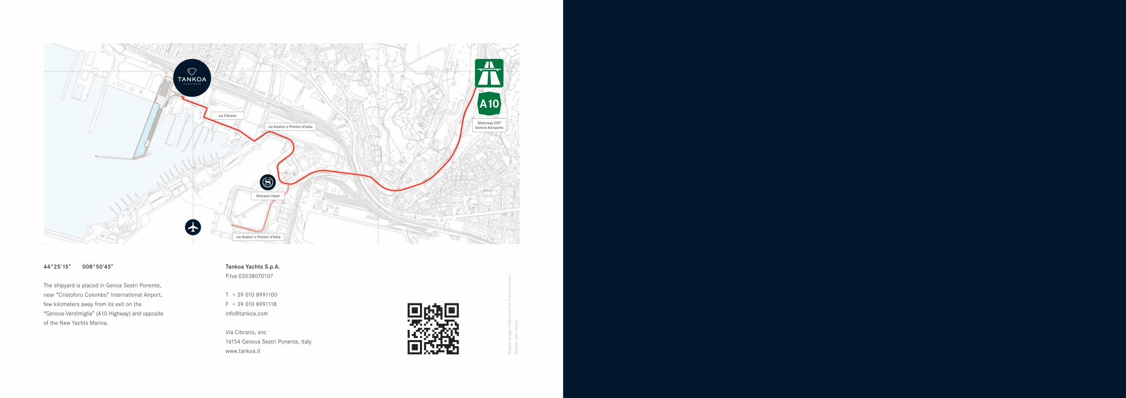
44°25’15” 008°50’45”
The shipyard is placed in Genoa Sestri Ponente,
near “Cristoforo Colombo” International Airport,
few kilometers away from its exit on the
“Genova-Ventimiglia” (A10 Highway) and opposite
of the New Yachts Marina.
Gra
phic
Des
ign:
Fed
eric
o e
Pie
r Fr
ance
sco
Pazz
i
Sta
mpa
: G
alli
Thie
rry
Tankoa Yachts S.p.A.
P.Iva 03538070107
T + 39 010 8991100
F + 39 010 8991118
Via Cibrario, snc
16154 Genova Sestri Ponente, Italy
www.tankoa.it
