parties directrices / steering parts type … page 1 section 1 information / general information...
TRANSCRIPT

MANUEL DE MAINTENANCEFIELD MAINTENANCE MANUAL
SVI - D60 - Ed 09/11
PARTIES DIRECTRICES / STEERING PARTSType PDI 60
AxleTech Internationnal France SA4, rue Jean Servanton -BP656-42042 Saint Etienne CEDEX 1FRANCETel: 33.477.92.88.00
AFTERMARKET SALESFax: 33.477.92.88.97

Page 1 D60-09/11
Section 1
Information / General information .............................page 3
Vue éclatée / Exploded view ....................................page 6
Section 2
Démontage / Disassembly ........................................page 9
Section 3
Montage / Assembly ............................................. page 13
Plans outillage / Tools drawingsExtracteur à inertie / Inertial extractor ..................................E5226Extracteur à inertie / Inertial extractor ..................................E5227
Cimblot / Drive block ..........................................E5205Cimblot / Drive block ..........................................E5207Cimblot / Drive block ..........................................E5256Cimblot / Drive block ..........................................E5257
Montage / Cover tool ............................................A5202
Sommaire / Tables of contents

Page 2
Notes

Page 3 D60-09/11
Section 1Introduction
REMARQUES CONCERNANT L'ENTRETIEN
Ce Manuel de Maintenance décrit les procédures de réparation et d'entretien correctes pour lesextrémités directrices Meritor. Les informations contenues dans ce manuel étaient d'actualité aumoment de l'impression et peuvent être modifiées sans préavis ni engagement.
Il convient que vous respectiez les procédures de sécurité de votre société lors de l'entretien ou dela réparation d'un équipement. Assurez-vous que vous avez compris toutes les procédures etinstructions avant que vous ne commenciez à travailler sur l'ensemble.
SERVICE NOTES
This field Maintenance Manual describes the correct service and repair procedures forMeritor steering parts. The information contained in this manual was current at the time ofprinting and is subject to change without notice or liability.
You must follow your company safety procedures when you service or repair equipment. Besure you understand all the procedures and instructions before you begin work on the unit.

Page 4
II ROULEMENT A ROULEAUX CONIQUES
Si la propreté des pièces au montage et la lubrification sont respectées, il est rare au démontage de trouver desroulements en mauvais état. Dans la mesure du possible on évitera donc de les démonter, car on risque avecl'extracteur de détériorer la cage ou même la cuvette si on démonte par chocs.
1) Cas de remplacement d'un roulement Usure anormale de la cuvette (visible à l'oeil nu). Piquage de la cuvette ou des galets (qui peut être dû à une mauvaise propreté, la présence d'un organe cassé dans le mécanisme ou une mauvaise lubrification).
2) Précautions au montage - On veillera à respecter les consignes suivantes : - Vérifier la propreté du roulement ; si le roulement est neuf, on ne le déballe qu'au moment de le monter ; si le roulement a déjà été monté ou déballé, on pourra le nettoyer à l'aide de white spirit, de pétrole, d'essence ou de genzol, puis l'enduire à l'huile. - Il faut, quand cela est possible, préférer un montage par refroidissement (azote liquide) ou par chauffage (huile à 80° C) à un montage par chocs. Les portées auront été auparavant soigneu sement ébavurées et nettoyées. - Si un roulement est monté par chauffage, il faut l'enduire d'huile ou de graisse après montage.
III JOINTS1) Joints toriques : après démontage, remplacer par des joints neufs.
2) Bagues d'étanchéité : nous conseillons, si de tels joints ont dû être démontés, de les remplacer. Le montage dela piste d-es joints est toujours très délicat, car on risque de blesser la lèvre d'étanchéité.On veillera donc toujours à emmancher les pièces bien en ligne, et à graisser les joints avant tout montage.Il faut de préférence graisser l'alésage devant recevoir un tel joint et s'assurer qu'il présente un très bon état desurface.Il est préférable d'emmancher les joints à la presse.
IV COUPLES DE SERRAGELes couples de serrage des éléments filetés sont indiqués dans le texte de ce manuelUn couple de serrage trop faible entraîne une sollicitation importante de l'organe fileté au cisaillement d'où unrisque de rupture.Un couple de serrage trop important entraîne une déformation excessive de l'organe filetéàl'extensionet un écrouissage des pièces en contact.
Section 1Introduction
I ENTRETIEN DES ARTICULATIONS
Pour le graissage des arbres articulés, utiliser exclusivement des graisses saponifiées au lithium répondant à laclassification de consistance 2 à pénétration 265/295 et point de goutte environ 180°C.
Périodicités :Roulement à aiguilles et tourillon : Toutes les 1000 heures ou 30 000 km.
Vérification du jeuToutes les 1000 heures ou 30 000 km.
a) Mettre un comparateur à base magnétique sur le corps de pont.
b) Utiliser un cric hydraulique pour mettre en appui le couvercle ou levierinférieur du pivot (enlever le graisseur inférieur pour éviter de l’endomma-ger)Mettre le comparateur à 0.
c) Relâcher la pression du cric et lire le jeu indiqué au comparateur.Le jeu doit-être compris entre 0 et 0,25 mm.Si le jeu mesuré est superieur à 0.25 mm, l’extrémité directrice doitêtre démontée pour remplacement des ensembles d’articulations inferieuretsupérieur (après échange des pièces d’articulation il faut refaire le ré-glage(voir procédure de réglage section 4)).En aucun cas il faut rajouter ou supprimer des cales.

Page 5 D60-09/11
Section 1Introduction
II - TAPERED ROLLER BEARINGS
If the parts are clean and properly lubricated, it is rare to find damaged bearings during removal.Therefore, one must avoid removing them because they may be damaged by the puller.
1) Case of removing of a bearingAbnormal wear of the bearing surface.Chipped bearing (due to a bad cleaning when assembled on an improper lubrication or
a broken part in the mechanism).
2) Assembly precautions Check the cleanliness of the bearing :
- It it is a new one, unpack it just before assembly, if not, it may be cleaned with petrol or benzine and thenoiled.- When it is possible one has better results by installing the bearing parts by cooling or by heating (in hotoil to 80° C) instead of using a press. A press must be prefered to a shock installer tool. The bore must becarefully deburred and cleaned before assembly of the bearing.- When a bearing has been heated for assembly, apply a small amount of grease or oil after assembly
III - SEALS
1) O'rings : after removal, renew them.
2) Lipped seals : we recommend to change them at each removal.The bore must be carefully deburred and greased before installing the seal. The fitting of the seal on the sealsurface is always difficult : care should be taken not to damage the seal Lips when fitting them.It is better to install a seal with a presse then with a shock installer tool.
IV TIGHTENING TORQUESThe tightening torques indicated in this manual must be respected : a tightening torque weaker thanindicated may lead to a shearing stress and may break the bolt.A stonger tightening torque may lead to a plastic deflection of the bolt and damage of the parts.
I - MAINTENANCE OF STEERING
For lubrication of the universal joint shafts, only Lithium base saponified greases i.a.w. the classificationwith consistency 2 penetration 265/295 and drop point of about 180°.
Lubrication intervals :Needles bearing and trunnions 1000 hours or 20 000 miles
Check steering knuckle end play. intervals 1000 hours or 20 000 miles.
a) Put a magnetic base dial indicator in positionon the housing.
b) Use a jack to put pressure on the lower knuckle cap.Set the dial indicator to zero (O ).If necessary, remove the grease fitting from the lower knuckle cap to prevent damage.
c) Fully release the jack pressure and read the end playon the dial indicator.Correct end play is between .0000" and in 0.010".If the measured end play is greater than 0.010", the steering wheel-end must be disassembled for replacement of sets of upper andlower links (after exchange of parts of links, you must readjustthe setting (see the adjustement procedure section 4)).Never add or remove shims.

Page 6
Section 1Introduction
1 Cardan complet ........................ Universal joint ..................................... 2 Roulement à aiguilles ............... Needles bearing ................................. 2a Circlips ..................................... Snapring ............................................. 2b Joint Combi SF 60x75x16 ........ Seal .................................................... 3 Roulement à aiguilles ............... Needles bearing ................................. 3a Joint Combi SF 60x75x16 ........ Seal .................................................... 4 Pivot et fusée assemblés ......... Pivot and spindle assemblies ............. 5 Vis de butée HM 16x200 .......... Screw.................................................. 6 Ecrou HM 16x200 .................... Nut ...................................................... 7 Bague PEL ............................... Bushing ............................................... 8 Joint 90x100x10/13 .................. Oil seal ................................................ 9 Cale de réglage ........................ Adjusting shim ....................................10 Tourillon ................................... Trunnion .............................................11 Couvercle ou levier .................. Cover or lever .....................................12 Vis HM 24x200x50/40-10.9 ...... Screw..................................................13 Goupilles Mécanindus .............. Cotters set ..........................................

Page 7 D60-09/11
Section 1Introduction

Page 8
Notes

Section 2Démontage / Dissassembly
Page 9 D60-09/11
Monter l'appareil sur le tambour.Déconnecter la barre d'accouplement.
Fix tool to drum.Disconnect the tie rod.
Déposer le couvercle ou le levier inférieur (11) du pivot.
Remove lever or cover (11) of the lower pivot.
Déposer le couvercle ou le levier supérieur (11) du pivot.
Remove upper lever or cover (11) from the pivot.
Pour le démontage complet du réducteur, se reporter au fascicule correspondant,répertorié dans le livret pièces de rechange planche 4.
For complete disassembly of reductor, refer to the corresponding section,listed on the spare parts booklets sheet 4

Section 2Démontage / Dissassembly
Page 10
Déposer les tourillons (9) supérieur et inférieur à l'aide del'extracteur à inertie E5226-E5227.
Remove the upper and lower trunnions (9) usingextractor E5226-E5227.
Extraire les joints (8) supérieur et inférieur du pivot à l'aided'un burin.
Extract seals (8) from upper and lower from pivotusing chisel.
Déposer l'ensemble extrémité de pont avec le cardan.
Remove the wheel end assembly together withuniversal joint.
Retirer les cales de réglage (10) des tourillons supérieuret inférieur.Reperer les cales.
Remove shims (10 ) from upper and lower trunnions.Record thickness for each position.
Attention : Si le pont possède un blocage de différentiel,celui-ci doit-être engagé.
Caution : If differential lock is used, there are mustbe engaged.
!

Section 2Démontage / Dissassembly
Page 11 D60-09/11
Si le réducteur a été démontéIn the case of reductor removal:
Déposer le joint (3a) du pivot.
Remove seal (3a) from pivot.
Déposer le pivot (4),
Remove the pivot (4),
Retirer le cardan (1).Attention : Si le pont possède un blocage de différen-tiel, celui-ci doit-être engagé.
Remove universal joint (1).Caution : If differential lock is used, there are mustbe engaged.
Déposer le roulement (3) du pivot.
Remove needle bearing (3) from pivot.

Section 2Démontage / Dissassembly
Page 12
Déposer le joint (2a), le circlips (2), extraire le roulement(2) du corps de pont à l'aide d'un extracteur à inertie.
Remove seal (2a), snap ring (2), and extract bearing(2) from axle housing using inertial extractor.
Enlever la bague supérieure (7) du bol d'articulation àl'aide d'un burin (si besoin chauffer).
Remove upper bushing (7) from socket using chisel(if needed, heat around it).

Section 3Montage / Assembly
Page 13 D60-09/11
Emmancher le roulement (2) légèrement huilé dans lecorps de pont à l'aide du cimblot E5207.
Insert lightly-greased bearing (2) in axle housingusing drift block E5207.
Emmancher la bague supérieure (7) à l'aide du cimblotE5205.
Use block E5205 to fit the upper bushing (7).
Monter le circlips intérieur (2) dans le corps du pont.
Fit the internal snap ring (2) into the axle housing.
ATTENTION :Il est impératif de remonter des joints neufs.
Toutes les graisses chargées en lubrifiants solides sont INTERDITES (par exemple : graisse de bisulfure).Graisses conseillées : DARINA 2 (SHELL)
MULTIS EP 2 (TOTAL)
CAUTION:New seals must be used.
DO NOT USE grease in form of solidified lubricants (for example: bisulphide grease)Recommended greases: DARINA 2 (SHELL)
MULTI EP 2 (TOTAL)

Section 3Montage / Assembly
Page 14
Emmancher le joint (2a) dans le corps de pont, à l'aidedu cimblot E5207.Graisser les lèvres inférieures du joint.
Fit the seal (2a) into the axle housing using driftblock E5207.Grease the lower edges of seal.
Graisser l'intérieur des bagues (7) supérieur et inférieur.
Grease inside of upper and lower bushing (7).
Mettre en place l'extrémité de roue et le cardan, alignerles cannelures de l'arbre avec le différentiel.Attention: Si le pont possède un blocage de différentiel, celui-cidoit-être dans un premier temps, impérativement enclenchépour engager l'arbre du cardan, puis relacher pour finir l'engage-ment.
Position the wheel end and universal joint together ;align splines of shaft with those of differential.Caution : If differential lock is used, this one must beengaged to fit the shaft and desengaged to engagethe shaft into the side gear.
Graisser les joints (8) et les mettre en place sur lestourillons (9).
Grease seals (8) and fit them on the trunnions (9).
Si le réducteur a été démonté, voir page 18.In the case of reductor removal, see page 18
Section 3Montage / Assembly
Page 15 D60-09/11
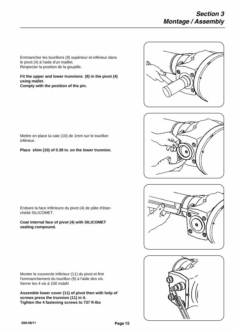
Enduire la face inférieure du pivot (4) de pâte d'étan-chéité SILICOMET.
Coat internal face of pivot (4) with SILICOMETsealing compound.
Emmancher les tourillons (9) supérieur et inférieur dansle pivot (4) à l'aide d'un maillet.Respecter la position de la goupille.
Fit the upper and lower trunnions (9) in the pivot (4)using mallet.Comply with the position of the pin.
Mettre en place la cale (10) de 1mm sur le tourilloninférieur.
Place shim (10) of 0.39 in. on the lower trunnion.
Monter le couvercle inférieur (11) du pivot et finirl'emmanchement du tourillon (9) à l'aide des vis.Serrer les 4 vis à 100 mdaN
Assemble lower cover (11) of pivot then with help ofscrews press the trunnion (11) in it.Tighten the 4 fastening screws to 737 ft-lbs

Section 3Montage / Assembly
Page 16
Retirer l'outillage, enduire la face du pivot (4) de pâted'étancheité SILICOMET.
Remove special tool, coat face of knuckle (4) withSILICOMET sealing compound.
Sur la face supérieur du pivot, mettre en place l'outillageA5202, le fixer avec 2 vis en opposition, serrées à 30 mdaN.Serrer la vis centrale de 25 à 30 mdaN.Faire manœuvrer le pivot plusieurs fois et resserrer la vis,répéter l'opération jusqu'à rattraper les jeux.S'assurer que l'ensemble pivote sans jeux et sans dureté.
On upper pivot, install tool A5202, fasten it with 2 screwsassembled opposite each other, tightened to 220 ft/lbs.Tighten central screw to 185-220 ft/lbs.Move pivot around a few times, slacken central screwand retighten until there is no play.Chek that assembly is neither overlight nor overloose.
Mesurer à l'aide d'une jauge de profondeur le calage àeffectuer.
Use depth gauge to measure shims needed.
Détermination de la cale (10) - C = A - B
Shim (10) thickness needed - C = A - B
Section 3Montage / Assembly
Page 17 D60-09/11
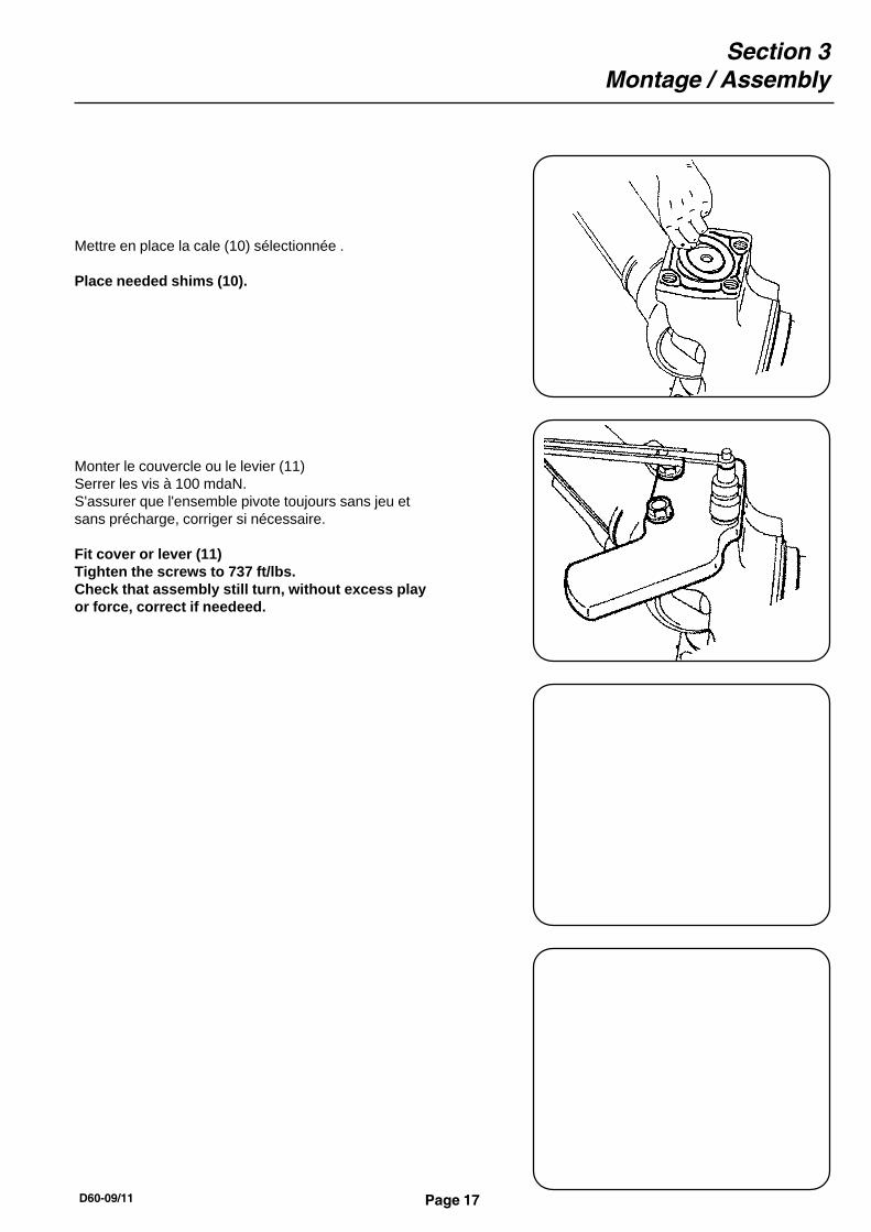
Mettre en place la cale (10) sélectionnée .
Place needed shims (10).
Monter le couvercle ou le levier (11)Serrer les vis à 100 mdaN.S'assurer que l'ensemble pivote toujours sans jeu etsans précharge, corriger si nécessaire.
Fit cover or lever (11)Tighten the screws to 737 ft/lbs.Check that assembly still turn, without excess playor force, correct if needeed.

Section 3Montage / Assembly
Page 18
Si le réducteur a été démonté / In the case of reductor removal:
Mettre en place le cardan (1) (aligner les cannelures du cardanavec celles du différentiel).S'assurer que le cardan coulisse librement.Attention: Si le pont possède un blocage de différentiel, celui-cidoit-être dans un premier temps, impérativement enclenchépour engager l'arbre du cardan, puis relacher pour finir l'engage-ment.
Fit double cardan joint (1) (align splines of universal jointwith those of differential).Check that universal joint shaft slides free.Caution : If differential lock is used, this one must beengaged to fit the shaft and desengaged to engage theshaft into the side gear.
Emmancher le roulement (3) légèrement huilé dans le pivotà l'aide du cimblot E5256.
Insert lightly-greased bearing (3) on knuckle using adrift block E5256.
Emmancher le joint (3a) dans le pivot à l'aide du cimblot E5257.Graisser les lèvres inférieures du joint.
Fit the seal (3a) in the knuckle using drift block E5257.Grease the lower edges of seal.
Mettre en place le pivot (4) sur le corps du pont.
Place pivot (4) on axle housing.