particle trapping and conveying using an optical archimedes’...
TRANSCRIPT
Particle trapping and conveying using anoptical Archimedes’ screwBARAK HADAD,1,2,† SAHAR FROIM,1,2,† HAREL NAGAR,2,3 TAMIR ADMON,2,3 YANIV ELIEZER,1,2 YAEL ROICHMAN,2,3
AND ALON BAHABAD1,2,*1Department of Physical Electronics, School of Electrical Engineering, Fleischman Faculty of Engineering, Tel-Aviv University, Tel-Aviv 69978, Israel2Tel-Aviv University Center for Light-Matter-Interaction, Tel Aviv 6997801, Israel3School of Chemistry, Raymond and Beverly Sackler Faculty of Exact Sciences, Tel Aviv University, Tel Aviv 69978, Israel*Corresponding author: [email protected]
Received 18 December 2017; revised 11 March 2018; accepted 27 March 2018 (Doc. ID 314918); published 2 May 2018
Trapping and manipulation of particles using laser beams has become an important tool in diverse fields of research.In recent years, particular interest has been devoted to the problem of conveying optically trapped particles overextended distances either downstream or upstream of the direction of photon momentum flow. Here, we proposeand experimentally demonstrate an optical analog of the famous Archimedes’ screw where the rotation of a helical-intensity beam is transferred to the axial motion of optically trapped micrometer-scale, airborne, carbon-basedparticles. With this optical screw, particles were easily conveyed with controlled velocity and direction, upstreamor downstream of the optical flow, over a distance of half a centimeter. Our results offer a very simple optical conveyorthat could be adapted to a wide range of optical trapping scenarios. ©2018Optical Society of America under the terms of the
OSA Open Access Publishing Agreement
OCIS codes: (350.4855) Optical tweezers or optical manipulation; (140.7010) Laser trapping; (140.3300) Laser beam shaping.
https://doi.org/10.1364/OPTICA.5.000551
1. INTRODUCTION
Optical trapping and translation of particles using focused laserbeams has become an important and useful tool in various dis-ciplines such as biology, atomic physics, optics, thermodynamics,and atmospheric sciences [1–6]. For weakly absorbing, sub-wavelength particles, optical trapping and manipulation is basedon the interplay of two forces that act on the trapped particles,both of which are caused by radiation pressure [1]. The first forcedepends on the gradient of the light’s intensity, which attracts theparticle toward the focal point of the beam. The second force isthe scattering force, which usually pushes the particle downstreamalong the beam’s direction of propagation (in special arrange-ments, the scattering force can be set to pull particles againstthe momentum flow [7]). These two forces need to counteracteach other in order to obtain a stable optical trap. With absorbingparticles, the photophoretic force becomes dominant. The photo-phoretic force is proportional to particle size and the light’s inten-sity. This force is thermal in nature, namely, when light hits oneside of a particle, that side becomes warmer, increasing the pres-sure of the nearby air molecules. The resulting pressure dropbetween the warm and cold sides of the particle pushes themdownstream, and away from the light. This force tends to repelan absorbing particle from high-intensity regions of an opticalbeam. It has been shown that the ratio of photophoretic forcesand radiation pressure forces for absorbing sub-wavelength particles
is close to 104 [8]. Therefore, for such particles, radiation pres-sure forces can be neglected, whereas photophoretic force governsparticle transportation up to a meter length scale [9]. Specialinterest is devoted to developing optical tractor beams, whichallow the transfer of particles against the direction of the beam’spropagation, i.e., the direction of the beam’s momentum. Thisposes an interesting challenge since it requires moving a particleagainst the direction of both photophoretic forces and radiationpressure forces when a simple Gaussian beam is used. In additionto moving particles upstream, such tractor beams, also knownas optical conveyors, are generally required to transport particlesin both directions, upstream and downstream, in a controlledmanner. For weakly absorbing particles, in a solution, optical con-veyors were realized using a superposition of two Bessel beams,while changing the relative phase between them [10]. This changein phase shifts the standing-wave pattern of the structured beam,carrying along particles trapped at the standing-wave intensitycrests. For airborne absorbing particles that are expelled fromhigh-intensity regions, the common practice is to use hollowedbeams with dark volumes to trap the particles and then move thedark volume [11,12]. Alternatively, particles were manipulatedby changing the polarization of the beam [13]. For asymmetricairborne particles, it was shown experimentally that the axiallocation of a trapped particle can be controlled by changingthe intensity of a single Gaussian beam [14]. Many of the beams
2334-2536/18/050551-06 Journal © 2018 Optical Society of America
Research Article Vol. 5, No. 5 / May 2018 / Optica 551
used in optical trapping use spatial modes with orbital angularmomenta (OAMs) [15–18]. These modes enable both thegeneration of hollowed beams useful in trapping absorbing air-borne particles [9,13,19,20] and the transportation of particlesalong helical trajectories [21,22].
Here we present, experimentally, the use of a helical beam,made from the superposition of modes with different OAMsand different axial wave vector components, to trap and transportabsorbing airborne particles up- and downstream by rotating thebeam one way or the other. This technique is an optical realizationof the famous Archimedes’ screw, used to draw water from under-ground wells. Not too close to the focus of the beam, the particlemotion is matched to the movement of the optical screw, enablingrobust and scalable two-way conveying. We would like to notethat in recent years, an optical Archimedes screw was suggestedfor manipulating the movement of trapped cold atoms [23,24].
2. RESULTS
A. Experimental Setup
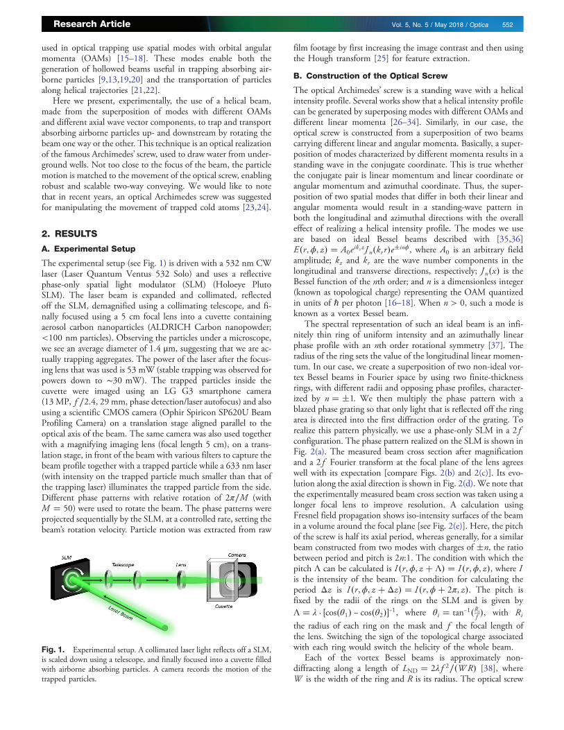
The experimental setup (see Fig. 1) is driven with a 532 nm CWlaser (Laser Quantum Ventus 532 Solo) and uses a reflectivephase-only spatial light modulator (SLM) (Holoeye PlutoSLM). The laser beam is expanded and collimated, reflectedoff the SLM, demagnified using a collimating telescope, and fi-nally focused using a 5 cm focal lens into a cuvette containingaerosol carbon nanoparticles (ALDRICH Carbon nanopowder;<100 nm particles). Observing the particles under a microscope,we see an average diameter of 1.4 μm, suggesting that we are ac-tually trapping aggregates. The power of the laser after the focus-ing lens that was used is 53 mW (stable trapping was observed forpowers down to ∼30 mW). The trapped particles inside thecuvette were imaged using an LG G3 smartphone camera(13 MP, f ∕2.4, 29 mm, phase detection/laser autofocus) and alsousing a scientific CMOS camera (Ophir Spiricon SP620U BeamProfiling Camera) on a translation stage aligned parallel to theoptical axis of the beam. The same camera was also used togetherwith a magnifying imaging lens (focal length 5 cm), on a trans-lation stage, in front of the beam with various filters to capture thebeam profile together with a trapped particle while a 633 nm laser(with intensity on the trapped particle much smaller than that ofthe trapping laser) illuminates the trapped particle from the side.Different phase patterns with relative rotation of 2π∕M (withM � 50) were used to rotate the beam. The phase patterns wereprojected sequentially by the SLM, at a controlled rate, setting thebeam’s rotation velocity. Particle motion was extracted from raw
film footage by first increasing the image contrast and then usingthe Hough transform [25] for feature extraction.
B. Construction of the Optical Screw
The optical Archimedes’ screw is a standing wave with a helicalintensity profile. Several works show that a helical intensity profilecan be generated by superposing modes with different OAMs anddifferent linear momenta [26–34]. Similarly, in our case, theoptical screw is constructed from a superposition of two beamscarrying different linear and angular momenta. Basically, a super-position of modes characterized by different momenta results in astanding wave in the conjugate coordinate. This is true whetherthe conjugate pair is linear momentum and linear coordinate orangular momentum and azimuthal coordinate. Thus, the super-position of two spatial modes that differ in both their linear andangular momenta would result in a standing-wave pattern inboth the longitudinal and azimuthal directions with the overalleffect of realizing a helical intensity profile. The modes we useare based on ideal Bessel beams described with [35,36]E�r,ϕ, z� � A0eikz zJn�krr�e�inϕ, where A0 is an arbitrary fieldamplitude; kz and kr are the wave number components in thelongitudinal and transverse directions, respectively; Jn�x� is theBessel function of the nth order; and n is a dimensionless integer(known as topological charge) representing the OAM quantizedin units of ℏ per photon [16–18]. When n > 0, such a mode isknown as a vortex Bessel beam.
The spectral representation of such an ideal beam is an infi-nitely thin ring of uniform intensity and an azimuthally linearphase profile with an nth order rotational symmetry [37]. Theradius of the ring sets the value of the longitudinal linear momen-tum. In our case, we create a superposition of two non-ideal vor-tex Bessel beams in Fourier space by using two finite-thicknessrings, with different radii and opposing phase profiles, character-ized by n � �1. We then multiply the phase pattern with ablazed phase grating so that only light that is reflected off the ringarea is directed into the first diffraction order of the grating. Torealize this pattern physically, we use a phase-only SLM in a 2fconfiguration. The phase pattern realized on the SLM is shown inFig. 2(a). The measured beam cross section after magnificationand a 2f Fourier transform at the focal plane of the lens agreeswell with its expectation [compare Figs. 2(b) and 2(c)]. Its evo-lution along the axial direction is shown in Fig. 2(d). We note thatthe experimentally measured beam cross section was taken using alonger focal lens to improve resolution. A calculation usingFresnel field propagation shows iso-intensity surfaces of the beamin a volume around the focal plane [see Fig. 2(e)]. Here, the pitchof the screw is half its axial period, whereas generally, for a similarbeam constructed from two modes with charges of �n, the ratiobetween period and pitch is 2n:1. The condition with which thepitch Λ can be calculated is I�r,ϕ, z � Λ� � I�r,ϕ, z�, where Iis the intensity of the beam. The condition for calculating theperiod Δz is I�r,ϕ, z � Δz� � I�r,ϕ� 2π, z�. The pitch isfixed by the radii of the rings on the SLM and is given byΛ � λ · �cos�θ1� − cos�θ2��−1, where θi � tan−1�Ri
f �, with Ri
the radius of each ring on the mask and f the focal length ofthe lens. Switching the sign of the topological charge associatedwith each ring would switch the helicity of the whole beam.
Each of the vortex Bessel beams is approximately non-diffracting along a length of LND � 2λf 2∕�WR� [38], whereW is the width of the ring and R is its radius. The optical screw
Fig. 1. Experimental setup. A collimated laser light reflects off a SLM,is scaled down using a telescope, and finally focused into a cuvette filledwith airborne absorbing particles. A camera records the motion of thetrapped particles.
Research Article Vol. 5, No. 5 / May 2018 / Optica 552

retains its form along this length, but starts to broaden furtherupstream or downstream due to diffraction. The central partof the beam is composed of 2n intertwining strands. A rotationof the optical screw around the propagation axis is easily accom-plished by rotating either one or both of the rings on the SLM.In the first case, the interference pattern is rotating, whereas inthe second, it is the whole beam. The overall effect is similar, withthe difference (for the case n = 1) that a Δθ rotation of one of therings is the same as rotating the whole beam by Δθ∕2. When aparticle is trapped at one of the off-axis dark volumes in the beam,it is carried upstream or downstream depending on the directionof beam rotation and beam helicity (which is constant in ourexperiment).
C. Screw-Velocity-Matched Particle Motion
A particle trapped in the optical screw maintains its position aslong as the screw is stationary. The trapping stiffness is estimatedto be around 50 pN/m (see Supplement 1). When the screw isrotating, the trapped particle is translated in a controlled manner,as long as it remains far enough from the focal plane of the beam(1 mm away in our case), and is driven at velocities lower than
∼0.3 mm∕s. The axial movement of the particle in these cases isclose to the axial phase velocity of the optical screw, defined as thescrew period divided by the screw’s rotation time period. The par-ticle is repelled from the high-intensity regions of the rotatingbeam, very similarly to water or air molecules being repelled fromthe blades of a rotating fan. The small diffraction of the screw isresponsible for the difference between the actual axial velocity ofthe particle and the calculated phase velocity (which is exact onlyfor an infinitely non-diffracting beam). Still we describe this typeof movement as screw-velocity-matched movement.
As a demonstration, we accomplish periodic oscillatory motionof trapped particles by repeatedly rotating the screw one way, andthen the other. This oscillatory motion is repeated with two differ-ent rotation speeds and with different number of rotations of thescrew to each side. The axial (z direction) movement of thetrapped particles for these cases are shown in Fig. 3. The twophase velocities we used are 0.08 mm/s [Figs. 3(a) and 3(c)] and0.04 mm/s [Figs. 3(b) and 3(d)]. The number of screw rotationswe used to each side was half a turn [N � 0.5; Figs. 3(a) and3(b)] and three quarters of a turn [N � 0.75; Figs. 3(c) and 3(d)].In total, we then have four different movements of the screw and
Fig. 2. Optical Archimedes’ screw. (a) The Fourier domain mask that was applied to the phase-only SLM. (b) Calculation of beam profile in the focalplane at the middle of the cuvette. The arrows indicate dark volumes in which particles were observed to be trapped. (c) Beam profile captured on acamera, using a lens of a longer focal length than used for trapping, and scale-adjusted for the lens used for trapping. (d) Calculation of beam profile atseveral locations along the propagation length. (e) Simulation of several iso-intensity surfaces of the beam around the focal plane. (f ) Simulations, forseveral rotation angles ϕ of the optical screw, of a plane cut [as shown in (e)] of the beam parallel to the optical axis and displaced transversely to the pointindicated by one of the arrows on panel (b) above. The dashed white circles denote a possible trap location for the particle. The white arrows are a guide tothe eye.
Research Article Vol. 5, No. 5 / May 2018 / Optica 553
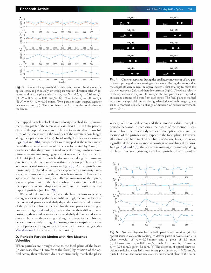
the trapped particle is locked and velocity-matched to this move-ment. The pitch of the screw in all cases was 4.1 mm (The param-eters of the optical screw were chosen to create about two fullturns of the screw within the confines of the cuvette whose lengthalong the optical axis is 2 cm). Incidentally, for the cases shown inFigs. 3(a) and 3(b), two particles were trapped at the same time attwo different axial locations of the screw (separated by 2 mm). Itcan be seen that they move in tandem performing similar motion.Using a magnifying imaging system, it was verified (with an errorof�0.44 μm ) that the particles do not move along the transversedirections, while their location within the beam profile is set off-axis as indicated using an arrow in Fig. 2(b). As the particles aretransversely displaced off-axis, they experience an intensity land-scape that moves axially as the screw is being rotated. This can beappreciated by examining, for different rotations of the opticalscrew, a plane cut of the beam whose location is parallel tothe optical axis and displaced off-axis to the position of thetrapped particles [see Fig. 2(f )].
We would like to note that, since the beam retains some slowdivergence (it is not perfectly non-diffracting), the axial velocity ofthe conveyed particles is slightly dependent on the axial positionof the particles. This can be seen for the two particles moving intandem in Figs. 3(a) and 3(b), where due to their different axialpositions, their axial velocities are also slightly different and so thedistance between them changes along their trajectories. This canbe seen more clearly in Fig. 4 showing camera snapshots for thepair of particles during an oscillation of their movement (see alsoVisualization 1 for a video of this motion).
D. Periodic Particle Motion with Non-MatchedVelocities
When particles are brought close to the focal plane of the beam(in our case, about 1 mm from the focus) by rotation of the op-tical screw, their velocities do not continuously match the phase
velocity of the optical screw, and their motions exhibit complexperiodic behavior. In such cases, the nature of the motion is sen-sitive to both the rotation dynamics of the optical screw and thelocation of the particles with respect to the focal plane. However,all motions we have tracked exhibit periodic oscillatory behavior,regardless if the screw rotation is constant or switching directions.In Figs. 5(a) and 5(b), the screw was rotating continuously alongthe beam direction (striving to deliver particles downstream) at
0 50 100 150 200 250 300 350 400 450-15
-10
-5
0z
[mm
]
0 50 100 150 200 250 300 350 400 450-15
-10
-5
0
z [m
m]
0 50 100 150 200 250 300 350 400 450-15
-10
-5
0
z [m
m]
0 50 100 150 200 250 300 350 400 450time [s]
-15
-10
-5
0
z [m
m]
(a)
(b)
(c)
(d)
Fig. 3. Screw-velocity-matched particle axial motion. In all cases, theoptical screw is periodically switching its rotation direction after N ro-tations and its axial phase velocity is vp. (a) N � 0.5, vp � 0.08 mm∕s.(b) N � 0.5, vp � 0.04 mm∕s. (c) N � 0.75, vp � 0.08 mm∕s.(d) N � 0.75, vp � 0.04 mm∕s. Two particles were trapped togetherin cases (a) and (b). The coordinate z = 0 marks the focal plane ofthe beam.
2mm
2mm
2mm
2mm
2mm
2mm
2mm
2mm
2mm
2mm
t=t0+0 t
t=t0+1 t
t=t0+2 t
t=t0+3 t
t=t0+4 t
t=t0+5 t
t=t0+6 t
t=t0+7 t
t=t0+8 t
t=t0+9 t
Fig. 4. Camera snapshots during the oscillatory movement of two par-ticles trapped together in a rotating optical screw. During the interval thatthe snapshots were taken, the optical screw is first rotating to move theparticles upstream (left) and then downstream (right). The phase velocityof the optical screw is vp � 0.08 mm∕s. The two particles are trapped atan average distance of 2 mm from each other. The focal plane is markedwith a vertical (purple) line on the right-hand side of each image. t0 wasset to a moment just after a change of direction of particle movement.Δt � 10 s.
0 50 100 150 200 250-2
0
2
z [m
m]
0 50 100 150 200 250-2
0
2
z [m
m]
0 50 100 150 200 2500
5
10
z [m
m]
0 50 100 150 200 250time [s]
-4
-2
0
z [m
m]
(a)
(b)
(c)
(d)
Fig. 5. Non velocity-matched periodic particle axial motion. (a) Theoptical screw is constantly rotating to deliver particles downstream at aphase velocity of vp � 0.08 mm∕s and a pitch of 4.1 mm.(b) Downstream, vp � 0.03 mm∕s, pitch 4.1 mm. (c) Upstream,vp � 0.08 mm∕s, pitch 4.1 mm. (d) The direction of optical screw ro-tation is switched every half a turn (every pitch cycle); vp � 0.23 mm∕s,pitch 11.3 mm. The coordinate z = 0 marks the focal plane of the beam.
Research Article Vol. 5, No. 5 / May 2018 / Optica 554
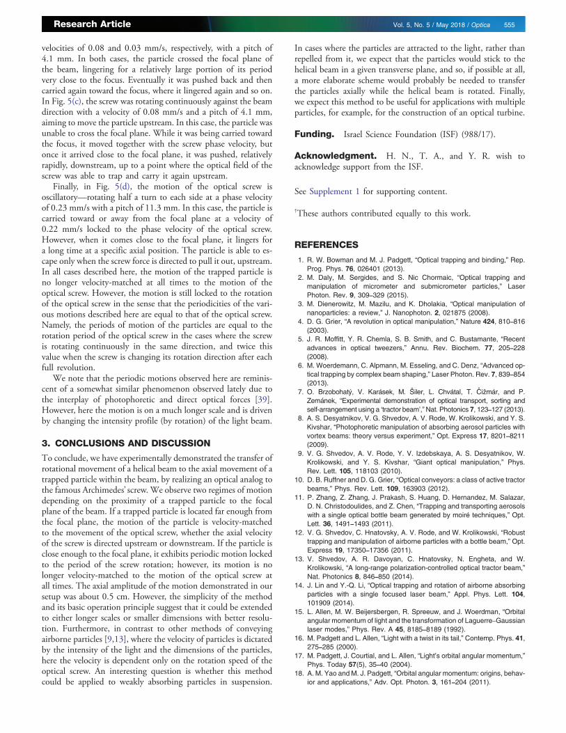
velocities of 0.08 and 0.03 mm/s, respectively, with a pitch of4.1 mm. In both cases, the particle crossed the focal plane ofthe beam, lingering for a relatively large portion of its periodvery close to the focus. Eventually it was pushed back and thencarried again toward the focus, where it lingered again and so on.In Fig. 5(c), the screw was rotating continuously against the beamdirection with a velocity of 0.08 mm/s and a pitch of 4.1 mm,aiming to move the particle upstream. In this case, the particle wasunable to cross the focal plane. While it was being carried towardthe focus, it moved together with the screw phase velocity, butonce it arrived close to the focal plane, it was pushed, relativelyrapidly, downstream, up to a point where the optical field of thescrew was able to trap and carry it again upstream.
Finally, in Fig. 5(d), the motion of the optical screw isoscillatory—rotating half a turn to each side at a phase velocityof 0.23 mm/s with a pitch of 11.3 mm. In this case, the particle iscarried toward or away from the focal plane at a velocity of0.22 mm/s locked to the phase velocity of the optical screw.However, when it comes close to the focal plane, it lingers fora long time at a specific axial position. The particle is able to es-cape only when the screw force is directed to pull it out, upstream.In all cases described here, the motion of the trapped particle isno longer velocity-matched at all times to the motion of theoptical screw. However, the motion is still locked to the rotationof the optical screw in the sense that the periodicities of the vari-ous motions described here are equal to that of the optical screw.Namely, the periods of motion of the particles are equal to therotation period of the optical screw in the cases where the screwis rotating continuously in the same direction, and twice thisvalue when the screw is changing its rotation direction after eachfull revolution.
We note that the periodic motions observed here are reminis-cent of a somewhat similar phenomenon observed lately due tothe interplay of photophoretic and direct optical forces [39].However, here the motion is on a much longer scale and is drivenby changing the intensity profile (by rotation) of the light beam.
3. CONCLUSIONS AND DISCUSSION
To conclude, we have experimentally demonstrated the transfer ofrotational movement of a helical beam to the axial movement of atrapped particle within the beam, by realizing an optical analog tothe famous Archimedes’ screw. We observe two regimes of motiondepending on the proximity of a trapped particle to the focalplane of the beam. If a trapped particle is located far enough fromthe focal plane, the motion of the particle is velocity-matchedto the movement of the optical screw, whether the axial velocityof the screw is directed upstream or downstream. If the particle isclose enough to the focal plane, it exhibits periodic motion lockedto the period of the screw rotation; however, its motion is nolonger velocity-matched to the motion of the optical screw atall times. The axial amplitude of the motion demonstrated in oursetup was about 0.5 cm. However, the simplicity of the methodand its basic operation principle suggest that it could be extendedto either longer scales or smaller dimensions with better resolu-tion. Furthermore, in contrast to other methods of conveyingairborne particles [9,13], where the velocity of particles is dictatedby the intensity of the light and the dimensions of the particles,here the velocity is dependent only on the rotation speed of theoptical screw. An interesting question is whether this methodcould be applied to weakly absorbing particles in suspension.
In cases where the particles are attracted to the light, rather thanrepelled from it, we expect that the particles would stick to thehelical beam in a given transverse plane, and so, if possible at all,a more elaborate scheme would probably be needed to transferthe particles axially while the helical beam is rotated. Finally,we expect this method to be useful for applications with multipleparticles, for example, for the construction of an optical turbine.
Funding. Israel Science Foundation (ISF) (988/17).
Acknowledgment. H. N., T. A., and Y. R. wish toacknowledge support from the ISF.
See Supplement 1 for supporting content.
†These authors contributed equally to this work.
REFERENCES
1. R. W. Bowman and M. J. Padgett, “Optical trapping and binding,” Rep.Prog. Phys. 76, 026401 (2013).
2. M. Daly, M. Sergides, and S. Nic Chormaic, “Optical trapping andmanipulation of micrometer and submicrometer particles,” LaserPhoton. Rev. 9, 309–329 (2015).
3. M. Dienerowitz, M. Mazilu, and K. Dholakia, “Optical manipulation ofnanoparticles: a review,” J. Nanophoton. 2, 021875 (2008).
4. D. G. Grier, “A revolution in optical manipulation,” Nature 424, 810–816(2003).
5. J. R. Moffitt, Y. R. Chemla, S. B. Smith, and C. Bustamante, “Recentadvances in optical tweezers,” Annu. Rev. Biochem. 77, 205–228(2008).
6. M. Woerdemann, C. Alpmann, M. Esseling, and C. Denz, “Advanced op-tical trapping by complex beam shaping,” Laser Photon. Rev. 7, 839–854(2013).
7. O. Brzobohatý, V. Karásek, M. Šiler, L. Chvátal, T. Cižmár, and P.Zemánek, “Experimental demonstration of optical transport, sorting andself-arrangement using a ‘tractor beam’,”Nat. Photonics 7, 123–127 (2013).
8. A. S. Desyatnikov, V. G. Shvedov, A. V. Rode, W. Krolikowski, and Y. S.Kivshar, “Photophoretic manipulation of absorbing aerosol particles withvortex beams: theory versus experiment,” Opt. Express 17, 8201–8211(2009).
9. V. G. Shvedov, A. V. Rode, Y. V. Izdebskaya, A. S. Desyatnikov, W.Krolikowski, and Y. S. Kivshar, “Giant optical manipulation,” Phys.Rev. Lett. 105, 118103 (2010).
10. D. B. Ruffner and D. G. Grier, “Optical conveyors: a class of active tractorbeams,” Phys. Rev. Lett. 109, 163903 (2012).
11. P. Zhang, Z. Zhang, J. Prakash, S. Huang, D. Hernandez, M. Salazar,D. N. Christodoulides, and Z. Chen, “Trapping and transporting aerosolswith a single optical bottle beam generated by moiré techniques,” Opt.Lett. 36, 1491–1493 (2011).
12. V. G. Shvedov, C. Hnatovsky, A. V. Rode, and W. Krolikowski, “Robusttrapping and manipulation of airborne particles with a bottle beam,” Opt.Express 19, 17350–17356 (2011).
13. V. Shvedov, A. R. Davoyan, C. Hnatovsky, N. Engheta, and W.Krolikowski, “A long-range polarization-controlled optical tractor beam,”Nat. Photonics 8, 846–850 (2014).
14. J. Lin and Y.-Q. Li, “Optical trapping and rotation of airborne absorbingparticles with a single focused laser beam,” Appl. Phys. Lett. 104,101909 (2014).
15. L. Allen, M. W. Beijersbergen, R. Spreeuw, and J. Woerdman, “Orbitalangular momentum of light and the transformation of Laguerre–Gaussianlaser modes,” Phys. Rev. A 45, 8185–8189 (1992).
16. M. Padgett and L. Allen, “Light with a twist in its tail,” Contemp. Phys. 41,275–285 (2000).
17. M. Padgett, J. Courtial, and L. Allen, “Light’s orbital angular momentum,”Phys. Today 57(5), 35–40 (2004).
18. A. M. Yao and M. J. Padgett, “Orbital angular momentum: origins, behav-ior and applications,” Adv. Opt. Photon. 3, 161–204 (2011).
Research Article Vol. 5, No. 5 / May 2018 / Optica 555
19. V. Shvedov, A. S. Desyatnikov, A. V. Rode, Y. Izdebskaya, W.Krolikowski, and Y. S. Kivshar, “Optical vortex beams for trapping andtransport of particles in air,” Appl. Phys. A 100, 327–331 (2010).
20. V. G. Shvedov, A. S. Desyatnikov, A. V. Rode, W. Krolikowski, and Y. S.Kivshar, “Optical guiding of absorbing nanoclusters in air,” Opt. Express17, 5743–5757 (2009).
21. S.-H. Lee, Y. Roichman, and D. G. Grier, “Optical solenoid beams,” Opt.Express 18, 6988–6993 (2010).
22. J. Zhao, I. D. Chremmos, D. Song, D. N. Christodoulides, N. K.Efremidis, and Z. Chen, “Curved singular beams for three-dimensionalparticle manipulation,” Sci. Rep. 5, 12086 (2015).
23. A. Y. Okulov, “Cold matter trapping via slowly rotating helical potential,”Phys. Lett. A 376, 650–655 (2012).
24. A. Al Rsheed, A. Lyras, O. M. Aldossary, and V. E. Lembessis, “Rotatingoptical tubes for vertical transport of atoms,” Phys. Rev. A 94, 063423(2016).
25. J. Illingworth and J. Kittler, “A survey of the Hough transform,” Comput.Vis. Graph. Image Process. 44, 87–116 (1988).
26. C. Schulze, F. S. Roux, A. Dudley, R. Rop, M. Duparré, and A. Forbes,“Accelerated rotation with orbital angular momentummodes,” Phys. Rev.A 91, 043821 (2015).
27. C. Vetter, T. Eichelkraut, M. Ornigotti, and A. Szameit, “Generalized ra-dially self-accelerating helicon beams,” Phys. Rev. Lett. 113, 183901(2014).
28. V. Kotlyar, S. Khonina, R. Skidanov, and V. Soifer, “Rotation of laserbeams with zero of the orbital angular momentum,” Opt. Commun.274, 8–14 (2007).
29. R. Rop, A. Dudley, C. López-Mariscal, and A. Forbes, “Measuring therotation rates of superpositions of higher-order Bessel beams,”J. Mod. Opt. 59, 259–267 (2012).
30. Y. Y. Schechner, R. Piestun, and J. Shamir, “Wave propagation withrotating intensity distributions,” Phys. Rev. E 54, R50–R53 (1996).
31. S. Tao, X.-C. Yuan, J. Lin, and R. Burge, “Residue orbital angular mo-mentum in interferenced double vortex beams with unequal topologicalcharges,” Opt. Express 14, 535–541 (2006).
32. R. Vasilyeu, A. Dudley, N. Khilo, and A. Forbes, “Generating superpositionsof higher-order Bessel beams,” Opt. Express 17, 23389–23395 (2009).
33. S. Zheng, Y. Cai, Y. Li, J. Li, G. Zheng, H. Chen, and S. Xu, “Rotatingwave packet caused by the superposition of two Bessel–Gauss beams,”J. Opt. 17, 125602 (2015).
34. A. Dudley and A. Forbes, “From stationary annular rings to rotatingBessel beams,” J. Opt. Soc. Am. A 29, 567–573 (2012).
35. J. Durnin, “Exact solutions for nondiffracting beams. i. The scalar theory,”J. Opt. Soc. Am. A 4, 651–654 (1987).
36. D. McGloin and K. Dholakia, “Bessel beams: diffraction in a new light,”Contemp. Phys. 46, 15–28 (2005).
37. J. Durnin, J. Miceli, Jr., and J. Eberly, “Diffraction-free beams,” Phys.Rev. Lett. 58, 1499–1501 (1987).
38. L. Lobachinsky, L. Hareli, Y. Eliezer, L. Michaeli, and A. Bahabad, “Onthe fly control of high harmonic generation using a structured pumpbeam,” Phys. Rev. Lett., to be published.
39. J. Lu, H. Yang, L. Zhou, Y. Yang, S. Luo, Q. Li, and M. Qiu, “Light-induced pulling and pushing by the synergic effect of optical forceand photophoretic force,” Phys. Rev. Lett. 118, 043601 (2017).
Research Article Vol. 5, No. 5 / May 2018 / Optica 556